 Open Access Article
Strategies for the design of ruthenium-based electrocatalysts toward acidic oxygen evolution reaction
Liqiang
Hou
a,
Xiumin
Gu
a,
Xuemei
Cui
a,
Jiachen
Tang
a,
Zijian
Li
b,
Xien
Liu
 *a and
Jaephil
Cho
 *c
*c
aState Key Laboratory Base of Eco-Chemical Engineering, College of Chemical Engineering, Qingdao University of Science and Technology, Qingdao 266042, P. R. China. E-mail: liuxien@qust.edu.cn
bDepartment of Chemistry, City University of Hong Kong, Hong Kong SAR 999077, P. R. China
cDepartment of Energy Engineering, Department of Energy and Chemical Engineering, Ulsan National Institute of Science and Technology (UNIST), Ulsan 44919, South Korea. E-mail: jpcho@unist.ac.kr
First published on 7th June 2023
Abstract
Polymer electrolyte membrane water electrolyzers (PEMWEs) driven by renewable electricity are deemed to be a promising technology toward green hydrogen production, where anodic oxygen evolution reaction (OER) is one of the main obstacles that impede the practical application of PEMWEs. The strongly acidic environment and greatly oxidative working conditions make the development of highly active and stable electrocatalysts toward OER extremely challenging. Ruthenium (Ru)-based materials as acidic OER catalysts possess a number of advantages including high activity and the lowest price among the precious metal family, while their long-term durability is far from satisfactory. To date, effective efforts have been made to improve the durability of Ru species to balance activity and stability. In this review, the recent progress in the development of Ru-based catalysts for enhanced acidic OER performance is summarized, expecting to offer guidance for exploring highly active and stable Ru-based catalysts. The fundamental understanding of the relationship between OER mechanism and activity as well as stability of Ru species is discussed. Then, experimental attempts to improve the acidic OER performance of Ru-based catalysts are reviewed. Finally, the challenges and perspectives for future studies of Ru-based catalysts for acidic OER are also proposed.
Broader contextPolymer electrolyte membrane water electrolyzers (PEMWEs) have been deemed to be one of the promising techniques to produce renewable hydrogen. The strong corrosive condition and high operating potential lead to serious challenges for the development of significantly active and durable catalysts toward anodic oxygen evolution reaction (OER). Catalysts based on ruthenium (Ru), which is the cheapest noble metal, can deliver high activity for the acidic OER. Nevertheless, the lack of reasonable durability of Ru-based catalysts for acidic OER prevents them from further large-scale applications. Within this scenario, a comprehensive discussion of the fundamental understanding of the relationship between OER mechanism and activity as well as stability of Ru-based catalysts is provided. Second, recent progress in the development of Ru-based catalysts for acidic OER is reviewed with an emphasis on the underlying structure–performance relationships. Last, the remaining challenges and personal perspectives for future studies on Ru-based OER catalysts are proposed to realize the commercialization of electrochemical water splitting. |
1. Introduction
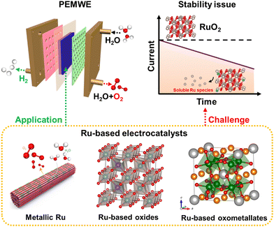
The excessive use of fossil fuels brings about not only resource exhaustion, but also severe environmental issues, such as the greenhouse effect, air contamination, and so on, which are badly in need of storage and conversion technologies for renewable energy.1–4 Green hydrogen, continuously produced by electrochemical water splitting coupled with renewable electricity, is regarded as a potential energy carrier.5–7 Alkaline water electrolyzer (AWE) technology was industrialized for the first time in the 1920s, and then gradually developed into a matured commercial application technology.8,9 However, AWE is subject to high ohmic losses, low working pressure, slow kinetics, and low operating current density.10 These shortcomings were not resolved until the proposal of the concept of solid polymer electrolytes by Grubb.11 Polymer electrolyte membrane water electrolyzers (PEMWEs) can operate with a larger power input range due to the high proton conductivity and lower hydrogen permeability of the membrane, which can ensure their high working current density and hydrogen purity.8,12–15 Moreover, PEMWEs with a compact structure can provide working pressure as high as 350 bar, facilitating the delivery of compressed hydrogen.16,17 However, the cosmically commercial PEMWEs are unfortunately hindered by the electrocatalytic property, especially stability, of anodic catalysts, attributed to the strongly acidic environment and the severe oxidative working conditions.18–20Electrochemical water splitting consists of an anodic oxygen evolution reaction (OER) and a cathodic hydrogen evolution reaction (HER).21–23 The cathodic HER is a two-electron reaction, and is one of the simplest electrochemical reactions and is relatively effortless to achieve. However, the anodic OER is a complex multi-step reaction and involves four-electron transfer, leading to a much higher energy expenditure to surmount the kinetic barrier than HER.24,25 To date, substantial OER catalysts, including alloys, metal oxides, pyrochlores, and perovskites, have been developed to improve anodic electrode kinetics and stability.26–28 However, on account of the thermodynamic unsteadiness of non-noble metal elements under harsh acidic OER operation conditions, the most promising acidic OER catalysts are restricted to precious metals at the present stage.29 As forecasted by the theoretical volcano maps, ruthenium (Ru)-based and iridium (Ir)-based compounds are currently considered the most advanced OER catalysts under strong acidic environments.4,30,31 Note that Ir-based oxides are the most promising candidates to reach the stability standard of PEMWE equipment, owing to their superior acid resistance and oxidation resistance.32–34 Nevertheless, because of the extremely scarce feature of Ir, more than 40 years of global Ir production is required to scale up PEMWE to the terawatt-level.35–37 As the cheapest member of the Pt-related precious metal family, more abundant Ru-based materials deliver relatively superior OER mass activities compared with Ir-related catalysts.38,39 A variety of strategies, including surface engineering,40,41 alloy engineering,42,43 and single atom engineering,44 have been exploited to construct advanced Ru-related OER catalysts. Satisfyingly, an extremely low overpotential of ∼150 mV at 10 mA cm−2 current density can be achieved under strong acidic electrolytes.17,45 Unfortunately, the over-oxidation of RuO2 to soluble RuO4 species would inevitably occur under the highly oxidizing voltage and strong acidic medium,46–48 which calls into question the durability of Ru-related catalysts and leaves the infinite possibility for improvement (Fig. 1).
To date, the dynamic dissolution process of Ru-related acidic OER catalysts has been extensively studied. More importantly, diverse in situ/operando means, including operando X-ray absorption spectroscopy (XAS),49,50in situ ATR-SEIRAS,51,52 operando X-ray photoelectron spectroscopy (XPS),53in situ Raman,54 and isotope labeling measurements,55,56 have been adopted to explore the dissolution behavior of Ru-related derivatives during the acidic OER process. Moreover, theoretical calculations (DFT) have also been conducted to simulate the reaction behavior and process of Ru-related species during the acidic OER process.57–60 These results not only confirm existing theories but also offer new insights into the durability of Ru-related OER catalysts in acidic electrolytes. Despite these achievements, available measures to increase the stability of Ru-related OER catalysts while maintaining their high activity are still relatively limited. Several excellent reviews on similar topics have been published in recent years,26,38 while a comprehensive systematic review of engineering strategies for Ru-related acidic OER electrocatalysts and their corresponding structural and electronic modulation effects is lacking and needed. Therefore, in this review, we would like to emphasize the theoretical and experimental studies of the basic relationship among structure–activity–stability and offer reasonable directions to construct advanced Ru-based catalysts for practical applications. We first discuss the relationship between OER mechanism and activity as well as stability of Ru-related acidic OER catalysts. Thereafter, recent representative efforts on improving the stability of Ru-based catalysts with high activity will also be comprehensively classified and discussed. In the end, we will outline some unresolved questions and provide some personal opinions toward future explorations of Ru-based OER catalysts.
2. Mechanistic studies on Ru-based OER electrocatalysts
Generally speaking, the overall electrocatalytic performances of Ru-based catalysts include activity and stability, which are closely related to the reaction mechanisms. To better analyze the relationship between reaction mechanisms and activity or stability, we summarize them separately.2.1 The relationship between reaction mechanisms and activity
Analogous to other electrochemical reactions, the adsorption energy of reaction intermediates can also be applied to describe the OER activity.18,61–64 In 2007, the oxygen adsorption energy (ΔGO*) was first applied to define the electrocatalytic activity of an OER catalyst by Rossmeisl et al.61 They observed that the binding energy of the relevant OER intermediates on the surfaces of a catalyst (i.e., OH*, O*, OOH*) follows a linear relationship. In other words, the binding energy fluctuation of one oxygen-related reaction intermediate could lead to the binding energy fluctuation of other oxygen-related reaction intermediates, which will inevitably impede optimizing the activity of a catalyst via only improving one reaction step. Fig. 2a shows the theoretical activity of OER as a linear function of the oxygen binding energy (O*), indicating optimal adsorption energy corresponding to the best OER activity and conforming to the above-discussed linear scaling relationship.62 Rossmeisl et al. further identified the linear scaling relationship between the adsorption energy of HOO* and HO* with an approximately constant, which can in reverse define the lowest theoretical activity of an OER catalyst. As presented in Fig. 2b, the relationship between OER activity and the standard free energy of presented a volcano tendency. As a result, the volcano map indicated that an excellent OER electrocatalyst should have moderate bonding energies with the oxygen-related reaction intermediates.
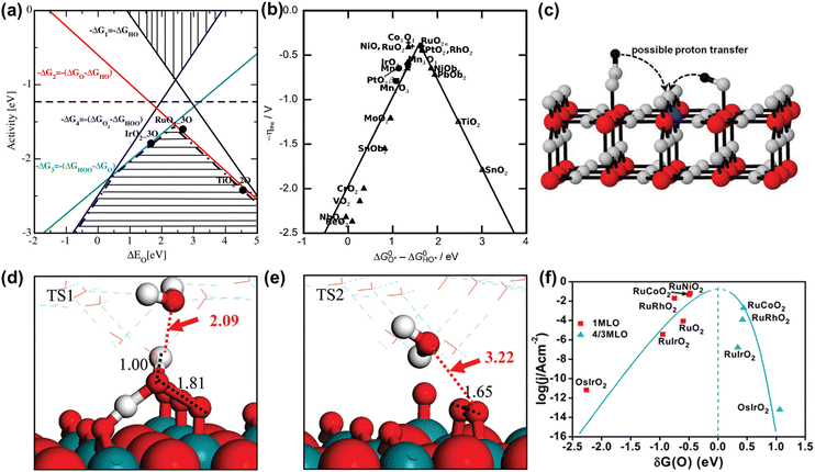 | ||
Fig. 2 (a) OER activity as a function of oxygen binding energy. (b) A volcano-type plot between OER activity and standard free energy change  .62 (c) Schematic illustration of the (110) surface of rutile RuO2 modified by Ni doping.15 (d and e) Transition state (TS) structures of water dissociation (TS1) and surface oxygen coupling (TS2) on the O-terminated phase of RuO2(110).66 (f) The calculated reaction rate of OER on different oxides as a function of δG(O).67 .62 (c) Schematic illustration of the (110) surface of rutile RuO2 modified by Ni doping.15 (d and e) Transition state (TS) structures of water dissociation (TS1) and surface oxygen coupling (TS2) on the O-terminated phase of RuO2(110).66 (f) The calculated reaction rate of OER on different oxides as a function of δG(O).67 | ||
In spite of the restrictions of the linear scaling relationship on enhancing the activity of catalysts to reach the thermodynamic potential limitation of the OER, Halck et al. broke the linear correlation of the adsorption energies by embellishing the oxide surface.65 Conventionally, the coordinatively unsaturated sites (cus) were considered as the active center for the OER. Nevertheless, they found that a dopant like Co or Ni atom located in the bridge site can activate the commonly inactive oxygen atom at the top as a proton donor or receiver, thus lowering the OER overpotential of RuO2 (Fig. 2c).15,65 According to theoretical analysis, the proton donor–acceptor functionality would not only function as a hydrogen acceptor from Ru–OH or Ru–OOH intermediates to reduce their energy state, but also not affect the reaction activity at the cus. More importantly, the additional parameter only influenced two of the three oxygen-related reaction intermediates, thus breaking the linear scaling relationship. Besides, Liu et al. found that the bridging O atom could serve as a proton-acceptor functionality even on pure RuO2, and the H2O tended to attack the aggregation of two surface O groups during the O–O bond formation stage (Fig. 2d and e).66 Furthermore, Chen et al. proved that the electronic structures of bridging oxygen atom sites as proton receivers at the surface of RuO2 played a significant role in the OER activity, which could be adjusted by the introduction of foreign metal atoms (Fig. 2f).67 Therefore, these theoretical works have pointed out guidelines for the rational design of significantly active Ru-related OER catalysts.
In addition, note that catalytic descriptors are important means to analyze the relationship between catalytic behavior and the catalysts, which can also unscramble the activity tendency and find more highly active catalysts.67–72 For example, the d-band theory has become a widely used tool to analyze and forecast the relationship between the electronic properties and activity of catalysts since it was proposed by Hammer and Nørskov.71 Henceforward this theory has been extensively applied to describe bond formation on the surface of catalysts with the diverse filling of the d band. In terms of the interaction between adsorbates and the surface of catalysts, the coupling to a broad metal band will result in broadened and lowered electronic states of the adsorbate (Fig. 3a).72 Generally speaking, the farther the d states are away from the Fermi level, the higher energy is for the antibonding states and the stronger binding energy is between the adsorbate and the surface of catalysts. Moreover, the d-band center position could be adjusted by embellishing the electronic properties of catalysts via diverse ways (doping, alloying, strain engineering, etc.), which can realize the optimal interaction between adsorbates and catalysts to improve OER performance.73–76 Yang et al. revealed that the distance between the d-band center and the Fermi level was larger than RuO2 when Cu was doped into RuO2. This result showed the lowered antibonding energy states and the weakened interaction between adsorbed O species and Ru (Fig. 3b).76
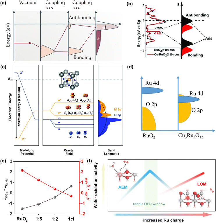 | ||
Fig. 3 (a) Schematic illustration of bond formation at a transition-metal surface. The lower the d states in energy relative to the EF, the more filled the antibonding states and the weaker the adsorption bond.72 (b) The density of states plots of RuO2 and Cu-RuO2, and the corresponding schematic illustration of bond formation between the reaction surface and the adsorbate.76 (c) Physical origin of shifts in constituent ion orbitals for oxides with octahedral oxygen coordination around transition metal ions. The dashed line represents the energy of free vacuum.77 (d) An illustration of how the corresponding position of Ru 4d and O 2p orbitals regulates the reaction mechanism of OER on CuxRuyO12. (e) The computed relative OER overpotentials (ηLOM − ηAEM) vs. the value of εO![[thin space (1/6-em)]](https://www.rsc.org/images/entities/char_2009.gif) 2p − εRu 2p − εRu![[thin space (1/6-em)]](https://www.rsc.org/images/entities/char_2009.gif) 4d for the four structural models.78 (f) Schematic illustration of OER activity and stability of Ru-based catalysts within different reaction routes on the scale of Ru charge.82 4d for the four structural models.78 (f) Schematic illustration of OER activity and stability of Ru-based catalysts within different reaction routes on the scale of Ru charge.82 | ||
Later, the O 2p band center theory was also established. As shown in Fig. 3c, the d band broke up into two eg states at the higher energy level while it broke up into three t2g states at the lower energy level in the field of octahedral coordination.77 There is a strong overlap between eg doublets and O 2p orbitals, which will produce σ-bonding and σ*-antibonding states. However, there was a weak overlap between the t2g triplets and the O 2p orbital, which will generate π-bonds and π*-antibonds. Owing to the translational symmetry of the unit cell, the molecular orbitals turned into bands in oxide crystals, which were expressed as the metal d band and the O 2p band. The bonds formed from the hybridization of metal d bands and O 2p bands could be easily tuned by tuning the electronic properties of catalysts. Our group has investigated the function between OER activity and composition for CuxRuyO12 catalysts via the O 2p band center theory. It can be concluded by the theoretical study that when the O 2p bands were far away from the Fermi level in comparison to the Ru 4d bands, the lattice oxygen was greatly limited and the OER mechanism tended to the adsorbate evolution mechanism (AEM).78 In contrast, when the O 2p band center got close to the Ru 4d orbital center, the lattice oxygen at the catalyst surface was more likely to take part in the reaction and the OER mechanism was inclined to the lattice oxygen evolution mechanism (LOM) (Fig. 3d). The obvious correlation between the computed relative OER overpotentials (ηLOM − ηAEM) and the difference value between O 2p and Ru 4d-band centers (εO![[thin space (1/6-em)]](https://www.rsc.org/images/entities/char_2009.gif) 2p − εRu
2p − εRu![[thin space (1/6-em)]](https://www.rsc.org/images/entities/char_2009.gif) 4d) indicated that the switching between the OER mechanism can be tuned by the amount of Cu or Ni (Fig. 3e).
4d) indicated that the switching between the OER mechanism can be tuned by the amount of Cu or Ni (Fig. 3e).
Over the past decade, beyond d-band and O 2p center theories, extensive works have been done to establish catalytic descriptors to explore the optimal catalysts, including eg orbital occupancy,79 metal-oxygen covalency,80 average O-2p-state energy,62 coordinatively unsaturated metal cation,81 and so on. What calls for special attention is that every above-mentioned descriptor has its limited application domain, and more new effective descriptors need to be established to analyze the Ru-related catalysts. Very recently, Ge et al. reported that the Ru charge was defined as a descriptor to describe the overall performance of Ru-related catalysts (Fig. 3f).82 Moreover, they have managed to regulate the OER mechanism (AEM or LOM) and precisely control the activity and stability under the AEM by changing the chelating atoms around the RuO6 species in MRuOx solid solution.
2.2 The relationship between reaction mechanism and stability
Ru-related materials are widely considered to be extremely unstable when acting as OER catalysts in a strongly acidic medium. During the same OER process, RuO2 will dissolve severely under high overpotential owing to its serious overoxidation, while the dissolution rate of Ru is severalfold quicker than Ru-related oxides.83,84 Over the years, extensive efforts have been made to grasp and understand the degradation mechanism of Ru-related catalysts in the OER, universally attributing to the generation of unstable RuO4 species via the participation of lattice oxygen (Fig. 4a).85 Moreover, the formation and exfoliation of RuO4 species from the electrode can be quantitatively detected by using inductively coupled plasma-mass spectrometry; meanwhile, the presence of ruthenium oxy species in the electrolyte can also be identified by using in situ reflection spectroscopy.86 In addition, Klyukin et al. revealed that the launch of OER and dissolution occurred synchronously for RuO2, suggesting that the dissolution was caused by OER (Fig. 4b).87 It is worth noting that though the dissolved RuO4 species can be relieved via redeposition in the reaction process as presented in Fig. 4a, the durability of Ru-based catalysts would be still greatly deteriorated.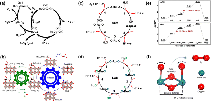 | ||
| Fig. 4 (a) Model for the oxygen evolution and corrosion on Ru and RuO2 electrodes.85 (b) Schematic representation of the found coupling between corrosion and oxygen evolution reaction for the RuO2(110) surface.87 (c) The adsorbate evolution mechanism (AEM). (d) The lattice oxygen evolution mechanism (LOM). (e) The free energy diagrams of the two mechanisms of LOM and AEM for Co-doped RuO2.97 (f) O–O radical coupling promoted by symmetric dual active sites.99 | ||
Furthermore, the durability of Ru-related catalysts is closely related to the OER mechanisms.15,88,89 Over the years, different OER mechanisms in acidic electrolytes have been proposed to uncover the OER process, which is aimed to offer directions for the construction of advanced OER catalysts. Generally, the two most credible hypotheses are known as AEM and LOM in accordance with the origin of the produced O2 molecule.90–92 For the AEM in acidic media, all the oxygen atoms in the produced O2 molecules are derived from the adsorbed water, and such an OER process is made up of four synchronous proton–electron transfer procedures as presented in Fig. 4c. In terms of the LOM, it involves the surface lattice oxygen redox. That is, the excited lattice oxygen atoms in catalysts will take part in the water oxidation steps, and finally the oxygen atoms in the generated O2 derive from both adsorbed water and the lattice of Ru-based catalysts as shown in Fig. 4d. Excitingly, the formation of the O![[double bond, length as m-dash]](https://www.rsc.org/images/entities/char_e001.gif) O bond is not accompanied by the generation of Ru–OOH, and therefore breaks the scaling relationships.62,93,94 Significantly, the surface of Ru-related catalysts via the AEM process is deemed to be stable with only valence variation of the active sites, while the surface is unstable through the LOM process with the generation of activated lattice oxygen.95 This result is due to the rate of oxygen vacancy (Ov) formation being generally faster than that of Ov refilling during the LOM process. Meanwhile, the exfoliation of adjacent cations would occur on the surface of catalysts to achieve the compensated charge balance.17 Such results can be confirmed by the higher dissolution rate of electrochemically produced RuO2 with enriched defects than that of thermally formed RuO2.96 Nonetheless, whether the involvement of lattice oxygen indeed brings about inferior durability for Ru-based catalysts remains open. On the contrary, Tian et al. reported a Co-doped RuO2 catalyst with enriched oxygen vacancies with an ultra-high acidic OER performance obeying the LOM mechanism. Moreover, they thought that the greatly enhanced durability of Co-doped RuO2 was closely related to the LOM pathway, and the over-oxidation of Ru to dissolved RuO4 species was due to the participation of the oxygen vacancy (Fig. 4e).97
O bond is not accompanied by the generation of Ru–OOH, and therefore breaks the scaling relationships.62,93,94 Significantly, the surface of Ru-related catalysts via the AEM process is deemed to be stable with only valence variation of the active sites, while the surface is unstable through the LOM process with the generation of activated lattice oxygen.95 This result is due to the rate of oxygen vacancy (Ov) formation being generally faster than that of Ov refilling during the LOM process. Meanwhile, the exfoliation of adjacent cations would occur on the surface of catalysts to achieve the compensated charge balance.17 Such results can be confirmed by the higher dissolution rate of electrochemically produced RuO2 with enriched defects than that of thermally formed RuO2.96 Nonetheless, whether the involvement of lattice oxygen indeed brings about inferior durability for Ru-based catalysts remains open. On the contrary, Tian et al. reported a Co-doped RuO2 catalyst with enriched oxygen vacancies with an ultra-high acidic OER performance obeying the LOM mechanism. Moreover, they thought that the greatly enhanced durability of Co-doped RuO2 was closely related to the LOM pathway, and the over-oxidation of Ru to dissolved RuO4 species was due to the participation of the oxygen vacancy (Fig. 4e).97
Based on the AEM mechanism, the binding energy of different reaction intermediates is linearly correlated by the so-called scaling relationships, thus resulting in a smallest theoretical overpotential of 0.37 V, which essentially limits catalytic activity.98 In order to avoid the limitation of the theoretical overpotential in the AEM and the poor stability due to the participation of oxygen vacancies in the LOM, Lin et al. reported an advanced acidic OER catalyst with atomically dispersed Ru on α-MnO2, involving only *O and *OH species serving as intermediates and allowing the O–O radical to produce O2 without the formation of oxygen vacancies (Fig. 4f).99 Beyond expectation, such a Ru-based catalyst can exhibit superior activity as low as 161 mV at 10 mA cm−2 and remarkable durability without overpotential variation over 200 h. All in all, enhancing stability without sacrificing activity needs reducing the bulk oxygen diffusion rate and surface exchange kinetics whether following the LOM or bypassing the AEM and LOM.
3. Attempts to enhance the OER performance of Ru-based electrocatalysts
To date, various Ru-related materials have been explored for enhanced acidic OER performance. Table 1 presents a representative list of the reported Ru-based acidic OER catalysts. This section provides a review of the progress in Ru-based materials, including metallic Ru, Ru-based oxides, and Ru-based oxometallates, toward acidic OER and highlights the mechanism of improved performance.| Classification | Catalysts | Electrolyte | Overpotential (mV) at 10 mA cm−2 | Tafel slope (mV dec−1) | Stability | Ref. |
|---|---|---|---|---|---|---|
| Metallic Ru | Faceted Ru branched nanoparticles | 0.1 M HClO4 | 180 | 52 | 4 h@10 mA cm−2 | 100 |
| L-Ru | 0.5 M H2SO4 | 202 | 69.6 | 10 h@10 mA cm−2 | 103 | |
| Co-RuIr | 0.1 M HClO4 | 235 | 66.9 | 25 h@10 mA cm−2 | 42 | |
| RuMn | 0.5 M H2SO4 | — | — | 720 h@10 mA cm−2 | 107 | |
| RuIr@CoNC | 0.5 M H2SO4 | 223 | 45 | 40 h@10 mA cm−2 | 110 | |
| Nicluster-Ru NWs | 0.5 M H2SO4 | 205 | — | — | 111 | |
| Ru/RuS2 | 0.5 M H2SO4 | 201 | 47.2 | 3000 cycles | 112 | |
| Ru@IrOx | 0.05 M H2SO4 | 282 | 69.1 | 24 h@10 mA cm−2 | 113 | |
| Ru@MoO(S)3 | 0.5 M H2SO4 | 226 | 51 | — | 114 | |
| Ru–N–C | 0.5 M H2SO4 | 267 | 52.6 | 30 h@1.5 V vs. RHE | 118 | |
| Ru/Co-N-C | 0.5 M H2SO4 | 232 | — | 20 h@10 mA cm−2 | 119 | |
| Ru/MnO2 | 0.1 M HClO4 | 161 | 29.4 | 200 h@10 mA cm−2 | 99 | |
| Ru1-Pt3Cu | 0.1 M HClO4 | 220 | — | 28 h@10 mA cm−2 | 44 | |
| Ru-based oxides | RuO2 NSs | 0.5 M H2SO4 | 199 | 38.2 | 20![[thin space (1/6-em)]](https://www.rsc.org/images/entities/char_2009.gif) 000 s@10 mA cm−2 000 s@10 mA cm−2 |
122 |
| UfD-RuO2/CC | 0.5 M H2SO4 | 179 | 36.9 | 20 h@1.42 V vs. RHE | 123 | |
| Ru-UiO-67-bpydc | 0.5 M H2SO4 | 200 | 78.3 | 140 h@50 mA cm−2 | 54 | |
| RuO2-WC NPs | 0.5 M H2SO4 | 347 | 88.5 | 10 h@10 mA cm−2 | 124 | |
| Ru@V-RuO2/C HMS | 0.5 M H2SO4 | 176 | 45.6 | 10k cycles | 125 | |
| RuNi2©G-250 | 0.5 M H2SO4 | 227 | 65 | 24 h@10 mA cm−2 | 126 | |
| RuO2/D-TiO2 | 0.5 M H2SO4 | 180 | 43 | — | 127 | |
| RuO2/(Co,Mn)3O4 | 0.5 M H2SO4 | 270 | 77 | 24 h@10 mA cm−2 | 128 | |
| Au@Pt@RuOx nanowires | 0.1 M HClO4 | 215 | 65.5 | 40 h@10 mA cm−2 | 129 | |
| a/c-RuO2 | 0.1 M HClO4 | 205 | 48.6 | 60 h@10 mA cm−2 | 49 | |
| Rh-RuO2 | 0.5 M H2SO4 | 161 | 45.8 | 700 h@50 mA cm−2 | 56 | |
| Re0.06Ru0.94O2 | 0.1 M HClO4 | 190 | 45.5 | 200 h@10 mA cm−2 | 51 | |
| 75-H-RuO2 | 0.5 M H2SO4 | 200 | 71 | 20 h@10 mA cm−2 | 147 | |
| B-RuO2 | 0.5 M H2SO4 | 200 | 55 | 12 h@10 mA cm−2 | 149 | |
| Si-RuOx@C | 0.5 M H2SO4 | 220 | 53 | 100 h@10 mA cm−2 | 152 | |
| SS Pt-RuO2 HNSs | 0.5 M H2SO4 | 228 | 51 | 100 h@10 mA cm−2 | 153 | |
| S-RuFeOx | 0.1 M HClO4 | 187 | 40 | 50 h@1 mA cm−2 | 133 | |
| Ru0.85Zn0.15O2−δ | 0.5 M H2SO4 | 190 | 42 | 50 h@10 mA cm−2 | 136 | |
| SnRuOx | 0.5 M H2SO4 | 194 | 38.2 | 100 h@250 mA cm−2 | 82 | |
| Li0.52RuO2 | 0.5 M H2SO4 | 156 | 83.3 | 70 h@10 mA cm−2 | 45 | |
| Ru-based oxometallates | Y2Ru2O7−δ | 0.1 M HClO4 | 190 | 55 | 8 h@1 mA cm−2 | 154 |
| Mo-YRO | 0.1 M HClO4 | 240 | 40.45 | 30 h@10 mA cm−2 | 158 | |
| Sr2(Ru0.5Ir0.5)O4 | 0.1 M HClO4 | 8.06 mA cm−2 @ 1.55 V vs. RHE | 47 | 24 h@10 mA cm−2 | 161 | |
| SrRu0.5Ir0.5O3 | 0.5 M H2SO4 | 185 | 35 | 50 h@10 mA cm−2 | 162 | |
| Sr0.90Na0.10RuO3 | 0.1 M HClO4 | 170 | — | — | 163 | |
| CaCu3Ru4O12 | 0.5 M H2SO4 | 171 | 40 | 24 h@10 mA cm−2 | 138 | |
| Ru chalcogenides/boride | a-RuTe2 PNRs | 0.5 M H2SO4 | 245 | — | — | 164 |
| RuB2 | 0.5 M H2SO4 | 223 | 39.8 | 10 h@10 mA cm−2 | 165 |
3.1 Optimization of metallic Ru
To improve the overall OER catalytic performance of Ru metals in acidic media, efficient strategies need to be adopted to increase their accessible active sites and resistance to corrosion, such as facet engineering, strain engineering, alloying engineering, synergistic effects, and single atom engineering.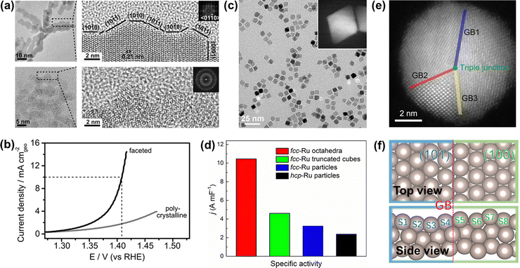 | ||
| Fig. 5 (a) TEM image of faceted Ru branched nanoparticles (top) and polycrystalline Ru nanoparticles (bottom). (b) Potentiodynamic curves of the OER performance of faceted Ru branched nanoparticles and polycrystalline Ru nanoparticles.100 (c) TEM image of the Ru octahedral nanocrystals and (inset) HAADF-STEM image of an individual Ru octahedron. (d) Summary of the specific activity of different Ru catalysts toward oxygen evolution.41 (e) HAADF-STEM images of Ru nanoparticles with grain boundaries. (f) Atomic model of Ru(101)–Ru(100) grain boundaries.103 | ||
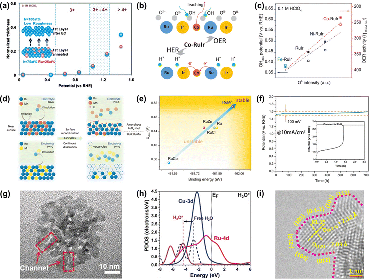 | ||
| Fig. 6 (a) Relationships between the surface oxidation state of annealed Ru0.5Ir0.5 and Ir skeleton formation during OER.105 (b) Schematic of the OER mechanism on the Co-RuIr electrocatalyst in acidic media. (c) Relationships between OI− species concentration and OH desorption (OHdes) potential, and OER activity.42 (d) Schematic of surface reconstruction of RuMn (top) and dissolution of unstable Ru-based alloys (below) in acidic media during CV cycles. (e) The relationships between durability and binding energy (Ru). (f) The CP curve of RuMn and commercial RuO2 at 10 mA cm−2.107 (g) High-magnification TEM image of RuCu NSs. (h) The PDOS of H2O adsorption on RuCu NSs.108 (i) HRTEM image of RuIr nanocrystals (atomic steps are indicated with pink dotted lines).110 | ||
Except for the Ir-armour structures, the introduction of nonprecious transition metals is able to not only further improve catalytic activity but also greatly reduce the consumption of noble metals. For instance, Shan et al. reported a Co-RuIr catalyst with a small overpotential of 235 mV at 10 mA cm−2 for OER in acidic media, much superior to that of RuIr (344 mV), which was due to the increased concentration of OI− species caused by the dealloying of the Co element, greatly enhancing OER catalytic activity (Fig. 6b).42 In addition, Ni-RuIr and Fe-RuIr electrocatalysts were also prepared to build the composition–activity relationship, showing that both OH− desorption peak positions and OER activity are linear with the intensity of OI− species (Fig. 6c), which suggested that the concentration of oxygen species predicted the trend of OER activity.
Notably, although dealloying-caused surface reconstruction will complicate the reaction sites, it can be a win–win situation in terms of increased overall catalytic performance if utilized properly. For example, An et al. reported that a series of Ru-based alloys were prepared by doping with Mn, Zn, Cr, and Co and then subjected to dealloying treatment by the CV cycle test.107 Thereinto, RuMn showed superior anti-corrosion and anti-oxidation properties during the acidic OER process while other Ru-based alloys dissolved quickly in the process of dealloying treatment (Fig. 6d). This was because there was a controllable surface reconstruction process during the continuous CV cycle test along with the leaching of Mn species and the formation of an amorphous RuOx surface. Theoretical calculations indicated that the strong binding energy of Ru in the RuMn alloy could cause a highly stable structure (Fig. 6e). More attractively, the RuMn alloy catalyst exhibited a very competitive stability over 720 h at 10 mA cm−2 (Fig. 6f).
In addition, alloying engineering coupled with other strategies can further significantly improve the catalytic performance of Ru-related catalysts. For example, Huang's group reported channel-enriched RuCu nanosheets as acidic OER catalysts with enhanced electrochemical performance (Fig. 6g).108 DFT calculations indicated that the channel-enriched structures could not only activate the electron on the catalyst surface, but also lead to obvious lattice distortion around the channel area, thus greatly reducing the energy consumption of bond-dissociation for intermediates during the acidic OER process (Fig. 6h). They also reported Mn-doped ultrathin Ru nanosheet branches as a significantly active and stable catalyst toward acidic water splitting.109 Xu et al. reported an OER catalyst comprising atomic-step enriched RuIr nanoparticles supported on the novel MOF-derived carbon (Fig. 6i), delivering a low overpotential of 223 mV and remarkable durability without notable degradation up to 40 h at 10 mA cm−2 in an acidic electrolyte.110 Detailed experimental characterization coupled with theoretical calculations indicated that a strong chemical bond was formed between the pyrrolic-N sites on the skeleton and RuIr nanocrystals to provide a good solubility resistance during the acidic OER. Meanwhile, the unique atomic steps could fully expose the active sites and optimize the rate-determining step of OER, thus improving the catalytic activity. All in all, alloying engineering can enhance both activity and stability of Ru-based metal catalysts via the effective optimization of the electronic structure.
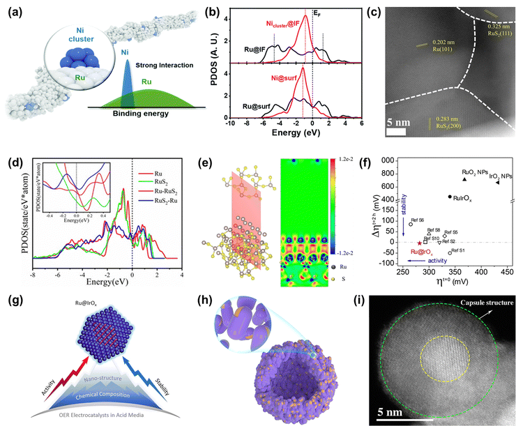 | ||
| Fig. 7 (a) The schematic diagram of the diluted Ni nanocluster on Ru nanowires. (b) The PDOS comparison of Ru-4d and Ni-3d bands at the interface and surface.111 (c) ac-STEM image of Ru/RuS2. (d) PDOS of surface Ru sites on as-built models. (e) Charge density difference of the two-dimensional slice on the RuS2-Ru model.112 (f) Stability–activity plot for various OER electrocatalysts. (g) Diagram of the core–shell Ru@IrOx heterostructure nanocrystal.113 (h) Schematic diagram of the nano-capsule structure of Ru@MoO(S)3. (i) HAADF-TEM image of Ru@MoO(S)3.114 | ||
Among the various heterostructures, the core–shell structure can protect the core from oxidation and corrosion more effectively, guaranteeing higher stability. Recently, Shan and co-workers reported a core–shell heterostructured OER catalyst composed of a partially oxidized Ir shell and a greatly disordered and strained Ru core (Ru@IrOx) that displayed an overpotential of 282 mV at 10 mA cm−2 and good stability over 24 h under acidic conditions, much superior to that of RuIr oxide alloy (RuIrOx) nanocrystals (Fig. 7f).113 They found that the charge was greatly redistributed at the Ru-core and IrOx-shell interface, which increased the valence state of Ir and reduced the valence state of Ru to form favorable surface chemical states, therefore increasing the catalytic activity. Also, the improved stability was due to the synergistic effect from the unique core–shell heterojunction as well as induced charge redistributions (Fig. 7g). Detailedly, XPS and HAADF-STEM images of Ru@IrOx after the test indicated that the stable chemical states contributed to preventing the generation of dissolvable high-valence intermediate species and the core–shell nanostructure protected active Ru sites from loss in acidic media. In addition to the protection of the Ir-based shell, Ru encapsulated by a transition metal-based shell is demonstrated to be a cheap and effective strategy to design highly advanced Ru-based catalysts. Mu's group designed and prepared a core–shell structured catalyst Ru@MoO(S)3 (Fig. 7h and i), which displayed a high catalytic performance in the acidic OER process, owing to not only Ru acting as a highly active site but also due to it being protected by the MoO(S)3 shell.114 Therefore, designing heterostructures can not only achieve enhanced activity through charge redistribution at interfaces but also realize improved stability through strong interactions at the heterogeneous interfaces and also through the good protection from the stable enclosure.
Recently, Cao and co-workers prepared atomically dispersed Ru1-N4 moieties immobilized on a N-carbon substrate (Ru–N–C). When Ru–N–C was used as an acidic OER catalyst, it showed a low overpotential of 267 mV at 10 mA cm−2 with persistent and stable working over 30 h.118 They found that there was reversible dynamic adsorption/desorption of a single oxygen atom on the Ru1-N4 sites with the formation of O-Ru1-N4, and the generation of a higher valence state of Ru during the in situ operation through operando XAS and SR-FTIR (Fig. 8a and b). DFT results indicated that more charge donations occurred from the Ru 4d state to the N 2p state, further suggesting that the formation of O-Ru1-N4 sites contributed to OER activity and stability (Fig. 8c). Further, Rong et al. regulated the electronic structure and catalytic performances of the atomically anchored Ru active sites by the introduction of another atomically dispersed Co site (Fig. 8d).119 Namely, they prepared atomical Ru and Co dual-sites dispersed on N-carbon (Ru/Co-N-C), exhibiting a small overpotential of 232 mV and remarkable stability over 20 h with stable activity for OER at 10 mA cm−2 in an acidic medium. DFT calculations demonstrated that the incorporation of Co-N4 sites into Ru/Co-N-C not only significantly tuned the electronic properties of Ru sites through increasing Ru–O covalency but also promoted the electron transfer from C/N atoms to Ru. Therefore, the binding energy of reaction intermediates was greatly optimized to enhance OER activity and the electron around Ru-N4 was well redistributed to enhance the resistance to corrosion of Ru/Co-N-C (Fig. 8e and f).
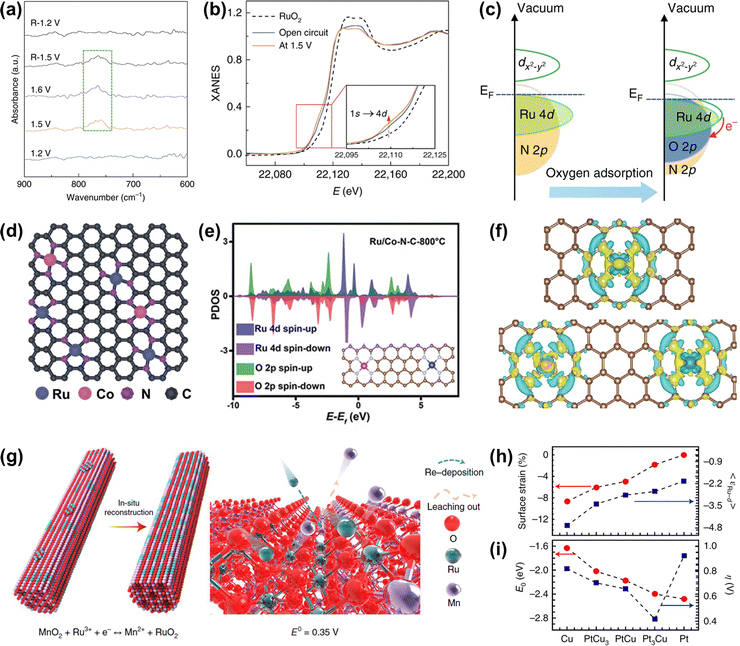 | ||
| Fig. 8 (a) Operando SR-FTIR spectroscopy measurements for Ru–N–C during the acidic OER. (b) Operando XANES spectra for Ru–N–C during OER. Inset: Magnified pre-edge XANES region. (c) Schematic illustration of the effect of oxygen adsorption on the electronic structure of Ru–N–C.118 (d) Proposed structural model of Ru/Co-N-C. (e) PDOS of Ru/Co-N-C (the inset is the corresponding model). (f) Differential charge density at the atomical Ru centers between Ru and neighboring C/N atoms in Ru–N–C (top) and Ru/Co-N-C (below).119 (g) Schematic illustration of the in situ reconstruction process of Ru/MnO2. (h) In-plane lattice contraction relative to the Pt (111) pristine surface (red circles) and the corresponding d-band center εRu−d of Ru1 (blue squares).99 (i) Corresponding adsorption energy EO of the oxygen atoms (red circles) and η (blue squares).44 | ||
Note that although the carbon skeleton contributes to anchoring and protecting single atoms from unwanted agglomeration, the thermodynamical property of carbon materials under oxidation potential is not stable, which will result in the configuration damage of single atoms.30 Fortunately, it has been demonstrated that Sb/Ti/Sn/Ge/Mo/W-based oxides possess strong resistance to oxidation and dissolution in the acidic OER process.120 Moreover, γ-MnO2 can work as an acidic OER catalyst over 8000 h, though tested under low current density, making it act as a potential acid-resistant support.121 If the Ru atoms can be coupled well with these acid-stable supports, it will not only reduce the consumption of Ru elements but also improve the stability of single atom Ru-related catalysts. For example, Lin et al. reported an advanced OER catalyst with Ru atom chains anchored on α-MnO2 (Ru/MnO2) through a cation exchange method.99 Time-dependent elemental analysis revealed that the in situ dynamic cation exchange reaction occurred during the OER process. This dynamic reaction not only led to the formation of Ru atom arrays but also preserved the catalyst from metal-leaching-induced dissolution (Fig. 8g). Owing to the shorter interatomic Ru–Ru distance in Ru/MnO2, such catalyst followed the oxide path mechanism to ensure high activity as discussed above in Fig. 4f. As a consequence, Ru/MnO2 displayed an overpotential as low as 161 mV at 10 mA cm−2 and excellent long-term stability of more than 200 h under acidic OER conditions.
Other than non-noble transition metal oxides, noble metal-based skeletons are also promising supports to atomically anchor and disperse Ru atoms, except for the limitation of high price. Yao et al. reported a group of PtCux/Pt skin core–shell structures with embedded Ru atoms on account of the epitaxial growth of nano-island formation of PtCux from the Cu nanowires.44In situ XAFS measurements indicated that the valence state of Ru1 was almost unchanged during the OER process. During the acid etching and electrochemical leaching process, the gradual release of compressive strain in comparison to pristine Pt was conducive to increasing the Ru d-band center to approach the Femi level, resulting in the well-optimized oxygen adsorption energy (EO), which ultimately leads to an inverse volcano-type relationship between the OER activity and the lattice constant (Fig. 8h and i). As a result, the best Ru1-Pt3Cu catalyst displayed an overpotential of 220 mV at 10 mA cm−2 and remarkable long-term stability, much better than that of commercial RuO2. The enhanced stability was attributed to the occurrence of electron transfer from Pt to Ru as revealed by in situ XANES, which protected the Ru atoms from overoxidation and accompanying dissolution. Thus, single-atom engineering can not only reduce the consumption of precious Ru metal, but also endow single Ru atoms with unique coordination environments to ensure their superior overall acidic OER performances.
3.2 Optimization of Ru-based oxides
Strategies for improved performance of Ru-based oxides including morphology control, heterostructure construction, doping, substituting, and so forth have been confirmed to be effective.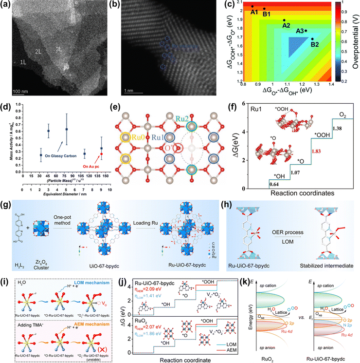 | ||
| Fig. 9 (a) STEM images of RuO2 NSs at a lower magnification. (b) Atomic STEM images of RuO2 NSs. (c) Two-dimensional volcano plot constructed using the descriptors of ΔGO* − ΔGOH* and ΔGOOH* − ΔGO*.122 (d) OER mass activities of different thermally oxidized RuO2 particle masses.63 (e) The top view of the defective RuO2 structure. (f) The calculated free-energy profiles of OER on the (a) Ru0, (b) Ru1, and (c) Ru2 sites.123 (g) Scheme of the preparation of the Ru-UiO-67-bpydc catalyst. (h) The stability of the Ru intermediate in the MOF-anchored Ru oxide during the acidic OER by the LOM pathway. (i) Schematic illustration of the intermediate model in CV peaks with and without TMA+. (j) Gibbs free energy illustration by Ru-UiO-67-bpydc and RuO2 catalysts during the OER process by the AEM or LOM pathway. (k) Schematic molecular orbital energy diagram for Ru-UiO-67-bpydc and RuO2 toward the acidic OER.54 | ||
If the size of Ru oxides can be downsized to the atomic level, the catalytic performances will be significantly improved, due to the maximized atom utilization efficiency and unique electronic structure. Very recently, Yao et al. prepared an acidic OER catalyst of atomically dispersed Ru oxide on UiO-67-bpydc (Ru-UiO-67-bpydc) with robust Ru–N bonds through an effective metal-organic framework anchored strategy (Fig. 9g).54 They thought that the sturdy coordinating pyridine ligands and the strong interaction between Ru oxide and the metal-organic framework could induce the motivated LOM pathway and stabilize the dissolvable high-valence oxygen-vacancy intermediate simultaneously, thus leading to the synchronously improved overall catalytic performance of Ru oxides (Fig. 9h). As a consequence, Ru-UiO-67-bpydc displayed a low overpotential of 200 mV and excellent stability without activity and structure degeneration over 115 h at 10 mA cm−2 under acidic conditions. The experimental results confirmed that the lattice oxygen was involved in the OER process via the LOM pathway (Fig. 9i and j). DFT calculations indicated that the robust Ru–N bonds led to the Ru d-band center far away from the Fermi level but the O 2p-band center close to the Fermi level, definitely enhancing the catalytic performances of Ru oxides (Fig. 9k). Therefore, an important way to improve the catalytic performance of Ru-based oxides is to design the structure of nanomaterials reasonably, so as to realize effective utilization of precious metals.
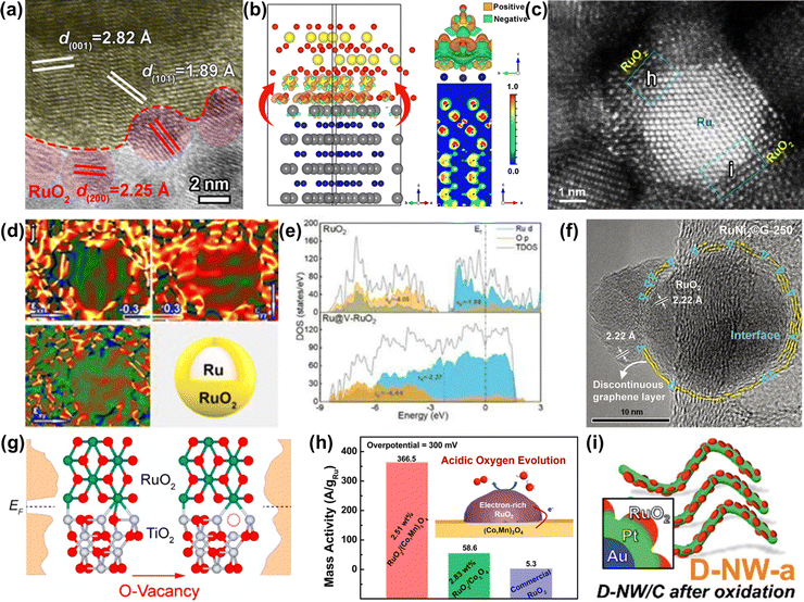 | ||
| Fig. 10 (a) HRTEM image of RuO2-WC NPs. (b) Optimized configuration of the RuO2-WC interface derived from first-principles calculations.124 (c) Aberration corrected HAADF-STEM and (d) the corresponding strain maps of Ru@V-RuO2/C HMS. (e) The partial density of states projected on the p orbits of O atoms for RuO2 (upper) and Ru@V-RuO2 (bottom).125 (f) HRTEM image of RuNi2©G-250 with a unique interface between RuO2 and graphene.126 (g) Partial density of states for RuO2/TiO2 and RuO2/D-TiO2 interfaces.127 (h) Schematic illustration and mass activity of RuO2/(Co,Mn)3O4.128 (i) Schematic illustration of Au@Pt@RuOx.129 | ||
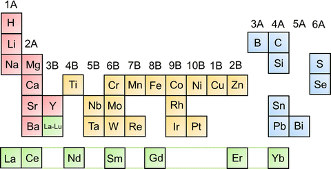
In addition to the strategies discussed above, another effective strategy is incorporating foreign metal atoms, such as alkali metals (Li,45 Na,49etc.), transition metals (Ti,130 Cr,131 Mn,132 Fe,133 Ni,55 Co,134 Cu,135 Zn,136etc.), main group metals (Mg,137 Ca,138 Sr,139etc.), noble metals (Pt,140 Rh,56 Ir,141etc.), acid-insoluble metals (Sn,82 Pb,142etc.), and rare earth metals (La,143 Ce,144 Y,145 Er,146etc.), and non-metallic elements (H,147 C,148 B,149 S,150 Se,151 Si,152etc.) with Ru through doping and substitution or forming Ru-related pyrochlores and perovskites to greatly enhance the OER performances (Fig. 11). This part will be divided into the following aspects: cation doping, anion codoping, anion and cation codoping, and solid solution oxides.
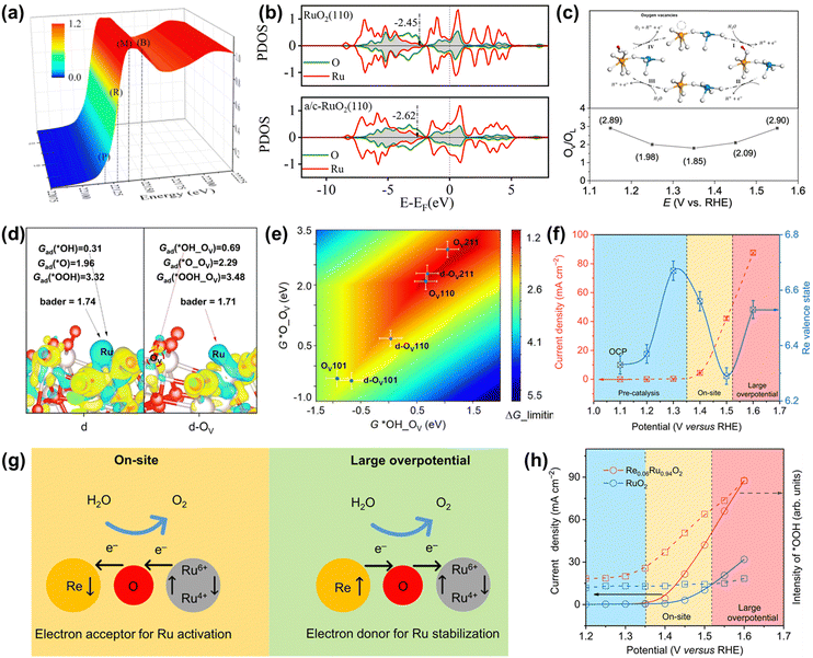 | ||
| Fig. 12 (a) 3D plot of the operando Ru K-edge XANES spectrum of schematic illustration of a/c-RuO2. (b) PDOS of d-bands of active Ru for RuO2 and a/c-RuO2.49 (c) Variation of the OV/OL ratio from quasi in situ XPS measurements on Rh-RuO2/G. (d) Charge density difference analysis for the d and d-OV slab. (e) A two-dimensional activity map for the LOM-OVSM mechanism based on OER.56 (f) Change in the Re valence state and OER current as a function of the applied potential. (g) Schematic for dynamic electron transfer in Re0.06Ru0.94O2. (h) Potential dependence of the band intensity of characteristic vibration adsorption of surface-adsorbed *OOH.51 | ||
Unusually, Wang et al. recently reported an OER catalyst of Rh-doped RuO2 on graphene (Rh-RuO2/G), whose OER mechanism followed the lattice oxygen mediated mechanism-oxygen vacancy site mechanism (LOM-OVSM).56 As a result, Rh-RuO2/G delivered an ultralow overpotential of 161 mV at 10 mA cm−2 and remarkable long-term durability without obvious activity change over 700 h at 50 mA cm−2. Experimental characterization analysis coupled with DFT calculations confirmed that the emerging oxygen species during the OER process were reversible, which greatly improved both intrinsic activity and crystal structure stability (Fig. 12c and d). DFT calculations indicated that the oxygen vacancies coupled with Ru–O–Rh active sites made Rh-RuO2/G follow the LOM-OVSM. In addition, the generation of *O on Ru–O–Rh active sites was the rate-determining step of Rh-RuO2/G, which broke the barrier limitation (*OOH) of the AEM (Fig. 12e).
In addition to regulating the reaction mechanism, the electron transport form can also be adjusted to improve the overall catalytic performance. Very recently, Jin et al. found that the electron accepting–donating process in Re-doped RuO2 (Re0.06Ru0.94O2) was dynamic, completely different from the traditional static electron redistribution caused by the dopant, which significantly improved both activity and stability.51 Operando XAS characterization indicated that the electron transfer between Re and Ru sites was highly correlated to the operating potential along with dynamic role change of the Re site (Fig. 12f). As detailedly shown in Fig. 12g, the Re sites accept electrons from Ru sites at the on-site potential to enhance the catalytic activity of Ru sites. In contrast, the electrons are transferred from Re atoms to Ru sites at a large overpotential to avoid the overoxidation of Ru and boost the stability of Ru sites. Moreover, in situ characterization and DFT calculations confirmed that the unique dynamic electron transfer promoted the transformation of the reaction pathway on Re0.06Ru0.94O2 from LOM to AEM and optimized the binding energies of reaction intermediates, thus increasing catalytic performances (Fig. 12h). Moreover, aberration-corrected HAADF-STEM images and XAFS measurements of Re0.06Ru0.94O2 after OER indicated that there was no aggregation or reconstruction of Re single atoms and no change of the valence state and coordination environment of Ru and Re atoms after the OER process. Thus, cation doping is demonstrated to be an effective way to optimize the electronic structures of Ru-based oxides to regulate the OER pathway.
![[thin space (1/6-em)]](https://www.rsc.org/images/entities/char_2009.gif) 000 cycles in an acid electrolyte.152 Theoretical calculations revealed that the Si dopant not only optimized the binding energy of oxygen-related intermediates but also served as an electron receiver from Ru to enhance the resistance to overoxidation, thus improving both activity and stability (Fig. 13d). Although great enhancements of activity and stability are achieved by using anion doping, the change of the doped anion atoms during the OER process requires further detailed research.
000 cycles in an acid electrolyte.152 Theoretical calculations revealed that the Si dopant not only optimized the binding energy of oxygen-related intermediates but also served as an electron receiver from Ru to enhance the resistance to overoxidation, thus improving both activity and stability (Fig. 13d). Although great enhancements of activity and stability are achieved by using anion doping, the change of the doped anion atoms during the OER process requires further detailed research.
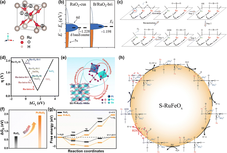 | ||
| Fig. 13 (a) Structural illustration of proton and electron co-doped RuO2.147 (b) Schematic diagram of d-band center change of the Ru-bri site of B/RuO2. (c) The schematic diagram of BO2 migration during OER.149 (d) The calculated overpotential for Si-RuOx@C in the “volcano” plot of overpotential versus ΔG2 (ΔG2 = ΔGOH* − ΔGO*).152 (e) Structural illustration of SS Pt-RuO2 HNSs. (f) The calculated dissociation energy of *O in RuO2 and Pt-RuO2, respectively. (g) The free energy profiles of the OER process on RuO2 and SS Pt-RuO2 HNSs under the applied overpotential of 0 and 1.23 V (RHE), respectively.153 (h) Schematic illustration of the reaction mechanism toward acidic OER on S-RuFeOx.133 | ||
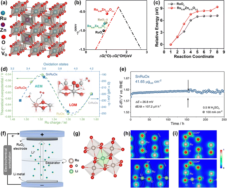 | ||
Fig. 14 (a) Crystal structure of rutile Ru0.85Zn0.15O2−δ. (b) The kinetic barrier for breaking the Ru–O bond in RuO2(110) and Ru0.85Zn0.15O2−δ. (c) The calculated negative overpotential (−ηOER) plotted against the descriptor of ΔG(O*) − ΔG(*OH) on different catalysts.136 (d) The variation of apparent overpotential at 10 mA![[thin space (1/6-em)]](https://www.rsc.org/images/entities/char_2009.gif) cm−2 with Ru oxidation states. (e) Chronopotentiometry curve of the SnRuOx nanocatalyst operated at 100 mA cm−2 with Ru oxidation states. (e) Chronopotentiometry curve of the SnRuOx nanocatalyst operated at 100 mA![[thin space (1/6-em)]](https://www.rsc.org/images/entities/char_2009.gif) cm−2 during the 250 cm−2 during the 250![[thin space (1/6-em)]](https://www.rsc.org/images/entities/char_2009.gif) h test.82 (f) Schematic illustration of the preparation of lithium intercalated RuO2. (g) RuO6 octahedron after lithium intercalation. (h) The charge density distribution of O* absorbed on the (110) surface of RuO2 (up) and Li0.5RuO2 (down). (i) The charge density distribution of OOH* absorbed on the (110) surface of RuO2 (up) and Li0.5RuO2 (down).45 h test.82 (f) Schematic illustration of the preparation of lithium intercalated RuO2. (g) RuO6 octahedron after lithium intercalation. (h) The charge density distribution of O* absorbed on the (110) surface of RuO2 (up) and Li0.5RuO2 (down). (i) The charge density distribution of OOH* absorbed on the (110) surface of RuO2 (up) and Li0.5RuO2 (down).45 | ||
Different from the previously reported solid solution with the Ru cations replaced by foreign atoms, a unique Li0.52RuO2 solid solution oxide with Li ions intercalated into the octahedral interstices composed of six adjacent O atoms was synthesized by Qin et al. via the electrochemical lithiation process (Fig. 14f and g).45 The Li ions intercalated into the lattice interstices induced the electron redistribution and local lattice distortion of RuO2, reducing the valence state of Ru with the generation of the robust Li–O–Ru local structure, which prevented the dissolution of Ru and improved the stability. Note that the surface structural distortion caused by intrinsic lattice strain could motivate the dangling O atom surrounding the Ru active site to act as a proton receiver, which effectively anchored the OOH* to greatly improve the catalytic activity of Li0.52RuO2 solid solution oxide for acidic OER (Fig. 14h and i). The constructed Li0.52RuO2 delivered a record activity of 156 mV at 10 mA cm−2 and good stability with persistent operation for 70 h without obvious overpotential change. All in all, the Ru-based solid solution oxides, whether the M intercalates into the octahedral interstices or substitutes the position of Ru, deliver improved catalytic performance through the formation of unique M–O–Ru bonds.
3.3 Optimization of Ru-based oxometallates
Ru-based oxometallates, including pyrochlore- and perovskite-type ruthenates, have attracted widespread attention with their low Ru content and remarkable catalytic performances in acidic OER. The most effective strategy to improve the performance of pyrochlore- and perovskite-type ruthenates is substitution.To expand acid-stable Ru-based catalysts with high activity for OER, Kim et al. produced a pyrochlore yttrium ruthenate (Y2Ru2O7−δ) by the sol–gel method, showing a low onset overpotential of 190 mV and high stability over 8 h at 1 mA cm−2 under acidic conditions.154 The overall enhanced catalytic performance was due to the lowered Ru valence state and the reduced overlapped energy band center between Ru 4d and O 2p bands (Fig. 15a and b). Moreover, the superior structural stability of Y2Ru2O7−δ during the acidic OER process was confirmed by the XPS, XAS and PXRD results. Recently, Hubert et al. prepared a series of A2Ru2O7 (A = Y, Nd, Gd, Bi) as acidic OER catalysts and investigated the relationships between A-site elements and both the activity and stability.146 They found that the initial OER activity of A2Ru2O7 was higher than that of RuO2, which was attributed to the elongated Ru–O bond length and the reduced binding energy between the Ru 4d and O 2p bands (Fig. 15c and d). Moreover, the property of the A-site element had a great impact on the Ru dissolution rates during the OER process, which was consistent with theoretical Pourbaix analysis, suggesting that such A2Ru2O7 pyrochlores were thermodynamically unstable towards OER in acidic media (Fig. 15e). Theoretical activity predictions indicated that the OER activity was highly related to A-site cation leaching, revealing that A-site cation leaching fully exposed highly oxidized Ru sites to improve activity. Note that, all A2Ru2O7 catalysts were proven to possess superior activity and stability than RuO2, although not without dissolution.
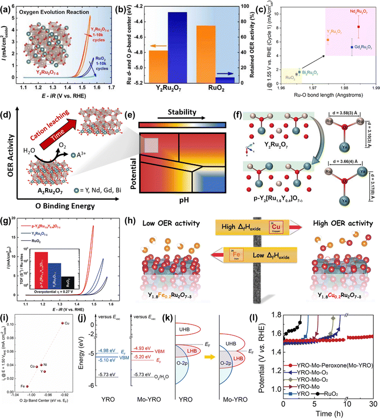 | ||
| Fig. 15 (a) OER activities of Y2Ru2O7−δ and RuO2. (b) Comparison of the overlapped band center energy of Ru 4d and O 2p orbital and retained current density at 1.50 V for Y2Ru2O7 and RuO2, respectively.154 (c) Current normalized by BET surface area for the first CV at 1.55 V vs. RHE as a function of Ru–O bond length determined from Ru K-edge EXAFS fits. (d) The relationships between OER activity and O binding energy of Ru-based pyrochlores. (e) Calculated Pourbaix diagrams of Ru-based pyrochlores.146 (f) Illustrations of crystal structures of Y2Ru2O7 and Y2[Ru1.6Y0.4]O7−δ pyrochlores, where Ru4+ is partially substituted by Y3+.155 (g) CVs and the corresponding TOFs (inset) of porous Y2[Ru1.6Y0.4]O7−δ, Y2Ru2O7−δ, and RuO2 electrocatalysts. (h) Scheme of the relationship between formation enthalpy and activity. (i) Correlation between the specific OER activity of Y1.8M0.2Ru2O7−δ estimated as current density at 1.50 V vs RHE and the O 2p band center position.157 (j) Positions of VB and EF, together with Eredox of O2/H2O at pH = 0 (left for YRO, right for Mo-YRO). (k) Schematic evolution of band alignments after modification of YRO with MoOx (LHB represents the lower Hubbard band and UHB represents the upper Hubbard band. (l) Chronopotentiometry curves for the stability tests of Mo-YRO, YRO, commercial RuO2 and other YRO-Mo related materials at 10 mA cm−2.158 | ||
To improve the catalytic performance of A2Ru2O7 pyrochlore, the substitution of A or Ru with foreign elements has been demonstrated to be an effective strategy. For instance, Kim et al. reported a Y2[Ru1.6Y0.4]O7−δ porous pyrochlore oxide with partial substitution by Y3+ on the B-site (Fig. 15f), exhibiting a higher activity compared with Y2Ru2O7−δ and RuO2 references (Fig. 15g) for acidic OER.155 The enhanced activity was due to both a high surface area and an optimized energy band structure caused by the B-site substitution. Feng and co-workers constructed an A-site substituted Y1.85Zn0.15Ru2O7−δ catalyst with a highly active and stable performance for acidic OER, which was attributed to the optimized electronic structure induced by the partial substitution of Y3+ ions with Zn2+ ions.156 Later, Kuznetsov et al. developed a group of A-site substituted Y1.8M0.2Ru2O7−δ (M = Cu, Co, Ni, Fe, Y) with controllable oxygen vacancy concentration and demonstrated that the OER activity is highly correlated to oxygen vacancy concentration.157 DFT calculations revealed that the enhanced activity along with increased oxygen vacancy concentration led to the lowered binding energy of the M–O band, which was scaling with the enthalpy of generation (ΔfHoxide) of the respective MOx species and the overlap between the M d orbitals and O 2p orbitals (Fig. 15h and i).
In addition to substitutional strategies for regulating electronic properties, the surface manipulation strategy is also proven to be an effective strategy for regulating the electronic properties of A2Ru2O7 pyrochlore. Very recently, Liu et al. implanted MoOx species on Y2Ru2O7−δ to generate Mo–O–Ru micro-interfaces with accelerated electron transfer, which resulted in rearrangement of the Ru 4d orbital alignment and elimination of the bandgap.158 In addition, the implanted MoOx could not only compress the bond length of the Ru–O band and expand the Ru–O–Ru bond angle with moderate distortion of RuO6, but could also act as an electron receiver to induce more electronegative surfaces and prevent metal ions from dissolution, hence enhancing both OER activity and stability (Fig. 15j and k). Consequently, the obtained heterogeneous catalyst delivered an improved activity with an overpotential of 240 mV at 10 mA cm−2 and enhanced stability over 30 h relative to Y2Ru2O7−δ (Fig. 15l).
As for perovskite-type ruthenates (ARuO3), a thin film of SrRuO3 OER catalyst with a very remarkable activity (1.33 V vs. RHE at 0.1 mA cm−2) under alkaline conditions has been reported (Fig. 16a).159 Nevertheless, the activity was completely degraded after only two cycles, which was due to not only the overoxidation of Ru under high voltages, but also the structure collapse of the perovskite starting at the Sr dissolution (Fig. 16a and b).159,160 To overcome the lack of superior durability of Ru-related perovskites especially in acidic electrolytes, a series of B-site mixed Sr2(RuxIr1−x)O4 were prepared and proven to display an optimal current density of 8.06 mA cm−2 at 1.55 V and good stability over 24 h at 10 mA cm−2 towards acidic OER (Fig. 16c), owing to the generation of enriched hydroxyl groups and the broadened Ru 4d band through the metal substitution.161 In the same year, Xia et al. reported a B-site mixed SrRu0.5Ir0.5O3 double perovskite with a strong electronic synergistic effect between Ir and Ru (Fig. 16d).162 When used as an acidic OER catalyst, it showed a low overpotential of 185 mV at 10 mA cm−2 and stable stability for over 50 h. In addition to B-site substitution, A site-substituted ruthenium perovskite Sr0.95Na0.05RuO3 was also found to be an enhanced acidic OER catalyst by Na+ doping in the Sr2+ position.163 Such perovskite catalysts showed an ultralow overpotential of only 120 mV at 0.5 mA cm−2 and improved structural stability (Fig. 16e), which was attributed to lower surface energy and higher dissolution potentials induced by Na-doping in the A-site (Fig. 16f). The HRTEM/digital diffraction pattern, STEM-HAADF micrographs with the line scans, and XPS results indicated that Na+ doping suppressed the dissolution of Sr and Ru and increased the structural stability, not generating the different phases, such as RuOx, during the OER. In general, metal substitutions can effectively regulate the electronic properties of perovskite-type ruthenates to greatly improve their catalytic performances. Furthermore, a quadruple perovskite oxide CaCu3Ru4O12 (Fig. 16g) was reported to deliver an ultrasmall overpotential of 171 mV at 10 mA cm−2 and much better stability compared to RuO2 for acidic OER (Fig. 16h and i), which was due to a lower Ru 4d-band center in CaCu3Ru4O12 relative to RuO2.138 These studies have indeed confirmed the role of electronic property tuning in achieving improved electrocatalytic performances and offered direction to the rational design of advanced Ru-based electrocatalysts.
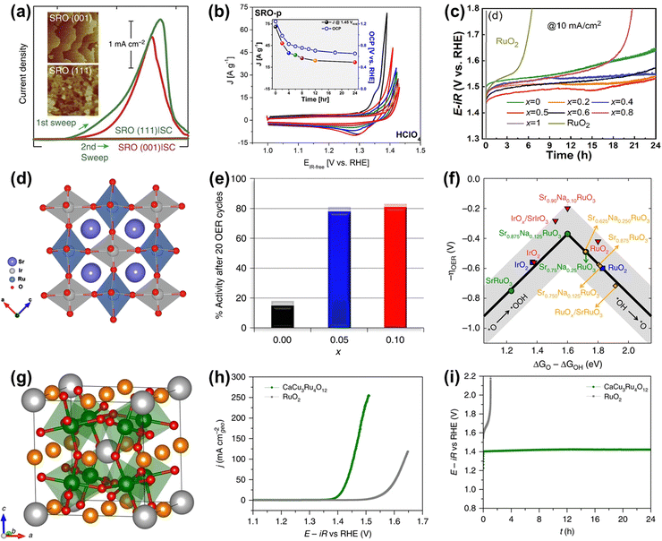 | ||
Fig. 16 (a) Current density measured (1st and 2nd sweep) at certain potentials of SRO(001) and SRO(111) side-connected with conducting paths from the top surface to the bottom substrate, denoted by SRO|SC.159 (b) Chemical stability of SRO in contact with electrolytes in HClO4.160 (c) OER stability test of the SRIO-x series and reference RuO2 electrocatalysts.161 (d) Schematic illustration of the structures of SrRu0.5Ir0.5O3.162 (e) Percentage catalytic activity of Sr1−xNaxRuO3 after 20 cycles with respect to the initial activity. (f) OER volcano-type activity plot.163 (g) Crystal structure of CaCu3Ru4O12. (h) Polarization curves of CaCu3Ru4O12 and the commercial RuO2 measured in O2-saturated 0.5![[thin space (1/6-em)]](https://www.rsc.org/images/entities/char_2009.gif) M H2SO4 solution. (i) Chronopotentiometric measurements of CaCu3Ru4O12 and the commercial RuO2 at 10 mA cm−2.138 M H2SO4 solution. (i) Chronopotentiometric measurements of CaCu3Ru4O12 and the commercial RuO2 at 10 mA cm−2.138 | ||
Apart from the three types of Ru-based catalysts (Ru-based metal, oxides, and oxometallates) mentioned above, there are some other types of Ru-based catalysts, such as Ru chalcogenides (RuTe2164) and Ru boride (RuB2165), used for acidic OER. Although their stability is far from satisfaction, these advanced works are still great breakthroughs in the expansion of Ru-based acidic OER electrocatalysts.
4. Conclusions and perspectives
All in all, the four-electron transfer OER process on the surface of Ru-related catalysts is along with the redox of Ru or O sites, in which the Ru element may dissolve under high overpotential and strong acidic conditions due to its severe overoxidation accompanied by the formation of the unstable and soluble RuO4 species. Despite these drawbacks, Ru-based materials are still proven to be promising potential candidates for PEM anodic catalysts if the stability can be greatly enhanced. To date, Ru-based materials have been extensively studied to develop highly active and stable catalysts toward acidic OER. Thereinto, the effective and universal strategy to improve stability without sacrificing activity is to reduce the bulk oxygen diffusion rate and surface exchange kinetics of Ru-based catalysts whether following any reaction mechanisms. This review provides an overview of the recent advanced progress in Ru-related acidic OER catalysts, including metallic Ru, Ru-based oxides, and oxometallate-type ruthenates, and categorically summarizes the optimizing strategy to improve both stability and activity. Of note, most of the summarized strategies are applied to regulate the electronic structure to enhance the catalytic performances of Ru-based catalysts. Despite great progress, there remains a wide gap between experimental research and practical requirements. To further promote the development of Ru-based catalysts, many issues are still needed to be studied in depth.Design of Ru-based materials
For the future development of highly active and stable Ru-related catalysts for acidic OER, heteroatom doping engineering on RuO2 may be one of the promising and effective strategies. Of note, the previous studies involving heteroatom doped RuO2 catalysts generally discuss the effect of doping engineering on electronic properties. However, the impact of structure engineering, such as specific microstructure, specific exposed facet, etc., on Ru-based oxides is rarely considered. Therefore, developing heteroatom doped RuO2 with a designed microstructure might be a resultful strategy. In addition, in view of the low reserves of Ru, atomically dispersed Ru atoms on an acid-stable non-noble metal oxide-based support (SA Ru/MO) is an ideal choice, which can not only reduce the consumption of noble metals but also construct unique geometric structures to enhance the stability of Ru-based catalysts. Nevertheless, mismatch in ionic radius, crystal structures, and electronegativity of different MOs makes the synthesis of SA Ru/MO significantly challenging. Consequently, new and effective synthetic methodologies to design advanced atomically dispersed Ru-based catalysts are needed to be explored. Furthermore, high-throughput theoretical calculations are recommended to screen advanced Ru-based catalysts for acidic OER.Evaluation of the reaction process
Theoretical studies and various descriptors have been demonstrated to be effective tools for designing advanced Ru-based catalysts toward acidic OER. Of note, current theoretical calculations are usually based on simplified models without considering practical factors to simulate the complicated actual catalysts and reaction processes, which can only afford limited information to direct the development of Ru-based catalysts. Therefore, more actual factors should be taken into consideration, such as the actual catalyst model, surface thickness, pH, external electric field, the catalyst–electrolyte interface, etc., thus uncovering a more realistic reaction process. In addition, current descriptors generally describe the bulk properties of Ru-based catalysts, being in inconformity with the viewpoint of actual reactions that occurred on the catalyst surface. Consequently, establishing a more precise descriptor should be based on the elaborate surface properties of Ru-based catalysts, and be further verified by abundant experimental evidence. More importantly, the actual active sites should be accurately identified, owing to the possible structure and/or phase reconstruction during the acidic OER process. To detailedly investigate the real active sites, some advanced in situ/operando XRD/XAS/Raman and isotope labeling techniques are needed to investigate the structural and electronic variation of Ru-based catalysts during the acidic OER process.Evaluation of PEMWE
To promote the scalable application of PEMWE, the gap between laboratory studies and the typical industrial requirement (operating over 1 A cm−2 current density for over 10 years under 80 °C) should be plugged. Satisfactorily, Wen et al. recently prepared a Ni-stabilized RuO2 (Ni-RuO2) as the anode catalyst of PEMWE, displaying >1000 h stability at 200 mA cm−2.55 Further, Shi et al. constructed a SnRuOx solid solution oxide as an anode catalyst of PEMWE, showing a remarkable performance of working for 1300 h under 1 A cm−2 at 50 °C.82 Although these designed catalysts do not meet the industrial requirement, they make the Ru-based catalysts a step closer to industrial application. More highly stable Ru-based catalysts with high activity are needed to be produced to satisfy the actual application in PEMWEs. Note that, the OER performance trends of catalysts might be different between the experimental method and industrial PEMWE. Moreover, the complex assembly process of the PEMWE cell may lead to certain deviations, which will result in some misleading information. Therefore, a standard protocol for not only evaluation (activity and stability) of anode catalysts in PEMWE under actual operating conditions but also PEMWE cell assembly should be established.Conflicts of interest
The authors declare no competing interests.Acknowledgements
We gratefully acknowledge the financial support from the Natural Science Foundation of Shandong Province of China (ZR2022QB100), Science Foundation of Qingdao University of Science and Technology (12030430010936), Taishan Scholar Program of Shandong Province, China (ts201712045) and Bk21Plus project of Korea.References
- Z. Seh, J. Kibsgaard and C. Dickens, Science, 2017, 355, eaad4998 CrossRef PubMed.
- H. Tian, A. Song, P. Zhang, K. Sun, J. Wang, B. Sun, Q. Fan, G. Shao, C. Chen, H. Liu, Y. Li and G. Wang, Adv. Mater., 2023, 35, 2210714 CrossRef CAS PubMed.
- Y. Xie, X. Chen, K. Sun, J. Zhang, W. Lai, H. Liu and G. Wang, Angew. Chem., Int. Ed., 2023, 62, e202301833 CrossRef CAS PubMed.
- L. She, G. Zhao, T. Ma, J. Chen, W. Sun and H. Pan, Adv. Funct. Mater., 2022, 32, 2108465 CrossRef CAS.
- Y. Jiao, Y. Zheng, M. Jaroniec and S. Z. Qiao, Chem. Soc. Rev., 2015, 44, 2060–2086 RSC.
- C. Li, H. Jang, S. Liu, M. G. Kim, L. Hou, X. Liu and J. Cho, Adv. Energy Mater., 2022, 12, 2200029 CrossRef CAS.
- Y. Zhang, Z. Li, L. Hou and X. Liu, Adv. Funct. Mater., 2023, 33, 2213976 CrossRef CAS.
- G. S. Ogumerem and E. N. Pistikopoulos, J. Process Contr., 2020, 91, 37–49 CrossRef CAS.
- Q. Shi, C. Zhu, D. Du and Y. Lin, Chem. Soc. Rev., 2019, 48, 3181–3192 RSC.
- R. LeRoy, Int. J. Hydrog. Energy, 1983, 8, 401–417 CrossRef CAS.
- J. Russell, L. Nuttall and A. Fickett, Am. Chem. Soc. Div. Fuel Chem. Prepr, 1973, 18, 24–40 CAS.
- M. Carmo, D. L. Fritz, J. Mergel and D. Stolten, Int. J. Hydrog. Energy, 2013, 38, 4901–4934 CrossRef CAS.
- F. Barbir, Sol. Energy, 2005, 78, 661–669 CrossRef CAS.
- S. Slade, S. Campbell, T. Ralph and F. Walsh, J. Electrochem. Soc., 2002, 149, A1556 CrossRef CAS.
- T. Reier, H. N. Nong, D. Teschner, R. Schlögl and P. Strasser, Adv. Energy Mater., 2017, 7, 1601275 CrossRef.
- L. An, C. Wei, M. Lu, H. Liu, Y. Chen, G. G. Scherer, A. C. Fisher, P. Xi, Z. J. Xu and C. H. Yan, Adv. Mater., 2021, 33, 2006328 CrossRef CAS PubMed.
- Q. Wang, Y. Cheng, H. B. Tao, Y. Liu, X. Ma, D. S. Li, H. B. Yang and B. Liu, Angew. Chem., Int. Ed., 2023, 62, e202216645 CrossRef CAS PubMed.
- N.-T. Suen, S.-F. Hung, Q. Quan, N. Zhang, Y.-J. Xu and H. M. Chen, Chem. Soc. Rev., 2017, 46, 337–365 RSC.
- Q. Qin, H. Jang, L. Chen, G. Nam, X. Liu and J. Cho, Adv. Energy Mater., 2018, 8, 1801478 CrossRef.
- L. Hou, H. Jang, H. Liu, Z. Li, M. G. Kim, Q. Qin and X. Liu, ACS Sustain. Chem. Eng., 2022, 10, 15950–15957 CrossRef CAS.
- H. Sun, X. Xu, H. Kim, W. Jung, W. Zhou and Z. Shao, Energy Environ. Mater., 2022, 0, e12441 Search PubMed.
- C. Li, H. Jang, M. G. Kim, L. Hou, X. Liu and J. Cho, Appl. Catal., B, 2022, 307, 121204 CrossRef CAS.
- G. Li, H. Jang, S. Liu, Z. Li, M. G. Kim, Q. Qin, X. Liu and J. Cho, Nat. Commun., 2022, 13, 1270 CrossRef CAS PubMed.
- F.-Y. Chen, Z.-Y. Wu, Z. Adler and H. Wang, Joule, 2021, 5, 1704–1731 CrossRef CAS.
- Y. Wang, Z. Li, L. Hou, Y. Wang, L. Zhang, T. Wang, H. Liu, S. Liu, Q. Qin and X. Liu, ACS Appl. Mater. Interfaces, 2023, 15, 14282–14290 CAS.
- H. Sun and W. Jung, J. Mater. Chem. A, 2021, 9, 15506–15521 RSC.
- Q. Qin, H. Jang, Y. Wang, L. Zhang, Z. Li, M. G. Kim, S. Liu, X. Liu and J. Cho, Adv. Energy Mater., 2021, 11, 2003561 CrossRef CAS.
- L. Li, X. Cao, J. Huo, J. Qu, W. Chen, C. Liu, Y. Zhao, H. Liu and G. Wang, J. Energy Chem., 2023, 76, 195–213 CrossRef CAS.
- A. M. Patel, J. K. Nørskov, K. A. Persson and J. H. Montoya, Phys. Chem. Chem. Phys., 2019, 21, 25323–25327 RSC.
- Z. Chen, L. Guo, L. Pan, T. Yan, Z. He, Y. Li, C. Shi, Z. F. Huang, X. Zhang and J. J. Zou, Adv. Energy Mater., 2022, 12, 2103670 CrossRef CAS.
- L. Fu, F. Yang, G. Cheng and W. Luo, Nanoscale, 2018, 10, 1892–1897 RSC.
- Z. Fan, Y. Ji, Q. Shao, S. Geng, W. Zhu, Y. Liu, F. Liao, Z. Hu, Y.-C. Chang and C.-W. Pao, Joule, 2021, 5, 3221–3234 CrossRef CAS.
- L. Yang, L. Shi, H. Chen, X. Liang, B. Tian, K. Zhang, Y. Zou and X. Zou, Adv. Mater., 2022, 2208539 Search PubMed.
- F. Liao, K. Yin, Y. Ji, W. Zhu, Z. Fan, Y. Li, J. Zhong, M. Shao, Z. Kang and Q. Shao, Nat. Commun., 2023, 14, 1248 CrossRef CAS PubMed.
- P. C. Vesborg and T. F. Jaramillo, RSC Adv., 2012, 2, 7933–7947 RSC.
- A. Hauch, R. Küngas, P. Blennow, A. B. Hansen, J. B. Hansen, B. V. Mathiesen and M. B. Mogensen, Science, 2020, 370, eaba6118 CrossRef CAS PubMed.
- R. M. Bullock, J. G. Chen, L. Gagliardi, P. J. Chirik, O. K. Farha, C. H. Hendon, C. W. Jones, J. A. Keith, J. Klosin and S. D. Minteer, Science, 2020, 369, eabc3183 CrossRef CAS PubMed.
- J. Ying, J.-B. Chen, Y.-X. Xiao, S. I. C. de Torresi, K. I. Ozoemena and X.-Y. Yang, J. Mater. Chem. A, 2023, 11, 1634–1650 RSC.
- X. Cao, J. Huo, L. Li, J. Qu, Y. Zhao, W. Chen, C. Liu, H. Liu and G. Wang, Adv. Energy Mater., 2022, 12, 2202119 CrossRef CAS.
- J. Shan, Y. Zheng, B. Shi, K. Davey and S.-Z. Qiao, ACS Energy Lett., 2019, 4, 2719–2730 CrossRef CAS.
- M. Zhao, Z. Chen, Z. Lyu, Z. D. Hood, M. Xie, M. Vara, M. Chi and Y. Xia, J. Am. Chem. Soc., 2019, 141, 7028–7036 CrossRef CAS PubMed.
- J. Shan, T. Ling, K. Davey, Y. Zheng and S. Z. Qiao, Adv. Mater., 2019, 31, 1900510 CrossRef PubMed.
- Q. Zhang, K. Kusada, D. Wu, N. Ogiwara, T. Yamamoto, T. Toriyama, S. Matsumura, S. Kawaguchi, Y. Kubota and T. Honma, Chem. Sci., 2019, 10, 5133–5137 RSC.
- Y. Yao, S. Hu, W. Chen, Z.-Q. Huang, W. Wei, T. Yao, R. Liu, K. Zang, X. Wang and G. Wu, Nat. Catal., 2019, 2, 304–313 CrossRef CAS.
- Y. Qin, T. Yu, S. Deng, X.-Y. Zhou, D. Lin, Q. Zhang, Z. Jin, D. Zhang, Y.-B. He and H.-J. Qiu, Nat. Commun., 2022, 13, 3784 CrossRef CAS PubMed.
- J. Yu, Q. He, G. Yang, W. Zhou, Z. Shao and M. Ni, ACS Catal., 2019, 9, 9973–10011 CrossRef CAS.
- R. Walker, M. Bailes and L. Peter, Electrochim. Acta, 1998, 44, 1289–1294 CrossRef CAS.
- A. Izgorodin, O. Winther-Jensen and D. R. MacFarlane, Aust. J. Chem., 2012, 65, 638–642 CrossRef CAS.
- L. Zhang, H. Jang, H. Liu, M. G. Kim, D. Yang, S. Liu, X. Liu and J. Cho, Angew. Chem., Int. Ed., 2021, 133, 18969–18977 CrossRef.
- C.-J. Chang, Y.-C. Chu, H.-Y. Yan, Y.-F. Liao and H. M. Chen, Dalton Trans., 2019, 48, 7122–7129 RSC.
- H. Jin, X. Liu, P. An, C. Tang, H. Yu, Q. Zhang, H.-J. Peng, L. Gu, Y. Zheng and T. Song, Nat. Commun., 2023, 14, 354 CrossRef CAS PubMed.
- H. Liu, Z. Zhang, J. Fang, M. Li, M. G. Sendeku, X. Wang, H. Wu, Y. Li, J. Ge and Z. Zhuang, Joule, 2023, 7, 558–573 CrossRef CAS.
- Y. Wen, C. Liu, R. Huang, H. Zhang, X. Li, F. P. García de Arquer, Z. Liu, Y. Li and B. Zhang, Nat. Commun., 2022, 13, 4871 CrossRef CAS PubMed.
- N. Yao, H. Jia, J. Zhu, Z. Shi, H. Cong, J. Ge and W. Luo, Chem, 2023, 9, 1–15 Search PubMed.
- Z.-Y. Wu, F.-Y. Chen, B. Li, S.-W. Yu, Y. Z. Finfrock, D. M. Meira, Q.-Q. Yan, P. Zhu, M.-X. Chen and T.-W. Song, Nat. Mater., 2023, 22, 100–108 CrossRef CAS PubMed.
- Y. Wang, R. Yang, Y. Ding, B. Zhang, H. Li, B. Bai, M. Li, Y. Cui, J. Xiao and Z.-S. Wu, Nat. Commun., 2023, 14, 1412 CrossRef CAS PubMed.
- R. R. Rao, M. J. Kolb, L. Giordano, A. F. Pedersen, Y. Katayama, J. Hwang, A. Mehta, H. You, J. R. Lunger and H. Zhou, Nat. Catal., 2020, 3, 516–525 CrossRef CAS.
- K. A. Stoerzinger, O. Diaz-Morales, M. Kolb, R. R. Rao, R. Frydendal, L. Qiao, X. R. Wang, N. B. Halck, J. Rossmeisl and H. A. Hansen, ACS Energy Lett., 2017, 2, 876–881 CrossRef CAS.
- X. Peng, S. Zhao, Y. Mi, L. Han, X. Liu, D. Qi, J. Sun, Y. Liu, H. Bao and L. Zhuo, Small, 2020, 16, 2002888 CrossRef CAS PubMed.
- L. Qiu, G. Zheng, Y. He, L. Lei and X. Zhang, Chem. Eng. J., 2021, 409, 128155 CrossRef CAS.
- J. Rossmeisl, Z.-W. Qu, H. Zhu, G.-J. Kroes and J. K. Nørskov, J. Electroanal. Chem., 2007, 607, 83–89 CrossRef CAS.
- I. C. Man, H. Y. Su, F. Calle-Vallejo, H. A. Hansen, J. I. Martínez, N. G. Inoglu, J. Kitchin, T. F. Jaramillo, J. K. Nørskov and J. Rossmeisl, ChemCatChem, 2011, 3, 1159–1165 CrossRef CAS.
- E. A. Paoli, F. Masini, R. Frydendal, D. Deiana, C. Schlaup, M. Malizia, T. W. Hansen, S. Horch, I. E. Stephens and I. Chorkendorff, Chem. Sci., 2015, 6, 190–196 RSC.
- J. Lee, A. Kumar, T. Yang, X. Liu, A. R. Jadhav, G. H. Park, Y. Hwang, J. Yu, C. T. Nguyen and Y. Liu, Energy Environ. Sci., 2020, 13, 5152–5164 RSC.
- N. B. Halck, V. Petrykin, P. Krtil and J. Rossmeisl, Phys. Chem. Chem. Phys., 2014, 16, 13682–13688 RSC.
- Y.-H. Fang and Z.-P. Liu, J. Am. Chem. Soc., 2010, 132, 18214–18222 CrossRef CAS PubMed.
- D. Chen, Y.-H. Fang and Z.-P. Liu, Phys. Chem. Chem. Phys., 2012, 14, 16612–16617 RSC.
- C. Wei, Z. Feng, G. G. Scherer, J. Barber, Y. Shao-Horn and Z. J. Xu, Adv. Mater., 2017, 29, 1606800 CrossRef PubMed.
- M. J. Craig and M. Garcia-Melchor, Curr. Opin. Electrochem., 2022, 101044 CrossRef CAS.
- X. Cheng, E. Fabbri, Y. Yamashita, I. E. Castelli, B. Kim, M. Uchida, R. Haumont, I. Puente-Orench and T. J. Schmidt, ACS Catal., 2018, 8, 9567–9578 CrossRef CAS.
- J. K. Nørskov, F. Abild-Pedersen, F. Studt and T. Bligaard, Proc. Natl. Acad. Sci. U. S. A., 2011, 108, 937–943 CrossRef PubMed.
- Z.-J. Zhao, S. Liu, S. Zha, D. Cheng, F. Studt, G. Henkelman and J. Gong, Nat. Rev. Mater., 2019, 4, 792–804 CrossRef.
- J. Li, Nanomicro Lett., 2022, 14, 112 CAS.
- Y. Hu, D. Huang, J. Zhang, Y. Huang, M. S. J. T. Balogun and Y. Tong, ChemCatChem, 2019, 11, 6051–6060 CrossRef CAS.
- D. Luo, B. Yang, Z. Mei, Q. Kang, G. Chen, X. Liu and N. Zhang, ACS Appl. Mater. Interfaces, 2022, 14, 52857–52867 CrossRef CAS PubMed.
- K. Yang, P. Xu, Z. Lin, Y. Yang, P. Jiang, C. Wang, S. Liu, S. Gong, L. Hu and Q. Chen, Small, 2018, 14, 1803009 CrossRef PubMed.
- W. T. Hong, M. Risch, K. A. Stoerzinger, A. Grimaud, J. Suntivich and Y. Shao-Horn, Energy Environ. Sci., 2015, 8, 1404–1427 RSC.
- S. Liu, Y. Chang, N. He, S. Zhu, L. Wang and X. Liu, ACS Appl. Mater. Interfaces, 2023, 15, 20563–20570 CrossRef CAS PubMed.
- Y. Matsumoto, H. Yoneyama and H. Tamura, J. Electroanal. Chem. Interfacial Electrochem., 1977, 79, 319–326 CrossRef CAS.
- J. Hwang, R. R. Rao, L. Giordano, Y. Katayama, Y. Yu and Y. Shao-Horn, Science, 2017, 358, 751–756 CrossRef CAS PubMed.
- H. B. Tao, L. Fang, J. Chen, H. B. Yang, J. Gao, J. Miao, S. Chen and B. Liu, J. Am. Chem. Soc., 2016, 138, 9978–9985 CrossRef CAS PubMed.
- Z. Shi, J. Li, Y. Wang, S. Liu, J. Zhu, J. Yang, X. Wang, J. Ni, Z. Jiang and L. Zhang, Nat. Commun., 2023, 14, 843 CrossRef CAS PubMed.
- T. Reier, M. Oezaslan, P. Strasser and A. Catal, P. Grote, A. Savan, BR Shrestha, S. Merzlikin, B. Breitbach, A. Ludwig, Catal. Today, 2016, 262, 170–180 Search PubMed.
- E. Paoli, F. Masini, R. Frydendal, D. Deiana, C. Schlaup, M. Malizia, T. Hansen, S. Horch, I. Stephens and I. Chorkendorff, Chem. Sci., 2015, 6, 190–196 RSC.
- R. Kötz, H. Lewerenz and S. Stucki, J. Electrochem. Soc., 1983, 130, 825 CrossRef.
- R. Kötz, S. Stucki, D. Scherson and D. Kolb, J. Electroanal. Chem. Interfacial Electrochem., 1984, 172, 211–219 CrossRef.
- K. Klyukin, A. Zagalskaya and V. Alexandrov, J. Phys. Chem. C, 2019, 123, 22151–22157 CrossRef CAS.
- S. Cherevko, Curr. Opin. Electrochem., 2018, 8, 118–125 CrossRef CAS.
- S. Cherevko, A. R. Zeradjanin, A. A. Topalov, N. Kulyk, I. Katsounaros and K. J. Mayrhofer, ChemCatChem, 2014, 6, 2219–2223 CrossRef CAS.
- J. S. Yoo, X. Rong, Y. Liu and A. M. Kolpak, ACS Catal., 2018, 8, 4628–4636 CrossRef CAS.
- A. Grimaud, O. Diaz-Morales, B. Han, W. T. Hong, Y.-L. Lee, L. Giordano, K. A. Stoerzinger, M. T. Koper and Y. Shao-Horn, Nat. Chem., 2017, 9, 457–465 CrossRef CAS PubMed.
- X. Wang, H. Zhong, S. Xi, W. S. V. Lee and J. Xue, Adv. Mater., 2022, 34, 2107956 CrossRef CAS PubMed.
- T. Bligaard, J. K. Nørskov, S. Dahl, J. Matthiesen, C. H. Christensen and J. Sehested, J. Catal., 2004, 224, 206–217 CrossRef CAS.
- P. Adiga, W. Nunn, C. Wong, A. K. Manjeshwar, S. Nair, B. Jalan and K. A. Stoerzinger, Mater. Today Energy, 2022, 28, 101087 CrossRef CAS.
- S. Geiger, O. Kasian, M. Ledendecker, E. Pizzutilo, A. M. Mingers, W. T. Fu, O. Diaz-Morales, Z. Li, T. Oellers and L. Fruchter, Nat. Catal., 2018, 1, 508–515 CrossRef CAS.
- C. Roy, R. R. Rao, K. A. Stoerzinger, J. Hwang, J. Rossmeisl, I. Chorkendorff, Y. Shao-Horn and I. E. Stephens, ACS Energy Lett., 2018, 3, 2045–2051 CrossRef CAS.
- Y. Tian, S. Wang, E. Velasco, Y. Yang, L. Cao, L. Zhang, X. Li, Y. Lin, Q. Zhang and L. Chen, iScience, 2020, 23, 100756 CrossRef CAS PubMed.
- M. T. Koper, Chem. Sci., 2013, 4, 2710–2723 RSC.
- C. Lin, J.-L. Li, X. Li, S. Yang, W. Luo, Y. Zhang, S.-H. Kim, D.-H. Kim, S. S. Shinde and Y.-F. Li, Nat. Catal., 2021, 4, 1012–1023 CrossRef CAS.
- A. R. Poerwoprajitno, L. Gloag, T. M. Benedetti, S. Cheong, J. Watt, D. L. Huber, J. J. Gooding and R. D. Tilley, Small, 2019, 15, 1804577 CrossRef PubMed.
- Z. Xia and S. Guo, Chem. Soc. Rev., 2019, 48, 3265–3278 RSC.
- X. Yang, Y. Wang, X. Tong and N. Yang, Adv. Energy Mater., 2022, 12, 2102261 CrossRef CAS.
- J.-Q. Wang, C. Xi, M. Wang, L. Shang, J. Mao, C.-K. Dong, H. Liu, S. A. Kulinich and X.-W. Du, ACS Catal., 2020, 10, 12575–12581 CrossRef CAS.
- R. Forgie, G. Bugosh, K. Neyerlin, Z. Liu and P. Strasser, Electrochem. Solid-State Lett., 2010, 13, B36 CrossRef CAS.
- N. Danilovic, R. Subbaraman, K. C. Chang, S. H. Chang, Y. Kang, J. Snyder, A. P. Paulikas, D. Strmcnik, Y. T. Kim and D. Myers, Angew. Chem., Int. Ed., 2014, 53, 14016–14021 CrossRef CAS PubMed.
- Y. Jiang, Y. Mao, Y. Jiang, H. Liu, W. Shen, M. Li and R. He, Chem. Eng. J., 2022, 450, 137909 CrossRef CAS.
- L. An, F. Yang, C. Fu, X. Cai, S. Shen, G. Xia, J. Li, Y. Du, L. Luo and J. Zhang, Adv. Funct. Mater., 2022, 32, 2200131 CrossRef CAS.
- Q. Yao, B. Huang, N. Zhang, M. Sun, Q. Shao and X. Huang, Angew. Chem., Int. Ed., 2019, 131, 14121–14126 CrossRef.
- L. Li, L. Bu, B. Huang, P. Wang, C. Shen, S. Bai, T. S. Chan, Q. Shao, Z. Hu and X. Huang, Adv. Mater., 2021, 33, 2105308 CrossRef CAS PubMed.
- J. Xu, J. Li, Z. Lian, A. Araujo, Y. Li, B. Wei, Z. Yu, O. Bondarchuk, I. Amorim and V. Tileli, ACS Catal., 2021, 11, 3402–3413 CrossRef CAS.
- T. Zhu, S. Liu, B. Huang, Q. Shao, M. Wang, F. Li, X. Tan, Y. Pi, S.-C. Weng and B. Huang, Energy Environ. Sci., 2021, 14, 3194–3202 RSC.
- J. Zhu, Y. Guo, F. Liu, H. Xu, L. Gong, W. Shi, D. Chen, P. Wang, Y. Yang and C. Zhang, Angew. Chem., Int. Ed., 2021, 133, 12436–12442 CrossRef.
- J. Shan, C. Guo, Y. Zhu, S. Chen, L. Song, M. Jaroniec, Y. Zheng and S.-Z. Qiao, Chem, 2019, 5, 445–459 CAS.
- D. Chen, R. Yu, D. Wu, H. Zhao, P. Wang, J. Zhu, P. Ji, Z. Pu, L. Chen and J. Yu, Nano Energy, 2022, 100, 107445 CrossRef CAS.
- X.-F. Yang, A. Wang, B. Qiao, J. Li, J. Liu and T. Zhang, Acc. Chem. Res., 2013, 46, 1740–1748 CrossRef CAS PubMed.
- R. Lang, X. Du, Y. Huang, X. Jiang, Q. Zhang, Y. Guo, K. Liu, B. Qiao, A. Wang and T. Zhang, Chem. Rev., 2020, 120, 11986–12043 CrossRef CAS PubMed.
- Y. Chen, S. Ji, C. Chen, Q. Peng, D. Wang and Y. Li, Joule, 2018, 2, 1242–1264 CrossRef CAS.
- L. Cao, Q. Luo, J. Chen, L. Wang, Y. Lin, H. Wang, X. Liu, X. Shen, W. Zhang and W. Liu, Nat. Commun., 2019, 10, 4849 CrossRef PubMed.
- C. Rong, X. Shen, Y. Wang, L. Thomsen, T. Zhao, Y. Li, X. Lu, R. Amal and C. Zhao, Adv. Mater., 2022, 34, 2110103 CrossRef CAS PubMed.
- Z. Wang, Y.-R. Zheng, I. Chorkendorff and J. K. Nørskov, ACS Energy Lett., 2020, 5, 2905–2908 CrossRef CAS.
- A. Li, H. Ooka, N. Bonnet, T. Hayashi, Y. Sun, Q. Jiang, C. Li, H. Han and R. Nakamura, Angew. Chem., Int. Ed., 2019, 131, 5108–5112 CrossRef.
- Z. L. Zhao, Q. Wang, X. Huang, Q. Feng, S. Gu, Z. Zhang, H. Xu, L. Zeng, M. Gu and H. Li, Energy Environ. Sci., 2020, 13, 5143–5151 RSC.
- R. Ge, L. Li, J. Su, Y. Lin, Z. Tian and L. Chen, Adv. Energy Mater., 2019, 9, 1901313 CrossRef.
- S. C. Sun, H. Jiang, Z. Y. Chen, Q. Chen, M. Y. Ma, L. Zhen, B. Song and C. Y. Xu, Angew. Chem., Int. Ed., 2022, 134, e202202519 Search PubMed.
- Y. Li, W. Wang, M. Cheng, Y. Feng, X. Han, Q. Qian, Y. Zhu and G. Zhang, Adv. Mater., 2023, 2206351 CrossRef CAS PubMed.
- X. Cui, P. Ren, C. Ma, J. Zhao, R. Chen, S. Chen, N. P. Rajan, H. Li, L. Yu and Z. Tian, Adv. Mater., 2020, 32, 1908126 CrossRef CAS PubMed.
- X. Wang, X. Wan, X. Qin, C. Chen, X. Qian, Y. Guo, Q. Xu, W.-B. Cai, H. Yang and K. Jiang, ACS Catal., 2022, 12, 9437–9445 CrossRef CAS.
- S. Niu, X.-P. Kong, S. Li, Y. Zhang, J. Wu, W. Zhao and P. Xu, Appl. Catal., B, 2021, 297, 120442 CrossRef CAS.
- T. Kwon, H. Yang, M. Jun, T. Kim, J. Joo, J. Kim, H. Baik, J. Y. Kim and K. Lee, J. Mater. Chem. A, 2021, 9, 14352–14362 RSC.
- J. F. Godinez-Salomon, F. Ospina-Acevedo, L. A. Albiter, K. O. Bailey, Z. G. Naymik, R. Mendoza-Cruz, P. B. Balbuena and C. P. Rhodes, ACS Appl. Nano Mater., 2022, 5, 11752–11775 CrossRef CAS.
- Y. Lin, Z. Tian, L. Zhang, J. Ma, Z. Jiang, B. J. Deibert, R. Ge and L. Chen, Nat. Commun., 2019, 10, 162 CrossRef PubMed.
- K. Wang, Y. Wang, B. Yang, Z. Li, X. Qin, Q. Zhang, L. Lei, M. Qiu, G. Wu and Y. Hou, Energy Environ. Sci., 2022, 15, 2356–2365 RSC.
- Y. Xue, J. Fang, X. Wang, Z. Xu, Y. Zhang, Q. Lv, M. Liu, W. Zhu and Z. Zhuang, Adv. Funct. Mater., 2021, 31, 2101405 CrossRef CAS.
- K. Shah, R. Dai, M. Mateen, Z. Hassan, Z. Zhuang, C. Liu, M. Israr, W. C. Cheong, B. Hu and R. Tu, Angew. Chem., Int. Ed., 2022, 134, e202114951 CrossRef.
- J. Su, R. Ge, K. Jiang, Y. Dong, F. Hao, Z. Tian, G. Chen and L. Chen, Adv. Mater., 2018, 30, 1801351 CrossRef PubMed.
- L. Hou, Z. Li, H. Jang, Y. Wang, X. Cui, X. Gu, M. G. Kim, L. Feng, S. Liu and X. Liu, Adv. Energy Mater., 2023, 2300177 CrossRef CAS.
- Z. Li, S. Wang, Y. Tian, B. Li, H. Jun Yan, S. Zhang, Z. Liu, Q. Zhang, Y. Lin and L. Chen, Chem. Commun., 2020, 56, 1749–1752 RSC.
- X. Miao, L. Zhang, L. Wu, Z. Hu, L. Shi and S. Zhou, Nat. Commun., 2019, 10, 3809 CrossRef PubMed.
- Y. Wen, P. Chen, L. Wang, S. Li, Z. Wang, J. Abed, X. Mao, Y. Min, C. T. Dinh and P. D. Luna, J. Am. Chem. Soc., 2021, 143, 6482–6490 CrossRef CAS PubMed.
- H. Jin, S. Choi, G. J. Bang, T. Kwon, H. S. Kim, S. J. Lee, Y. Hong, D. W. Lee, H. S. Park and H. Baik, Energy Environ. Sci., 2022, 15, 1119–1130 RSC.
- J. He, X. Zhou, P. Xu and J. Sun, Adv. Energy Mater., 2021, 11, 2102883 CrossRef CAS.
- R. Huang, Y. Wen, H. Peng and B. Zhang, Chin. J. Catal., 2022, 43, 130–138 CrossRef CAS.
- Y. Wu, R. Yao, Q. Zhao, J. Li and G. Liu, Chem. Eng. J., 2022, 439, 135699 CrossRef CAS.
- J. He, W. Li, P. Xu and J. Sun, Appl. Catal., B, 2021, 298, 120528 CrossRef CAS.
- N. Han, S. Feng, Y. Liang, J. Wang, W. Zhang, X. Guo, Q. Ma, Q. Liu, W. Guo and Z. Zhou, Adv. Funct. Mater., 2023, 2208399 CrossRef CAS.
- M. A. Hubert, A. M. Patel, A. Gallo, Y. Liu, E. Valle, M. Ben-Naim, J. Sanchez, D. Sokaras, R. Sinclair and J. K. Nørskov, ACS Catal., 2020, 10, 12182–12196 CrossRef CAS.
- J. He, W. Chen, H. Gao, Y. Chen, L. Zhou, Y. Zou, R. Chen, L. Tao, X. Lu and S. Wang, Chem. Catal., 2022, 2, 578–594 CrossRef CAS.
- J. Wang, C. Cheng, Q. Yuan, H. Yang, F. Meng, Q. Zhang, L. Gu, J. Cao, L. Li and S.-C. Haw, Chem, 2022, 8, 1673–1687 CAS.
- C. Liu, B. Sheng, Q. Zhou, D. Cao, H. Ding, S. Chen, P. Zhang, Y. Xia, X. Wu and L. Song, Nano Res., 2022, 15, 7008–7015 CrossRef CAS.
- Q. Yao, Z. Yu, Y.-H. Chu, Y.-H. Lai, T.-S. Chan, Y. Xu, Q. Shao and X. Huang, Nano Res., 2022, 15, 3964–3970 CrossRef CAS.
- K. Huang, C. Lin, G. Yu, P. Du, X. Xie, X. He, Z. Zheng, N. Sun, H. Tang and X. Li, Adv. Funct. Mater., 2023, 33, 2211102 CrossRef CAS.
- C. Liu, Y. Jiang, T. Wang, Q. Li and Y. Liu, Adv. Sci., 2023, 10, 2207429 CrossRef CAS PubMed.
- J. Wang, H. Yang, F. Li, L. Li, J. Wu, S. Liu, T. Cheng, Y. Xu, Q. Shao and X. Huang, Sci. Adv., 2022, 8, eabl9271 CrossRef CAS PubMed.
- J. Kim, P.-C. Shih, K.-C. Tsao, Y.-T. Pan, X. Yin, C.-J. Sun and H. Yang, J. Am. Chem. Soc., 2017, 139, 12076–12083 CrossRef CAS PubMed.
- J. Kim, P. C. Shih, Y. Qin, Z. Al-Bardan, C. J. Sun and H. Yang, Angew. Chem., Int. Ed., 2018, 130, 14073–14077 CrossRef.
- Q. Feng, Q. Wang, Z. Zhang, Y. Xiong, H. Li, Y. Yao, X.-Z. Yuan, M. C. Williams, M. Gu and H. Chen, Appl. Catal., B, 2019, 244, 494–501 CrossRef CAS.
- D. A. Kuznetsov, M. A. Naeem, P. V. Kumar, P. M. Abdala, A. Fedorov and C. R. Müller, J. Am. Chem. Soc., 2020, 142, 7883–7888 CrossRef CAS PubMed.
- T. Liu, H. Guo, Y. Chen, Z. Zhang and F. Wang, Small, 2023, 2206698 CrossRef CAS PubMed.
- S. H. Chang, N. Danilovic, K.-C. Chang, R. Subbaraman, A. P. Paulikas, D. D. Fong, M. J. Highland, P. M. Baldo, V. R. Stamenkovic and J. W. Freeland, Nat. Commun., 2014, 5, 4191 CrossRef CAS PubMed.
- B.-J. Kim, D. F. Abbott, X. Cheng, E. Fabbri, M. Nachtegaal, F. Bozza, I. E. Castelli, D. Lebedev, R. Schäublin and C. Coperet, ACS Catal., 2017, 7, 3245–3256 CrossRef CAS.
- F. Wang, C. Zhang and H. Yang, J. Energy Chem., 2022, 70, 623–629 CrossRef CAS.
- T. Xia, C. Liu, Y. Lu, W. Jiang, H. Li, Y. Ma, Y. Wu and G. Che, Appl. Surf. Sci., 2022, 605, 154727 CrossRef CAS.
- M. Retuerto, L. Pascual, F. Calle-Vallejo, P. Ferrer, D. Gianolio, A. G. Pereira, Á. García, J. Torrero, M. T. Fernández-Díaz and P. Bencok, Nat. Commun., 2019, 10, 2041 CrossRef PubMed.
- J. Wang, L. Han, B. Huang, Q. Shao, H. L. Xin and X. Huang, Nat. Commun., 2019, 10, 5692 CrossRef CAS PubMed.
- D. Chen, T. Liu, P. Wang, J. Zhao, C. Zhang, R. Cheng, W. Li, P. Ji, Z. Pu and S. Mu, ACS Energy Lett., 2020, 5, 2909–2915 CrossRef CAS.
| This journal is © The Royal Society of Chemistry 2023 |


