 Open Access Article
Room-temperature ferroelectric and ferroelastic orders coexisting in a new tetrafluoroborate-based perovskite†
Xiao-Xian
Chen
a,
Xiao-Yue
Zhang
 b,
De-Xuan
Liu
a,
Rui-Kang
Huang
a,
Sha-Sha
Wang
a,
Li-Qun
Xiong
b,
Wei-Xiong
Zhang
b,
De-Xuan
Liu
a,
Rui-Kang
Huang
a,
Sha-Sha
Wang
a,
Li-Qun
Xiong
b,
Wei-Xiong
Zhang
 *a and
Xiao-Ming
Chen
a
aMOE Key Laboratory of Bioinorganic and Synthetic Chemistry, School of Chemistry, Sun Yat-Sen University, Guangzhou 510275, China. E-mail: zhangwx6@mail.sysu.edu.cn
bState Key Laboratory of Optoelectronic Materials and Technologies, School of Physics, Sun Yat-Sen University, Guangzhou 510275, China
First published on 17th May 2021
Abstract
The coexistence of multiferroic orders has attracted increasing attention for its potential applications in multiple-state memory, switches, and computing, but it is still challenging to design single-phase crystalline materials hosting multiferroic orders at above room temperature. By utilizing versatile ABX3-type perovskites as a structural model, we judiciously introduced a polar organic cation with easily changeable conformations into a tetrafluoroborate-based perovskite system, and successfully obtained an unprecedented molecular perovskite, (homopiperazine-1,4-diium)[K(BF4)3], hosting both ferroelectricity and ferroelasticity at above room temperature. By using the combined techniques of variable-temperature single-crystal X-ray structural analyses, differential scanning calorimetry, and dielectric, second harmonic generation, and piezoresponse force microscopy measurements, we demonstrated the domain structures for ferroelectric and ferroelastic orders, and furthermore disclosed how the delicate interplay between stepwise changed dynamics of organic cations and cooperative deformation of the inorganic framework induces ferroelectric and ferroelastic phase transitions at 311 K and 455 K, respectively. This instance, together with the underlying mechanism of ferroic transitions, provides important clues for designing advanced multiferroic materials based on organic–inorganic hybrid crystals.
Introduction
Multiferroics, in which two or more ferroic orders (including electric, elastic, and magnetic ones) coexist, have attracted much attention due to their potential applications in multiple-state memory, switches, and computing. Parallel to intensive studies on inorganic multiferroics,1–3 the exploration of multiferroic materials has been extended to organic–inorganic hybrid materials, as they may serve as a supplement to inorganic ones in next generation flexible devices, benefiting from their mechanical flexibility, mild synthesis, and easy processing to thin films.4–10 In particular, ABX3-type molecular perovskites, in which each site can hold diverse components, are regarded as an important host–guest structural model for searching for molecule-based multiferroic materials.11–17 For example, some metal formate perovskites, (Me2NH2)[M(HCOO)3] (M = MnII, FeII, CoII, NiII),18 reveal magnetic and electric orders at below 36 K. Two ferroelastic perovskites, (Et3P(CH2)2F/Et3P(CH2)2Cl)–[Mn(N(CN)2)3],19 display antiferromagnetic orders at below 2.4 K. An azido perovskite, (Me4N)[Mn(N3)3],20,21 was suggested as a multiferroic material with the coexistence of antiferroelectricity, ferroelasticity, and magnetic bistabilities at room temperature. Nevertheless, multiferroic materials with the coexistence of ferroelectric and ferroelastic orders, especially those occurring at above room temperature, are very scarce. Very recently, Wang et al. demonstrated interesting coupled ferroelasticity and ferroelectricity in a hexagonal perovskite system,22 in which a ferroelastic switch with a large shear strain of up to 21.5% could be driven by an electric field and yield a recorded piezoelectric coefficient d35 of up to 4800 pm V−1.In the past decade, much effort was devoted to constructing molecular perovskites for wide usage, by utilizing multi-atomic X-bridging ligands, such as cyano, azido, thiocyanate, nitrate, and dicyanamide.23–29 For instance, by employing the tetrahedral perchlorate ion (ClO4−), we recently constructed a large family of molecular perovskites for use as promising practical high-energy materials.30–32 Similarly, as another well-known tetrahedral ion, tetrafluoroborate (BF4−) attracts increasing attention with an expectation to serve as a bridging ligand for constructing molecular perovskites. Since the first tetrafluoroborate-based perovskite, (H2dabco)(NH4)(BF4)3 (H2dabco2+ = 1,4-diazabicyclo[2.2.2]octane-1,4-diium), was reported by Liu et al. in 2011,33 efforts to date have led to five instances.34–37 In detail, replacing the NH4+ cation with alkali ions yielded three analogues, (H2dabco)[M′(BF4)3] (M′ = Na+, K+, Rb+), which undergo reversible phase transitions at 403, 410, and 333 K, respectively, accompanied by step-like dielectric switches34,36,37 and considerable latent heats for potential heat storage. Recently, changing the A-site cations yielded two analogues, (H2pz)[Na(BF4)3] (H2pz2+ = piperazine-1,4-diium)34 and (H2mdabco)(NH4)(BF4)3 (H2mdabco2+ = 1-methyl-1,4-diazabicyclo-[2.2.2]octane-1,4-diium),35 which were found to undergo phase transitions at 405 K and 368 K, respectively. However, only (H2pz)[Na(BF4)3] was reported to crystallize in a polar space group (P43) at room temperature but its high-temperature phase is unknown; all the other known phases in these six instances are centrosymmetric structures, and no ferroelectric or ferroelastic phase has been identified in these tetrafluoroborate-based perovskites.
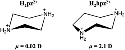
Aiming to establish ferroic order for tetrafluoroborate-based perovskites, we judiciously chose a polar cation, homopiperazine-1,4-diium (H2hpz2+), to assemble with alkali ions and the tetrafluoroborate ion. Compared with the H2pz2+ cation, the H2hpz2+ cation with an additional –CH2– group possesses a relatively larger dipole moment of ca. 2.1 D (Scheme 1), and moreover, has a more flexible configuration to break the mirror symmetry thus facilitating the establishment of a reversible polarization.
Our efforts successfully yielded an unprecedented tetrafluoroborate-based multiferroic crystal, (H2hpz)[K(BF4)3] (1), revealing both ferroelectric and ferroelastic orders at above room temperature. Herein, we disclose how the delicate interplay between the stepwise changed molecular dynamics of the organic cation and the synergistic deformation of inorganic framework essentially induces three-step phase transitions and the ferroic orders in 1, by using the combined techniques of variable-temperature single-crystal X-ray structural analyses, differential scanning calorimetry (DSC), and dielectric, second harmonic generation (SHG) effect, and piezoresponse force microscopy (PFM) measurements.
Experimental section
Materials and instrumentations
All chemicals were commercially available and used without further purification. Powder X-ray diffraction (PXRD) patterns were recorded using a Bruker D8 ADVANCE X-ray powder diffractometer (Cu Kα, λ = 1.54184 Å). Thermogravimetric analysis was performed using a STA 449 F3 Jupiter system with a heating rate of 10 K min−1 under a nitrogen atmosphere. DSC measurements were performed by heating/cooling the powder sample at a rate of 10 K min−1 on a TA DSC Q2000 instrument.Dielectric permittivity was measured using an Agilent Impedance Analyser in a Mercury iTC cryogenic environment controller of an Oxford Instrument for a powder pellet sample at a rate of 3 K min−1. The SHG effect was measured using a XPL1064-200 instrument at a heating/cooling rate of 3 K min−1. The observation of ferroelastic domains was performed on an OLYMPUS BX41 polarizing microscope. The ferroelectric hysteresis loop was measured on a Radiant Precision Premier II. PFM measurements were performed by using a PFM mode on an Asylum MFP-3D Infinity atomic force microscope. Conductive Cr/Pt-coated silicon probes (Multi75E-G, Budget Sensors) were used in the PFM tests.
Synthesis
Stoichiometric quantities of homopiperazine (301 mg, 3 mmol) and KBF4 (378 mg, 3 mmol) were dissolved into 2 mL and 3 mL water, respectively. After mixing these two solutions, excessive fluoroboric acid (50 wt%, 1.5 mL) was added to the mixed solution. The filtered solution was placed in a desiccator and allowed to evaporate slowly at room temperature. After about 7 days, colourless block crystals of 1 were obtained from solution in a yield of 42% based on KBF4. The purity of the bulk phase was verified by PXRD (Fig. S1†).Single-crystal X-ray diffraction analyses
Diffraction data at 293 K were collected on a Rigaku XtaLAB P300DS single-crystal diffractometer by using graphite monochromated Cu Kα (λ = 1.54184 Å) radiation. Absorption corrections were applied by using the multi-scan program CrysAlisPro. Diffraction data at 338 K and 400 K were collected at BL17B of the National Centre for Protein Sciences Shanghai and Shanghai Synchrotron Radiation Facility (λ = 0.77488 Å). Data reduction and absorption corrections were applied by using the APEX3 and HKL3000 program, respectively. Diffraction data at 463 K were collected on a SuperNova single-crystal diffractometer by using Mo Kα (λ = 0.71073 Å) radiation. Absorption corrections were applied by using the multi-scan program CrysAlisPro. All structures were solved by the direct methods and refined by the full-matrix least-squares technique with the SHELX program package on Olex2.38,39 Anisotropic thermal parameters were applied to all non-hydrogen atoms. The hydrogen atoms were generated geometrically. Crystal data as well as details of data collection and refinements for 1 are summarized in Table 1. CCDC numbers 1988358, 1988359, 1988360, and 1988361 contain the ESI crystallographic data for 1.†| Complex | (H2hpz)[K(BF4)3] (1) | |||
|---|---|---|---|---|
| a R 1 = ∑||Fo| − |Fc||/∑|Fo|. b wR2 = [∑w(Fo2 − Fc2)2/∑w(Fo2)2]1/2. | ||||
| Formula | C5H14N2B3F12K | |||
| Formula weight | 401.71 | |||
| Temperature/K | 463(2) | 400(2) | 338(2) | 293(2) |
| Phase | α | β | γ | δ |
| Crystal system | Cubic | Orthorhombic | Orthorhombic | Orthorhombic |
| Space group |
Pm![[3 with combining macron]](https://www.rsc.org/images/entities/char_0033_0304.gif) m m |
Cmcm | Pbcm | Pbc21 |
| a/Å | 7.296(2) | 10.568(2) | 10.5005(4) | 10.2792(1) |
| b/Å | 7.296(2) | 9.929(2) | 9.7685(4) | 9.3759(1) |
| c/Å | 7.296(2) | 14.249(3) | 14.0216(5) | 14.5388(2) |
| V/Å−3 | 388.4(2) | 1495.2(5) | 1438.2(1) | 1401.20(3) |
| Z | 1 | 4 | 4 | 4 |
| D c/(g cm−3) | 1.717 | 1.784 | 1.855 | 1.904 |
| R 1 [I > 2σ(I)]a | 0.0793 | 0.0772 | 0.0678 | 0.0344 |
| wR2 [I > 2σ(I)]b | 0.1678 | 0.2331 | 0.2200 | 0.0962 |
| R 1 (all data) | 0.1483 | 0.0790 | 0.0769 | 0.0356 |
| wR2 (all data) | 0.2237 | 0.2423 | 0.2297 | 0.1019 |
| GOF | 0.928 | 1.039 | 1.088 | 1.085 |
| Flack parameter | — | — | — | 0.06(2) |
| CCDC number | 1988361 | 1988360 | 1988359 | 1988358 |
Results and discussion
Thermal analyses
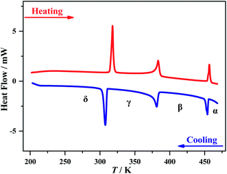
Thermogravimetric analysis showed that 1 is stable up to 495 K under a nitrogen atmosphere (Fig. S2†). Three structural phase transitions were detected by DSC (Fig. 1), as clearly indicated by three reversible thermal anomalies at 455/457 K (T1), 384/383 K (T2), and 311/315 K (T3) during the cooling/heating runs, respectively. The total entropy changes (ΔS) of the three phase transitions in the cooling process are estimated to be 5.0, 11.6, and 24.1 J mol−1 K−1, respectively. For convenience, we use α, β, γ, and δ to label the phases above T1, between T1 and T2, between T2 and T3, and below T3, respectively.Crystal structures for the four phases
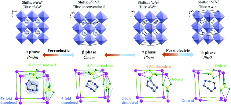
To understand the step-by-step structural phase transitions, variable-temperature single-crystal X-ray diffractions were performed for the four phases of 1. As shown in Fig. 2, the crystal structure of 1 can be topologically assigned as an ABX3-type perovskite structure. Each K+ ion acting as a B-site component is coordinated by twelve F atoms from six adjacent tetrafluoroborates, all of which act as X-site bridging ligands linking two adjacent K+ ions, thus leading to a three-dimensional cage-like inorganic host framework constructed by corner-sharing K(BF4)6 octahedra. Each organic cation residing in each cage acts as an A-site component in the perovskite structure.By and large, the three-step phase transitions at decreasing temperatures are highly associated with the gradually frozen molecular dynamics of H2hpz2+ cations and cooperative deformation of the [K(BF4)3]2− inorganic framework. In detail, the α phase crystallizes in the cubic space group Pm![[3 with combining macron]](https://www.rsc.org/images/entities/char_0033_0304.gif) m (no. 221) which is the prototype of an ideal perovskite structure without any deformation. As required by the imposed crystallographic symmetry, the organic cations are 48-fold dynamically disordered in almost arbitrary orientations, and the BF4− bridges are 16-fold disordered. In the β phase, an obvious deformation of the framework occurs, including column shifts of connected KX6 octahedra, tilting distortions between adjacent octahedra, and displacements inside the octahedra,40–43 among which the column shifts with an extended Glazer's notation of aXaXc0, via coupling with the latter two parts, resulting in the space group Cmcm (no. 63) for the β phase. Consequently, the organic cations become 4-fold disordered about two mirror planes perpendicular to the a- and c-axes, respectively, and all the BF4− bridges are disordered over four sites.
m (no. 221) which is the prototype of an ideal perovskite structure without any deformation. As required by the imposed crystallographic symmetry, the organic cations are 48-fold dynamically disordered in almost arbitrary orientations, and the BF4− bridges are 16-fold disordered. In the β phase, an obvious deformation of the framework occurs, including column shifts of connected KX6 octahedra, tilting distortions between adjacent octahedra, and displacements inside the octahedra,40–43 among which the column shifts with an extended Glazer's notation of aXaXc0, via coupling with the latter two parts, resulting in the space group Cmcm (no. 63) for the β phase. Consequently, the organic cations become 4-fold disordered about two mirror planes perpendicular to the a- and c-axes, respectively, and all the BF4− bridges are disordered over four sites.
With further cooling to the γ phase, the organic cations are frozen to be 2-fold disordered and two thirds of the BF4− bridges are frozen in an ordered state. Meanwhile K+ ions are slightly displaced in the ab plane, eventually resulting in a deformation of the framework with unconventional tilts (Fig. S10†) and the lower-symmetric space group Pbcm (no. 57) for the γ phase. Moreover, when cooling 1 into the δ phase, a multiple tilting distortion with Glazer's notation a−a−c−, together with an intra-octahedron displacement of K+ ion towards one of the eight faces of K(BF4)6 octahedron, intensifies the deformation of the inorganic framework. More importantly, such a deformed framework hosts the polar organic cations in an orientationally ordered manner, which gives rise to a spontaneous electric polarization in the δ phase belonging to the polar space group Pbc21 (no. 29). It is noted that the tilts and displacements that occur in the δ phase are the same as those observed in inorganic perovskite ferroelectric NaNbO3,44 implying that the deformation of the inorganic framework in 1 makes an important contribution to the spontaneous polarization as well.
In short, with decreasing temperature from 463 K to room temperature, the space group of 1 transforms from Pm![[3 with combining macron]](https://www.rsc.org/images/entities/char_0033_0304.gif) m (no. 221) into Cmcm (no. 63), then Pbcm (no. 57), and finally to Pbc21 (no. 29), including a ferroelastic and a ferroelectric phase transition with Aizu notation of m3mFmmm and mmmFmm2,45 respectively (vide infra). Such dynamic transition of molecular components from a “melt-like” state at high temperature to a frozen state at low temperature was similarly observed in other molecular perovskites,46,47 but 1 is a unique one that displays multi-step phase transitions to host both ferroelectric and ferroelastic orders (vide infra), benefiting from the delicate interplay between the frozen organic cations and the synchronously deformed inorganic framework.
m (no. 221) into Cmcm (no. 63), then Pbcm (no. 57), and finally to Pbc21 (no. 29), including a ferroelastic and a ferroelectric phase transition with Aizu notation of m3mFmmm and mmmFmm2,45 respectively (vide infra). Such dynamic transition of molecular components from a “melt-like” state at high temperature to a frozen state at low temperature was similarly observed in other molecular perovskites,46,47 but 1 is a unique one that displays multi-step phase transitions to host both ferroelectric and ferroelastic orders (vide infra), benefiting from the delicate interplay between the frozen organic cations and the synchronously deformed inorganic framework.
Ferroelastic phase transition and spontaneous strain
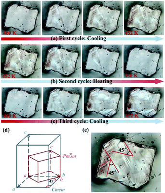
During the α → β transition, a symmetry break occurs with the total symmetry decreasing from forty-eight symmetric elements (E, 8C3, 6C4, 6C2, 3C2′, i, 6S4, 8S6, 3σh, and 6σd) in point group Oh to eight elements (E, C2, 2C2′, i, σh, and 2σv) in point group D2h, which is a ferroelastic transition with an Aizu notation of m3mFmmm(ss) or m3mFmmm(pp). From the cubic paraelastic phase (α) to the orthorhombic ferroelastic phase (β), the c-axis length is doubled, and the diagonals b − a and a + b in the cubic phase become the a- and b-axes in the orthorhombic phase, respectively (Fig. 3e). Such a relationship between the unit cells of paraelastic and ferroelastic phases was similarly observed in inorganic crystals KCN and NaCN,49 and they should be classified as a m3mFmmm(ss) ferroelastic species, in which two of three mirror planes of the ferroelastic phase (β) are along the mirror planes making an angle of 45° to the tetrad axes of the paraelastic phase (α).45To further verify the ferroelastic phase transition, the variation of domains between α and β phases was inspected using a polarizing microscope on a single crystal of 1 along its c-axis (Fig. S9†). As shown in Fig. 3a, the single crystal without any external strain reveals a mono-domain morphology at 460 K (i.e., in paraelastic phase). During the α → β transition, via cooling the crystal to 452 K, four kinds of recognizable striated domains mixed up with some dim areas appeared and extended gradually to the entire crystal. The domain walls intersecting at angles of 45° and 90° (Fig. 3e) well match with the aforementioned transformation of unit cells during this ferroelastic transition (Fig. 3d). When the crystal was heated back to 460 K, these striated domains fade out and the mono-domain state was recovered (Fig. 3b). Such a process is repeatable, as confirmed by the appearance of multi-domain structures when the crystal was cooled again to the β phase (Fig. 3c). It should be noted that, for a m3mFmmm(ss) ferroelastic species, the number of orientation states in the ferroelastic phase is equal to the order of the point group Oh divided by the order of the point group D2h, which is six for the β phase, including the four orientation states in the present domains observed along the c-axis.48
In addition, for the present m3mFmmm(ss) species, based on the aforementioned lattice parameters measured at 463 K and 400 K, a total spontaneous strain is estimated by:
Ferroelectric phase transition and spontaneous polarization
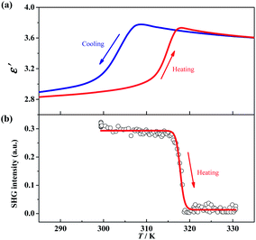
The γ → δ transition belongs to a ferroelectric transition with an Aizu notation of mmmFmm2, during which the number of total symmetric elements decreases from eight (E, C2, 2C2′, i, σh, and 2σv) in point group D2h to four (E, C2, and 2σv) in point group C2v. Such a change in the number of symmetric elements implies that 1 is a uniaxial ferroelectric in its room-temperature phase. To further confirm the ferroelectric ordering for the δ phase, dielectric, SHG, and PFM measurements were performed.The temperature-dependent dielectric permittivity (ε = ε′ + iε″) was evaluated in the range of 285–335 K on the powder-pressed sample of 1. As shown in Fig. 4a, the real part of the dielectric permittivity exhibits a fast step-like response around T3 (from γ to δ phase), varying from a relatively higher dielectric state (ca. 3.6 for γ phase) to a relatively lower dielectric state (ca. 2.9 for δ phase) upon cooling. The tendency is inverted in a heating process, and a thermal hysteresis of 11.8 K was observed, in agreement with the reversible phase transition observed by DSC measurements. Such a step-like dielectric anomaly during a ferroelectric phase transition is a unique characteristic of an improper ferroelectric.
Variable-temperature SHG measurements were performed on the polycrystalline sample of 1. As shown in Fig. 4b, at the δ phase (below 310 K), the SHG intensity is nonzero (about 0.3 times of KH2PO4), i.e., SHG being activated. When heating the sample to above 320 K (γ phase), the SHG intensity decreases to almost zero, i.e., SHG being silenced. Such SHG switch suggests a structural phase transition from a non-centrosymmetric one to a centrosymmetric one, and well matches with the change of the space group between the δ (Pbc21) and γ (Pbcm) phases observed in single-crystal X-ray diffraction.
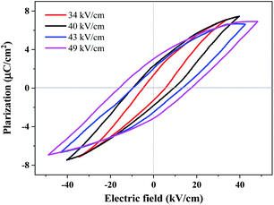
Ferroelectric polarization reversal was further evidenced by the P–E hysteresis loops (Fig. 5), which were obtained by measurements performed on a single crystal with 0.18 mm thickness using a modified Saywer–Tower circuit under a varying electric field up to 49 kV cm−1, giving an estimated spontaneous polarization of 4.8 µC cm−2 by the extrapolation method. It should be noted that, the spontaneous electric polarization was increased by increasing the electric field from 34 to 49 kV cm−1 (Fig. S12†), probably owing to the relatively large and gradually increased leakage currents under these electric fields, and the spontaneous polarization of 4.8 µC cm−2 at an electric field of 49 kV cm−1 was not saturated yet. Unfortunately, applying a higher electric field caused a short-cut current and the breakdown of the crystals, probably owing to the crystal defects and frangibility. In addition, the technical difficulty to apply an electric field exactly along the polar axis of the test crystal for such a uniaxial ferroelectric may also cause such kind of slanted P–E loops.
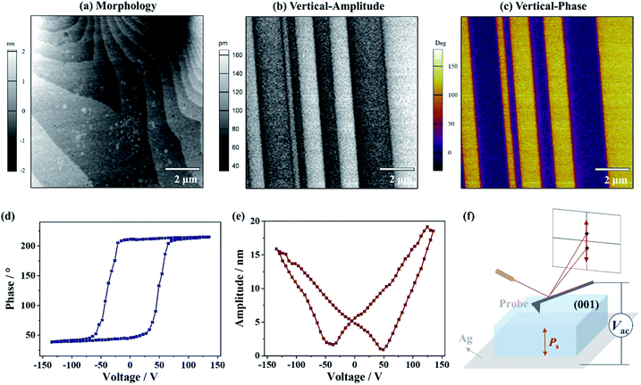
To gain an insight into the distinct polarization directions of ferroelectric domains in the δ phase, the vertical and lateral PFM (VPFM and LPFM) mappings on the same area of a single crystal of 1 were obtained simultaneously, by applying a voltage perpendicular to the (001) plane (Fig. 6f). In the VPFM mode, an obvious bipolar domain pattern emerged in the phase image (Fig. 6c), suggesting the existence of two different polarization directions with an angle of 180° in the regions. Subsequently, the VPFM and LPFM mappings on the nearby area were obtained, from which the VPFM phase image shows a bipolar domain pattern while the LPFM one shows an approximate single-domain state (Fig. S8†). The different domain distributions between the VPFM and LPFM modes match well with the two supposed anti-parallel polarization directions in such a uniaxial ferroelectric being orientated along its polar axis, i.e., the c-axis. Moreover, when a voltage of 135 V was applied, a rectangle-shape phase loop (Fig. 6d) and a butterfly-shape amplitude loop (Fig. 6e) representing a typical characteristic for the 180° polarization switching of domains were observed, further supporting ferroelectricity for the δ phase.
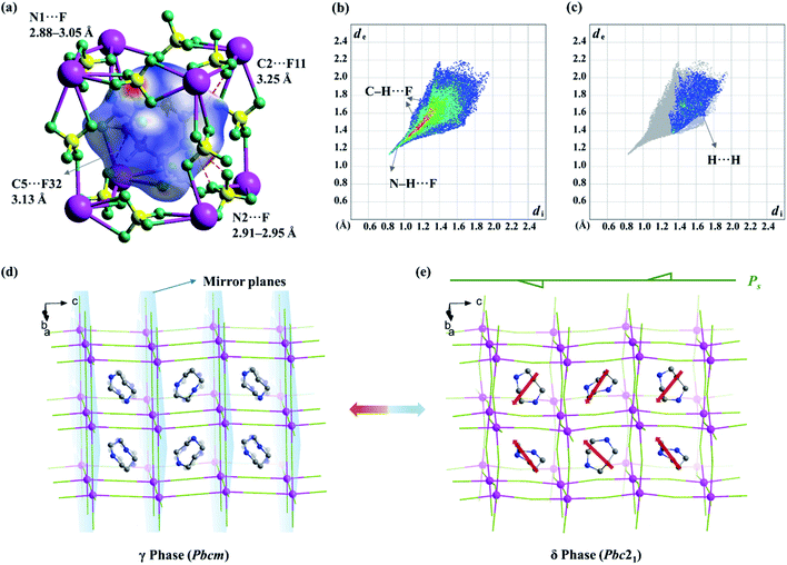
To further find out the underlying mechanism for the spontaneous polarization along the c-axis, Hirshfeld surface analysis50 was performed for the organic cation in the δ phase. As shown in Fig. 7b and c, the N–H⋯F and C–H⋯F interactions are associated with about 88% of the Hirshfeld surface area, making a major contribution to the host–guest interactions, while the H⋯H contacts are associated with the rest 12% area, contributing to the guest–guest interactions. As shown in the Hirshfeld surfaces mapped with a normalized contact distance (dnorm, Fig. 7a), in which the contacts shorter and longer than van der Waals separations are shown as red and blue spots, respectively, the red spots are found to be mostly associated with the hydrogen-bonding interactions (or weak non-classic hydrogen-bonding interactions), such as N1–H⋯F (N1⋯F distance: 2.88–3.05 Å), N2–H⋯F (2.91–2.95 Å), C2–H⋯F11 (3.25 Å), and C5–H⋯F32 (3.13 Å), representing the main strong host–guest interactions between organic cations and the inorganic framework.
In the fingerprint plot (Fig. 7b) representing the distances from the surface to the nearest nucleus inside and outside the surface with individual (di, de) pairs, as shown in Fig. 7b, the left bottom region with a minimal (di, de) ≈ (0.8–1.0 Å, 1.1–1.3 Å) indicated that the strongest contacts are mainly associated with N–H⋯F contacts, while the points marked in red (indicating a large number of contacts) are mainly associated with C–H⋯F contacts. In comparison, for the paraelectric γ phase, both the red and green regions, corresponding to both C–H⋯F and N–H⋯F contacts, respectively, are distributed more dispersedly (Fig. S6†), owing to the 2-fold positional disorder of organic cations.
The above information suggested that the host–guest interactions, i.e., the strongest interactions produced by the two –NH2– groups of the H2hpz2+ cation and numerous additional weak interactions produced by the five –CH2– groups, lead to the polar orientation of the guest cation in the δ phase. In detail, two –NH2– groups point exactly to the two BF4− bridges parallel to the diagonal of the unit cage and the ordered cation slantwise resides in the cage. As a result, the oriented ordered arrangement of the polar H2hpz2+ cations together with an aforementioned deformation of the inorganic framework breaks the mirror symmetry and gives rise to spontaneous polarization along the c-axis in the δ phase (Fig. 7d and e). By contrast, the reported analogue, (H2mdabco)(NH4)(BF4)3,35 containing a similar polar A-site cation with a dipole moment of ca. 1.6 D, undergoes a ferroelastic phase transition (with an Aizu notation of m3mF![[3 with combining macron]](https://www.rsc.org/images/entities/char_0033_0304.gif) m) but not a ferroelectric one, as the adjacent branch-like rigid H2mdabco2+ cations adopt an opposite direction to cancel polarization. In another analogue, (H2pz)[Na(BF4)3],34 the only one instance revealing a polar crystal structure (P43), its flexible A-site H2pz2+ cations adopt a weak-dipolar configuration (ca. 0.02 D), and thus its polarity is mainly generated by the slight deformation of the framework. These facts suggest that, distinguishing from the H2pz2+ and H2mdabco2+ cations, the H2hpz2+ cation combines a relatively larger dipole moment (ca. 2.1 D) and a more easily changeable configuration, and hence plays a crucial role in matching or inducing delicate framework deformation and eventually generating a reversible spontaneous polarization, i.e., ferroelectricity, for 1.
m) but not a ferroelectric one, as the adjacent branch-like rigid H2mdabco2+ cations adopt an opposite direction to cancel polarization. In another analogue, (H2pz)[Na(BF4)3],34 the only one instance revealing a polar crystal structure (P43), its flexible A-site H2pz2+ cations adopt a weak-dipolar configuration (ca. 0.02 D), and thus its polarity is mainly generated by the slight deformation of the framework. These facts suggest that, distinguishing from the H2pz2+ and H2mdabco2+ cations, the H2hpz2+ cation combines a relatively larger dipole moment (ca. 2.1 D) and a more easily changeable configuration, and hence plays a crucial role in matching or inducing delicate framework deformation and eventually generating a reversible spontaneous polarization, i.e., ferroelectricity, for 1.
Conclusions
In summary, by using a polar cation with a relatively large dipole moment and an easy changeable conformation, i.e., H2hpz2+, as an A-site cation to assemble with potassium tetrafluoroborate, we successfully obtained a new ABX3-type tetrafluoroborate-based molecular perovskite, i.e., 1, which undergoes three-step phase transitions at 455 K, 384 K, and 311 K, respectively. By cooling the prototype cubic phase in which the A-site and X-site components are highly disordered, a stepwise change of molecular dynamics occurs, resulting in a ferroelastic phase featuring six equivalent ferroelastic domain states accompanied by an estimated spontaneous strain of 0.046. On further cooling the ferroelastic phase to room temperature, the organic cations are frozen thoroughly, resulting in ferroelectricity with a typical bipolar ferroelectric domain pattern. Such stepwise ferroelastic and ferroelectric phase transitions in 1 benefit from the delicate interplay between the gradually frozen organic cations and the cooperatively deformed inorganic framework. As a unique instance with the coexistence of room-temperature ferroelastic and ferroelectric orders among the known molecular perovskites based on diverse bridges, 1 serves as an interesting example demonstrating a successful strategy to assemble high-temperature molecular multiferroics. Moreover, the present study provides important clues to guide the rational choosing of suitable organic cations and matchable B-site cations to assemble more advanced functional molecular perovskites based on tetrafluoroborate and other similar bridges.Author contributions
W.-X. Zhang, X.-M. Chen and X.-X. Chen conceived the idea, designed the experiments and co-wrote the manuscript. X.-X. Chen performed the synthesis experiments, the Hirshfeld analysis, and the measurements of DSC, SHG, dielectric permittivity, crystal structures, ferroelastic domains and P-E hysteresis loops. X.-Y. Zhang and L.-Q. Xiong performed the PFM measurements. D.-X. Liu, R.-K. Huang and S.-S. Wang assisted the data collection and reduction of the variable-temperature crystal structures.Conflicts of interest
There are no conflicts to declare.Acknowledgements
This work was supported by the NSFC (22071273 and 21821003), and Local Innovative and Research Teams Project of Guangdong Pearl River Talents Program (2017BT01C161). We thank the staff of the BL17B beamlines at the National Centre for Protein Sciences Shanghai and Shanghai Synchrotron Radiation Facility, Shanghai, People's Republic of China, for assistance during data collection.Notes and references
- W. Prellier, M. P. Singh and P. Murugavel, J. Phys.: Condens. Matter, 2005, 17, R803–R832 CrossRef CAS.
- H. Bea, B. Dupe, S. Fusil, R. Mattana, E. Jacquet, B. Warot-Fonrose, F. Wilhelm, A. Rogalev, S. Petit, V. Cros, A. Anane, F. Petroff, K. Bouzehouane, G. Geneste, B. Dkhil, S. Lisenkov, I. Ponomareva, L. Bellaiche, M. Bibes and A. Barthelemy, Phys. Rev. Lett., 2009, 102, 217603 CrossRef CAS PubMed.
- Y. Tokunaga, N. Furukawa, H. Sakai, Y. Taguchi, T. H. Arima and Y. Tokura, Nat. Mater., 2009, 8, 558–562 CrossRef CAS PubMed.
- J. F. Scott, Science, 2007, 315, 954–959 CrossRef CAS PubMed.
- S. Horiuchi and Y. Tokura, Nat. Mater., 2008, 7, 357–366 CrossRef CAS PubMed.
- G. F. Nataf, M. Guennou, J. M. Gregg, D. Meier, J. Hlinka, E. K. H. Salje and J. Kreisel, Nat. Rev. Phys., 2020, 2, 634–648 CrossRef CAS.
- M. Owczarek, K. A. Hujsak, D. P. Ferris, A. Prokofjevs, I. Majerz, P. Szklarz, H. Zhang, A. A. Sarjeant, C. L. Stern, R. Jakubas, S. Hong, V. P. Dravid and J. F. Stoddart, Nat. Commun., 2016, 7, 13108 CrossRef CAS PubMed.
- L. W. Martin and A. M. Rappe, Nat. Rev. Mater., 2017, 2, 16087 CrossRef CAS.
- G.-K. Long, R. Sabatini, M. I. Saidaminov, G. Lakhwani, A. Rasmita, X.-G. Liu, E. H. Sargent and W.-B. Gao, Nat. Rev. Mater., 2020, 5, 423–439 CrossRef.
- O. Sato, Nat. Chem., 2016, 8, 644–656 CrossRef CAS PubMed.
- Q. Pan, Z.-B. Liu, Y.-Y. Tang, P.-F. Li, R.-W. Ma, R.-Y. Wei, Y. Zhang, Y.-M. You, H.-Y. Ye and R.-G. Xiong, J. Am. Chem. Soc., 2017, 139, 3954–3957 CrossRef CAS PubMed.
- H.-Y. Ye, Y.-Y. Tang, P.-F. Li, W.-Q. Liao, J.-X. Gao, X.-N. Hua, C. Hu, P.-P. Shi, Y.-M. You and R.-G. Xiong, Science, 2018, 361, 151–155 CrossRef CAS PubMed.
- Y.-Y. Tang, P.-F. Li, W.-Q. Liao, P.-P. Shi, Y.-M. You and R.-G. Xiong, J. Am. Chem. Soc., 2018, 140, 8051–8059 CrossRef CAS PubMed.
- H.-Y. Zhang, Y.-Y. Tang, P.-P. Shi and R.-G. Xiong, Acc. Chem. Res., 2019, 52, 1928–1938 CrossRef CAS PubMed.
- W. Li, Z.-M. Wang, F. Deschler, S. Gao, R. H. Friend and A. K. Cheetham, Nat. Rev. Mater., 2017, 2, 16099 CrossRef.
- W. Li, A. Stroppa, Z.-M. Wang and S. Gao, Hybrid organic–inorganic perovskites, WILEY-VCH Verlag GmbH & Co. KGaA, 2020 Search PubMed.
- W.-J. Xu, S. Kopyl, A. Kholkin and J. Rocha, Coord. Chem. Rev., 2019, 387, 398–414 CrossRef CAS.
- P. Jain, V. Ramachandran, R. J. Clark, H.-D. Zhou, B. H. Toby, N. S. Dalal, H. W. Kroto and A. K. Cheetham, J. Am. Chem. Soc., 2009, 131, 13625–13627 CrossRef CAS PubMed.
- M.-M. Zhao, L. Zhou, P.-P. Shi, X. Zheng, X.-G. Chen, J.-X. Gao, L. He, Q. Ye, C.-M. Liu and D.-W. Fu, Chem.–Eur. J., 2019, 25, 6447–6454 CrossRef CAS PubMed.
- L. C. Gomez-Aguirre, B. Pato-Doldan, A. Stroppa, L. M. Yang, T. Frauenheim, J. Mira, S. Yanez-Vilar, R. Artiaga, S. Castro-Garcia, M. Sanchez-Andujar and M. A. Senaris-Rodriguez, Chem.–Eur. J., 2016, 22, 7863–7870 CrossRef CAS PubMed.
- X.-H. Zhao, X.-C. Huang, S.-L. Zhang, D. Shao, H.-Y. Wei and X.-Y. Wang, J. Am. Chem. Soc., 2013, 135, 16006–16009 CrossRef CAS PubMed.
- Y.-Z. Hu, L. You, B. Xu, T. Li, S. A. Morris, Y.-X. Li, Y.-H. Zhang, X. Wang, P. S. Lee, H.-J. Fan and J.-L. Wang, Nat. Mater., 2021, 20, 612–617 CrossRef CAS PubMed.
- W.-J. Xu, Z.-Y. Du, W.-X. Zhang and X.-M. Chen, CrystEngComm, 2016, 18, 7915–7928 RSC.
- W.-J. Xu, P.-F. Li, Y.-Y. Tang, W.-X. Zhang, R.-G. Xiong and X.-M. Chen, J. Am. Chem. Soc., 2017, 139, 6369–6375 CrossRef CAS PubMed.
- Z.-Y. Du, T.-T. Xu, B. Huang, Y.-J. Su, W. Xue, C.-T. He, W.-X. Zhang and X.-M. Chen, Angew. Chem., Int. Ed., 2015, 54, 928–932 CrossRef.
- K.-P. Xie, W.-J. Xu, C.-T. He, B. Huang, Z.-Y. Du, Y.-J. Su, W.-X. Zhang and X.-M. Chen, CrystEngComm, 2016, 18, 4495–4498 RSC.
- C. Shi, J.-J. Ma, J.-Y. Jiang, M.-M. Hua, Q. Xu, H. Yu, Y. Zhang and H.-Y. Ye, J. Am. Chem. Soc., 2020, 142, 9634–9641 CAS.
- M. Mączka, A. Gągor, M. Ptak, D. Stefańska and A. Sieradzki, Phys. Chem. Chem. Phys., 2018, 20, 29951–29958 RSC.
- S.-S. Wang, X.-X. Chen, B. Huang, R.-K. Huang, W.-X. Zhang and X.-M. Chen, CCS Chem., 2019, 1, 448–454 CrossRef CAS.
- S.-L. Chen, Z.-R. Yang, B.-J. Wang, Y. Shang, L.-Y. Sun, C.-T. He, H.-L. Zhou, W.-X. Zhang and X.-M. Chen, Sci. China Mater., 2018, 61, 1123–1128 CrossRef CAS.
- Y. Shang, R.-K. Huang, S.-L. Chen, C.-T. He, Z.-H. Yu, Z.-M. Ye, W.-X. Zhang and X.-M. Chen, Cryst. Growth Des., 2020, 20, 1891–1897 CrossRef CAS.
- W.-X. Zhang, S.-L. Chen, Y. Shang, Z.-H. Yu and X.-M. Chen, Energy Mater. Front., 2020, 1, 123–135 CrossRef.
- G.-Z. Liu, J. Zhang and L.-Y. Wang, Synth. React. Inorg., Met.-Org., Nano-Met. Chem., 2011, 41, 1091–1094 CrossRef CAS.
- Y.-L. Sun, X.-B. Han and W. Zhang, Chem.–Eur. J., 2017, 23, 11126–11132 CrossRef CAS PubMed.
- G.-M. Fan, C. Shi, L. Qiao, H.-J. Li and H.-Y. Ye, J. Mater. Chem. C, 2018, 6, 8349–8352 RSC.
- L. Ye, Z.-X. Gong, C. Shi, J.-J. Ma, H. Liang, F.-W. Qi, D.-Y. E, C.-F. Wang, Y. Zhang and H.-Y. Ye, CrystEngComm, 2019, 21, 7043–7047 RSC.
- L.-L. Chu, T. Zhang, W.-Y. Zhang, P.-P. Shi, J.-X. Gao, Q. Ye and D.-W. Fu, J. Phys. Chem. Lett., 2020, 11, 1668–1674 CrossRef CAS PubMed.
- O. V. Dolomanov, L. J. Bourhis, R. J. Gildea, J. A. K. Howard and H. Puschmann, J. Appl. Crystallogr., 2009, 42, 339–341 CrossRef CAS.
- G. M. Sheldrick, Acta Crystallogr., Sect. C: Struct. Chem., 2015, 71, 3–8 Search PubMed.
- A. M. Glazer, Acta Crystallogr., Sect. B: Struct. Crystallogr. Cryst. Chem., 1972, 28, 3384–3392 CrossRef CAS.
- A. L. Goodwin, Phys. Rev. B: Solid State, 2006, 74, 134302 CrossRef.
- H. L. Bostrom, J. A. Hill and A. L. Goodwin, Phys. Chem. Chem. Phys., 2016, 18, 31881–31894 RSC.
- S. G. Duyker, J. A. Hill, C. J. Howard and A. L. Goodwin, J. Am. Chem. Soc., 2016, 138, 11121–11123 CrossRef CAS PubMed.
- A. M. Glazer and K. Ishida, Ferroelectrics, 1974, 6, 219–224 CrossRef CAS.
- K. Aizu, J. Phys. Soc. Jpn., 1969, 27, 387–396 CrossRef CAS.
- Z.-Y. Du, Y.-P. Zhao, C.-T. He, B.-Y. Wang, W. Xue, H.-L. Zhou, J. Bai, B. Huang, W.-X. Zhang and X.-M. Chen, Cryst. Growth Des., 2014, 14, 3903–3909 CrossRef CAS.
- S.-Y. Zhang, X. Shu, Y. Zeng, Q.-Y. Liu, Z.-Y. Du, C.-T. He, W.-X. Zhang and X.-M. Chen, Nat. Commun., 2020, 11, 2752 CrossRef CAS PubMed.
- J. Sapriel, Phys. Rev. B: Solid State, 1975, 12, 5128–5140 CrossRef CAS.
- Y.-S. Zhao, D. J. Weidner, J. B. Parise and D. E. Cox, Phys. Earth Planet. Inter., 1993, 76, 17–34 CrossRef CAS.
- M. A. Spackman and D. Jayatilaka, CrystEngComm, 2009, 11, 19–32 RSC.
Footnote |
| † Electronic supplementary information (ESI) available: Additional data and a video of ferroelastic domain evolution. CCDC 1988358, 1988359, 1988360 and 1988361. For ESI and crystallographic data in CIF or other electronic format see DOI: 10.1039/d1sc01345a |
| This journal is © The Royal Society of Chemistry 2021 |

