Photophysics and photochemistry with Earth-abundant metals – fundamentals and concepts†‡
Christoph
Förster
 * and
Katja
Heinze
 *
*
Department of Chemistry, Johannes Gutenberg University of Mainz, Duesbergweg 10-14, D-55128, Mainz, Germany. E-mail: cfoerster@uni-mainz.de; katja.heinze@uni-mainz.de
First published on 6th February 2020
Abstract
Recent exciting developments in the area of mononuclear photoactive complexes with Earth-abundant metal ions (Cu, Zr, Fe, Cr) for potential eco-friendly applications in (phosphorescent) organic light emitting diodes, in imaging and sensing systems, in dye-sensitized solar cells and as photocatalysts are presented. Challenges, in particular the extension of excited state lifetimes, and recent conceptual breakthroughs in substituting precious and rare-Earth metal ions (e.g. Ru, Ir, Pt, Au, Eu) in these applications by abundant ions are outlined with selected examples. Relevant fundamentals of photophysics and photochemistry are discussed first, followed by conceptual and instructive case studies.
Key learning points(1) Photoactive electronically excited states should be weakly distorted (e.g. spin–flip states of 3d3-CrIII ions; rigidified metal-to-ligand charge transfer states of 3d10-CuI complexes) to achieve nested states and consequently long excited state lifetimes and/or high emission quantum yields.(2) Non-emissive, distorted and often short-lived metal-centered excited states should be energetically and geometrically separated from the photoactive states. This is especially challenging for metal ions with 3d1–3d9 electron configuration with intrinsically weak ligand field strengths (e.g. 3d3-CrIII, 3d5-FeIII, 3d6-FeII, 3d6-Cr0) and requires purposefully designed ligands. (3) Absence of metal-centered states in d0 and d10 complexes can lead to photoactive complexes, e.g. 3d10-CuI (metal-to-ligand charge transfer) and 4d0- ZrIV-complexes (ligand-to-metal charge transfer). (4) Adjustable parameters in a conceptual ligand design are the donor and acceptor abilities and geometric preferences to control the ligand field strength (e.g. 3d3-CrIII, 3d5-FeIII, 3d6-FeII, 3d6-Cr0), the electronic nature of the ligand to tune the energy of charge transfer states (e.g. FeII, FeIII, CuI, ZrIV) and the steric congestion and rigidity of the ligand backbone to diminish geometric reorganization in the excited states (FeII, FeIII, CuI). (5) For low-energy excited states (near-infrared emitters), high-energy oscillators (C–H, N–H, O–H) in the proximity of the involved orbitals in electronic transitions should be avoided to diminish multiphonon relaxation via the X–H overtones. X–H oscillators can be eliminated by ligand and solvent deuteration (e.g. CrIII). |
1. Introduction
Currently, approximately 80% of the energy consumed by mankind stems from limited fossil sources, namely oil, gas and coal. Combustion processes produce large amounts of carbon dioxide as greenhouse gas and air pollutants, such as nitric oxides NOx or sulfur dioxide SO2.1 A sustainable alternative energy source is sunlight, by converting solar energy to electricity in photovoltaics, e.g. in dye-sensitized solar cells (DSSCs),2 or by converting solar energy to chemical energy in photochemical/photocatalytic reactions.3–6 Beyond changing the energy supply, it is necessary to reduce the consumer's energy demand by using energy efficient devices, e.g. OLEDs (organic light-emitting diodes) and PHOLEDs (phosphorescent organic light-emitting diodes) as light-sources7–9 and by powering chemical reactions with light instead of thermal energy on larger scales.3–6 In these applications, transition metal complexes of the precious metals, e.g. Ru, Ir, Pt or Au, as well as rare-Earth elements (lanthanides) are typically employed due to their favourable photophysical properties. Due to the very low abundance (Fig. 1) and concomitant high costs, the energy transition to sustainable sources can be only partially accomplished with the use of precious metals, especially with iridium as the least abundant stable element on Earth (ESI,‡ Table S1).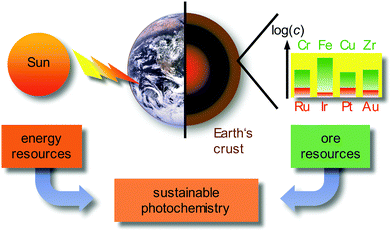 | ||
| Fig. 1 Sustainable photochemistry as a combination of sustainable energy sources and resource-efficient Earth-abundant metals. | ||
Employing precious and rare-Earth metals is furthermore geopolitically problematic with only a few mining and producing countries. In addition, mining, extraction and separation is highly energy and water consuming, sometimes even employing very toxic agents (such as cyanide or mercury in gold mining). Consequently, the use of Earth-abundant metals, e.g. most first row transition metals (3d elements) and certain second row transition metals, would be more sustainable (Fig. 1).10 For a comprehensive sustainable photochemistry in medium- to large-scale applications, it is mandatory to combine sustainable energy sources (sunlight) with resource-efficient Earth-abundant elements, e.g. 3d elements such as chromium, iron or copper in respective devices and applications (Fig. 1).
The development of 3d metal complexes as emitters for (PH)OLEDs, as dyes for DSSCs or as photocatalysts is very challenging, due to the typically fast non-radiative deactivation of the electronically excited states and the lability of the ligands in these complexes. Sustainable applications of photoactive metal complexes rely on two essential requirements. The complexes should be thermally stable and photostable and the relevant electronically excited states should possess a sufficiently long lifetime to display luminescence or to interact with a substrate in photocatalysis or with a semiconductor in DSSCs. These requirements are particularly challenging to achieve with 3d metal ions and this has prevented their widespread application up to now.11
2. Photophysical background
For a conceptual design of molecular photoactive metal complexes in DSSCs, (PH)OLEDs and photocatalysts, it is essential to understand the underlying photophysical and photochemical processes.3,12–16 To introduce the fundamentals of photochemistry it is helpful to identify the relevant electronic states of metal complexes with simple one-electron orbital sketches, the microstates.The concept “structure/bonding/states” connects molecular structure (molecular symmetry), the bonding situation, which is identified by microstates (one-electron approximation) and resulting electronic states (multi-electron description). The interplay of “structure/bonding/states” forms the basis for a conceptual (ligand and complex) design to tailor the photophysical and -chemical properties of photoactive transition metal complexes, namely the nature of excited states, the excited state energies, lifetimes and redox potentials.
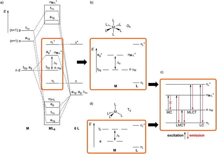
The relevant frontier orbitals, essentially metal-centered (MC) and ligand-centered orbitals, are extracted from the well-known molecular orbital diagram of octahedral transition metal complexes ML6 (or analogous diagrams for other point groups, structure) (Fig. 2a, b and d). Filling in the appropriate number of electrons generates the relevant microstates (bonding). With this simplified description by microstates, electronic transitions and electronic states of metal complexes can be straightforwardly described (Fig. 2c). Metal-centered (MC) or ligand field states arise from electronic transitions within the d manifold, ligand-centered (LC) states from transitions between occupied and unoccupied ligand-centered orbitals (e.g. π–π*), while charge-transfer (CT) states involve metal and ligand localized orbitals. Metal-to-ligand charge transfer (MLCT) states evolve from transitions between occupied d orbitals and unoccupied ligand orbitals and ligand-to-metal charge transfer (LMCT) states involve occupied ligand and unoccupied metal orbitals (Fig. 2c).
Although MC transitions are forbidden in complexes with inversion symmetry (Laporte's rule),15 these transitions become partially allowed by dynamic symmetry lowering and in complexes of lower symmetry, e.g. tetrahedral or heteroleptic complexes without inversion symmetry. In the following sections, the notation of the Oh and Td point groups for complexes with local octahedral and tetrahedral geometry, respectively (structure), is applied both for molecular orbitals (Oh: t2g/eg; Td: e, t2; bonding) and for spectroscopic terms (Oh: 3T1g, 2Eg, etc.; states) for didactic reasons, even if the actual overall symmetry of the considered complexes is lower.
As electronic transitions are essentially instantaneous compared with the time scale of nuclear motions, the geometry of a metal complex does not change during the excitation. The excited state reached is called Franck–Condon state (vertical transition, Franck–Condon principle).14 However, as the spatial electron density of the molecule has changed, the nuclei follow the new electron density, which leads to a new minimum geometry of the complex (bonding/structure). A combination of normal modes (vibrational cooling, VC) describes the change of geometry, namely distances, angles and torsional angles. For example, population of antibonding orbitals by electronic excitation lengthens the corresponding bond(s).
Consequently, to describe electronic transitions and their consecutive reactions, the nuclear degrees of freedom have to be considered in a complete energy diagram. Typically, the 3N-6 degrees of freedom of a non-linear molecule with N atoms are reduced to a single relevant normal mode, e.g. the symmetric M–L stretching vibration of a complex MLn, or a combination of a few relevant normal modes. For such a simplified one-dimensional potential energy surface diagram, the harmonic approximation in the non-adiabatic representation is used in the following for clarity (Fig. 3).14,17 In this description, the intensity of a vibronic transition is proportional to the square of the overlap integral between the vibrational wavefunctions of the two states that are involved in the transition. This holds for both radiative transitions, namely absorption and emission.14 Non-radiative deactivation strongly depends on the vibrational overlap of electronic states as well. For nested states, i.e. states with similar geometry (Fig. 3a), the vibrational overlap for non-radiative decay is poor, the so-called weak coupling limit. On the other hand, with an appreciable horizontal displacement of the excited state potential, i.e. states with very different geometry (Fig. 3b), the vibrational overlap becomes significant. This leads to a higher rate constant for this non-radiative process (knr) in the so-called strong coupling limit. The probability for non-radiative decay also increases with decreasing energy difference of the ground and excited states, which is based on a larger vibrational overlap (Fig. 3a and c). Consequently, excited states with very low energy often decay rapidly to the ground state (GS), which is described by the so-called energy gap law.14 Non-radiative processes as internal conversion (IC, no spin change) and intersystem crossing (ISC, change of spin) are isoenergetic hopping processes between potential energy surfaces, followed by vibrational relaxation.
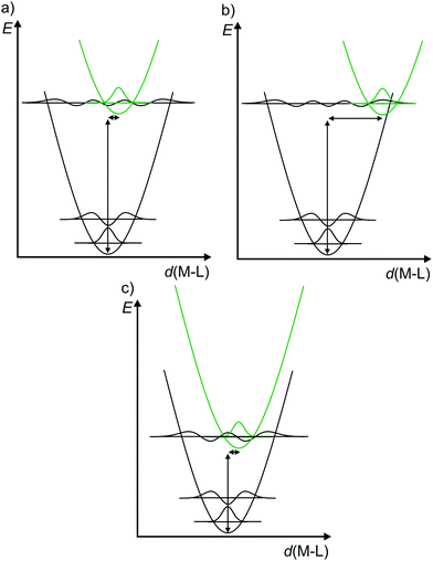 | ||
| Fig. 3 (a) Potential energy surface diagrams along a M–L normal mode with relevant vibrational wave functions for a nested excited state (weak vibrational wave function overlap), (b) a strongly distorted excited state (strong vibrational wave function overlap) and (c) for an energetically low-lying excited state (weakly distorted excited state but strong vibrational wave function overlap) (diagrams a and b adapted from ref. 14). | ||
The diagrams in Fig. 3 illustrate that both the excited state distortion and excited state energy play a decisive role in the non-radiative excited state decay. Both parameters should be controlled by chemical design.
3. Complexes with long-lived MLCT states
3.1 Low-spin 3d6, 4d6 and 5d6 complexes (iron(II), ruthenium(II), chromium(0) and iridium(III))
4d6 and 5d6 metal complexes, especially polypyridyl ruthenium(II)15,18–20 and cyclometalated iridium(III)15 complexes, are the work-horses in DSSCs2 (Ru), PHOLEDs7,8 (Ir) and photocatalysis (Ru, Ir).3,4 The photophysics of tris(2,2’-bipyridine)ruthenium(II) [Ru(bpy)3]2+ is based on a 1MLCT transition at λ ≈ 450 nm followed by fast intersystem crossing (kISC) to the 3MLCT state (Fig. 4a). The weakly distorted 3MLCT state is phosphorescent (λem ≈ 620 nm) in solution (Fig. 4a).18 The emission quantum yield Φem at 298 K in solution ranges between 0.018 under aerated (emission quenching by O2) and 0.095 under deaerated conditions in acetonitrile, respectively. The emission lifetimes amount to τem = 5 μs and 850 ns at 77 K and at r.t., respectively.18,19 These numbers indicate that a thermally activated non-radiative deactivation plays a significant role, especially at r.t. in solution.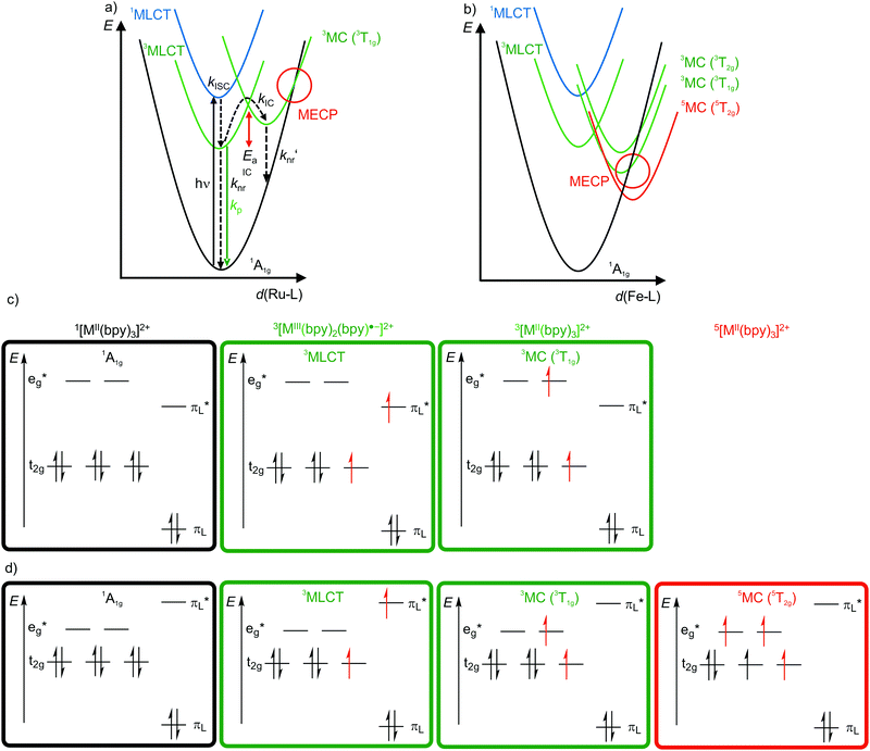 | ||
| Fig. 4 Schematic potential energy surface diagrams (adapted from ref. 19 and 22) of [M(bpy)3]2+ ((a) M2+ = Ru2+, (b) low-spin Fe2+) with relevant electronic states and photophysical processes with highlighted MECP's for the 3T1g states and microstate schemes of the 1A1g ground state, of the (potentially) emissive 3MLCT and of the non-emissive 3MC (3T1g) excited state of [M(bpy)3]2+ ((c) M = Ru2+, (d) low-spin Fe2+). | ||
Non-radiative processes leading to a depopulation of the 3MLCT state encompass direct relaxation to the GS (Fig. 4a, knr; 1A1g in Oh symmetry) and a thermally activated (Ea) internal conversion (kIC) to the 3MC (3T1g in Oh symmetry) state followed by efficient non-radiative decay (knr′) to the ground state (Fig. 4a).19 The 1/3MLCT states are almost nested states leading to comparably small knr values. On the other hand, the significant horizontal displacement of the 3MC (3T1g) potential energy surface minimum accounts for a large knr′ (Fig. 4a). The displacement of the 3MC (3T1g) state along the Ru–N bond length reaction coordinate is rationalized by the population of σ-antibonding eg* orbitals, elongating the Ru–N bonds (Fig. 4a and c). The 3T1g state with elongated Ru–N bonds is substitutionally labile, which also leads to further chemical reactivity. The 3T1g surface intersects the GS surface in the minimum energy crossing point (MECP), opening a further path of non-radiative decay (Fig. 4a). Obviously, a horizontal shift to larger distortions or a vertical shift to lower energy of the 3T1g potential well decreases Ea and facilitates deactivation via the 3T1g state and its MECP with the GS. This pathway is especially important in the related [Ru(tpy)2]2+ complex (tpy, 2,2′:6′,2′′-terpyridine).20 Due to a weaker ligand field, [Ru(tpy)2]2+ possesses lower lying 3MC states. Consequently, the 3MC (3T1g) state is easily thermally accessible enabling the decay via the MECP. Hence, [Ru(tpy)2]2+ significantly phosphoresces only at low temperatures.21
The situation is even more severe for the lighter homologue [Fe(bpy)3]2+ (low-spin 3d6). In fact, [Fe(bpy)3]2+ is non-luminescent even at 77 K. The intrinsically weaker ligand field strength of Fe2+ compared to Ru2+ with the eg* orbitals below the bpy π*-orbitals leads to very low-lying 3/5MC states, even below the 1/3MLCT states (Fig. 4b–d).11,22,23 The high-spin state 5MC (5T2g) is even the excited state of lowest energy. The very low-lying distorted 3/5MC states (Fig. 4b) enable efficient non-radiative decay of the MLCT states, manifested in extremely short 3MLCT lifetimes of τ(3MLCT) ≈50 fs at room temperature in solution.22 The comparison of iron(II) and ruthenium(II) nicely illustrates the intrinsic challenge of obtaining luminescent 3d metal complexes, namely low-energy, distorted, non-luminescent MC states.11
In order to obtain long-lived, potentially emissive MLCT states, the MC states of transition metal complexes have to be pushed to higher energy by increasing the ligand field with strong σ-donor and/or π-acceptor ligands and/or incorporating push–pull concepts.22,24 With the chelating mesoionic carbene btz as σ-donating and π-accepting ligands, the lifetime of the 3MLCT state for a hexacarbene iron(II) complex [Fe(btz)3]2+ was boosted by orders of magnitude to the current record value of τ(3MLCT) ≈528 ps in solution (btz = 3,3′-dimethyl-1,1′-bis(p-tolyl)-4,4′-bis(1,2,3-triazol-5-ylidene), Scheme 1a).22,23,25,26 Even with this very long 3MLCT lifetime for an iron(II) complex, luminescence could not be observed. Yet, the lifetime is sufficiently long for first applications in photocatalysis5,6 and in DSSCs.27
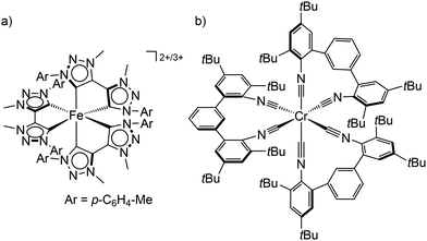 | ||
| Scheme 1 (a) Structure of the low-spin iron(II) and iron(III) complexes [Fe(btz)3]2+/3+ and (b) the tris(diisocyanide)chromium(0) complex Cr(CNtBuAr3NC)3. | ||
Using chelating isocyanide ligands in the tris(diisocyanide)chromium(0) complex Cr(CNtBuAr3NC)3 (Scheme 1b) with low-spin 3d6 electron configuration gives a large enough ligand field splitting Δo and consequently MC states at sufficiently high energy. Cr(CNtBuAr3NC)3 shows room temperature phosphorescence with an emission quantum yield Φem of ≈10−5 and a 3MLCT lifetime of 2.2 ns.28 This lifetime is sufficient to allow energy transfer reactions from the 3MLCT state to acceptors, which has been exploited in photon upconversion processes.28
In contrast to challenging 3d metal ions with weak ligand field splittings, 5d6 transition metal ions, such as Ir3+, possess a very large ligand field splitting due to the good M–L orbital overlap11 and the high oxidation state. Consequently, Ea is very large and kIC and knr′ become negligible (analogous to Fig. 4a). This excited state level ordering allows the successful incorporation of iridium(III) complexes in luminescent devices and their ubiquitous application in photocatalysis.4,7,8
3.2 3d10 complexes (copper(I))
Copper(I) complexes with closed-shell d10 GS configuration circumvent the problem of efficient non-radiative deactivation of MLCT states via low-lying MC states, as generally observed for 3d6 iron(II) complexes and other 3d metal ions with d1–d9 electron configuration.11 Together with pyridine or polypyridine ligands, low-energy MLCT states are available for luminescence. Especially the huge class of pseudotetrahedral diimine copper(I) complexes, e.g. [Cu(phenR2)2]+ with 2,9-disubstituted 1,10-phenanthroline ligands (R = H, Me, nBu, tBu, Ph,…), and heteroleptic complexes, play a dominant role in copper(I) photochemistry (Fig. 5).29–31 In fact, deactivation via MC states is absent, yet other non-radiative decay pathways come into play, especially the excited state flattening distortion (Fig. 5).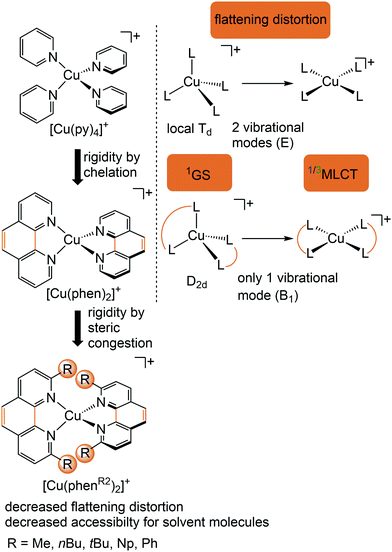 | ||
| Fig. 5 Luminescent [Cu(phenR2)2]+ complexes and concepts to minimize the flattening distortion in the MLCT states. | ||
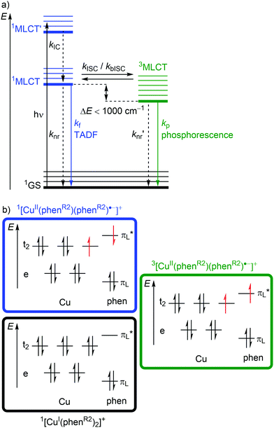
Excitation (λabs ≈ 400–500 nm) of [Cu(phenR2)2]+ populates a relatively high-lying 1MLCT’ state. After IC to the lowest energy 1MLCT state (kIC) and ISC (kISC), a 3MLCT state with a lifetime in the nanosecond to microsecond range30 is populated (Fig. 6a and 7b). This 3MLCT state displays phosphorescence at low temperatures (kp; Fig. 6a and 7b). A 1MLCT–3MLCT energy gap ΔE(1MLCT–3MLCT) smaller than 1000 cm−1, a long lifetime of the 3MLCT state and sufficient thermal energy available can enable thermally activated back intersystem crossing (bISC) leading to a Boltzmann distribution for the emissive 1/3MLCT state population (Fig. 6a).29,30 As fluorescence is a spin-allowed process, kf from the 1MLCT state is larger than kp from the 3MLCT state and a radiative process called thermally activated delayed fluorescence (TADF; kf; λem ≈ 600–800 nm) prevails at higher temperature.32,33
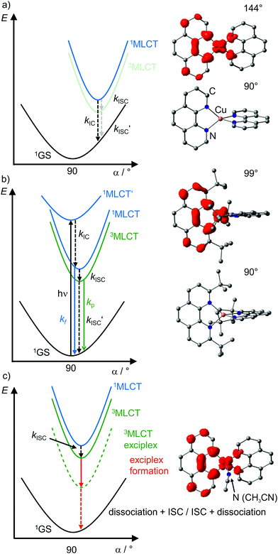 | ||
| Fig. 7 Schematic potential energy surface diagrams of [Cu(phenR2)2]+ complexes with relevant electronic states and photophysical processes (adapted from ref. 29 and 30) of (a) [Cu(phen)2]+, (b) [Cu(phentBu2)2]+ and (c) exciplex formation exemplified by the acetonitrile adduct of [Cu(phen)2]+ using DFT optimized geometries with spin densities of triplet states displayed in red (isosurface value: 0.005) and dihedral angles α indicated. (1MLCT’ state, electronic excitation and radiative processes omitted in (a) and (c) for clarity). | ||
Examination of the microstates of the 1/3MLCT states reveals that formally a reduced (poly)pyridyl ligand and a copper(II) ion with d9 configuration is formed (Fig. 6b). In contrast to the pseudotetrahedral GS with a copper(I) central ion, copper(II) ions prefer a square-planar coordination geometry. The non-symmetric population of the t2 orbitals (and of the degenerate ligand π*-orbitals) in the 1/3MLCT states leads to a (second order) Jahn–Teller distortion.29,34 The main structural distortion in the MLCT states corresponds to a flattening of the initial pseudotetrahedron in D2d symmetry to D2 symmetry (called flattening distortion; Fig. 5 and 7). As highly distorted excited states enable efficient non-radiative decay (Fig. 3b), the flattening competes with radiative processes (kf, kp) and consequently reduces luminescence quantum yields.29–33
In terms of conceptual ligand design, chelation should diminish the detrimental flattening distortion of CuI complexes in the MLCT states. Replacing four pyridine ligands in [Cu(py)4]+ by two rigid phen ligands in [Cu(phen)2]+ (Fig. 5) reduces the number of available flattening modes from two (Td: E vibrational mode) to one (D2d; B1 vibrational mode). Increasing the steric bulk of the phen ligand by 2,9-substitution in phenR2 further minimizes the flattening (Fig. 5). The dihedral angle α of the ligand planes describes the flattening of [Cu(phenR2)2]+ in the 1/3MLCT states as simplified reaction coordinate.29,30 In the 1GS, the phen ligands are orthogonal (α = 90°), while the 1/3MLCT states of [Cu(phen)2]+ are significantly stabilized at much larger angles (α = 144°) according to Density Functional Theory (DFT) calculations leading to horizontally displaced excited states (strong coupling limit, Fig. 7a). This horizontal displacement lowers the energy gap between MLCT states and GS and hence promotes non-radiative deactivation, according to the energy gap law14 (Fig. 3).29–31 Indeed, electronically excited [Cu(phen)2]+ evolves directly from the 1MLCT to the 1GS state by bypassing the 3MLCT state as lowest excited state, i.e. knr from the 1MLCT state outcompetes kISC (Fig. 7a).29 In the bulky [Cu(phentBu2)2]+ complex, the flattening is hindered due to the steric congestion and consequently, the 1/3MLCT states are rather nested with α = 99° (DFT calculations; weak coupling limit) and at relatively high energy (Fig. 7b). Both effects reduce the overall non-radiative rate constant knr and enable luminescence.
In addition to the increased non-radiative decay as detrimental pathway, the flattened geometry of the 3MLCT states renders the copper ion accessible for coordination of nucleophiles, e.g. solvent molecules or counter ions, to the positively charged metal center. The thus formed excited complexes (exciplexes) are non-luminescent as illustrated by the CH3CN adduct of [Cu(phen)2]+ (Fig. 7c).30 In fact, [Cu(phen)2](BPh4) is only luminescent in the solid state whereby flattening and exciplex formation is prevented.34 Two methyl groups in 2,9-positions of the phen ligands already suffice to obtain TADF for [Cu(phenMe2)2]+ in CH2Cl2 solution (ESI,‡ Table S2).31 Emission lifetime τem and quantum yield Φem of [Cu(phenR2)2]+ significantly increase with the steric demand of the substituents R, while knr decreases (ESI,‡ Table S2).31 The exciplex luminescence quenching depends on the donor strength and steric properties of the solvent and follows the series CH2Cl2 < THF < CHCl3 ≤ EtOH < MeOH < CH3CN < DMF.31 Additionally, anion coordination to the (formally) CuII ion in the MLCT states diminishes the luminescence in the series BPh4− ≤ PF6− < BF4− < ClO4− < NO3−.31
Applications of copper(I) complexes with optimized ligands are described for DSSCs, OLEDs, and for photocatalytic reactions.5,7,9,30,31 Due to the TADF phenomenon, optimized copper(I) complexes are capable to harvest singlet and triplet excitons for fluorescence emission, which is beneficial for OLED applications.7,32,33 Consequently, a maximum 100% efficiency can be expected from exciton spin statistics, similar to precious metal-based PHOLEDS.7,8
4. Complexes with long-lived LMCT states
4.1 4d0 complexes (zirconium(IV))
Detrimental MC states are absent for a closed shell d10 electronic configuration. Analogously, the “empty d shell” d0 configuration of a zirconium(IV) ion leads to the absence of parasitic MC states.11 Zirconium(IV) complexes – Zr(MePDP)2,35,36 Zr(RCNN)237 and ZrCl(MePMPMe)338 – with tri- and bidentate electron-rich π-donating pyridine (di)pyrrolide ligands feature long-lived CT states with mixed LMCT and intraligand charge transfer (ILCT) character (Fig. 8a, ESI,‡ Scheme S1).35–38 Under irradiation, all these complexes emit visible light at r.t. in solution (562–608 nm; Φ = 0.01–0.18) (ESI,‡ Table S3). This emission has been assigned to phosphorescence from 3(LMCT/ILCT) states (Fig. 8b).35–38 The lifetimes (τem ≈ 21–412 μs) of the 3(LMCT/ILCT) states are sufficiently long for applications of the zirconium complexes in bimolecular photoredox catalysis with visible light excitation (Fig. 8c, ESI,‡ Scheme S2).5,6,35–38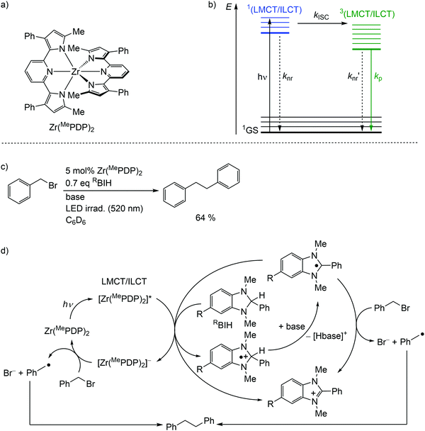 | ||
| Fig. 8 (a) Structure of the zirconium(IV) complex Zr(MePDP)2 and (b) Jablonski diagram, (c) application of Zr(MePDP)2 in photoredox catalysis and (d) proposed mechanism (adapted from ref. 36). | ||
Upon electronic excitation, a molecule becomes a stronger reductant and a stronger oxidant. The Rehm–Weller formalism estimates excited state redox potentials E1/2* from ground state redox potentials E1/2 and the one-electron potential E00 corresponding to the energy difference between ground and excited state at their zero vibrational levels (0–0 transition) as E1/2*(A+/A*) = E1/2(A+/A) − E00(A*/A) and E1/2*(A*/A−) = E1/2(A/A−) + E00(A*/A).14,17
For the present photocatalytic application of zirconium(IV) complexes with d0 electron configuration, only the reductive process E1/2*(A*/A−) is relevant (see below for reductive and oxidative quenching processes). The potentials of the [Zr]/[Zr]− redox couples of E1/2 ≈ −2.2 V dramatically increase for the [Zr]*/[Zr]− redox couples to ≈−0.1 V (vs. ferrocene) (ESI,‡ Table S3).35–38 Consequently, amines are competent to reduce these complexes in their 3(LMCT/ILCT) excited states. Indeed, photocatalytic redox reactions using the zirconium complexes are initiated via reductive quenching by MeBIH (1,3-dimethyl-2-phenyl-2,3-dihydro-1H-7-methylbenzo-[d]imidazole) or MeOBIH as reductants (Fig. 8c, ESI,‡ Scheme S2).35–38
The photoredox catalytic coupling of benzyl bromide BnBr with Zr(MePDP)2 has been investigated in more detail and the proposed mechanism is depicted in Fig. 8d.36 After LMCT/ILCT excitation and ISC to the triplet state, [Zr(MePDP)2]* is reductively quenched via single-electron transfer to RBIH, forming [RBIH]˙+ (Fig. 8d). The concomitantly formed strong reductant [Zr(MePDP)2]− reacts with BnBr, generating benzyl radicals [Bn]˙ and bromide.36 A second source for [Bn]˙ from BnBr stems from the reaction with [RBI]˙, generated by deprotonation of [RBIH]˙+. Alternatively, [RBI]˙ acts as a strong reductive quencher for [Zr(MePDP)2]*, forming [RBI]+ and [Zr(MePDP)2]−. Two benzyl radicals finally couple to give bibenzyl (Fig. 8d). In summary, the d0 electron configuration with electron-rich ligands enables long-lived high-energy excited states, which are competent in photoredox catalytic processes.
4.2 Low-spin 3d5 complexes (iron(III))
In low-spin d5 iron(III) complexes with a 2GS, very strong σ-donor ligands can increase the energy of the detrimental 4/6MC states, so that they are only weakly populated. Indeed, low-spin d5 iron(III) complexes with mesoionic carbene or anionic tripodal tris(carbene) ligands [Fe(btz)3]3+ and [Fe(phtmeimb)2]+ (phtmeimb−: phenyl[tris(3-methylimidazol-1-ylidene)]borate) as electron-rich, strong σ-donor ligands represent the first luminescent iron complexes (Scheme 1a and Fig. 9a).22,26,39,40 They emit in acetonitrile solution at r.t. from their 2LMCT states at λem = 600 and 655 nm with fluorescence quantum yields of Φem = 3 × 10⁻⁴ and 0.021 and with 2LMCT lifetimes of τ = 0.10 and 1.96 ns, respectively (Fig. 9b and c).39,40 Although the 4T1g and 6A1g MC states are still below the 2LMCT state, [Fe(btz)3]3+ shows fluorescence. Non-radiative decay occurs directly from the 2LMCT state or via the strongly Jahn–Teller distorted 4MC (4T1g) state after ISC, while the 6A1g state with long Fe–N bonds is bypassed (Fig. 9 and 10).39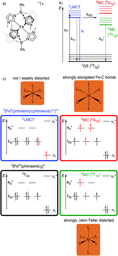 | ||
| Fig. 9 (a) Structure of [FeIII(phtmeimb)2]+, (b) energy-state diagram with (c) microstates of 2GS, 2LMCT and 4/6MC states. | ||
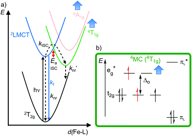 | ||
| Fig. 10 (a) Simplified potential energy surface diagram (adapted from ref. 40) with relevant electronic states and photophysical processes of [FeIII(phtmeimb)2]+. (b) Microstate of the detrimental 4MC (4T1g) state. The blue bold arrows indicate the interplay of MC state energies and energy of the eg* orbitals. | ||
Obviously, a significant activation barrier Ea for the 2LMCT → 4T1g ISC reduces kISC. On the other hand, fluorescence is a spin-allowed, fast process and the 2LMCT state is rather nested leading to large Franck–Condon factors for emission and consequently a large radiative rate constant kf (Fig. 10).39 The negatively charged tris(carbene) ligand phtmeimb− with its more rigid nearly perfect octahedral coordination geometry and good metal–ligand orbital overlap induces an even higher ligand field splitting than the neutral ligand btz.22,40 This significantly destabilizes the 4/6MC states of [Fe(phtmeimb)2]+ with respect to [Fe(btz)3]3+, further raising the activation barrier Ea and leading to a higher emission quantum yield and emission lifetime (Fig. 10).22,40 Since fluorescence is not quenched by triplet oxygen, the emission quantum yields of the iron(III) complexes are barely influenced by the presence of air. The fluorescence quantum yields and the excited state lifetimes of these iron(III) complexes are comparable to those of typical organic fluorophores.
[Fe(phtmeimb)2]+ in the 2LMCT excited state is a strong oxidant and reductant with excited state redox potentials of E1/2*([FeIII]*/[FeII]) = 1.0 V and E1/2*([FeIV]/[FeIII]*) = −1.9 V, respectively (E1/2([FeIII]/[FeII]) = −1.16 V, E1/2([FeIV]/[FeIII]) = 0.25 V, vs. ferrocene), according to the Rehm–Weller equation.40 The high excited state redox potentials and the sufficiently long lifetime of the 2LMCT state enable reductive quenching ([FeIII]* → [FeII]) with diphenylamine and oxidative quenching ([FeIII]* → [FeIV]) with the methylviologen dication after excitation at 465 nm.40 The exceptional characteristics of [Fe(phtmeimb)2]+ concerning excited state lifetime, emission quantum yield, excited state redox potentials and the insensitivity towards oxygen, exceed those of [Ru(bpy)3]2+ and render iron(III) complexes with strong donor ligands promising sensitizers for sustainable photochemical applications.40
5. Complexes with long-lived ligand field spin–flip states
5.1 3d3 complexes (chromium(III))
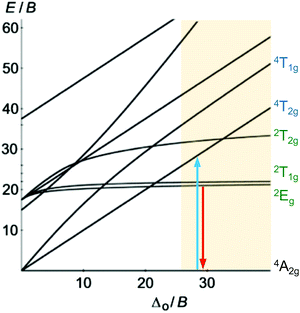
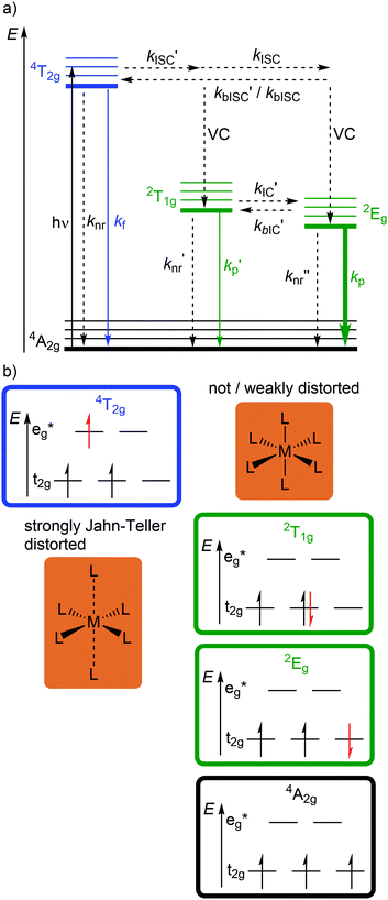
Beyond luminescent CT states (MLCT, LMCT), metal-centered states with small excited state distortion (nested states) can become emissive. As discussed above, interconfigurational transitions, e.g. between t2g and eg* orbitals lead to highly distorted excited MC states due to the population of antibonding orbitals. On the other hand, intraconfigurational transitions, e.g. a spin–flip within the t2g level, does not appreciably affect the electron density and consequently the nuclear coordinates. Hence, spin–flip states are typically nested states and thus long-lived with small non-radiative rate constants knr. This situation is in fact achieved in complexes with d3 electron configuration, e.g. chromium(III). In an octahedral ligand field, low-lying quartet (4T2g, 4T1g) and doublet (2Eg, 2T1g, 2T2g) ligand field excited states are above the 4A2g GS (Fig. 11).15,41 The interconfigurational 4T2g and 4T1g states with (t2g)2(eg*)1 electron configuration are strongly Jahn–Teller distorted and their energy depends on the ligand field strength Δo (Fig. 11 and 12). The energy of the intraconfigurational, non-distorted doublet states (2Eg, 2T1g, 2T2g) is essentially independent of Δo (Fig. 11 and 12b). For a sufficiently large ligand field strength (Δo ≫ 20 B), the 2Eg and 2T1g states become the excited states of lowest energy and bISC from the 2Eg to the 4T2g state is slow. A large enough gap ΔE(2Eg/4T2g) enables observation of sharp phosphorescence emission bands (Fig. 11 (red arrow)) after excitation into the spin-allowed 4T2g quartet state (Fig. 11 (blue arrow)) and ISC to the doublet states followed by VC (Fig. 12a).15,41 Furthermore, fast ISC to the doublet states and merely a transient population of the distorted 4T2g state prevents photosubstitution reactions in solution.41,42For the famous gemstone ruby (corundum (Al2O3) with Al3+ partially substituted by Cr3+), a sharp phosphorescence band is observed at λp = 694 nm.43 The required strong ligand field Δo for luminescent molecular systems is achieved for example with cyanide ligands or with bi- and tridentate N-donor ligands (ESI,‡ Table S4).41 These complexes emit in the red to near-infrared (NIR) region. The values for emission lifetime and emission quantum yield cover a large range. Among CrIII complexes with bidentate ligands, [Cr(phen)3]3+ possesses the highest values (ESI,‡ Table S4).
Beside the non-radiative deactivation of the 2Eg state via bISC to the 4T2g state, a trigonal distortion in the excited states can be responsible for higher rate constants knr as proposed for CrIII cage complexes.41 Upon symmetry lowering from Oh to D3h, the 4A2g GS and the 4T2g excited state in Oh symmetry mix giving a destabilized 4E′ (D3h) ground state and a stabilized 4E′′ (D3h) excited state. The stronger excited state distortion and the lower energy gap increase knr (Fig. 3). This trigonal distortion in tris(bidentate)chromium(III) complexes and the resulting high knr results in the rather low phosphorescence quantum yields (ESI,‡ Table S4).15,41 A trigonal distortion is absent for bis(tridentate) complexes, such as [Cr(tpy)2]3+ and [Cr(ddpd)2]3+ (ddpd: N,N′-dimethyl-N,N′-dipyridine-2-yl-pyridine-2,6-diamine) (Scheme 2).41
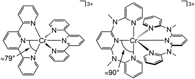
However, [Cr(tpy)2]3+ features a very low emission lifetime and emission quantum yield. This is due to a smaller ligand field strength Δo caused by the inefficient Cr–N orbital overlap, which is based on the small N–Cr–N bite angle of tpy (79°, Scheme 2). Consequently, the emissive doublet states and the distorted 4T2g state are closer in energy and bISC from the 2Eg to the 4T2g state (kbISC) followed by non-radiative relaxation (knr) dominates over phosphorescence (kp) (Fig. 12a). In contrast to the poorly emissive complex [Cr(tpy)2]3+, [Cr(ddpd)2]3+ emits at 775 nm after excitation at 420–435 nm (4T2g) with a record emission lifetime of τem = 898 μs and a record emission quantum yield of Φem = 0.11 for chromium(III) complexes at room temperature in solution (ESI,‡ Table S4).41,44
The tpy-like ddpd ligand expanded with electron-rich NMe groups forms six-membered chelate rings with the chromium ion. The N–Cr–N bite angle amounts to ≈90° leading to an almost ideal octahedral [CrN6] coordination geometry with good Cr–N orbital overlap and consequently a strong ligand field Δo (Scheme 2).41,44 The strong ligand field separates the 4T2g state from the emissive 2Eg and 2T1g states preventing bISC (Fig. 12a).42 The merely transient population of the distorted and dissociative 4T2g state without any re-population from the inert doublet states leads to an exceptional photostability of [Cr(ddpd)2]3+ over a wide pH range.44
Due to the low emission energy (775 nm; 12![[thin space (1/6-em)]](https://www.rsc.org/images/entities/char_2009.gif) 900 cm−1), a further pathway of non-radiative relaxation comes into play for these complexes. High energy oscillators with vibrational frequencies above 3000 cm−1 such as C–H, N–H, O–H enable the multiphonon relaxation as non-radiative process, as described by the so-called “inductive-resonant mechanism of non-radiative transitions” model.41,45 The electronic energy of an electronically excited state is thereby transferred to vibrational overtones (fourth and fifth overtone) of the oscillators. Removing such high-energy oscillators from the vicinity of the metal center shuts down this loss channel. For [Cr(ddpd)2]3+, only C–H modes are relevant. These can be removed by ligand deuteration. Indeed, employing the (partially) deuterated ligand [D9]-ddpd replaces the high energy C–H oscillators (≈3110 cm−1) by low energy C–D oscillators (≈2300 cm−1) and hence boosts the emission quantum yield of [Cr([D9]-ddpd)2]3+ to 0.30 and the lifetime to 2300 μs in CD3CN.41,45
900 cm−1), a further pathway of non-radiative relaxation comes into play for these complexes. High energy oscillators with vibrational frequencies above 3000 cm−1 such as C–H, N–H, O–H enable the multiphonon relaxation as non-radiative process, as described by the so-called “inductive-resonant mechanism of non-radiative transitions” model.41,45 The electronic energy of an electronically excited state is thereby transferred to vibrational overtones (fourth and fifth overtone) of the oscillators. Removing such high-energy oscillators from the vicinity of the metal center shuts down this loss channel. For [Cr(ddpd)2]3+, only C–H modes are relevant. These can be removed by ligand deuteration. Indeed, employing the (partially) deuterated ligand [D9]-ddpd replaces the high energy C–H oscillators (≈3110 cm−1) by low energy C–D oscillators (≈2300 cm−1) and hence boosts the emission quantum yield of [Cr([D9]-ddpd)2]3+ to 0.30 and the lifetime to 2300 μs in CD3CN.41,45
A special feature of the d3 electron configuration is the presence of two doublet states (2Eg, 2T1g) with similar energy (Fig. 11 and 12). In [Cr(ddpd)2]3+, the energy gap between these two states amounts to 650 cm−1 (ΔE(2Eg/2T1g) = 7.7 kJ mol−1). This is in the range of the thermal energy and hence IC′ and bIC′ between these states is fast and a Boltzmann distribution is established. As both states are only weakly distorted (nested states), both show emission. Consequently, dual emission occurs at 775 and 738 nm and the relative band intensities depend on the temperature. Due to the fast equilibration, the excited state lifetimes of both states are identical.41,44,46
With these unique properties (quantum yield, lifetime, dual sharp emission), [Cr(ddpd)2]3+ has been established as ratiometric optical thermometer requiring no external reference. These CrIII complexes can be employed molecularly dissolved in solution as well as embedded in biocompatible nanocarriers, working in the temperature range from 210 to 373 K.46,47 The actual temperature can be straightforwardly read out from the emission intensity ratio I738/I775 as a function of temperature from the linear Boltzmann relation between ln(I738/I775) and T−1 (Fig. 13).
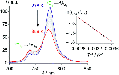 | ||
| Fig. 13 Variable temperature emission spectra of [Cr(ddpd)2]3+ in H2O from 278 to 358 K under air saturated conditions with Boltzmann plot ln(I738/I775vs. T−1) (adapted from ref. 46). | ||
The phosphorescence of [Cr(ddpd)2]3+ is efficiently quenched by energy transfer (EnT) to triplet oxygen 3O2, forming singlet oxygen 1O2 (Scheme 3, highlighted area).41,44 The bimolecular O2 quenching constant from a Stern–Volmer plot14 is estimated with kq = 1.77 × 10⁷ M−1 s−1 with the Stern–Volmer constant KSV = kd × τem = 1.59 × 10⁴M−1 for [Cr(ddpd)2](BF4)3 in H2O. Consequently, [Cr(ddpd)2]3+ can optically measure the actual oxygen concentration in solution (in combination with an inert reference emitter) enabling the application of [Cr(ddpd)2]3+ as oxygen sensor.47
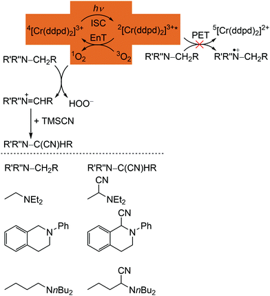 | ||
| Scheme 3 Proposed mechanism for the [Cr(ddpd)3]3+ sensitized photocyanation of amines with TMSCN via1O2 (energy transfer (EnT) step highlighted) with substrates and cyanation products (adapted from ref. 42). | ||
The quantum yields of [Cr(ddpd)]3+ for 1O2 formation in DMF and CH3CN are with Φ(1O2) = 0.61 sufficiently high for the application in organic synthesis using 1O2 as reagent.41,42 Consequently, [Cr(ddpd)2]3+ has been utilized as sensitizer for singlet oxygen formation and the generated 1O2 enables a subsequent α-cyanation of aliphatic amines with Me3SiCN (TMSCN) (Scheme 3).41,42 The conceivable side reaction of reductive quenching and amine oxidation is less likely due to the rather low excited state redox potential of the doublet states (E1/2([CrIII]*/[CrII]) = 0.49 V vs. ferrocene) according to the Rehm–Weller formalism (see above).42,44
Further applications of [Cr(ddpd)2]3+ as a molecular pressure sensor in solution and in the solid state,48 as potential photosensitizer in photodynamic therapy,49 and as emitter for circularly polarized luminescence (CPL)50 are currently emerging.
6. Conclusions
In order to replace limited fossil energy sources by sustainable sources such as sunlight, both the energy source and the required material utilization have to be considered for the overall sustainability. The resources for the production of devices for energy conversion, storage, etc. have to be reappraised with respect to sustainability. For an eco-friendly, resource-efficient and sustainable photochemistry with transition metal complexes it is mandatory to substitute precious and rare-Earth metal ions by Earth-abundant elements, e.g. 3d (and certain 4d) transition metal ions. Different strategies tackle the challenge to overcome the dominant non-radiative processes, which typically prevail in first row transition metal complexes.The interplay of “structure/bonding/states” for designing the photophysical landscape of photoactive transition metal complexes emerged as conceptual objective.
Most 3d complexes are still lacking the extraordinary photophysical and photochemical properties of their heavier precious metal counterparts. Yet, first successful design strategies have led to exciting and promising applications of complexes with Earth-abundant metal ions in DSSCs, OLEDs, sensors and as photocatalysts. Still, the photophysics and photochemistry of complexes with Earth-abundant transition metal ions offer a challenging playground for creative researchers to enable sustainable applications in the future.
List of relevant abbreviations
| n GS | Ground state with spin multiplicity n |
| n MC | Metal-centered/ligand field state |
| n LMCT | Ligand-to-metal charge transfer state |
| n MLCT | Metal-to-ligand charge transfer state |
| n ILCT | Intraligand charge transfer state |
| n LC | Ligand-centered state |
| IC | Internal conversion |
| ISC | Intersystem crossing |
| bISC | Back intersystem crossing |
| MECP | Minimum energy crossing point |
| VC | Vibrational cooling |
| NR | Non-radiative decay |
| TADF | Thermally activated delayed fluorescence |
| E a | Activation energy |
| k f | Rate constant for fluorescence |
| k p | Rate constant for phosphorescence |
| k nr | Rate constant for non-radiative process |
| Exciplex | Excited complex |
| NIR | Near-infrared |
Conflicts of interest
There are no conflicts to declare.Acknowledgements
Parts of this research were conducted using the supercomputer Mogon and/or advisory services offered by Johannes Gutenberg University Mainz (http://hpc.uni-mainz.de), which is a member of the AHRP (Alliance for High Performance Computing in Rhineland Palatinate, http://www.ahrp.info) and the Gauss Alliance e.V. The authors gratefully acknowledge the computing time granted on the supercomputer Mogon at Johannes Gutenberg University Mainz (http://hpc.uni-mainz.de).Notes and references
- N. Armaroli and V. Balzani, Chem. – Asian J., 2011, 6, 768–784 CrossRef CAS.
- S. Zhang, X. Yang, Y. Numata and L. Han, Energy Environ. Sci., 2013, 6, 1443–1464 RSC.
- D. M. Arias-Rotondo and J. K. McCusker, Chem. Soc. Rev., 2016, 45, 5803–5820 RSC.
- L. Marzo, S. K. Pagire, O. Reiser and B. König, Angew. Chem., Int. Ed., 2018, 57, 10034–10072 CrossRef CAS PubMed.
- C. B. Larsen and O. S. Wenger, Chem. – Eur. J., 2018, 24, 2039–2058 CrossRef CAS PubMed.
- B. M. Hockin, C. Li, N. Robertson and E. Zysman-Colman, Catal. Sci. Technol., 2019, 9, 889–915 RSC.
- H. Yersin, A. F. Rausch, R. Czerwieniec, T. Hofbeck and T. Fischer, Coord. Chem. Rev., 2011, 255, 2622–2652 CrossRef CAS.
- H. Xu, R. Chen, Q. Sun, W. Lai, Q. Su, W. Huang and X. Liu, Chem. Soc. Rev., 2014, 43, 3259–3302 RSC.
- C. Bizzarri, E. Spuling, D. M. Knoll, D. Volz and S. Bräse, Coord. Chem. Rev., 2018, 373, 49–82 CrossRef CAS.
- R. M. Izatt, S. R. Izatt, R. L. Bruening, N. E. Izatt and B. A. Moyer, Chem. Soc. Rev., 2014, 43, 2451–2475 RSC.
- J. K. McCusker, Science, 2019, 363, 484–488 CrossRef CAS PubMed.
- V. Balzani and S. Campagna, Photochemistry and Photophysics of Coordination Compounds I, Springer Berlin Heidelberg, Berlin, Heidelberg, 2007, vol. 280 Search PubMed.
- V. Balzani and S. Campagna, Photochemistry and Photophysics of Coordination Compounds II, Springer Berlin Heidelberg, Berlin, Heidelberg, 2007, vol. 281 Search PubMed.
- V. Balzani, P. Ceroni and A. Juris, Photochemistry and photophysics. Concepts, research, applications, Wiley-VCH, Weinheim, 1st edn, 2014 Search PubMed.
- P. S. Wagenknecht and P. C. Ford, Coord. Chem. Rev., 2011, 255, 591–616 CrossRef CAS.
- P. C. Ford, Chem. Sci., 2016, 7, 2964–2986 RSC.
- V. Balzani, G. Bergamini, S. Campagna and F. Puntoriero, in Photochemistry and Photophysics of Coordination Compounds I, ed. V. Balzani and S. Campagna, Springer Berlin Heidelberg, Berlin, Heidelberg, 2007, vol. 280, pp. 1–36 Search PubMed.
- H. Ishida, S. Tobita, Y. Hasegawa, R. Katoh and K. Nozaki, Coord. Chem. Rev., 2010, 254, 2449–2458 CrossRef CAS.
- Q. Sun, S. Mosquera-Vazquez, Y. Suffren, J. Hankache, N. Amstutz, L. M. Lawson Daku, E. Vauthey and A. Hauser, Coord. Chem. Rev., 2015, 282–283, 87–99 CrossRef CAS.
- A. Soupart, I. M. Dixon, F. Alary and J.-L. Heully, Theor. Chem. Acc., 2018, 137, 37 Search PubMed.
- A. Amini, A. Harriman and A. Mayeux, Phys. Chem. Chem. Phys., 2004, 6, 1157–1164 RSC.
- O. S. Wenger, Chem. – Eur. J., 2019, 25, 6043–6052 CrossRef CAS PubMed.
- O. S. Wenger, J. Am. Chem. Soc., 2018, 140, 13522–13533 CrossRef CAS PubMed.
- A. K. C. Mengel, C. Förster, A. Breivogel, K. Mack, J. R. Ochsmann, F. Laquai, V. Ksenofontov and K. Heinze, Chem. – Eur. J., 2015, 21, 704–714 CrossRef CAS PubMed.
- P. Chábera, K. S. Kjaer, O. Prakash, A. Honarfar, Y. Liu, L. A. Fredin, T. C. B. Harlang, S. Lidin, J. Uhlig, V. Sundström, R. Lomoth, P. Persson and K. Wärnmark, J. Phys. Chem. Lett., 2018, 9, 459–463 CrossRef PubMed.
- B. Sarkar and L. Suntrup, Angew. Chem., Int. Ed., 2017, 56, 8938–8940 CrossRef CAS PubMed.
- T. Duchanois, L. Liu, M. Pastore, A. Monari, C. Cebrián, Y. Trolez, M. Darari, K. Magra, A. Francés-Monerris, E. Domenichini, M. Beley, X. Assfeld, S. Haacke and P. C. Gros, Inorganics, 2018, 6, 63 CrossRef.
- L. A. Büldt, X. Guo, R. Vogel, A. Prescimone and O. S. Wenger, J. Am. Chem. Soc., 2017, 139, 985–992 CrossRef PubMed.
- M. Iwamura, S. Takeuchi and T. Tahara, Acc. Chem. Res., 2015, 48, 782–791 CrossRef CAS PubMed.
- M. W. Mara, K. A. Fransted and L. X. Chen, Coord. Chem. Rev., 2015, 282-283, 2–18 CrossRef CAS.
- Y. Zhang, M. Schulz, M. Wächtler, M. Karnahl and B. Dietzek, Coord. Chem. Rev., 2018, 356, 127–146 CrossRef CAS.
- R. Czerwieniec, M. J. Leitl, H. H. H. Homeier and H. Yersin, Coord. Chem. Rev., 2016, 325, 2–28 CrossRef CAS.
- H. Yersin, R. Czerwieniec, M. Z. Shafikov and A. F. Suleymanova, ChemPhysChem, 2017, 18, 3508–3535 CrossRef CAS PubMed.
- C. T. Cunningham, J. J. Moore, K. L. H. Cunningham, P. E. Fanwick and D. R. McMillin, Inorg. Chem., 2000, 39, 3638–3644 CrossRef CAS PubMed.
- Y. Zhang, J. L. Petersen and C. Milsmann, J. Am. Chem. Soc., 2016, 138, 13115–13118 CrossRef CAS PubMed.
- Y. Zhang, T. S. Lee, J. L. Petersen and C. Milsmann, J. Am. Chem. Soc., 2018, 140, 5934–5947 CrossRef CAS PubMed.
- Y. Zhang, J. L. Petersen and C. Milsmann, Organometallics, 2018, 37, 4488–4499 CrossRef CAS.
- Y. Zhang, N. G. Akhmedov, J. L. Petersen and C. Milsmann, Chem. – Eur. J., 2019, 25, 3042–3052 CAS.
- P. Chábera, Y. Liu, O. Prakash, E. Thyrhaug, A. E. Nahhas, A. Honarfar, S. Essén, L. A. Fredin, T. C. B. Harlang, K. S. Kjær, K. Handrup, F. Ericson, H. Tatsuno, K. Morgan, J. Schnadt, L. Häggström, T. Ericsson, A. Sobkowiak, S. Lidin, P. Huang, S. Styring, J. Uhlig, J. Bendix, R. Lomoth, V. Sundström, P. Persson and K. Wärnmark, Nature, 2017, 543, 695–699 CrossRef PubMed.
- K. S. Kjær, N. Kaul, O. Prakash, P. Chábera, N. W. Rosemann, A. Honarfar, O. Gordivska, L. A. Fredin, K.-E. Bergquist, L. Häggström, T. Ericsson, L. Lindh, A. Yartsev, S. Styring, P. Huang, J. Uhlig, J. Bendix, D. Strand, V. Sundström, P. Persson, R. Lomoth and K. Wärnmark, Science, 2019, 363, 249–253 CrossRef PubMed.
- S. Otto, M. Dorn, C. Förster, M. Bauer, M. Seitz and K. Heinze, Coord. Chem. Rev., 2018, 359, 102–111 CrossRef CAS.
- S. Otto, A. M. Nauth, E. Ermilov, N. Scholz, A. Friedrich, U. Resch-Genger, S. Lochbrunner, T. Opatz and K. Heinze, ChemPhotoChem, 2017, 1, 344–349 CrossRef CAS.
- C. Degli Esposti and L. Bizzocchi, J. Chem. Educ., 2007, 84, 1316 CrossRef CAS.
- S. Otto, M. Grabolle, C. Förster, C. Kreitner, U. Resch-Genger and K. Heinze, Angew. Chem., Int. Ed., 2015, 54, 11572–11576 CrossRef CAS PubMed.
- C. Wang, S. Otto, M. Dorn, E. Kreidt, J. Lebon, L. Sršan, P. Di Martino-Fumo, M. Gerhards, U. Resch-Genger, M. Seitz and K. Heinze, Angew. Chem., Int. Ed., 2018, 57, 1112–1116 CrossRef CAS PubMed.
- S. Otto, N. Scholz, T. Behnke, U. Resch-Genger and K. Heinze, Chem. – Eur. J., 2017, 23, 12131–12135 CrossRef CAS PubMed.
- C. Wang, S. Otto, M. Dorn, K. Heinze and U. Resch-Genger, Anal. Chem., 2019, 91, 2337–2344 CrossRef CAS PubMed.
- S. Otto, J. P. Harris, K. Heinze and C. Reber, Angew. Chem., Int. Ed., 2018, 57, 11069–11073 CrossRef CAS PubMed.
- U. Basu, S. Otto, K. Heinze and G. Gasser, Eur. J. Inorg. Chem., 2019, 37–41 CrossRef CAS.
- C. Dee, F. Zinna, W. R. Kitzmann, G. Pescitelli, K. Heinze, L. Di Bari and M. Seitz, Chem. Commun., 2019, 55, 13078–13081 RSC.
Footnotes |
| † This tutorial review focuses on mononuclear photoactive complexes. In particular, for copper(I), several oligonuclear photoactive systems are known. Exemplary literature reviews are collected in the ESI.‡ |
| ‡ Electronic supplementary information (ESI) available: Supplementary tables, schemes and details to DFT calculations. See DOI: 10.1039/c9cs00573k |
| This journal is © The Royal Society of Chemistry 2020 |


