 Open Access Article
Creative Commons Attribution 3.0 Unported Licence
A low-crystalline ruthenium nano-layer supported on praseodymium oxide as an active catalyst for ammonia synthesis†
Katsutoshi
Sato
*ab,
Kazuya
Imamura‡
b,
Yukiko
Kawano
b,
Shin-ichiro
Miyahara
a,
Tomokazu
Yamamoto
c,
Syo
Matsumura
c and
Katsutoshi
Nagaoka
*b
aElements Strategy Initiative for Catalysts and Batteries, Kyoto University, 1-30 Goryo-Ohara, Nishikyo-ku, Kyoto 615-8245, Japan
bDepartment of Applied Chemistry, Faculty of Engineering, Oita University, 700 Dannoharu, Oita 870-1192, Japan. E-mail: nagaoka@oita-u.ac.jp
cDepartment of Applied Quantum Physics and Nuclear Engineering, Kyushu University, 744 Motooka, Nishi-ku, Fukuoka 819-0395, Japan
First published on 19th September 2016
Abstract
Ammonia is a crucial chemical feedstock for fertilizer production and is a potential energy carrier. However, the current method of synthesizing ammonia, the Haber–Bosch process, consumes a great deal of energy. To reduce energy consumption, a process and a substance that can catalyze ammonia synthesis under mild conditions (low temperature and low pressure) are strongly needed. Here we show that Ru/Pr2O3 without any dopant catalyzes ammonia synthesis under mild conditions at 1.8 times the rates reported with other highly active catalysts. Scanning transmission electron micrograph observations and energy dispersive X-ray analyses revealed the formation of low-crystalline nano-layers of ruthenium on the surface of Pr2O3. Furthermore, CO2 temperature-programmed desorption revealed that the catalyst was strongly basic. These unique structural and electronic characteristics are considered to synergistically accelerate the rate-determining step of NH3 synthesis, cleavage of the N![[triple bond, length as m-dash]](https://www.rsc.org/images/entities/char_e002.gif) N bond. We expect that the use of this catalyst will be a starting point for achieving efficient ammonia synthesis.
N bond. We expect that the use of this catalyst will be a starting point for achieving efficient ammonia synthesis.
Introduction
Ammonia is one of the most important feedstocks in the modern chemical industry. Globally, >80% of ammonia produced is used to produce fertilizer, which is essential for growing crops.1 In addition, ammonia has recently attracted attention as a carrier of energy and hydrogen.2–5 Ammonia is produced by combining atmospheric N2 with hydrogen produced by renewable energy. The ammonia is liquefied and transported to where it is used to generate power in engines or electricity in fuel cells. Ammonia is being considered as a carrier of energy and hydrogen because, (1) it has a high energy density (12.8 GJ m−3) and (2) a high hydrogen content (17.6 wt%), and (3) carbon dioxide is not released when hydrogen is produced by ammonia decomposition.2 If ammonia can be produced efficiently from renewable energy, it can contribute to the solution of global problems related to energy and food production.Currently, most ammonia is synthesized via the Haber–Bosch process.6–8 This process is a major consumer of energy, accounting for about 1% of global energy consumption. In this process, about 60% of consumed energy is recovered and saved in ammonia as enthalpy. However, the remaining energy is lost, mainly during the production of hydrogen from natural gas, ammonia synthesis, and gas separation. Because ammonia synthesis is carried out at very high temperatures (>450 °C) and high pressures (>20 MPa), a major goal is the reduction of the high amount of energy used in this process.9 Curbing global energy consumption requires, inter alia, a catalyst that is able to produce ammonia at much lower temperatures and pressures than required for the iron-based catalysts used in the Haber–Bosch process.10–12
Ruthenium is a possible catalyst for ammonia synthesis because of its higher activity at low pressure and temperature compared to that of iron-based catalysts. The rate-determining step in NH3 synthesis is cleavage of the N![[triple bond, length as m-dash]](https://www.rsc.org/images/entities/char_e002.gif) N bond of N2, because the bond energy is very high (945 kJ mol−1).13,14 It has been reported that modification of the morphology of the Ru surface (“structural modification”) and of the Ru electronic states (“electronic modification”) are effective ways to accelerate the rate-determining step and thus enhance the ammonia-synthesis activity of the Ru catalyst.15,16 In the case of structural modification, the unusual unsaturated B5-type site of Ru has been proven to be highly active.17–19 The B5-type site consists of five Ru atoms: two at step edges and three on the lower terrace. The five Ru atoms are all associated with the transition state of adsorbed N2, which results in weakening of the N
N bond of N2, because the bond energy is very high (945 kJ mol−1).13,14 It has been reported that modification of the morphology of the Ru surface (“structural modification”) and of the Ru electronic states (“electronic modification”) are effective ways to accelerate the rate-determining step and thus enhance the ammonia-synthesis activity of the Ru catalyst.15,16 In the case of structural modification, the unusual unsaturated B5-type site of Ru has been proven to be highly active.17–19 The B5-type site consists of five Ru atoms: two at step edges and three on the lower terrace. The five Ru atoms are all associated with the transition state of adsorbed N2, which results in weakening of the N![[triple bond, length as m-dash]](https://www.rsc.org/images/entities/char_e002.gif) N bond.17 Adjusting the Ru particle size (e.g., to 5 nm when Ru particles are spherical) and changing the shape of Ru particles create an abundance of B5-type sites.18,20,21 In the case of electronic modification, the use of basic supports and the addition of a strong basic promoter to Ru catalysts have enhanced ammonia synthesis activity dramatically.15,16 The mechanism involves the transfer of electrons to the Ru metal from the basic components. Transfer of electrons from Ru to the antibonding π-orbitals of N2 then results in weakening of the N
N bond.17 Adjusting the Ru particle size (e.g., to 5 nm when Ru particles are spherical) and changing the shape of Ru particles create an abundance of B5-type sites.18,20,21 In the case of electronic modification, the use of basic supports and the addition of a strong basic promoter to Ru catalysts have enhanced ammonia synthesis activity dramatically.15,16 The mechanism involves the transfer of electrons to the Ru metal from the basic components. Transfer of electrons from Ru to the antibonding π-orbitals of N2 then results in weakening of the N![[triple bond, length as m-dash]](https://www.rsc.org/images/entities/char_e002.gif) N bond and promotion of N
N bond and promotion of N![[triple bond, length as m-dash]](https://www.rsc.org/images/entities/char_e002.gif) N cleavage.22 Weakening of the N
N cleavage.22 Weakening of the N![[triple bond, length as m-dash]](https://www.rsc.org/images/entities/char_e002.gif) N bond by doping with strong basic oxides has been confirmed by observation of the N
N bond by doping with strong basic oxides has been confirmed by observation of the N![[triple bond, length as m-dash]](https://www.rsc.org/images/entities/char_e002.gif) N stretching frequency with infrared spectroscopy (IR); the most effective promoter has been reported to be Cs2O.23,24 In fact, most of the highly active Ru catalysts contain Cs2O as a promoter.10,15,25,26 However, CsOH, which may be produced in the presence of an H2O impurity in the reactant, has a low melting point (272 °C) and may move on the surface of the catalyst particles or vaporize under the reaction conditions, the eventual result being degradation of the catalyst.27 On the other hand, BaO is also reported as an effective promoter and Ba–Ru/activated carbon (Ba–Ru/AC) has been used in commercial industrial processes.28 Recently, Horiuchi et al. reported that Ru/BaTiO3 and Ba–Ru/MgO show comparable high activity to Cs–Ru/MgO.26 Notably, Ru-loaded electride [Ca24Al28O64]4+(e−)4 (Ru/C12A7:e−), which is a new class of Ru catalyst supported on a non-oxide, shows high NH3-synthesis activity without any dopant.10,29,30 This high activity has been attributed to the high electron-donating power of the electride.
N stretching frequency with infrared spectroscopy (IR); the most effective promoter has been reported to be Cs2O.23,24 In fact, most of the highly active Ru catalysts contain Cs2O as a promoter.10,15,25,26 However, CsOH, which may be produced in the presence of an H2O impurity in the reactant, has a low melting point (272 °C) and may move on the surface of the catalyst particles or vaporize under the reaction conditions, the eventual result being degradation of the catalyst.27 On the other hand, BaO is also reported as an effective promoter and Ba–Ru/activated carbon (Ba–Ru/AC) has been used in commercial industrial processes.28 Recently, Horiuchi et al. reported that Ru/BaTiO3 and Ba–Ru/MgO show comparable high activity to Cs–Ru/MgO.26 Notably, Ru-loaded electride [Ca24Al28O64]4+(e−)4 (Ru/C12A7:e−), which is a new class of Ru catalyst supported on a non-oxide, shows high NH3-synthesis activity without any dopant.10,29,30 This high activity has been attributed to the high electron-donating power of the electride.
We show here that a praseodymium oxide-supported Ru catalyst (Ru/Pr2O3) without any dopant exhibits unparalleled NH3 synthesis ability compared with highly active catalysts reported previously. The loading of Ru on the support was characterized by an unusual morphology of low-crystalline nano-layers, and the basicity of the catalyst was very high. We show that the combination of these features facilitated the activation of N2.
Results and discussion
NH3-synthesis activities of supported Ru-catalysts
Fig. 1 compares the NH3-synthesis activity of the Ru/Pr2O3 catalyst with that of other supported Ru catalysts under the same reaction conditions. Ba–Ru/activated carbon (Ba–Ru/AC) has been used in industrial processes;28 Cs–Ru/MgO is one of the most active Ru catalysts in NH3 synthesis;25,31 and Ru/C12A7:e− has attracted attention as a new active NH3-synthesis catalyst.10–12 At 400 °C and 0.1 MPa (Fig. 1a), Ru/Pr2O3 and Cs–Ru/MgO gave NH3 yields near the thermodynamic equilibrium (0.88%). Both the yields and NH3 production rates were higher than those achieved with the Ru/C12A7:e− and Ba–Ru/AC catalysts. In the industrial process, it is important to obtain high one-pass NH3 yields to avoid the high energy usage required for gas separation. Furthermore, from the standpoint of thermodynamic regulation, NH3 synthesis is favored if the reaction is carried out under high pressure.9 We therefore measured the NH3-synthesis activity at 1.0 MPa (Fig. 1b), where the NH3 yield at the thermodynamic equilibrium increases to 7.9%. Note that 1.0 MPa is still much lower than the reaction pressure used for the Haber–Bosch process. With the increase in reaction pressure, the differences in the activities of the catalysts were more pronounced: the NH3 yield reached 4.8% and the rate of formation obtained over Ru/Pr2O3 reached 19![[thin space (1/6-em)]](https://www.rsc.org/images/entities/char_2009.gif) 000 μmol g−1 h−1, >1.8 times the values associated with other catalysts.
000 μmol g−1 h−1, >1.8 times the values associated with other catalysts.
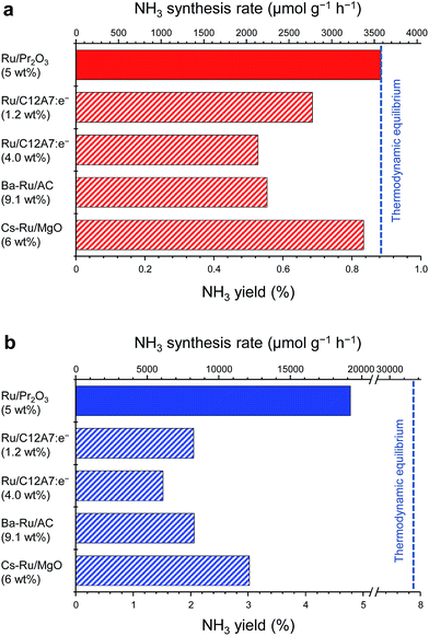 | ||
| Fig. 1 Catalytic performance of supported Ru catalysts for NH3 synthesis at (a) 0.1 MPa and (b) 1 MPa. Reaction conditions: catalyst, 0.2 g; reactant gas, H2/N2 = 3 with a flow rate of 60 mL min−1; reaction temperature, 400 °C. With the exception of Ru/Pr2O3, NH3 synthesis rates are reproduced from ref. 10. | ||
To understand why the rates of NH3 synthesis are so high when catalyzed by Ru/Pr2O3, we compared the characteristics of Ru/Pr2O3 with those of Ru/MgO and Ru/CeO2. All of the catalysts were loaded with 5 wt% Ru. Among the dopant-free simple oxide-supported Ru catalysts, Ru/MgO and Ru/CeO2 have shown relatively high NH3-synthesis activity,32 and CeO2 is a rare-earth oxide like Pr2O3. Fig. S2† shows in-situ X-ray diffraction patterns of the catalysts after activation in pure H2 at 400 °C. In the cases of Ru/MgO and Ru/CeO2, only diffraction patterns assigned to cubic-type MgO and CeO2 were obtained. In the case of Ru/Pr2O3, the diffraction peaks were attributed to rare earth C-type Pr2O3.33 On the other hand, the fact that no diffraction peaks of the Ru species were apparent in the patterns of the catalyst samples suggests that the crystallite size of the loaded Ru was too small to be detected. NH3-synthesis activities of the Ru catalysts were then measured at 0.9 MPa after reduction at 400 °C. Ru/Pr2O3 catalyzed NH3 synthesis at a much higher rate than that of Ru/MgO and Ru/CeO2 at all temperatures from 310 to 390 °C (Fig. 2). At 390 °C in particular, the NH3 synthesis rate of Ru/Pr2O3 was 15![[thin space (1/6-em)]](https://www.rsc.org/images/entities/char_2009.gif) 200 μmol g−1 h−1, much higher than that of Ru/CeO2 (7400 μmol g−1 h−1) and Ru/MgO (1500 μmol g−1 h−1). Furthermore, the long-term stability of the Ru/Pr2O3 catalyst at 390 °C under 0.9 MPa was evidenced by the fact that the rate of NH3 synthesis was stable for 50 h (Fig. S3†).
200 μmol g−1 h−1, much higher than that of Ru/CeO2 (7400 μmol g−1 h−1) and Ru/MgO (1500 μmol g−1 h−1). Furthermore, the long-term stability of the Ru/Pr2O3 catalyst at 390 °C under 0.9 MPa was evidenced by the fact that the rate of NH3 synthesis was stable for 50 h (Fig. S3†).
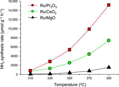 | ||
| Fig. 2 Rate of NH3 synthesis over supported Ru catalysts. Reaction conditions: catalyst, 0.2 g; reactant gas, H2/N2 = 3 with a flow rate of 60 mL min−1; pressure, 0.9 MPa. | ||
Specific surface areas of Ru/Pr2O3, Ru/CeO2, and Ru/MgO were 20.4, 33.5, and 46.4 m2 g−1, respectively (Table 1). There was no clear correlation between specific surface area and catalytic activity. Interestingly, the H/Ru ratio, a measure of Ru dispersion, was very low for Ru/Pr2O3 compared with that of the other catalysts. As a result, the turnover frequency of Ru/Pr2O3 was >3.5 times that of Ru/CeO2 and Ru/MgO. These results suggest that the high turnover frequency of Ru/Pr2O3 makes the excellent rate of synthesis of NH3 (activity per weight of catalyst) possible.
| Catalyst | Specific surface area (m2 g−1) | H/Rua | Turnover frequencyb (s−1) | Density of base sitesc (μmol m−2) |
|---|---|---|---|---|
| a Estimated by using H2 chemisorption capacity. b Calculated by using H/Ru value and NH3 yield at 390 °C under 0.9 MPa. c Estimated by using CO2-TPD. | ||||
| Ru/Pr2O3 | 20.4 | 0.17 | 0.050 | 4.4 |
| Ru/CeO2 | 33.5 | 0.29 | 0.014 | 2.3 |
| Ru/MgO | 46.4 | 0.3 | 0.003 | 2.2 |
Structural properties of Ru/Pr2O3
As the NH3-synthesis ability of a supported Ru catalyst is related to the morphology of the loaded Ru and the basicity of the support material, we used scanning transmission electron micrograph (STEM) observations and energy dispersive X-ray (EDX) analysis to investigate the morphology. Fig. 3 and S4† show high-angle annular dark-field (HAADF) images and EDX maps of Ru/Pr2O3 following treatment of the catalyst with H2 at 400 °C. Fig. S5 and S6† show analogous images and maps of Ru/CeO2 and Ru/MgO, respectively. A number of particles identified as Ru species by EDX were supported on MgO and CeO2, but were seldom observed over Pr2O3. However, the EDX map showed that Ru was dispersed over the entire Pr2O3 surface. In the reconstructed overlapping EDX images, the greenish edges of the catalyst particles indicated that the surfaces of the catalyst particles were covered by the Ru species. These results suggest that the state of Ru is completely different when it is loaded over Pr2O3versus MgO and CeO2. To further investigate the surface morphology, we made high-resolution STEM (HR-STEM) observations (Fig. 4, and see Fig. S7–S9†). On Ru/MgO and Ru/CeO2, the lattice fringes of the Ru species and the supports were clearly apparent. The d space of the Ru species was 0.21 nm, which is consistent with that of the (101) plane of metallic Ru. Mean diameters of the Ru particles were 1.8 ± 0.7 nm on Ru/MgO and 2.5 ± 0.8 nm on Ru/CeO2. In addition, the surface of the supports of these catalysts was smooth, and changes in the lattice fringe were clearly observed on the boundaries between Ru particles and supports (Fig. 4b and c, S8 and S9†). In contrast, on Ru/Pr2O3, the surface of Pr2O3 was covered by layers of Ru rather than by particles. The fact that the lattice fringes of most parts of the Ru layers were not apparent indicated that the crystallinity of the Ru layers was low. The thickness of the Ru layers was 0.5–3 nm, and Ru particles were sometimes included in the layers. Thus, we considered that the surface of Pr2O3 was covered mainly with low-crystalline Ru nano-layers.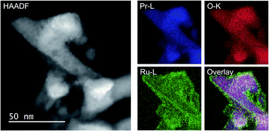 | ||
| Fig. 3 HAADF-STEM image, Pr-L, O-K, and Ru-L STEM-EDX maps, and reconstructed overlay image of Pr, O, and Ru for Ru/Pr2O3 after H2 reduction. | ||
To explain why the Ru on the Pr2O3 support possessed such a unique morphology, we analysed the X-ray diffraction patterns of the catalyst precursors of Ru/Pr2O3. As shown in Fig. S10,† the bare support [before impregnation with Ru3(CO)12] showed the structure of fluorite-type Pr6O11. However, after impregnation with Ru3(CO)12 in tetrahydrofuran (THF) and drying, the peaks assigned to Pr6O11 became smaller, and peaks attributed to Pr(OH)3 and PrOOH appeared. Furthermore, after heat treatment under a stream of Ar at 350 °C, only peaks corresponding to PrOOH were observed. At this point, the HAADF STEM and overlay of the EDX maps of Ru/Pr2O3 demonstrated that the surfaces of the catalyst particles were covered by Ru species (Fig. S11†). These results indicate that Ru3(CO)12 reacted with the O2− in Pr6O11 and Pr4+ was reduced to Pr3+, with the formation of CO2. The support then reacted with the H2O impurity in the THF, and after heat treatment in the Ar stream, Ru and PrOOH were formed. In brief, the results reveal that the high reactivity between Ru3(CO)12 and Pr6O11 prevented aggregation of Ru3(CO)12 with Ru3(CO)12 and contributed to the formation of the unique structure of the loaded Ru. The rough surface of the Pr2O3 and the fuzziness of the boundary between Ru and Pr2O3 in the HR-STEM image in Fig. 4a and S7† was probably due to the reaction between Ru3(CO)12 and Pr6O11. Furthermore, during H2 treatment, PrOOH was converted to Pr2O3 (Fig. S2†). During this process, part of the Ru included in the Ru layers was crystallized to form Ru particles, and thus Ru particles were sometimes observed in the Ru layers in the HR-STEM images (Fig. S7†). As shown in the HR-STEM images, the Ru species over Pr2O3 were arranged in a low-crystalline, nano-layered structure. In such a structure, unsaturated Ru atoms were not precisely arranged and formed step-and-terrace sites similar to a B5-type site. The unique surface morphology of Ru in Ru/Pr2O3 would promote N2 adsorption and subsequent cleavage of the N![[triple bond, length as m-dash]](https://www.rsc.org/images/entities/char_e002.gif) N bond.
N bond.
In addition, we carried out STEM-EDX observations of Ru/Pr2O3 after the long-term stability test shown in Fig. S3.† As shown in Fig. S12 and S13,† Pr2O3 was still covered with low-crystalline Ru nano-layers, as it was before reaction, and distinct changes of the structure were not observable. These results demonstrate the high durability of the unique surface structure of Ru/Pr2O3 under the conditions used for NH3 synthesis.
Basic properties of Ru/Pr2O3
We used CO2 temperature-programmed desorption (CO2-TPD) measurements of the catalysts (Fig. 5) to evaluate another crucial determinant of NH3-synthesis ability, the basicity of the support. To remove the contribution of the CO2 that remained on the surface even after H2 reduction, we subtracted the CO2-TPD profile without CO2 adsorption from that after CO2 adsorption (see Fig. S14† for original figures). CO2 desorption was observed at 50–680 °C on Ru/Pr2O3, 50–600 °C on Ru/CeO2, and 50–500 °C on Ru/MgO. CO2 desorption observed in the high temperature region (≥300 °C) was greatest on Ru/Pr2O3, intermediate on Ru/CeO2, and least on Ru/MgO. These results indicate that the basic sites on Ru/Pr2O3 are the strongest, and those on Ru/MgO are the weakest. We used the total amount of CO2 desorbed as a metric of basic density over the catalysts. Ru/Pr2O3 had the highest basic density, 4.4 μmol m−2, almost twice that of Ru/CeO2, 2.3 μmol m−2, and Ru/MgO, 2.2 μmol m−2. These results reveal that the surface basicity of Ru/Pr2O3 was much stronger than that of Ru/MgO and Ru/CeO2. This strong surface basicity results in the most effective electron donation to Ru and promotes N2 adsorption and subsequent cleavage of the N![[triple bond, length as m-dash]](https://www.rsc.org/images/entities/char_e002.gif) N bond. Furthermore, we can say that Pr2O3 is covered by islands of Ru nano-layers, which allow large amounts of CO2 to adsorb on the surface of uncovered Pr2O3. Note also that the CO2 desorption temperature and the total density of the basic sites were higher on Ru/CeO2 than on Ru/MgO. This difference accounts for the higher NH3-synthesis activity of Ru/CeO2 than that of Ru/MgO.
N bond. Furthermore, we can say that Pr2O3 is covered by islands of Ru nano-layers, which allow large amounts of CO2 to adsorb on the surface of uncovered Pr2O3. Note also that the CO2 desorption temperature and the total density of the basic sites were higher on Ru/CeO2 than on Ru/MgO. This difference accounts for the higher NH3-synthesis activity of Ru/CeO2 than that of Ru/MgO.
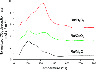 | ||
| Fig. 5 CO2-TPD profiles of supported Ru catalysts. Following H2 reduction at 400 °C, CO2 adsorption was carried out at 50 °C. These curves show the difference between the curves shown in Fig. S14† to remove the contribution of CO2 that remained on the surface of the catalysts even after H2 pre-treatment. | ||
Activation of N2 over Ru/Pr2O3
Finally, to understand the activation of N2 molecules over the Ru/Pr2O3 catalyst, we examined the states of the adsorbed N2 with FT-IR techniques. The IR spectra after the addition of N2 to Ru/MgO, Ru/CeO2, and Ru/Pr2O3 at room temperature are shown in Fig. 6. The IR spectrum of each catalyst shows a broad peak around 2350 to 2100 cm−1; such peaks are assignable to the stretching vibration mode of the N2 adsorbed with an end-on orientation on the Ru surface.21,23,24 Note that the peak absorbance of N2 adsorbed on Ru/Pr2O3 occurred at a lower frequency (2178 cm−1) than the corresponding peak absorbances on Ru/MgO (2210 cm−1) and Ru/CeO2 (2189 cm−1). In the spectrum of 15N2 adsorbed on Ru/Pr2O3, the peak absorbance was shifted to a lower frequency (2106 cm−1) compared to that on Ru/Pr2O3 (2178 cm−1), which is in good agreement with the frequency estimated from the isotope effect (2178 cm−1 × (14/15)1/2 = 2104 cm−1).23,24 These results suggest that these peaks are associated with the N2 on the Ru surfaces. The lower frequencies of the peak absorbances of N2 adsorbed on Ru/Pr2O3 compared to those of Ru/MgO and Ru/CeO2 indicate that the N![[triple bond, length as m-dash]](https://www.rsc.org/images/entities/char_e002.gif) N bond of N2 was further weakened over the low-crystalline Ru nano-layers on Pr2O3 relative to Ru nanoparticles on the other supports. We surmise that the morphology of the Ru surface and the basicity of the catalyst contributed synergistically to the weakening of the N
N bond of N2 was further weakened over the low-crystalline Ru nano-layers on Pr2O3 relative to Ru nanoparticles on the other supports. We surmise that the morphology of the Ru surface and the basicity of the catalyst contributed synergistically to the weakening of the N![[triple bond, length as m-dash]](https://www.rsc.org/images/entities/char_e002.gif) N bond and enhanced the catalytic activity for NH3 synthesis.
N bond and enhanced the catalytic activity for NH3 synthesis.
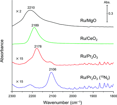 | ||
| Fig. 6 Difference infrared spectra of N2 molecules (before and after N2 adsorption) on supported Ru catalysts. Spectra were collected under 6 kPa of N2 (15N2 for Ru/Pr2O3) at 25 °C. | ||
Conclusions
In summary, we demonstrated that Ru/Pr2O3 without any dopant catalyzed a high rate of NH3 synthesis under mild reaction conditions (0.1–1.0 MPa). Characteristics of Ru/Pr2O3 include low-crystalline Ru nano-layers formed by the reaction between Ru3(CO)12 and Pr6O11 and strong basicity of Pr2O3. These characteristics are considered to synergistically accelerate the rate-determining step of ammonia synthesis: cleavage of the N![[triple bond, length as m-dash]](https://www.rsc.org/images/entities/char_e002.gif) N bond of N2. In addition, substitution of some of the praseodymium with another element without degrading its activity for NH3 synthesis is currently in progress, because Pr is an expensive element. The outcome of the research will appear in a coming contribution. We believe that our catalyst will facilitate the development of an effective method for synthesizing ammonia from renewable energy under environmentally benign conditions. Such a method can be expected to contribute to the solution of food and energy crises globally.
N bond of N2. In addition, substitution of some of the praseodymium with another element without degrading its activity for NH3 synthesis is currently in progress, because Pr is an expensive element. The outcome of the research will appear in a coming contribution. We believe that our catalyst will facilitate the development of an effective method for synthesizing ammonia from renewable energy under environmentally benign conditions. Such a method can be expected to contribute to the solution of food and energy crises globally.
Acknowledgements
This work was supported by CREST, Japan Agency of Science and Technology (JST). STEM/TEM observations were performed as part of a program conducted by the Advanced Characterization Nanotechnology Platform Japan, sponsored by the Ministry of Education, Culture, Sports, Science and Technology (MEXT), Japan. K. Sato thanks the Program for the Elements Strategy Initiative for Catalysts & Batteries (ESICB) commissioned by MEXT. T. Toriyama (Kyushu University) is acknowledged for assistance with STEM/TEM observations. The authors thank Mr Y. Wada, Ms. M. K. Nakao, and Mr T. Terasawa (Oita University) for assistance with sample preparation, catalytic activity tests, and characterization techniques. We acknowledge Prof. K. Shimizu (Hokkaido University) for fruitful discussions concerning IR analysis.Notes and references
- J. W. Erisman, M. A. Sutton, J. Galloway, Z. Klimont and W. Winiwarter, Nat. Geosci., 2008, 1, 636–639 CrossRef CAS.
- A. Klerke, C. H. Christensen, J. K. Nørskov and T. Vegge, J. Mater. Chem., 2008, 18, 2304–2310 RSC.
- R. Schlogl, ChemSusChem, 2010, 3, 209–222 CrossRef PubMed.
- F. Schüth, R. Palkovits, R. Schlögl and D. S. Su, Energy Environ. Sci., 2012, 5, 6278–6289 Search PubMed.
- J. W. Makepeace, T. J. Wood, H. M. A. Hunter, M. O. Jones and W. I. F. David, Chem. Sci., 2015, 6, 3805–3815 RSC.
- H. Bielawa, O. Hinrichsen, A. Birkner and M. Muhler, Angew. Chem., Int. Ed., 2001, 40, 1061–1063 CrossRef CAS.
- T. Kandemir, M. E. Schuster, A. Senyshyn, M. Behrens and R. Schlogl, Angew. Chem., Int. Ed., 2013, 52, 12723–12726 CrossRef CAS PubMed.
- S. Perathoner and G. Centi, ChemSusChem, 2014, 7, 1274–1282 CrossRef CAS PubMed.
- C. W. Hooper, Ammonia Synthesis: Commercial Practice, in Catalytic Ammonia Synthesis, Fundamentals and Practice, ed. J. R. Jennings, Springer, US, 1991, pp. 253–283 Search PubMed.
- M. Kitano, Y. Inoue, Y. Yamazaki, F. Hayashi, S. Kanbara, S. Matsuishi, T. Yokoyama, S. W. Kim, M. Hara and H. Hosono, Nat. Chem., 2012, 4, 934–940 CrossRef CAS PubMed.
- F. Hayashi, M. Kitano, T. Yokoyama, M. Hara and H. Hosono, ChemCatChem, 2014, 6, 1317–1323 CAS.
- Y. Inoue, M. Kitano, S.-W. Kim, T. Yokoyama, M. Hara and H. Hosono, ACS Catal., 2014, 4, 674–680 CrossRef CAS.
- S. Gambarotta and J. Scott, Angew. Chem., Int. Ed., 2004, 43, 5298–5308 CrossRef CAS PubMed.
- H. K. Chae, D. Y. Siberio-Perez, J. Kim, Y. Go, M. Eddaoudi, A. J. Matzger, M. O'Keeffe and O. M. Yaghi, Nature, 2004, 427, 523–527 CrossRef CAS PubMed.
- K. Aika, H. Hori and A. Ozaki, J. Catal., 1972, 27, 424–431 CrossRef CAS.
- K. Aika, M. Kumasaka, T. Oma, O. Kato, H. Matsuda, N. Watanabe, K. Yamazaki, A. Ozaki and T. Onishi, Appl. Catal., 1986, 28, 57–68 CrossRef CAS.
- S. Dahl, A. Logadottir, R. C. Egeberg, J. H. Larsen, I. Chorkendorff, E. Törnqvist and J. K. Nørskov, Phys. Rev. Lett., 1999, 83, 1814–1817 CrossRef.
- C. J. H. Jacobsen, S. Dahl, P. L. Hansen, E. Törnqvist, L. Jensen, H. Topsøe, D. V. Prip, P. B. Møenshaug and I. Chorkendorff, J. Mol. Catal. A: Chem., 2000, 163, 19–26 CrossRef CAS.
- S. Dahl, E. Tornqvist and I. Chorkendorff, J. Catal., 2000, 192, 381–390 CrossRef CAS.
- Z. Song, T. Cai, J. C. Hanson, J. A. Rodriguez and J. Hrbek, J. Am. Chem. Soc., 2004, 126, 8576–8584 CrossRef CAS PubMed.
- Z. You, K. Inazu, K. Aika and T. Baba, J. Catal., 2007, 251, 321–331 CrossRef CAS.
- K. Aika, A. Ohya, A. Ozaki, Y. Inoue and I. Yasumori, J. Catal., 1985, 92, 305–311 CrossRef CAS.
- J. Kubota and K. Aika, J. Chem. Soc., Chem. Commun., 1991, 1544 RSC.
- J. Kubota and K. Aika, J. Phys. Chem., 1994, 98, 11293–11300 CrossRef CAS.
- K. Aika, T. Takano and S. Murata, J. Catal., 1992, 136, 126–140 CrossRef CAS.
- Y. Horiuchi, G. Kamei, M. Saito and M. Matsuoka, Chem. Lett., 2013, 42, 1282–1284 CrossRef CAS.
- J. G. van Ommen, W. J. Bolink, J. Prasad and P. Mars, J. Catal., 1975, 38, 120–127 CrossRef CAS.
- D. E. Brown, T. Edmonds, R. W. Joyner, J. J. McCarroll and S. R. Tennison, Catal. Lett., 2014, 144, 545–552 CrossRef CAS.
- M. Kitano, Y. Inoue, H. Ishikawa, K. Yamagata, T. Nakao, T. Tada, S. Matsuishi, T. Yokoyama, M. Hara and H. Hosono, Chem. Sci., 2016, 7, 4036–4043 RSC.
- Y. Lu, J. Li, T. Tada, Y. Toda, S. Ueda, T. Yokoyama, M. Kitano and H. Hosono, J. Am. Chem. Soc., 2016, 138, 3970–3973 CrossRef CAS PubMed.
- F. Rosowski, A. Hornung, O. Hinrichsen, D. Herein, M. Muhler and G. Ertl, Appl. Catal., A, 1997, 151, 443–460 CrossRef CAS.
- Y. Niwa and K.-i. Aika, Chem. Lett., 1996, 25, 3–4 CrossRef.
- G. Adachi and N. Imanaka, Chem. Rev., 1998, 98, 1479–1514 CrossRef CAS.
Footnotes |
| † Electronic supplementary information (ESI) available: Detailed procedures for each method, catalytic performance, STEM-EDX images, detailed characterization. See DOI: 10.1039/c6sc02382g |
| ‡ Present address: Research Laboratory of Hydrothermal Chemistry, Faculty of Science, Kochi University. 2-5-1 Akebono-cho, Kochi 780-8520, Japan. |
| This journal is © The Royal Society of Chemistry 2017 |

