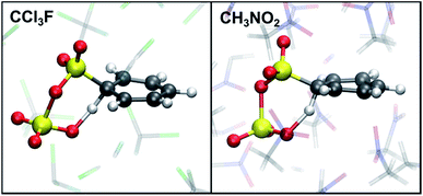
 Open Access Article
Aromatic sulfonation with sulfur trioxide: mechanism and kinetic model†
Samuel L. C.
Moors
*a,
Xavier
Deraet
a,
Guy
Van Assche
 b,
Paul
Geerlings
a and
Frank
De Proft
a
aEenheid Algemene Chemie (ALGC), Vrije Universiteit Brussel (VUB), Pleinlaan 2, 1050 Elsene, Brussels, Belgium. E-mail: samuel.moors@vub.ac.be
bPhysical Chemistry and Polymer Science (FYSC), Vrije Universiteit Brussel (VUB), Pleinlaan 2, 1050 Elsene, Brussels, Belgium
First published on 12th September 2016
Abstract
Electrophilic aromatic sulfonation of benzene with sulfur trioxide is studied with ab initio molecular dynamics simulations in gas phase, and in explicit noncomplexing (CCl3F) and complexing (CH3NO2) solvent models. We investigate different possible reaction pathways, the number of SO3 molecules participating in the reaction, and the influence of the solvent. Our simulations confirm the existence of a low-energy concerted pathway with formation of a cyclic transition state with two SO3 molecules. Based on the simulation results, we propose a sequence of elementary reaction steps and a kinetic model compatible with experimental data. Furthermore, a new alternative reaction pathway is proposed in complexing solvent, involving two SO3 and one CH3NO2.
Introduction
Aromatic sulfonation is a very important chemical transformation of organic compounds.1,2 It belongs to the well-known class of electrophilic aromatic substitution (SEAr) reactions alongside nitration, halogenation, acylation and alkylation. Sulfonation is a key reaction step in large industrial applications including pharmaceuticals, detergents, surfactants, dyes, and pesticides.3–5 The most commonly used sulfonating agents are sulfur trioxide (SO3), oleum, sulfuric acid and chlorosulfuric acid.6Traditionally, SEAr reactions are explained by a two-step SE2 or arenium ion mechanism.7 In the first and rate-determining step, an electrophile attacks the electron-rich aromatic ring to form a σ-complex or wheland or arenium ion intermediate, which is stabilized by mesomery. Aromaticity is restored in the second step by elimination of H+. Recently, alternative pathways to the arenium mechanism have been proposed by Schleyer and coworkers in various electrophilic aromatic substitution reactions8 including halogenation,9,10 nitration,11 and sulfonation.12 These studies highlight the diversity in reaction mechanisms for SEAr and their dependence on substrate and reaction conditions.
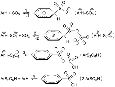
Based on kinetic experiments on chlorobenzene and 1,4-dichlorobenzene, Cerfontain and coworkers proposed a three-step kinetic scheme for the sulfonation of arenes with SO3 in aprotic solvents (Scheme 1).13–16 The first step is a reversible reaction wherein a σ-complex is formed between the arene and a SO3 molecule. In the second step a second SO3 reversibly binds to the first SO3. Finally, proton transfer from the arene to the second SO3 in the third step restores aromaticity and drives the reaction toward arenepyrosulfonic acid (ArS2O6H), which can be readily hydrolyzed in aqueous media. In apolar noncomplexing CCl3F solvent sulfonation kinetics are first order in SO3, and thus step 1 was thought to be rate-limiting.17 In contrast, in polar SO3-complexing18 CH3NO2 the rate is second order in SO3, and step 2 was taken as the rate-limiting step.17
If less than two equivalents of SO3 are used per mole arene, two sulfonation stages can be distinguished. A fast primary stage purportedly proceeds via the reaction steps 1–3 (Scheme 1). A much slower secondary stage was proposed to proceed through a reaction of arenepyrosulfonic acid with arene, forming two molecules of arenesulfonic acid (ArSO3H, step 4).13,19 This study, however, is focused on the primary sulfonation stage.
The mechanism proposed by Cerfontain and coworkers involving a σ-complex intermediate with one SO3 has been challenged by recent theoretical studies. Morley et al.20,21 performed quantum chemical calculations at the Hartree–Fock level on the sulfonation of toluene with SO3 in gas phase, and concluded that formation of a toluene–SO3 σ-complex was unlikely due to the high energy change required. Instead, they proposed the initial formation of a toluene⋯SO3⋯SO3 π-complex followed by a toluene–S2O6 σ-complex with almost the same energy, and a cyclic proton rearrangement yielding toluenepyrosulfonic acid.
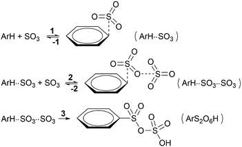
Schleyer and coworkers studied the sulfonation of several arenes with static density functional and SCS-MP2 calculations in implicit solvent.12 The sulfonation of benzene, 1,4-dichlorobenzene, toluene, and naphthalene, in gas phase and in apolar solvent were found to proceed via a concerted pathway involving two SO3 molecules forming a cyclic σ-complex transition state (TS), without intermediate (Scheme 2). In CH3NO2, the cyclic σ-complex became an intermediate state, but with low stability. With only one SO3, no intermediate σ-complex was formed in both solvents, and very high energy barriers were needed for sulfonation.
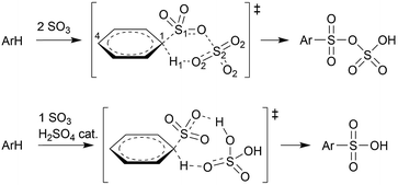 | ||
| Scheme 2 Concerted sulfonation mechanisms in gas phase or apolar solvent with 2 SO3 molecules according to Schleyer and coworkers,12 and with 1 SO3 + H2SO4 catalyst according to Morkovnik and Akopova.23 | ||
The absence of an intramolecular primary hydrogen kinetic isotope effect (KIE)17 led Cerfontain and coworkers to conclude that the reaction step involving proton transfer (step 3 in Scheme 1) is not rate-limiting. However, the KIE may also be small if the C–H bond is only partially broken at the TS.22 In the cyclic transition state structures involving two SO3 molecules, as calculated by Schleyer and coworkers,12 the C–H bond is only slightly elongated at the TS in both CCl3F (0.08 Å) and CH3NO2 (0.10 Å at the second TS). The small bond elongations are consistent with ratios kH/kD = 1.2–1.3, suggesting that step 3 may indeed be rate-limiting.
Importantly however, it is not clear how the participation of two SO3 molecules, as suggested previously,12,21 fits in with the first order rate dependence on the SO3 concentration in apolar solvent. Morkovnik and Akopova23 have proposed an alternative low-barrier mechanism with one SO3 in apolar solvent. In their proposal, a sulfuric acid molecule acts as a catalyst by transferring the proton from benzene to SO3via a relay-race mechanism (Scheme 2).
In this study, we aim to further elucidate the reaction mechanism and explain the experimental data. To fully account for solvation and dynamic effects, ab initio molecular dynamics (AIMD) is the preferred method of choice. The article is organized as follows. We start with the proposal of a new kinetic model, which is validated by a variety of AIMD simulations in gas phase as well as fully solvated in CCl3F and CH3NO2 solvent. Metadynamics (MTD) simulations are performed to study the stability and reactivity of benzene–SO3 and benzene–S2O6 σ-complexes, and to estimate the free energy surface (FES) of the sulfonation reaction. From unbiased MD simulations, we analyze intermolecular interactions between benzene, SO3, and solvent, and we investigate the stability of benzene⋯SO3 and benzene⋯SO3⋯SO3 π-complexes in each environment. Finally, restrained MD (rMD) simulations are performed to evaluate the reactivity of the benzene–S2O6 σ-complex, and of benzene–SO3 + 1 catalytic H2SO4.
Results and discussion
Mechanism and kinetic model
To enhance readability of the study, we start with the proposal of a new sequence of reaction steps given in Scheme 3 based on our calculation results, which are presented in the following sections, and in agreement with experimental data.Here, step 1 represents formation of ArH⋯SO3, a π-complex between the arene and a first SO3 molecule (hereafter named the primary SO3), step 2 is the formation of the ArH⋯SO3⋯SO3 π-complex between ArH⋯SO3 and a second SO3 (the assisting SO3), and step 3 is the actual sulfonation reaction with formation of arenepyrosulfonic acid ArS2O6H, the main reaction product. Step 3 requires a significant reorientation of the two SO3 molecules toward the plane of the benzene ring to make a cyclic proton rearrangement possible. This mechanism differs from the proposed mechanism of Cerfontain and coworkers13–16 in that it does not account for an intermediate σ-complex state. Although its presence is not ruled out, our simulations confirm previous experimental and theoretical data12,24 that the stability of σ-complexes is generally low and may be discarded from the kinetic model. Using steady-state conditions, the reaction rate is given by the rate equation (see Appendix):
 | (1) |
Depending on the solvent, the reaction may be first order or second order in SO3,13,14 which dictates limiting condition 1 (Table 1). In apolar CCl3F solvent, the reaction is first order in SO3, and thus k−1 ≪ k2[SO3], which implies that the ArH⋯SO3 complex must remain stable long enough that it can associate with an assisting SO3 before the primary SO3 dissociates from the arene. In polar CH3NO2, the reaction is second order in SO3 and k−1 ≫ k2[SO3], thus the arene exists as mostly uncomplexed with SO3. Whereas the rate-limiting step could in principle be step 1 or 3 in CCl3F, and step 2 or 3 in CH3NO2 (Table 1, condition 2), our results suggest that (i) the calculated free energy barriers of sulfonation are relatively high, and (ii) the assisting SO3 detaches rapidly from ArH⋯SO3⋯SO3, which strongly suggests that k−2 ≫ k3, thus step 3 is rate-limiting in both solvents.
| Solvent | [SO3]x | Condition 1 | Condition 2 | RLS |
|---|---|---|---|---|
| CCl3F | 1 | k −1 ≪ k2[SO3] | k −2 ≪ k3 | 1 |
| k −2 ≫ k3 | 3 | |||
| CH3NO2 | 2 | k −1 ≫ k2[SO3] | k −2 ≪ k3 | 2 |
| k −2 ≫ k3 | 3 |
In the following sections we validate the proposed mechanism and kinetic model by analyzing a carefully chosen set of advanced AIMD simulations in gas phase and fully solvated in CCl3F and CH3NO2.
Reaction of benzene + 1 SO3
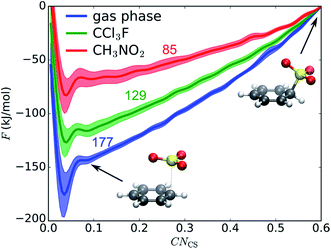
We first examine if a stable σ-complex can be formed between benzene and a single SO3 molecule, as proposed by Cerfontain and coworkers,13–16 and if aromatic sulfonation is possible with only 1 SO3. MTD simulations are performed with one collective variable (CV), the coordination number CNCS that measures bond formation between a benzene carbon and the SO3 sulfur. The resulting potential of mean force (PMF) in gas phase, in CCl3F, and in CH3NO2 is shown in Fig. 1. The benzene⋯SO3 π-complex is located at CNCS ≅ 0.085 (rCS = 2.9 Å). Large free energy differences are observed between the three environments, the σ-complex (CNCS ≅ 0.5–0.6) being most stabilized in the polar CH3NO2. However, no intermediate σ-complex between benzene and SO3 can be discerned from the PMF, in agreement with previous static calculations.12The MTD simulations are continued by further adding Gaussian hills to the reactant state until reaction. No reaction is observed until a barrier height ΔF‡ ≅ 244 kJ mol−1 is reached, which is incompatible with the fast experimental reaction kinetics.15 In conclusion, the MTD simulations suggest that sulfonation of benzene with a single SO3 is not a viable pathway, and can be discarded in the kinetic analysis.
Stability of benzene⋯SO3⋯SO3 and benzene⋯SO3 π-complexes
To assess the validity of steps 1 and 2 of our kinetic model (Scheme 3), the stability of the π-complexes is studied with a series of independent (different starting structures and velocities) and unbiased AIMD simulations starting from the benzene⋯SO3⋯SO3 complex. The results are listed in Table 2 and summarized in Fig. 2.| Initial conditions | Environment | t (ps) | Reactionb |
|---|---|---|---|
| a Total simulation time. b Time at which the event takes place is given between parentheses. | |||
| Unbiased MD | |||
| Benzene⋯SO3⋯SO3 | Gas phase | 120 | Remains stable |
| CCl3F | 200 | →Benzene⋯SO3 + SO3 (30 ps) | |
| 200 | →Benzene⋯SO3 + SO3 (140 ps) | ||
| CH3NO2 | 70 | →Benzene⋯SO3 + SO3 (30 ps) →Benzene + 2 SO3 (70 ps) | |
| 180 | →Benzene⋯SO3 + SO3 (60 ps) →Benzene + 2 SO3 (180 ps) | ||
![[thin space (1/6-em)]](https://www.rsc.org/images/entities/char_2009.gif) |
|||
| Restrained MD | |||
| Benzene–S2O6 | Gas phase | 40 | →Benzene–S2O6H |
| 60 | →Benzene–S2O6H | ||
| CCl3F | 5 | →Benzene–S2O6H | |
| 10 | →Benzene–S2O6H | ||
| CH3NO2 | 200 | Remains stable | |
| Benzene–SO3⋯H2SO4 | Gas phase | 6 | →Benzene–SO3H⋯H2SO4 |
| CCl3F | 170 | →Benzene–SO3H⋯H2SO4 | |
| CH3NO2 | 90 | →Benzene–SO3H⋯H2SO4 | |
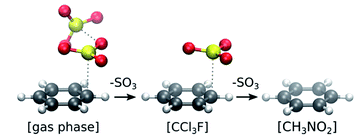 | ||
| Fig. 2 Stability of π-complexes in different solvation models, showing the decrease in number of SO3 molecules complexed with benzene. | ||
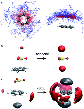
In gas phase, the benzene⋯SO3⋯SO3 complex remains stable throughout the simulation. A clear distinction can be made between the two interacting SO3 molecules (Fig. 3a). The first (primary) SO3 is tightly bound to benzene by strong π interaction between its S atom and the π-conjugated ring system located above the benzene C atoms. The second (assisting) SO3 is loosely bound to the primary SO3 and occasionally strays away from the complex, while remaining at the same side of the ring plane most of the time. In both CCl3F and CH3NO2 solvents, however, one SO3 dissociates from the complex and drifts into the bulk solvent. The resulting benzene⋯SO3 complex remains stable in CCl3F, whereas in CH3NO2 this complex dissociates into solvated benzene and SO3.
Overall, the unbiased MD simulations described here show that the benzene⋯SO3⋯SO3 π-complex is stable in gas phase but unstable in both solvents. The benzene⋯SO3 complex appears relatively stable in CCl3F, consistent with the limiting condition k−1 ≪ k2[SO3] (Table 1), and in agreement with the experimental first order rate in SO3. In contrast, strong interactions with CH3NO2 solvent shift the equilibrium toward separate benzene and SO3 reactants, in accord with k−1 ≫ k2[SO3] (Table 1), in correspondence with the second order rate in SO3. In summary, our simulation results suggest that the reactant species is benzene⋯SO3 in CCl3F and benzene CH3NO2, in agreement with steps 1 and 2 of our kinetic model (Scheme 3).
Specific solvation of reactants
The low stability of the benzene⋯SO3 π-complex in CH3NO2 is attributed to specific solvent interactions. Electrostatic interaction between the positively charged S atom of SO3 and the negatively charged O atoms of CH3NO2 strongly increases upon dissociation of the complex. This solvent interaction is demonstrated in Fig. 3b by the red probability isosurface of CH3NO2 O atoms around SO3, where larger volumes indicate a higher probability of finding an O atom inside the isosurface. Likewise, electrostatic interactions between the benzene π electron cloud and the positively charged methyl group of CH3NO2 (grey), and between the positively charged H atoms of benzene and the O atoms of CH3NO2 (red) markedly increase upon dissociation (Fig. 3c).Reaction of benzene + 2 SO3
The sulfonation reaction starting from the benzene⋯SO3⋯SO3 π-complex, corresponding to step 3 in our kinetic model (Scheme 3), is investigated with MTD and two collective variables, CNCS and CNCO; the latter is the coordination between a benzene C and the O atom of the assisting SO3. In Fig. 4a–c, the resulting 2D FES is shown as the average of three MTD simulations. Again, no intermediate σ-complex is observed in the three environments. The surface is very similar in gas phase and CCl3F, whereas in CH3NO2 the reactant valley is much shallower due to stabilization of TS by the electrostatic field. The position of TS, as indicated with white dots, is similar in the three environments: CV1 ≅ CV2 ≅ 0.6, which corresponds to a cyclic transition state with two SO3 molecules at rCS ≅ 1.84 Å and rCO ≅ 2.7–3.2 Å. In all cases benzenepyrosulfonic acid is formed in one step. In contrast to CV1, the free energy change along the CV2 axis is small. After projecting CV2 onto CV1, a 1D PMF is obtained (Fig. 4d). Mean geometric parameters at TS are shown in Table S2 (ESI†).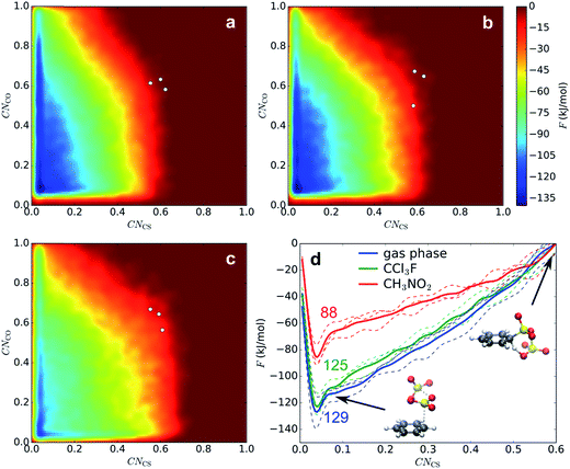 | ||
| Fig. 4 FES of 2D MTD in gas phase (a), CCl3F (b), and CH3NO2 (c), and corresponding projected PMFs along CNCS (d). The given numbers indicate average ΔF‡ values (kJ mol−1). | ||
Low-temperature MD of the σ-complex in CH3NO2 shows that a metastable intermediate state may exist nonetheless (see ESI†). The stability of the σ-complex is however very low, which may in part be due to the BLYP density functional used in this study. Low stabilities of the intermediate state (2–4 kJ mol−1) have also been calculated previously at the M06-2X/6-311+G(2d,2p) level for benzene and 1,4-dichlorobenzene in implicit CH3NO2.12
Reactivity of benzene–S2O6 σ-complex
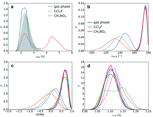
Although we have now established that σ-complexes of benzene and SO3 are fairly unstable, it is insightful to analyze the benzene–SO3 interactions in the σ-complex state and to monitor the influence of the environment on their reactivity toward benzene–S2O6H formation. Additionally, the obtained reactivity information will allow us to decompose the free energy barrier into several discrete contributions.Restrained MD (rMD) simulations are performed of the benzene–SO3 σ-complex + an assisting SO3, which forms a benzene–S2O6 σ-complex. To stabilize the σ-complex, the C1–S1 bond is restrained with a harmonic potential, which keeps CNCS between 0.5 and 0.6 until sulfonation takes place. The results are summarized in Table 2. In gas phase (40–60 ps) and in CCl3F solvent (5–10 ps), a concerted sulfonation reaction takes place by proton transfer to the assisting SO3 with formation of benzenepyrosulfonic acid in one step (Fig. 5). In CH3NO2 solvent, however, no product formation is observed during 200 ps. Two factors contribute to the increased stability of the σ-complex in CH3NO2: (i) stabilization of the zwitterionic TS by the strong solvent electrostatic field, and (ii) competition with the solvent for hydrogen bonding with H1. The latter effect is demonstrated in Fig. 6a, showing a stable intramolecular O2–H1 hydrogen bond in gas phase and CCl3F, whereas in CH3NO2 this hydrogen bond is present only ∼50% of the time.
Solvation effects at the transition state
The segments of rMD trajectories before reaction are analyzed to determine how the transition state geometry is affected by solvation effects. The effects of the solvent on benzene geometry near TS are striking (Fig. 6b–d). The angle α(C4–C1–H1) is calculated as a measure for the degree of sp3 hybridization at C1 and thus the stability of the σ-complex. In the reactant state, the mean angle 〈α〉 = 174° in all three environments, indicating that H1 is located mostly in the plane of the benzene ring and hence C1 is almost purely sp2 hybridized, whereas near TS C1 displays strong sp3 character. The smallest 〈α〉 is measured in CH3NO2 (131°), followed by CCl3F (138°) and gas phase (147°). The strong stabilizing effect of CCl3F is remarkable given its low polarity. The harmonic oscillator model of aromaticity index (HOMA)25 fluctuates around a mean value 〈HOMA〉 = 0.59–0.63 in the reactant state, but degrades near TS, indicating nearly complete loss of aromaticity. This effect is especially strong in CH3NO2 (〈HOMA〉 = −0.19), in comparison with CCl3F (0.02) and gas phase (0.13). The C1–H1 bond is stretched from 〈rCH〉 = 1.102–1.104 Å to 1.124, 1.121, and 1.113 Å in CH3NO2, CCl3F, and gas phase, respectively. In CCl3F, a bimodal distribution is observed due to frequent near-proton transfer events taking place.An alternative pathway in CH3NO2
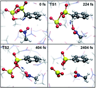
An estimate of the additional free energy barrier required for sulfonation of the benzene-S2O6 σ-complex in CH3NO2 is obtained with restrained MTD (rMTD) (for computational details and PMFs, see ESI†), yielding an average additional ΔF = 12 kJ mol−1. In one of the rMTD runs, an alternative pathway is observed (Fig. 7). First, the C–H bond is weakened by hydrogen bonding interaction with the assisting SO3, which strongly lowers the activation free energy of proton transfer. Next, the proton is transferred to a nitromethane molecule (224 fs, TS1). Shortly thereafter, the proton is transferred from nitromethane to the primary SO3 to form benzenesulfonic acid (404 fs, TS2). Thus, although in this mechanism the assisting SO3 is not the proton acceptor, it still plays an essential role in the reaction by activating the C1–H1 bond. The calculated additional free energy barrier for this pathway ΔF‡ = 14 kJ mol−1, suggesting that this new mechanism is feasible and may compete with the cyclic proton transfer pathway.Free energy decomposition
Combining the results of 1D and 2D MTD and the rMD simulations, the total ΔF‡ can be decomposed into three contributions: (1) benzene⋯SO3 π-complex to benzene–SO3 σ-complex, (2) benzene–SO3 σ-complex to benzene–S2O6 σ-complex, and (3) benzene–S2O6 to TS. In gas phase, the presence of an assisting SO3 strongly reduces the free energy required to form a σ-complex from the π-complex (177 to 129 kJ mol−1). Once the benzene–S2O6 σ-complex is formed, sulfonation proceeds spontaneously. In CCl3F, the assisting SO3 has a slight stabilizing effect on the σ-complex (129 to 125 kJ mol−1). In CH3NO2, the solvent already has a strong stabilizing effect, which causes the additional stabilizing effect of the assisting SO3 to be rather small (85 to 76 kJ mol−1). The combined stabilizing effects lead to an additional free energy barrier required for sulfonation (76 + 12 = 88 kJ mol−1).H2SO4 as a catalyst
As an alternative explanation for the first-order reaction in SO3 in noncomplexing media, Morkovnik and Akopova suggested a relay-race mechanism involving a brønsted acid as a catalyst (Scheme 2).23 The plausibility of this mechanism is verified with rMD simulations of the benzene–SO3 σ-complex, restrained at the C1–S1 bond, in the presence of a H2SO4 molecule. Spontaneous sulfonation takes place in all three environments within 170 ps (Table 2), although the mechanism differs from the mechanism proposed previously23 and depends on the polarity of the environment (Fig. 8). In gas phase and CCl3F, H1 is first transferred from benzene to H2SO4 at TS1, stabilized by one (gas phase) or two (CCl3F) H2SO4–SO3 hydrogen bonds. Proton transfer from H2SO4 to SO3 follows quickly thereafter (TS2, 16 fs). In CH3NO2, first proton transfer occurs from H2SO4 to SO3 (TS1), followed by benzene-to-H2SO4 proton transfer 106 fs later (TS2). We conclude that catalytic amounts of H2SO4 in CCl3F may provide an alternative pathway consistent with first-order kinetics in SO3, however the participation of H2SO4 is not required in our kinetic model. In CH3NO2, the stability of the benzene⋯SO3⋯H2SO4 π-complex is probably too low to meaningfully contribute to the overall reaction.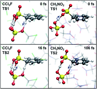 | ||
| Fig. 8 TS1 (top) and TS2 (bottom) in the presence of catalytic H2SO4, corresponding to the first and second proton transfer in CCl3F (left) and CH3NO2 (right). | ||
Conclusions
The mechanism and kinetics of electrophilic aromatic sulfonation have been investigated in great detail with various DFT-based first-principles MD and MTD simulations. Three different environments were compared: gas phase, and fully solvated in explicit apolar (CCl3F) and polar (CH3NO2) solvents. Several alternative reaction mechanisms were evaluated, including with 1 or 2 SO3 molecules, with a catalytic H2SO4 molecule, and with a participating solvent molecule. The kinetic model proposed by Cerfontain and coworkers, involving stable ArH–SO3 and ArH–S2O6 σ-complexes in step 1 and 2, was examined. Our results suggest that both benzene–SO3 and benzene–S2O6 σ-complexes are unstable at room temperature, thus ruling out the Cerfontain model. Our simulation data confirm the static gas phase and implicit solvent calculations performed by Schleyer and coworkers, which suggest that the free energy barrier for sulfonation with a single SO3 is too high to be feasible. In all three environments, a low-energy concerted pathway starting from the benzene⋯SO3⋯SO3 π-complex was found, involving a cyclic transition state with proton transfer from benzene to the assisting SO3, and with formation of benzenepyrosulfonic acid. This mechanism is in agreement with the calculations of Schleyer and coworkers, although in CH3NO2 an intermediate cyclic σ-complex state with low stability was found by them.In order to bring the concerted mechanism into agreement with experimental kinetic data, a new kinetic model was proposed. Steps 1 and 2 represent the formation of ArH⋯SO3 and ArH⋯SO3⋯SO3 π-complexes, respectively, followed by cyclic proton transfer with formation of benzenepyrosulfonic acid in step 3. A rate equation was calculated using the steady-state approximation, and the limiting conditions were determined on the basis of the experimental rate order in SO3. In CCl3F we found that k−1 ≪ k2[SO3], whereas in CH3NO2 the opposite condition k−1 ≪ k2[SO3] applies. The validity of steps 1 and 2 was confirmed with long timescale MD simulations, suggesting that the benzene⋯SO3 π-complex is relatively stable in CCl3F but quickly dissociates in CH3NO2. The mechanism suggested by Morkovnik and Akopova involving one SO3 and a catalytic H2SO4 molecule was shown to provide a viable alternative route to sulfonation in CCl3F. Furthermore, a new and unanticipated mechanism was discovered in CH3NO2, in which two SO3 and one CH3NO2 cooperate in a stepwise proton transfer from benzene to CH3NO2, followed by proton transfer to the primary SO3, leading directly to benzenesulfonic acid. Future research will focus on sulfonation of substituted benzenes and benzene derivatives with SO3 to investigate whether our kinetic model is applicable to a wide range of arenes.
Computational methods
Molecular dynamics
Born–Oppenheimer molecular dynamics simulations are performed at the DFT level with the gradient-corrected BLYP functional,26,27 the DZVP-GTH basis set,28 and Grimme D3 dispersion corrections.29 The BLYP functional has been shown to produce barriers for SN2 and E2 reactions in good agreement with high-level (MP2) calculations.30 The integration time step is set at 1 fs, with snapshots taken every 2 fs. Simulations in solvent are performed in the NVT ensemble, using the canonical sampling through velocity rescaling thermostat31 with a time constant of 50 fs. The reactants are placed inside a periodic cubic box filled with 25 CCl3F or 40 CH3NO2 molecules. The densities are set to the experimental densities of CCl3F (1.48 g ml−1) and CH3NO2 (1.13 g ml−1) at 298 K, with corresponding box lengths 15.847/15.911 Å (CCl3F) and 15.482/15.549 Å (CH3NO2), depending on the number of SO3 molecules present. All AIMD simulations are performed with the CP2K simulation package (version 2.6).32Metadynamics
Most chemical reactions are not accessible in the timescale (typically < 1 ns) that can be reached with AIMD. In order to sample the relevant TS regions, enhanced sampling techniques need to be used. Metadynamics is a nonequilibrium MD method introduced by Laio and Parrinello.33,34 In recent studies, we have successfully used the MTD technique to estimate free energy surfaces in a variety of systems, including heterogeneous catalysis and reactions in solution.35–37 Sampling is advanced by adding Gaussian potential hills along a limited number of carefully chosen collected variables during the simulation, effectively flattening the FES by filling low-energy regions. The FES is then calculated as the opposite of the summation of the Gaussian hills.The hills are added every 25 steps along one or two collective variables (CVs), defined by coordination numbers CN:
 | (2) |
In the 2D MTD, Gaussian hills are placed along two CVs simultaneously: CNCS and CNCO, which allows for a sulfonation with either one or two SO3 molecules. Due to the involvement of proton transfer, however, it is impossible to simulate the reaction in the conventional way, i.e. sampling many forward and reverse reactions by filling both the reactant and product wells with Gaussian hills. Instead, three independent MTD simulations are initiated from different starting geometries and terminated as soon as the proton transfer has taken place. The TS is then taken as the last stationary point along the rCH trajectory before proton transfer takes place.
Analysis
Probability isosurfaces are calculated with the volmap tool of VMD.38 The probability isosurface of CH3NO2 O atoms within 4 Å of the SO3 S atom is calculated with isovalue = 65%. Probability isosurfaces of CH3NO2 O and C atoms within 4 Å of any of the six benzene C atoms are calculated with isovalue = 30%. Conversion of the 2D FES into a 1D PMF is achieved by projecting CV2 onto CV1, and free energy barriers are calculated as the free energy difference between the TS and the reactant state.36Appendix
Here we derive the rate equation (eqn (1)). Let A = ArH, B = SO3, C = ArH⋯SO3, D = ArH⋯SO3⋯SO3, E = ArS2O6H. Using the steady-state approximation, we have | (3) |
 | (4) |
From eqn (3)–(4):
 | (5) |
 | (6) |
The form of this equation differs from the rate equation presented by Lammertsma and Cerfontain,17 who in the denominator neglect k−2 in comparison to k3 in the term (k−2 + k3)k2[B], but not in (k−2 + k3)k−1. No rationale was given for the partial neglect of k−2, and it does not seem to simplify the kinetic analysis.
Acknowledgements
The computational resources and services used in this work were provided by the VSC (Flemish Supercomputer Center), funded by the Hercules Foundation and the Flemish Government – department EWI. P. G. and F. D. P. wish to thank the Fund for Scientific Research – Flanders (FWO) and the Vrije Universiteit Brussel (VUB) for their continuous support. They also specifically want to mention the Strategic Research Program awarded to the ALGC group by the VUB which started on January 1, 2013.References
- E. A. Knaggs and M. J. Nepras, in Kirk-Othmer Encyclopedia of Chemical Technology, John Wiley & Sons, Inc., 2000, DOI:10.1002/0471238961.1921120611140107.a01.
- M. B. Smith and J. March, in March's Advanced Organic Chemistry, John Wiley & Sons, Inc., 2006, DOI:10.1002/9780470084960.ch11, pp. 657–751.
- J. S. Carey, D. Laffan, C. Thomson and M. T. Williams, Org. Biomol. Chem., 2006, 4, 2337–2347 CAS.
- G. P. Dado, E. A. Knaggs and M. J. Nepras, in Kirk-Othmer Encyclopedia of Chemical Technology, John Wiley & Sons, Inc., 2000, DOI:10.1002/0471238961.1921120611140107.a01.pub2.
- D. W. Roberts, Org. Process Res. Dev., 2003, 7, 172–184 CrossRef CAS.
- Y. Chen, Y. Su, F. Jiao and G. Chen, RSC Adv., 2012, 2, 5637–5644 RSC.
- C. M. Suter and A. W. Weston, in Organic Reactions, John Wiley & Sons, Inc., 2004, vol. 3, pp. 141–197 Search PubMed.
- B. Galabov, D. Nalbantova, P. v. R. Schleyer and H. F. Schaefer, Acc. Chem. Res., 2016, 49, 1191–1199 CrossRef CAS PubMed.
- J. Kong, B. Galabov, G. Koleva, J.-J. Zou, H. F. Schaefer and P. v. R. Schleyer, Angew. Chem., Int. Ed., 2011, 50, 6809–6813 CrossRef CAS PubMed.
- B. Galabov, G. Koleva, S. Simova, B. Hadjieva, H. F. Schaefer and P. v. R. Schleyer, Proc. Natl. Acad. Sci. U. S. A., 2014, 111, 10067–10072 CrossRef CAS PubMed.
- G. Koleva, B. Galabov, B. Hadjieva, H. F. Schaefer and P. v. R. Schleyer, Angew. Chem., Int. Ed., 2015, 54, 14123–14127 CrossRef CAS PubMed.
- G. Koleva, B. Galabov, J. Kong, H. F. Schaefer and P. v. R. Schleyer, J. Am. Chem. Soc., 2011, 133, 19094–19101 CrossRef CAS PubMed.
- J. K. Bosscher and H. Cerfontain, Recl. Trav. Chim. Pays-Bas, 2010, 87, 873–887 CrossRef.
- J. K. Bosscher and H. Cerfontain, Tetrahedron, 1968, 24, 6543–6555 CrossRef CAS.
- J. K. Bosscher and H. Cerfontain, J. Chem. Soc. B, 1968, 1524–1526, 10.1039/j29680001524.
- H. Cerfontain, Recl. Trav. Chim. Pays-Bas, 2010, 104, 153–165 CrossRef.
- K. Lammertsma and H. Cerfontain, J. Chem. Soc., Perkin Trans. 2, 1980, 28–32, 10.1039/p29800000028.
- H. Cerfontain and A. Koeberg-Telder, Recl. Trav. Chim. Pays-Bas, 2010, 89, 569–574 CrossRef.
- A. Koeberg-Telder and H. Cerfontain, Recl. Trav. Chim. Pays-Bas, 2010, 90, 193–206 CrossRef.
- J. O. Morley and D. W. Roberts, J. Org. Chem., 1997, 62, 7358–7363 CrossRef CAS PubMed.
- J. O. Morley, D. W. Roberts and S. P. Watson, J. Chem. Soc., Perkin Trans. 2, 2002, 538–544, 10.1039/b109338j.
- F. H. Westheimer, Chem. Rev., 1961, 61, 265–273 CrossRef CAS.
- A. S. Morkovnik and A. R. Akopova, Dokl. Chem., 2013, 450, 122–126 CrossRef CAS.
- F. Kučera and J. Jančář, Polym. Eng. Sci., 1998, 38, 783–792 Search PubMed.
- T. M. Krygowski and M. K. Cyranski, Phys. Chem. Chem. Phys., 2004, 6, 249–255 RSC.
- A. D. Becke, Phys. Rev. A: At., Mol., Opt. Phys., 1988, 38, 3098–3100 CrossRef CAS.
- C. Lee, W. Yang and R. G. Parr, Phys. Rev. B, 1988, 37, 785–789 CrossRef CAS.
- S. Goedecker, M. Teter and J. Hutter, Phys. Rev. B: Condens. Matter, 1996, 54, 1703–1710 CrossRef CAS.
- S. Grimme, J. Antony, S. Ehrlich and H. Krieg, J. Chem. Phys., 2010, 132, 154104 CrossRef PubMed.
- B. Ensing and M. L. Klein, Proc. Natl. Acad. Sci. U. S. A., 2005, 102, 6755–6759 CrossRef CAS PubMed.
- G. Bussi, D. Donadio and M. Parrinello, J. Chem. Phys., 2007, 126, 014101 CrossRef PubMed.
- J. Hutter, M. Iannuzzi, F. Schiffmann and J. VandeVondele, Wiley Interdiscip. Rev.: Comput. Mol. Sci., 2014, 4, 15–25 CrossRef CAS.
- A. Laio and F. L. Gervasio, Rep. Prog. Phys., 2008, 71, 126601 CrossRef.
- A. Laio and M. Parrinello, Proc. Natl. Acad. Sci. U. S. A., 2002, 99, 12562–12566 CrossRef CAS PubMed.
- S. L. C. Moors, B. Brigou, D. Hertsen, B. Pinter, P. Geerlings, V. Van Speybroeck, S. Catak and F. De Proft, J. Org. Chem., 2016, 81, 1635–1644 CrossRef CAS PubMed.
- S. L. C. Moors, K. De Wispelaere, J. Van der Mynsbrugge, M. Waroquier and V. Van Speybroeck, ACS Catal., 2013, 3, 2556–2567 CrossRef CAS.
- J. Van der Mynsbrugge, S. L. C. Moors, K. De Wispelaere and V. Van Speybroeck, ChemCatChem, 2014, 6, 1906–1918 CrossRef CAS.
- W. Humphrey, A. Dalke and K. Schulten, J. Mol. Graphics, 1996, 14, 33–38 CrossRef CAS PubMed , 27-38.
Footnote |
| † Electronic supplementary information (ESI) available. See DOI: 10.1039/c6sc03500k |
| This journal is © The Royal Society of Chemistry 2017 |

