DOI:
10.1039/C4RA06977C
(Paper)
RSC Adv., 2014,
4, 44457-44461
Plasmonic cavities derived from silver nanoparticles atop a massed silver surface for surface enhancement Raman scattering†
Received
11th July 2014
, Accepted 4th September 2014
First published on 4th September 2014
Abstract
Various plasmonic cavities (PC) are formed by positioning silver nanocubes or nanospheres on a massed silver surface, being magnificently useful for surface enhancement Raman scattering (SERS) application. In this case, a red-shift in the wavelength of surface plasmon resonance (SPR) increases with the decrease in gap width according to the simulation results of absorption spectra by finite-difference time-domain method. Nanocube-insulator-metal geometry with a 2 nm gap width (2-NcIM) possesses strong electromagnetic (EM) field distribution and its PC forms near 633 nm radiation. In order to validate the simulation results, two geometries were selected for SERS experiments by using rhodamine 6G (R6G) as a model compound with 633 nm laser irradiation. To our surprise, 2-NcIM possesses respectively 2.06 × 10⁴ and 2.41 × 10⁴ times experimental and simulated enhancement factors (EFs) of nanosphere-insulator-metal geometry with a 2 nm gap width (1.5 ± 0.25 × 10⁴ and 4.82 × 10⁴), confirming the validity of the simulation results. It also prompts us to not only clarify the role of our special substrates in extra high EF for SERS application but also to design innovative, highly sensitive, and low cost substrates via the simulation results.
Introduction
Surface plasmon resonance (SPR) is triggered by the coherent oscillations of free electrons at metal–dielectric interfaces with excitation by electromagnetic (EM) wave irradiation.1,2 This unique property had been extensively studied for signal amplification applications, such as waveguides,3 reflectors,4 and splitters,5 and shows high potential for application in Surface Enhanced Raman Scattering (SERS).6–8 The SPR wavelengths of noble metals (Al, Ag, and Au) nanoparticles are in the region of visible light, which is suitable to enhance Raman signals due to the match with the commonly used 532, 633, and 780 nm lasers.9–11 The coupling between two metal nanoparticles at the nanogaps to resonate the plasmons at the interfaces of metals, which is called the plasmonic cavity (PC), leading to strong SPR had been investigated and widely applied to SERS.12–15 However, it is hard to create a high density of SPR via this method due to the difficulty in decreasing the gap width with the extremely low value. Recently, various geometries of metal nanoparticles atop massed metal surfaces with ultrathin insulators as the gaps (NpIM) have been extensively studied both theoretically16,17 and experimentally12–15 due to the ease of creating large areas and high density of SPR. NpIM with the geometry of gold nanospheres atop a massed gold surface had been used as a convenient and highly sensitive SERS sensor for detection of biomolecules by Mahajan et al.18 Xia et al. also demonstrated that a high enhancement factor (EF) can be achieved with silver nanocubes atop a silver film geometry using chemically synthesized SiO2 around the silver nanocubes as the insulator.19 Catherine et al. used self-assembled analyte around gold nanocubes atop a gold surface as the substrates to obtain an extremely high EF for detecting 4-mercaptobenzoic acid.20 Silver nanocubes atop a silver surface functionalized by 1,2-ethanedithiol monolayer as an insulator have been found to effectively enhance rhodamine 6G (R6G) signals.21
In addition to the strong SPR created by the PC, the gap width and shape of metal nanoparticles are also important for varying the intensity and resonance wavelength of SPR. Alexander et al. found that high SERS signals can be achieved by adjusting the interdistance between gold nanorods.22 The effect of various gap widths between the silver nanocubes on the shift of SPR wavelength and the calculated SERS EFs has been studied by Rabin et al.23 The dependence of SERS detection on the shape of gold nanoparticles has been investigated by Catherine et al.24 However, a systematic investigation of the effects of gap width and shape of nanoparticles on PC in the NpIM geometry has not been carried out. In this study, the simulated absorption spectra and the EM field density diagrams of silver nanocubes atop a massed silver surface with air as the insulator (NcIM) with 2, 3, 4, 5, and 10 nm gap widths under the wavelength of maximum absorbance (λmax) and 633 nm laser irradiation were simulated via finite difference time domain (FDTD) method to investigate the role of gap width in the PC of the NcIM. Comparisons between the simulated and experimental results of NcIM and the silver nanosphere atop a massed silver surface with air as the insulator (NsIM) were also conducted to understand the shape effect on PC and the SERS performance.
Results and discussion
The simulated absorption spectra of the NcIM with 2, 3, 4, 5, and 10 nm gap widths (denoted as 2-NcIM, 3-NcIM, 4-NcIM, 5-NcIM, and 10-NcIM) are shown in Fig. 1. The inset shows the scheme of NcIM geometry with 50 nm silver nanocubes under polarized laser irradiation pointing vertically downwards. NcIM with 1 nm gap width is beyond the discussion due to the high technical difficulty in fabricating such a substrate. The absorption peaks below 450 nm are denoted as high order mode except for the second peak of 10-NcIM. The simulated adsorption peaks at 670, 577, 526, 493, and 420 nm for 2-NcIM, 3-NcIM, 4-NcIM, 5-NcIM, and 10-NcIM, respectively, are the PC mode, resulting from the coupling of surface plasmons at the nanoparticles and propagating surface plasmons on the massed silver surface. The absorbance intensity increases with the decrease in gap width of NcIM, showing stronger plasmon coupling between silver nanocubes and the surface with smaller gap width. The redshift of the PC mode increases with the decrease in the gap width of NcIM, which is consistent with the results of the dispersion relation of metal–insulator–metal (MIM) geometry which show that the resonance frequency at the same wave vector decreases with the decrease in the gap width of MIM. The redshift of the PC mode means that the PC of NcIM with smaller gap width should be excited under the longer wavelength laser irradiation to obtain the maximum resonance.
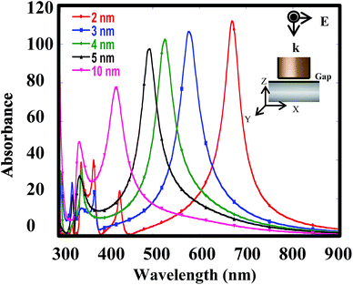 |
| | Fig. 1 Simulated absorption spectra for the NcIM with 2, 3, 4, 5, and 10 nm gaps. Note: the absorbance is calculated from the ratio of the EM field amplitude with substrate to that of the background (without substrate). | |
The EM field densities in the X–Z plane of 2-NcIM, 3-NcIM, 4-NcIM, 5-NcIM, and 10-NcIM under λmax laser irradiation are shown in Fig. 2a. The area of the strong EM density decreases with the increase of the gap width in the NcIM geometry, which is consistent with the intensity in the simulated absorption spectra. The smaller intensity of the PC results from weaker coupling of surface plasmons at the nanoparticles with propagating surface plasmons on the massed silver surface with the larger gap width. Especially, the EM field density in 10-NcIM is concentrated at the corners of the cube, showing that the resonance is weaker for the coupling between silver surfaces than the sharp corner effect of silver nanocubes. In spite of the strong EM density enhancement from PC under λmax laser irradiation, these wavelengths mismatch the laser wavelength (633 nm) commonly used to induce such strong resonance. The EM field densities of NcIMs under the 633 nm laser irradiation were simulated as shown in Fig. 2b. The EM field intensity of the PC in 2-NcIM is stronger than 3-NcIM owing to the smaller deviation between λmax and 633 nm for 2-NcIM (37 = 670 (λmax) − 633 nm) than 3-NcIM (56 = 633 − 577(λmax) nm). The intensity of the PC for 4-NcIM, 5-NcIM, and 10-NcIM is almost zero due to the large deviation between λmax and 633 nm. According to the above results, the wavelength of the PC should match the incident laser to induce strong resonance for SERS application. The 2 nm gap width was chosen for the investigation of the shape effect of silver nanoparticles on SERS via simulation and experiments due to the close match between its λmax and 633 nm laser.
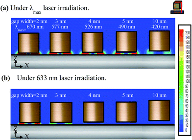 |
| | Fig. 2 The EM field densities of 2-NcIM, 3-NcIM, 4-NcIM, 5-NcIM, and 10-NcIM in the X–Z plane under (a) λmax laser irradiation and (b) 633 nm laser irradiation. | |
In order to investigate the shape effect of silver nanoparticles on the PC, the simulated absorption spectra of silver nanocubes atop the massed silver surface without the insulator (denoted as NcM), 2-NcIM, and silver nanosphere with diameter of 50 nm atop the massed silver surfaces without and with a 2 nm gap width (denoted as NsM and 2-NsIM) are shown in Fig. 3. Except for 2-NcIM, all curves were multiplied several times for significant contrast. 2-NcIM possesses stronger intensity of the PC mode than NcM, NsM, and 2-NsIM, depicting that the stronger PC is derived from the parallel silver surface than the curve silver surface. However, the intensity of the PC mode at the 530 nm can be shown in NsM rather than 2-NsIM. This special behavior can be illustrated via the simulation of the EM field density of these four substrates. In the case of NcM, 2-NcIM, NsM, and 2-NsIM under λmax laser irradiation, the EM field densities in the X–Z and X–Y planes are shown in Fig. 4a and b, respectively. Larger areas of EM density and higher intensity of PC are present in 2-NcIM than NcM, NsM, and 2-NsIM, which is consistent with the results of the simulated absorption spectra. Due to the direct contact between the silver nanocubes and the surface, there is no PC observed in NcM. At the center of silver nanosphere in NsM, the EM field density is almost zero due to the direct contact. As the position moves away from the center, the intensity will decrease, resulting from the increase in the gap width lowering the plasmon coupling between the silver nanospheres and the surface. A similar phenomenon in 2-NsIM was also observed with the smaller intensity of EM field density. Accordingly, the intensity of the PC will largely decay when the gap width is larger than 2 nm. The higher EM field density and the larger extended PC area can be obtained due to the larger PC derived from the parallel silver surface than the curved silver surface.
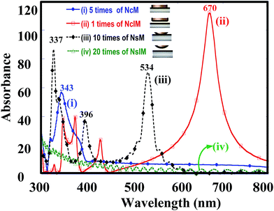 |
| | Fig. 3 The simulated absorption spectra for (i) 5 times the absorbance of NcM, (ii) 1 times the absorbance of NcIM, (iii) 10 times the absorbance of NsM and (iv) 20 times the absorbance of NsIM. Note: the observable waves of NsIM in (iv) are noise from Fourier transform. | |
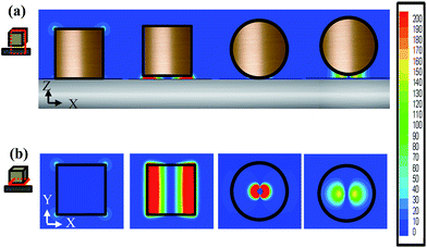 |
| | Fig. 4 The EM field densities of NcM, 2-NcIM, NsM and 2-NsIM at (a) the X–Z plane in the middle of nanoparticle and (b) the X–Y plane in the middle of the nanogap. | |
In order to confirm the validity of the simulation results, we chose 2-NcIM and 2-NsIM for SERS experiments by using R6G as the model compound. From our previous study,21 the gap width was estimated as 2 nm in the case of the 50 nm silver nanocubes self-assembled on the massed silver surface. It provides us with a good chance to make a comparison between simulation results and SERS experiments. The Raman spectra for detecting R6G molecules on a microscopic slide, 2-NsIM, and 2-NcIM under 633 nm laser irradiation are shown in Fig. 5. The characteristic peaks of the standard R6G signals can be observed in the microscopic slide spectrum, which is measured under high R6G concentration (10−1 M) preventing the effect of noise signals. These R6G characteristic peaks with negligible noise signals are also shown in the spectra of 2-NsIM and 2-NcIM, depicting their high SERS sensitivity. The detection limits for the microscopic slide, 2-NsIM, and 2-NcIM are 10−1, 10−6, and 10−9 M R6G solution, respectively. The lower detection limit of 2-NcIM than 2-NsIM represents the more R6G molecules detected due to the larger extended PC area for 2-NcIM than 2-NsIM. The high detection limit of the microscopic slide comes from the lack of nanostructure to create SPR. The Raman intensity is higher for 2-NcIM than 2-NsIM at the lower R6G concentration due to the higher EM field density. In order to compare experimental results with the simulations, the experimental EFs and simulated EFs were calculated according to eqn (S1) and (S2), respectively (ESI†). Table 1 shows that the experimental EFs and simulated EFs are 3.1 × 10⁸ and 1.16 × 10⁹ for 2-NcIM and 1.5 × 10⁴ and 4.82 × 10⁴ for 2-NsIM, respectively. The experimental EFs are statistically calculated from 20 different R6G signals at 1360 cm−1 using a 95% confidence interval with t statistics (ESI†). Excitingly, 2NcIM possesses 2.06 × 10⁴ and 2.41 × 10⁴ times experimental and simulated EFs of 2-NsIM, respectively (1.5 ± 0.25 × 10⁴ and 4.82 × 10⁴), confirming the validity of the simulation results. Combining the experimental and the simulation results, the PC derived from the parallel silver surface possess higher EFs and lower detection limits than the curved silver surface due to the higher EM field density and the larger extended PC area. The high consistence between the experimental and simulation results provides us a new path to investigate the various PC for SERS application via the simulation results.
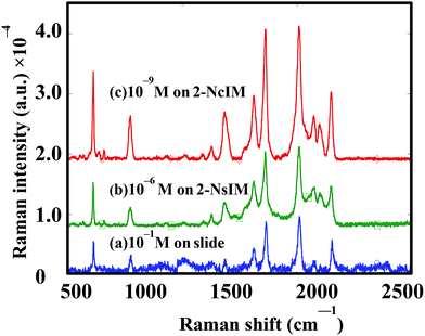 |
| | Fig. 5 SERS spectra under the 633 nm laser irradiation for (a) 10−1 M R6G solution on microscope slide, (b) 10−6 M R6G solution on 2-NsIM, and (c) 10−9 M R6G solution on 2-NcIM. | |
Table 1 The comparison of EFs between 2-NcIM and 2-NsIM
| EFs |
Substrates |
| 2-NcIM |
2-NsIM |
| Simulated |
1.16 × 10⁹ |
4.82 × 10⁴ |
| Experimental |
(3.08 ± 0.07) × 108 |
(1.52 ± 0.05) × 103 |
Conclusions
This study investigates the effects of gap width and shape of silver nanoparticles positioned on a massed silver surface on PC formation and the corresponding SERS responses. The redshift and intensity of the PC increase with the decreasing gap width of the NcIM geometry. As for the shape effect of nanoparticles positioned on a massed silver surface, the stronger PC is induced under the λmax laser irradiation for the parallel silver surface than the curved silver surface. In this case, 2-NcIM demonstrates the R6G characteristic peaks without noise signals in 10−9 M R6G solution. Meanwhile, 2-NcIM possesses 2.06 × 10⁴ and 2.41 × 10⁴ times experimental and simulated EFs of 2-NsIM, respectively (1.5 ± 0.25 × 10⁴ and 4.82 × 10⁴), confirming the validity of the simulation results. In the future, novel SERS substrates with various PCs can be designed for SERS application under different wavelength laser irradiation.
Experimental
Electromagnetic simulations by FDTD method
The FDTD program MEEP was used to perform the simulation.25 The substrates assumed in the simulations are 50 nm Ag nanosphere/Ag nanocube atop the massed 80 nm thickness Ag surface with/without a 2 nm dielectric spacer, which closely matched the SERS samples (in reality, 49.6 nm Ag nanosphere and 54.3 nm Ag nanocube). The excitation source was a linearly polarized radiation wave (polarized in the X–Y plane). The grid size used for the nanocube is 0.5 nm and that for the nanosphere is 0.2 nm. The surrounding boundaries were the perfectly matched layers. The dielectric constant of silver used here was from the review.26 In absorption spectra, the EM field amplitude with/without substrate is collected after a state function (30–300![[thin space (1/6-em)]](https://www.rsc.org/images/entities/char_2009.gif) 000 nm) EM wave excitation. Fourier transform is used to distinguish varying wavelength and the absorbance is calculated by the ratio of the EM field amplitude with substrate to that of background (without substrate). The maximum absorbance in the absorption spectra is defined as λmax. The EM field densities diagrams are calculated from the ratio of the EM field amplitude with substrate to that of background under λmax (or 633 nm) EM wave excitation.
000 nm) EM wave excitation. Fourier transform is used to distinguish varying wavelength and the absorbance is calculated by the ratio of the EM field amplitude with substrate to that of background (without substrate). The maximum absorbance in the absorption spectra is defined as λmax. The EM field densities diagrams are calculated from the ratio of the EM field amplitude with substrate to that of background under λmax (or 633 nm) EM wave excitation.
The preparation of SERS substrates
The synthesis of the Ag nanocubes and the nanospheres by chemical methods that offers good control over their shape is referenced from Xia.27 The formation of silver nanocubes could be easily confirmed from tunnelling electron microscopy and the average sizes of the silver nanocubes and nanospheres are 54.3 ± 1.45 nm and 49.6 ± 1.01 nm (the details are listed in ESI III†). The Ag surface was prepared by thermal evaporation of Ag (99.99% purity) onto the cleaned indium tin oxide substrates. To prepare a spacer on the substrates, the Ag surface was soaked in a 0.1% 1,2-ethanedithiol solution for 5 minutes with sonication and washed carefully to remove all unbonded 1,2-ethanedithiol. Then, the Ag surface with a 1,2-ethanedithiol monolayer was soaked in the Ag nanocubes/Ag nanospheres solution for 5 minutes with sonication. The substrates were cleaned several times by ethanol and sonicated to remove the unbonded nanoparticles.
Raman spectra
Raman spectra were taken by a confocal microscopic Raman spectrometer (In Via Raman microscope, RENISHAW, United Kingdom) using 633 nm radiation from the excitation of a He–Ne laser. Before each measurement, the Raman shift was calibrated by the signal of 520.7 cm−1 from a standard silicon wafer. The reported spectra were the results of a single 1 s accumulation in a range of 500–2000 cm−1 and the characteristic R6G peak at 1360 cm−1 was selected to calculate the enhancement factor and the standard deviation from the average of 20 spectra in different sites.
Acknowledgements
Financial support from National Science Council, Taiwan (Contract no. NSC 101-2221-E-006-227-MY3) and Headquarters of University Advancement, National Cheng Kung University, Taiwan (Contract no. D100-33B34) is acknowledged. The authors appreciate Prof. T. Y. Chen from National Tsinghua University, Taiwan for their valuable discussions and Mr K. W. Tasi, doctorate student in Wen's group, for his help in preparing the manuscript.
Notes and references
- H. Raether, Surface Plasmons on Smooth and Rough Surfaces and on Gratings, Springer-Verlag, Berlin, Germany, 1988 Search PubMed.
- S. A. Maier, Plasmonics: Fundamentals and Applications, Springer-Verlag, NewYork, 2007 Search PubMed.
- F. B. Arango, A. K. Wadrin and A. F. Koenderink, ACS Nano, 2012, 6, 10156 CrossRef PubMed.
- M. Tian, P. Lu, L. Chen, D. Liu and N. Peyghambarian, Opt. Commun., 2012, 285(24), 5122 CrossRef CAS PubMed.
- B. Huang, F. Yu and R. N. Zare, Anal. Chem., 2007, 79, 2979 CrossRef CAS PubMed.
- J. F. Li, X. D. Tian, S. B. Li, J. R Anema, Z. L. Yang, Y. Ding, Y. F. Wu, Y. M. Zeng, Q. Z. Chen, B. Ren, Z. L. Wang and Z. Q. Tian, Nat. Protoc., 2013, 8(1), 52 CrossRef CAS PubMed.
- H. J. Wu, J. Henzie, W. C. Lin, C. Rhodes, Z. Li, E. Sartorel, J. Thorner and P. Yang, Nat. Methods, 2012, 9(12), 1189 CrossRef CAS PubMed.
- S. Lin, W. Zhu, Y. Jin and K. B. Crozier, Nano Lett., 2013, 13, 559–563 CrossRef CAS PubMed.
- J. B. Lassiter, F. McGuire, J. J. Mock, C. Ciracì, R. T. Hill, B. J. Wiley, A. Chilkoti and D. R. Smith, Nano Lett., 2013, 13, 5866 CrossRef CAS PubMed.
- M. Yi, D. Zhang, P. Wang, X. Jiao, S. Blair, X. Wen, Q. Fu, Y. Lu and H. Ming, Plasmonics, 2011, 6, 515 CrossRef CAS.
- F. J. Beck, A. Polman and K. R. Catchpole, J. Appl. Phys., 2009, 105, 114310 CrossRef PubMed.
- K. L. Wustholz, A. I. Henry, J. M. McMahon, R. G. Freeman, N. Valley, M. E. Piotti, M. J. Natan, G. C. Schatz and R. P. Van Duyne, J. Am. Chem. Soc., 2010, 132(31), 10903 CrossRef CAS PubMed.
- R. W. Taylor, R. J. Coulston, F. Biedermann, S. Mahajan, J. J. Baumberg and O. A. Scherman, Nano Lett., 2013, 13, 5985 CrossRef CAS PubMed.
- Z. B. Wang, B. S. Luk'yanchuk, W. Guo, S. P. Edwardson, D. J. Whitehead, L. Li, Z. Liu and K. G. Watkins, J. Chem. Phys., 2008, 128(9), 094705 CrossRef CAS PubMed.
- M. Futamata, Y. Maruyama and M. Ishikawa, J. Phys. Chem. B, 2003, 117 Search PubMed.
- N. Grillet, D. Manchon, F. Bertorelle, C. Bonnet, M. Broyer, E. Cottancin, J. Lermé, M. Hillenkamp and M. Pellarin, ACS Nano, 2011, 5, 9450 CrossRef CAS PubMed.
- E. Hao and G. C. Schatz, J. Chem. Phys., 2004, 120, 357 CrossRef CAS PubMed.
- L. Li, T. Hutter, U. Steiner and S. Mahajan, Analyst, 2013, 138, 4574–4578 RSC.
- M. Rycenga, X. Xia, C. H. Moran, F. Zhou, D. Qin, Z. Y. Li and Y. Xia, Angew. Chem., Int. Ed., 2011, 50(24), 5473–5477 CrossRef CAS PubMed.
- N. S. Patrick and J. M. Catherine, J. Phys. Chem. A, 2009, 113, 3973 CrossRef PubMed.
- S. C. Cheng and T. C. Wen, Mater. Chem. Phys., 2014, 143, 1331–1337 CrossRef CAS PubMed.
- K. D. Alexander, K. Skinner, S. Zhang, H. Wei and R. Lopez, Nano Lett., 2012, 10, 4488 CrossRef PubMed.
- S. Y. Lee, L. Hung, G. S. Lang, J. E. Cornett, I. D. Mayergoyz and O. Rabin, ACS Nano, 2010, 4(10), 5763 CrossRef CAS PubMed.
- J. O. Christopher, G. Anand, K. S. Tapan and J. M. Catherine, Anal. Chem., 2005, 77, 3261 CrossRef PubMed.
- S. Mubeen, S. Zhang, N. Kim, S. Lee, S. Krämer, H. Xu and M. Moskovits, Nano Lett., 2012, 12, 2088–2094 CrossRef CAS PubMed.
- S. Astilean, Ph. Lalanne and M. Palamaru, Opt. Commun., 2000, 175, 265–273 CrossRef CAS.
- Y. Sun and Y. Xia, Science, 2002, 298, 2176 CrossRef CAS PubMed.
Footnote |
| † Electronic supplementary information (ESI) available. See DOI: 10.1039/c4ra06977c |
|
| This journal is © The Royal Society of Chemistry 2014 |
Click here to see how this site uses Cookies. View our privacy policy here. 


