
 Open Access Article
 This Open Access Article is licensed under a
 Creative Commons Attribution 3.0 Unported Licence
Wetting on silicone surfaces
Lukas
Hauer
 *ab,
Abhinav
Naga
cd,
Rodrique G. M.
Badr
e,
Jonathan T.
Pham
f,
William S. Y.
Wong
g and
Doris
Vollmer
b
*ab,
Abhinav
Naga
cd,
Rodrique G. M.
Badr
e,
Jonathan T.
Pham
f,
William S. Y.
Wong
g and
Doris
Vollmer
b
aInstitute for Biology, Humboldt-Universität zu Berlin, 10115 Berlin, Germany
bPhysics at Interfaces, Max Planck Institute for Polymer Research, Ackermannweg 10, 55128 Mainz, Germany. E-mail: lukas.hauer@hu-berlin.de
cDepartment of Physics, Durham University, DH1 3LE, UK
dInstitute for Multiscale Thermofluids, School of Engineering, The University of Edinburgh, Edinburgh EH9 3FD, UK
eInstitut für Physik, Johannes Gutenberg-Universität Mainz, Staudingerweg 7-9, 55099 Mainz, Germany
fDepartment of Chemical and Environmental Engineering, University of Cincinnati, Cincinnati, 45221 OH, USA
gDepartment of Applied Physics, School of Science, Aalto University, 02150 Espoo, Finland
First published on 2nd July 2024
Abstract
Silicone is frequently used as a model system to investigate and tune wetting on soft materials. Silicone is biocompatible and shows excellent thermal, chemical, and UV stability. Moreover, the mechanical properties of the surface can be easily varied by several orders of magnitude in a controlled manner. Polydimethylsiloxane (PDMS) is a popular choice for coating applications such as lubrication, self-cleaning, and drag reduction, facilitated by low surface energy. Aiming to understand the underlying interactions and forces, motivated numerous and detailed investigations of the static and dynamic wetting behavior of drops on PDMS-based surfaces. Here, we recognize the three most prevalent PDMS surface variants, namely liquid-infused (SLIPS/LIS), elastomeric, and liquid-like (SOCAL) surfaces. To understand, optimize, and tune the wetting properties of these PDMS surfaces, we review and compare their similarities and differences by discussing (i) the chemical and molecular structure, and (ii) the static and dynamic wetting behavior. We also provide (iii) an overview of methods and techniques to characterize PDMS-based surfaces and their wetting behavior. The static and dynamic wetting ridge is given particular attention, as it dominates energy dissipation, adhesion, and friction of sliding drops and influences the durability of the surfaces. We also discuss special features such as cloaking and wetting-induced phase separation. Key challenges and opportunities of these three surface variants are outlined.
 Lukas Hauer | Lukas Hauer studied mechanical engineering at TU Darmstadt (Germany) and Tongji University (China) with a focus on modeling and simulating thermo-fluid transport. He completed a PhD at the MPI for Polymer Research in 2023, where he investigated wetting and phase change on soft materials in experiments and theory. Currently, he is a postdoctoral researcher at the Interfacial Cell Biology lab at Humbodlt-Universität zu Berlin, exploring wetting phenomena of bio-condensates and cellular membranes. When not in the lab, he likes to explore the world through hiking, reading, and traveling. |
 Abhinav Naga | Abhinav Naga received his undergraduate degree in Physics from the University of Oxford (UK) in 2017 before completing a PhD at the Max Planck Institute for Polymer Research (Germany) in 2021. During his PhD, he developed experimental techniques to study interactions between droplets, particles, and surfaces. Following his PhD, he continued researching topics related to droplets and interfacial phenomena using lattice Boltzmann simulations at Durham University (UK). Currently, he is based at the University of Edinburgh (UK) as a National Fellow in Fluid Dynamics. When he is not thinking hard about droplets, he is probably running, cycling, or hiking. |
 Rodrique G. M. Badr | Rodrique Badr received his BS and MS degrees in physics from the American University of Beirut, Lebanon. He is currently a final year PhD candidate at the Institute of Physics at Johannes Gutenberg University, Mainz. There, he pursues computational and theoretical investigations, primarily dealing with droplets on polymer brushes and gels, as well as focusing on other polymeric systems, such as polymers in confinement and biomolecules. When not debugging codes or deriving equations, you can find him trying to make sense of a piece of modern art; then, after failing at it, sitting in a nice café or taking a walk. |
 Jonathan T. Pham | Jonathan Pham is an associate professor at the University of Cincinnati in Chemical Engineering and Materials Science and Engineering. He received a BS from The Ohio State University in Materials Science, a PhD from the University of Massachusetts Amherst in Polymer Science, was a Chateaubriand Fellow at the ESPCI-ParisTech, and a Humboldt Postdoctoral Fellow at the Max Planck Institute for Polymer Research. Prior to Cincinnati, he was an assistant professor at the University of Kentucky. His research group focuses broadly on soft materials and interfaces for a range of applications, from adhesives, coatings, and lubricants to personal care products. |
 William S. Y. Wong | William S. Y. Wong received his BEng in Chemical Engineering from the National University of Singapore in 2013 before completing a PhD at the Australian National University in 2018. During his PhD, he worked on interfacial-engineering of hierarchical textures for liquid manipulation. Following his PhD, he expanded into the study of interfacial phenomena, including frosting, foaming, and charging at the Max Planck Institute for Polymer Research (Germany). Currently, he is at Aalto University (Finland) as a joint-Marie-Curie and Academy of Finland Fellow. When he is not playing with drops and surfaces, he is likely kayaking in the Baltic Sea. |
 Doris Vollmer | Doris Vollmer studied physics at the University of Bielefeld, the ETH Zurich (Switzerland) and the University of Utrecht (The Netherlands). During the last ten years she investigated the wetting behavior of flat, porous and microstructured surfaces. Currently, she tries to use this knowledge to contribute to slowing down the climate crisis. |
1 Introduction
Silicones are abundant materials with global production margins exceeding a million tonnes annually. As a surface coating, the material is widely used in numerous industries, ranging from the medical and energy sectors to the personal care and automotive/aerospace industries. The low surface energy of silicones promotes low friction and adhesion with contacting solids and liquids, providing desirable properties for self-cleaning, lubrication, anti-icing/-biofouling, drag-reduction, and enhanced heat and mass transfer.1–10 The most common silicone is polydimethylsiloxane (PDMS). PDMS is biocompatible, water repellent, and flexible while being chemically/thermally stable.11–19 The chemical inertness, low miscibility in water, and non-toxicity make PDMS mostly environmentally harmless.20 Recent bacterial studies showed a biodegradability of the polymer,21 enabling a sustainable product life cycle. The mechanical properties of PDMS can be tuned over many orders of magnitude and the synthesis is safe and mostly straightforward when using commercially available two-part systems, requiring no advanced training. Thus, PDMS is readily used in labs as a model system for soft materials.Due to the chemical and mechanical properties, PDMS is used as a surface coating: the softness and flexibility of PDMS yield excellent lubrication properties22–24 which can be utilized for joint lubrication25 or drag reduction.26,27 The low (lateral) adhesion is exploited for applications in anti-icing,8,28–30 anti-marine fouling,31 and anti-microbial formation.32–36 Heat and mass transfer can be optimized as PDMS surfaces provide high nucleation rates while maintaining drop mobility.37–39 PDMS is also used to interface biological systems, e.g., to control the growth and the size of cells.40,41
PDMS-based surfaces come in different forms with various material and wetting properties.42 Variations in polymer chain configuration give a broad design space for PDMS-based surfaces. The chain–chain interactions (cohesion and friction) vary with the tunable chain length or with the addition of covalent cross-links. The adhesive interactions with the underlying substrate can be physical (e.g., capillary forces) or chemical (e.g., covalent bonding).
To provide optimal surface functionality, understanding the wetting interactions in a given application is essential. Misinterpretation of these interactions can lead to misuse, malfunction, and deterioration of the surface. However, such understanding is challenging as the interactions are complex with strong coupling between the different components, and require consideration on many levels. During wetting, various forms of mass, momentum, and energy exchange take place on length scales ranging from the molecular structure of the polymer (Å) to the macroscopic drop (cm).43–45 The associated timescales vary from mere picoseconds up to several days. The liquid drop can mix to some extent with the underlying polymer.46–48 The sub-components that make up the polymer matrix of solid PDMS can undergo chemical reactions or phase changes. This alters the molecular structure of either or both the surface and the liquid.43,49 Liquid PDMS chains (e.g., oil) can engulf and cloak the drop.50–52 The cloak changes the drop affinity to the surface and therefore affects the wettability. Interactions between the drop and surface are particularly high near the so-called “three-phase-contact line”.53,54 At this location, the drop meets with the surface and the surrounding medium (a third fluid such as air). Here, the surface tension of the sessile drop exerts pulling stress on the surface. On many rigid surfaces such as metals or glass, the pulling stress is minor compared to the internal material stresses. PDMS, however, is soft, even when it comes as a rubber. Hence, the surface tension-induced pulling stress deforms the surfaces to an annular “wetting ridge”.55–58 On very soft surfaces the wetting ridge grows large enough that it becomes visible by the bare eye.
This review aims to present, discuss, and compare the physicochemical properties of variations of PDMS surfaces during static and dynamic wetting. We first introduce the chemical and structural features of PDMS and PDMS-based surfaces. We focus on the three most frequently used PDMS-based surfaces: (i) liquid infused surfaces (cf. lubricant infused surface – LIS59/slippery lubricant infused porous surface – SLIPS60), where liquid PDMS oil impregnates a porous substrate structure, Fig. 1a. (ii) Elastomeric surfaces (cf. silicone gel surface), where PDMS chains are cross-linked to give structural integrity, Fig. 1b. (iii) Slippery omniphobic covalently attached liquid-like surfaces (cf. SOCAL, liquid-like surfaces61–64), where PDMS chains form a nanometric thin surface layer, Fig. 1c.
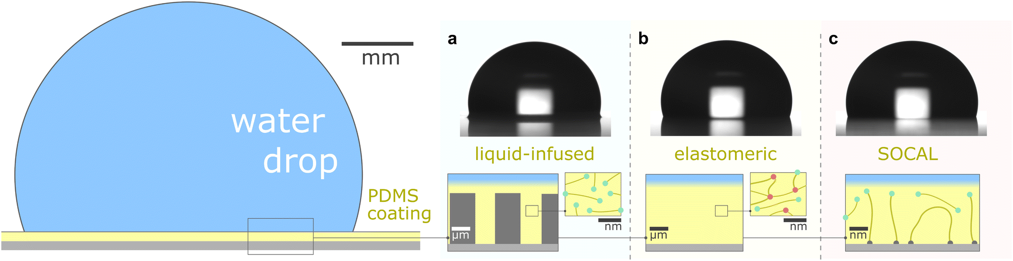 | ||
| Fig. 1 PDMS surface with sessile water drop. Scale bars serve as order of magnitude guide. Depending on their molecular chain configuration and substrate arrangement, PDMS surfaces can be (a) liquid-infused, (b) elastomeric, or (c) molecularly attached (SOCAL) to a rigid substrate. The thickness of the surface varies from mm and μm (LIS, elastomeric) to nm (in particular SOCAL). Top row shows shadowgraphs of sessile drops (10 ml) on each PDMS surface type, each exhibiting θ > 90°. (a) Low molecular weight chains with free ends (green points) behave as a Newtonian liquid, obtaining viscosities between 1 mPa s ≤ η ≤ 10 kPa s. Rough/porous solid substrate texture provides support for oil lubrication and increases surface retention. (b) Crosslinks (red points) create a network mesh with elasticity. Free chains (PDMS oil) can reside inside the network and rearrange freely. The degree of crosslinking and the amount of free chains inside the network determine the softness and lubrication of elastomer surfaces. (c) PDMS chains are covalently bonded to anchor sites (gray points). The free ends remain flexible and maintain liquid-like surface properties on SOCAL surfaces. Few chains are grafted on both chain ends to the surface. Illustration and shadowgraphs adapted from ref. 65. | ||
After establishing the structural differences in chain–chain and chain–surface organization on the different surfaces, we discuss their characteristic wetting behavior. We consider static and dynamic wetting – with a particular focus on the wetting ridge. This feature is ubiquitous amongst PDMS-based surfaces and the most pivotal element for wetting,66–72 drop mobility,66,71,73–77 and surface durability.46,78–83 Contact friction mostly dissipates in the ridge.74,75,84–86 Therefore it is critical for lubrication and drop sliding. However, it also accumulates surface material, and contacting objects may entrain surface material in the wetting ridge.87 Eventually, this can cause surface deterioration and malfunction. We discuss secondary effects such as PDMS-drop cloaking88–90 which influences the wetting behavior and surface durability.
We emphasize the importance of the surface-associated wetting properties as they are directly related to lubrication and durability: these are the two main concepts for optimized surface functionality. This perspective will help to gain a generalized, fundamental understanding of these most important PDMS-based surface variants, which helps to create guidelines for optimized and long-lasting PDMS surfaces.
2 PDMS-based surface – structure and properties
PDMS-based surfaces come in various configurations with associated material properties and wetting behaviors. We consider three common types of PDMS-based surfaces, (i) PDMS oil-based surfaces (e.g., liquid-infused surfaces), Fig. 1a, (ii) PDMS elastomeric surfaces (e.g., crosslinked polymers), Fig. 1b, and (iii) PDMS SOCAL surfaces (e.g., liquid-like polymer chains), Fig. 1c. Each PDMS-based surface has the same monomeric building block, and consequently, some intrinsic properties are shared among the surface types.The monomer of PDMS has an inorganic siloxane backbone and two methyl side chains, Fig. 2a center. The silicon-based backbone sets it apart from alkyl (hydrocarbon) or perfluoroalkyl (fluorocarbon) chemistries, hence the classification of siloxanes (silicon–oxygen bond).
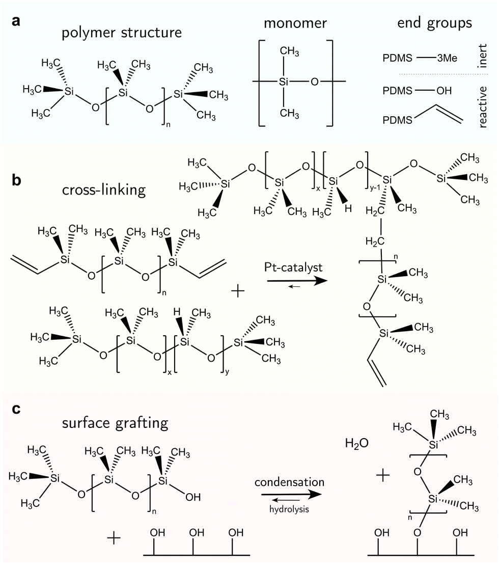 | ||
| Fig. 2 Chemical structure of polydimethylsiloxane. (a) PDMS can be oligomeric (n < 100) with low viscosity (1–5 mPa s) or assemble into long chains with high viscosities (up to η = 10 kPa s). The silicon–oxygen backbone provides chain flexibility while the methyl side chains yield water repellency. The end groups can be inert (trimethylsilyl) or reactive (hydroxyl, vinyl). (b) Hydrosilylation reaction between linear vynil-terminated PDMS chains (top) and cross-linking agents with methylhydrosiloxane monomers create branches and networked elastomeric polymers. Here, the cross-linking agent is a polymer chain with x dimethylsiloxane and y methylhydrosiloxane monomers that are randomly arranged. The network branches are randomly distributed on the cross-linker chain and terminal on the PDMS base chain. (c) Hydroxyl-terminated PDMS chains can be grafted on surface hydroxyl groups that naturally occur on metals/metalloid oxides, or can be functionalized with hydrogen plasma. | ||
The siloxane backbone is more flexible than a carbon backbone. This flexibility is attributed to the large Si–O–Si bond angle of 143°–150°64,91,92 which separates the pendant dimethyl groups. In addition, the alternating oxygen atoms do not allow side groups, resulting in low rotational energy around the backbone (3.3 kJ mol−1) – e.g., lower than what is noted between carbon–carbon bonds with methylene CH2 configurations (13.8 kJ mol−1) that typically occur in comparable organic polymers, such as polyethylene glycol.93 As a result, PDMS chains are highly flexible, and readily re-orientate to a minimal energy state, while possessing a low glass transition temperature (≈−150 °C).94
The organic content in PDMS is relatively low compared to other silicones due to the small organic methyl group (CH3, is the smallest organic group). The apolarity of the methyl group yields weak interactions with polar solvents such as water and alcohols.95,96 This is reflected in the low solubility which, in the case of water, is only ≈770 ppm.97–99Vice versa, PDMS is even insoluble in water.31 The poor interaction strength between PDMS and water, however, does not hamper the diffusive mobility of H2O molecules in PDMS (≈2 × 10⁻⁹ m2 s−1)99,100 and is comparable with many other liquid–liquid diffusivities.
The weak interaction strength with many solvents40 results in low PDMS surface energy. Consequently, adhesion between contacting liquids and PDMS is relatively weak. Water repels from PDMS surfaces as reflected in the contact angles ranging between 90°–110°.101–106 The flexibility of PDMS chains maintains slippage and thus provides mobility for contacting drops.107–110 Depending on the surface type, aqueous and organic drops can slide off when tilting the surface by a few degrees. However, on some PDMS surfaces drops remain pinned even when tilting the surface by 90°.
PDMS chains can be adjusted in length (i.e., molecular weight), cross-linkage, and chemical/physical surface attachments (“grafting”). Such variations shape distinctive surface types and features including viscosity, elasticity, film thickness, and durability.
2.1 Liquid-infused surfaces
The design of liquid-infused surfaces is to some extent nature-inspired: carnivorous plants such as the Nepenthes pitcher plant utilize a combination of leaf texture and lubrication (the plant uses water as a lubricant) to trap insects such as ants.111 Liquid-infused surfaces comprise a micro- or nanostructured texture, infiltrated with liquid PDMS oil, also termed silicone oil. Typically, silicone oils are PDMS chains terminated with trimethyl groups, Fig. 2a. The end groups are nonreactive; therefore PDMS remains liquid with a linear chain topology,13Fig. 2a, left. The oil viscosity is tunable via the number of monomer units in the chain and ranges from 1 mPa s to 10 kPa s.112 Short PDMS chains (“oligomers”113) with n < 100 monomer units are typically very mobile with low viscosities of η ≤ 50 mPa s. Due to the low surface tension of PDMS oils, almost all surfaces are “siliconephilic”, enabling rapid spreading of oil into the porous, micro-/nanostructure textures.114–116 Micro- and/or nanostructures are added to the surface to enable stronger oil retention by capillary forces.117 These surfaces are summarized under the surface class named “SLIPS” (slippery liquid-infused porous surface) or “LIS” (lubricant-infused surface).59,60 The oil provides lubrication, resulting in static friction forces orders of magnitude lower than dry friction. Most liquid drops slide off when tilting the surface by merely a few degrees. However, the infused oil can also be taken along, inducing degradation of the coating.Various strategies for oil replenishment,118 such as microfluidic setups119 or lubricant reservoirs120,121 have been implemented to enhance the lifetime of the surface.
2.2 Elastomeric surfaces
Crosslinked PDMS coated on substrates forms elastomeric surfaces, Fig. 1b. Vinyl- or hydroxyl-terminated PDMS chains (Fig. 2a, right) are reactive and widely used in cross-linking reactions. In Sylgard 184 (a commercial PDMS elastomer), these reactive PDMS chains are mixed with a platinum-catalyzed methylhydrogensiloxane, (HCH3)SiO, cross-linker. In a hydrosilylation reaction, these shorter siloxane-based cross-linker chains (n ≈ 10) undergo an addition reaction with the vinyl groups on the PDMS chain ends,122Fig. 2b. Other derivatives of the synthesis exist. For example, the vinyl group can become incorporated in the siloxane backbone or other cross-linking agents may be utilized to realize addition and condensation crosslinking-reactions.123–126The mixture of activated PDMS chains and cross-linker is coated on a surface by e.g., spin-coating, dip-coating, or blade-coating,127–129 before the reaction proceeds. Crosslinking reactions (independent of their formulation) will eventually arrive at the “gel point”. The gel point is achieved when a percolated bulk network forms and the material loses fluidity.130 Physically, this is an equilibrium state where the original PDMS liquid mixture becomes a soft solid (i.e., a gel). Three specific changes to physicochemical properties arise. (i) Thermal rheology; as with other thermoset polymers, once a PDMS elastomer reaches the gel point, it can no longer reflow upon heating (unlike thermoplastics). This occurs above the glass transition temperature (or even melting point) of an equivalent linear (identical Mw, uncrosslinked) PDMS chain. (ii) Solvation; prior to gelation, the PDMS liquid mixture is readily soluble in certain solvents (e.g., hexane or toluene95). However, post-gelation, cross-linked PDMS will experience swelling instead. The cross-links preserve the integrity of the elastomeric polymer network. (iii) Mechanical; passing the gel point induces an abrupt increase of the viscosity and the emergence of elasticity.131 Depending on the cross-linker to oligomer ratio, the material obtains a stiffness between 1 kPa and 10 MPa.105,132–135
Even under optimal stoichiometric conditions, not all reactive chains will be crosslinked to the network.95 At least 3% of the chains will remain free within the network.95 These free chains alter the material properties. They can accumulate at the coating surface towards air and in the wetting ridge136 where they separate from the network.80,82 This has consequences for static and dynamic wetting.46,79,83
2.3 SOCAL surfaces
The free chain ends of PDMS can be covalently anchored to a surface, creating a nanometer-thin coating,137–141Fig. 1c. Most chains are anchored at one end while the other remains free. Few chains can be grafted on both ends, forming chain loops.142,143 The free-moving end is almost as flexible as liquid oligomers or oils and the surface interface is comparably slippery. Therefore, these surfaces are often called “liquid-like” or “SOCAL” (slippery, omniphobic, covalently attached, liquid) surfaces.Surface anchoring is done either by a “grafting-from” or a “grafting-to” reaction. “Grafting-from” implies that chain polymerization is initiated at the anchor site on the surface and proceeds by adding PDMS monomer units. In a “grafting-to” reaction, an already polymerized chain binds to the surface.137,138,144,145 “Grafting-from” can be attained by e.g., highly reactive chloro-terminated siloxanes (monomers or oligomers). Long PDMS chains (n > 1000) will experience “grafting-to” anchoring. In both instances, they are reported to form covalent bonds and create molecularly thin layers.146
Surface anchor sites are typically provided by hydroxyl groups, Fig. 2c. Anchor sites can be created using chemical treatment, e.g., oxygen plasma exposure or alkali activation.147 Many metals/metalloid oxides (e.g., SiO2, TiO2, Al2O3, NiO) naturally form hydroxyl groups under ambient water vapor exposure.148 Water dissociates on surfaces if acids (e.g. hydrofluoric acid) or alkali (e.g. sodium hydroxide) are used. Spontaneous dissociation of water on metal surfaces has also been reported,149,150 alongside the spontaneous scission of covalent bonds in long PDMS chains.137
Grafted PDMS chains exist in a stretched or a collapsed state, depending on the affinity to the surrounding solvent and the chain density.151 Polar liquids (i.e., water) collapse chains as hydrophobic aggregation occurs to minimize surface energy. Organic liquids can stretch out chains if they are preferably solvated under similar chemical affinity. Anchored chains swell when exposed to PDMS oil. These solvent-dependent chain conformations lead to unique wetting behaviors: while both advancing θa and receding angles θr follow trends expected by surface tension variations (i.e., high for water, low for organic liquid), contact angle hysteresis Δθ = θa − θr is low for both liquids.152,153 This is attributed to the nanometric smoothness of such surfaces and the flexibility exhibited by grafted chains. At the molecular level, grafted chains rotate almost freely, reducing contact friction154 Thus, contact angle hysteresis Δθ remains relatively low. Notably, Δθ depends on the grafting density and grafted chain length (i.e., the molecular weight).144 For example, Δθ was measured to be lower on SOCAL surfaces with 6 kDa chains, compared to both shorter (0.77 kDa) and longer (117 kDa) chains.137
3 Soft wetting mechanisms
3.1 Static wetting ridge
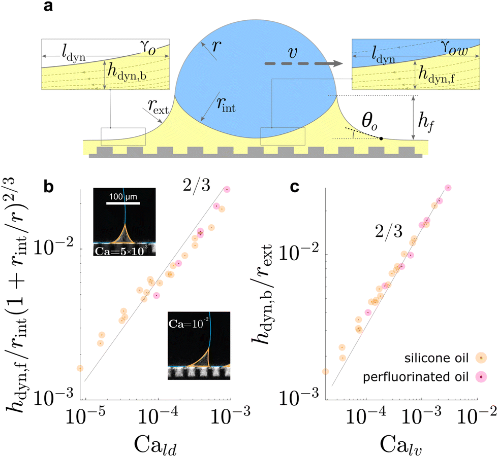
All surface types share the formation of an annular wetting ridge around the three-phase contact line.58,155–157 The wetting ridge is defined as the region that rises above the original unperturbed level of the surface. On liquid-infused surfaces, the wetting ridge consists of PDMS oil only,118,158,159 whereas on elastomers, it may consist of a mixture of crosslinked and liquid PDMS, depending on the swelling ratio.80,82 On SOCAL surfaces, the wetting ridge will encompass the local stretching of the grafted polymer chains.160,161 As PDMS chains are organized differently on the liquid-infused, elastomer, and SOCAL surfaces, the material forces in the wetting ridge differ, as well. Thus, each surface type forms a characteristic wetting ridge with a specific geometry. The wetting ridge significantly contributes to the overall drop morphology and the wetting dynamics.Oil depletion is already triggered by contacting water drops that induce the formation of annular wetting ridges, Fig. 3a. Wetting ridges formed on lubricant-infused surfaces can be visible to the naked eye, Fig. 1a. Still, the characteristic sizes are usually in the micro-domain (ca. 200 mm), and optical magnification helps to reveal more detail, Fig. 3a right.
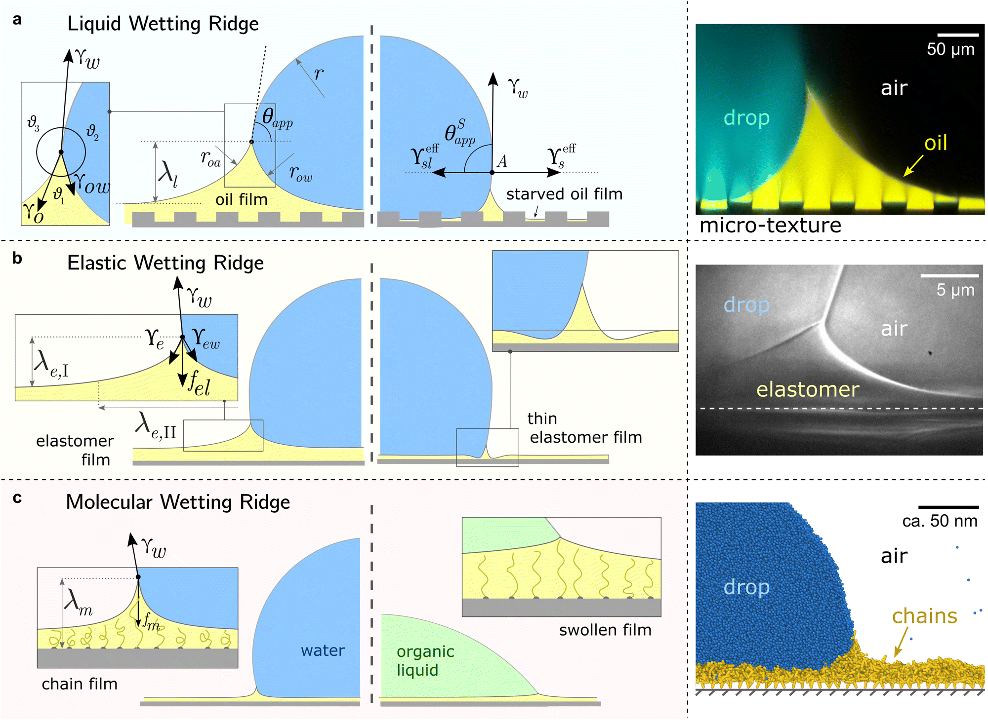 | ||
| Fig. 3 Different manifestations of the wetting ridge on different PDMS surfaces. (a) Liquid wetting ridge on a liquid-infused surface. Neumann balance at the three-phase contact line (box) and the apparent contact angle θapp. The right half illustrates the starved limit and the pseudo-Young's balance. Macroscopically, the origin of the surface tension vectors (point A) aligns with the substrate baseline. The image on the right shows a liquid wetting ridge, taken with a fluorescence confocal microscope, adapted from ref. 118. (b) Elastic wetting ridge on an elastomeric surface. Bulk elasticity creates a compliance force fel ∝ Gλe,I, resulting in wetting ridges smaller than the liquid ones. The right half shows material dimpling around the wetting ridge when the surface coating is very thin. The right image shows an elastic wetting ridge, taken with an X-ray microscope on elastomeric PDMS (3 kPa), adapted from ref. 164. (c) Molecular wetting ridge on a SOCAL surface. The entropic force of the PDMS chain fm limits the surface tension-induced chain stretch. Right half shows surface swelling when liquid-PDMS affinity/solubility is high. The right image shows a molecular wetting ridge, computed with coarse-grained molecular dynamics simulation, adapted from ref. 89. | ||
For drops smaller than the capillary length, gravity can be neglected and capillary interactions between the lubricant and the water drop solely govern the morphology of the wetting ridge. In contrast to wetting on inert rigid surfaces, a single angle, such as the Young angle,165 is insufficient for this wetting configuration.166 On soft surfaces, the surface material (the lubricant) adapts to the wetting drop as the interfacial tension of the drop pulls on the surface. The surface becomes curved in the vicinity of the wetting ridge. In equilibrium, the (liquid) wetting ridge is in a so-called “Neumann configuration”, which implies a balance of the three fluid interfacial tensions [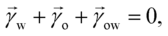 subscripts correspond water–ambient, oil–ambient, and oil–water], Fig. 3a left box. This tension balance yields a closed triangle, characterized by the threeassociated Neumann angles ϑ1, ϑ2, and ϑ3.167 The angles are related to the interfacial tensions as
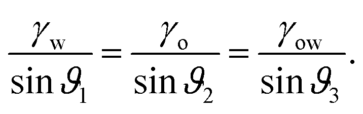 | (1) |
While the classical Young equation/angle fails for lubricant-infused surfaces, a similar angle can be recovered in the limit when the wetting ridge is small compared to the size of the drop, Fig. 3a center. This limit typically prevails in the “starved limit” when the infused PDMS oil is scarce. The resulting “pseudo Young angle” θSapp![[thin space (1/6-em)]](https://www.rsc.org/images/entities/char_2009.gif) 172 is
172 is
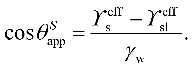 | (2) |
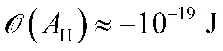
Moreover, in the starved limit, the shape of the wetting ridge is not only defined by capillarity. Disjoining pressures must also be considered when the oil film becomes very thin (<≈100 nm) because the oil–ambient interface starts to interact with the oil–solid interface.173 Such interactions are characteristic of very thin films and are summarised in the “disjoining pressure” framework.173 The interactions take place on a molecular level and can stem from a combination of van der Waals interactions, electrostatic attraction or repulsion, and steric forces.174 For static PDMS oil films, the interactions are usually purely dispersive, and the disjoining pressure is
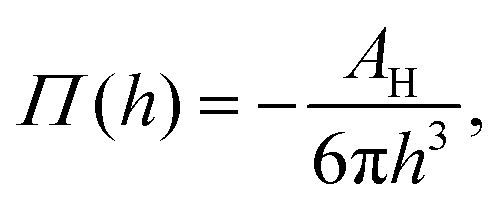 | (3) |
 (cf. ref. 176 for a comprehensive material list). In case of severe film starvation, the disjoining pressure needs to be considered within the total free energy.72 A consequence is that the oil interface assumes shapes, different from the catenoid.169
When the surface holds sufficient PDMS oil, the contact angle defined in eqn (2) breaks down because the assumption of a small wetting ridge no longer holds. The interface of the ridge now contributes to the total free energy. It becomes challenging to define a baseline from which to measure the (pseudo) angle, as the wetting ridge conceals the footprint of the drop. In practice, apparent contact angles θapp are utilized, which are defined as the angle of the drop at the Neumann point to the horizontal plane, Fig. 3a left. The size of the large ridge λl and the size of the drop r are related to the difference between θapp and θSapp68 per
| λl = r(cosθapp − cosθSapp). | (4) |
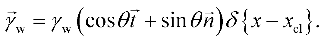
The shape of the elastic wetting ridge can be found by balancing the bulk elasticity and the surface stress of the network to the imposed surface tension of the water drop at the three-phase contact line. The surface tension of the water pulls on the surface, acting like a point/line load on the PDMS material, reading
 | (5) |
![[n with combining right harpoon above (vector)]](https://www.rsc.org/images/entities/i_char_006e_20d1.gif) and
and ![[t with combining right harpoon above (vector)]](https://www.rsc.org/images/entities/i_char_0074_20d1.gif) denote the surface normal and tangential vectors respectively. δ{x − xcl} denotes the Dirac delta function and xcl localizes the horizontal position of the three-phase contact line. The surface stress balance is then
denote the surface normal and tangential vectors respectively. δ{x − xcl} denotes the Dirac delta function and xcl localizes the horizontal position of the three-phase contact line. The surface stress balance is then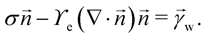 | (6) |
 | (7) |
Solutions of this system of equations (and variations) show that the competition between the bulk elasticity (G) and the capillary point load (γwsinθ) produces shapes that are comparable with experimental measurements.164
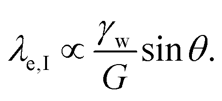
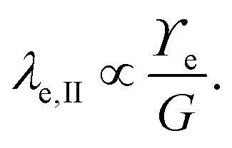
Considering only these two components, however, produces a singularity at the contact point of the load. The surface tension of the network material ϒe regularizes this singularity by opposing the deformation with plastic stresses.166,181 The length scale at which the surface tension-regularization emerges is
 | (8) |
 is below
  the Neumann configuration [eqn (1)] is recovered. The ratio of the two elastic length scales the strain [ε = λe,I/λe,II] and demarcates the two limits in which the stress can be treated:
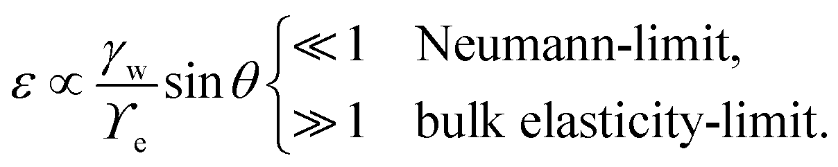 | (9) |
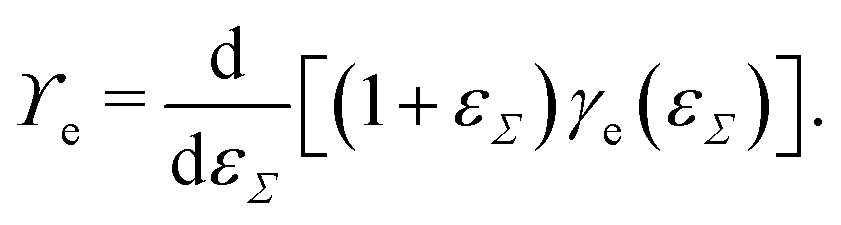
Straining solid (crystalline) surfaces can alter the molecular surface structure, yielding a local dependency of the surface energy on the strain.182 Consequently, the surface energy and the surface tension are not equal [γe ≠ ϒe]. The surface energy is a function of the surface strain γe(εΣ), and the relation to the surface tension is
 | (10) |
Further experimental findings indicate that the surface tension might not only depend on strain [per eqn (10)] but on the strain rate, which could be interpreted as a form of complex surface rheology.194
The molecular wetting ridge is, again, a result of the interplay of the capillary forces induced by the wetting drop and the material response of the surface. However, the motivation of the linear elasticity framework from a continuum mechanical point of view is less obvious as the length scales are much smaller. Since water is a poor solvent for PDMS,97–99 the grafted chains are in a collapsed state, underneath the drop, Fig. 3c left box. Deformations occur (at most) over the length of a chain (collapsed to stretched) in contrast to elastomers that undergo deformations far exceeding the lengthscales of the spacing between crosslinking nodes. Organic solvents are much better solvents40 and enable chain stretching, leading to smaller wetting ridges, Fig. 3 center box. Further, the chain configuration introduces isotropy as the chains are not laterally reticulated. Therefore, the ridge deformation on SOCAL surfaces is usually considered in a thermodynamic framework of the individual polymer chains. The restoring force on the molecular chain level originates from entropy.61 Stretched chains have a reduced conformational state. Thus, the entropy is low. This state is undesirable for the grafted chain. It strives to increase the possible conformations and maximize its entropy by recovering the unstretched state.196,197 Notably, the thermodynamic consideration for a swollen chain recovers a linear relation between the deformation and the restoring force per chain
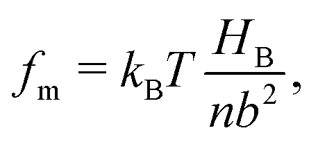 | (11) |
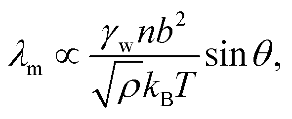 | (12) |
3.2 Free chains, cloaking, and swelling
:1 base to crosslinker), around 5%wt of the chains remain free. Free chains can be considered as a solvent that swells the crosslinked network.95,198,199 The volume ratio between the swollen network and the dry network defines the swelling ratio Q = Vswollen/Vdry. Depending on the degree of crosslinking, PDMS elastomers display different swelling ratios in equilibrium. For example, a gel prepared with Sylgard 184 with a 60:1 mixing ratio can be swollen up to Q ≈ 16 with low molecular weight (oligomeric) PDMS chains.82
Synersis – i.e., the extraction of free chains from the network onto the surface35,200–202 – can cause lubrication.79 This essentially makes (swollen) PDMS elastomers similar to liquid-infused surfaces on which contaminants (such as water) hardly stick.31
Synersis is typically induced by global effects such as temperature variations203 or the progression of the crosslink reaction,35 affecting the entire surface of the PDMS elastomer. Wetting drops, however, trigger the accumulation of free chains locally around the three-phase contact line, caused by the surface tension of the drop.46,78 On highly swollen PDMS elastomers, this can lead to the phase separation of free chains at the tip of the wetting ridge.80,82 The extent of phase-separation (measured by the size of the separated tip, hoil) is proportional to the swelling ratio Q, i.e., the number of free chains in the gel. On PDMS-based SOCAL surfaces, such kinds of phase-separated tips have also been observed in molecular dynamics simulations.89 Due to the small length scales of the surface, direct experimental visualization is still lacking.
| S = γw − γow − γo ≤ 0. | (13) |
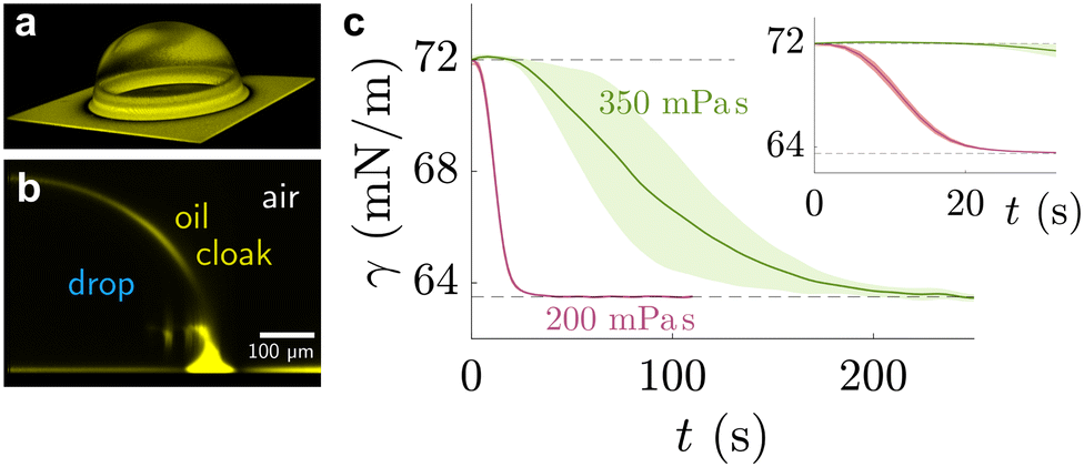 | ||
| Fig. 4 Sessile drop on lubricated surface, cloaked by PDMS oil. (a) Three-dimensional view of PDMS oil on the drop, obtained by laser scanning confocal microscopy. (b) Side view of the angular averaged 3D stack. Images adapted from ref. 89 (c) temporal evolution of pendant drop on PDMS elastomer with swollen with 200 mPa s (red) and 350 mPa s (green) PDMS oil. The shaded region shows the standard deviation of experimental repeats. Data adapted from ref. 207. | ||
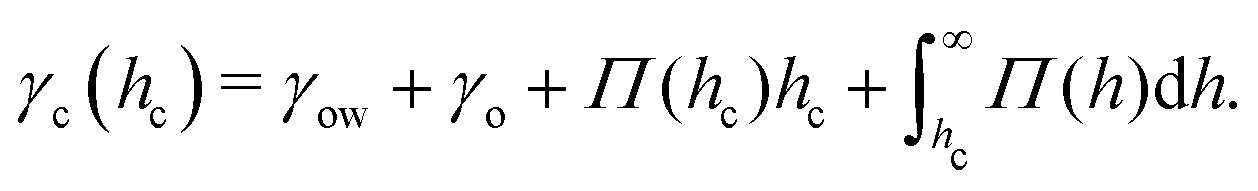
Naively, the “cloaked” surface tension γc of the drop effectively sums up from two interfaces (water–oil and oil–air) that replaces the uncloaked surface (water–air), i.e., γc = γow + γo. However, the concepts of surface tension and surface energy consider shared surfaces of two bulk phases. Surface tension and energy result from excess energy that decays at some length scale towards the bulk phases.208 The length (or the vicinity) in which the excess energy decays is also reflected in the stress isotropy, being isotropic in the bulk phases, and anisotropic near the interface.209 Following this reasoning, γc is only the sum of γow and γo when the cloaking layer is thick enough and the surface tension has “bulk properties”. However, the layer can be substantially thinner, especially upon cloak formation.52 In this case, the two interfaces (water–oil and oil–ambient) of the thin cloak layer start to interact with each other via the disjoining pressure Π(hc) yielding stabilizing stress contributions which depend on the thickness of the cloak hc. The stabilizing disjoining pressure contribution adds to the surface tension of the cloak with210–212
 | (14) |
When the wetting drop moves, the swelling kinetics can compete with the sliding of the drop. This leads to a steady state where the degree of swelling is not equilibrated but depends on the sliding speed of the drop. In this state, the surface underneath the front and rear of the drop swell to different degrees, and the PDMS wettability exhibits local gradients. This induces a contact angle hysteresis that does not depend on the surface inhomogeneity but the swelling kinetics, the drop size, and the sliding speed.43
3.3 Dynamic wetting ridge
 | ||
| Fig. 5 Dynamic geometries of liquid wetting ridge during drop sliding. The oil film underneath the drop and behind the drop, both, resemble a Landau Levich Derjaguin film. The dynamic film thickness (a) underneath the drop front hdyn,f, and (b) behind the drop rear end hdyn,b, both display the scaling ∝ Ca2/3, characteristic for Landau Levich Derjaguin films. Data in (b) and (c) adapted from ref. 52 and insets in (b) adapted from ref. 75. | ||
In general, the dissipation 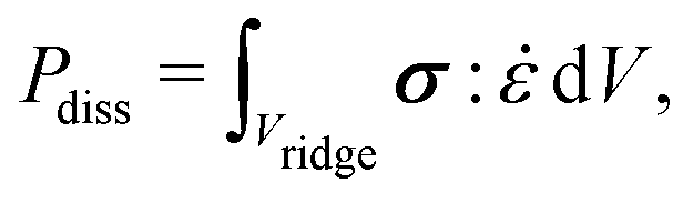 depends on the volume of the wetting ridge Vridge, the strain rate
 ![[small epsi, Greek, dot above]](https://www.rsc.org/images/entities/i_char_e0a1.gif) (i.e., the rate of reorganization), and the material stress σ. The stress in the wetting ridge follows from material laws, and thus, changes with the fabric of the different surface types. PDMS oils with η < 20 Pa s are Newtonian fluids that show a linear relationship between stress and shear rate, σ = η. If the oil is very viscous it can exhibit shear-thinning behavior,216 however, the drop mobility is significantly hampered in the Newtonian low-speed regime.75,85 Still, lubrication enables higher drop mobility on lubricated compared to non-lubricated surfaces which tend to be rougher and have a much larger number of surface defects that slow down the drop.26 The shear stress in the liquid wetting ridge scales as σ ∝ ηv/hr. The dissipation rate is found by integrating the viscous stress over the ridge area. Furthermore, we must account for the variation of dynamic contact angle of the wetting ridge with speed, Fig. 5(b) and (c), which leads to, Pdiss ∝ vβϕr(ηv/θo). ϕ accounts for the texture density which is important as only texture contacts along the perimeter add to the overall friction. On parts where the ridge contacts oil, it is assumed that no significant shear builds up and can, therefore, be neglected. β = ln(hr/α) and α ≈ 100 nm account for a cut-off length.217θo is the opening angle, formed between the horizontal plane and the wetting ridge. This angle changes with the speed according to Tanner's law θo ≈ (βηv/γ)1/3.218 Including Tanner's law into the expression for the dissipative power yields Pdiss ∝ vϕr(βηv/γ)2/3. The ratio between the viscous stress and the surface force in the liquid wetting ridge are condensed in the capillary number Ca = ηv/γ. Hence, the dissipative scaling can be written compactly as
(i.e., the rate of reorganization), and the material stress σ. The stress in the wetting ridge follows from material laws, and thus, changes with the fabric of the different surface types. PDMS oils with η < 20 Pa s are Newtonian fluids that show a linear relationship between stress and shear rate, σ = η. If the oil is very viscous it can exhibit shear-thinning behavior,216 however, the drop mobility is significantly hampered in the Newtonian low-speed regime.75,85 Still, lubrication enables higher drop mobility on lubricated compared to non-lubricated surfaces which tend to be rougher and have a much larger number of surface defects that slow down the drop.26 The shear stress in the liquid wetting ridge scales as σ ∝ ηv/hr. The dissipation rate is found by integrating the viscous stress over the ridge area. Furthermore, we must account for the variation of dynamic contact angle of the wetting ridge with speed, Fig. 5(b) and (c), which leads to, Pdiss ∝ vβϕr(ηv/θo). ϕ accounts for the texture density which is important as only texture contacts along the perimeter add to the overall friction. On parts where the ridge contacts oil, it is assumed that no significant shear builds up and can, therefore, be neglected. β = ln(hr/α) and α ≈ 100 nm account for a cut-off length.217θo is the opening angle, formed between the horizontal plane and the wetting ridge. This angle changes with the speed according to Tanner's law θo ≈ (βηv/γ)1/3.218 Including Tanner's law into the expression for the dissipative power yields Pdiss ∝ vϕr(βηv/γ)2/3. The ratio between the viscous stress and the surface force in the liquid wetting ridge are condensed in the capillary number Ca = ηv/γ. Hence, the dissipative scaling can be written compactly as
| Pvis,Idiss ∝ ϕvr(βCa)2/3. | (15) |
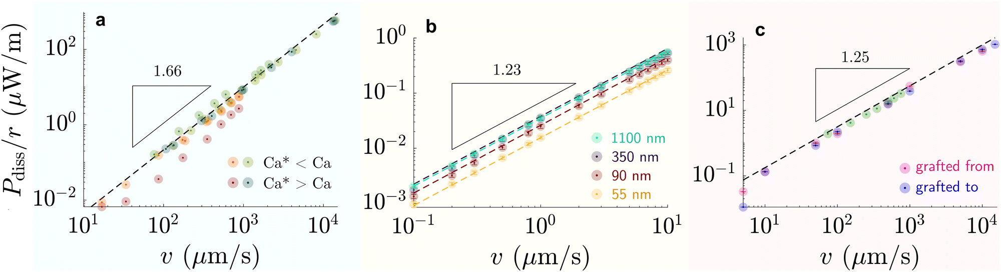 | ||
| Fig. 6 Dissipation-speed profile (Pdiss/r ∝ vk) on (a) liquid-infused silicone oil (green) η = 100 mPa s and perfluorinated oil (red) η = 30 mPa s (k ≈ 1.66), (b) G = 250 kPa elastomer (k ≈ 1.23), and (c) 6 kDa chain SOCAL surfaces (k ≈ 1.25). (a) Bright colors correspond to cases where Ca* < Ca and dark colors to cases where Ca* > Ca, with Ca* = (hp/r)3/2. (b) The colors correspond to various coating thicknesses: green – 1100 nm, blackberry – 350 nm, red – 90 nm, yellow – 55 nm. (c) Data points were measured on SOCAL surface, with chains: pink – grafted from, blue – grafted to substrate (cf. PDMS based surfaces – structure and properties). Data reproduced from (a) red84 green,75,85 (b),77 and (c) green219 rest.220 | ||
On flat lubricated surfaces, the ridge meniscus behaves analogously to a Landau Levich Derjaguin film: the viscous stress elevates the film in the vicinity ldyn behind the advancing and the receding wetting ridge.84,221 The elevated height scales as hdyn ∝ rCa2/3, and the vicinity length as ldyn ∝ rCa1/3. Depending on whether considering the advancing or receding ridge, Ca is formed with γow and γo, respectively. As many oil surfaces utilize a porous structure to maintain better retention of the oil film, hdyn only forms when this height exceeds the height of the porous structure hp.116 Combining the dynamic hdyn scaling with this inequality, produces the critical capillary number Ca* = (hp/r)3/2 that needs to be exceeded to form hdyn.85 The associated (secondary) dissipation rate within this domain scales (non-linearly in v, Fig. 6a) as
| Pvis,IIdiss ∝ γvrCa2/3. | (16) |
At high capillary numbers (Ca > ≈10−2), a different scaling law was observed between friction on velocity, with a lower exponent on the velocity. In this regime, drops begin to move more rapidly. The mechanism for this regime is still unknown. A tentative explanation that has been proposed is that the wetting ridge shape does not have time to fully develop in this regime.222
![[small epsi, Greek, dot above]](https://www.rsc.org/images/entities/char_e0a1.gif) ∝ εω. Together with the volumetric scaling V ∝ λe,I2, the dissipative work in the viscoelastic wetting ridge scales as
∝ εω. Together with the volumetric scaling V ∝ λe,I2, the dissipative work in the viscoelastic wetting ridge scales as| Pveldiss ∝ γwvrε2Came, | (17) |
Wetting ridge relaxations that are different from expected viscoelastic materials were observed on PDMS elastomers having free oligomer chains.228 The reorganization of the free chains inside the elastomer follows poroelastic behavior, which is typically slower than viscoelastic dissipation.229 Wetting ridges that move slowly dissipate energy in a different mode, as the material fabric can change significantly inside the ridge. As discussed earlier, a phase of pure liquid can form at the tip of the ridge where the dissipative picture resembles the liquid-infused case. The amount of phase separation scales inversely with the moving speed of the ridge.83 Thus, a complex back coupling between speed and dissipation is expected. While concise models for dissipation on swollen PDMS elastomers are missing, first clues suggest that the separation lowers dissipation: the accumulated oligomeric free chains have low viscosity and lubricate the drop and effectively reduce contact friction.46,79
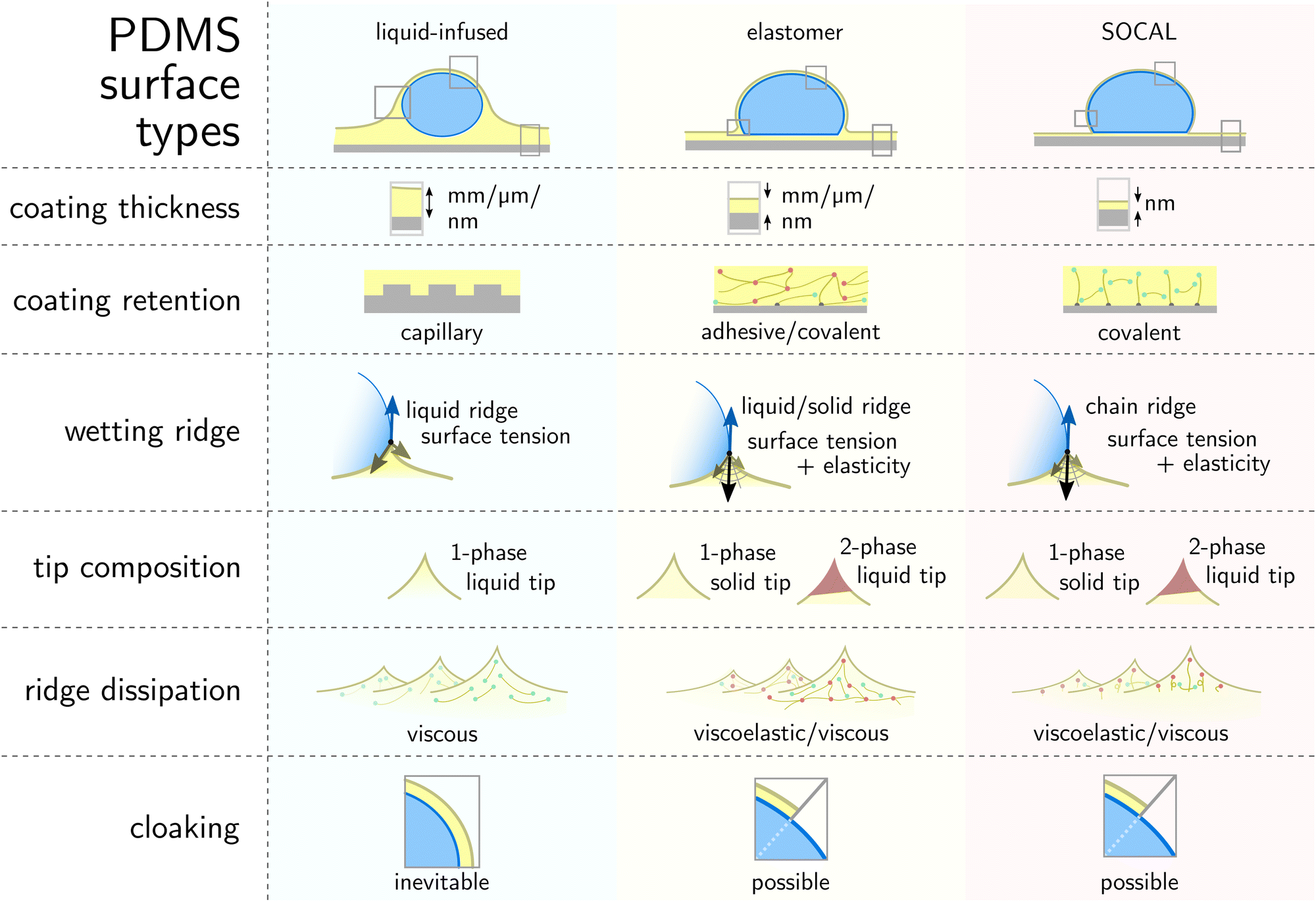
4 Coating comparison
In this review, we discussed wetting behaviors on PDMS-based surfaces. We discuss how this relatively simple polymer can create a wide design space for surfaces, via polymer-chain configurations, polymerization, and surface anchoring. The complexity in surface manufacturing varies for different surface variants: creating liquid-infused surfaces without a micro-/nanometric texture is straightforward. It can be achieved by simply spreading PDMS oil on a surface. The process is equally facile for PDMS elastomeric surfaces, but only if no special requirements regarding the coating thickness exist. The “grafting-from” technique for SOCAL surfaces requires a more elaborate process such as “chemical-vapor-deposition” (CVD), requiring controlled atmosphere conditions, and sometimes toxic chemicals (e.g. chlorosilanes or alkoxysilanes).The various surface designs open up a wide variety of concepts and mechanisms. Today, they are increasingly utilized and tuned for a plethora of applications. While similar at first glance, wetting mechanisms such as the wetting ridge develop differently on each PDMS-based surface variant. In the context of a specific application, this brings advantages and disadvantages. For example, self-cleaning is increasingly essential for preserving the energy efficiency of solar panels, bio-contamination reduction of medical equipment, or repelling stains and dirt on outdoor equipment and textiles. For this, all three PDMS-based surface variants are conceptually suitable as they strive to provide drop mobility (low static friction), a feature that is essential for self-cleaning.
Liquid-infused surfaces have freely flowing PDMS oils providing excellent lubrication properties and high drop mobility. An important avenue for future research is to understand how particulate contaminants adhere to the lubricant layer and whether they enter the solid crevices. However, one limitation of liquid-infused surfaces is that lubricant is depleted by the (comparatively) large wetting ridge when they are exposed to harsh environments. Thus, to make these surfaces viable for technological applications, further work is needed to systematically understand the mechanisms of lubricant depletion. Elastomer surfaces, on the other hand, have good material retention and hence mechanical durability, provided by the crosslink network. This advantage, however, brings along higher dissipation margins and declined drop mobility. SOCAL surfaces seem to overcome both challenges, as retention is high due to covalent surface anchors, while dissipation remains low, although not as low as liquid-infused surfaces. This is attributed to a minuscule ridge and the inherent flexibility of molecularly anchored chains that behave in a liquid-like manner. Particulate matter hardly sticks and can be removed easily. However, once the surface experiences critical damage, the nano-thickness of the SOCAL surface can be permanently abraded away. Bulky liquid-infused and elastomer surfaces provide plenty of surface material that – in case of surface damage – can self-heal and increase the surface lifetime (Fig. 7).
 | ||
| Fig. 7 Comparison of PDMS-based surface structures and wetting mechanisms on the three variants. Illustrations adapted from ref. 65. | ||
5 Open questions and perspectives
PDMS surfaces share several similarities regardless of whether they are in the form of elastomers, SOCALS, or LIS. The wetting ridge is a pivotal element in static and dynamic wetting on each PDMS-based surface type. This is remarkable, considering that the length scale of the wetting ridge can vary by several orders of magnitude and the (macro)molecular configurations can differ significantly between the different variants. It remains an open question whether a unifying model can be developed to describe the wetting dynamics on these different surfaces. To make progress on that front, future studies need to investigate the reorganization of PDMS (oily, crosslinked, or surface-grafted) and the associated dissipation in the dynamic wetting ridge in detail.The cloaking phenomenon has been observed experimentally on LIS and elastomeric surfaces. Yet, models for the dynamics of cloak formation remain lacking and it remains unknown whether the cloak influences the dissipation mechanisms. Even in equilibrium, the cloak bears an intriguing paradox for water drops: while the spreading coefficient suggests the formation of a stable cloak, dispersive van der Waals (vdW) interactions counterintuitively indicate an attractive disjoining pressure, leading to an unstable film. This paradox may be due to other stabilizing long-range forces (e.g. electrostatic). Further work is needed to understand under which conditions the cloak is stable and whether it influences the dissipation mechanisms. A few considerations and open questions are suggested here for the three types of surfaces.
• LIS – The PDMS oil in LIS is usually a homogenous, Newtonian, liquid, suggesting a simple design space of the surface. Yet, several methods exist to create the underlying solid substrate and to imbibe the lubricant, leading to a large zoo of LIS designs. Friction laws have been proposed for drops moving on LIS. Still, direct (experimental) validation of the dissipation mechanism in the wetting ridge remains lacking and it is still unclear whether and how the exact geometry of the solid substrate influences the dissipation mechanism. Depletion of lubricant over time remains the biggest challenge that needs to be tackled to design long-lasting PDMS surfaces. The wetting ridge and the cloak are significant causes of depletion when drops slide off lubricated surfaces. As both, the cloak and the wetting ridge originate from thermodynamic forces, avoiding their formation will be challenging. We still lack a quantitative understanding of how much lubricant is depleted per drop which slides off a LIS.
The prevalence of LIS in the domain of self-cleaning, shear-reduction, and biocompatible surfaces has shown great promise for use in consumable and biotechnological applications. The growth and incubation of cells in LIS surfaces could potentially provide microenvironments for single cell sorting and growth mediums. The unique hierarchical structures of LIS can provide high interfacial interactions for applications requiring cell growth, such as oxygenation or growth media replenishment.
• Elastomers – The elastomeric ridge is arguably the most complex, owing to the coupling between the liquid and crosslinked PDMS. No other PDMS surface possesses the same degrees of freedom in tunability: crosslink density and distribution of free chains, shear modulus, oil viscosity, oil chemistry, oil-to-network affinity, oil surface tension, and polymer network surface energy. We only recently started to understand the process of oil separation in the wetting ridge, but the consequences of and for sliding drops are still largely unexplored. This is especially evident from a theoretical point of view. What is the interplay between the oil and the crosslinked PDMS in the wetting ridge and how does it change during dynamic wetting? Even for a static scenario, it is still partially unclear what causes separation, or more importantly, what keeps the lubricant trapped inside the network. Answering these question is a key aspect of designing long-term stable elastomeric coatings.
The formation of cloaks and accumulation of ridges that are composed of PDMS oil remains one of the most severe degradation issues of PDMS-based surfaces. Swelling of PDMS elastomers with liquids that show much less interactions with wetting liquids (e.g. fluorinated oils) compared to PDMS oils (high spreading coefficients) may resolve or slow down the engineering challenge of separation, cloaking, and gradual surface degradation. Further investigation into the use of sustainable infusion liquids or network materials could help facilitate the future development of long-term functional and naturally degradable materials.
• SOCALS – Wetting ridges on SOCAL are inherently hard to image and investigate, due to the nanometric length scale. While state-of-the-art computation methods are providing a greater understanding of SOCAL surfaces, experimental validation is needed to validate the accuracy of these computational models. This is particularly challenging for water drops. Detailed experimental investigations suffer from the combination of the nanometric length scales and high surface curvatures around the three-phase contact line, caused by contact angles close to 90°. To obtain the required resolution, devices with higher sensitivity need to be developed. Alternatively, the problem can be approached using drops with lower liquid polarity, circumventing the challenges accompanied by high curvatures and contact angles. For nonpolar drops, nanometric analytical techniques such as interferometric microscopy (cf. Appendix – Methods and Techniques) might provide sufficient in-depth resolution to resolve the dynamic reorganization of the wetting ridge. A key goal would be to develop constitutive models to describe dissipation on SOCAL surfaces.
Tuning the silane chemistry on SOCAL surfaces may provide gradients or patterns in glass transition properties, thereby enabling temperature-sensitive surfaces. The use of PDMS may also help shield defects of other organic-material based surfaces owing to the “self-smoothing” nature of highly flexible siloxane chains. Co-integrating different surface chemistries may optimize chain flexibility, giving rise to multi-functional surfaces capable of next-generation easy-to-clean surfaces. Promising applications include on-land or floating photovoltaic applications. More intensive studies are needed to investigate their potential in particulate or dust removal while maintaining high energy throughput during operation.
We are currently observing a transition in the perspective of soft wetting research, shifting from a fundamental understanding to a focus on practical applications, encompassing fields such as energy and biomedical sciences. Overall, PDMS-based surfaces show superior UV-stability, combined with easy-to-clean performance. The integration of PDMS-based surfaces with other organic or inorganic materials may realize useful engineering concepts. For instance, in the emerging field of synthetic biology, PDMS-based microfluidic devices play a crucial role for the synthesis of a broad range of artificial cell precursors. The subsequent assembly of these complex building blocks in functional units remains an ambitious goal of synthetic chemists, physicists and biologists. Fully exploring the potential of PDMS-based surfaces may represent a pathway to improve the synthesis and assembly of cellular building blocks (membranes, proteins, cytoskeleton, etc.). Furthermore, the surface energy of PDMS is almost as low as that of environmentally harmful perfluoroalkyls. It may therefore serve as a viable replacement material for many electrode (i.e., Nafion) or membrane materials (i.e. PTFE-based) that are at the core of our energy-water infrastructure.
To utilize soft wetting effectively in any application, fundamental understanding is still critical, as illustrated in the self-cleaning context (cf. Coating comparison). This review serves to provide a series of guidelines that link the current state-of-the-art soft wetting knowledge – in particular on silicone surfaces – to mechanistic features desirable for a myriad of applications.
Data availability
No primary research results, software or code have been included and no new data were generated or analysed as part of this review.Conflicts of interest
The authors have no conflicts to disclose.Appendices
Appendix – methods and techniques
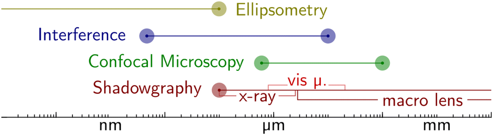 | ||
| Fig. 8 Different imaging techniques are suitable for different length scales. Most light-based techniques such as (visible) shadowgraphy or confocal microscopy are bound by the diffraction limit. Interferometry and ellipsometry overcome this limit by exploiting wave superposition and phase shifts, bringing down the resolution limit to sub-nano. | ||
Mechanical characterization
δ can be associated with damping.
 | ||
| Fig. 9 Force microscopic measurement conducted on a confocal microscope. Here, 10 μl water drops slide on SOCAL surfaces (cf.Fig. 6c). (a) Kymograph of the blade deflection upon drop contact, measured with the reflection channel of an xt-scan. (b) Calibration curve to determine the spring constant of the blade, here approx. 0.21 N m−1. (c) Atto-dyed, steady-state drop footprints, and faintly the probing metal blade. (d) overlay of various relaxed drop footprints. | ||
Computational methods
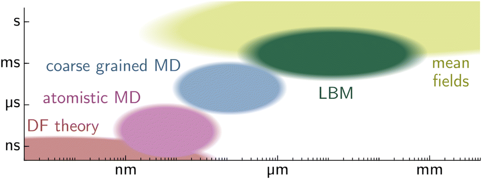 | ||
| Fig. 10 Typical time and length scale domains of wetting problems, treated with different computational methods. Density functional theory (DFT) is utilized in the sub-nano domain. The next larger domain sizes are treated with atomistic and coarse-grained molecular dynamics (MD) simulation. The Lattice Boltzmann method (LBM) utilizes kinetic theory and is mesoscopic, linking the microscopic and the macroscopic world. Mean field theory is utilized for large molecule ensembles and macroscopic problems. | ||
Acknowledgements
We wish to thank H.-J. Butt, Z. Cai, S. Karpitschka, F. Schmid, and P. Stephan for stimulating and helpful discussions. L. H. thanks T. J. Böddeker, R. L. Knorr, and K. Sporbeck for feedback on the manuscript. This research was motivated by the DFG Priority Programme 2171. Financial support came from the DFG Emmy Noether Programme No. 460056461 (L. H.), the EPSRC National Fellowship in Fluid Dynamics Grant No. EP-X028410-1 (A. N.), the DFG Graduate School RTG 2516 No. 405552959 (R. G. M. B.), the US National Science Foundation through CBET grant 2326933 (J. T. P.), the European Union's HORIZON research and innovation program under the Marie Sklodowska-Curie grant agreement No. 101062409 and the Academy of Finland grant agreement No. 13347247 (W. S. Y. W.), and the Max Planck Center for Complex Fluid Dynamics – University of Twente (D. V.).Notes and references
-
A. K. Bhowmick, Current Topics in Elastomers Research, CRC Press, Boca Raton, FL, 2008 Search PubMed
.
- L. G. Griffith, Acta Mater., 2000, 48, 263–277 CrossRef CAS
- R. Yoda, J. Biomater. Sci., Polym. Ed., 1998, 9, 561–626 CrossRef CAS PubMed
- J. A. Lim, F. Liu, S. Ferdous, M. Muthukumar and A. L. Briseno, Mater. Today, 2010, 13, 14–24 CrossRef CAS
-
N. C. Greenham and R. H. Friend, in Solid State Physics, ed. H. Ehrenreich and F. Spaepen, Academic Press, 1996, vol. 49, pp. 1–149 Search PubMed
- B. S. Lalia, V. Kochkodan, R. Hashaikeh and N. Hilal, Desalination, 2013, 326, 77–95 CrossRef CAS
- U. Eduok, O. Faye and J. Szpunar, Prog. Org. Coat., 2017, 111, 124–163 CrossRef CAS
- K. Golovin, A. Dhyani, M. D. Thouless and A. Tuteja, Science, 2019, 364, 371–375 CrossRef CAS PubMed
- P. Hu, Q. Xie, C. Ma and G. Zhang, Langmuir, 2020, 36, 2170–2183 CrossRef CAS PubMed
- D. C. Duffy, J. C. McDonald, O. J. A. Schueller and G. M. Whitesides, Anal. Chem., 1998, 70, 4974–4984 CrossRef CAS PubMed
- M. Maitz, Biosurface and Biotribology, 2015, 1, 161–176 CrossRef
- A. Victor, J. Ribeiro and F. S. Araújo, J. Mech. Eng. Biomech., 2019, 4(1), 1–9 CrossRef
-
H.-H. Moretto, M. Schulze and G. Wagner, Ullmann's Encyclopedia of Industrial Chemistry, Wiley-VCH Verlag GmbH & Co. KGaA, Wiley-VCH Verlag GmbH & Co. KGaA, Weinheim, Germany, 2000, p. 682 Search PubMed
-
M. Butts, J. Cella, C. D. Wood, G. Gillette, R. Kerboua, J. Leman, L. Lewis, S. Rubinsztajn, F. Schattenmann, J. Stein, D. Wicht, S. Rajaraman and J. Wengrovius, Kirk-Othmer Encyclopedia of Chemical Technology, John Wiley & Sons, Ltd, 2002 Search PubMed
- H. U. Chung, A. Y. Rwei, A. Hourlier-Fargette, S. Xu, K. Lee, E. C. Dunne, Z. Xie, C. Liu, A. Carlini, D. H. Kim, D. Ryu, E. Kulikova, J. Cao, I. C. Odland, K. B. Fields, B. Hopkins, A. Banks, C. Ogle, D. Grande, J. B. Park, J. Kim, M. Irie, H. Jang, J. Lee, Y. Park, J. Kim, H. H. Jo, H. Hahm, R. Avila, Y. Xu, M. Namkoong, J. W. Kwak, E. Suen, M. A. Paulus, R. J. Kim, B. V. Parsons, K. A. Human, S. S. Kim, M. Patel, W. Reuther, H. S. Kim, S. H. Lee, J. D. Leedle, Y. Yun, S. Rigali, T. Son, I. Jung, H. Arafa, V. R. Soundararajan, A. Ollech, A. Shukla, A. Bradley, M. Schau, C. M. Rand, L. E. Marsillio, Z. L. Harris, Y. Huang, A. Hamvas, A. S. Paller, D. E. Weese-Mayer, J. Y. Lee and J. A. Rogers, Nat. Med., 2020, 26, 418–429 CrossRef CAS PubMed
- S. Kim, B. Lee, J. T. Reeder, S. H. Seo, S.-U. Lee, A. Hourlier-Fargette, J. Shin, Y. Sekine, H. Jeong, Y. S. Oh, A. J. Aranyosi, S. P. Lee, J. B. Model, G. Lee, M.-H. Seo, S. S. Kwak, S. Jo, G. Park, S. Han, I. Park, H.-I. Jung, R. Ghaffari, J. Koo, P. V. Braun and J. A. Rogers, Proc. Natl. Acad. Sci. U. S. A., 2020, 117, 27906–27915 CrossRef CAS PubMed
- Y. Xia and G. M. Whitesides, Angew. Chem., Int. Ed., 1998, 37, 550–575 CrossRef CAS PubMed
- V. Ozbolat, M. Dey, B. Ayan, A. Povilianskas, M. C. Demirel and I. T. Ozbolat, ACS Biomater. Sci. Eng., 2018, 4, 682–693 CrossRef CAS PubMed
- G. G. Morbioli, N. C. Speller and A. M. Stockton, Anal. Chim. Acta, 2020, 1135, 150–174 CrossRef CAS PubMed
-
N. J. Fendinger, in Organosilicon Chemistry Set, ed. N. Auner and J. Weis, Wiley, 1st edn, 2005, pp. 626–638 Search PubMed
- N. S. Sarai, T. J. Fulton, R. L. O'Meara, K. E. Johnston, S. Brinkmann-Chen, R. R. Maar, R. E. Tecklenburg, J. M. Roberts, J. C. T. Reddel, D. E. Katsoulis and F. H. Arnold, Science, 2024, 383, 438–443 CrossRef CAS PubMed
- J. Klein, D. Perahia and S. Warburg, Nature, 1991, 352, 143–145 CrossRef CAS
- J. Klein, Annu. Rev. Mater. Sci., 1996, 26, 581–612 CrossRef CAS
- T. Kreer, Soft Matter, 2016, 12, 3479–3501 RSC
- J. Klein, Science, 2009, 323, 47–48 CrossRef CAS PubMed
- B. R. Solomon, K. S. Khalil and K. K. Varanasi, Langmuir, 2014, 30, 10970–10976 CrossRef CAS PubMed
- T. Lee, E. Charrault and C. Neto, Adv. Colloid Interface Sci., 2014, 210, 21–38 CrossRef CAS PubMed
- S. B. Subramanyam, K. Rykaczewski and K. K. Varanasi, Langmuir, 2013, 29, 13414–13418 CrossRef CAS PubMed
- P. Kim, T.-S. Wong, J. Alvarenga, M. J. Kreder, W. E. Adorno-Martinez and J. Aizenberg, ACS Nano, 2012, 6, 6569–6577 CrossRef CAS PubMed
- W. S. Y. Wong, K. I. Hegner, V. Donadei, L. Hauer, A. Naga and D. Vollmer, Nano Lett., 2020, 20, 8508–8515 CrossRef CAS PubMed
- S. Amini, S. Kolle, L. Petrone, O. Ahanotu, S. Sunny, C. N. Sutanto, S. Hoon, L. Cohen, J. C. Weaver, J. Aizenberg, N. Vogel and A. Miserez, Science, 2017, 357, 668–673 CrossRef CAS PubMed
- A. K. Epstein, T.-S. Wong, R. A. Belisle, E. M. Boggs and J. Aizenberg, Proc. Natl. Acad. Sci. U. S. A., 2012, 109, 13182–13187 CrossRef CAS PubMed
- D. C. Leslie, A. Waterhouse, J. B. Berthet, T. M. Valentin, A. L. Watters, A. Jain, P. Kim, B. D. Hatton, A. Nedder, K. Donovan, E. H. Super, C. Howell, C. P. Johnson, T. L. Vu, D. E. Bolgen, S. Rifai, A. R. Hansen, M. Aizenberg, M. Super, J. Aizenberg and D. E. Ingber, Nat. Biotechnol., 2014, 32, 1134–1140 CrossRef CAS PubMed
- J. Chen, C. Howell, C. A. Haller, M. S. Patel, P. Ayala, K. A. Moravec, E. Dai, L. Liu, I. Sotiri, M. Aizenberg, J. Aizenberg and E. L. Chaikof, Biomaterials, 2017, 113, 80–92 CrossRef CAS PubMed
- N. Lavielle, D. Asker and B. D. Hatton, Soft Matter, 2021, 17, 936–946 RSC
- A. Armugam, S. P. Teong, D. S. W. Lim, S. P. Chan, G. Yi, D. S. Yew, C. W. Beh and Y. Zhang, Biomater. Res., 2021, 25, 33 CrossRef CAS PubMed
- M. Sokuler, G. K. Auernhammer, M. Roth, C. Liu, E. Bonacurrso and H.-J. Butt, Langmuir, 2010, 26, 1544–1547 CrossRef CAS PubMed
- R. Xiao, N. Miljkovic, R. Enright and E. N. Wang, Sci. Rep., 2013, 3, 1988 CrossRef PubMed
- H. J. Cho, D. J. Preston, Y. Zhu and E. N. Wang, Nat. Rev. Mater., 2017, 2, 16092 CrossRef CAS
- J. N. Lee, X. Jiang, D. Ryan and G. M. Whitesides, Langmuir, 2004, 20, 11684–11691 CrossRef CAS PubMed
- I. Sotiri, A. Tajik, Y. Lai, C. T. Zhang, Y. Kovalenko, C. R. Nemr, H. Ledoux, J. Alvarenga, E. Johnson, H. S. Patanwala, J. V. I. Timonen, Y. Hu, J. Aizenberg and C. Howell, Biointerphases, 2018, 13, 06D401 CrossRef PubMed
- M. J. Owen, Macromol. Rapid Commun., 2021, 42, 2000360 CrossRef CAS PubMed
- H.-J. Butt, R. Berger, W. Steffen, D. Vollmer and S. A. L. Weber, Langmuir, 2018, 34, 11292–11304 CrossRef CAS PubMed
- D. Daniel, M. Vuckovac, M. Backholm, M. Latikka, R. Karyappa, X. Q. Koh, J. V. I. Timonen, N. Tomczak and R. H. A. Ras, Commun. Phys., 2023, 6, 152 CrossRef CAS
- S. Hartmann, J. Diekmann, D. Greve and U. Thiele, Langmuir, 2024, 40, 4001–4021 CrossRef CAS PubMed
- W. S. Y. Wong, L. Hauer, A. Naga, A. Kaltbeitzel, P. Baumli, R. Berger, M. D’Acunzi, D. Vollmer and H.-J. Butt, Langmuir, 2020, 36, 7236–7245 CrossRef CAS PubMed
- S. Schubotz, C. Honnigfort, S. Nazari, A. Fery, J.-U. Sommer, P. Uhlmann, B. Braunschweig and G. K. Auernhammer, Adv. Colloid Interface Sci., 2021, 294, 102442 CrossRef CAS PubMed
- X. Li, S. Silge, A. Saal, G. Kircher, K. Koynov, R. Berger and H.-J. Butt, Langmuir, 2021, 37, 1571–1577 CrossRef CAS PubMed
- J. A. Kleingartner, H. Lee, M. F. Rubner, G. H. McKinley and R. E. Cohen, Soft Matter, 2013, 9, 6080 RSC
- V. Bergeron and D. Langevin, Phys. Rev. Lett., 1996, 76, 3152–3155 CrossRef CAS PubMed
- L. Mahadevan, M. Adda-Bedia and Y. Pomeau, J. Fluid Mech., 2002, 451, 411–420 CrossRef
- M. J. Kreder, D. Daniel, A. Tetreault, Z. Cao, B. Lemaire, J. V. I. Timonen and J. Aizenberg, Phys. Rev. X, 2018, 8, 031053 CAS
- M. V. Berry, J. Phys. A: Math., Nucl. Gen., 1974, 7, 231–245 CrossRef CAS
- A. R. Herring and J. R. Henderson, J. Chem. Phys., 2010, 132, 084702 CrossRef CAS PubMed
- A. Carré, J.-C. Gastel and M. E. R. Shanahan, Nature, 1996, 379, 432–434 CrossRef
- C. Clanet and D. Quéré, J. Fluid Mech., 2002, 460, 131–149 CrossRef CAS
- S. J. Park, J. B. Bostwick, V. D. Andrade and J. H. Je, Soft Matter, 2017, 13, 8331–8336 RSC
- J. Bico, E. Reyssat and B. Roman, Annu. Rev. Fluid Mech., 2018, 50, 629–659 CrossRef
- A. Lafuma and D. Quéré, EPL, 2011, 96, 56001 CrossRef
- T.-S. Wong, S. H. Kang, S. K. Y. Tang, E. J. Smythe, B. D. Hatton, A. Grinthal and J. Aizenberg, Nature, 2011, 477, 443–447 CrossRef CAS PubMed
- S. T. Milner, T. A. Witten and M. E. Cates, Macromolecules, 1988, 21, 2610–2619 CrossRef CAS
- J. V. Buddingh, A. Hozumi and G. Liu, Prog. Polym. Sci., 2021, 123, 101468 CrossRef CAS
- D. Daniel, J. V. I. Timonen, R. Li, S. J. Velling, M. J. Kreder, A. Tetreault and J. Aizenberg, Phys. Rev. Lett., 2018, 120, 244503 CrossRef CAS PubMed
- L. Chen, S. Huang, R. H. A. Ras and X. Tian, Nat. Rev. Chem., 2023, 7, 123–137 CrossRef CAS PubMed
-
L. Hauer, PhD thesis, Technische Universität, Darmstadt, 2023
- M. E. R. Shanahan and A. Carre, Langmuir, 1995, 11, 1396–1402 CrossRef CAS
- S. Gupta, B. Bhatt, M. Sharma and K. Khare, Soft Matter, 2023, 19, 1164–1173 RSC
- C. Semprebon, M. S. Sadullah, G. McHale and H. Kusumaatmaja, Soft Matter, 2021, 17, 9553–9559 RSC
- E. R. Jerison, Y. Xu, L. A. Wilen and E. R. Dufresne, Phys. Rev. Lett., 2011, 106, 186103 CrossRef PubMed
- R. Pericet-Camara, G. K. Auernhammer, K. Koynov, S. Lorenzoni, R. Raiteri and E. Bonaccurso, Soft Matter, 2009, 5, 3611–3617 RSC
- D. Long, A. Ajdari and L. Leibler, Langmuir, 1996, 12, 5221–5230 CrossRef CAS
- M. Tress, S. Karpitschka, P. Papadopoulos, J. H. Snoeijer, D. Vollmer and H.-J. Butt, Soft Matter, 2017, 13, 3760–3767 RSC
- M. S. Sadullah, C. Semprebon and H. Kusumaatmaja, Langmuir, 2018, 34, 8112–8118 CrossRef CAS PubMed
- S. Karpitschka, S. Das, M. van Gorcum, H. Perrin, B. Andreotti and J. H. Snoeijer, Nat. Commun., 2015, 6, 7891 CrossRef CAS PubMed
- A. Keiser, L. Keiser, C. Clanet and D. Quéré, Soft Matter, 2017, 13, 6981–6987 RSC
- M. Zhao, J. Dervaux, T. Narita, F. Lequeux, L. Limat and M. Roché, Proc. Natl. Acad. Sci. U. S. A., 2018, 115, 1748–1753 CrossRef CAS PubMed
- H. K. Khattak, S. Karpitschka, J. H. Snoeijer and K. Dalnoki-Veress, Nat. Commun., 2022, 13, 4436 CrossRef CAS PubMed
- A. Hourlier-Fargette, J. Dervaux, A. Antkowiak and S. Neukirch, Langmuir, 2018, 34, 12244–12250 CrossRef CAS PubMed
- A. Hourlier-Fargette, A. Antkowiak, A. Chateauminois and S. Neukirch, Soft Matter, 2017, 13, 3484–3491 RSC
- K. E. Jensen, R. Sarfati, R. W. Style, R. Boltyanskiy, A. Chakrabarti, M. K. Chaudhury and E. R. Dufresne, Proc. Natl. Acad. Sci. U. S. A., 2015, 112, 14490–14494 CrossRef CAS PubMed
- H. Jeon, Y. Chao and S. Karpitschka, Phys. Rev. E, 2023, 108, 024611 CrossRef CAS PubMed
- Z. Cai, A. Skabeev, S. Morozova and J. T. Pham, Commun. Mater., 2021, 2, 1–11 CrossRef
- L. Hauer, Z. Cai, A. Skabeev, D. Vollmer and J. T. Pham, Phys. Rev. Lett., 2023, 130, 058205 CrossRef CAS PubMed
- D. Daniel, J. V. I. Timonen, R. Li, S. J. Velling and J. Aizenberg, Nat. Phys., 2017, 13, 1020–1025 Search PubMed
- A. Keiser, P. Baumli, D. Vollmer and D. Quéré, Phys. Rev. Fluids, 2020, 5, 014005 Search PubMed
- M. Roché, L. Talini and E. Verneuil, Langmuir, 2024, 40, 2830–2848 CrossRef PubMed
- H.-H. Tran, D. Lee and D. Riassetto, Rep. Prog. Phys., 2023, 86, 066601 CrossRef PubMed
- A. Naga, A. Kaltbeitzel, W. S. Y. Wong, L. Hauer, H.-J. Butt and D. Vollmer, Soft Matter, 2021, 17, 1746–1755 RSC
- R. G. M. Badr, L. Hauer, D. Vollmer and F. Schmid, J. Phys. Chem. B, 2022, 126, 7047–7058 CrossRef CAS PubMed
- C. S. Sharma, A. Milionis, A. Naga, C. W. E. Lam, G. Rodriguez, M. F. Del Ponte, V. Negri, H. Raoul, M. D'Acunzi, H.-J. Butt, D. Vollmer and D. Poulikakos, Adv. Funct. Mater., 2022, 32, 2109633 CrossRef CAS
- J. E. Mark, Macromolecules, 1978, 11, 627–633 CrossRef CAS
- F. Weinhold and R. West, Organometallics, 2011, 30, 5815–5824 CrossRef CAS
- A. Colas, Dow Corning Life Sci., 2005, 1–14 Search PubMed
-
A. Volkov, in Encyclopedia of Membranes, ed. E. Drioli and L. Giorno, Springer, Berlin, Heidelberg, 2015, pp. 1–2 Search PubMed
- J. N. Lee, C. Park and G. M. Whitesides, Anal. Chem., 2003, 75, 6544–6554 CrossRef CAS PubMed
-
W. Noll, Chemistry and Technology of Silicones, Academic Press. Inc. (London) LTD, 24/28 Oval Road, London NW1, 1st edn, 1968, p. 8 Search PubMed
- Y. Tamai, H. Tanaka and K. Nakanishi, Macromolecules, 1995, 28, 2544–2554 CrossRef CAS
- J. Watson and M. Baron, J. Membr. Sci., 1996, 110, 47–57 CrossRef CAS
- S. J. Harley, E. A. Glascoe and R. S. Maxwell, J. Phys. Chem. B, 2012, 116, 14183–14190 CrossRef CAS PubMed
- Y. Tamai, H. Tanaka and K. Nakanishi, Macromolecules, 1994, 27, 4498–4508 CrossRef CAS
- A. Mata, A. J. Fleischman and S. Roy, Biomed. Microdevices, 2005, 7, 281–293 CrossRef CAS PubMed
- K. Haubert, T. Drier and D. Beebe, Lab Chip, 2006, 6, 1548–1549 RSC
- H. T. Kim and O. C. Jeong, Microelectron. Eng., 2011, 88, 2281–2285 CrossRef CAS
- W. Qiu, X. Sun, C. Wu, K. Hjort and Z. Wu, Micromachines, 2014, 5, 515–527 CrossRef
- R. Seghir and S. Arscott, Sens. Actuators, A, 2015, 230, 33–39 CrossRef CAS
- B. Ruben, M. Elisa, L. Leandro, M. Victor, G. Gloria, S. Marina, S. Mian K, R. Pandiyan and L. Nadhira, Micro Nano Lett., 2017, 12, 754–757 CrossRef CAS
- B.-m Zhang Newby and M. K. Chaudhury, Langmuir, 1997, 13, 1805–1809 CrossRef CAS
- M. Hénot, A. Chennevière, E. Drockenmuller, L. Léger and F. Restagno, Macromolecules, 2017, 50, 5592–5598 CrossRef
- X. Yu, F. Chen, C.-H. Lam and O. K. C. Tsui, Phys. Rev. E, 2019, 99, 010501 CrossRef CAS PubMed
- L. R. J. Scarratt, L. Zhu and C. Neto, Langmuir, 2019, 35, 2976–2982 CrossRef CAS PubMed
- H. F. Bohn and W. Federle, Proc. Natl. Acad. Sci. U. S. A., 2004, 101, 14138–14143 CrossRef CAS PubMed
- Gelest, Conventional Silicone Fluids, https://technical.gelest.com/brochures/silicone-fluids/conventional-silicone-fluids/.
- A. D. Jenkins, P. Kratochvíl, R. F. T. Stepto and U. W. Suter, Pure Appl. Chem., 1996, 68, 2287–2311 CAS
- M. J. Owen, CHEMTECH, 1981, 11, 288–292 CAS
- J. D. Smith, R. Dhiman, S. Anand, E. Reza-Garduno, R. E. Cohen, G. H. McKinley and K. K. Varanasi, Soft Matter, 2013, 9, 1772–1780 RSC
- J. Seiwert, C. Clanet and D. Quéré, J. Fluid Mech., 2011, 669, 55–63 CrossRef
- P. Kim, M. J. Kreder, J. Alvarenga and J. Aizenberg, Nano Lett., 2013, 13, 1793–1799 CrossRef CAS PubMed
- P. Baumli, M. D'Acunzi, K. I. Hegner, A. Naga, W. S. Wong, H.-J. Butt and D. Vollmer, Adv. Colloid Interface Sci., 2021, 287, 102329 CrossRef CAS PubMed
- P. Baumli, H. Teisala, H. Bauer, D. Garcia-Gonzalez, V. Damle, F. Geyer, M. D'Acunzi, A. Kaltbeitzel, H.-J. Butt and D. Vollmer, Adv. Sci., 2019, 1900019 CrossRef PubMed
- J. S. Wexler, I. Jacobi and H. A. Stone, Phys. Rev. Lett., 2015, 114, 168301 CrossRef PubMed
- X. Zhou, P. Sudersan, D. Diaz, B. Leibauer, C. Hinduja, F. Darvish, P. Bista, L. Hauer, M. Wagner, W. Steffen, J. Liu, M. Kappl and H.-J. Butt, Droplet, 2024, e103 CrossRef CAS
-
M. Bogdan, M. Hieronim, P. Cezary and P. Piotr, Hydrosilylation, Springer Science+Business Media, Berlin, 2009, vol. 1 Search PubMed
- S. Mani, P. Cassagnau, M. Bousmina and P. Chaumont, Macromolecules, 2009, 42, 8460–8467 CrossRef CAS
- W. Chassé, M. Lang, J.-U. Sommer and K. Saalwächter, Macromolecules, 2012, 45, 899–912 CrossRef
- M. Adam, D. Lairez, M. Karpasas and M. Gottlieb, Macromolecules, 1997, 30, 5920–5929 CrossRef CAS
- B.-I. Ciubotaru, M.-F. Zaltariov, C. Tugui, I.-E. Stoleru, D. Peptanariu, G.-T. Stiubianu, N. Vornicu and M. Cazacu, Surf. Interfaces, 2022, 32, 102168 CrossRef CAS
- K. Xiong, L. Hou, M. Wu, Y. Huo, W. Mo, Y. Yuan, S. Sun, W. Xu and E. Wang, Sol. Energy Mater. Sol. Cells, 2015, 132, 252–259 CrossRef CAS
- M. A. Butt, Coatings, 2022, 12, 1115 CrossRef CAS
- I. Yilgor, S. Bilgin, M. Isik and E. Yilgor, Polymer, 2012, 53, 1180–1188 CrossRef CAS
-
P. J. Flory, Principles of Polymer Chemistry, Cornell University Press, Ithaca, New York, 1st edn, 1953, p. 47 Search PubMed
- F. Chambon and H. H. Winter, Polym. Bull., 1985, 13, 499–503 CrossRef CAS
- S. B. Gutekunst, C. Grabosch, A. Kovalev, S. N. Gorb and C. Selhuber-Unkel, Beilstein J. Nanotechnol., 2014, 5, 1393–1398 CrossRef PubMed
- I. D. Johnston, D. K. McCluskey, C. K. L. Tan and M. C. Tracey, J. Micromech. Microeng., 2014, 24, 035017 CrossRef CAS
- R. W. Style, R. Boltyanskiy, B. Allen, K. E. Jensen, H. P. Foote, J. S. Wettlaufer and E. R. Dufresne, Nat. Phys., 2015, 11, 82–87 Search PubMed
- S. Masterton and M. Ahearne, R. Soc. Open Sci., 2019, 6, 191796 Search PubMed
- M. M. Flapper, A. Pandey, M. H. Essink, E. H. Van Brummelen, S. Karpitschka and J. H. Snoeijer, Phys. Rev. Lett., 2023, 130, 228201 CrossRef CAS PubMed
- H. Teisala, P. Baumli, S. A. L. Weber, D. Vollmer and H.-J. Butt, Langmuir, 2020, 36, 4416–4431 CrossRef CAS PubMed
- J. Liu, Y. Sun, X. Zhou, X. Li, M. Kappl, W. Steffen and H.-J. Butt, Adv. Mater., 2021, 33, 2100237 CrossRef CAS PubMed
- B. Khatir, Z. Azimi Dijvejin, P. Serles, T. Filleter and K. Golovin, Small, 2023, 19, 2301142 CrossRef CAS PubMed
- P. Rostami, M. A. Hormozi, O. Soltwedel, R. Azizmalayeri, R. Von Klitzing and G. K. Auernhammer, J. Chem. Phys., 2023, 158, 194703 CrossRef CAS PubMed
- A. Abbas, G. G. Wells, G. McHale, K. Sefiane and D. Orejon, ACS Appl. Mater. Interfaces, 2023, 15, 11281–11295 CrossRef CAS PubMed
- V. M. Litvinov, H. Barthel and J. Weis, Macromolecules, 2002, 35, 4356–4364 CrossRef CAS
- S. Sakurai, H. Watanabe and A. Takahara, Polym. J., 2014, 46, 117–122 CrossRef CAS
- J. W. Krumpfer and T. J. McCarthy, Langmuir, 2011, 27, 11514–11519 CrossRef CAS PubMed
- L. Wang and T. J. McCarthy, Angew. Chem., Int. Ed., 2016, 55, 244–248 CrossRef CAS PubMed
- S. T. Milner, Science, 1991, 251, 905–914 CrossRef CAS PubMed
- D. Bodas and C. Khan-Malek, Sens. Actuators, B, 2007, 123, 368–373 CrossRef CAS
- M. Salmeron, H. Bluhm, M. Tatarkhanov, G. Ketteler, T. K. Shimizu, A. Mugarza, X. Deng, T. Herranz, S. Yamamoto and A. Nilsson, Faraday Discuss., 2009, 141, 221–229 RSC
- G. Ketteler, S. Yamamoto, H. Bluhm, K. Andersson, D. E. Starr, D. F. Ogletree, H. Ogasawara, A. Nilsson and M. Salmeron, J. Phys. Chem. C, 2007, 111, 8278–8282 CrossRef CAS
- S. Yamamoto, K. Andersson, H. Bluhm, G. Ketteler, D. E. Starr, T. Schiros, H. Ogasawara, L. G. M. Pettersson, M. Salmeron and A. Nilsson, J. Phys. Chem. C, 2007, 111, 7848–7850 CrossRef CAS
- K. Binder and A. Milchev, J. Polym. Sci., Part B: Polym. Phys., 2012, 50, 1515–1555 CrossRef CAS
- S. Wooh and D. Vollmer, Angew. Chem., Int. Ed., 2016, 55, 6822–6824 CrossRef CAS PubMed
- H. Barrio-Zhang, É. Ruiz-Gutiérrez, S. Armstrong, G. McHale, G. G. Wells and R. Ledesma-Aguilar, Langmuir, 2020, 36, 15094–15101 CrossRef CAS PubMed
- J. W. Krumpfer and T. J. McCarthy, Faraday Discuss., 2010, 146, 103–111 RSC
- R. W. Style, A. Jagota, C.-Y. Hui and E. R. Dufresne, Annu. Rev. Condens. Matter Phys., 2017, 8, 99–118 CrossRef CAS
- L. Chen, E. Bonaccurso, T. Gambaryan-Roisman, V. Starov, N. Koursari and Y. Zhao, Curr. Opin. Colloid Interface Sci., 2018, 36, 46–57 CrossRef CAS
- B. Andreotti and J. H. Snoeijer, Annu. Rev. Fluid Mech., 2020, 52, 285–308 CrossRef
- S. Peppou-Chapman, J. K. Hong, A. Waterhouse and C. Neto, Chem. Soc. Rev., 2020, 49, 3688–3715 RSC
- S. Hardt and G. McHale, Annu. Rev. Fluid Mech., 2022, 54, 83–104 CrossRef
- F. Léonforte and M. Müller, J. Chem. Phys., 2011, 135, 214703 CrossRef PubMed
- U. Thiele and S. Hartmann, Eur. Phys. J.-Spec. Top., 2020, 229, 1819–1832 CrossRef
- C. Vega-Sánchez and C. Neto, Langmuir, 2022, 38, 10568–10574 CrossRef PubMed
- Q. N. Pham, S. Zhang, K. Montazeri and Y. Won, Langmuir, 2018, 34, 14439–14447 CrossRef CAS PubMed
- S. J. Park, B. M. Weon, J. S. Lee, J. Lee, J. Kim and J. H. Je, Nat. Commun., 2014, 5, 4369 CrossRef CAS PubMed
- T. Young, Philos Trans. R. Soc., 1805, 95, 65–87 CrossRef
- A. Marchand, S. Das, J. H. Snoeijer and B. Andreotti, Phys. Rev. Lett., 2012, 109, 236101 CrossRef PubMed
-
H. M. Princen, in Surface and Colloid Science, ed. E. Matijevic, Wiley-Interscience, New York, 1969, vol. 2, pp. 254–335 Search PubMed
- C. Delaunay, J. Mathématiques Pures Appliquées, 1841, 309–314 Search PubMed
- M. R. Gunjan, A. Kumar and R. Raj, Langmuir, 2020, 36, 2974–2983 CrossRef CAS PubMed
- F. J. Lopez and A. Ros, Commentarii Mathematici Helvetici, 1989, 64, 34–43 CrossRef
- W. Meeks and J. Pérez, Bull. Am. Math. Soc., 2011, 48, 325–407 CrossRef
- C. Semprebon, G. McHale and H. Kusumaatmaja, Soft Matter, 2016, 13, 101–110 RSC
-
J. N. Israelachvili, Intermolecular and Surface Forces, Academic Press, London, 2nd edn, 1991, pp. 193–195 Search PubMed
-
H.-J. Butt and M. Kappl, Surface and Interfacial Forces, John Wiley & Sons, Weinheim, Germany, 2nd edn, 2018 Search PubMed
- D. Tabor, F. Winterton and R. H. S. Winterton, Proc. R. Soc. London, Ser. A, 1969, 312, 435–450 CAS
- L. Bergström, Adv. Colloid Interface Sci., 1997, 70, 125–169 CrossRef
- G. Lester, J. Colloid Sci., 1961, 16, 315–326 CrossRef CAS
- J. Gerber, T. Lendenmann, H. Eghlidi, T. M. Schutzius and D. Poulikakos, Nat. Commun., 2019, 10, 4776 CrossRef PubMed
- B. Roman and J. Bico, J. Phys.: Condens. Matter, 2010, 22, 493101 CrossRef CAS PubMed
- S. Mora, T. Phou, J.-M. Fromental, L. M. Pismen and Y. Pomeau, Phys. Rev. Lett., 2010, 105, 214301 CrossRef PubMed
- R. W. Style and E. R. Dufresne, Soft Matter, 2012, 8, 7177–7184 RSC
- J.-Y. Lee, M. Punkkinen, S. Schönecker, Z. Nabi, K. Kádas, V. Zólyomi, Y. Koo, Q.-M. Hu, R. Ahuja, B. Johansson, J. Kollár, L. Vitos and S. Kwon, Surf. Sci., 2018, 674, 51–68 CrossRef CAS
- R. Shuttleworth, Proc. R. Soc. London, Ser. A, 1950, 63, 444–457 Search PubMed
- B. Andreotti and J. H. Snoeijer, EPL, 2016, 113, 66001 CrossRef
- J. H. Snoeijer, E. Rolley and B. Andreotti, Phys. Rev. Lett., 2018, 121, 068003 CrossRef CAS PubMed
- M. van Gorcum, S. Karpitschka, B. Andreotti and J. H. Snoeijer, Soft Matter, 2020, 16, 1306–1322 RSC
- K. Smith-Mannschott, Q. Xu, S. Heyden, N. Bain, J. H. Snoeijer, E. R. Dufresne and R. W. Style, Phys. Rev. Lett., 2021, 126, 158004 CrossRef CAS PubMed
- W. Zhao, J. Zhou, H. Hu, C. Xu and Q. Xu, Soft Matter, 2022, 18, 507–513 RSC
- R. D. Schulman, M. Trejo, T. Salez, E. Raphaël and K. Dalnoki-Veress, Nat. Commun., 2018, 9, 982 CrossRef PubMed
- M. Rubinstein and S. Panyukov, Macromolecules, 2002, 35, 6670–6686 CrossRef CAS
- H. Liang, Z. Cao, Z. Wang and A. V. Dobrynin, ACS Macro Lett., 2018, 7, 116–121 CrossRef CAS PubMed
-
B. Kim, E. Peterson and I. Papautsky, 26th Annu. Int. Conf. IEEE Eng. Med. Biol. Soc., San Francisco, CA, USA, 2004, pp. 5013–5016 Search PubMed
- K. Mills, X. Zhu, S. Takayama and M. Thouless, J. Mater. Res., 2008, 23, 37–48 CrossRef CAS PubMed
- M. van Gorcum, B. Andreotti, J. H. Snoeijer and S. Karpitschka, Phys. Rev. Lett., 2018, 121, 208003 CrossRef CAS PubMed
- C. Henkel, J. H. Snoeijer and U. Thiele, Soft Matter, 2021, 17, 10359–10375 RSC
- S. Alexander, J. Phys. Fr., 1977, 38, 983–987 CrossRef CAS
- P. G. de Gennes, Macromolecules, 1980, 13, 1069–1075 CrossRef CAS
- K. J. Regehr, M. Domenech, J. T. Koepsel, K. C. Carver, S. J. Ellison-Zelski, W. L. Murphy, L. A. Schuler, E. T. Alarid and D. J. Beebe, Lab Chip, 2009, 9, 2132–2139 RSC
- J. D. Glover, C. E. McLaughlin, M. K. McFarland and J. T. Pham, J. Polym. Sci., 2020, 58, 343–351 CrossRef CAS
- C. Urata, G. J. Dunderdale, M. W. England and A. Hozumi, J. Mater. Chem. A, 2015, 3, 12626–12630 RSC
- Z. Cai and J. T. Pham, ACS Appl. Polym. Mater., 2022, 4, 3013–3022 CrossRef CAS
- G. D. Park, H. Jang, H. E. Jeong and S. J. Lee, Adv. Eng. Mater., 2023, 25, 2201530 CrossRef CAS
-
S. Mizrahi, Chemical Deterioration and Physical Instability of Food and Beverages, Elsevier, 2010, pp. 324–348 Search PubMed
- F. Barca, T. Caporossi and S. Rizzo, BioMed Res. Int., 2014, 2014, 1–7 CrossRef PubMed
- H. Teisala, C. Schönecker, A. Kaltbeitzel, W. Steffen, H.-J. Butt and D. Vollmer, Phys. Rev. Fluids, 2018, 3, 084002 CrossRef
- A. Toor, S. Lamb, B. A. Helms and T. P. Russell, ACS Nano, 2018, 12, 2365–2372 CrossRef CAS PubMed
-
A. Naga, PhD thesis, Johannes Gutenberg-Universität Mainz, 2021
-
H.-J. Butt, K. Graf and M. Kappl, Physics and Chemistry of Interfaces, John Wiley & Sons, Weinheim, Germany, 3rd edn, 2013, p. 11 Search PubMed
- Y. Nagata, T. Ohto, E. H. G. Backus and M. Bonn, J. Phys. Chem. B, 2016, 120, 3785–3796 CrossRef CAS PubMed
-
D. Platikanov and D. Exerowa, Fundamentals of Interface and Colloid Science, Elsevier, 2005, vol. 5, pp. 6.1–6.91 Search PubMed
- A. Hadjiiski, S. Tcholakova, I. B. Ivanov, T. D. Gurkov and E. F. Leonard, Langmuir, 2002, 18, 127–138 CrossRef CAS
- M. R. Gunjan, A. Kumar and R. Raj, Langmuir, 2021, 37, 6601–6612 CrossRef CAS PubMed
- S. Nath, S. F. Ahmadi and J. B. Boreyko, Soft Matter, 2020, 16, 1156–1161 RSC
- B. P. Binks and J. Dong, Faraday Trans., 1998, 94, 401–410 RSC
- S. Li, B. Deng, A. Grinthal, A. Schneider-Yamamura, J. Kang, R. S. Martens, C. T. Zhang, J. Li, S. Yu, K. Bertoldi and J. Aizenberg, Nature, 2021, 592, 386–391 CrossRef CAS PubMed
- D. Hadjistamov, J Appl. Polym. Sci., 2008, 108, 2356–2364 CrossRef CAS
- C. Huh and L. E. Scriven, J. Colloid Interface Sci., 1971, 35, 85–101 CrossRef CAS
- L. H. Tanner, J. Phys. D: Appl. Phys., 1979, 12, 1473 CrossRef CAS
- D. W. Pilat, P. Papadopoulos, D. Schäffel, D. Vollmer, R. Berger and H.-J. Butt, Langmuir, 2012, 28, 16812–16820 CrossRef CAS PubMed
-
R. G. M. Badr, L. Hauer, D. Vollmer and F. Schmid, Dynamics of Droplets Moving on Lubricated Polymer Brushes, 2024 Search PubMed
-
P.-G. De Gennes, F. Brochard-Wyart and D. Quéré, Capillarity and Wetting Phenomena: Drops, Bubbles, Pearls, Waves, Springer Science & Business Media, New York, USA, 1st edn, 2010 Search PubMed
-
K. Li, C. Lv and X.-Q. Feng, Rapid Droplet Leads the Liquid-Infused Slippery Surfaces More Slippery, 2023 Search PubMed
- M. Oléron, L. Limat, J. Dervaux and M. Roché, Soft Matter, 2024, 20, 762–772 RSC
-
R. Chasset and P. Thirion, in Proceedings of the Conference on Physics of Non-Crystalline Solids, ed. J. A. Prins, North-Holland Publishing Company, Amsterdam, 1965 Search PubMed
- M. T. Ghannam and M. N. Esmail, Ind. Eng. Chem. Res., 1998, 37, 1335–1340 CrossRef CAS
- T. J. Petet, H. E. Deal, H. S. Zhao, A. Y. He, C. Tang and C. A. Lemmon, RSC Adv., 2021, 11, 35910–35917 RSC
- A. Batra, C. Cohen and L. Archer, Macromolecules, 2005, 38, 7174–7180 CrossRef CAS
- Q. Xu, L. A. Wilen, K. E. Jensen, R. W. Style and E. R. Dufresne, Phys. Rev. Lett., 2020, 125, 238002 CrossRef CAS PubMed
- M. Zhao, F. Lequeux, T. Narita, M. Roché, L. Limat and J. Dervaux, Soft Matter, 2018, 14, 61–72 RSC
- A. Kalantarian, R. David and A. W. Neumann, Langmuir, 2009, 25, 14146–14154 CrossRef CAS PubMed
-
Y. Yuan and T. R. Lee, in Surface Science Techniques, ed. G. Bracco and B. Holst, Springer Berlin Heidelberg, Berlin, Heidelberg, 2013, pp. 3–34 Search PubMed
-
G. S. Settles, Schlieren and Shadowgraph Techniques, Springer-Verlag Berlin Heidelberg GmbH, 1st edn, 2001 Search PubMed
- F. Schellenberger, J. Xie, N. Encinas, A. Hardy, M. Klapper, P. Papadopoulos, H.-J. Butt and D. Vollmer, Soft Matter, 2015, 11, 7617–7626 RSC
- E. Shoji, T. Kaneko, T. Yonemura, M. Kubo, T. Tsukada and A. Komiya, Exp. Fluids, 2021, 62, 206 CrossRef CAS
- P. Papadopoulos, D. Vollmer and H.-J. Butt, Phys. Rev. Lett., 2016, 117, 046102 CrossRef PubMed
- Y. Li, C. Diddens, T. Segers, H. Wijshoff, M. Versluis and D. Lohse, Proc. Natl. Acad. Sci. U. S. A., 2020, 117, 16756–16763 CrossRef CAS PubMed
- S. Mitra, S. Misra, T. Tran and S. K. Mitra, Langmuir, 2022, 38, 7750–7758 CrossRef CAS PubMed
- B. Liu, R. Manica, Q. Liu, E. Klaseboer, Z. Xu and G. Xie, Phys. Rev. Lett., 2019, 122, 194501 CrossRef CAS PubMed
- I. U. Vakarelski, K. R. Langley, F. Yang and S. T. Thoroddsen, Langmuir, 2022, 38, 2363–2371 CrossRef CAS PubMed
- J. De Ruiter, R. Lagraauw, D. Van Den Ende and F. Mugele, Nat. Phys., 2015, 11, 48–53 Search PubMed
- D. Panchanathan, P. Bourrianne, P. Nicollier, A. Chottratanapituk, K. K. Varanasi and G. H. McKinley, Sci. Adv., 2021, 7, eabf0888 Search PubMed
- D. Beaglehole, J. Phys. Chem., 1989, 93, 893–899 CrossRef CAS
- F. Heslot, A. M. Cazabat and P. Levinson, Phys. Rev. Lett., 1989, 62, 1286–1289 CrossRef CAS PubMed
- F. Heslot, A. M. Cazabat, P. Levinson and N. Fraysse, Phys. Rev. Lett., 1990, 65, 599–602 CrossRef CAS PubMed
- S. Villette, M. Valignat, A. Cazabat, F. Schabert and A. Kalachev, Phys. A, 1997, 236, 123–129 CrossRef CAS
- R. Lhermerout and K. Davitt, Colloids Surf., A, 2019, 566, 148–155 CrossRef CAS
- D. R. Darby, Z. Cai, C. R. Mason and J. T. Pham, J. Appl. Polym. Sci., 2022, 139, e52412 CrossRef CAS
- L. Dorogin and B. N. J. Persson, Soft Matter, 2018, 14, 1142–1148 RSC
- K. R. Shull, Mater. Sci. Eng., R, 2002, 36, 1–45 CrossRef
- J. Bowen, D. Cheneler, J. W. Andrews, A. R. Avery, Z. Zhang, M. C. L. Ward and M. J. Adams, Langmuir, 2011, 27, 11489–11500 CrossRef CAS PubMed
- J. D. Glover, X. Yang, R. Long and J. T. Pham, Nat. Commun., 2023, 14, 2362 CrossRef CAS PubMed
- Z. Wang, A. A. Volinsky and N. D. Gallant, J. Appl. Polym. Sci., 2015, 132, app.41384 CrossRef
- Y. Hu, X. Chen, G. M. Whitesides, J. J. Vlassak and Z. Suo, J. Mater. Res., 2011, 26, 785–795 CrossRef CAS
- S. A. Rahat, K. Chaudhuri and J. T. Pham, Soft Matter, 2023, 19, 6247–6254 RSC
- S. Peppou-Chapman, C. Vega-Sánchez and C. Neto, Langmuir, 2022, 38, 10234–10243 CrossRef CAS PubMed
- S. Peppou-Chapman and C. Neto, ACS Appl. Mater. Interfaces, 2018, 10, 33669–33677 CrossRef CAS PubMed
- N. Gao, F. Geyer, D. W. Pilat, S. Wooh, D. Vollmer, H.-J. Butt and R. Berger, Nat. Phys., 2018, 14, 191–196 Search PubMed
- M. Beitollahpoor, M. Farzam and N. S. Pesika, Langmuir, 2022, 38, 2132–2136 CrossRef CAS PubMed
- C. Hinduja, A. Laroche, S. Shumaly, Y. Wang, D. Vollmer, H.-J. Butt and R. Berger, Langmuir, 2022, 38, 14635–14643 CrossRef CAS PubMed
-
D. Frenkel and B. Smit, Understanding Molecular Simulation: From Algorithms to Applications, Elsevier Science & Technology, San Diego, 2nd edn, 2001 Search PubMed
-
T. Krüger, H. Kusumaatmaja, A. Kuzmin, O. Shardt, G. Silva and E. M. Viggen, The Lattice Boltzmann Method: Principles and Practice, Springer International Publishing, Cham, 2017 Search PubMed
- R. Haghani Hassan Abadi, A. Fakhari and M. H. Rahimian, Phys. Rev. E, 2018, 97, 033312 CrossRef CAS PubMed
- A. Mazloomi M, S. S. Chikatamarla and I. V. Karlin, Phys. Rev. Lett., 2015, 114, 174502 CrossRef PubMed
-
E. H. V. Brummelen, M. S. Roudbari, G. Simsek and K. G. V. D. Zee, Fluid-Structure Interaction, ed. S. Frei, B. Holm, T. Richter, T. Wick and H. Yang, De Gruyter, 2017, pp. 283–328 Search PubMed
- S. Aland and D. Mokbel, Int. J. Numer. Methods Eng., 2021, 122, 903–918 CrossRef
- C. Henkel, M. H. Essink, T. Hoang, G. J. Van Zwieten, E. H. Van Brummelen, U. Thiele and J. H. Snoeijer, Proc. R. Soc. London, Ser. A, 2022, 478, 20220132 CAS
- M. Rivetti, V. Bertin, T. Salez, C.-Y. Hui, C. Linne, M. Arutkin, H. Wu, E. Raphaël and O. Bäumchen, Phys. Rev. Fluids, 2017, 2, 094001 CrossRef
- A. Pandey, B. Andreotti, S. Karpitschka, G. J. van Zwieten, E. H. van Brummelen and J. H. Snoeijer, Phys. Rev. X, 2020, 10, 031067 CAS
- P. Baumli, L. Hauer, E. Lorusso, A. S. Aghili, K. I. Hegner, M. D'Acunzi, J. S. Gutmann, B. Dünweg and D. Vollmer, Soft Matter, 2022, 18, 365–371 RSC
- A. Islam and Y. Lian, Phys. Fluids, 2023, 35, 032115 CrossRef CAS
-
J. C. Slattery, Advanced Transport Phenomena, Cambridge University Press, New York, USA, 1st edn, 1999 Search PubMed
-
D. J. Acheson, Elementary Fluid Dynamics, Oxford University Press, 1st edn, 1990 Search PubMed
-
R. F. Probstein, Physicochemical Hydrodynamics: An Introduction, Wiley, 2nd edn, 2005 Search PubMed
- S. M. Allen and J. W. Cahn, Acta Metall., 1975, 23, 1017–1026 CrossRef CAS
- J. W. Cahn and J. E. Hilliard, J. Chem. Phys., 1958, 28, 258–267 CrossRef CAS
- A. B. Li, L. Miroshnik, B. D. Rummel, G. Balakrishnan, S. M. Han and T. Sinno, Proc. Natl. Acad. Sci. U. S. A., 2022, 119, e2203399119 CrossRef CAS PubMed
- A. Einstein, Ann. Phys., 1905, 322, 549–560 CrossRef
-
K. Eriksson, Computational Differential Equations, Cambridge Univ. Press, Cambridge, 1st edn, 1996 Search PubMed
-
J. H. Ferziger and M. Peric, Computational Methods for Fluid Dynamics, Springer Science & Business Media, Berlin Heidelberg New York, 3rd edn, 2002 Search PubMed
-
C. Hirsch, Numerical Computation of Internal and External Flows: Fundamentals of Computational Fluid Dynamics, Elsevier/Butterworth-Heinemann, Oxford Burlington, MA, 2nd edn, 2007 Search PubMed
- C. Hirt, A. Amsden and J. Cook, J. Comput. Phys., 1974, 14, 227–253 CrossRef
- C. Hirt and B. Nichols, J. Comput. Phys., 1981, 39, 201–225 CrossRef
- S. Osher and J. A. Sethian, J. Comput. Phys., 1988, 79, 12–49 CrossRef
| This journal is © The Royal Society of Chemistry 2024 |