 Open Access Article
Controlling disorder in self-assembled colloidal monolayers via evaporative processes
Lucien
Roach†
 a,
Adrian
Hereu†
 a,
Philippe
Lalanne
 b,
Etienne
Duguet
 a,
Mona
Tréguer-Delapierre
 a,
Kevin
Vynck
 *c and
Glenna L.
Drisko
 *a
*a
aCNRS, Univ. Bordeaux, Bordeaux INP, ICMCB, UMR 5026, F-33600 Pessac, France. E-mail: glenna.drisko@icmcb.cnrs.fr
bIOGS, Univ. Bordeaux, CNRS, LP2N, UMR 5298, F-33400 Talence, France
cUniv. Claude Bernard Lyon 1, CNRS, iLM, UMR 5306, F-69622 Villeurbanne, France. E-mail: kevin.vynck@univ-lyon1.fr
First published on 17th February 2022
Abstract
Monolayers of assembled nano-objects with a controlled degree of disorder hold interest in many optical applications, including photovoltaics, light emission, sensing, and structural coloration. Controlled disorder can be achieved through either top-down or bottom-up approaches, but the latter is more suited to large-scale, low-cost fabrication. Disordered colloidal monolayers can be assembled through evaporatively driven convective assembly, a bottom-up process with a wide range of parameters impacting particle placement. Motivated by the photonic applications of such monolayers, in this review we discuss the quantification of monolayer disorder, and the assembly methods that have been used to produce them. We review the impact of particle and solvent properties, as well as the use of substrate patterning, to create the desired spatial distributions of particles.
1. Introduction
The study of light interaction with disordered media plays a major role in many fields, from optical bioimaging,1 to atmospheric optics,2 to photonic material design.3 Light propagating in a disordered medium is diffused and attenuated by multiple scattering and absorption.4 While many studies have considered the analysis of light transport in common materials (powders, foams, biological tissues, etc.), the development of top-down and bottom-up nanofabrication techniques in the past decades stimulated the emergence of a new research topic aiming to understand how disorder could be engineered to control the propagation,5,6 spatial confinement,7 and emission8,9 of light. Research on disorder engineering in optics is in full swing.10–12Disorder engineering seeks to exploit the fact that light scattered by random particle assemblies is affected by both the nature of the particles and their spatial arrangement.12 This is equivalent to the principle behind small-angle scattering techniques,13 where statistical information on the morphology of complex media is retrieved from scattering measurements. In translucent colloidal solutions, for instance, the scattering arises from both that of individual particles and the far-field interferences created by spatially correlated pairs of particles (here  is the scattering wave vector with amplitude
  , λ is the light wavelength and θs the scattering angle). The intensity of structural correlations can be expressed (to the lowest approximation) as
  where N is the number of particles in the cluster. The form factor P and static structure factor S describe respectively the scattering properties of the particles alone and the effect of their spatial arrangement on the scattered intensity. In addition to the influences of the size, shape and composition of the individual nano-objects, structural correlations in disordered systems constitute a valuable degree of freedom to spectrally modulate the amplitude and reshape the angular distribution of the scattered light. When passing from an ordered system to a disordered system, light transmission varies from collective light propagation (diffraction resonances) to individual particle scattering (diffusion). Tuning the particle–particle distance via order determines the degree of collective versus diffusive light propagation. Fig. 1 demonstrates how disorder effects light transport, with a preferred transmission direction in an ordered system and diffuse transmission in a disordered film.14 Ballistic light transport can thus be controlled via tuning the correlation distances.
 | ||
| Fig. 1 Ballistic light transport decreases as disorder increases. Angle and frequency resolved transmission patterns are shown for films varying from (a) perfectly ordered to (d) slightly correlated particle–particle distances. The lines in (a) show the quasi-guided pathways. In this study, 1060 nm polystyrene microspheres were assembled with an increasing fraction of impurities introduced from a second population of 300 nm polystyrene particles. Figure reproduced with permission from ref. 14. Copyright 2016 Nature Publishing Group. | ||
In bulk three-dimensional (3D) correlated disordered materials, this modified light scattering translates into spectral variations of the diffuse reflectance and transmittance, yielding structural colors,15 and also engendering wave interference phenomena. These effects are of primary interest to the mesoscopic physics community.16 However, the realization of thick materials with controlled disorder remains particularly challenging.12
In random nanostructured surfaces, the modified light scattering is directly observed in the angular distribution of the reflected or transmitted light, which may also vary with the wavelength.17 Nanostructured surfaces are more accessible experimentally than their 3D counterpart and already find use in many applications, including photovoltaics,18–20 light emitting devices,21 and chemical and biosensing.22 Two-dimensional (2D) correlated disorder is ubiquitous in the living world, where nanostructured surfaces serve as anti-reflection coatings,23 and in thin film technologies, where metal-dielectric composites can exhibit a rich variety of optical properties, such as electromagnetic ‘hot spots’.24,25 More recent years have witnessed a growing interest in disordered planar assemblies of resonant nano-objects,26–28 also known as “random metasurfaces”. There is a collective effort to understand how the interplay between order and disorder leads to new or improved optical functionalities.14,21,29–37
These applications require particles with well-defined characteristics that can be assembled into large area surfaces. Advances in colloidal chemistry in the past decades have enabled the synthesis of a wide range of nano-objects with various shapes, sizes and compositions, and that can strongly interact with light, despite their small size.38–42 Bottom-up approaches generally do not give as much control over the shape and spatial arrangement of nano-objects as does top-down techniques, but they remain unrivalled in terms of scalability. Colloidal techniques are likely to play a major role in the future development of surfaces with controlled disorder.
In this review, we will discuss how disorder can be controlled during evaporation-induced self-assembly. In section 2, we discuss controlled disorder in colloidal films, how it is defined and the sources of such disorder, with a discussion of the methods used to quantify it. Section 3 is devoted to the techniques used to self-assemble colloidal monolayers via evaporative processes. We describe the underlying physical principles which cause this behavior and the experimental approaches which use them. In section 4, we review examples of 2D colloidal assemblies with disorder induced through changing the size and shape of the assembled particles. We focus on the deliberate use of polydisperse particles to create disorder, and the impact of using non-spherical particles, such as cubes and rod-like particles to change assembly behaviors. In section 5, we discuss changes in disorder achieved by modifying the dispersant properties through the inclusion of ions to screen particle–particle and particle–substrate interactions. Additionally, we look at how solvent evaporation rate through control of ambient pressure changes organization. Section 6 details the use of chemically and topographically patterned surfaces to control disorder. We first look at chemical patterning techniques to selectively deposit particles via patterned substrate functionalization with hydrophobic and hydrophilic functionality and the self-assembly of patterns using block copolymers. This is followed by a discussion of the use of topographically patterned substrates featuring traps or physical barriers to influence evaporatively driven particle assembly. Finally, we close with our conclusions and perspectives on these techniques and the future of this field.
2. Order versus disorder
2.1. Defining controlled disorder
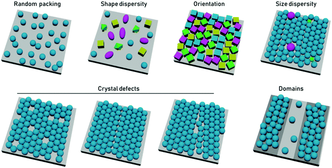
In terms of particle assembly, the quintessential ordered system is that of a colloidal crystal, i.e., a regular structure of particles that extend over length scales much larger than themselves. Order is not necessarily synonymous with a periodic structure, regular crystal structures, with high degrees of positional order exist such as those of protein crystals, which possess random orientational disorder between individual proteins. Disorder is typically defined as deviation from an idealized ordered system. Within disordered structures, the position of the elements cannot be determined exactly and are instead described by statistical properties. Correlated disorder refers to systems in which variations in interparticle distance occur within a range. In the case of diffraction patterns from systems with correlated disorder, diffuse rings from continuous scattering rather than discrete points (from Bragg reflection) are observed.43Disorder can be present in multiple ways. In the case of close-packed systems these include local defects (point/line defects and vacancies), particle polydispersity, poor particle packing, orientational disorder when using anisotropic particles, and inhomogeneous particle shapes or deposition patterns (Fig. 2). In the case of non-close packed systems, this also includes irregular spatial distributions of particles. In 2D particle assemblies, the level of disorder can be quantified by correlation functions, a pair correlation function for the position of the element, an angular correlation function for the orientation of the particles. However, some other types of disorder would not be apparent in these correlation functions, such as point lattice defects and polydispersity in non-close packed assemblies. These types of disorder can be seen by other quantification strategies, such as the bond orientational order parameter.
Truly disordered systems will have no crystalline domains. In this case, the pair distribution function is equal to one and no correlation is found at any length scale.44 Zero correlation is not truly achievable in particle assemblies because particles cannot penetrate each other and thus must exhibit some degree of correlation.
Controlled disorder refers to the engineering of systems to be randomly organized but restricted within a predetermined set of parameters. In the case of colloidal films, such systems will have a fixed level of correlation between individual particles in terms of their spatial and orientational organization. As of today, relatively few research groups have intentionally introduced disorder into two-dimensional assemblies of particles,12 and even less so in the case of films assembled through evaporative techniques. However, many of the systems currently found in the literature do offer routes to deliberatively introduce disorder. Hence, we discuss the conditions that have been observed experimentally to provide an increase in disorder in convectively assembled films.
2.2. Quantifying disorder in 2D colloidal films
Several techniques exist to quantify disorder in colloidal films including Fourier analysis of microscopy images, X-ray or neutron scattering, radial distribution functions, and Voronoi diagrams and Delaunay triangulations. We will briefly address each of these, and encourage the reader to consult Lotito and Zambelli's recent comprehensive reviews on this topic for further insights.45,46 Disorder can be measured on different scales both the long-range via macroscopic techniques, such as Fourier analysis and scattering techniques; and short-range through analysis of local bond order. We discuss these techniques in the following paragraphs.A fast and convenient approach to quantifying order in colloidal films is Fourier analysis of images. Fast Fourier transform algorithms allow images of particle monolayers to be analyzed in terms of their component spatial frequencies with minimal processing time. Highly ordered monocrystalline films produce ordered patterns of high intensity spots, whereas these spots smear into circular rings for polycrystalline samples. As disorder is increased in the sample, these features drop in intensity and eventually devolve into a 2D Gaussian. The radially averaged Fourier transform intensity can reveal the length scales of ordered regions, examples of this sort of analysis are ubiquitous in literature.14,47,48 The quality of the results from this technique is highly dependent on parameters such as image contrast, resolution and focusing because they are calculated from pixel intensities, rather than particle positions.
Crystalline order can be directly probed through scattering techniques which analyze a large area of the monolayer, providing information about disorder at the macroscopic level. While light diffraction14,49–54 and neutron scattering55,56 have been used to characterize colloidal films, small-angle X-ray scattering (SAXS) is a far more common method to characterize disorder in such films.57–66 Light diffraction is limited to films containing particles with diameters above the optical diffraction limit, whereas SAXS and neutron scattering can resolve much smaller structures. As with Fourier analysis, the formation of peaks and rings is indicative of crystalline structure. Disordered samples present Gaussian scattering patterns.53,61 The intensity and width of the peaks in the scattering patterns of monolayer films provide information about the level of order within a film and can be analyzed to provide a global value for the layer in the form of a structure factor. The sine Fourier transform of these patterns is the pair correlation (or radial distribution) function,  , which expresses the probability of finding a particle at a given radial distance from another particle.67
Low level image analysis techniques analyze the structure of the film in terms of particle positions. These are identified from images of particle films obtained via atomic force microscopy (AFM), electron microscopy, or optical microscopy. The particle positions can be analyzed statistically, providing a quantitative evaluation of the spatial variation of monolayer structure. The pair correlation function can be calculated directly from this dataset.68–70 However, more complex analyses can provide further insight into local order variation throughout the sample. The simplest of these is Voronoi–Delaunay analysis, where the Voronoi cell of each particle is determined. The edges of each cell are defined as being equidistant between two nearest neighbors and the vertices equidistant between three nearest neighbors (Fig. 3). Each edge is thus intersected by a single nearest neighbor bond. For a perfect hexagonally close packed crystal, the number of nearest neighbors, Nj, is six. More disordered lattices will feature Voronoi cells of varying area71,72 and differing number of sides.47,73,74 Statistical analysis of the population of these cells enables the calculation of values describing the entire population, such as the variance or global Voronoi entropy, Svor.47,75
 | ||
| Fig. 3 Example Voronoi diagrams for (a) a highly ordered non-close packed monolayer and (b) a disordered non-close packed monolayer. | ||
Another common approach is the quantification of local bond order, though the analysis of changes in the angles between nearest neighbors, which can be expressed through the bond-orientational order parameter, ψn:76–79
 | (1) |
 is the angle between a reference direction and the vector between particle centers j and k. Given a sufficient definition of ‘nearest neighbor’, ψ6 can be used as a measure of the local bond order throughout a 2D crystalline lattice.80 For well-ordered 2D hexagonally close-packed lattices, ψ6 will vary between 0.9 and 1.81 It is widely used as a measure of the order in 2D particle assemblies (i.e. ref. 72, 74, 78 and 81–89). Additionally, the complex phase of this function,
  , can be used as a direct measure of local crystalline ordering. θ6 varies between 0° and 60° for a hexagonally close-packed crystal. Any variation in the phase or amplitude of this parameter is indicative of disorder in the lattice due to polycrystallinity or the inclusion of lattice defects.
There are limitations to this approach however. The results produced by this analysis are highly sensitive to the definition of nearest neighbor used. This is normally defined as any particle center inside a radius of some multiple of the particle diameter, D, for close-packed monolayers this is typically between ∼1.2D and ∼1.4D as determined by the position of the first trough in the radial distribution function,  .90 However, for non-close packed monolayers, such as that depicted in Fig. 3b, these definitions become problematic due to highly variable bond distances resulting from low packing fractions and the presence of voids. It is also not continuous as a function of particle coordinates, making it less practical as a mathematical parameter.91
To solve these problems, ψn can be weighted to reflect local geometric features in the lattice by combining this protocol with Voronoi analysis. In this case, a relative length factor,  , is included in the definition of ψ6, where
  is the length of the intersected Voronoi edge and L is the perimeter of the Voronoi cell (
 ):90,92–94
 | (2) |
This parameter robustly describes the order within a 2D colloidal crystal. For a perfect hexagonally close packed crystal, this parameter returns to the form given in eqn (1). This formalism is functionally identical to the Minkowski structure metric used elsewhere.47,91,93 Images of assembled particles can be analyzed to find regions that demonstrate predominantly 4-, 5-, or 6-fold symmetry, distinguishing between regions of hexagonally close packed crystallinity and defects.95 The local crystalline phase, θn, can also be analyzed to identify grains.81
There are also techniques to characterize the component crystallinities within a monolayer to give a more holistic description. One such example is persistent homology96–100 which describes the particles in terms of topological parameters such as the Betti numbers. Other statistical techniques, such as principal component analysis, can also identify small changes in global order between different films.100
3. Fundamental concepts of evaporative particle self-assembly
While several approaches exist for the self-assembly of colloidal films, we focus here purely on the use of evaporative self-assembly. Evaporative assembly techniques offer a simple, scalable, and cost-effective route to prepare colloidal films, which make them attractive for future industrial processes. Here, we discuss the underlying principles behind these techniques, and the available protocols which use them in the preparation of colloidal films.In evaporatively driven particle assembly, a volume of colloidal solution is directed over a substrate establishing a triple-phase contact line between air, the solvent, and the substrate. Good wettability ensures the formation of a continuous film. Without this, dewetting can occur and islands can form. This can be particularly problematic if the contact angle is too high (>20°), because no particles will be deposited (Fig. 4). But under ideal conditions, tightly packed and homogeneous layers of particles will result. Depending on the technique employed, the solvent recedes due to either substrate withdrawal from the solution or from solvent evaporation. Subject to the rate of solvent recession, there are two regimes known as which are referred to as the ‘convective’ regime and the ‘Landau–Levich’ regime.
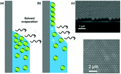 | ||
| Fig. 4 (a) A high contact angle, where particles are not pinned to the surface and no film deposition is achieved. (b) A good wetting with a contact angle of less than 20°, where convective flux brings particles to the drying line. (c) A continuous monolayer of polystyrene latexes. (c) Reproduced with permission from ref. 101. Copyright 2007 American Chemical Society. | ||
Regime I: convective assembly: Also known as the ‘capillary’ regime, convective assembly is characterized by particles being brought to the drying line by an evaporatively-driven flow. It occurs at low speeds (≲0.1 mm s−1 in ethanol at 30 °C), where evaporation in the meniscus is the dominant process driving particle transport. Particles concentrate close to the drying line and become trapped at the meniscus edge, forming dense particle arrangements on the substrate. The particles within the forming film are then bound by interparticle and particle–substrate forces. Further evaporation then produces a dry film. Convective particle flow is dependent on solvent evaporation rate, the buoyancy of the particles, the force of Brownian motion on the particles, and the substrate withdrawal rate. Evaporative flux can be controlled through ambient temperature, pressure, and humidity, alongside solvent volatility.
However, working against convective particle transport is an osmotic pressure, expressed by Fick's law: a higher particle concentration in the drying line leads to diffusive flow towards the bulk solution.103 Particle size, shape, and density, as well as interparticle interactions, contact angle, and solvent volatility, all influence whether convection or diffusion is dominant. Collective particle transport towards the triple line is faster for neutrally charged particles than for positively or negatively charged particles.103 This is due to increased diffusion rate in concentrated dispersions of charged particles. For charged particles, interparticle interactions are more important than substrate–particle interactions in determining film thickness.103
The number of particle layers, k, in the obtained films is inversely proportional to the substrate velocity speed.104–106 In this regime, continuous film formation can only be achieved if the substrate velocity, vs, is equal to the crystallization velocity, vc, as expressed by the Dimitrov–Nagayama equation:104
 | (3) |
As substrate velocity is decreased, the well-known phenomenon of ‘stick-slip’ becomes increasingly pronounced (Fig. 5). This is caused by contact-line pinning, where the meniscus becomes stuck and then elongated by the motion of the substrate. Eventually the surface energy of the meniscus becomes too great, leading to the contact line suddenly ‘slipping’ to the next pinning line.107,108 This process is periodic and causes particle deposition to occur in regular bands parallel to the meniscus.
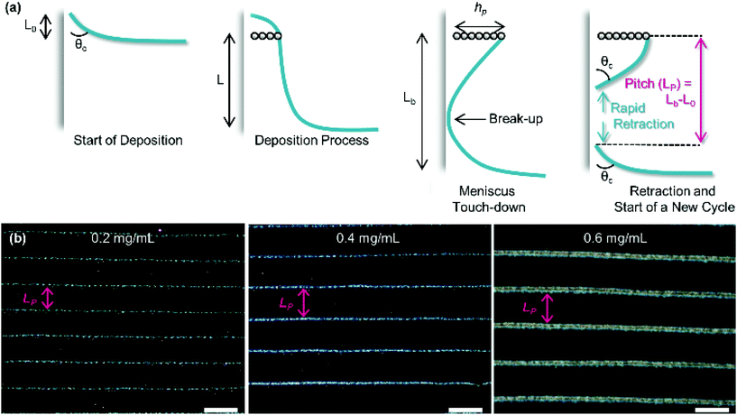 | ||
| Fig. 5 (a) The process of stick-slip, where particles pin the meniscus, the meniscus becomes stretched, the meniscus touches down, breaking contact with the bulk solution and a new deposition begins. (b) Optical microscopy images showing the dependence of pitch on particle concentration in the solution (concentrations of 0.2, 0.4 and 0.6 mg mL−1 from left to right). The scale bars represent 100 μm. Reproduced with permission from ref. 102. Copyright 2020 American Chemical Society. | ||
Regime II: ‘Landau–Levich’ assembly: Also known as the ‘advective’, ‘draining’, or ‘viscous drag’ regime, Landau–Levich assembly occurs at high speeds (≳1 mm s−1 in ethanol at 25 °C). Here viscous forces within the liquid dominate. In this regime, a static meniscus at the evaporative drying front no longer exists and instead the solvent viscosity produces a thin continuous film of the coating solution having approximately constant thickness across the substrate. This film then dries through draining leading to the deposition of particles on the substrate. The shearing induced by draining can lead to vertically striped deposition patterns under some conditions.102 In the formation of Landau–Levich films, the viscous, gravitational, and surface tension forces in the trapped fluid layer exist in equilibrium. The Landau–Levich equation can be used to describe the thickness of this fluid layer, h0:
 | (4) |
Transitional regime: Between the convective and Landau–Levich regimes, there exists a transitional regime where both assembly mechanisms occur in tandem. It is here that the thinnest possible films are achieved (withdrawal rate between 0.1 and 1 mm s−1 in ethanol at 25 °C).112 In this regime, a liquid film is formed, but evaporation occurs faster than the liquid film can drain. A drying front is established at the top of the liquid film causing convective assembly to occur within the liquid film itself.113
In all regimes, the ability to form good quality films requires the prevention of dewetting by using substrates with good wettability. Both assembly processes are sensitive to changes in surface tension, which can be controlled through solvent selection and the inclusion of surfactants in the coating suspension.48,104,114
Colloidal stability, through either electrostatic or steric approaches, is crucial to avoiding sedimentation during the coating process.115 Sedimentation is particularly prevalent for larger particles, where surface functionalization can no longer overcome sedimentation forces on the particle. Remedial actions to address this problem for larger particles include: increasing the rate of evaporative flux (increasing deposition speed), using solvents with higher viscosity (reduced sedimentation velocity) or density (increased particle buoyancy).113
There are several ways to deposit films using these principles, the most common being: drop-casting, dip-coating, and drag-coating. We point interested readers to a recent in-depth review which discusses this topic for further insights on the assembly of these films.45
3.1. Drop-casting
The simplest method of evaporative assembly is that of droplet evaporation or drop-casting,116–121 which is the free evaporation of a droplet of colloidal solution placed directly on a substrate. The area of the substrate that can be coated is thus restricted to the size of the droplet. As the suspension evaporates, particles are drawn towards the contact line resulting in the ‘coffee-ring’ pattern, in which thick particle deposits occur at the edges of the droplet.122 Several adjustments have been proposed to avoid coffee-rings, including introducing a cell wall, controlling pH, and drying in a solvent-saturated atmosphere.123–126 It is difficult to control such processes, and inhomogeneous deposition is still an issue, with coatings often simultaneously containing regions of multilayer, monolayer and submonolayer.3.2. Dip-coating
This technique has been used to coat substrates with polymers,105,127–129 biomolecules,130–134 and, most relevantly, colloidal solutions.104,135,136 Typically, dip-coating is performed by submerging a substrate in a reservoir containing a coating suspension and then withdrawing it vertically at a known velocity. Many factors impact the physical qualities of the film: the withdrawal rate, the number of dip cycles, the contact angle (substrate nature and solvent polarity), the evaporation rate (e.g., chamber temperature and pressure, solvent volatility, and relative humidity) and the solution properties (e.g., viscosity, surface tension, and the particle concentration), as well as the particle properties (surface chemistry, size, shape, and material).Many reports in the literature control ambient humidity,137,138 pressure,115 or introduce airflow over the meniscus139,140 to regulate the evaporation rate of the coating solution. Control of the formed film can also be exerted through modification of interparticle interactions through changing colloidal surface charge via the solvent pH,141 or screening these interactions through the inclusion of electrolytes114 or charged polymers135 in the coating solution.
Compared to other techniques such as spin coating, relatively little coating solution is wasted, as the material left in the reservoir can be reclaimed. However, there are losses to the walls of the reservoir and the other substrate surfaces. The area that can be coated is in theory only limited by the sizes of the substrate and the reservoir. Also, the large volume of supension required to fill the reservoir (relative to the amount used in coating the substrate) means that this technique is not ideal for small-batch processes or suspensions that can only be prepared in a small volume. It is a relatively simple experimental set-up, although requires good control of many parameters to yield reproducible films.
3.3. Drag-coating
A closely related technique to dip-coating is drag-coating, or ‘doctor-blade’ coating, which is the horizontal counterpart to dip-coating. It similarly has found a use for coating substrates with biomolecules,142–145 polymers,146–148 and particles.149–151 In this set-up, a small volume of the coating solution placed between the substrate and a blade is guided across the substrate. Capilary forces hold the colloidal solution in contact with both the substrate and blade, and assembly occurs at the trailing edge of the volume.In the angled-blade configuration, the blade can be moved in either direction with respect to the substrate. When moved in the forward direction, assembly occurs below the blade,87 and when moved in the reverse direction assembly occurs at the contact line which trails the blade.152,153 Higher crystallization velocities are observed in the reverse direction.152 Drag-coating involves the same parameters as dip-coating, but also includes additional considerations about properties of the blade, such as the angle,87,151,154 surface functionalization,87 and height above the substrate.155 The blade applies pressure to the meniscus and through variation of the blade height, the curvature of the meniscus can be reduced, in turn minimizing contact line pinning and variation in the film thickness.155
Drag-coating apparatuses are typically more compact than dip-coaters but are limited by the small volume of coating solution used, which restricts the area that can be coated. There have been some attempts to modify this technique to enable the solution to be continuously fed below the blade using a syringe pump at a rate matched to the evaporative flux, thus enabling continuous coating over large areas.156 The relative fluxes of both the solvent and particles must be matched to maintain a constant concentration in the reservoir and make the process truly continuous.
Several changes to this technique have been implemented, such as modifying interparticle interactions through pH control,143 or electrostatic screening using electrolytes,157 as well as changing the evaporation rate.145,153 Some approaches assist monolayer formation through the vibration of the sample in the plane of meniscus travel (lateral vibration). Vibrational frequencies in the range 20 to 50 Hz show a significant increase in the range of blade velocities that produce continuous monolayers.158–160 Vibrations out of the plane of the substrate (vertical vibration) show similar results at higher frequencies (3 kHz).161
In summary, two regimes of particle assembly are accessible by these techniques. In the Landau–Levich regime there is little that can be done to influence the degree of disorder; only the particle density can be regulated. By contrast, the convective assembly regime has a wide range of parameters with which disorder can controlled. These will be explained more fully in the next few sections.
4. Using particle properties to control disorder
One strategy to control particle deposition is modification of the particles' physical characteristics. In this section we will review the effects of changing particle polydispersity and the use of anisotropically shaped particles on their assembly.4.1. Disorder arising from particle size polydispersity
Typically, polydispersities below 10% have little impact on the crystalline structure.162 Polydispersity being defined as where Di is the particle diameter and angular brackets indicate the ensemble average.162 Polydispersities between 10 and 15% can lead to partially ordered systems, with values >15% producing disordered systems. It is energetically preferable for hard spheres to be packed in crystalline domains compared with disordered arrays, as the thermodynamic stability increases upon crystallization. It has been observed that due to chemical interactions between spheres, polydisperse samples will segregate into multiple crystals with different unit cell sizes.163 Alternatively, an AxBy unit cell, where A and B are spheres of different diameter, is also an energetically favorable arrangement. Thus, disorder should be induced via kinetic quenching or by using chemical forces or physical topography.
Lau and Russel have described the effect of surface charge on the organization of size polydisperse particles by drag-coating (Fig. 6).164 Lateral capillary thickness, h, of the liquid film is greater than or equal to the particle diameter, D. Once the liquid film thickness drops below the particle diameter, capillary forces pull the particles together. The smallest particles are still free to move, while the larger particles are immobilized. However, when the suspension is deionized, lateral movement is not determined solely by capillary pressure. It seems that the uniformity of the meniscus curvature is lost when the solution is deionized, leading to inhomogeneous capillary forces and a loss of order. Moreover, the repulsive double layer around the particle, rather than the core diameter, determines the effective particle size and thus their movement. Smaller particles have effectively the same lateral mobility as the larger particles and are incorporated into the assembly, rather than segregating to the edge of the ordered domains formed from larger particles. In summary, to control disorder, capillary forces increase order when the electrostatic interactions are higher.
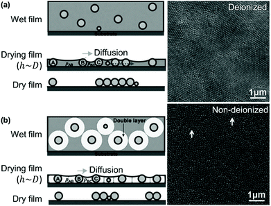 | ||
| Fig. 6 Particle monolayers prepared using silica particles in (a) non-deionized and (b) deionized water show differing degrees of order as a function of polydispersity. Figure adapted with permission from ref. 164. Copyright 2014 John Wiley & Sons. | ||
Ions in the solvent create more homogeneous capillary forces, particularly when using hydrophobic particles, such as polystyrene. Thus, by tuning the electrostatic properties, the degree of disorder can be tuned in a polydisperse system.
The impact of polydispersity is shown by assembling monolayers of both monodisperse and polydisperse particle suspensions.165 The polydisperse sample led to amorphous films with a volume filling fraction between 42 and 54%, compared with between 57 and 61% for monodisperse suspensions. In the crystalline monolayers, brilliant angle-dependent colors could be observed, due to scattering from close-packed domains of varying orientation within the film. This effect was absent in the disordered monolayer, where if color is observed, it is from interferences within the film rather than crystalline domains.
4.2. Controlling disorder with particle shape
Introducing anisotropy into convectively assembled systems has important implications because it changes both interparticle capillary interactions and restricts the possible packing configurations. It also introduces a new form of disorder in the form of angular correlation, which is unquantifiable when using isotropic particles. We focus here on films using rod-like and cubic particles.We used convective assembly to control the disorder in bands of tightly packed silica helices having a wire-like structure.102 Ordered assembly was possible in both the Landau–Levich and convective assembly regimes (Fig. 7). At low speeds, in the convective regime, the helices oriented themselves parallel to the meniscus and a high degree of order was obtained, classified by order parameter S. Defined as S = 〈2![[thin space (1/6-em)]](https://www.rsc.org/images/entities/char_2009.gif) cos2
cos2![[thin space (1/6-em)]](https://www.rsc.org/images/entities/char_2009.gif) θ − 1〉 where θ is the angle between helices and angular brackets indicate the ensemble average. When S = 1, the nano-objects have no orientational disorder, and when S = 0 the nano-objects have a random angular distribution. In the convective assembly regime, the quantity of polymer additive, that is polyacrylic acid, determined the degree of order. In absence of polymer, the assembly was completely random. Silica
θ − 1〉 where θ is the angle between helices and angular brackets indicate the ensemble average. When S = 1, the nano-objects have no orientational disorder, and when S = 0 the nano-objects have a random angular distribution. In the convective assembly regime, the quantity of polymer additive, that is polyacrylic acid, determined the degree of order. In absence of polymer, the assembly was completely random. Silica![[thin space (1/6-em)]](https://www.rsc.org/images/entities/char_2009.gif) :
:![[thin space (1/6-em)]](https://www.rsc.org/images/entities/char_2009.gif) polymer mass ratios of 1
polymer mass ratios of 1![[thin space (1/6-em)]](https://www.rsc.org/images/entities/char_2009.gif) :
:![[thin space (1/6-em)]](https://www.rsc.org/images/entities/char_2009.gif) 5 to 1
5 to 1![[thin space (1/6-em)]](https://www.rsc.org/images/entities/char_2009.gif) :
:![[thin space (1/6-em)]](https://www.rsc.org/images/entities/char_2009.gif) 20 were assembled, producing order parameters between 0.74 and 0.86. The order parameter was increased further, attaining S = 0.95, by controlling the concentration of helices in solution. Thus, by tuning the quantity of nano-objects and the amount of lubricant in the drying line, the degree of disorder can be tailored.
20 were assembled, producing order parameters between 0.74 and 0.86. The order parameter was increased further, attaining S = 0.95, by controlling the concentration of helices in solution. Thus, by tuning the quantity of nano-objects and the amount of lubricant in the drying line, the degree of disorder can be tailored.
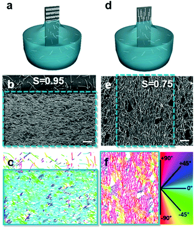 | ||
| Fig. 7 Assembly in the (a) convective and (d) Landau–Levich regimes, where the (b and e) degree of disorder between assembled helices varies. (c and f) The order parameter, S, was obtained by treating the images to determine the orientation of the helices relative to the withdrawal direction. Scale bars represent 1 μm. Reproduced with permission from ref. 102. Copyright 2020 American Chemical Society. | ||
The aspect ratio in assembled nanorods has a significant impact on the degree of order.168–170 In the case of rigid nano-objects, small aspect ratios provide more disordered films, with higher alignment for larger aspect ratios.170 With more flexible nanowires, a longer aspect ratio led to a higher degree of disorder,171 unless a significant shear force was applied.172 For these objects, a balance is struck between Brownian and shear forces.172
As in the case of spherical particles, the use of particles with a strong surface charge result in a higher degree of organization.170 Moreover, a faster rate of convective flow increases the degree of order.169 However, electrostatic charge also plays a role in particle–particle interactions. In one study, in the absence of counter-ions, lateral repulsion between rod-like particles led them to predominantly assemble in a head-to-tail arrangement.173 A faster rate of convective flow has been found to increase the degree of order.169 Conversely, an evaporation rate that is too high has been found to position nanorods before they have the time to organize, creating more disordered materials.168
By using the lessons learned from spheres, the degree of order can be rather easily tuned in the assembly of anisotropic rods and wires. These objects tend to align either head-to-tail or side-to-side, depending on various interparticle forces. Aligned, non-close packed assemblies are not observed in absence of an external field or a template. More typically, during the evaporative assembly of these objects, highly aligned and tightly packed systems are observed, where higher aspect ratios increase the degree of order.
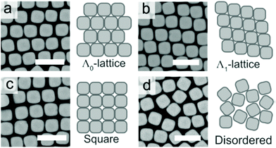 | ||
| Fig. 8 The (a) Λ0-lattice, (b) Λ1-lattice (c) square lattice, and (d) disordered assembly patterns observed in SEM micrographs. Scale bars represent 2 μm. Reproduced with permission from ref. 95. Copyright 2019 American Chemical Society. | ||
Meijer et al. examined the effect of corner sharpness on the preferred orientation and lattice of cube assemblies (Fig. 9).95 Corner sharpness was controlled by changing the thickness of a silica shell around a cubic hematite particle; thicker coatings produced more rounded nano-objects. Cubes were described as superballs satisfying the following relationship:
 | (5) |
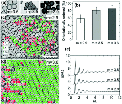 | ||
| Fig. 9 (a) TEM images of cubes with different corner sharpness. The scale bars represent 1 μm. (b) The % of cubes with orientational order for cubes with differing corner sharpness. SEM images of cubes (c) m = 2.9 and (d) m = 3.6 (defined in eqn (5)) with colors indicating the orientation and organization of cubes relative to neighboring cubes. The scale bars represent 5 μm. (e) An average radial distribution for cubes of differing corner sharpness. Reproduced with permission from ref. 95. Copyright 2019 American Chemical Society. | ||
5. Using dispersant properties to control disorder
An alternative route to changing the assembly behavior is to use the properties of the suspending medium. In this section we discuss the effects of including ions to screen particle interactions and controlling ambient pressure to change the rate of solvent evaporation.5.1. Disorder arising from electrostatic charges
In convective self-assembly there are two classes of electrostatic interactions to consider: particle–substrate and particle–particle. Tightly packed particle assemblies result when the particles and the substrate have a repulsive interaction. In this case, the particles do not cluster near the substrate and assemble during the last stages of drying. The extra time allows the particles to accumulate and arrange into an ordered, tightly packed configuration, which minimizes surface energy. Electrostatic interactions can be controlled through the inclusion of ions in the coating solution, through both electrostatic screening of charged particles and changing the solution pH (Fig. 10).157 At higher ion concentrations, electrostatic screening reduces particle–substrate repulsion allowing the particles to be deposited before they reach the drying front.157 Rödner et al. have observed that not only particle–substrate adhesion, but also particle–particle adhesion occur at high ionic strength.70 Alternatively, by deliberately tuning solvent pH to increase particle surface charge, electrostatic repulsions are increased and prevent deposition and interparticle aggregation. Joshi et al. demonstrated this by adding [OH−] to a suspension of silica spheres to increase monolayer packing and order.157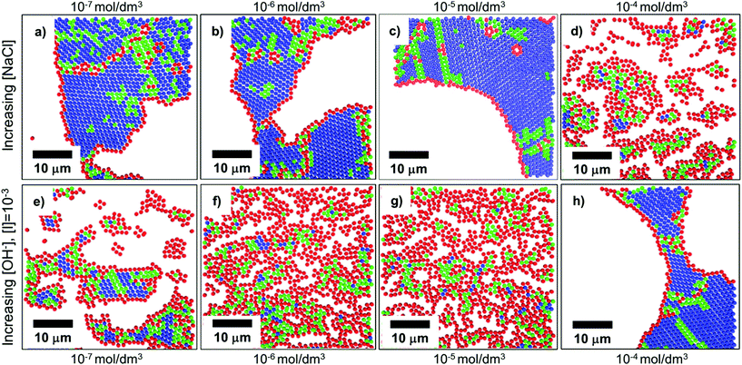 | ||
| Fig. 10 Confocal scans of submonolayers, colored to indicate the number of nearest neighbors and bond order: blue indicates 6 neighbors with high bond order, green indicates 6 neighbors with medium bond order, red indicates <6 neighbors. (a–d) As ionic strength increases through the addition of NaCl to a colloidal solution, repulsive forces are shielded, and particles become more disordered due to premature deposition on the substrate. (e–h) As electrostatic charges are increased through the addition of [OH−], order is improved. Reproduced with permission from ref. 157. Copyright 2015 American Chemical Society. | ||
Layer thickness is also impacted by electrostatic forces. In terms of layering, particle–substrate attractive forces are overcome by particle–particle repulsive forces, leading to thinner deposits.175 When repulsive electrostatic forces between particles are weak, it is easier to pack particles together, leading to the deposition of multiple layers and longer meniscus pinning in the convective assembly regime.175
To summarize, disorder is increased by having attractive forces or charge screening, leading to particle deposition and immobility prior to the film drying.
5.2. Disorder arising from reduced pressure
A higher flow rate towards the drying line leads to better organization as the higher particle concentration leads to tighter packings. The evaporation rate is approximately inversely proportional to the pressure.176 Thus initially decreasing the pressure leads to an increase in the order within a colloidal film. However, if evaporation rate is too fast, some particles are deposited and immobilized before finding the lowest energy organization.176 Thus, disorder in the assembled films is highest at reduced pressure where evaporation rate is extremely fast.6. Using patterned substrates to control disorder
Another option beyond modifications of the particles or the solvent is to pre-treat the substrate to control the distribution of particles. This can be achieved through purely bottom-up approaches, by which chemical patterns are generated on a substrate through self-assembly. It can also be achieved via a combination of top-down and bottom-up techniques in which a substrate is typically prepared via lithography to produce either chemical or topographical patterns. These approaches offer more precise particle positioning, and thus a higher degree of control over correlation between particles but have the limitations of lithographic approaches. Substrates produced via these means cannot be scaled up in the manner of the previous approaches due to the large amount of time required to prepare them. Hence, a trade-off currently must be made between the high degree of control offered by these approaches and their limited scalability.6.1. Chemically patterned substrates
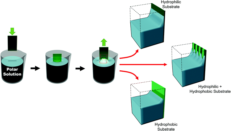
Such substrates can be broadly grouped into two different approaches used to chemically influence particle positioning: inhomogeneous chemical interactions (electrostatics, van der Waals, hydrogen bonding or even covalent bonding) and nonuniform wettability.177,178 Chemical contrast, where different chemical functionalities are pre-patterned on a substrate, creates differences in particle–substrate interactions and solvent–substrate interactions and in the evaporation rate of certain zones of the substrate.179 There are many reports of soaking chemically patterned substrates in a colloidal suspension and allowing the particles to adhere to targeted domains through particle–substrate interactions. Patterns achieved through such particle–substrate interactions lie outside the scope of this review. We encourage the interested reader to refer to other articles on the topic.178,180,181Selective wetting targets particle deposition on to particular domains. In the regions of particle deposition, thanks to capillary forces, highly ordered hexagonally close-packed domains self-assemble.182 In terms of substrate–solvent interactions, the change in the surface energy translates into a change in the meniscus shape. If the substrate has chemical functionalities which induce a wettability contrast, the meniscus will deform between zones (Fig. 11). For polar solvents, the meniscus will be convex in hydrophilic regions and concave in hydrophobic areas. However, the meniscus can only be deformed over certain length scales. Due to the intermolecular forces between solvent molecules, the transition from a concave to a convex meniscus shape requires several micrometers.187 Certainly, the contact angles between the hydrophilic and hydrophobic zones has an impact on the resolution. However, Fustin et al. observed that the lower limits for sharp patterning were 4 μm for the hydrophobic zone (non-stick zone) and 10 μm for the hydrophilic zone.188 The hydrophilic–hydrophobic contrast can be accentuated by adding surfactants.184 A stable meniscus shape occurs only when the hydrophilic portion is at least twice the width of the transitional area between the two domains. Belgardt et al. found that they could overcome limits of meniscus deformability, depositing particles in a thinner hydrophilic band by dip-coating at a 45° inclination.187 By changing the retraction angle, the angle of the meniscus is less steep. Thus, the differences between the contact angle of the hydrophobic and hydrophilic zones are decreased. By smoothing out this transition, the transitional area is decreased, allowing particles to be deposited in a very thin hydrophilic zone.
The block copolymer templated approach is particularly interesting for nanoparticles smaller than the block copolymer domains. Nanoparticles are suspended in a block copolymer solution and then formed into a thin film through solvent evaporation combined with either spin-coating, film casting, drop-casting, or rarely, dip-coating. In the framework of this review, we will discuss patterns formed through one-pot assembly. A more in-depth discussion of such materials can be found in other reviews.189,190 Block copolymer and nanoparticle co-assembly leads to the nanoparticles being positioned in a hydrophobic block, a hydrophilic block, or at the interface between the two. The nanoparticles can be designed to have a preferential affinity for one of the blocks (Fig. 13). Surface chemistry is not the sole factor influencing particle placement. There is an entropic influence related to the relative size of the nanoparticle and the block copolymer domains (Fig. 13).191,192 Smaller particles migrate to the interface, whereas larger particles position themselves fully within the corresponding block. By regulating the size and surface chemistry of these patterns it is possible to achieve targeted spatial control.
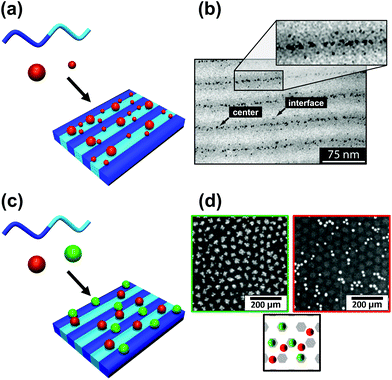 | ||
| Fig. 13 Selective deposition of particles of different (a and b) size and (c and d) nature on a self-assembled block copolymer film. (b) TEM image of a binary mixture of two particle sizes (D < 3 nm and D > 5 nm) deposited on a PS–PEP–PS triblock copolymer; smaller particles migrate to domain interfaces and larger particles tend to stay inside domains. (d) SEM images of silver nanoparticles on [PS(57k)-b-P4VP(18k)] (red/right) and gold nanoparticles on [PS(57k)-b-P4VP(18k)] (green left); affinity of gold for P4VP and of silver for PS. (b) Reproduced with permission from ref. 192. Copyright 2006 American Chemical Society. (d) Reproduced with permission from ref. 193. Copyright 2013 John Wiley & Sons. | ||
Evaporatively driven convection also impacts particle placement. Li et al. compared block copolymer–gold nanoparticle thin films prepared by both spin- and dip-coating (Fig. 14).194 The greater time elapsed during dip-coating allowed the micelles and nanoparticles to configure themselves on the substrate, resulting in particle migration to the interface. Control over the evaporation rate through the factors discussed above, particularly liquid film thickness and atmospheric conditions will regulate convective flux and thus kinetically control the rate of particle placement.
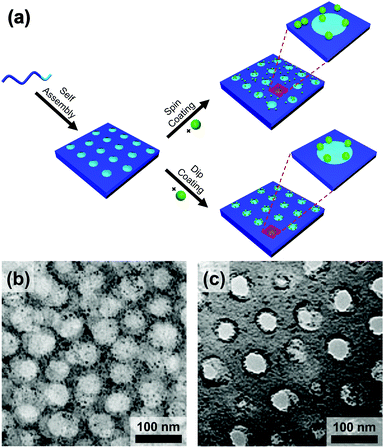 | ||
| Fig. 14 (a) Schematic of the block copolymer templating approach via spin-coating and dip-coating. TEM micrographs of thin films of block-copolymer (PS-b-P2VP)/gold nanoparticles prepared by (b) spin-coating and (c) dip-coating. Deposition by spin-coating leads to a random deposition of particles when deposition by dip-coating leads to a confinement of the particles at the interface between two domains. (b) & (c) Reproduced with permission by ref. 194. Copyright 2008 John Wiley & Sons. | ||
In this section, we discussed particle assembly on chemically patterned substrates and the self-assembly of nanoparticles using block copolymers. Chemical contrast influenced the shape and separation of the domains, and the quantity of particles within them. Disordered chemical contrast can be designed using top-down patterning techniques, or it can form through bottom-up self-assembly of patterns. Chemical patterning disrupts the continuity of particle deposition, allowing stopbands to be tailored.182
With additional complexity in the forces acting on the colloidal solution, the particles demonstrate unusual, and less ordered, deposition behavior. For instance, wettability contrast destabilizes the shape of the meniscus and changes the evaporation rate along the drying line. This is apparent when using motif bands parallel to the meniscus, which cause the contact angle to vary as the substrate is withdrawn acting in opposition to stick-slip behavior. Also, the high degree of curvature in some motifs prevents the close packing of spheres leading to the formation of lattice defects. In summary, disorder is generated, but moderated over large length scales via chemical patterning.
6.2. Topographically patterned substrates
An approach that offers greater control over particle distribution than chemical patterning and non-templated techniques is that of particle deposition onto topographically patterned substrates. Such substrates are typically produced through the modification of a polymer layer applied above a flat substrate through top-down techniques such as lithography. Lithography-free protocols also exist, including wrinkles induced through repeated plastic deformation197 and the grooves of optical discs.198 Normally these substrates feature depressions or trenches with at least one dimension of similar magnitude to the particle. Particles can then be directed over the substrate in high concentration and the particles are trapped within the depressions through capillary action.While convection is the process transporting particles to the meniscus, and thus to the traps, assembly within the traps themselves is driven primarily by capillary forces (Fig. 15a). Particles remain mobile after the triple contact line has receded beyond the physical trap allowing further reorganization. Mobility within the traps is dictated by the strength of the capillary forces between particles and between the trap and the particles. Hence particle organization within physical traps is independent of whether convective flow is used. Thus, while discussion in this section is primarily focused on topographically patterned substrates used in combination with convective assembly, some studies have been included that feature applicable results, which do not use convective assembly. We present examples organized into four classes of physical pattern.
 | ||
| Fig. 15 (a) Schematic of the convective self-assembly process on topologically patterned substrates. Trapping of single nanoparticles into arbitrary assemblies with a high degree of accuracy in the positional and orientational positioning. (b) High magnification SEM micrograph of the left eye of the inset convectively assembled image of a sun comprised of 60 nm gold nanospheres positioned with pixel level precision (c) gold nanorods assembled into complex motifs with arbitrary orientations. Scale bars represent 250 nm. (a) & (c) Reproduced with permission from ref. 195. Copyright 2017 Nature Publishing Group. (b) Reproduced with permission from ref. 196. Copyright 2007 Nature Publishing Group. | ||
Most literature reports of topographically-templated clusters consist of arrays of well-separated, uniform clusters.202,209–213,219 Greybush et al. found that increasing the width of such traps beyond seven particles led to increasing disorder in the clusters.212 They attributed this to polydispersity, which prevented regular close-packing. The increase in disorder was visible in the optical spectra of individual clusters with complex features and blue-shifted peaks relative to close-packed clusters of monodisperse gold nanospheres.
Shillingford et al. were able to create hexagonally close-packed, square, and disordered packings within arrays of square traps by changing particle volume fraction, and tuning the depth and resolution of the traps.222 Disordered packings were observed at low volume fractions, with square and hexagonally close-packed organization at higher fractions. Amorphous monolayers could be obtained using poorly resolved traps featuring kinks and breaks which disrupted lattice order. In the case of linear bands, confinement applied consistently along a single axis results in linear structures, ranging from single particle columns to several particle thick bands.198,214,215,219,223,224 The disorder within these bands is highly sensitive to the width of the channel, Λ, versus the width of a close packed lattice. Disorder is obtained by deviating from a set of specific widths, which can be calculated from the relationship  , where D is the particle diameter, and n is the number of particle columns in the channel, as seen in Fig. 16. As polydispersity and particle mobility must be accounted for, traps must be slightly wider than these widths to produce close-packed lattices. A small additional deviation results in the appearance of line defects (Fig. 16a and b).219 Conversely strong deviations from these ideal values leads to disordered monolayers (Fig. 16c–e).219,223 The packing fraction in the assembled regions of monolayer serves as a good figure of merit to quantify disorder as a function of channel width (Fig. 16f).223
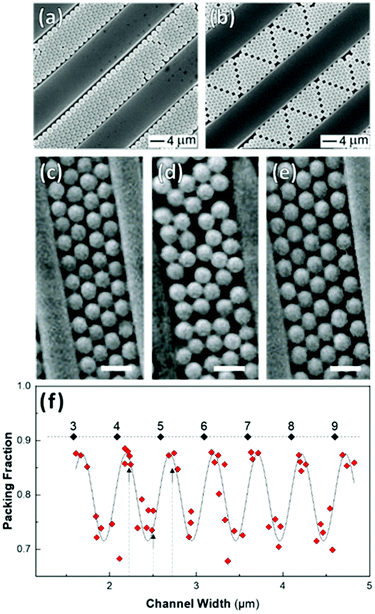 | ||
| Fig. 16 Effect of confinement on particle organization. (a & b) Deviation in channel width, from a value commensurate with a close-packed lattice, induces the formation of linear defects. (c)–(e) Disordered assembly within the channel is caused by intermediate channel widths between those compatible with a close-packed lattice(as seen in (d)). Scale bar represents 1 μm (f) Monolayer packing fraction as a function of channel width showing the decrease in packing density when widths incommensurate with close packing are used. Dashed line = 0.9069 (max packing fraction). Labels are the number of particle columns. (a) & (b) Reproduced with permission from ref. 219. Copyright 2003 John Wiley & Sons. (c) – (f) adapted with permission from ref. 223. Copyright 2002 John Wiley & Sons. | ||
In the case of striped patterns, values of Λ < √3D/2 result in an increasingly square lattice with ever larger voids down to a critical value of Λ = √2D, below which it is no longer possible to populate all traps on the substrate (Fig. 17a–c). Values of Λ > √3D/2 result in decreasing overlap between particles trapped in neighboring stripes, also leading to larger void formation. If Λ is increased beyond D, then the stripes are completely decoupled and there is no longer any correlation between neighboring particles in the axis parallel to the traps.220,228
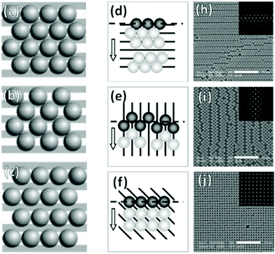 | ||
| Fig. 17 Particle monolayers templated using patterns smaller than the particle. (a)–(c) Varying inter-trap distance, Λ leads to changes in particle organization i.e. (a) perfect matching (Λ = √3D/2), (b) Λ < √3D/2, and (c) Λ > D. (d)–(j) Trap orientation relative the meniscus impacts packing structures. Arrows indicate meniscus travel direction. (d) Parallel traps cause hexagonal close-packing with parallel defects. (e) Perpendicular traps cause square packing with perpendicular defects. (f) 45° traps cause near-perfect square lattice. (h)–(j) SEM micrographs of (d)–(f) with inset 2D autocorrelation graphs. Scale bars represent 10 μm. (a)–(c) Reproduced with permission from ref. 220. Copyright 2004 John Wiley & Sons. (d)–(i) Reproduced with permission from ref. 221. Copyright 2008 John Wiley & Sons. | ||
Kadiri et al. have explored how disorder can be introduced into an otherwise close-packed monolayer using pillars.225 When pillars were closely matched to the particle diameter (D) and the pillar spacing corresponded to 5D in a hexagonally close-packed lattice, the particles organized themselves into large area hexagonally close-packed monolayers. By increasing the pillar separation between 5D and 20D, they showed that they could increase disorder within the lattice (Fig. 18a and b). This was distinctly visible in Fourier transformed SEM micrographs, moving from a series of distinct symmetric points with hexagonal symmetry to continuous rings. In the absence of such templates, films contained orientationally distinct domains and large numbers of lattice defects (Fig. 18c). Furthermore, they showed that pillar diameter variation away from D introduced point defects, disrupting order throughout the lattice (Fig. 18d). Ostrovsky et al. have repeated these results, whilst also demonstrating that the angular orientation of the monolayer could be controlled through the orientation of the template pattern.230 Hence deliberately introducing physical obstructions to disrupt lattice order is a highly effective method to control disorder within convectively assembled films.
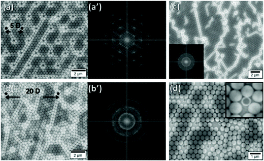 | ||
| Fig. 18 Particle monolayers templated using substrates patterned with pillars showing the impact of pillar spacing and mismatching pillar size (a) Good size matching between pillars and particles with small interpillar spacings (5D) produce hexagonal close-packed lattices with ordered 2D Fourier transforms (a′). (b) Good size matching between pillars and particles with large interpillar spacings (20D) produce more disordered lattices with rings in the 2D Fourier transforms (b′). (c) Template free deposition produces poly disordered lattices with many distinct domains. (d) Using smaller pillars (296 nm) leads to the formation of lattice defects. Figure reproduced with permission from ref. 225. Copyright 2014 Beilstein-Institut. | ||
7. Perspectives
Both dip-coating and drag-coating offer additional parameters to those discussed above, which have yet to be fully investigated for their effect on disorder in colloidal films. Specifically, solvent properties, such as viscosity and surface tension, will have significant consequences on particle assembly. Solvent properties are apt to create disorder on scales larger than the particle, for instance generating irregular gaps and non-linear banding. This type of patterning can be caused due to Marangoni flows.Of all the systems discussed, topographically patterned substrates offer the greatest degree of control over spatial and rotational disorder. However, most topographically patterned substrates use lithographic techniques that limit their scalability. Introducing a pattern using nanoimprint lithography offers a route to bulk production of substrates with tailored disorder. The effects of disorder achieved in these systems on their optical properties has not been investigated thoroughly in the literature. Clearly, there is great potential in these techniques for creating systems with near-complete control of the spatial and rotational disorder. This would allow us to fully explore the impact of disorder on the optical properties of two-dimensional colloidal assemblies.
Another frontier that remains largely unexplored is hierarchical disorder. For instance, in binary mixtures of particles, disorder can occur in particles of one size, while not impacting the crystallinity of a second population of particles, allowing interactions with waves to be highly tuned.
Inexistant to date, is the use of non-flat surfaces to influence disorder in convective assembly. Here substrate curvature, applied post-synthetically, could be used to introduce lattice defects and vary correlation distance within assembled films.
Post-synthetic techniques using mechanical forces, including among others, strain, shear, and scratching, are promising routes to control disorder.231 Flexible substrates can potentially produce surfaces over which correlation distances could be dynamically changed.
In this review we have extensively discussed particle assemblies, but other structures can be created using evaporative processes. Monolayer perforated films can be made with interesting angle-dependent appearances (Fig. 19).232 We previously produced such films, showing how salt and surfactant concentration, relative humidity and withdrawal speed all impacted perforation density and size, and thus film appearance. The degree of disorder in the macroperforations was affected by the type of salt used (Fig. 19), certainly other parameters could also be explored in terms of their impact on order regulating dewetting. By comparison, topographical patterning offers highly precise control through capillary forces in confined spaces. Of particular interest, is the potential of topological patterning to manage disorder in non-close packed systems, where both rotational and positional control can be exerted with high accuracy.
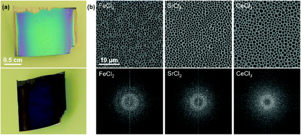 | ||
| Fig. 19 (a) Photographs of a microperforated film at two different angles. (b) SEM micrographs of macroperforations made by using different salts and their fast Fourier transforms showing differences in the degree of order and the distance between perforations. The scale is the same for all micrographs. Figure adapted with permission from ref. 232. Copyright 2014 John Wiley & Sons. | ||
8. Conclusions
Currently, most examples of disorder in convectively assembled systems appear in studies which aim to create organized close-packed particle assemblies. Historically disorder has been seen as undesirable, more recently however, a controllable degree of disorder has proved advantageous for some applications, particularly in optics. We can reverse engineer the lessons learned from optimizing order in colloidal films to find the parameters impacting disorder. In this review, we have presented the main contributions in terms of the particle, solvent, and substrate properties affecting particle organization during convective assembly.To have a good control over particle placement, many of the same considerations are needed to achieve disorder as those required for obtaining crystallinity: excellent wettability, strongly repulsive interparticle and particle–substrate forces, high evaporative flux, and good particle mobility. Conversely, polydispersity in size and shape, a mismatch between particles and templates, and polymodal particle populations, which are harmful to close packing, can be used to tailor the degree of disorder.
In general, drag-coating gives better control of particle assembly than dip-coating, but is less amenable to coating curved surfaces and large areas. Spheres are the easiest objects to assemble, as orientational disorder does not need to be considered, and preferential packing between certain faces does not occur. However, irrespective of shape, disorder can be managed.
We can target very specific particle distributions through substrate patterning. During convective assembly, chemical patterning gives approximate control within specific regions by regulating dewetting. By comparison, topographical patterning offers highly precise control through capillary forces in confined spaces. Of particular interest, is the potential of topological patterning to manage disorder in non-close packed systems, where both rotational and positional control can be exerted with high accuracy.
Author contributions
LR, AH, KV, and GLD were involved in writing of the original draft and visualization. PL, ED, MTD, KV, and GLD were involved in supervision and funding acquisition. LR and GLD were responsible for project administration. All authors were involved in the reviewing and editing of the final manuscript.Conflicts of interest
The authors declare no conflicts of interest.Acknowledgements
LR and GLD received funding for this work from the European Research Council (ERC) under European Union's Horizon 2020 research and innovation programme (grant no. 948319). LR, GLD, ED, and MTD received financial support from the Conseil Régional d'Aquitaine and the LabEx AMADEus (grant no. ANR-10-LABX-42) in the framework of IdEx Bordeaux (grant no. ANR-10-IDEX-03-02) managed by the National Agency for Research. AH, PL, ED, MTD, KV, and GLD received financial support from the Centre National de la Recherche Scientifique (CNRS) through the MITI interdisciplinary programs and from the ANR (grant no. ANR-19-CE09-0014). AH also received support from the Light S&T Graduate Program (PIA3 Investment for the Future Program, grant no. ANR-17-EURE-0027).References
- V. Tuchin, Tissue Optics: Light Scattering Methods and Instruments for Medical Diagnosis, SPIE Press, 2015 Search PubMed.
- M. I. Mishchenko, J. W. Hovenier and L. D. Travis, Light Scattering by Nonspherical Particles: Theory, Measurements, and Applications, Elsevier Science, 1999 Search PubMed.
- D. S. Wiersma, Nat. Photonics, 2013, 7, 188 CrossRef CAS.
- R. Carminati and J. C. Schotland, Principles of Scattering and Transport of Light, Cambridge University Press, 2021 Search PubMed.
- M. Florescu, S. Torquato and P. J. Steinhardt, Proc. Natl. Acad. Sci. U. S. A., 2009, 106, 20658 CrossRef CAS PubMed.
- L. F. Rojas-Ochoa, J. M. Mendez-Alcaraz, J. J. Sáenz, P. Schurtenberger and F. Scheffold, Phys. Rev. Lett., 2004, 93, 073903 CrossRef CAS PubMed.
- F. Riboli, N. Caselli, S. Vignolini, F. Intonti, K. Vynck, P. Barthelemy, A. Gerardino, L. Balet, L. H. Li, A. Fiore, M. Gurioli and D. S. Wiersma, Nat. Mater., 2014, 13, 720 CrossRef CAS PubMed.
- H. Noh, J.-K. Yang, S. F. Liew, M. J. Rooks, G. S. Solomon and H. Cao, Phys. Rev. Lett., 2011, 106, 183901 CrossRef PubMed.
- L. Sapienza, H. Thyrrestrup, S. Stobbe, P. D. Garcia, S. Smolka and P. Lodahl, Science, 2010, 327, 1352 CrossRef CAS PubMed.
- S. Yu, C.-W. Qiu, Y. Chong, S. Torquato and N. Park, Nat. Rev. Mater., 2021, 6, 226 CrossRef CAS.
- M. Rothammer, C. Zollfrank, K. Busch and G. von Freymann, Adv. Opt. Mater., 2021, 9, 2100787 CrossRef CAS.
- K. Vynck, R. Pierrat, R. Carminati, L. S. Froufe-Pérez, F. Scheffold, R. Sapienza, S. Vignolini and J. J. Sáenz, 2021, arXiv:2106.13892.
- H. Brumberger, Modern Aspects of Small-Angle Scattering, Springer, Netherlands, 2013 Search PubMed.
- S. G. Romanov, S. Orlov, D. Ploss, C. K. Weiss, N. Vogel and U. Peschel, Sci. Rep., 2016, 6, 27264 CrossRef CAS PubMed.
- R. O. Prum and R. Torres, J. Exp. Biol., 2003, 206, 2409 CrossRef PubMed.
- J. Haberko, L. S. Froufe-Pérez and F. Scheffold, Nat. Commun., 2020, 11, 4867 CrossRef CAS PubMed.
- L. Tsang, J. A. Kong and K. H. Ding, Scattering of Electromagnetic Waves: Theories and Applications, Wiley, 2004 Search PubMed.
- C. Battaglia, K. Söderström, J. Escarré, F.-J. Haug, D. Dominé, P. Cuony, M. Boccard, G. Bugnon, C. Denizot, M. Despeisse, A. Feltrin and C. Ballif, Appl. Phys. Lett., 2010, 96, 213504 CrossRef.
- C. Rockstuhl, S. Fahr, K. Bittkau, T. Beckers, R. Carius, F.-J. Haug, T. Söderström, C. Ballif and F. Lederer, Opt. Express, 2010, 18, A335 CrossRef CAS PubMed.
- P. Kowalczewski, M. Liscidini and L. C. Andreani, Opt. Lett., 2012, 37, 4868 CrossRef CAS PubMed.
- Y. J. Donie, D. Theobald, S. Moghadamzadeh, A. Mertens, I. M. Hossain, U. W. Paetzold, U. Lemmer and G. Gomard, Adv. Opt. Mater., 2021, 9, 2001610 CrossRef CAS.
- M. E. Stewart, C. R. Anderton, L. B. Thompson, J. Maria, S. K. Gray, J. A. Rogers and R. G. Nuzzo, Chem. Rev., 2008, 108, 494 CrossRef CAS PubMed.
- R. Brunner, O. Sandfuchs, C. Pacholski, C. Morhard and J. Spatz, Laser Photonics Rev., 2012, 6, 641 CrossRef.
- D. Bedeaux and J. Vlieger, Optical Properties of Surfaces, Imperial College Press, 2004 Search PubMed.
- S. Grésillon, L. Aigouy, A. C. Boccara, J. C. Rivoal, X. Quelin, C. Desmarest, P. Gadenne, V. A. Shubin, A. K. Sarychev and V. M. Shalaev, Phys. Rev. Lett., 1999, 82, 4520 CrossRef.
- A. Moreau, C. Ciracì, J. J. Mock, R. T. Hill, Q. Wang, B. J. Wiley, A. Chilkoti and D. R. Smith, Nature, 2012, 492, 86 CrossRef CAS PubMed.
- P. R. Wray and H. A. Atwater, ACS Photonics, 2020, 7, 2105 CrossRef CAS.
- A. Jouanin, J. P. Hugonin and P. Lalanne, Adv. Funct. Mater., 2016, 26, 6215–6223 CrossRef CAS.
- M. Albooyeh, S. Kruk, C. Menzel, C. Helgert, M. Kroll, A. Krysinski, M. Decker, D. N. Neshev, T. Pertsch, C. Etrich, C. Rockstuhl, S. A. Tretyakov, C. R. Simovski and Y. S. Kivshar, Sci. Rep., 2014, 4, 4484 CrossRef CAS PubMed.
- M. Jang, Y. Horie, A. Shibukawa, J. Brake, Y. Liu, S. M. Kamali, A. Arbabi, H. Ruan, A. Faraon and C. Yang, Nat. Photonics, 2018, 12, 84 CrossRef CAS PubMed.
- M. Dupré, L. Hsu and B. Kanté, Sci. Rep., 2018, 8, 7162 CrossRef PubMed.
- H. Bertin, Y. Brûlé, G. Magno, T. Lopez, P. Gogol, L. Pradere, B. Gralak, D. Barat, G. Demésy and B. Dagens, ACS Photonics, 2018, 5, 2661 CrossRef CAS.
- E. El Shamy, J. Jaeck, R. Haïdar and P. Bouchon, Appl. Phys. Lett., 2019, 115, 041103 CrossRef.
- H. Zhang, Q. Cheng, H. Chu, O. Christogeorgos, W. Wu and Y. Hao, Appl. Phys. Lett., 2021, 118, 101601 CrossRef CAS.
- P. M. Piechulla, B. Fuhrmann, E. Slivina, C. Rockstuhl, R. B. Wehrspohn and A. N. Sprafke, Adv. Opt. Mater., 2021, 9, 2100186 CrossRef CAS.
- F. Sterl, E. Herkert, S. Both, T. Weiss and H. Giessen, ACS Nano, 2021, 15, 10318 CrossRef PubMed.
- P. Mao, C. Liu, X. Li, M. Liu, Q. Chen, M. Han, S. A. Maier, E. H. Sargent and S. Zhang, Light: Sci. Appl., 2021, 10, 180 CrossRef CAS PubMed.
- F. Kretschmer, S. Mühlig, S. Hoeppener, A. Winter, M. D. Hager, C. Rockstuhl, T. Pertsch and U. S. Schubert, Part. Part. Syst. Charact., 2014, 31, 721–744 CrossRef.
- M. L. De Marco, S. Semlali, B. A. Korgel, P. Barois, G. L. Drisko and C. Aymonier, Angew. Chem., Int. Ed., 2018, 57, 4478–4498 CrossRef PubMed.
- X. Lu, M. Rycenga, S. E. Skrabalak, B. Wiley and Y. Xia, Annu. Rev. Phys. Chem., 2009, 60, 167–192 CrossRef CAS PubMed.
- Z. Wu, S. Yang and W. Wu, Nanoscale, 2016, 8, 1237–1259 RSC.
- S. Kumar and T. Nann, Small, 2006, 2, 316–329 CrossRef CAS PubMed.
- D. A. Keen and A. L. Goodwin, Nature, 2015, 521, 303–309 CrossRef CAS PubMed.
- P. M. Ossi, Disordered Materials - An Introduction, Springer-Verlag, Berlin Heidelberg, 2006 Search PubMed.
- V. Lotito and T. Zambelli, Adv. Colloid Interface Sci., 2017, 246, 217 CrossRef CAS PubMed.
- V. Lotito and T. Zambelli, Adv. Colloid Interface Sci., 2020, 284, 102252 CrossRef CAS PubMed.
- C. P. Martin, M. O. Blunt, E. Pauliac-Vaujour, A. Stannard, P. Moriarty, I. Vancea and U. Thiele, Phys. Rev. Lett., 2007, 99, 116103 CrossRef PubMed.
- E. Armstrong, W. Khunsin, M. Osiak, M. Blömker, C. M. S. Torres and C. O'Dwyer, Small, 2014, 10, 1895 CrossRef CAS PubMed.
- J. C. Earnshaw and D. J. Robinson, J. Phys.: Condens. Matter, 1990, 2, 9199 CrossRef CAS.
- H. J. Schöpe, J. Phys.: Condens. Matter, 2003, 15, L533 CrossRef.
- I. M. Krieger and F. M. O'Neill, J. Am. Chem. Soc., 1968, 90, 3114 CrossRef CAS.
- S. A. Asher, J. M. Weissman, A. Tikhonov, R. D. Coalson and R. Kesavamoorthy, Phys. Rev. E, 2004, 69, 066619 CrossRef PubMed.
- A. Tikhonov, R. D. Coalson and S. A. Asher, Phys. Rev. B: Condens. Matter Mater. Phys., 2008, 77, 235404 CrossRef PubMed.
- C. Deleuze, B. Sarrat, F. Ehrenfeld, S. Perquis, C. Derail and L. Billon, Phys. Chem. Chem. Phys., 2011, 13, 10681 RSC.
- M. Klokkenburg, B. H. Erné, A. Wiedenmann, A. V. Petukhov and A. P. Philipse, Phys. Rev. E, 2007, 75, 051408 CrossRef CAS PubMed.
- A. Wiedenmann, M. Kammel, A. Heinemann and U. Keiderling, J. Phys.: Condens. Matter, 2006, 18, S2713 CrossRef CAS.
- J. Li, B. Cabane, M. Sztucki, J. Gummel and L. Goehring, Langmuir, 2012, 28, 200 CrossRef CAS PubMed.
- M. Megens, C. M. van Kats, P. Bösecke and W. L. Vos, Langmuir, 1997, 13, 6120 CrossRef CAS.
- P. Siffalovic, E. Majkova, L. Chitu, M. Jergel, S. Luby, A. Satka and S. V. Roth, Phys. Rev. B: Condens. Matter Mater. Phys., 2007, 76, 195432 CrossRef.
- A. C. Y. Liu, R. F. Tabor, M. D. de Jonge, S. T. Mudie and T. C. Petersen, Proc. Natl. Acad. Sci. U. S. A., 2017, 114, 10344 CrossRef CAS PubMed.
- L. Wu, X. Wang, G. Wang and G. Chen, Nat. Commun., 2018, 9, 1335 CrossRef PubMed.
- P. Huber, T. Blättler, M. Textor, W. Leitenberger, U. Pietsch and T. Geue, Colloids Surf., A, 2008, 321, 113 CrossRef CAS.
- K. Vegso, M. Jergel, P. Siffalovic, M. Kotlar, Y. Halahovets, M. Hodas, M. Pelletta and E. Majkova, Sens. Actuators, A, 2016, 241, 87 CrossRef CAS.
- P. Huber, O. Bunk, U. Pietsch, M. Textor and T. Geue, J. Phys. Chem. B, 2010, 114, 12473 CrossRef CAS PubMed.
- M. A. Schroer, C. Gutt, F. Lehmkühler, B. Fischer, I. Steinke, F. Westermeier, M. Sprung and G. Grübel, Soft Matter, 2015, 11, 5465 RSC.
- D. N. ten Napel, J.-M. Meijer and A. V. Petukhov, Appl. Sci., 2021, 11, 5117 CrossRef CAS.
- M. Quesada-Pérez, A. Moncho-Jordá, F. Martínez-López and R. Hidalgo-Álvarez, J. Chem. Phys., 2001, 115, 10897 CrossRef.
- P. Batys, M. Nosek and P. Weroński, Appl. Surf. Sci., 2015, 332, 327 CrossRef.
- L. Zaidouny, T. Bohlein, R. Roth and C. Bechinger, Soft Matter, 2013, 9, 9230 RSC.
- S. C. Rödner, P. Wedin and L. Bergström, Langmuir, 2002, 18, 9327 CrossRef.
- V. Senthil Kumar and V. Kumaran, J. Chem. Phys., 2005, 123, 114501 CrossRef PubMed.
- V. Lotito and T. Zambelli, Nanomaterials, 2019, 9, 921 CrossRef CAS PubMed.
- D. Weaire and N. Rivier, Contemp. Phys., 1984, 25, 59 CrossRef.
- I. Buttinoni, M. Steinacher, H. T. Spanke, J. Pokki, S. Bahmann, B. Nelson, G. Foffi and L. Isa, Phys. Rev. E, 2017, 95, 012610 CrossRef PubMed.
- A. T. Gray, E. Mould, C. P. Royall and I. Williams, J. Phys.: Condens. Matter, 2015, 27, 194108 CrossRef PubMed.
- P. J. Steinhardt, D. R. Nelson and M. Ronchetti, Phys. Rev. B: Condens. Matter Mater. Phys., 1983, 28, 784 CrossRef CAS.
- C. A. Murray, in Bond-Orientational Order in Condensed Matter Systems, ed. K. J. Strandburg, Springer, New York, NY, 1992, p. 137 Search PubMed.
- P. Dillmann, G. Maret and P. Keim, J. Phys.: Condens. Matter, 2012, 24, 464118 CrossRef PubMed.
- K. J. Strandburg, in Bond-Orientational Order in Condensed Matter Systems, ed. K. J. Strandburg, Springer, New York, NY, 1992, p. 32 Search PubMed.
- D. R. Nelson and B. I. Halperin, Phys. Rev. B: Condens. Matter Mater. Phys., 1979, 19, 2457 CrossRef CAS.
- S. Ramananarivo, E. Ducrot and J. Palacci, Nat. Commun., 2019, 10, 3380 CrossRef PubMed.
- Y. Kusaka, N. Ishida and H. Ushijima, Soft Matter, 2013, 9, 3155 RSC.
- E. Locatelli and E. Bianchi, Soft Matter, 2018, 14, 8119 RSC.
- Z. Guo, P. Wu and J. T. Kindt, Soft Matter, 2019, 15, 1027 RSC.
- E. Tamborini, C. P. Royall and P. Cicuta, J. Phys.: Condens. Matter, 2015, 27, 194124 CrossRef PubMed.
- X. Qi, Y. Chen, Y. Jin and Y.-H. Yang, J. Korean Phys. Soc., 2006, 49, 1682 CAS.
- P. Kumnorkaew, Y.-K. Ee, N. Tansu and J. F. Gilchrist, Langmuir, 2008, 24, 12150 CrossRef CAS PubMed.
- A. J. Armstrong, R. C. Mockler and W. J. O'Sullivan, J. Phys.: Condens. Matter, 1989, 1, 1707 CrossRef CAS.
- A. L. Thorneywork, J. L. Abbott, D. G. A. L. Aarts, P. Keim and R. P. A. Dullens, J. Phys.: Condens. Matter, 2018, 30, 104003 CrossRef PubMed.
- R. Aslam, S. Ardanza-Trevijano, K. M. Poduska, A. Yethiraj and W. González-Viñas, Phys. Rev. E, 2017, 95, 032607 CrossRef PubMed.
- W. Mickel, S. C. Kapfer, G. E. Schröder-Turk and K. Mecke, J. Chem. Phys., 2013, 138, 044501 CrossRef PubMed.
- P. Bagheri, A. M. Almudallal, A. Yethiraj and K. M. Poduska, Langmuir, 2015, 31, 8251 CrossRef CAS PubMed.
- P. Bagheri, A. M. Almudallal, A. Yethiraj and K. M. Poduska, Langmuir, 2016, 32, 2524 CrossRef CAS PubMed.
- A. Yethiraj, A. Wouterse, B. Groh and A. van Blaaderen, Phys. Rev. Lett., 2004, 92, 058301 CrossRef PubMed.
- J.-M. Meijer, V. Meester, F. Hagemans, H. N. W. Lekkerkerker, A. P. Philipse and A. V. Petukhov, Langmuir, 2019, 35, 4946 CrossRef CAS PubMed.
- M. Kramár, A. Goullet, L. Kondic and K. Mischaikow, Phys. Rev. E, 2013, 87, 042207 CrossRef PubMed.
- M. Kramár, A. Goullet, L. Kondic and K. Mischaikow, Phys. Rev. E, 2014, 90, 052203 CrossRef PubMed.
- M. Kramár, A. Goullet, L. Kondic and K. Mischaikow, Phys. D, 2014, 283, 37 CrossRef.
- S. Ardanza-Trevijano, I. Zuriguel, R. Arévalo and D. Maza, Phys. Rev. E, 2014, 89, 052212 CrossRef CAS PubMed.
- V. Robins and K. Turner, Phys. D, 2016, 334, 99 CrossRef.
- L. Malaquin, T. Kraus, H. Schmid, E. Delamarche and H. Wolf, Langmuir, 2007, 23, 11513 CrossRef CAS PubMed.
- J. Gao, S. Semlali, J. Hunel, D. Montero, Y. Battie, D. Gonzalez-Rodriguez, R. Oda, G. L. Drisko and E. Pouget, Chem. Mater., 2020, 32, 821 CrossRef CAS.
- D. Noguera-Marín, C. L. Moraila-Martínez, M. Cabrerizo-Vílchez and M. A. Rodríguez-Valverde, Eur. Phys. J. A, 2016, 39, 20 Search PubMed.
- A. S. Dimitrov and K. Nagayama, Langmuir, 1996, 12, 1303 CrossRef CAS.
- G. Jing, H. Bodiguel, F. Doumenc, E. Sultan and B. Guerrier, Langmuir, 2010, 26, 2288 CrossRef CAS PubMed.
- J. J. Diao and M. G. Xia, Colloids Surf., A, 2009, 338, 167 CrossRef CAS.
- S. Watanabe, K. Inukai, S. Mizuta and M. T. Miyahara, Langmuir, 2009, 25, 7287 CrossRef CAS PubMed.
- H. Bodiguel, F. Doumenc and B. Guerrier, Langmuir, 2010, 26, 10758 CrossRef CAS PubMed.
- L. Landau and B. Levich, Acta Physicochim. URSS, 1942, 17, 42 Search PubMed.
- B. Derjaguin, Acta Physicochim. URSS, 1945, 20, 349 Search PubMed.
- S. Palma and H. Lhuissier, J. Fluid Mech., 2019, 869, R3 CrossRef CAS.
- G. Berteloot, A. Daerr, F. Lequeux and L. Limat, Chem. Eng. Process., 2013, 68, 69 CrossRef CAS.
- N. A. Fleck, R. M. McMeeking and T. Kraus, Langmuir, 2015, 31, 13655 CrossRef CAS PubMed.
- K. W. Tan, G. Li, Y. K. Koh, Q. Yan and C. C. Wong, Langmuir, 2008, 24, 9273 CrossRef CAS PubMed.
- J. Zhang, H. Liu, Z. Wang and N. Ming, J. Appl. Phys., 2008, 103, 013517 CrossRef.
- T. Alfrey, E. B. Bradford, J. W. Vanderhoff and G. Oster, J. Opt. Soc. Am., 1954, 44, 603 CrossRef CAS.
- V. N. Truskett and K. J. Stebe, Langmuir, 2003, 19, 8271 CrossRef CAS.
- L. V. Govor, G. Reiter, J. Parisi and G. H. Bauer, Phys. Rev. E, 2004, 69, 061609 CrossRef PubMed.
- D. M. Kuncicky and O. D. Velev, Langmuir, 2008, 24, 1371 CrossRef CAS PubMed.
- T. P. Bigioni, X.-M. Lin, T. T. Nguyen, E. I. Corwin, T. A. Witten and H. M. Jaeger, Nat. Mater., 2006, 5, 265 CrossRef CAS PubMed.
- H. Hu and R. G. Larson, in Evaporative Self-Assembly of Ordered Complex Structures, World Scientific, 2011, p. 1 Search PubMed.
- R. D. Deegan, O. Bakajin, T. F. Dupont, G. Huber, S. R. Nagel and T. A. Witten, Nature, 1997, 389, 827 CrossRef CAS.
- C. D. Dushkin, H. Yoshimura and K. Nagayama, Chem. Phys. Lett., 1993, 204, 455 CrossRef CAS.
- R. Bhardwaj, X. Fang, P. Somasundaran and D. Attinger, Langmuir, 2010, 26, 7833 CrossRef CAS PubMed.
- M. Majumder, C. S. Rendall, J. A. Eukel, J. Y. L. Wang, N. Behabtu, C. L. Pint, T.-Y. Liu, A. W. Orbaek, F. Mirri, J. Nam, A. R. Barron, R. H. Hauge, H. K. Schmidt and M. Pasquali, J. Phys. Chem. B, 2012, 116, 6536 CrossRef CAS PubMed.
- K. N. Al-Milaji and H. Zhao, J. Phys. Chem. C, 2019, 123, 12029 CrossRef CAS.
- A. Vital, M. Vayer, T. Tillocher, R. Dussart, M. Boufnichel and C. Sinturel, Appl. Surf. Sci., 2017, 393, 127 CrossRef CAS.
- M. H. Patel, T. K. Chaudhuri, V. K. Patel, T. Shripathi, U. Deshpande and N. P. Lalla, RSC Adv., 2017, 7, 4422 RSC.
- G. W. Kim, E. H. Kwon, M. Kim and Y. D. Park, J. Phys. Chem. C, 2019, 123, 23255 CrossRef CAS.
- D. Quéré, A. de Ryck and O. O. Ramdane, EPL, 1997, 37, 305 CrossRef.
- A. Q. Shen, B. Gleason, G. H. McKinley and H. A. Stone, Phys. Fluids, 2002, 14, 4055 CrossRef CAS.
- R. Krechetnikov and G. M. Homsy, J. Fluid Mech., 2006, 559, 429 CrossRef.
- R. Krechetnikov and G. M. Homsy, Phys. Fluids, 2005, 17, 102108 CrossRef.
- J. Delacotte, L. Montel, F. Restagno, B. Scheid, B. Dollet, H. A. Stone, D. Langevin and E. Rio, Langmuir, 2012, 28, 3821 CrossRef CAS PubMed.
- M. H. Kim, H. K. Choi, O. O. Park and S. H. Im, Appl. Phys. Lett., 2006, 88, 143127 CrossRef.
- K. Nagayama, Colloids Surf., A, 1996, 109, 363 CrossRef CAS.
- E. Bindini, G. Naudin, M. Faustini, D. Grosso and C. Boissière, J. Phys. Chem. C, 2017, 121, 14572 CrossRef CAS.
- G. J. A. A. Soler-Illia, P. C. Angelomé, M. C. Fuertes, D. Grosso and C. Boissiere, Nanoscale, 2012, 4, 2549 RSC.
- L. Cademartiri, A. Sutti, G. Calestani, C. Dionigi, P. Nozar and A. Migliori, Langmuir, 2003, 19, 7944 CrossRef CAS.
- D. D. Brewer, T. Shibuta, L. Francis, S. Kumar and M. Tsapatsis, Langmuir, 2011, 27, 11660 CrossRef CAS PubMed.
- H. Ko, H.-W. Lee and J. Moon, Thin Solid Films, 2004, 447, 638 CrossRef.
- E. Adachi and K. Nagayama, Langmuir, 1996, 12, 1836 CrossRef CAS.
- E. Adachi and K. Nagayama, Adv. Biophys., 1997, 34, 81 CrossRef CAS PubMed.
- Z. Yuan, D. N. Petsev, B. G. Prevo, O. D. Velev and P. Atanassov, Langmuir, 2007, 23, 5498 CrossRef CAS PubMed.
- M. Le Berre, Y. Chen and D. Baigl, Langmuir, 2009, 25, 2554 CrossRef CAS PubMed.
- C.-Y. Cai, K.-Y. A. Lin and H. Yang, Appl. Phys. Lett., 2014, 105, 201913 CrossRef.
- J. Ouyang, T.-F. Guo, Y. Yang, H. Higuchi, M. Yoshioka and T. Nagatsuka, Adv. Mater., 2002, 14, 915 CrossRef CAS.
- E. Pérez-Gutiérrez, J. Lozano, J. Gaspar-Tánori, J.-L. Maldonado, B. Gómez, L. López, L.-F. Amores-Tapia, O. Barbosa-García and M.-J. Percino, Sol. Energy, 2017, 146, 79 CrossRef.
- S. Matsushita, T. Miwa and A. Fujishima, Langmuir, 1997, 13, 2582 CrossRef CAS.
- B. G. Prevo and O. D. Velev, Langmuir, 2004, 20, 2099 CrossRef CAS PubMed.
- H. Yang and P. Jiang, Langmuir, 2010, 26, 13173 CrossRef CAS PubMed.
- K. Chen, S. V. Stoianov, J. Bangerter and H. D. Robinson, J. Colloid Interface Sci., 2010, 344, 315 CrossRef CAS PubMed.
- A. D. Ormonde, E. C. M. Hicks, J. Castillo and R. P. Van Duyne, Langmuir, 2004, 20, 6927 CrossRef CAS PubMed.
- M. Mittal, R. K. Niles and E. M. Furst, Nanoscale, 2010, 2, 2237 RSC.
- P. Born, S. Blum, A. Munoz and T. Kraus, Langmuir, 2011, 27, 8621 CrossRef CAS PubMed.
- J. S. Jenkins, M. C. Flickinger and O. D. Velev, Coatings, 2013, 3, 26 CrossRef CAS.
- K. Joshi, T. Muangnapoh, M. D. Stever and J. F. Gilchrist, Langmuir, 2015, 31, 12348 CrossRef CAS PubMed.
- T. Muangnapoh, A. L. Weldon and J. F. Gilchrist, Appl. Phys. Lett., 2013, 103, 181603 CrossRef.
- A. L. Weldon, PhD Thesis, Lehigh University, 2014.
- T. Muangnapoh, PhD Thesis, Lehigh University, 2015.
- S. Das, E. M. Duraia, O. D. Velev, J. R. Gatabi and G. W. Beall, Surf. Coat. Technol., 2017, 319, 353 CrossRef CAS.
- D. J. Lacks and J. R. Wienhoff, J. Chem. Phys., 1999, 111, 398 CrossRef CAS.
- B. Cabane, J. Li, F. Artzner, R. Botet, C. Labbez, G. Bareigts, M. Sztucki and L. Goehring, Phys. Rev. Lett., 2016, 116, 208001 CrossRef PubMed.
- C. Y. Lau and W. B. Russel, AlChE J., 2014, 60, 1287 CrossRef CAS.
- A. S. Dimitrov, T. Miwa and K. Nagayama, Langmuir, 1999, 15, 5257 CrossRef CAS.
- G. B. Jeffery and L. N. G. Filon, Proc.: Math., Phys. Eng. Sci., 1922, 102, 161 Search PubMed.
- D. M. Kuncicky, B. G. Prevo and O. D. Velev, J. Mater. Chem., 2006, 16, 1207–1211 RSC.
- S. Thiemann, M. Gruber, I. Lokteva, J. Hirschmann, M. Halik and J. Zaumseil, ACS Appl. Mater. Interfaces, 2013, 5, 1656 CrossRef CAS PubMed.
- R. Srikantharajah, T. Schindler, I. Landwehr, S. Romeis, T. Unruh and W. Peukert, Nanoscale, 2016, 8, 19882 RSC.
- V. R. Dugyala and M. G. Basavaraj, RSC Adv., 2015, 5, 60079 RSC.
- H. Shimoda, S. J. Oh, H. Z. Geng, R. J. Walker, X. B. Zhang, L. E. McNeil and O. Zhou, Adv. Mater., 2002, 14, 899 CrossRef CAS.
- M. E. Spotnitz, D. Ryan and H. A. Stone, J. Mater. Chem., 2004, 14, 1299 RSC.
- P. Atanasova, N. Stitz, S. Sanctis, J. H. M. Maurer, R. C. Hoffmann, S. Eiben, H. Jeske, J. J. Schneider and J. Bill, Langmuir, 2015, 31, 3897 CrossRef CAS PubMed.
- J.-M. Meijer, F. Hagemans, L. Rossi, D. V. Byelov, S. I. R. Castillo, A. Snigirev, I. Snigireva, A. P. Philipse and A. V. Petukhov, Langmuir, 2012, 28, 7631 CrossRef CAS PubMed.
- C. L. Moraila-Martínez, M. A. Cabrerizo-Vílchez and M. A. Rodríguez-Valverde, Soft Matter, 2013, 9, 1664 RSC.
- A. Askounis, K. Sefiane, V. Koutsos and M. E. R. Shanahan, Colloids Surf., A, 2014, 441, 855 CrossRef CAS.
- M. J. Pavan and R. Shenhar, J. Mater. Chem., 2011, 21, 2028 RSC.
- N. Vogel, M. Retsch, C.-A. Fustin, A. del Campo and U. Jonas, Chem. Rev., 2015, 115, 6265 CrossRef CAS PubMed.
- O. Kletenik-Edelman, C. G. Sztrum-Vartash and E. Rabani, J. Mater. Chem., 2009, 19, 2872 RSC.
- J. Tien, A. Terfort and G. M. Whitesides, Langmuir, 1997, 13, 5349 CrossRef CAS.
- C. von Bojnicic-Kninski, R. Popov, E. Dörsam, F. F. Loeffler, F. Breitling and A. Nesterov-Mueller, Adv. Funct. Mater., 2017, 27, 1703511 CrossRef.
- C.-A. Fustin, G. Glasser, H. W. Spiess and U. Jonas, Adv. Mater., 2003, 15, 1025 CrossRef CAS.
- Y. Masuda, T. Itoh and K. Koumoto, Langmuir, 2005, 21, 4478 CrossRef CAS PubMed.
- Q. Guo, C. Arnoux and R. E. Palmer, Langmuir, 2001, 17, 7150 CrossRef CAS.
- W. M. Choi and O. O. Park, Colloids Surf., A, 2006, 277, 131 CrossRef CAS.
- B. Viallet, L. Ressier, L. Czornomaz and N. Decorde, Langmuir, 2010, 26, 4631 CrossRef CAS PubMed.
- C. Belgardt, T. Blaudeck, C. von Borczyskowski and H. Graaf, Adv. Eng. Mater., 2014, 16, 1090 CrossRef CAS.
- C.-A. Fustin, G. Glasser, H. W. Spiess and U. Jonas, Langmuir, 2004, 20, 9114 CrossRef CAS PubMed.
- C. Yi, Y. Yang, B. Liu, J. He and Z. Nie, Chem. Soc. Rev., 2020, 49, 465 RSC.
- S. B. Darling, Prog. Polym. Sci., 2007, 32, 1152 CrossRef CAS.
- M. R. Bockstaller, Y. Lapetnikov, S. Margel and E. L. Thomas, J. Am. Chem. Soc., 2003, 125, 5276 CrossRef CAS PubMed.
- R. J. Spontak, R. Shankar, M. K. Bowman, A. S. Krishnan, M. W. Hamersky, J. Samseth, M. R. Bockstaller and K. Ø. Rasmussen, Nano Lett., 2006, 6, 2115 CrossRef CAS PubMed.
- A. Horechyy, B. Nandan, N. E. Zafeiropoulos, P. Formanek, U. Oertel, N. C. Bigall, A. Eychmüller and M. Stamm, Adv. Funct. Mater., 2013, 23, 483 CrossRef CAS.
- Q. Li, J. He, E. Glogowski, X. Li, J. Wang, T. Emrick and T. P. Russell, Adv. Mater., 2008, 20, 1462 CrossRef CAS.
- V. Flauraud, M. Mastrangeli, G. D. Bernasconi, J. Butet, D. T. L. Alexander, E. Shahrabi, O. J. F. Martin and J. Brugger, Nat. Nanotechnol., 2017, 12, 73 CrossRef CAS PubMed.
- T. Kraus, L. Malaquin, H. Schmid, W. Riess, N. D. Spencer and H. Wolf, Nat. Nanotechnol., 2007, 2, 570 CrossRef CAS PubMed.
- C. Lu, H. Möhwald and A. Fery, Soft Matter, 2007, 3, 1530 RSC.
- A. Mathur, A.-D. Brown and J. Erlebacher, Langmuir, 2006, 22, 582 CrossRef CAS PubMed.
- S. Ni, H. Wolf and L. Isa, Langmuir, 2018, 34, 2481 CrossRef CAS PubMed.
- T. Kraus, L. Malaquin, E. Delamarche, H. Schmid, N. D. Spencer and H. Wolf, Adv. Mater., 2005, 17, 2438 CrossRef CAS.
- V. Liberman, C. Yilmaz, T. M. Bloomstein, S. Somu, Y. Echegoyen, A. Busnaina, S. G. Cann, K. E. Krohn, M. F. Marchant and M. Rothschild, Adv. Mater., 2010, 22, 4298 CrossRef CAS PubMed.
- M. Asbahi, F. Wang, Z. Dong, J. K. W. Yang and K. S. L. Chong, Nanotechnology, 2016, 27, 424001 CrossRef PubMed.
- V. Sharma, D. Xia, C. C. Wong, W. C. Carter and Y.-M. Chiang, J. Mater. Res., 2011, 26, 247 CrossRef CAS.
- C. Kuemin, R. Stutz, N. D. Spencer and H. Wolf, Langmuir, 2011, 27, 6305 CrossRef CAS PubMed.
- M. Juodėnas, T. Tamulevičius, J. Henzie, D. Erts and S. Tamulevičius, ACS Nano, 2019, 13, 9038 CrossRef PubMed.
- M. Juodėnas, D. Peckus, T. Tamulevičius, Y. Yamauchi, S. Tamulevičius and J. Henzie, ACS Photonics, 2020, 7, 3130 CrossRef.
- Y. Zhou, X. Zhou, D. J. Park, K. Torabi, K. A. Brown, M. R. Jones, C. Zhang, G. C. Schatz and C. A. Mirkin, Nano Lett., 2014, 14, 2157 CrossRef CAS PubMed.
- M. Asbahi, S. Mehraeen, F. Wang, N. Yakovlev, K. S. L. Chong, J. Cao, M. C. Tan and J. K. W. Yang, Nano Lett., 2015, 15, 6066 CrossRef CAS PubMed.
- S. Ni, M. J. K. Klein, N. D. Spencer and H. Wolf, Langmuir, 2014, 30, 90 CrossRef CAS PubMed.
- K. Sugano, K. Aiba, K. Ikegami and Y. Isono, Jpn. J. Appl. Phys., 2017, 56, 06GK01 CrossRef.
- J. A. Fan, K. Bao, L. Sun, J. Bao, V. N. Manoharan, P. Nordlander and F. Capasso, Nano Lett., 2012, 12, 5318 CrossRef CAS PubMed.
- N. J. Greybush, I. Liberal, L. Malassis, J. M. Kikkawa, N. Engheta, C. B. Murray and C. R. Kagan, ACS Nano, 2017, 11, 2917 CrossRef CAS PubMed.
- S. Ni, J. Leemann, I. Buttinoni, L. Isa and H. Wolf, Sci. Adv., 2016, 2, e1501779 CrossRef PubMed.
- J. C. Yang and J. Y. Park, ACS Appl. Mater. Interfaces, 2016, 8, 7381 CrossRef CAS PubMed.
- C. Lu, H. Möhwald and A. Fery, Soft Matter, 2007, 3, 1530 RSC.
- F. Ramiro-Manzano, E. Bonet, I. Rodriguez and F. Meseguer, Langmuir, 2010, 26, 4559 CrossRef CAS PubMed.
- Y. Cui, M. T. Björk, J. A. Liddle, C. Sönnichsen, B. Boussert and A. P. Alivisatos, Nano Lett., 2004, 4, 1093 CrossRef CAS.
- J. A. Liddle, Y. Cui and P. Alivisatos, J. Vac. Sci. Technol., B, 2004, 22, 3409 CrossRef CAS.
- Y. Xia, Y. Yin, Y. Lu and J. McLellan, Adv. Funct. Mater., 2003, 13, 907 CrossRef CAS.
- M. Allard, E. H. Sargent, P. C. Lewis and E. Kumacheva, Adv. Mater., 2004, 16, 1360 CrossRef CAS.
- J. Sun, Y. Y. Li, H. Dong, P. Zhan, C. J. Tang, M. W. Zhu and Z. L. Wang, Adv. Mater., 2008, 20, 123 CrossRef CAS.
- C. Shillingford, V. Grebe, A. McMullen, J. Brujic and M. Weck, Langmuir, 2019, 35, 12205 CrossRef CAS PubMed.
- E. Kumacheva, R. K. Golding, M. Allard and E. H. Sargent, Adv. Mater., 2002, 14, 221 CrossRef CAS.
- Y. Yin, Y. Lu and Y. Xia, J. Mater. Chem., 2001, 11, 987 RSC.
- H. Kadiri, S. Kostcheev, D. Turover, R. Salas-Montiel, K. Nomenyo, A. Gokarna and G. Lerondel, Beilstein J. Nanotechnol., 2014, 5, 1203 CrossRef PubMed.
- J. P. Hoogenboom, C. Rétif, E. de Bres, M. van de Boer, A. K. van Langen-Suurling, J. Romijn and A. van Blaaderen, Nano Lett., 2004, 4, 205 CrossRef CAS.
- J. P. Hoogenboom, PhD Thesis, Universiteit Utrecht, 2002.
- Y.-H. Ye, S. Badilescu, V.-V. Truong, P. Rochon and A. Natansohn, Appl. Phys. Lett., 2001, 79, 872 CrossRef CAS.
- M. Asbahi, K. T. P. Lim, F. Wang, H. Duan, N. Thiyagarajah, V. Ng and J. K. W. Yang, Langmuir, 2012, 28, 16782–16787 CrossRef CAS PubMed.
- N. Ostrovsky, G. Le Saux, U. Argaman, I. Chen, T. Chen, C.-H. Chang, G. Makov and M. Schvartzman, Langmuir, 2021, 37, 9098 CrossRef CAS PubMed.
- X. Huang, M. Bjork, D. C. Ratchford and J. Yeom, Langmuir, 2017, 33, 12218–12226 CrossRef CAS PubMed.
- G. L. Drisko, A. Carretero-Genevrier, M. Gich, J. Gàzquez, D. Ferrah, D. Grosso, C. Boissière, J. Rodriguez-Carvajal and C. Sanchez, Adv. Funct. Mater., 2014, 24, 5494 CrossRef CAS.
Footnote |
| † These authors contributed equally to the preparation of this article. |
| This journal is © The Royal Society of Chemistry 2022 |


