
Strategies for interface issues and challenges of neural electrodes†
Cuiyuan
Liang
,
Yan
Liu
*,
Weihong
Lu
 ,
Gongwei
Tian
,
Qinyi
Zhao
,
Dan
Yang
,
Jing
Sun
and
Dianpeng
Qi
*
,
Gongwei
Tian
,
Qinyi
Zhao
,
Dan
Yang
,
Jing
Sun
and
Dianpeng
Qi
*
National and Local Joint Engineering Laboratory for Synthesis, Transformation and Separation of Extreme Environmental Nutrients, MIIT Key Laboratory of Critical Materials Technology for New Energy Conversion and Storage, School of Chemistry and Chemical Engineering, Harbin Institute of Technology, Harbin 150001, P. R. China. E-mail: dpqi@hit.edu.cn; liuyan1986@hit.edu.cn
First published on 25th January 2022
Abstract
Neural electrodes, as a bridge for bidirectional communication between the body and external devices, are crucial means for detecting and controlling nerve activity. The electrodes play a vital role in monitoring the state of neural systems or influencing it to treat disease or restore functions. To achieve high-resolution, safe and long-term stable nerve recording and stimulation, a neural electrode with excellent electrochemical performance (e.g., impedance, charge storage capacity, charge injection limit), and good biocompatibility and stability is required. Here, the charge transfer process in the tissues, the electrode–tissue interfaces and the electrode materials are discussed respectively. Subsequently, the latest research methods and strategies for improving the electrochemical performance and biocompatibility of neural electrodes are reviewed. Finally, the challenges in the development of neural electrodes are proposed. It is expected that the development of neural electrodes will offer new opportunities for the evolution of neural prosthesis, bioelectronic medicine, brain science, and so on.
 Cuiyuan Liang | Cuiyuan Liang received her Master degree in inorganic chemistry from Harbin Normal University (China) in 2020. She is currently pursuing her Doctorate degree at the Institute of Chemistry and Chemical Engineering, Harbin Institute of Technology under the supervision of Prof. Dianpeng Qi. Her research is focused on flexible electronics. |
 Dianpeng Qi | Dianpeng Qi received his B.S. degree in chemistry in 2007 and his Ph.D. degree in physical chemistry in 2012 from Jilin University (China). From 2012 to 2018, he was a postdoctoral fellow at the School of Materials Science and Engineering, Nanyang Technological University, Singapore. He joined Harbin Institute of Technology in 2018, and currently he is a full professor in the School of Chemistry and Chemical Engineering. His research is focused on flexible electronics for bio-electrophysiology, bio-medical electronics, bio-interfacial sensing and energy conversion. |
1. Introduction
Since Luigi Galvani discovered bioelectricity,1,2 it has given us an effective way to understand the behaviors of biological tissues by electrophysiological monitoring via external electronic devices, the so-called bioelectronic interface or bioelectronics.3 Bioelectronics is an emerging subject constituted by the mutual penetration of biology and electronic information science. Almost every physiological process in the human body is related to bioelectricity. For instance, heart beats, muscle contraction, brain activities, and so on.4 The neural electrodes, which help to exchange information between the biological tissues and external electronic devices in a bidirectional way (stimulus and recording),5 have preeminent potential in the treatment of various neurological diseases (e.g., depression, nerve palsy, epilepsy, Alzheimer's disease, blindness and spinal cord injury) and the exploration of how the brain works.6–11The interface between the biological tissue and the electrode is a major element that affects the performance of neural electrodes.12 Therefore, building a dependable and efficient nerve-electrode interface is crucial for the development of neural electrodes.13,14 To achieve a high performance nerve-electrode interface, attention should be paid to the following aspects: (i) the charge transfer mechanism of diverse electrode materials needs to be clarified, since the electrical deviations of neural interfaces bring about obstacles to signal transmission and detection.15–17 (ii) An excellent electrochemical performance of the neural electrode is highly desired,18,19 including electrochemical impedance,20,21 charge storage capacity (CSC),22,23 charge injection limit (CIL, it is defined as the maximum charge density that can be injected into the tissue under the safe potential window measured by cyclic voltammetry)24–26 and so on. Among them, a low impedance favors monitoring the electrophysiological signal with more details. A high charge storage capacity and charge injection limit enhance the stimulating capability of the electrode (Table S1†). In addition, the flexible stretchable/bendable27,28 electrodes can withstand large mechanical deformations and conformal well with soft dynamic biological tissues, which improves the fidelity and stability of the signal transmission. Simultaneously, high-density neural electrodes can achieve multi-site acquisition of the same neuron activity,29,30 so that more waveform information can be used to distinguish neuron signals from multiple sources to ensure the authenticity of the information. (iii) Until now, the weak biocompatibility of the neural electrodes is still a rigorous problem.22,31,32 Although helpful tissue adhesion and survival of nerve cells were observed in vitro, diverse degrees of tissue reaction occurred in vivo, which weakens the transmission of signals of the electrodes. Deservedly, it is imperative to comprehend and resolve the trouble of poor compatibility, which hinders the way for long term and stable implantation of the neural electrodes.
To further promote efficacious and credible information exchange between electronic devices and biological tissues, it is necessary to summarize the works that focused on addressing the above issues. Accordingly, in this review, we firstly discussed the feature of the neural electrode interface, the signal transmission mechanism between biological tissue and the neural electrode, and proposed countermeasures for the design of the electrode–tissue interface. Subsequently, the development of the neural electrodes is summarized and discussed according to the charge transfer mechanism of the electrode materials, including (i) charge transfer by electrons, (ii) charge transfer by ions, and (iii) charge transfer via a synergetic effect of electrons and ions. Finally, we analyse and summarize the challenges encountered in the practical application of next-generation neural electrodes, hoping that this paper will bring new insights for the seamless integration of biology and electronics.
2. Neural electrode–tissue interfaces
At present, intelligent robots with mechanical bodies and emulating human intelligence already exist. However, in order to truly assist or even replace human beings to complete dangerous, arduous and intricate work, and to serve human life with high efficiency and perfect quality, one of the vital issues that needs to be settled is conspicuous signal transmission and mechanical control between brain and machine. In this procedure, the interface between the machine and the body is the most crucial part. Currently, flexible electronic devices have become an innovative solution for the information communication of the machine–body interface after being tightly integrated with tissues.The research of the neural interface is a multidisciplinary investigation field, which relies on the combination of multiple disciplines, including materials science, mechanics, electronics, medicine and so on. The neural interface refers to the interface between a biological tissue and an electrode constructed to detect physiological signals or emit electrical stimulation to the skin or an inside organism.17,33,34 Markedly, the execution of some functions of the interface (the transmission of stimulation and recording signals) requires the electrode to possess good biocompatibility, low electrochemical impedance, long term stability, excellent electrical conductivity and so on.
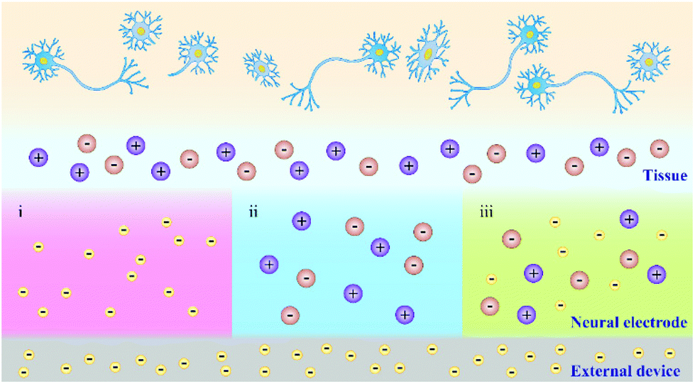
Due to the different charge transfer behaviour of neural electrodes and biological tissues/cells, where the charge transfer in the electrode materials mainly relays on electrons and the tissues/cells use ions to transfer charge, an effective and stable information transfer of the neural interface is important for the construction of neural electrodes (Fig. 1a).35,36 The optimization of mechanical interaction and understanding of the charge transfer mechanism between the electrode and tissues could favour the establishment of an effective neural interface, so as to promote the development of neural electrodes. Therefore, in the consequent part, we discussed the mechanical interaction between the electrode and tissue. Then, we further discussed the signal transmission mechanism in electrode materials, tissues and electrode–tissue interfaces.
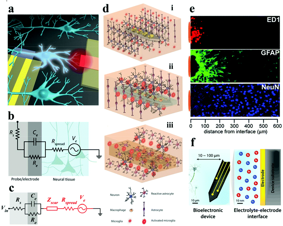 | ||
| Fig. 1 (a) Schematic of the gap between bioelectronic interfaces. Reproduced with permission from ref. 37. Copyright 2016, the American Chemical Society. (b) Illustration of the equivalent circuit between the electrode–tissue interface, (c) effect of the neuroinflammatory response (Zscar) on partial electrical impedance. Reproduced with permission from ref. 20. Copyright 2017, American Association for the Advancement of Science. (d) The process of glial encapsulation after electrode implantation: illustration of (i) implanted nerve electrode, and (ii) acute and (iii) chronic responses of the electrode. Adapted with permission from ref. 38. Copyright 2014, the Wiley-VCH. (e) The foreign body reaction in the brain tissue of animals implanted with microelectrodes for 4 weeks may be caused by the formation of inflammatory cells (ED1), astrocytes (GFAP) and the increased distance (NeuN) of neurons from the recording position. Reproduced with permission from ref. 39. Copyright 2005, the Elsevier. (f) Schematic description of signal conversion between the electrode and target cell interface in biological systems usually occurs at 10–100 μm. Reproduced with permission from ref. 21. Copyright 2019, the Royal Society of Chemistry. | ||
2.1. Mechanical interaction of the electrode–tissue interface
Favorable biomechanical interactions require the electrode to maintain splendid parameters (e.g., biocompatibility, stability, electrochemical performance, etc.). The biomechanical interactions of nerve electrodes are generally categorized into two types: one is the noninvasive electrode with epidermal attachment, and the other one is the invasive electrode with in vivo implantation. Epidermal electrodes universally trigger less invasive biomechanical interactions when in conformal contact with soft skin tissue (e.g., curving, stretching, compression, etc.).40 However, more complex biomechanical interactions (e.g., puncture wounds and destruction of the microvascular system) occur with invasive electrodes, especially the implantable nerve electrodes.21The electrode is taken as an example for recording the electroencephalogram (EEG). With the aggrandizement of time, the blood–brain barrier will be destroyed and blood vessels will be damaged, resulting in the death of a large number of nerve cells around the electrode (Fig. 1d).41 At this point, the immune system of the body is activated. Microglia and macrophage cells (derived from blood) are activated and release chemokines that attract astrocytes towards the electrode surface to aggregate (Fig. 1e). Astrocytes secrete some neurotoxic factors and the extracellular matrix, which lead to the death of neurons around the electrodes and the formation of dense glial scars, respectively.42 The glial scar will fortify the distance between the electrode and the target neuron, and at the same time, the impedance of the neural interface will increase dramatically. Equivalent circuit models can be employed to intuitively describe the impedance increase at the electrode–tissue interface (Fig. 1b and c). Higher interface impedance will seriously impede the acquisition of bioelectronic stimulation and recording signals (Fig. 1f).20,37,43,44 When the glial scar becomes too bushy and the neurons around the electrode die due to inflammation (acute and chronic),45,46 the electrode loses its function. So far, methods for perfecting the compatibility of bioelectrodes include: (i) surface coating;47 (ii) doping;48 (iii) covalent grafting;49 and (iv) layer-by-layer self-assembly technology based on electrostatic attraction.50
Besides the reasons described above that cause the increase of impedance, it is discovered that equipment/electrode degradation induced by operation in a biological environment also could result in an impedance increase. Therefore, improving the electrochemical performance and enhancing the biocompatibility of the neural electrode are the most important requirements for its practical applications. These requirements could be satisfied to a certain extent by the following strategies: (i) minimizing the gap of the neural interfaces;51 (ii) improving the interface adhesion between the electrode and the tissue;52 (iii) reducing the electrode thickness;40 and (iv) enabling the electrode with porous/3D structures.53
2.2. Signal transmission between the neural electrode and tissue
It is an important parameter to evaluate the electrode–tissue interface that whether the electrode can monitor the electrophysiological signals from the nervous system and accurately stimulate them.54 Hence, in this part, we would like to discuss the charge transferring mechanism in the neurons, electrode–tissue interface, and electrode materials, so that to provide theoretical support and design guidelines for the precise fabrication of neural electrodes. Notably, this article only focuses on the electrical interface directly formed between the electrode and the nerve tissue. The discussion of the chemical and optical modes of the neural interface could be found in previously reported reviews.5,55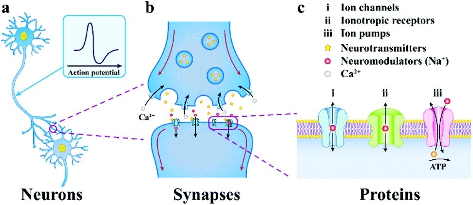 | ||
| Fig. 2 The progressively amplified communication diagram from a neuron to a synapse to an ion channel. (a) neurons communicate through chemical and electrical signals, (b) the presynaptic membrane releases neurotransmitters, which then spread via the synaptic cleft and integrate to receptor proteins on the postsynaptic membrane, (c) multiformity of neuronal membrane receptors included in neurotransmission. Reproduced with permission from ref. 5. Copyright 2019, Springer Nature. | ||
This neurotransmitter reaches the postsynaptic membrane (constituted by a dendritic membrane or cell body membrane) by chemical diffusion and binds to a specific receptor molecule on the membrane, causing the channel to be opened and Na+ to enter the postsynaptic cells. When the membrane potential threshold exceeds the unit's potential, the action potential is triggered, and the neuron signal is transmitted from the presynaptic membrane to the postsynaptic membrane, which makes another neuron excited or inhibited.58 Subsequently, the neurotransmitter is reabsorbed into the presynaptic cells, which completes the transmission of synaptic signals. In brief, the electrical communication between neuron cells mainly depends on the flow of ions.
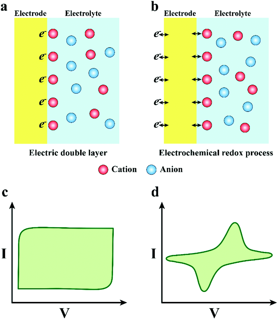 | ||
| Fig. 3 (a) Schematic drawing of the capacitive charge injection mechanism (electric double layer), (b) Faraday charge injection mechanism (electrochemical process), and (c and d) their corresponding cyclic response. | ||
In one way, the charge transfer depends on the charging and discharging process of the electric double-layer capacitor formed on the electrode surface (Fig. 3a and c). When the electrode transmits an electric pulse, the concentration of electrostatic charge on the surface will change, accompanied by alternate attraction and exclusion of the ions in the tissue fluid. There is no electron transfer between the electrode and the electrolyte during this process. More meaningfully, the electrode adsorbs a layer of polarized water molecules on the surface to act as a dielectric for the electric double layer capacitor.61 Notably, the capacitive charge transfer mechanism will not produce or consume chemicals, so it is more appropriate for the practical application of neural electrodes. Nevertheless, the capability of charge transfer of the electrode depends on the capacitance of the electric double layer capacitor, and the capacitance is positively related to the electrode area. However, normally, the electrode areas are too small to satisfy the requirement of high-density charge injection. Enlarging the surface area of the neural electrode will promote its development and application in the neural interface.
In the other way, the charge transfer relies on the electrochemical reaction on the electrode surface, which is a Faraday procedure (Fig. 3b and d). That is to say, when the electrode transmits an electrical impulse, the electrode–tissue interface will correspondingly undergo a redox reaction. The procedure is accompanied by the oxidation or reduction of chemical substances, which manifests as electrons pass through the electrode–tissue interface. The Faraday charge transfer process is divided into irreversible and reversible routes according to whether new substances are eventually generated. In the irreversible Faraday process, an irreversible oxidation–reduction reaction occurs, which will not only lead to electrode decay and variation of the pH value in tissue fluid, but also generate some harmful substances. Thus, it is better to avoid the charge transfer engaging through an irreversible Faraday pathway. In addition, for the reversible Faraday process, although the new material is formed on the electrode surface, when the opposite pulse current passes through the electrode, new substances will be absolutely reduced to the initial state. Therefore, the process does not import new materials to the tissue or bulk solution. Hence, the charge transfer via a reversible Faraday process is secure and feasible. It is vital that the corresponding redox reaction appears when the charge is injected in the Faraday reversible procedure, implying that the electrode interface can accommodate more charges. Consequently, the neural electrodes with a reversible Faraday charge injection process are preferred compared with the one with the irreversible Faraday process.
 | ||
| Fig. 4 Schematic diagram of the charge transfer mechanism of neural electrode materials: (i) charge transfer by electrons, (ii) charge transfer by ions, and (iii) charge transfer by the synergetic effect of electrons and ions. | ||
3. Current developing status of neural electrodes
Considering the complicacy and diversity of the neural interface, it is critical and challenging to select applicable materials to enable neural electrodes with high resolution, perfect electrochemical performance, excellent biocompatibility and long-term stability. In the following parts, we discuss the design schemes and performance evaluation of the reported neural electrodes in terms of their charge transfer mechanisms (Table S2†).3.1. Neural electrodes that transfer charge by electrons
Innovative breakthroughs have been made in materials, sizes, shapes and textures of nerve electrodes to optimize their electrical properties, biocompatibility and mechanical properties. The neural electrodes made from metals or carbon materials, employ free electrons as mobile charge carriers to communicate with biological tissues.25,62 Because of their outstanding electrical conductivity (106–107 S m−1),69 long-term longevity, etc.,63 they are broadly used in deep brain stimulators, cardiac pacemakers, retinas70 and so on. In this chapter, we chiefly review the design strategies of neural electrodes that transfer charge by electrons.3.1.1.1. Nanometal electrode. Owing to the pressing need for neural electrodes with a small size, large number of channels, and high electrode density, researchers have fabricated plentiful representative electrodes such as metal microwire electrodes (Fig. 5a).76 Nevertheless, this electrode still has faced inevitable shortcomings: (i) the metal microwire may be partly bent during the implanting process, generating it in an inconclusive position after implantation; (ii) this type of electrode has rigid characteristics, after implantation, it will cause glial activation to trigger tissue inflammation; and (iii) the electrode exhibits low charge injection capability and relatively high impedance, which lead to a decrease of performance in electrophysiological recording and stimulation. Advances in materials and micromachining technology have accelerated the development of another type of metal-based electrode (Fig. 5b),77 which is made of stainless steel/titanium. After the stainless steel electrode had been chemically etched to smooth the electrode surface, platinum was electro-deposited on its tip, which promotes the charge transfer at the electrode–tissue interface.78 The dominating disadvantage of these electrodes is their incompatibility with integrated circuit fabricating technology. As researchers continue to optimize the performance of neural electrodes, nanoporous metal electrodes have been developed. Both in vivo and in vitro studies have found that these electrodes had lower impedance and higher conductivity than their smooth counterparts. For example, a porous silicon electrode implanted in the brain of a rat was not only closer to neurons than smooth silicon, but also activated less glial.81In vitro porous platinum electrodes have lower impedance than smooth platinum electrodes.82 Moreover, Aifantis et al.83 implemented a nanoporous tungsten electrode for signal recording in the cerebral cortex and hippocampus of healthy rats. Compared with smooth electrodes, it was revealed that nanoporous tungsten had superior consistency and less signal attenuation within 4 months of implantation.
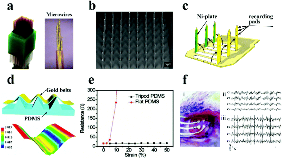 | ||
| Fig. 5 (a) Diagram of the microwire electrode. Reproduced with permission from ref. 76. Copyright 2014, Nature Publishing Group. (b) SEM image of the metal-based electrode. Reproduced with permission from ref. 77. Copyright 2004, IEEE. (c) Schematic illustration of the microprobe electrode array. Reproduced with permission from ref. 79. Copyright 2003, IOP publishing. (d) Schematic of the tripod PDMS bending structure and related strain distribution analysis using the finite element method, (e) the change of the electrode resistance under diverse deformations, (f) the image of the electrode array on the rat brain (i), and ECoG signals recorded in normal (ii) and epileptic (iii) rats. Reproduced with permission from ref. 80. Copyright 2015, Wiley-VCH. | ||
Recently, to further improve the electrode performances, flexible substrates (e.g., polydimethylsiloxane (PDMS), polyimide, polyurethane (PU), poly-p-xylene) have been introduced into the electrode, which represents the following advantages: (i) the electrode provides conformal adhesion to fit on the surface of brain/muscle to record stable signals and gain stimulation; (ii) flexible electrodes can record a diversity of neurological activities in a tenderly invasive manner with less injury; and (iii) the electrode can effectively decrease the impedance at the neural interface and reduce tissue injuries to further advance its electrical performance. As monitored in Fig. 5c, Fujita et al.79 successfully designed and manufactured a three-dimensional flexible multi-channel microprobe electrode array. This electrode was successful in monitoring neural activity in disparate depth regions of the brain using poly-p-xylene as the substrate material. The flexible electrode can be well fitted on the brain surface and can shake synchronously with the weak movement of the brain, which supplies a powerful safeguard to avoid tissue harm during brain micro-movement. Afterwards, Qi et al. designed a high tensile gold nanoribbon flexible electrode with a sinusoidal structure using a micro-tripod structured PDMS substrate (Fig. 5d).84 The resistance of the electrode did not increase under large deformation (130% strain) (Fig. 5e), and the electrodes maintained stable conductivity during 10![[thin space (1/6-em)]](https://www.rsc.org/images/entities/char_2009.gif) 000 cycles of the stretching/relaxing process, which is enough to avoid the distortion of the signal in the process of dynamic electrophysiological recording. The as-prepared electrodes were successful in recording and distinguishing the cortical electroencephalogram (ECoG) in normal rats and epileptic rats (Fig. 5f).
000 cycles of the stretching/relaxing process, which is enough to avoid the distortion of the signal in the process of dynamic electrophysiological recording. The as-prepared electrodes were successful in recording and distinguishing the cortical electroencephalogram (ECoG) in normal rats and epileptic rats (Fig. 5f).
3.1.1.2. Composite metal electrode. The traditional metal electrodes have adverse effects to overcome for electrophysiological monitoring and tissue stimulation, such as high impedance and poor biocompatibility. Consequently, metal composite materials are proposed to improve the long-term performance of metal based neural electrodes. According to the design point of view, the generation of parasitic effects should be evaded, so the combination of similar materials is more preferred. Normally, metal materials and their derivatives (iridium oxide, gold, platinum) are selected as materials for the fabrication of composite metal electrodes.
As discussed previously, a large surface area of the electrode can reduce its impedance and enhance its charge injection capability. For metal electrodes, nano-structured materials with high porosity were used to improve the effective surface area of the neural electrode, thereby facilitating its electrochemical performance. Presently, gold (Au) is considered to be a hopeful material, which is normally employed for electrode coating of metals by electrochemical deposition, sputtering, thermal evaporation and so on. Kim et al. fabricated a multi-electrode array (60 channels) by coating gold nanoparticles (AuNPs) on the electrode using a bi-layer lift-off resist and sputtering deposition (SiO2) process.85 They disclosed that the impedance of the modified electrode was reduced by four times compared with the original electrode. Subsequently, the researchers found that using nano-structured templates to prepare metal coatings is an excellent method to enlarge the effective surface area and reduce impedance.86,87 Additionally, the good biocompatibility of AuNP coated electrodes has also been proven.88,89 Encouragingly, the electrode obtained by co-deposition of Ag–Au alloy has higher porosity, whose impedance was approximately 25 times lower than that of the pristine electrode, and the CSC and CIL of the electrode were equivalent to the values of an electrode made of titanium nitrous and carbon nanotubes, respectively.88–90
To overcome the rigid and brittle features of metal electrodes, Choi et al.91 innovatively employed a gold shell layer to coat silver nanowires, and then combined it with a rubber elastomer (poly (styrene–butadiene–styrene)) to fabricate stretchable neural electrodes, and the as-prepared soft and highly stretchable Ag–Au core–sheath nanocomposite material achieved remarkable electrical conductivity (41850 S cm−1). The biocompatibility of the electrode in cell culture medium, human cells and mouse organs was much better than that of silver fibers (Fig. 6a), which is attributed to the deposition of a thick gold sheath on the surface of silver nanowires to prevent silver oxidation and ion leaching. The Ag–Au nanocomposite electrode not only minimizes the gap between the electrode and the skin, but also has a lower impedance (Fig. 6d), resulting in high-quality electrocardiogram (ECG) and electromyogram (EMG) signal monitoring (Fig. 6b and c). In this study, the gold core–shell structure was implemented to protect the silver fiber, which cleverly solved the incompatibility between the silver fiber and the biological environment. It provides a solution for similar problems in other related research territories.
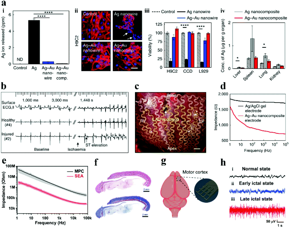 | ||
| Fig. 6 (a) The biocompatibility of Ag–Au nanocomposite electrodes and silver fibers: the concentration of silver ions in the cell culture medium (i), the effects of different cell viability (ii and iii) and various organs in mice (iv), (b) electrode-recorded surface ECG and intracardiac electrograms of the ischemic heart in the healthy and injured areas, (c) photo of a cardiac mesh implanted on a pig heart, (d) the impedance of diverse electrodes at the electrode–skin interface. Reproduced with permission from ref. 91. Copyright 2018, Nature Publishing Group. (e) Impedance diagram of the electrode, (f) Hematoxylin & eosin and Masson staining results of the tissue surrounding the implanted SEA, (g) schematic of the recording of the SEA in vivo, (h) ECoG signals recorded by the SEA: (i) healthy, (ii) early and (iii) late epileptic rats. Reproduced with permission from ref. 92. Copyright 2021, Wiley-VCH. | ||
Compared with the toxic silver nanowires,93,94 liquid metal (LM) has good biocompatibility, excellent electrical conductivity and mechanical flexibility. Therefore, the liquid metal is constantly applied in the preparation of neural electrodes to conquer the challenges and deficiencies of traditional electrodes (e.g., microwire electrodes, silicon-based electrodes, metal-based electrodes).95,96 For example, Liu and his collaborators employed bismuth–indium–tin (Bi–In–Sn) liquid alloy materials to fabricate 3D microneedle electrodes via a micro-injection molding method.97 After evaluating the electrical impedance and polarization voltage of the electrode, it is believed that the electrodes can meet the demands of practical applications. In addition, the electrode made from EGaIn (eutectic gallium indium) LM can not only be used in vitro to detect ECG physiological signals,98,99 but also be implanted in vivo for neural activity monitoring. Recently, Dong et al. applied the screen printing technology to fabricate a stretchable electrode array (SEA) with EGaIn LM as the conductor and PDMS as the substrate, with a resolution of ∼50 μm.92 The impedance of the electrode with Pt deposition is about 250 ± 40 kΩ at a frequency of 1 kHz in phosphate buffer solution (PBS), which is much lower than that of the liquid metal electrode (2.7 MΩ ± 150 kΩ) (Fig. 6e). What is more noteworthy is that one month after the SEA was implanted in the back of rats, the surrounding tissues had been almost unaffected (Fig. 6f), implying that the SEA has benign biocompatibility. The SEA was also implanted in the brain of rats and successfully monitored the real-time data of the rats in disparate states of epileptic seizures (Fig. 6g). The high-quality data (Fig. 6h) demonstrate that the electrodes formed conformal contact with the brain surface and the electrodes were competent for recording high-throughput ECoG signals. In parallel, the LM gallium indium tin (GaInSn) alloy has been considered as a promising material for restoring nerve function.95,100,101 Currently, the thorny problems of LM in practical applications are as follows: (i) overcome the surface tension of LM, making it an ideal shape for neural electrodes; (ii) destroy the oxide layer of the LM particles inside the ink, so that the prepared electrode path can be connected; (iii) the embrittlement of the connection point between the LM and traditional conductive metal materials (e.g., copper, gold, zinc) should be reduced, which can effectively improve the stability of the neural electrode; and (iv) the encapsulation of the LM electrode, which can increase the stability and solve the problem of leakage.
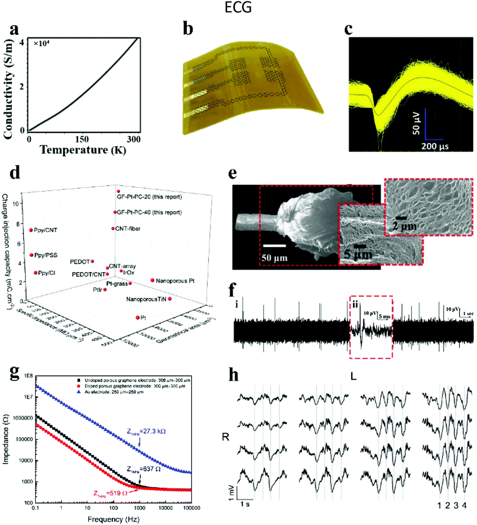
3.1.2.1. Graphene electrode. Graphene is a single-layer two-dimensional honeycomb lattice structure material formed by densely packed carbon atoms connected by sp2 hybridization. Recently, graphene has been seen as an executable material in the territory of neural interfaces. Its preeminent features include the following: (i) it is one of the highest-strength materials known, while still having good flexibility; (ii) it possesses attractive electronic conductivity (thin layer resistance: 100 Ω sq−1) with a carrier mobility of 15
000 cm2 V−1 s−1 at room temperature (Fig. 7a);25,102 (iii) it has a large specific surface area, which supplies a favorable environment for charge transfer and cell attachment, thereby enhancing the efficiency of stimulation and the sensitivity of recording; and (iv) it exhibits fascinating biocompatibility, which is ascribed to the functional groups modified on the graphene surface, making them more suitable for research in the field of biomaterials (Fig. 7b). Furthermore, graphene can be functionalized to produce graphene oxide, reduced graphene oxide and chemically modified derivatives, which provide more choices for its application as biological neural electrodes.103–106 Hence, the preparation of flexible graphene microelectrodes is helpful to realize the tissue stimulation and neural activity recording, owing to the high electrochemical performance of graphene.107 For example, Yao et al.108 prepared a flexible graphene microelectrode and treated it with the vapor plasma technology to form hydrophilic chemical bonds (e.g., C–OH, C![[double bond, length as m-dash]](https://www.rsc.org/images/entities/char_e001.gif) O, OH–CO) on the surface. This treatment promoted the decline of the interfacial resistance from 7216 to 5424 Ω mm−2 and the reinforcement of the specific capacitance from 0.7 × 10⁻³ to 1.4 × 10⁻³ mF cm−2, respectively. The electrode has been successfully used for ECG monitoring in zebrafish.
O, OH–CO) on the surface. This treatment promoted the decline of the interfacial resistance from 7216 to 5424 Ω mm−2 and the reinforcement of the specific capacitance from 0.7 × 10⁻³ to 1.4 × 10⁻³ mF cm−2, respectively. The electrode has been successfully used for ECG monitoring in zebrafish.
 | ||
| Fig. 7 (a) Conductivity of graphene fibers at diverse temperatures. Reproduced with permission from ref. 25. Copyright 2020, Elsevier. (b) Diagram of graphene neural electrode arrays. Reproduced with permission from ref. 109. Copyright 2014, Nature Publishing Group. (c) 1543 single unit signals acquired by implanted electrodes, and the black wire in the center of the waveform expressing the average value of single unit signals, (d) plot of CIC, specific impedance, and geometric area compared with other neural electrodes. Reproduced with permission from ref. 110. Copyright 2019, Wiley-VCH. (e) Surface roughness and porosity generated after laser treatment of fiber ends, (f) neural activity recorded within 20 seconds of implantation into the visual cortex of cats. Reproduced with permission from ref. 111. Copyright 2015, Wiley-VCH. (g) Comparison chart of the electrochemical impedance of different materials, (h) spontaneous upward and downward state signals recorded by 16 electrode arrays. Reproduced with permission from ref. 112. Copyright 2016, Springer Nature. | ||
The impedance of graphene fiber based neural electrodes could be dramatically reduced by coating Pt on the electrode surface.110 After Pt coating, the impedance of this electrode was reduced by 5 times compared with the bare graphene electrode, and 300 times lower than that of the bare Pt electrode. Simultaneously, the charge injection capacity (CIC) of the electrode was increased from 0.2 mC cm−2 to 10.34 mC cm−2 (Fig. 7d). This is due to the good porous structure of graphene fibers prepared by the wet spinning method, which increases the surface area of the composite material. At the same time, the electrode successfully recorded the signal of a single neuron's activity at a depth of 1.5 mm below the motor cortex of rats (Fig. 7c), indicating the advantages of the electrode for in vivo neural recording. Accordingly, Garrett and his collaborators also gained graphene oxide fibers by wet spinning, and successfully made liquid crystal graphene oxide fibers by annealing.111 Afterwards, the fiber end was disposed with a laser to render the surface roughness and poriness (Fig. 7e), and finally a neural electrode with high charge injection capability was fabricated. After implanting the electrode on the cat's visual cortex, the action potential of neural activity was successfully recorded (Fig. 7f). Otherwise, graphene can be used not only as a conductive layer, but also as a coating layer on neural electrodes to enhance the biocompatibility and electrochemical performance of the traditional neural electrodes.113,114 The graphene coating layer can be pre-grown on the substrate by a spraying method115 or a chemical vapor deposition (CVD) strategy116 and then transferred to the target electrode. However, a challenge is that the stability between the coating graphene and the substrate is poor, leading to the degradation of the electrode performance. To address this challenge, Lyu's group employed laser cracking techniques to fabricate a porous graphene electrode array directly on a polyimide substrate.112 The impedance of this electrode was about two orders of magnitude smaller than that of gold at the same size, which was due to the seamless contact between the substrate and the three-dimensional porous graphene. After the electrode was chemically doped with nitric acid, the impedance reduced to 519 Ω at 1 kHz (Fig. 7g) and the CIC increased from 2 mC cm−2 to 3.1 mC cm−2. Furthermore, by placing the electrode array on the cortex of a rat, the evoked potential signals were successfully recorded (Fig. 7h). Simultaneously, the electrode was also successful in inducing the flexion of the ankle and knee joints by applying electrical stimulation.
3.1.2.2. Carbon nanotube electrode. CNTs can be regarded as one-dimensional nanomaterials formed by curling graphene sheets with the following advantages for use in neural electrodes: (i) it has high conductivity, which facilitates the transfer of electrons from the interface to the electrode body; (ii) the material has a high surface area to volume ratio, which can promote the increase of the electrode charge injection ability and the decrease of the interface impedance;117,118 and (iii) the functional groups contained on the surface of CNTs are easy to be modified by biomolecules, which enables the neural electrode to be adjusted in multiple directions according to the needs of practical applications.119,120 Moreover, it also has perfect biocompatibility, flexibility, high mechanical strength, and captivating nerve cell adhesion.121–123 Based on these ideal characteristics, CNTs have received more and more attraction in the orientation of neural electrodes (Fig. 8a).124–126
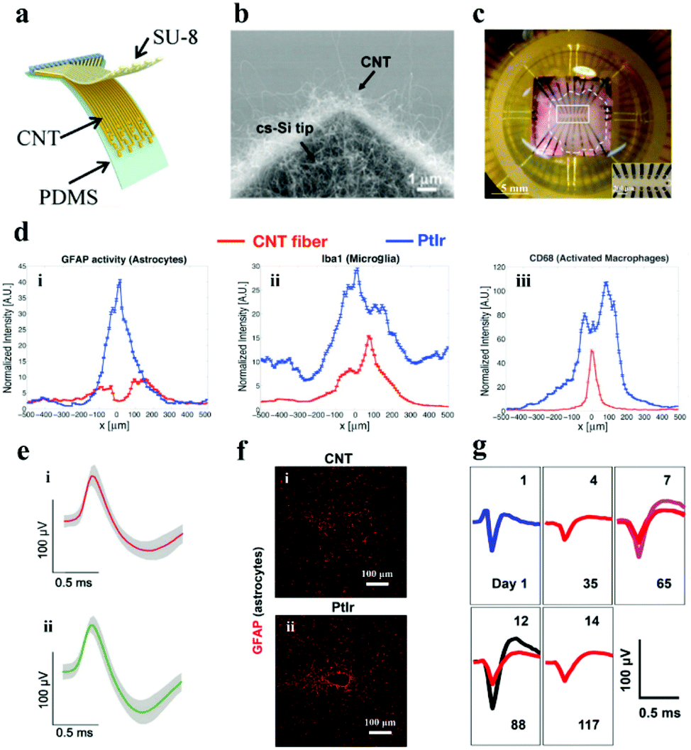 | ||
| Fig. 8 (a) Illustration of the flexible CNT electrode array. Reproduced with permission from ref. 128. Copyright 2018, American Chemical Society. (b) SEM image demonstrating the cone-shaped silicon tip of the CNT electrode. Reproduced with permission from ref. 127. Copyright 2010, Elsevier. (c) CNT electrode array mounted on the printed circuit board holder connects the electrodes to the exterior magnifier. Reproduced with permission from ref. 129. Copyright 2014, Springer. (d) Fluorescence intensity distribution when the lateral distance x of the electrode center line augments: (i) astrocytes, (ii) microglia and (iii) activated macrophages, (e) single neuron action potential data recorded on the (i) CNT fiber and (ii) NiCr-Au channel. Reproduced with permission from ref. 130. Copyright 2015, American Chemical Society. (f) Contrast of tissue inflammation between the CNT fiber and platinum iridium (PtIr) electrode, (g) average waveforms of individual neurons at detection and separation were recorded from day 1 to day 117. Reproduced with permission from ref. 131. Copyright 2019, American Chemical Society. | ||
There is a trade-off between the impedance and the size of the neural electrodes. Reducing the size of the neural electrode always results in the increase of its impedance, however, the electrode with a small size and low impedance is highly desired for neural activity recording with high resolutions. To balance this trade-off, Yew et al.127 demonstrated a rewarding strategy for low impedance neural electrodes with a miniature size (3.5–65 μm in diameter) by employing CNTs as the electrode material. Firstly, CNTs were grown on cone-shaped silicon by a CVD method (Fig. 8b), the cone-shaped silicon presents a larger surface area than the flat silicon, and the surface area was further enlarged by the deposited CNT. Therefore, the impedance (∼64.5 Ω mm−2) of the electrode was observably descended and the specific capacitance (∼2.5 mF cm−2) was increased. The electrode has desired spatial resolution and splendid electrochemical performance for crayfish monitoring. The electrochemical properties of the electrode have been further improved with the consecutive investigation of the researchers,132–134 but the flexibility has always been an emergency need for the practical application of neural electrodes.135 Hanein and colleagues directly transferred the multi-walled CNT pattern grown by CVD to a flexible polymer substrate to fabricate a flexible full CNT electrode array.129 After repeated folding and winding for 30 cycles, the resistivity of the electrode did not change too much. Moreover, the electrode was successful in extracellular neuron recording and the stimulation of the chicken retina (Fig. 8c). It manifests that the electrochemical performance and flexibility of neural electrodes with the assistance of CNTs can be signally strengthened. Moreover, CNTs also play an important role in improving the biocompatibility of the neural electrode. The CNT fiber electrode manufactured by Pasquali's team showed a lower impedance, and higher CSC (372 ± 56 mC cm−2) and CIL (6.52 mC cm−2) compared with the PtIr based line-shaped electrode.130 More importantly, the number of activated microglia and accumulated astrocytes at the CNT fiber electrode was twice and four times lower than that at the PtIr electrode after they were embedded in rats for 6 weeks (Fig. 8d). TheCNT fiber electrode was successful in recording single neuron action potentials for at least 21 days after being implanted into the primary motor cortex of cats (Fig. 8e). It demonstrates that the CNT fiber electrode has better biocompatibility and stability. In addition, Duan et al. have made microelectrodes with small-diameter carbon nanotube fibers, which constituted a double electric layer at the electrode–solution interface to control the electrochemical process.131 It delivered better CIL and CSC properties compared with the PtIr electrode. In addition, the CNT fiber microelectrodes have more stable and gainful microenvironmental ability in the neural interface when compared with the metal rigid electrode. Furthermore, the researchers implemented an innovative shuttle-assisted means to precisely position the CNT fiber electrode to the target brain region and recorded individual neurons for up to 4 months (Fig. 8g). Meaningfully, the electrode can be retracted controllably after insertion owing to its good tensile strength.
In addition to serving as a conductive layer, CNTs can also act as a modification material to improve the electrical activity of the neural electrode.134,136 For instance, the impedance of the commercial tungsten neural electrode could be reduced (from 940 kΩ to 38 kΩ) after modifying CNTs on its surface, at the same time, the CSC of the electrode has enhanced approximately 40 times.137 Moreover, the amplitude of the electrophysiological signal recorded by this electrode was larger and its noise was lower compared with that recorded by the unmodified electrode. Additionally, Vafaiee and his collaborators prepared a gold multi-electrode array coated with CNTs, and the impedance after CNT modification was reduced by 50%.121 Not only that, the CNT coated electrode also was able to monitor the electrophysiological activity in vitro.138
3.2. Neural electrodes that transfer charge by ions
Signal transmission in human biological systems is dominated by the transfer of ions and small molecules, rather than electrons and holes in electronic devices.139,140 When ions act as charge carriers in water-rich biological tissues, the tissues have much higher electrical conductivity than using electrons and holes as the charge carriers.141,142 Consequently, ionically conductive bioelectronic devices have been paid more and more attention by scientific researchers.143–145 Currently, the application of liquid-type ionic conductors (e.g., electrolyte solutions and ionic liquids) is restrained due to the need for molds to maintain their shape.146 In contrast, solid ionic conductors have attracted much more attention.147,148 Recently, owing to the inherent remarkable biocompatibility, flexibility, biological activity, and compliance with nerve tissue, hydrogels have been widely used in the biological investigation including cell culture,149–151 drug delivery,152–155 tissue repair,156–158 reconstruction, etc.159–161 Simultaneously, hydrogels have also been employed in the manufacture of functional devices, such as sensors,163–165 optics,165–167 bioelectronics and so on. Importantly, as candidate materials for flexible bioelectronics, hydrogels have become a momentous part of neural electrodes.168–170To our delight, three dominating hydrogels have been explored to be engaged in the electrode–tissue interface: (i) ion conductive hydrogels; (ii) ion conductive organohydrogels; and (iii) composite hydrogel materials. In the following part, the advantages of hydrogels in boosting the electrical activity of neural interfaces are discussed, which will furnish valuable reference strategies for the electrochemical properties and long-term stability of neural interfaces during the process of electrophysiological signal recording and neural stimulation. Here, we focus on hydrogels with ionic conductivity for neural electrodes. The hydrogels whose conductivity is contributed by the synergistic effect of the electrons and ions will be discussed in 3.3.4.
However, ICHs prepared by incorporating salts have low stability and poor biocompatibility due to the diffusion of added ions, which are not suitable for bioelectronic devices. To solve this problem, Kaplan et al. developed a programmable ICH containing phase separation salt/polyethylene glycol (PEG) (Fig. 9a and b).162 The advantage of this electrode is to ensure that the ionic aqueous solution will not be diffused into the surrounding tissue media. Experiments show that the ICH ion electrode can produce complete twitch forces at a smaller stimulation voltage compared with the traditional metal electrode, indicating that the ICH ion electrode shows good performance for bioelectrical stimulation (Fig. 9c). As illustrated in Fig. 9d–f,† the ICH ion conductor is relatively stable in a physiological environment, indicating that the electrode can satisfy the long-term electrical stimulation of muscles in the body. Additionally, it has been reported186 that implanted neural electrodes coated with polyethylene glycol dimethacrylate (PEG-DMA) hydrogels have preeminent biocompatibility and can effectively decrease the injury of nerve cells around the electrodes. Nevertheless, in monitoring, unnecessary gaps are generated at the electrode–tissue interface due to muscle contraction or skin bending (surface electromyography abbreviation sEMG), which leads to serious noise/error in the detected signals, especially the signal from low-level muscle contraction. These gaps could be eliminated by introducing electrostatic interactions between the electrode and tissues. For example, Chen and his collaborators reported a compliant electrode based on alginate-polyacrylamide (Alg-PAAm) (Fig. 10a).51 The electrode eliminated interfacial gaps by forming extensive hydrogen bonds on the skin surface (Fig. 10b and c). As a result, a low interfacial impedance (about 20 kΩ at 1 Hz versus approximately 500 kΩ of the commercial electrode) was achieved (Fig. 10d) and 2.1% of the maximum autonomic contraction of the muscle was successfully monitored.
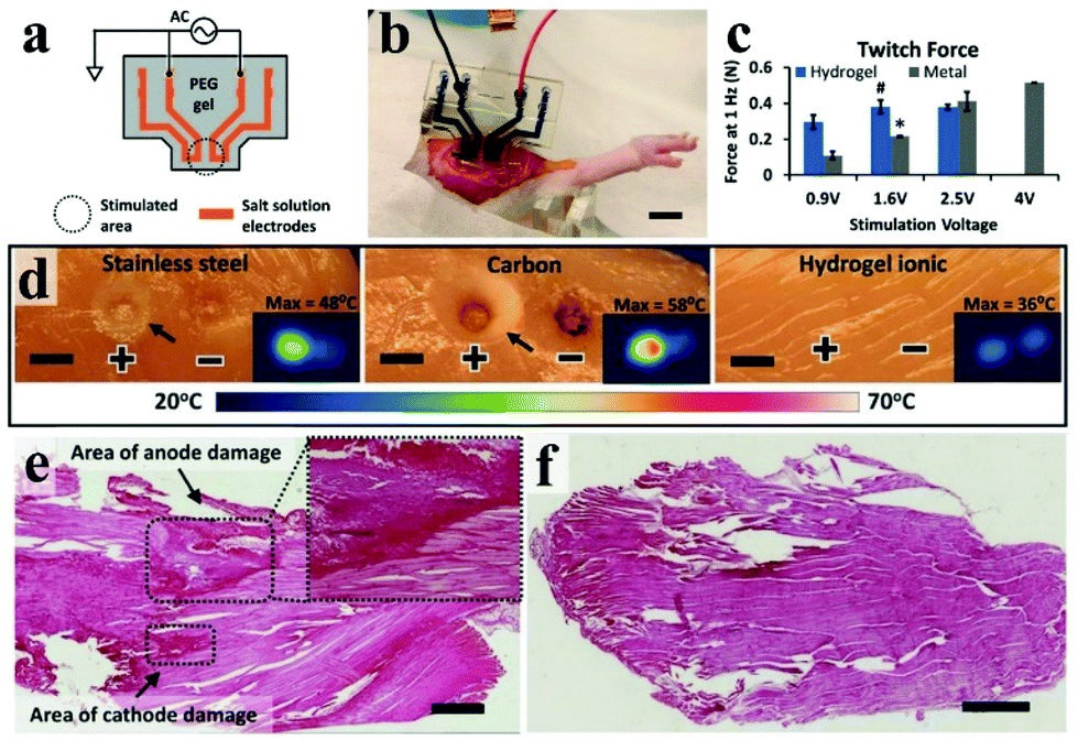 | ||
| Fig. 9 (a) Schematic diagram of an ionic stimulator electrode with ionic liquid encapsulated in a hydrogel, (b) photo of a salt/PEG hydrogel stimulated electrode in rat muscle, and scale bars are 1 cm, (c) the image of stimulating muscles to induce twitches using a 1 Hz pulse signal under the contrast conditions of standard gold electrodes, (d) using stainless steel, carbon and Alg-PAAm electrodes for current injection, the results reveal that Alg-PAAm electrodes can effectively lower local heating caused by current injection, and indirectly protect tissue damage, scale bars are 5 mm, (e) during the injection of high current, the gold electrode caused damage to the muscle tissue and (f) the Alg-PAAm ion electrode did not cause muscle injury, scale bars are 1 mm. Reproduced with permission from ref. 162. Copyright 2018, Wiley-VCH. | ||
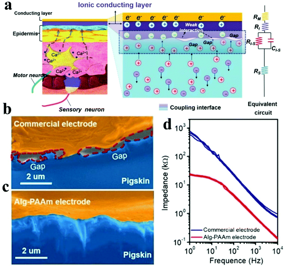 | ||
| Fig. 10 (a) Schematic of the electrode and skin used for EMG detection: describes the coupling process between ion flux (electrolyzed tissue medium) and current (electrode); SEM pictures display the interfacial clearance between pigskin and (b) commercial electrode or (c) Alg-PAAm electrode, respectively, (d) the impedance diagram of the electrode–skin system from 1–104 Hz. Reproduced with permission from ref. 51. Copyright 2020, Wiley-VCH. | ||
Although ICHs have been widely used in bioelectronics, ICH based electrodes tend to lose flexibility, conductivity and even change their morphology due to the characteristics of rapid dehydration, which severely inhibits their practical applications.187 At present, the solutions to this problem include adding dehydrating reagents,188,189 mingling polymer-ionic liquid gels,190,191 attaching sealing materials,192 and blending deep eutectic solvents (DESs) Recently, Guo and his team synthesized a transparent anti-drying PAAC-DES gel by polymerising monomer acrylic acid (PAAc) in a DES through ultraviolet radiation.193 The as-prepared gel showed high adhesion (∼100 N m−1) and desirable electrical conductivity (1.26 mS cm−1). In addition, the PAAc-DES gel not merely exhibits captivating compatibility to the skin after 8 hours of wearing, but also has low impedance and records high-quality sEMG signals compared with the commercial electrodes (Ag–AgCl electrode).
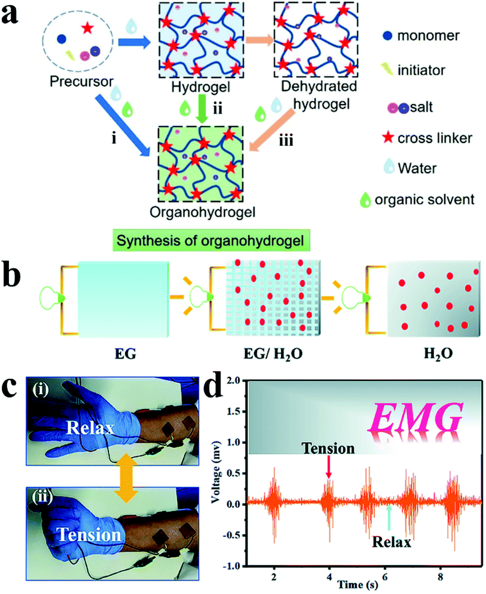 | ||
| Fig. 11 (a) Three synthetic methods of organohydrogels: (i) gelation in binary solvents, (ii) organic solvent replacement and (iii) organohydrogels polymerizing in situ on dehydrated hydrogels. Reproduced with permission from ref. 194. Copyright 2021, American Chemical Society. (b) Schematic illustration of ion conduction in multiple solvents, (c) monitor EMG signals under skin (i) relaxation and (ii) tension, (d) PVA-TA@talc organohydrogel detected EMG signal data. Reproduced with permission from ref. 203. Copyright 2019, the Royal Society of Chemistry. | ||
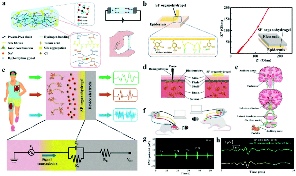
Low electrochemical impedance and high tissue adhesion are the requirements of ion-conducting materials for their application in bioelectrodes for neural interfacing. Hou et al. employed the hydrogen bonds between the chain of silk fibroin (SF) and poly (acrylamide-co-acrylic acid) covalent network to make SF uniformly dispersed to the hydrogel.205 Sodium chloride was added to form salting-out and accelerate molecular chain entanglement of hydrogels to increase ionic conductivity (Fig. 12a). As a result, a low impedance (27.8 Ω) was achieved with the SF organohydrogel. In addition, the free catechol/pyrogallol groups of tannic acid permit the formation of hydrogen bonds at the interface between the SF organohydrogel and the substrate, which enhanced the adhesion between the SF organohydrogel and the epithelial tissue (Fig. 12b). Hence, this electrode is a robust neural interface tool for monitoring ECG, microvolt EEG (Fig. 12c) and EMG signals (Fig. 12g). Incredibly, the electrode can be engaged for the auditory brainstem response (ABR) (Fig. 12d–f) and can obtain the same ABR detection signal waveform as the invasive metal electrode (Fig. 12h), which is of great significance for the diagnosis and treatment of patients with hearing impairment. In the long term, ICOHs are still in their infancy as an implantable nerve electrode, and the practical application of this type of electrode needs to be improved.
 | ||
| Fig. 12 (a) Schematic diagram of the chemical structure of the SF organohydrogel, and the illustrations show the ionic conductivity and self-adhesive properties of the electrodes, respectively, (b) the electrode conglutination principle and low electrode–epidermis interface impedance, (c) ECG, EMG and EEG signals detected by the SF organohydrogel electrode, and the following figure shows the equivalent circuit of the tissue/hydrogel electrode/device electrode interface for bioelectronic detection, (d) schematic of the SF organohydrogel interface and invasive electrode in the way of acquiring signals, (e) schematic description of the generated and transmitted ABR signals, (f) schematic of the SF organohydrogel interface and metal electrode measuring ABR signals, (g) the EMG signal of the SF organohydrogel on the forearm under diversiform clamping forces, (h) ABR signals collected by the SF organohydrogel electrode and invasive metal electrode under 90 dB stimulation conditions. Reproduced with permission from ref. 205. Copyright 2022, Elsevier. | ||
3.3. Neural electrodes that transfer charge by the synergetic effect of electrons and ions
Although the materials using electrons (metals, semiconductors) or ions (hydrogels, organohydrogels) as the charge carrier have been explored for the construction of neural electrodes, the ideal candidate materials should satisfy the requirements for effective charge transfer between the external device (electrons as the charge carrier) and the tissue (ions as the charge carrier). Therefore, the materials with an electron–ion synergistic effect for charge transfer are more suitable for the actual development of nerve electrodes. Recently, conducting polymers have been widely used in neural electrodes because of their unique ion–electron synergistic charge transfer behavior. Moreover, composite materials have attracted much attention because they can integrate the advantages of each component and conquer the disadvantages of a single material.124,206,207Conductive polymers (CPs) are frequently used in the research and development of neural electrodes due to the following characteristics: (i) CPs exhibit synergistic ionic and electronic conductivity,208 and this characteristic can be used to reduce the electrochemical impedance of neural electrodes; (ii) their inherent adjustable mechanical properties render them more applicable for acting as bridge materials of the electrode–tissue interface; (iii) CPs have porous structures (nanoparticles or nanofibers), which can reinforce the specific surface area of the neural electrodes, thereby facilitating ion exchange between the recording site and the circumambient tissues; and (iv) the material is effortless to combine with polyelectrolytes (e.g., polyacrylic acid, polymethacrylic acid, polystyrene sulfonic acid) and bioactive molecules,209 which further improves the biocompatibility of the material.210
Thus, in this section, the neural electrodes based on intrinsic conductive polymers (e.g., poly(3,4-ethylene-dioxythiophene) (PEDOT), polypyrrole (PPy), polyaniline (PANI) and so on) are discussed in detail (Fig. S1† for the conductive mechanism).67,68 Then, we review the magnificent mission of integrating two or more electroactive conductive materials (examples include hydrogel composite and CP composite materials) to achieve the signal transmission at the interface between nerve electrodes and biological tissues. We hope that it could provide a reference solution for the manufacture of neural electrodes with excellent performance.
000 stretching/relaxation cycles, indicating that it had favourable stability (Fig. 13a). In addition, the thin compliant polymer electrode not merely supplied outstanding conformality at the electrode–tissue interface, but also had a lower impedance and higher CSC compared with gold electrodes under identical conditions (Fig. 13b and c). Under the premise of satisfying the mechanical and electrochemical properties, the electrode was successful in distinguishing the ECoG signal from normal and epileptic state rats (Fig. 13d and e), which is crucial for the clinical application of polymer bioelectronics.
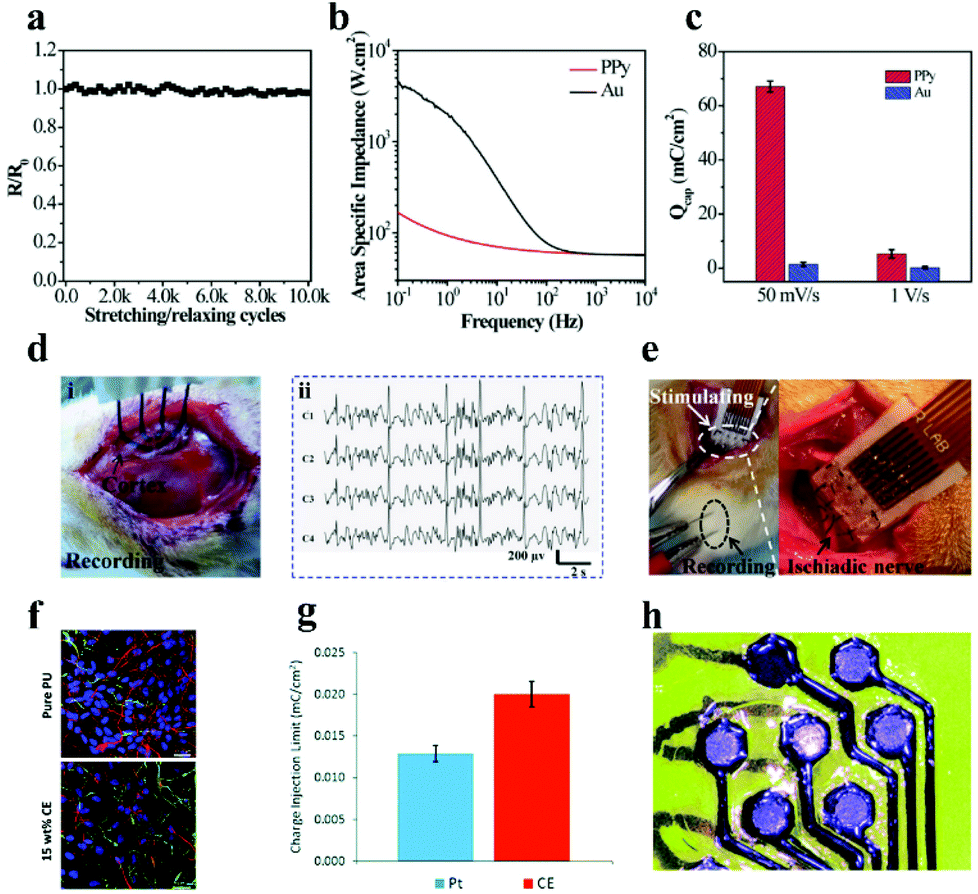 | ||
| Fig. 13 (a) Resistance changes of the microelectrode array after diverse stretching/relaxation cycles, (b) electrical impedance spectra of PPy membrane and Au membrane electrodes in phosphate buffer solution with pH = 6.8, (c) CSC of the PPy electrode and Au electrode, (d) monitoring photos (i) and ECG signal (ii) of the PPy electrode application test on epileptic rats, (e) electrode array-stimulated rat sciatic nerves (left) and magnified images (right). Reproduced with permission from ref. 215. Copyright 2017, Wiley-VCH. (f) Fluorescence image of the compatibility of pure PU and optimized 15 wt% CE electrode materials on human neural precursor cells after 7 days of culture, scale bar = 23.07 μm, the red, green and blue in the picture represent neurons, astrocytes and nuclei, respectively, (g) CIL comparison data of the CE electrode array and Pt electrode, (h) CE organic flexible electrode array after laser ablation. Reproduced with permission from ref. 216. Copyright 2019, the Royal Society of Chemistry. | ||
Additionally, carbon nanotubes (CNTs) have good mechanical strength and high conductivity (see section 3.1.2 for details). The combination of CPs with CNTs could enhance the conductivity of CPs and enlarge their surface areas. Hence, this CP/CNT composite material is a good candidate for modifying the metal bioelectrode. Thakor's group proposed a tunnel-like electrode coating layer made of PEDOT-CNTs for highly sensitive neural activity recording.233 Compared with the bare gold electrode, the impedance of the modified gold electrode was reduced by 50-fold, and an increase (65-fold) of the CSC about the modified electrode was achieved. This may be due to the following reasons: (i) during the deposition process, CNTs act as a dopant, resulting in a strong interaction between PEDOT and CNTs (the adhesion of the PEDOT coating is increased by about 1.5 times), which promotes the rapid transmission of electrons within the composite material; and (ii) the formation of three-dimensional structure and the increase of the geometric area (approximately 1.8 times more than non-nano tunnel structures). In parallel, a similar result was also achieved by Saunier et al.206 They uncovered that the electrodeposition of a composite material (PEDOT and carbon nanofibers) on a gold microelectrode array could reduce the electrical impedance and enhance the charge storage capability of the electrode.
CPs are widely used to construct composite materials with hydrogels for bioelectronics, owing to the following superiorities of CPs: (i) CPs have good flexibility and compatibility which benefits their hybridization with other polymer (hydrogel) systems; (ii) the unique organic and polymeric properties of CPs make them easy to be modified; and (iii) some CPs (e.g., PEDOT) present a hydrogel form in humid environments, which are attributed to their hygroscopicity or swelling properties when exposed to water.21 For example, a soft conductive hydrogel with high electrical activity was synthesized using PPy and alginate.237 Its electrical conductivity increased by more than ten times compared with the original hydrogel without PPy. Moreover, the hydrogel compounded with PPy has good biocompatibility as it can be implanted in the mice for eight weeks without an obvious rejection reaction of the tissues. In addition, PEDOT was also successful upon compounding with hydrogels and enhancing its conductivity. For instance, a conductive hydrogel with adjustable electrical and physical (swelling, mechanical) properties was synthesized by employing PEDOT:PSS and bio-derived polymers (gelatin methacryloyl).238 In particular, the impedance of hydrogels decreased from 449.0 kΩ to 281.2 and 261.0 kΩ after compounding 0.1% (w/v) and 0.3% (w/v) PEDOT:PSS at 1 Hz frequency, respectively.
Another way to enhance the conductivity of hydrogels is to compound electron conductive nanomaterials (e.g., metal nanowires, LM, CNT, graphene, etc.) with hydrogels. The charge transfer in the resulting materials was contributed by both the ions and electrons,148,175 which facilitates their application in bioelectrodes for neural interfacing. Inspired by the cytoadhesion structure, Cai et al. successfully prepared a locally coupled electromechanical interface based on a four-layer ionotronic hybridization (called CoupOn).231 The CoupOn is a combination of bimetallic nanofilm (Au/Ti) deposited PDMS and hydrogel (alginate/polyacrylamide) (Fig. 14a). Fig. 14b shows that CoupOn has a lower impedance than commercial electrodes (i.e., Vitrode F150ML) in the entire frequency range, which furnishes a beneficial guarantee for sEMG signal monitoring (Fig. 14c). This strategy supplies a new scheme for the conversion of electron and ion signals at the electrode–tissue interface.
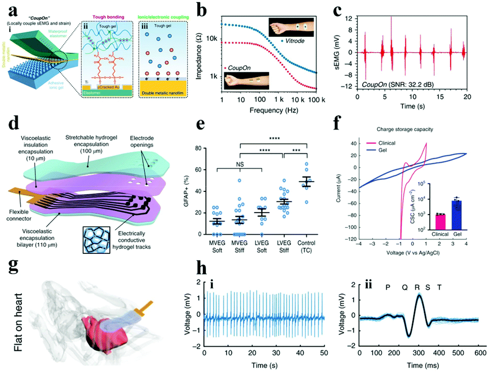 | ||
| Fig. 14 (a) Schematic of the (i) coupled electromechanical interface of the four-layer ionization hybrid (i.e., CoupOn), (ii) tough bonding, and (iii) ionic/electronic coupling; (b) impedance curves of the CoupOn and Vitrode electrode; and (c) sEMG of the CoupOn. Adapted with permission from ref. 231. Copyright 2020, Nature Publishing Group. (d) Illustration of the composition of the alginate hydrogel flexible electrode array material, (e) data graph recording primary cortical astrocytes inoculated on gels of disparate viscoelasticity (MVEG and LVEG) and stiffness (soft and stiff) in contrast to control tissue culture plastics (TC) after 120 h, where blue represents the nucleus, (f) CSC of viscoelastic electrode arrays and commercial grids, (g) diagram of the viscoelastic electrode array conforming to the mouse heart, (h) ECG of (i) mouse heart record and (ii) the average value of all beats superimposed (light blue displays a single cycle). Reproduced with permission from ref. 232. Copyright 2021, Nature Publishing Group. | ||
Besides, carbon-based materials have been one of the preferred materials for boosting the conductivity of ICH owing to the following advantages: (i) good conductivity, (ii) high surface area, and (iii) good stability in a wet environment. For example, Tringides et al.232 successfully prepared electrode arrays with ultra-soft viscoelasticity (Fig. 14d), using ion-conductive sodium alginate and carbon nanomaterials (i.e., CNT and graphene flakes) as a matrix and conductive additives, respectively. The softer and more viscoelastic gel (MVEG) not only has better biocompatibility than the harder and less viscoelastic gel (LVEG) (Fig. 14e), but also has a higher CSC compared to commercial grids (Fig. 14f). As monitored in Fig. 14g, the fully viscoelastic flexible electrode array can closely fit the surface of the heart and has appreciable ability in recording physiological signals (Fig. 14h). In short, under the premise of satisfying better electrochemical performance (Table S3†) and biocompatibility, the neural electrode, made from the materials transferring charge by ions and electrons, shows better signal transmission between the tissue and the external device.
4. Conclusion and outlook
Neural electrodes are key interfacial tools for electrophysiological communication between biological tissues and external electronic devices. Electrophysiological communication is a bidirectional process. In one way, the signals transfer from tissues, cross the electrode–tissue interfaces, deliver the electrode materials and finally are recorded by external devices. In reverse, the electrical signals transfer from the external devices to the tissues for stimulation. Thus, a good understanding of the transmission behavior of electrical signals in the tissues, the electrode–tissue interface and the electrode materials is helpful for building effective and stable neural electrode interfaces. In the tissues, the charge transfer was realized by ions, and the external electronic devices use electrons as the charge carriers to achieve high electrical conductivity. Therefore, neural electrodes with a synergistic charge transfer mechanism have more advantages in bidirectional information transfer. There are two ways to transmit electrical signals in the electrode–tissue interface. In one way, the signals cross the interface via electrical double layer capacitors. In the other way, the signal transfer is realized by a Faraday process. In brief, the signal transfer efficiency of the neural electrode depends on the impedance, charge storage capability, charge injection limitation and biocompatibility of the electrode.On the one hand, the electrochemical performance of the neural electrode is mainly determined by interface impedance, CSC, CIL, etc. Too high impedance will cause resolution degradation and signal distortion. The methods of reducing impedance mainly include: (i) improving the conformal ability between the neural interface; (ii) improving the adhesion ability between the electrode and the tissue; and (iii) modifying the microstructure on the electrode surface. In addition, the low CSC and CIL will affect the charge transfer and lead to the weakening of the signal strength, which can be solved by enlarging the specific surface area of the electrode material.
On the other hand, biocompatibility is also a key factor affecting the quality of signal transmission, which can reduce the inflammatory reaction of the tissues and further hinder the formation of tissue scars, so as to achieve a close contact between the electrode and the tissue. The main methods to enhance the biocompatibility of the neural electrode include reducing the stiffness of the electrode materials, selecting biocompatible materials for the fabrication of neural electrodes, and coating the electrode with biocompatible layers.
Although neural electrodes have made rapid progress in body–machine communication in recent years, several challenges remain to be overcome before such electronic devices can be seamlessly integrated into practical applications: (i) the weak adhesion of the electrode–tissue interface limits the signal transmission. This may be due to the high hydrophobicity and low bioaffinity of the material. Therefore, the preparation of conformal electrodes is urgently needed; (ii) the poor compliance of the electrode–tissue interface is still a rigorous problem. It not only requires the electrode to have good stretchability/bending stiffness (reducing mechanical failure), but also to have a lower elastic modulus (decreasing foreign body reaction), which ultimately avoids an increase in interfacial impedance and thus improves the electrode stimulation/recording efficiency; and (iii) the long-term stability of the electrode in the body still presents enormous challenges. This is not only due to the degradation of the electrode material in the body, but also due to mechanical delamination as a result of friction between the electrode and the tissue, resulting in a decrease in the electrical activity of the material.
In brief, neural electrodes are expected to achieve high efficiency, and precise and long term stable communication between the biological system and the external electronic systems in an electrical way. To realize this goal, we have to optimize the electrochemical performance and biocompatibility of neural electrodes by discovering new materials, designing novel micro/nanostructures and so on. Simultaneously, advanced microfabrication technology could promote the high throughput and accurate production of neural electrodes. It is believed that the development of neural electrodes could promote the evolution of neural-prosthesis, bioelectronic medicine, brain science, and so on.
Conflicts of interest
The authors declare that they have no conflict of interest.Acknowledgements
The authors acknowledge financial support from the National Natural Science Foundation of China (Grant No. 52173237, 51903068), the Natural Science Foundation of Heilongjiang Province, China (YQ2020E001) and the National Center for International Research on Intelligent Nano-Materials and Detection Technology in Environmental Protection (SDGH2105).References
- W. Wang, J. L. Collinger, M. A. Perez, E. C. Tyler-Kabara, L. G. Cohen, N. Birbaumer, S. W. Brose, A. B. Schwartz, M. L. Boninger and D. J. Weber, Phys. Med. and Rehabil. Clin., 2010, 21, 157–178 CrossRef PubMed.
- E. H. Chang, Bioelectron. Med., 2021, 7, 1–3 CrossRef PubMed.
- M. Zhang, Z. Tang, X. Liu and J. Van der Spiegel, Nat. Electron., 2020, 3, 191–200 CrossRef.
- N. Xue, I. D. Martinez, J. Sun, Y. Cheng and C. Liu, Biosens. Bioelectron., 2018, 112, 114–119 CrossRef CAS PubMed.
- J. A. Frank, M. J. Antonini and P. Anikeeva, Nat. Biotechnol., 2019, 37, 1013–1023 CrossRef CAS PubMed.
- A. Curt, H. J. Van Hedel, D. Klaus, V. Dietz and E. S. S. group, J. Neurotrauma, 2008, 25, 677–685 CrossRef PubMed.
- C. M. Proctor, A. Slézia, A. Kaszas, A. Ghestem, I. Del Agua, A. M. Pappa, C. Bernard, A. Williamson and G. G. Malliaras, Sci. Adv., 2018, 4, eaau1291 CrossRef CAS PubMed.
- J. Lam, J. Lee, C. Y. Liu, A. M. Lozano and D. J. Lee, Neuromodulation, 2021, 24, 171–186 CrossRef PubMed.
- M. Heravi, K. Maghooli, F. N. Rahatabad and R. Rezaee, Neurophysiology, 2020, 52, 375–387 CrossRef.
- Y. Shi, R. Liu, L. He, H. Feng, Y. Li and Z. Li, Smart Materials in Medicine, 2020 Search PubMed.
- C. Sung, W. Jeon, K. S. Nam, Y. Kim, H. Butt and S. Park, J. Mater. Chem. B, 2020, 8, 6624–6666 RSC.
- G. A. Woods, N. J. Rommelfanger and G. Hong, Matter, 2020, 3, 1087–1113 CrossRef PubMed.
- M. Zhang, R. Guo, K. Chen, Y. Wang, J. Niu, Y. Guo, Y. Zhang, Z. Yin, K. Xia and B. Zhou, Proc. Natl. Acad. Sci. U. S. A., 2020, 117, 14667–14675 CrossRef PubMed.
- W. M. Grill, S. E. Norman and R. V. Bellamkonda, Annu. Rev. Biomed. Eng., 2009, 11, 1–24 CrossRef CAS PubMed.
- M. Jia and M. Rolandi, Adv. Healthcare Mater., 2020, 9, 1901372 CrossRef CAS PubMed.
- L. Luan, J. T. Robinson, B. Aazhang, T. Chi, K. Yang, X. Li, H. Rathore, A. Singer, S. Yellapantula, Y. Fan, Z. Yu and C. Xie, Neuron, 2020, 108, 302–321 CrossRef CAS PubMed.
- S. M. Wellman, J. R. Eles, K. A. Ludwig, J. P. Seymour, N. J. Michelson, W. E. McFadden, A. L. Vazquez and T. D. Y. Kozai, Adv. Funct. Mater., 2018, 28, 1701269 CrossRef PubMed.
- W. M. Grill, S. E. Norman and R. V. Bellamkonda, Annu. Rev. Biomed. Eng., 2009, 11, 1–24 CrossRef CAS PubMed.
- M. Jia, J. Kim, T. Nguyen, T. Duong and M. Rolandi, Biopolymers, 2021, 112, e23433 CrossRef CAS PubMed.
- J. Rivnay, H. Wang, L. Fenno, K. Deisseroth and G. G. Malliaras, Sci. Adv., 2017, 3, e1601649 CrossRef PubMed.
- H. Yuk, B. Lu and X. Zhao, Chem. Soc. Rev., 2019, 48, 1642–1667 RSC.
- K. Krukiewicz, J. Britton, D. Więcławska, M. Skorupa, J. Fernandez, J. R. Sarasua and M. J. Biggs, Sci. Rep., 2021, 11, 1–10 CrossRef PubMed.
- F. E. Chan, H. M. Syu, T. Y. Wang, Z. T. Tang, C. N. Huang, J. F. Lee, T. Burnouf, S. H. Hu, P. C. Chen and W. C. Huang, Adv. Mater. Interfaces, 2021, 2100694 CrossRef CAS.
- R. A. Green, K. S. Lim, W. C. Henderson, R. T. Hassarati, P. J. Martens, N. H. Lovell and L. A. Poole-Warren, Living electrodes: tissue engineering the neural interface, in 2013 35th Annual International Conference of the IEEE Engineering in Medicine and Biology Society (EMBC), IEEE, 2013, pp. 6957–6960 Search PubMed.
- S. Liu, Y. Zhao, W. Hao, X. D. Zhang and D. Ming, Biosens. Bioelectron., 2020, 170, 112645 CrossRef CAS PubMed.
- A. S. Pranti, A. Schander, A. Bödecker and W. Lang, Sens. Actuators, B, 2018, 275, 382–393 CrossRef CAS.
- R. H. Dong, L. L. Wang, C. Hang, Z. Chen, X. Y. Liu, L. N. Zhong, J. Qi, Y. Q. Huang, S. Q. Liu, L. P. Wang, Y. Lu and X. Y. Jiang, Small, 2021, 17, 2006612 CrossRef CAS PubMed.
- L. Guo, M. M. Ma, N. Zhang, R. Langer and D. G. Anderson, Adv. Mater., 2014, 26, 1427–1433 CrossRef CAS PubMed.
- K. Tybrandt, D. Khodagholy, B. Dielacher, F. Stauffer, A. F. Renz, G. Buzsaki and J. Voros, Adv. Mater., 2018, 30, 1706520 CrossRef PubMed.
- H. Wark, R. Sharma, K. Mathews, E. Fernandez, J. Yoo, B. Christensen, P. Tresco, L. Rieth, F. Solzbacher and R. Normann, J. Neural Eng., 2013, 10, 045003 CrossRef CAS PubMed.
- Y. M. Chen, T. W. Chung, P. W. Wu and P. C. Chen, J. Alloys Compd., 2017, 692, 339–345 CrossRef CAS.
- D. Qi, Y. Liu, Z. Liu, L. Zhang and X. Chen, Adv. Mater., 2017, 29, 1602802 CrossRef PubMed.
- C. A. R. Chapman, N. Goshi and E. Seker, Adv. Funct. Mater., 2018, 28, 1703523 CrossRef.
- Q. Yang, T. Wei, R. T. Yin, M. Wu, Y. Xu, J. Koo, Y. S. Choi, Z. Xie, S. W. Chen and I. Kandela, Nat. Mater., 2021, 20, 1559–1570 CrossRef CAS PubMed.
- M. Zhang, Z. Tang, X. Liu and J. Van der Spiegel, Nat. Electron., 2020, 3, 191–200 CrossRef.
- A. R. Harris and G. G. Wallace, Curr. Opin. Electrochem., 2019, 16, 143–148 CrossRef CAS.
- D. T. Simon, E. O. Gabrielsson, K. Tybrandt and M. Berggren, Chem. Rev., 2016, 116, 13009–13041 CrossRef CAS PubMed.
- P. Fattahi, G. Yang, G. Kim and M. R. Abidian, Adv. Mater., 2014, 26, 1846–1885 CrossRef CAS PubMed.
- R. Biran, D. C. Martin and P. A. Tresco, Exp. Neurol., 2005, 195, 115–126 CrossRef CAS PubMed.
- J. W. Jeong, W. H. Yeo, A. Akhtar, J. J. S. Norton, Y. J. Kwack, S. Li, S. Y. Jung, Y. Su, W. Lee, J. Xia, H. Cheng, Y. Huang, W. S. Choi, T. Bretl and J. A. Rogers, Adv. Mater., 2013, 25, 6839–6846 CrossRef CAS PubMed.
- Y. Xie, N. Martini, C. Hassler, R. D. Kirch, T. Stieglitz, A. Seifert and U. G. Hofmann, Front. Neuroeng., 2014, 7, 34 Search PubMed.
- J. W. Salatino, K. A. Ludwig, T. D. Kozai and E. K. Purcell, Nat. Biomed. Eng., 2017, 1, 862–877 CrossRef CAS PubMed.
- E. R. Riva and S. Micera, Bioelectron. Med., 2021, 7, 1–10 CrossRef PubMed.
- K. Woeppel, Q. Yang and X. T. Cui, Curr. Opin. Biomed. Eng., 2017, 4, 21–31 CrossRef PubMed.
- S. M. Wellman, J. R. Eles, K. A. Ludwig, J. P. Seymour, N. J. Michelson, W. E. McFadden, A. L. Vazquez and T. D. Kozai, Adv. Funct. Mater., 2018, 28, 1701269 CrossRef PubMed.
- A. Sridharan, S. D. Rajan and J. Muthuswamy, J. Neural Eng., 2013, 10, 066001 CrossRef PubMed.
- C. Boehler, D. M. Vieira, U. Egert and M. Asplund, ACS Appl. Mater. Interfaces, 2020, 12, 14855–14865 CrossRef CAS PubMed.
- M. Skorupa, D. Wieclawska, D. Czerwinska-Glowka, M. Skonieczna and K. Krukiewicz, Polymers, 2021, 13, 1948 CrossRef CAS PubMed.
- Y. H. Kim, N. S. Baek, Y. H. Han, M. A. Chung and S. D. Jung, J. Neurosci. Methods, 2011, 202, 38–44 CrossRef CAS PubMed.
- W. He and R. V. Bellamkonda, Biomaterials, 2005, 26, 2983–2990 CrossRef CAS PubMed.
- L. Pan, P. Cai, L. Mei, Y. Cheng, Y. Zeng, M. Wang, T. Wang, Y. Jiang, B. Ji, D. Li and X. Chen, Adv. Mater., 2020, 32, 2003723 CrossRef CAS PubMed.
- J. H. Kim, S. R. Kim, H. J. Kil, Y. C. Kim and J. W. Park, Nano Lett., 2018, 18, 4531–4540 CrossRef CAS PubMed.
- C. A. Chapman, H. Chen, M. Stamou, J. Biener, M. M. Biener, P. J. Lein and E. Seker, ACS Appl. Mater. Interfaces, 2015, 7, 7093–7100 CrossRef CAS PubMed.
- E. Kolaya and B. L. Firestein, Biotechnol. Prog., 2021, e3179 CAS.
- N. Chen, L. Tian, A. C. Patil, S. Peng, I. H. Yang, N. V. Thakor and S. Ramakrishna, Nano Today, 2017, 14, 59–83 CrossRef CAS.
- E. Mtui, G. Gruener and M. T. FitzGerald, Clinical Neuroanatomy and Neuroscience E-Book, Elsevier Health Sciences, 2011 Search PubMed.
- P. S. Kaeser, L. Deng, Y. Wang, I. Dulubova, X. Liu, J. Rizo and T. C. Südhof, Cell, 2011, 144, 282–295 CrossRef CAS PubMed.
- E. R. Kandel, J. H. Schwartz, T. M. Jessell, S. A. Siegelbaum and A. J. Hudspeth, Principles of Neural Science, 5th edn, 2012 Search PubMed.
- S. F. Cogan, Annu. Rev. Biomed. Eng., 2008, 10, 275–309 CrossRef CAS PubMed.
- D. R. Merrill, in Implantable Neural Prostheses 2: Techniques and Engineering Approaches, ed. D. Zhou and E. Greenbaum, Springer New York, New York, NY, 2010 Search PubMed.
- D. R. Merrill, M. Bikson and J. G. Jefferys, J. Neurosci. Methods, 2005, 141, 171–198 CrossRef PubMed.
- R. Dong, L. Wang, C. Hang, Z. Chen, X. Liu, L. Zhong, J. Qi, Y. Huang, S. Liu and L. Wang, Small, 2021, 17, 2006612 CrossRef CAS PubMed.
- Y. H. Kim, H. Koo, M. S. Kim and S. D. Jung, Sens. Actuators, B, 2018, 273, 718–725 CrossRef CAS.
- R. Thakur, A. R. Nair, A. Jin and G. Y. Fridman, Fabrication of a Self-Curling Cuff with a Soft, Ionically Conducting Neural Interface, in 2019 41st Annual International Conference of the IEEE Engineering in Medicine and Biology Society (EMBC), IEEE, 2019, pp. 3750–3753 Search PubMed.
- R. Green, Nat. Biomed. Eng., 2019, 3, 9–10 CrossRef PubMed.
- C. Wu, A. Liu, S. Chen, X. Zhang, L. Chen, Y. Zhu, Z. Xiao, J. Sun, H. Luo and H. Fan, ACS Appl. Mater. Interfaces, 2019, 11, 22152–22163 CrossRef CAS PubMed.
- N. K. Guimard, N. Gomez and C. E. Schmidt, Prog. Polym. Sci., 2007, 32, 876–921 CrossRef CAS.
- E. Zeglio, A. L. Rutz, T. E. Winkler, G. G. Malliaras and A. Herland, Adv. Mater., 2019, 31, 1806712 CrossRef PubMed.
- R. Liu, S. Zhao and J. Liu, ACS Appl. Electron. Mater., 2020, 3, 101–118 CrossRef.
- G. Hong, T. M. Fu, M. Qiao, R. D. Viveros, X. Yang, T. Zhou, J. M. Lee, H. G. Park, J. R. Sanes and C. M. Lieber, Science, 2018, 360, 1447–1451 CrossRef CAS PubMed.
- T. Rose and L. Robblee, IEEE Trans. Biomed. Eng., 1990, 37, 1118–1120 CrossRef CAS PubMed.
- D. Borkholder, J. Bao, N. Maluf, E. Perl and G. Kovacs, J. Neurosci. Methods, 1997, 77, 61–66 CrossRef CAS PubMed.
- S. F. Cogan, P. R. Troyk, J. Ehrlich and T. D. Plante, IEEE Trans. Biomed. Eng., 2005, 52, 1612–1614 CrossRef PubMed.
- R. Balint, N. J. Cassidy and S. H. Cartmell, Acta Biomater., 2014, 10, 2341–2353 CrossRef CAS PubMed.
- S. Baek, R. A. Green and L. A. Poole Warren, J. Biomed. Mater. Res., Part A, 2014, 102, 2743–2754 CrossRef PubMed.
- D. A. Schwarz, M. A. Lebedev, T. L. Hanson, D. F. Dimitrov, G. Lehew, J. Meloy, S. Rajangam, V. Subramanian, P. J. Ifft, Z. Li, A. Ramakrishnan, A. Tate, K. Z. Zhuang and M. A. L. Nicolelis, Nat. Methods, 2014, 11, 670–676 CrossRef CAS PubMed.
- T. A. Fofonoff, S. M. Martel, N. G. Hatsopoulos, J. P. Donoghue and I. W. Hunter, IEEE Trans. Biomed. Eng., 2004, 51, 890–895 CrossRef PubMed.
- B. Ghane-Motlagh and M. Sawan, A review of microelectrode array technologies: design and implementation challenges, in 2013 2nd International Conference on Advances in Biomedical Engineering, IEEE, 2013, pp. 38–41 Search PubMed.
- S. Takeuchi, T. Suzuki, K. Mabuchi and H. Fujita, J. Micromech. Microeng., 2003, 14, 104–107 CrossRef.
- D. Qi, Z. Liu, M. Yu, Y. Liu, Y. Tang, J. Lv, Y. Li, J. Wei, B. Liedberg, Z. Yu and X. Chen, Adv. Mater., 2015, 27, 3145–3151 CrossRef CAS PubMed.
- K. Moxon, S. Hallman, A. Aslani, N. Kalkhoran and P. Lelkes, J. Biomater. Sci., Polym. Ed., 2007, 18, 1263–1281 CrossRef CAS PubMed.
- M. Li, Q. Zhou and Y. Y. Duan, Sens. Actuators, B, 2015, 221, 179–186 CrossRef CAS.
- F. Shuang, H. Deng, A. B. Shafique, S. Marsh, D. Treiman, K. Tsakalis and K. E. Aifantis, Mater. Lett., 2020, 260, 126885 CrossRef.
- D. Qi, Z. Liu, M. Yu, Y. Liu, Y. Tang, J. Lv, Y. Li, J. Wei, B. Liedberg, Z. Yu and X. Chen, Adv. Mater., 2015, 27, 3145–3151 CrossRef CAS PubMed.
- Y. H. Kim, G. H. Kim, N. S. Baek, Y. H. Han, A. Y. Kim, M. A. Chung and S. D. Jung, J. Micromech. Microeng., 2013, 23, 097001 CrossRef CAS.
- H. Yoon, P. Hankins, S. Oh, R. E. Harbaugh and V. K. Varadan, J. Nanotechnol. Eng. Med., 2010, 1, 021006 CrossRef.
- V. Urbanová, Y. Li, K. Vytřas, B. Yvert and A. Kuhn, J. Electroanal. Chem., 2011, 656, 91–95 CrossRef.
- C. A. R. Chapman, H. Chen, M. Stamou, J. Biener, M. M. Biener, P. J. Lein and E. Seker, ACS Appl. Mater. Interfaces, 2015, 7, 7093–7100 CrossRef CAS PubMed.
- R. Zhang, D. Yao, P. A. Valdés-Sosa, F. Li, P. Li, T. Zhang, T. Ma, Y. Li and P. Xu, J. Neural Eng., 2015, 12, 066024 CrossRef PubMed.
- E. Seker, Y. Berdichevsky, M. R. Begley, M. L. Reed, K. J. Staley and M. L. Yarmush, Nanotechnology, 2010, 21, 125504 CrossRef PubMed.
- S. Choi, S. I. Han, D. Jung, H. J. Hwang, C. Lim, S. Bae, O. K. Park, C. M. Tschabrunn, M. Lee, S. Y. Bae, J. W. Yu, J. H. Ryu, S. W. Lee, K. Park, P. M. Kang, W. B. Lee, R. Nezafat, T. Hyeon and D. H. Kim, Nat. Nanotechnol., 2018, 13, 1048–1056 CrossRef CAS PubMed.
- R. Dong, L. Wang, C. Hang, Z. Chen, X. Liu, L. Zhong, J. Qi, Y. Huang, S. Liu, L. Wang, Y. Lu and X. Jiang, Small, 2021, 17, 2006612 CrossRef CAS PubMed.
- L. D. Scanlan, R. B. Reed, A. V. Loguinov, P. Antczak, A. Tagmount, S. Aloni, D. T. Nowinski, P. Luong, C. Tran, N. Karunaratne, D. Pham, X. X. Lin, F. Falciani, C. P. Higgins, J. F. Ranville, C. D. Vulpe and B. Gilbert, ACS Nano, 2013, 7, 10681–10694 CrossRef CAS PubMed.
- I. G. Theodorou, K. H. Müller, S. Chen, A. E. Goode, V. Yufit, M. P. Ryan and A. E. Porter, ACS Biomater. Sci. Eng., 2017, 3, 2336–2347 CrossRef CAS PubMed.
- Q. Wang, Y. Yu and J. Liu, Adv. Eng. Mater., 2018, 20, 1700781 CrossRef.
- C. Jin, J. Zhang, X. Li, X. Yang, J. Li and J. Liu, Sci. Rep., 2013, 3, 1–7 Search PubMed.
- R. Liu, X. Yang, C. Jin, J. Fu, W. Chen and J. Liu, Appl. Phys. Lett., 2013, 103, 193701 CrossRef.
- Y. Yu, J. Zhang and J. Liu, PLoS One, 2013, 8, e58771 CrossRef CAS PubMed.
- P. H. Kuo, T. H. Tzeng, Y. C. Huang, Y. H. Chen, Y. C. Chang, Y. L. Ho, J. T. Wu, H. H. Lee, P. J. Lai and K. Y. Liu, PLoS One, 2014, 9, e104543 CrossRef PubMed.
- J. Zhang, L. Sheng, C. Jin and J. Liu, arXiv preprint arXiv:1404.5931, 2014.
- F. Liu, Y. Yu, L. Yi and J. Liu, Sci. Bull., 2016, 61, 939–947 CrossRef CAS.
- S. De and J. N. Coleman, ACS Nano, 2010, 4, 2713–2720 CrossRef CAS PubMed.
- H. C. Tian, J. Q. Liu, D. X. Wei, X. Y. Kang, C. Zhang, J. C. Du, B. Yang, X. Chen, H. Y. Zhu and Y. N. NuLi, Biomaterials, 2014, 35, 2120–2129 CrossRef CAS PubMed.
- Y. Lu, X. Liu, R. Hattori, C. Ren, X. Zhang, T. Komiyama and D. Kuzum, Adv. Funct. Mater., 2018, 28, 1800002 CrossRef PubMed.
- Y. Lu, X. Liu and D. Kuzum, Curr. Opin. Biomed. Eng., 2018, 6, 138–147 CrossRef.
- S. K. Lee, H. Kim and B. S. Shim, Carbon Lett., 2013, 14, 63–75 CrossRef.
- S. Zhao, G. Li, C. Tong, W. Chen, P. Wang, J. Dai, X. Fu, Z. Xu, X. Liu and L. Lu, Nat. Commun., 2020, 11, 1–12 Search PubMed.
- C. H. Chen, C. T. Lin, W. L. Hsu, Y. C. Chang, S. R. Yeh, L. J. Li and D. J. Yao, Nanomedicine, 2013, 9, 600–604 CrossRef CAS PubMed.
- D. Kuzum, H. Takano, E. Shim, J. C. Reed, H. Juul, A. G. Richardson, J. de Vries, H. Bink, M. A. Dichter, T. H. Lucas, D. A. Coulter, E. Cubukcu and B. Litt, Nat. Commun., 2014, 5, 5259 CrossRef CAS PubMed.
- K. Wang, C. L. Frewin, D. Esrafilzadeh, C. Yu, C. Wang, J. J. Pancrazio, M. Romero-Ortega, R. Jalili and G. Wallace, Adv. Mater., 2019, 31, 1805867 CrossRef PubMed.
- N. V. Apollo, M. I. Maturana, W. Tong, D. A. X. Nayagam, M. N. Shivdasani, J. Foroughi, G. G. Wallace, S. Prawer, M. R. Ibbotson and D. J. Garrett, Adv. Funct. Mater., 2015, 25, 3551–3559 CrossRef CAS.
- Y. Lu, H. Lyu, A. G. Richardson, T. H. Lucas and D. Kuzum, Sci. Rep., 2016, 6, 1–9 CrossRef PubMed.
- A. Bourrier, P. Shkorbatova, M. Bonizzato, E. Rey, Q. Barraud, G. Courtine, R. Othmen, V. Reita, V. Bouchiat and C. Delacour, Adv. Healthcare Mater., 2019, 8, 1801331 CrossRef PubMed.
- C. Chiu, X. He and H. Liang, Electrochim. Acta, 2013, 94, 42–48 CrossRef CAS.
- L. J. Wang, L. Li, J. Yu, Y. Wu, H. He, X. Ouyang, X. Zhao, Y. C. Yen and L. J. Lee, Carbon, 2014, 79, 294–301 CrossRef CAS.
- B. Koerbitzer, P. Krauss, C. Nick, S. Yadav, J. J. Schneider and C. Thielemann, 2D Mater., 2016, 3, 024004 CrossRef.
- M. Shein, A. Greenbaum, T. Gabay, R. Sorkin, M. David-Pur, E. Ben-Jacob and Y. Hanein, Biomed. Microdevices, 2009, 11, 495–501 CrossRef CAS PubMed.
- M. Meyyappan, Carbon nanotubes: science and applications, CRC press, 2004 Search PubMed.
- M. Bottini, N. Rosato and N. Bottini, Biomacromolecules, 2011, 12, 3381–3393 CrossRef CAS PubMed.
- C. R. Butson and C. C. McIntyre, Clin. Neurophysiol., 2005, 116, 2490–2500 CrossRef PubMed.
- M. Vafaiee, R. Mohammadpour, M. Vossoughi, E. Asadian, M. Janahmadi and P. Sasanpour, Front. Bioeng. Biotechnol., 2021, 8, 1465 Search PubMed.
- T. B. Nguyen-Vu, H. Chen, A. M. Cassell, R. J. Andrews, M. Meyyappan and J. Li, IEEE Trans. Biomed. Eng., 2007, 54, 1121–1128 Search PubMed.
- A. A. John, A. P. Subramanian, M. V. Vellayappan, A. Balaji, H. Mohandas and S. K. Jaganathan, Int. J. Nanomed., 2015, 10, 4267 CAS.
- N. Chen, B. Luo, A. C. Patil, J. Wang, G. G. L. Gammad, Z. Yi, X. Liu, S. C. Yen, S. Ramakrishna and N. V. Thakor, ACS Nano, 2020, 14, 8059–8073 CrossRef CAS PubMed.
- K. Foremny, W. S. Konerding, A. Behrens, P. Baumhoff, U. P. Froriep, A. Kral and T. Doll, Nanomaterials, 2021, 11, 1029 CrossRef CAS PubMed.
- C. M. Lin, Y. T. Lee, S. R. Yeh and W. Fang, Biosens. Bioelectron., 2009, 24, 2791–2797 CrossRef CAS PubMed.
- H. C. Su, C. M. Lin, S. J. Yen, Y. C. Chen, C. H. Chen, S. R. Yeh, W. Fang, H. Chen, D. J. Yao, Y. C. Chang and T. R. Yew, Biosens. Bioelectron., 2010, 26, 220–227 CrossRef CAS PubMed.
- J. Zhang, X. Liu, W. Xu, W. Luo, M. Li, F. Chu, L. Xu, A. Cao, J. Guan, S. Tang and X. Duan, Nano Lett., 2018, 18, 2903–2911 CrossRef CAS PubMed.
- M. David-Pur, L. Bareket-Keren, G. Beit-Yaakov, D. Raz-Prag and Y. Hanein, Biomed. Microdevices, 2014, 16, 43–53 CrossRef CAS PubMed.
- F. Vitale, S. R. Summerson, B. Aazhang, C. Kemere and M. Pasquali, ACS Nano, 2015, 9, 4465–4474 CrossRef CAS PubMed.
- L. Lu, X. Fu, Y. Liew, Y. Zhang, S. Zhao, Z. Xu, J. Zhao, D. Li, Q. Li, G. B. Stanley and X. Duan, Nano Lett., 2019, 19, 1577–1586 CrossRef CAS PubMed.
- K. Wang, R. Y. Tang, X. B. Zhao, J. J. Li, Y. R. Lang, X. X. Jiang, H. J. Sun, Q. X. Lin and C. Y. Wang, Nanoscale, 2015, 7, 18677–18685 RSC.
- C. M. Voge and J. P. Stegemann, J. Neural Eng., 2011, 8, 011001 CrossRef PubMed.
- A. Ansaldo, E. Castagnola, E. Maggiolini, L. Fadiga and D. Ricci, ACS Nano, 2011, 5, 2206–2214 CrossRef CAS PubMed.
- H. Li, J. Wang and Y. Fang, Nanoscale Adv., 2020, 2, 3095–3102 RSC.
- A. Shoval, C. Adams, M. David-Pur, M. Shein, Y. Hanein and E. Sernagor, Front. Neuroeng., 2009, 2, 4 CrossRef CAS PubMed.
- E. W. Keefer, B. R. Botterman, M. I. Romero, A. F. Rossi and G. W. Gross, Nat. Nanotechnol., 2008, 3, 434–439 CrossRef CAS PubMed.
- G. Piret, C. Hébert, J. P. Mazellier, L. Rousseau, E. Scorsone, M. Cottance, G. Lissorgues, M. O. Heuschkel, S. Picaud, P. Bergonzo and B. Yvert, Biomaterials, 2015, 53, 173–183 CrossRef CAS PubMed.
- M. Levin, G. Pezzulo and J. M. Finkelstein, Annu. Rev. Biomed. Eng., 2017, 19, 353–387 CrossRef CAS PubMed.
- Y. J. Jo, J. Ok, S. Y. Kim and T. I. Kim, Adv. Mater. Technol., 2021, 2001273 Search PubMed.
- C. Cea, G. D. Spyropoulos, P. Jastrzebska-Perfect, J. J. Ferrero, J. N. Gelinas and D. Khodagholy, Nat. Mater., 2020, 19, 679–686 CrossRef CAS PubMed.
- K. Feron, R. Lim, C. Sherwood, A. Keynes, A. Brichta and P. C. Dastoor, Int. J. Mol. Sci., 2018, 19, 2382 CrossRef PubMed.
- M. Jia, H. Dechiruji, J. Selberg, P. Pansodtee, J. Mathews, C. Wu, M. Levin, M. Teodorescu and M. Rolandi, APL Mater., 2020, 8, 091106 CrossRef CAS.
- T. Arbring Sjöström, M. Berggren, E. O. Gabrielsson, P. Janson, D. J. Poxson, M. Seitanidou and D. T. Simon, Adv. Mater. Technol., 2018, 3, 1700360 CrossRef.
- H. R. Lee, C. C. Kim and J. Y. Sun, Adv. Mater., 2018, 30, 1704403 CrossRef PubMed.
- C. Wang, T. Yokota and T. Someya, Chem. Rev., 2021, 121, 2109–2146 CrossRef CAS PubMed.
- K. Jeong, S. Park, G. Y. Jung, S. H. Kim, Y. H. Lee, S. K. Kwak and S. Y. Lee, J. Am. Chem. Soc., 2019, 141, 5880–5885 CrossRef CAS PubMed.
- X. Liu, J. Liu, S. Lin and X. Zhao, Mater. Today, 2020, 36, 102–124 CrossRef CAS.
- B. L. Ekerdt, C. M. Fuentes, Y. Lei, M. M. Adil, A. Ramasubramanian, R. A. Segalman and D. V. Schaffer, Adv. Healthcare Mater., 2018, 7, 1800225 CrossRef PubMed.
- H. Zhan and D. W. Löwik, Adv. Funct. Mater., 2019, 29, 1808505 CrossRef.
- D. Fan, U. Staufer and A. Accardo, Bioengineering, 2019, 6, 113 CrossRef CAS PubMed.
- W. Sun, H. Jiang, X. Wu, Z. Xu, C. Yao, J. Wang, M. Qin, Q. Jiang, W. Wang and D. Shi, Nano Res., 2019, 12, 115–119 CrossRef CAS.
- Z. Sun, C. Song, C. Wang, Y. Hu and J. Wu, Mol. Pharm., 2019, 17, 373–391 Search PubMed.
- H. Jung, M. K. Kim, J. Y. Lee, S. W. Choi and J. Kim, Adv. Funct. Mater., 2020, 30, 2004407 CrossRef CAS.
- C. A. Dreiss, Curr. Opin. Colloid Interface Sci., 2020, 48, 1–17 CrossRef CAS.
- D. Han, Y. Li, X. Liu, B. Li, Y. Han, Y. Zheng, K. W. K. Yeung, C. Li, Z. Cui and Y. Liang, Chem. Eng. J., 2020, 396, 125194 CrossRef CAS.
- A. Hasan, A. Khattab, M. A. Islam, K. A. Hweij, J. Zeitouny, R. Waters, M. Sayegh, M. M. Hossain and A. Paul, Adv. Sci., 2015, 2, 1500122 CrossRef PubMed.
- Y. M. Kim, H. H. Park, D. H. Hwang, Y. Cui, E. M. Lee, S. Yahn, J. K. Lee, S. C. Song and B. G. Kim, Nat. Commun., 2017, 8, 1–14 CrossRef CAS.
- G. An, F. Guo, X. Liu, Z. Wang, Y. Zhu, Y. Fan, C. Xuan, Y. Li, H. Wu and X. Shi, Nat. Commun., 2020, 11, 1–12 Search PubMed.
- R. Chen, H. B. Chen, P. P. Xue, W. G. Yang, L. Z. Luo, M. Q. Tong, B. Zhong, H. L. Xu, Y. Z. Zhao and J. D. Yuan, J. Mater. Chem. B, 2021, 9, 1107–1122 RSC.
- R. Yang, G. Li, C. Zhuang, P. Yu, T. Ye, Y. Zhang, P. Shang, J. Huang, M. Cai and L. Wang, Sci. Adv., 2021, 7, eabg3816 CrossRef CAS PubMed.
- S. Zhao, P. Tseng, J. Grasman, Y. Wang, W. Li, B. Napier, B. Yavuz, Y. Chen, L. Howell, J. Rincon, F. G. Omenetto and D. L. Kaplan, Adv. Mater., 2018, 30, 1800598 CrossRef PubMed.
- X. Sun, F. Yao and J. Li, J. Mater. Chem., 2020, 8, 18605–18623 RSC.
- H. Banerjee, M. Suhail and H. Ren, Biomimetics, 2018, 3, 15 CrossRef PubMed.
- J. Xu, R. Jing, X. Ren and G. Gao, J. Mater. Chem., 2020, 8, 9373–9381 RSC.
- X. Sun, P. Tyagi, S. Agate, M. G. McCord, L. A. Lucia and L. Pal, Carbohydr. Polym., 2020, 234, 115898 CrossRef CAS PubMed.
- X. Y. Wen, Z. Liu, J. Wang, X. Y. Tang, W. Wang, X. J. Ju, R. Xie and L. Y. Chu, ACS Appl. Mater. Interfaces, 2019, 11, 20386–20393 CrossRef CAS PubMed.
- H. Sheng, X. Wang, N. Kong, W. Xi, H. Yang, X. Wu, K. Wu, C. Li, J. Hu, J. Tang, J. Zhou, S. Duan, H. Wang and Z. Suo, Extreme Mech. Lett., 2019, 30, 100510 CrossRef.
- J. Nam, H. K. Lim, N. H. Kim, J. K. Park, E. S. Kang, Y. T. Kim, C. Heo, O. S. Lee, S. G. Kim, W. S. Yun, M. Suh and Y. H. Kim, ACS Nano, 2020, 14, 664–675 CrossRef CAS PubMed.
- W. C. Huang, X. C. Ong, I. S. Kwon, C. Gopinath, L. E. Fisher, H. Wu, G. K. Fedder, R. A. Gaunt and C. J. Bettinger, Adv. Funct. Mater., 2018, 28, 1801059 CrossRef.
- J. Liu, S. Qu, Z. Suo and W. Yang, Natl. Sci. Rev., 2021, 8, nwaa254 CrossRef CAS PubMed.
- N. Park and J. Kim, Adv. Intell. Syst., 2020, 2, 1900135 CrossRef.
- Z. Lei, Q. Wang, S. Sun, W. Zhu and P. Wu, Adv. Mater., 2017, 29, 1700321 CrossRef PubMed.
- R. S. Hsu, P. Y. Chen, J. H. Fang, Y. Y. Chen, C. W. Chang, Y. J. Lu and S. H. Hu, Adv. Sci., 2019, 6, 1900520 CrossRef PubMed.
- C. Yang and Z. Suo, Nat. Rev. Mater., 2018, 3, 125–142 CrossRef CAS.
- C. H. Yang, B. Chen, J. J. Lu, J. H. Yang, J. Zhou, Y. M. Chen and Z. Suo, Extreme Mech. Lett., 2015, 3, 59–65 CrossRef.
- Y. Ye, Y. Zhang, Y. Chen, X. Han and F. Jiang, Adv. Funct. Mater., 2020, 30, 2003430 CrossRef CAS.
- Y. Liang, L. Ye, X. Sun, Q. Lv and H. Liang, ACS Appl. Mater. Interfaces, 2019, 12, 1577–1587 CrossRef PubMed.
- Z. Jia, Y. Zeng, P. Tang, D. Gan, W. Xing, Y. Hou, K. Wang, C. Xie and X. Lu, Chem. Mater., 2019, 31, 5625–5632 CrossRef CAS.
- S. J. Devaki, R. K. Narayanan and S. Sarojam, Mater. Lett., 2014, 116, 135–138 CrossRef CAS.
- Y. Zhou, C. Wan, Y. Yang, H. Yang, S. Wang, Z. Dai, K. Ji, H. Jiang, X. Chen and Y. Long, Adv. Funct. Mater., 2019, 29, 1806220 CrossRef.
- H. Sheng, X. Wang, N. Kong, W. Xi, H. Yang, X. Wu, K. Wu, C. Li, J. Hu and J. Tang, Extreme Mech. Lett., 2019, 30, 100510 CrossRef.
- C. Keplinger, J. Y. Sun, C. C. Foo, P. Rothemund, G. M. Whitesides and Z. Suo, Science, 2013, 341, 984–987 CrossRef CAS PubMed.
- K. Nagamine, S. Chihara, H. Kai, H. Kaji and M. Nishizawa, Sens. Actuators, B, 2016, 237, 49–53 CrossRef CAS.
- J. Y. Sun, C. Keplinger, G. M. Whitesides and Z. Suo, Adv. Mater., 2014, 26, 7608–7614 CrossRef CAS PubMed.
- K. C. Spencer, J. C. Sy, K. B. Ramadi, A. M. Graybiel, R. Langer and M. J. Cima, Sci. Rep., 2017, 7, 1952 CrossRef PubMed.
- H. Wu, G. Yang, K. Zhu, S. Liu, W. Guo, Z. Jiang and Z. Li, Adv. Sci., 2021, 8, 2001938 CrossRef CAS PubMed.
- L. Chen, Z. Wang, Z. Zhan, M. Xie, G. Duan, P. Cheng, Y. Chen and H. Duan, Mater. Today Phys., 2021, 19, 100404 CrossRef CAS.
- Q. Zhang, X. Liu, L. Duan and G. Gao, J. Mater. Chem., 2020, 8, 4515–4523 RSC.
- J. Y. Sun, C. Keplinger, G. M. Whitesides and Z. Suo, Adv. Mater., 2014, 26, 7608–7614 CrossRef CAS PubMed.
- K. Dong, X. Liu, H. Dong, X. Zhang and S. Zhang, Chem. Rev., 2017, 117, 6636–6695 CrossRef CAS PubMed.
- D. Zhang, H. Qiao, W. Fan, K. Zhang, Y. Xia and K. Sui, Mater. Today Phys., 2020, 15, 100246 CrossRef.
- G. Li, Z. Deng, M. Cai, K. Huang, M. Guo, P. Zhang, X. Hou, Y. Zhang, Y. Wang, Y. Wang, X. Wu and C. F. Guo, npj Flexible Electron., 2021, 5, 23 CrossRef CAS.
- Z. Wu, X. Yang and J. Wu, ACS Appl. Mater. Interfaces, 2021, 13, 2128–2144 CrossRef CAS PubMed.
- X. J. Zha, S. T. Zhang, J. H. Pu, X. Zhao, K. Ke, R. Y. Bao, L. Bai, Z. Y. Liu, M. B. Yang and W. Yang, ACS Appl. Mater. Interfaces, 2020, 12, 23514–23522 CrossRef CAS PubMed.
- J. L. Li, R. Y. Wang, X. Y. Liu and H. H. Pan, J. Phys. Chem. B, 2009, 113, 5011–5015 CrossRef CAS PubMed.
- Z. Zhao, S. Zhuo, R. Fang, L. Zhang, X. Zhou, Y. Xu, J. Zhang, Z. Dong, L. Jiang and M. Liu, Adv. Mater., 2018, 30, 1804435 CrossRef PubMed.
- J. Song, S. Chen, L. Sun, Y. Guo, L. Zhang, S. Wang, H. Xuan, Q. Guan and Z. You, Adv. Mater., 2020, 32, 1906994 CrossRef CAS PubMed.
- F. Chen, D. Zhou, J. Wang, T. Li, X. Zhou, T. Gan, S. Handschuh-Wang and X. Zhou, Angew. Chem., 2018, 130, 6678–6681 CrossRef.
- S. Shi, X. Peng, T. Liu, Y. N. Chen, C. He and H. Wang, Polymer, 2017, 111, 168–176 CrossRef CAS.
- J. Wu, Z. Wu, H. Xu, Q. Wu, C. Liu, B. R. Yang, X. Gui, X. Xie, K. Tao and Y. Shen, Mater. Horiz., 2019, 6, 595–603 RSC.
- H. Gao, Z. Zhao, Y. Cai, J. Zhou, W. Hua, L. Chen, L. Wang, J. Zhang, D. Han and M. Liu, Nat. Commun., 2017, 8, 1–8 CrossRef CAS PubMed.
- X. Pan, Q. Wang, R. Guo, Y. Ni, K. Liu, X. Ouyang, L. Chen, L. Huang, S. Cao and M. Xie, J. Mater. Chem., 2019, 7, 4525–4535 RSC.
- W. Xie, J. Duan, H. Wang, J. Li, R. Liu, B. Yu, S. Liu and J. Zhou, J. Mater. Chem., 2018, 6, 24114–24119 RSC.
- J. Luo, Y. Xing, C. Sun, L. Fan, H. Shi, Q. Zhang, Y. Li, C. Hou and H. Wang, Chem. Eng. J., 2022, 427, 130886 CrossRef CAS.
- V. Saunier, E. Flahaut, M. C. Blatché, C. Bergaud and A. Maziz, Biosens. Bioelectron., 2020, 165, 112413 CrossRef CAS PubMed.
- D. Qi, Z. Liu, M. Yu, Y. Liu, Y. Tang, J. Lv, Y. Li, J. Wei, B. Liedberg and Z. Yu, Adv. Mater., 2015, 27, 3145–3151 CrossRef CAS PubMed.
- R. Liu, S. Zhao and J. Liu, ACS Appl. Electron. Mater., 2021, 3, 101–118 CrossRef CAS.
- R. Green and M. R. Abidian, Adv. Mater., 2015, 27, 7620–7637 CrossRef CAS PubMed.
- N. A. Kotov, J. O. Winter, I. P. Clements, E. Jan, B. P. Timko, S. Campidelli, S. Pathak, A. Mazzatenta, C. M. Lieber and M. Prato, Adv. Mater., 2009, 21, 3970–4004 CrossRef CAS.
- W. K. Oh, O. S. Kwon and J. Jang, Polym. Rev., 2013, 53, 407–442 CrossRef CAS.
- S. P. Lacour, S. Benmerah, E. Tarte, J. FitzGerald, J. Serra, S. McMahon, J. Fawcett, O. Graudejus, Z. Yu and B. Morrison, Med. Biol. Eng. Comput., 2010, 48, 945–954 CrossRef PubMed.
- L. Guo, M. Ma, N. Zhang, R. Langer and D. G. Anderson, Adv. Mater., 2014, 26, 1427–1433 CrossRef CAS PubMed.
- D. P. Qi, Z. Y. Liu, Y. Liu, Y. Jiang, W. R. Leow, M. Pal, S. W. Pan, H. Yang, Y. Wang, X. Q. Zhang, J. C. Yu, B. Li, Z. Yu, W. Wang and X. D. Chen, Adv. Mater., 2017, 29, 10 Search PubMed.
- D. Qi, Z. Liu, Y. Liu, Y. Jiang, W. R. Leow, M. Pal, S. Pan, H. Yang, Y. Wang, X. Zhang, J. Yu, B. Li, Z. Yu, W. Wang and X. Chen, Adv. Mater., 2017, 29, 1702800 CrossRef PubMed.
- E. Cuttaz, J. Goding, C. Vallejo-Giraldo, U. Aregueta-Robles, N. Lovell, D. Ghezzi and R. A. Green, Biomater. Sci., 2019, 7, 1372–1385 RSC.
- J. Che, Y. Xiao, X. Zhu and X. Sun, Polym. Int., 2008, 57, 750–755 CrossRef CAS.
- N. K. Guimard, N. Gomez and C. E. Schmidt, Prog. Polym. Sci., 2007, 32, 876–921 CrossRef CAS.
- K. A. Ludwig, J. D. Uram, J. Yang, D. C. Martin and D. R. Kipke, J. Neural Eng., 2006, 3, 59 CrossRef PubMed.
- A. R. Harris, S. J. Morgan, J. Chen, R. M. Kapsa, G. G. Wallace and A. G. Paolini, J. Neural Eng., 2012, 10, 016004 CrossRef PubMed.
- R. A. Green, N. H. Lovell and L. A. Poole Warren, Acta Biomater., 2010, 6, 63–71 CrossRef CAS PubMed.
- M. Cucchi, C. Gruener, L. Petrauskas, P. Steiner, H. Tseng, A. Fischer, B. Penkovsky, C. Matthus, P. Birkholz and H. Kleemann, Sci. Adv., 2021, 7, eabh0693 CrossRef PubMed.
- S. Guzzo, S. Carli, B. Pavan, A. Lunghi, M. Murgia and M. Bianchi, Nanomaterials, 2021, 11, 2022 CrossRef CAS PubMed.
- J. Ouyang, SmartMat, 2021, 2, 263–285 CrossRef.
- C. Wang, K. He, J. Li and X. Chen, SmartMat, 2021, 2, 252–262 CrossRef.
- A. Blau, A. Murr, S. Wolff, E. Sernagor, P. Medini, G. Iurilli, C. Ziegler and F. Benfenati, Biomaterials, 2011, 32, 1778–1786 CrossRef CAS PubMed.
- E. A. Cuttaz, C. A. R. Chapman, O. Syed, J. A. Goding and R. A. Green, Adv. Sci., 2021, 8, 2004033 CrossRef CAS PubMed.
- L. P. Wang, W. Wang, L. Di, Y. N. Lu and J. Y. Wang, Colloids Surf., B, 2010, 80, 72–78 CrossRef CAS PubMed.
- M. R. Abidian and D. C. Martin, Biomaterials, 2008, 29, 1273–1283 CrossRef CAS PubMed.
- M. R. Abidian, J. M. Corey, D. R. Kipke and D. C. Martin, Small, 2010, 6, 421–429 CrossRef CAS PubMed.
- P. Cai, C. Wan, L. Pan, N. Matsuhisa, K. He, Z. Cui, W. Zhang, C. Li, J. Wang and J. Yu, Nat. Commun., 2020, 11, 1–12 Search PubMed.
- C. M. Tringides, N. Vachicouras, I. de Lázaro, H. Wang, A. Trouillet, B. R. Seo, A. Elosegui-Artola, F. Fallegger, Y. Shin and C. Casiraghi, Nat. Nanotechnol., 2021, 1–11 Search PubMed.
- N. Chen, B. Luo, A. C. Patil, J. Wang, G. G. L. Gammad, Z. Yi, X. Liu, S. C. Yen, S. Ramakrishna and N. V. Thakor, ACS Nano, 2020, 14, 8059–8073 CrossRef CAS PubMed.
- J. Goding, C. Vallejo-Giraldo, O. Syed and R. Green, J. Mater. Chem. B, 2019, 7, 1625–1636 RSC.
- J. Chung, A. Khot, B. M. Savoie and B. W. Boudouris, ACS Macro Lett., 2020, 9, 646–655 CrossRef CAS.
- F. Fu, J. Wang, H. Zeng and J. Yu, ACS Mater. Lett., 2020, 2, 1287–1301 CrossRef CAS.
- S. Yang, L. Jang, S. Kim, J. Yang, K. Yang, S. W. Cho and J. Y. Lee, Macromol. Biosci., 2016, 16, 1653–1661 CrossRef CAS PubMed.
- A. R. Spencer, A. Primbetova, A. N. Koppes, R. A. Koppes, H. Fenniri and N. Annabi, ACS Biomater. Sci. Eng., 2018, 4, 1558–1567 CAS.
Footnote |
| † Electronic supplementary information (ESI) available. See DOI: 10.1039/d1nr07226a |
| This journal is © The Royal Society of Chemistry 2022 |