 Open Access Article
Creative Commons Attribution 3.0 Unported Licence
Recent advances, design guidelines, and prospects of flexible organic/inorganic thermoelectric composites
Qinghui
Jiang†
 *a,
Junyou
Yang
 *a,
Peter
Hing
b and
Haitao
Ye†
 *b
*b
aSchool of Materials Science and Engineering, Huazhong University of Science and Technology, Wuhan, China. E-mail: qhjiang@hust.edu.cn; jyyang@hust.edu.cn
bSchool of Engineering, University of Leicester, University Road, Leicester LE1 7RH, UK. E-mail: haitao.ye@leicester.ac.uk
First published on 24th June 2020
Abstract
Thermoelectrics can recover waste heat, environmental heat or heats from different sources and convert it to electricity. Inorganic or metal thermoelectrics have higher ZT values and efficiency; however, they are also expensive, rigid or have poor mechanical properties, and they contain toxic or rare elements. Organic thermoelectrics have low cost, flexible mechanical properties, and facile and rapid formation; however, they have very low ZT values and efficiency compared with inorganic materials. Organic–inorganic composite thermoelectrics can benefit from both properties and are also extremely competitive for commercial applications. This review will focus on flexible organic–inorganic composite thermoelectrics and devices as well as their challenges.
1. Introduction
Many serious energy problems and environmental pollution issues are associated with rapid industrial development worldwide. The low carbon manufacturing concept was proposed to reduce CO2 emissions, energy costs, and reliance on fossil fuels. In power plants, steel and iron factories, car engines and everyday electronics, a large proportion of energy from fossil fuels is lost worldwide as wasted heat (about 60% of the energy generated by fuels worldwide). Most of this energy is low-heat: waste heat below 100 °C accounts for 42%, and waste heat between 100 °C and 200 °C accounts for 22%.1–3 The development of clean and environmentally friendly new energy conversion materials has drawn considerable attention to recycle waste heat and achieve cost-effective energy conservation. Meanwhile, micro-sensors and intelligent equipment for human health monitoring, intelligent human–machine interaction, the Internet of Things, cloud platforms, and other technologies are urgently needed to obtain continuous electricity from the environment. Thermoelectric materials can realize thermoelectric generation and cooling by utilizing the Seebeck effect and Peltier effect. With no mechanical moving parts, no noxious emission, light weight, lack of pollution and compact structures, thermoelectric materials have broad application prospects in this field as a clean energy form and as chips/laser coolers that can realize direct conversion between waste heat/ambient temperature differences and energy.4For wider commercial applications, thermoelectric materials need a higher figure of merit (ZT), which requires a higher Seebeck coefficient, higher electrical conductivity, and lower thermal conductivity. Over the past 10–15 years, new materials design ideas (mainly involving nanostructures), new promising bulk compounds, and novel synthesis and processing methods have fuelled much research activity in thermoelectrics. These efforts have led to the discovery of novel inorganic materials with ZT values larger than 1: these include thin-film superlattices, nanostructures, and semiconductors with engineered band gaps.5–7 Unfortunately, many of these systems require the use of toxic or rare elements and often have very expensive synthesis procedures. Current commercial materials contain large amounts of rare elements, such as tellurium or toxic Pb elements (for example, Bi2Te3 or PbTe) with ZT values near 1.0–1.5; this prohibits future scale-up.8 Moreover, the current manufacture of thermoelectric generators (TEGs) requires sawing of TE materials, which results in substantial amounts of expensive raw-material waste. At present, for widespread application of TEGs as a waste heat recovery technology, the following scientific hurdles must be overcome: (1) synthesis of low-cost, environmentally benign and nontoxic high performance thermoelectric materials,9,10 and (2) fabrication of shape-engineerable device/systems for practical application.
Organic molecules and polymer semiconductors have emerged as new thermoelectric materials. These materials can be tailored “on demand” by means of chemistry to afford complex systems that can perform proper electric and thermal transport properties. Thermoelectric polymers have the characteristics of light weight, low cost, flexible mechanical properties, facile processing, abundant resources and environmental friendliness. Organic small molecules (OSMs) have the advantages of easy purification, no batch-to-batch variation, well-defined molecular and electronic structures, and intermolecular packing properties. Thus, OSMs have become a new frontier research area of molecular functional materials.11 However, they have rather low ZT values and efficiency compared with inorganic materials. Compositing is proven to be effective in enhancing thermoelectric performance, and organic–inorganic thermoelectric composites can have the benefits of both properties; thus, they are extremely competitive for commercial applications. This review will focus on organic–inorganic composite thermoelectrics and devices as well as their future challenges.
2. Scientific mechanism of organic/inorganic thermoelectric composites
2.1 Percolation theory
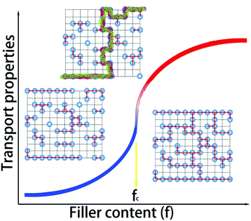
Percolation theory was initially adopted to analyze physical phenomena near the onset of global connectivity in disordered systems. Geometric percolation transition (the percolation threshold) is defined as follows: the particles of a minor phase (i.e., fillers) come into contact with each other, and a continuous cluster extends throughout the system. This percolation theory is very effective to account for the physical properties of heterogeneous multicomponents (or phases).12 When the content is near this threshold, dramatic nonlinear changes occur in the physical properties of the composites, including their electrical or thermal conductivity, as shown in Fig. 1. The transport properties of the system near the conductive-insulating transition can be described by percolation equations with power laws of (σ ∝ (fc − fV)−s) for fV < fc, and σ ∝ (fV − fc)t for fV > fc, where fV is the volumetric fraction of the conductive second phase, fc is the percolation threshold, t is the critical exponent in the conducting region, and s is the critical exponent in the insulating region.Atomic-scale or molecular percolation phenomena of electric and thermal conductivity were already found in inorganic and organic thermoelectric materials with quasi-disordered structures.13–15 For example, digenite CuxS exhibits fast-ion conduction with liquid-like mobility. At high temperature, copper ions are randomly located between the closely packed sulphur ions and jump to other positions via unoccupied interstices. The copper vacancies (i.e. unoccupied interstices) can be regarded as the conductive media in a percolation system. In one sulphur hexagonal unit cell (6-CuxS), there are 6 sulphur atoms and 18 interstices. In a simple rigid model, the content of conductive minor phase (fV) can be calculated as (18 − 6x)/24. Near the percolation threshold value (fc ∼ 0.3) in the conductive region, a 60% enhancement of the ZT value can be obtained.16 In WTe2/CoSb3 inorganic composites, the locally percolated highly conductive WTe2 pellets improved the electrical conductivity of the composite, and the pronounced bipolar peak of pristine CoSb3 was quickly suppressed upon the addition of WTe2. As a result, the power factor was markedly enhanced by up to 59 times that of the pristine CoSb3 upon compositing.17 Horta et al. prepared polyaniline–poly(vinylacetate) (PANI–PVAc) organic nanocomposites via latex technology.18 The relationship between the electrical properties (piezoresistive, thermoresistive and thermoelectric behaviour) and the PANI–PVAc ratio complied well with the percolation model related to morphological and structural changes. The composites with 10–30 wt% PANI had suitable electrical conductivities and beneficial thermostability of the polymer matrix for sensor applications. This effect plays a key role in organic/inorganic composites and guides the design and optimization of material compositions, microstructures and performance.19,20
2.2 Grain boundaries and interface effects
Three thermoelectric parameters, namely electric conductivity, Seebeck coefficient and thermal conductivity, are interdependent on each other. Much effort has been made to decouple these parameters, such as phonon engineering and band engineering.21–23 Since the lattice thermal conductivity can be relatively dependent, phonon engineering is popular to improve the ZT values of thermoelectrics. The introduction of atomic-scale lattice disorder, nanoscale precipitates and mesoscale grain boundaries can effectively scatter phonons with different mean free paths, which can lead to a decrease of the lattice thermal conductivity and enhance the ZT values.24Andrei et al. studied the size dependence of electrical conductivity in PEDOT:PSS with different layers fabricated via spin coating on glass plates. The electrical conductivity significantly depended on the thickness of the layers. As indicated by AFM, UV-vis, Raman, and XPS measurements, this behaviour could be attributed to a combination of factors at two different scales: percolation between the grains and reorganization of the conjugated chains.25 Based on similar mechanisms, most inorganic/organic thermoelectric nanocomposites are fabricated in order to obtain lower thermal conductivity and higher ZT values near the critical condition of percolation. However, the interfaces between the organic and inorganic phases are not clear, which normally leads to high resistivity and weakens the expected effects.26,27
2.3 Superlattice effects/energy filter effects
Normally, the coupling of electrical and thermal transport leads to difficulty in individually tailoring the phonon properties without deterioration of the electronic transport. In 1993, LD Hicks et al.28 proposed that the power factor of a thermoelectric superlattice can be increased from an enhanced density of states near the Fermi energy according to the quantum confinement effect. Another phonon-blocking/electron-transmitting superlattice can utilize the acoustic mismatch between the different layers and obviously reduce the thermal conductivity of the lattice. Scientists subsequently constructed inorganic/inorganic superlattices, such as PbSe0.98Te0.02/PbTe and Bi2Te3/Sb2Te3 superlattices.29 Using these effects, ZT values of 1.5–2.0 near room temperature were obtained. Experiments confirmed that the structure would lead to a significant increase in the Seebeck coefficient and a linear decrease in thermal conductivity with increasing thickness of the superlattice.Organic/inorganic nanostructures with superlattices can potentially show hybrid properties synergistically derived from both the host and the guest, such as micro-scale composites with the percolation phenomenon. Meanwhile, the inter-insertion of (conjugated) polymers and layered inorganic materials can afford novel electrical and thermal properties.30 For example, M. G. Kanatzidis et al.31 fabricated a nanoscale molecular composite via the encapsulation of polyaniline (PANI) in MoS2, leading to unusual charge-transport properties. C. L. Wan et al.32,33 fabricated inorganic/organic TiS2[(HA)x(DMSO)w] superlattices via electrochemical intercalation and solvent exchange. These hybrid inorganic/organic superlattices possessed a high electronic power factor from the inorganic component TiS2. The coupling between the inorganic and organic layers plays a key role in the scattering of phonon transport. As a result of the significant reduction in the thermal conductivity, a ZTin-plane value of 0.28 was obtained in TiS2[(HA)0.08(H2O)0.22(DMSO)0.03] near 100 °C, as shown in Fig. 2.
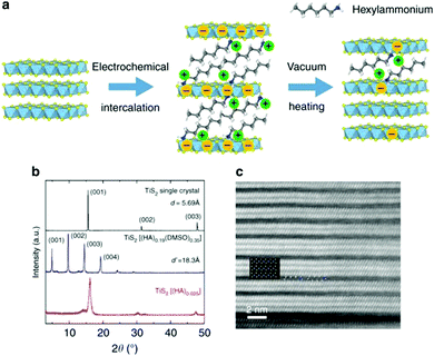 | ||
| Fig. 2 (a) Schematic of the electrochemical intercalation process. (b) XRD patterns of TiS2 single crystal and its related superlattice structures. (c) Magnified STEM image of TiS2(HA)0.025. (Reproduced from ref. 33 with permission from Nature Communication.). | ||
With the successful exfoliation of monolayer graphene, two-dimensional materials (such as hexagonal boron nitride, MoS2, and phosphene) have drawn strong attention. It has been found that the transport barrier of electrons can be regulated via changing the number of layers of two-dimensional materials in the heterojunction based on van der Waals heterojunctions, such as graphene/phosphene/graphene, graphene/BN/graphene, and silicone/transition metal sulphides.34–36 As a result, the thermal conductivity in the plane direction of the vertical heterojunction will be much lower than that of the interface bonded by covalent bonds.37 This indicates that the construction of van der Waals heterojunctions is an effective strategy to optimize the thermoelectric performance of materials. Because the cross-linking of organic molecular layers can effectively decouple the interaction between atomic layers, organic/inorganic van der Waals heterojunction superlattices have more important research significance. In 2018, Wang et al.36 successfully prepared organic/inorganic superlattices such as BP/CTAB (hexadecyltrimethylammonium bromide), SnSe/CTAB and Bi2Se3 by electrochemical molecular embedding. These general synthesis routes and ideas can be extended to thermoelectric research and lead to extraordinary improvement of ZT values in the future.
The energy filter effect is partly classified as a superlattice effect, which can explain the increase of the Seebeck coefficient in 0–3 type thermoelectric nanocomposites. For example, an n-type Ag2Se/Ag/CuAgSe composite film has an ultrahigh power factor of 2231.5 μW m−1 K−2 at 300 K. There are energy barriers near the Ag2Se/Ag, CuAgSe/Ag and Ag2Se/CuAgSe interfaces. Fig. 3 shows the equilibrium band diagrams of Ag/Ag2Se, CuAgSe/Ag2Se and Ag/CuAgSe. The blend band gap between the two semiconductors and metallic Ag NPs forms a Schottky barrier. In the composite, low-energy carriers are blocked, while high-energy carriers can jump across the interfaces. This leads to the coexistence of high carrier concentration and a decent Seebeck coefficient, which results in an ultrahigh power factor.38
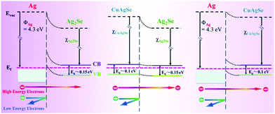 | ||
| Fig. 3 Equilibrium band diagrams for Ag/Ag2Se, CuAgSe/Ag2Se and Ag/CuAgSe.38 | ||
3. Fabrication techniques and future challenges
The fabrication of thermoelectric composite films or bulk materials with excellent electrical transport properties remains a major bottleneck for high-performance flexible TE materials and devices. Currently, several fabrication methods are used, as discussed in the following sections.3.1 Electro-spinning technique
The electro-spinning technique is used to fabricate ultra-fine fibres with high surface-to-volume ratios and controllable compositions starting from molten polymers or a solution. The electro-spun fibres have a homogeneous chemical composition and uniform particle size distribution. This technique is based on the application of an electric field to a drop of fluid on the tip of a spinneret. As shown in Fig. 4a, a syringe pump is used to eject the solution at a controllable speed through the needle, and the collector is placed near the tip. A high voltage is applied between the tip and the collector, which leads to evaporation of the solvent and the formation of continuous fibres.39,40 To date, electro-spun polymer nanofibres have been successfully investigated in biomedical applications and nanocatalysis due to their high surface-to-volume ratio, low density, and flexibility. Dalton et al. used electro-spinning to fabricate p-type and n-type carbon fibres from mixtures of lignin and PAN.41 Meanwhile, inorganic fibres, such as NaCo2O4,42 Mg2Si,43 and PbTe (Fig. 4b),44 were successfully fabricated with some flexibility. In thermoelectric fibres, grain boundaries and interfaces can also scatter phonons, thereby lowering the thermal conductivity and optimizing the transport properties of the fibres. However, it is still challenging to obtain fibre composites with good thermoelectric properties. Wang et al. prepared carbon nanotube and polyaniline (PANI) composite nanofibres by in situ polymerization combined with electro-spinning processes. Carbon nanotubes and PANI backbone chains are oriented along the fibre axis due to strong chemical interactions, as shown in Fig. 3c and d. High orientation of the PANI backbone chains reduces the π–π conjugated defects, boosts the effective degree of electron delocalization and therefore heightens the carrier mobility in PANI, which results in doubled improvement of the power factor in the orientation direction.45 This indicates that the electro-spinning process provides an effective route to design a flexible composite with high thermoelectric performance through high ordering of the backbone chain structure. Highly flexible textiles containing n- and p-junctions prepared by this process can harvest environmental heat in the desirable through-thickness direction, and a power output of up to 8.6 W m−2 is obtained when the temperature difference is 200 °C.46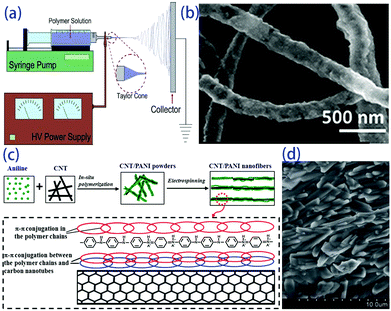 | ||
| Fig. 4 (a) Scheme of a conventional electrospinning setup,39 (b) electrospun hollow PbTe nanofibers,44 (c) schematic of the formation mechanism and (d) SEM image of CNT/PANI nanofibers.45 | ||
3.2 Hot pressing or spark plasma sintering
During the hot pressing process, a uniaxial pressure is applied while heating a powder compact which is placed in a graphite or alloy mould. This process was developed and applied earlier in powder metallurgy to fabricate high-temperature alloys and ceramics with high density under relatively low sintering temperatures.47 Recently, hot pressing has become a relatively mature technique for the preparation of thermoelectric nanocomposites.38,48–50Because of the thermoplasticity of the polymer matrix, most dense organic–inorganic composites can be fabricated via a simple homemade hot pressing device. J. Kim et al.51 prepared n-type carbon bucky paper with carbon nanotubes and a PVDF composite via hot pressing at 60 °C in 6 MPa for 3 min. Bi0.5Sb1.5Te3/epoxy thick films with high orientation were prepared via brush-printing and hot pressing on polyimide substrates.52 For a prototype flexible TE cooling device with Bi0.5Sb1.5Te3/epoxy thick films, the stable temperature difference of the prototype device reached 6 °C under a working current of 0.06 A.
Spark plasma sintering (SPS) is an efficient sintering method that allows rapid consolidation at comparatively low temperatures,16,53–55 and it is especially suitable for fabricating thermoelectric composite materials.56,57 Ge et al. fabricated a PEDOT:PSS/Cu2SnSe3 nanocomposite polymer bulk via spark plasma sintering (SPS) at 100 °C. The polymer powder transformed into a homogeneous polymer bulk after SPS (the process is shown in Fig. 5), and this product showed much better properties than a sample processed using a cold press. The sample with 33 wt% nanoparticles showed the highest ZT of the samples tested, with a value of 0.04 at 45 °C; this is 20 times higher than the 0.002 value of a pristine PEDOT:PSS bulk sample.56
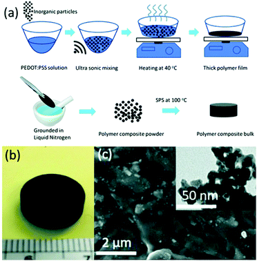 | ||
| Fig. 5 (a) Process used to synthesize bulk polymers. (b) Photograph of a polymer bulk sample after applying SPS. (c) CSS polymer bulk with an inset showing a TEM image of Cu2SnSe3 nanoparticles. (Reproduced from ref. 56 with permission from The Royal Society of Chemistry.). | ||
3.3 Solution processing
Solution processing methods are highly suitable for the preparation of thermoelectric materials with organic matrices. Among them, hydrothermal synthesis is an effective method to prepare inorganic fillers without aggregation.58 The inorganic filler solution is blended with organic thermoelectrics and finally dropped on a pre-cleaned or vacuum-filtered glass slide, followed by rapid drying under vacuum to form an organic–inorganic thermoelectric composite film.59 For example, Miao et al.60 used a hydrothermal method to obtain a reductive graphene material (RGO) with high electrical conductivity; they then prepared an RGO/Te nanowire bilayer composite film on a glass fiber filter substrate by drop coating. The results showed that the film has a maximum power factor of 80 μW (m K2)−1. Lin et al.61 added cuprous selenide powder to mixed solvent at room temperature and stirred the solution for 10 min; by this process, Cu2Se ink could be directly obtained. A uniform film was prepared on a sapphire substrate by a simple spin coating process, and its power factor reached 0.62 mW (m K2)−1. After repeated bending 1000 times, about 90% of the thermoelectric performance could be maintained.3.4 Paste processing or silk-screen printing
As a traditional printing method, screen printing is regarded as a manufacturing method for rapidly and efficiently fabricating thermoelectric thin films and thermoelectric devices because of its low cost, simple operation, scalable production, and even curved surface printing.62,63Generally, the preparation of the organic–inorganic composite paste for screen printing is accomplished by subjecting previously prepared organic and inorganic components to solution treatment. In order to achieve a better deposition effect on the substrate during printing, the organic–inorganic composite paste has basic viscosity requirements. Other challenges include anti-oxidation during printing and curing and post-treatment of the composite paste after screen printing. Many types of thermoelectric composite films have been fabricated by screen printing, such as Bi2Te3 and PbTe-based materials.64–67 Wang et al. obtained a PANI/Te composite film by combining Te nanorods with conductive polymer polyaniline (PANI) via screen printing, and a ZT value of 0.22 was obtained at 110 °C. The prototype device with 10 legs of PANI/Te-Ag branches had a maximum output voltage and output power of 29.9 mV and 0.73 μW respectively at ΔT = 40 °C.68 Varghese et al. fabricated flexible Bi2Te3 films and devices by screen printing. The paste was synthesized via a microwave-stimulated wet-chemical method. Thermoelectric films were printed onto a polyimide substrate followed by cold compaction and annealing (the process is shown in Fig. 6). The thermoelectric device with the printed films has a power density of 4 mW cm−2 at ΔT = 60 °C. As a highly scalable and low-cost process, screen printing technology has great potential applications to fabricate flexible thermoelectric energy harvesting and cooling devices.
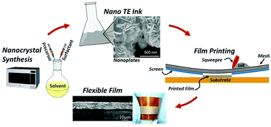 | ||
| Fig. 6 Schematic of the overall fabrication process of flexible thermoelectric films, including nanocrystal synthesis, nano-ink processing, screen printing of thermoelectric films on a flexible substrate, and sintered flexible films. (Reproduced from ref. 63 with permission from Scientific Reports.). | ||
3.5 Layer deposition technique
The basic principle of traditional deposition technology, in short, is to deposit foreign matter on the surface of a substrate to form a composite film. During the deposition processes of thermoelectric organic–inorganic composites, organic materials are usually used as substrates or working electrodes, and inorganic materials are deposited on the surface of the organic materials to form 2–2 composite systems. Additionally, OSM materials can be deposited layer by layer with inorganic materials to fabricate superlattice structures.30,69,70 Although many layer deposition techniques can be used to deposit inorganic materials, such as pulsed laser deposition and physical vapour deposition, there are two traditional technologies to realize commercial layer-by-layer deposition for organic/inorganic composites, as follows.Because electrochemical deposition can only occur on conductive substrates, a feasible choice to prepare organic–inorganic composite films is to electrochemically deposit inorganic thermoelectric materials on organic intrinsically conductive polymers (ICP) for use as a working electrode. Culebras et al. prepared thin Te/PEDOT films by depositing Te on the PEDOT working electrode by a simple electrochemical deposition method.74 The Seebeck coefficient of the film increased from 9 μV K−1 to 230 μV K−1 after deposition, leading to a higher power factor (320 μW (m K2)−1). However, there was a significant increase in the electric resistivity due to the high porosity of the Te polycrystalline film. It will be very challenging in the future to increase the electric conductivity of films obtained by electrochemical deposition.
Molecular layer deposition (MLD) is another technique similar to ALD that uses sequential, self-limiting reactions to deposit thin films in molecular units. The combination of ALD and MLD technology allows us to alternately deposit metal oxides and organics on a substrate to produce a homogeneous organic–inorganic superlattice material rather than simply depositing inorganic materials on organic substrates, as shown in Fig. 7. The oxide-organic interface may scatter more phonons or lead to confinement effects, which enhances the thermoelectric properties of the materials.87 Karttunen et al. used ALD/MLD to fabricate thermoelectric ZnO-organic superlattice thin films on cotton textile substrates; the films had excellent flexibility and exhibited lower thermal conductivity than the pristine ZnO film.88 It is foreseeable that ALD and MLD technologies will play important roles in the field of flexible thermoelectric materials and devices.
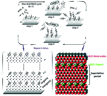 | ||
| Fig. 7 ALD/MLD cycle schematic of the growth of superlattice structures: (1) pulse the metal precursor (e.g. diethylzinc) on the surface, (2) purge the excess precursor and byproduct molecules with inert gas, (3) pulse the organic precursor, and (4) purge the excess organic precursor and byproduct molecules again. A superlattice film of organic/inorganic layers with controlled thickness is fabricated via repeating the ALD/MLD cycle. (Reproduced from ref. 87 with permission from The Royal Society of Chemistry.). | ||
3.6 Inkjet printing
In recent years, inkjet printing technology has been introduced into the manufacture of electronic devices (OLED, PCB, etc.) due to its unique advantages of no-contact, additive and digitized processes. The simple spin-spray process can be also included in this category; it is one of the most effective strategies for the rapid development of uniform thermoelectric films with relatively complex structures.89According to different working principles, inkjet printing technology can be divided into two types: continuous inkjet printing and drop-on-demand inkjet printing. The latter has gradually become the mainstream in the market. At present, drop-on-demand inkjet technology mainly includes two types, namely thermal inkjet technology and piezoelectric inkjet technology. Thermal inkjet technology generates vapor bubbles inside the ink by rapidly heating the ink (generally heating above the boiling point of the ink); this is more suitable for water-based ink than organic solvents because of the need to heat and evaporate the ink.90
Utilizing the inverse piezoelectric effect, the piezo inkjet printer shrinks the ink through a piezoelectric element controlled by an electrical signal to cause the ink to be squeezed away from the nozzle and finally ejected onto the substrate to form a pattern. This technology reduces energy consumption, prolongs the service life of the machine, and overcomes the limitations of the ink materials; therefore, it is a promising approach after overcoming the challenges of thermoelectric inks.90–93 While ensuring the good thermoelectric performance of the ink, it is also necessary to take into account the printability of the ink, which poses a great challenge for the design of thermoelectric composite material systems and is also key to the realization of inkjet printing of high-quality thermoelectric materials. This is because (1) the inherent complexity of the thermoelectric composite system leads to dynamic changes in the thermoelectric properties and fluid properties of the ink, caused by the type and proportion of composite; (2) in order to meet the printable and post-treatment requirements of thermoelectric inks, they often contain additives such as surfactants, binders, thickeners, and stabilizers, which undoubtedly increases the complexity of the ink system.94,95
There have been some reports on the inkjet printing of thermoelectric materials, including Bi2Te3, graphene, carbon nanotubes and polymers,96–101 which mostly focus on regulation of the printing performance of thermoelectric inks. Chen et al.99 prepared Bi2Te3 thermoelectric nanowires and then dispersed them in deionized water in an ultrasonic bath to form a jettable ink, which was finally printed onto a glass substrate. The Seebeck coefficient of the film was about 140 μV K−1, similar to that of bulk Bi2Te3. Kato et al.102 studied the preparation of a coatable ink of Bi0.4 Sb1.6Te3, PEDOT:PSS and an organic additive (PAA). Chen et al. inkjet-printed Bi2Te3 and Bi0.5Sb1.5Te3 nanowires as inks to onto polyimide to form a highly flexible TEG. After annealing at 450 °C, maximum power factors of 180 μW (m K2)−1 and 110 μW (m K2)−1 were obtained for the Bi2Te3 and Bi0.5Sb1.5Te3 films.103 The power of the generator could reach ∼130 nW at ΔT = 32 °C, and it maintained its performance even after 50 bending experiments (with a tight radius of curvature of ∼10 mm), as shown in Fig. 8. In future, if thermoelectric inks with long-term stability, suitable fluid properties and excellent thermoelectric properties can be obtained, it will be possible to produce low-cost, high-efficiency, miniaturized and expandable flexible TEGs by inkjet printing.
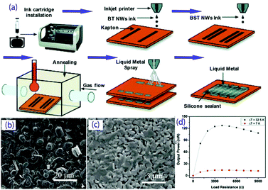 | ||
| Fig. 8 (a) Fabrication schematic for the development of the inkjet-printed TEG device; SEM micrographs of the printed BST50 (b) and BT50 (c) nanowires annealed at 450 °C for 10 min; (d) output power of the printed TEG as a function of load resistance. (Reproduced from ref. 103 with permission from The Royal Society of Chemistry.). | ||
3.7 3D printing
As an “additive manufacturing technology”, in recent years, 3D printing technology has received increasing attention worldwide; this includes fused deposition molding (FDM), stereolithography apparatus (SLA), laminated object manufacturing (LOM) and selective laser sintering (SLS). Due to its advantages of rapid prototyping, high material utilization, printability of complex entities and flexible product design, 3D printing has been used to fabricate thermoelectric devices. He et al. fabricated a thermoelectric organic–inorganic composite material with ultra-low thermal conductivity and a ZT value of up to 0.12 by preparing a Bi0.5Sb1.5Te3/photosensitizer composite in combination with SLA technology.104 Kim et al. prepared a Bi2Te3-based thermoelectric ink using Sb2Te3 chalcogenidometallate ions as a binder and fabricated thermoelectric devices using an extrusion-based 3D printer built in-house.105 The TE materials they prepared with different shapes obtained ZT values of 0.6 (N-type) and 0.9 (P-type). The cylindrical TEG, which was fabricated using a 3D printing method, achieved a power density of 1.4 mW cm−2 at 40 °C. Wang et al. prepared a thermoelectric composite wire for FDM-based 3D printing by extrusion synthesis using polylactic acid (PLA) as a matrix and Bi0.5Sb1.5Te3 as the filler.106 The thermoelectric properties and the flexibility of the composite wires could be controlled by tailoring the content of the fillers and the matrix. These results indicate that 3D printing has great potential in the field of thermoelectric composite materials and has the opportunity to be applied to the rapid production of flexible thermoelectric materials and devices.1074. Chalcogenide-based composites
Chalcogenide-based thermoelectric materials have better thermoelectric properties, especially higher Seebeck coefficients; these include Bi2Te3-based thermoelectric materials. When Bi2Te3 is combined with organic thermoelectric materials such as poly(3,4-ethylenedioxythiophene) polystyrene sulfonate (PEDOT:PSS) and polylactic acid, it shows good thermoelectric properties and can have the advantages of mechanical flexibility and low price at the same time. Generally, a composite material composed of two components according to the mixture model has thermoelectric properties between those of its two single components. A π–π conjugate interaction between the carbon nanotubes/polymer will lead to novel phenomena for the hybrid model. However, the weakening of this interaction and the instability of the operations have led to some different results between research groups.4.1 Bi2Te3-based composite
Bi2Te3-based thermoelectric materials exhibit similar work functions to other organic thermoelectric materials, such as PEDOT:PSS, polylactic acid, poly(3-hexylthiophene) (P3HT) and epoxy resin; the low-energy carriers are scattered due to the interface between the inorganic nanoparticles and the organic matrix. This scattering effect enables organic–inorganic composite thermoelectric materials to obtain higher Seebeck coefficients without substantially lowering their electrical conductivity; therefore, they show superior performance.| Material | Electrical conductivity (S cm−1) | Seebeck coefficient (μV K−1) | Thermal conductivity (W m−1 K−1) | PF (μW (m K2)−1) | ZT | Fabrication method | Ref. |
|---|---|---|---|---|---|---|---|
| P3HT(matrix) | 320 | 269 | 0.16⊥ 0.23‖ | 62.4 | 0.1 | Template method | 108 |
| P3HT/Bi2Te3 | ∼1000 | ∼117 | 0.54–0.86 | 13.6 | 0.1 | Solution mixing | 59 |
| P3HT/Bi2Te3 | 450 | 118 | — | 6.3 | — | Hydrothermal synthesis | 59 |
| PEDOT:PSS/Bi0.5Sb1.5Te3 | 16.2 | 377 | 1.5 | — | 0.05 | SPS | 57 |
| PEDOT/Bi2Te3 | — | — | 0.7 | 1350 | 0.58 | Template-assisted nanofabrication | 109 |
| PEDOT/Bi2Te3 | ∼62 | ∼145 | — | 131 | — | Solution mixing | 110 |
| PEDOT:PSS/Bi2Te3/Sb2Te3 | 247.3 | 33.8 | — | 28.3 | — | Aerosol jet printing method | 111 |
| PLA/Bi0.5Sb1.5Te3 | — | 200 | — | 11.3 | 0.011 | Extrusion | 106 |
| PEDOT:PSS/Bi2Te3 | 421 | 18.6 | 0.07 ± 0.02 | 9.9 | 0.04 | Physical mixing method | 112 |
| PANI/MWCNT | ∼6000 | ∼30 | ∼0.5 | 5 | — | Template method | 113 |
| P3HT/CNT | — | — | — | 49.0 | — | Solution mixing | 114 |
| PANI/SWNT | 769 | 65 | 0.43 | 176 | 0.12 | Solution process | 115 |
| PEDOT:PSS/PAVC/SCNT | 1.35 × 10⁵ | 41 | 0.2–0.4 | 160 | — | Solution mixing | 116 |
| PEDOT:PSS/rGO/F-C60 | — | — | — | 83.2 | 0.10 | Lithiation method | 117 |
| PANI/GNP | 59 | 33 | 13 | — | 1.51 × 10⁻⁴ | Solution mixing | 118 |
| PEDOT:PSS/C60/Graphene | 10![[thin space (1/6-em)]](https://www.rsc.org/images/entities/char_2009.gif) 000–70 000–70![[thin space (1/6-em)]](https://www.rsc.org/images/entities/char_2009.gif) 000 000 |
— | 0.2–2 | — | 0.067 | 119 |
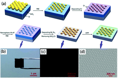 | ||
| Fig. 9 (a) Scheme of the fabrication of the organic/inorganic hybrid film via by nanosphere lithography, (b) digital photograph of closely packed monolayer PS nanospheres on a SiO2/Si substrate after etching, SEM image of (c) Bi2Te3 nanoparticle arrays prepared by using 100 nm PS nanospheres as patterns and (d) PEDOT/Bi2Te3(100) hybrid films.109 | ||
5. Carbon-based composites
In addition to traditional inorganic thermoelectric materials, nanostructured carbon materials such as carbon nanotubes and graphene are often used as fillers for composite thermoelectric materials because carbon nanotubes and graphene have high electrical conductivity, which improves the electrical conductivity of the composite. Moreover, because the carbon-based nanomaterial has a conjugated π–π structure and a large specific surface area, which facilitates intimate contact with the conductive polymer, the interfacial effect on the phonon scattering is enhanced; therefore, the composite has lower thermal conductivity. Finally, the synergy between this carbon material and the conductive polymer endows the polymer with good thermoelectric properties. For example, Muller et al.126 found that the thermoelectric properties of polymer materials can be improved by combining conductive polymer materials with CNTs. The thermoelectric properties of carbon-based composites can be improved not only by controlling the level of polymer doping, but also by changing the processing process.127 Therefore, these composite materials have received extensive attention, and carbon nanotubes are the most commonly used fillers in thermoelectric composite materials.5.1 Carbon-nanotube-based composites
Carbon nanotubes are considered to be a type of tubular graphite molecule and have received increasing attention. They also show good thermoelectric performance, with ZT 0.4–0.8 at 1000 K.128 For example, C. J. An et al. studied the doping characteristics of directly spun carbon nanotube webs and found that treatment with benzyl viologen resulted in a maximum power factor of 3103 μW m−1 K−2, similar to those of Bi2Te3 compounds.129 Due to the high strength, high electrical conductivity and other multi-functional properties of carbon nanotubes, a great deal of research has been performed to enhance the performance of polymer matrices by using the nanotubes as a nanofiller.130–132 Currently, high performance carbon nanotube/polymer composites still face many challenges, such as the limitations of the dispersion, content and connectivity of the carbon nanotubes in the polymer matrix.133Wu et al.134 proposed a new “layer-by-layer deposition” method for the preparation of CNT/PVA composite fibers. The in situ mixing of two complex components at the molecular level promotes the dispersion of carbon nanotubes and PVA to infiltrate into the fibers efficiently, eventually increasing the strength from 50 to 1255 MPa and the conductivity from 0 to 2000 S cm−1. Because the grown carbon nanotubes have different diameters, the influences of the carbon nanotube diameter and mass fraction on the properties of the composite have been widely studied. Qu et al.114 prepared CNT/P3HT composite films by solution mixing, in which the diameter of the carbon nanotubes was between 8 nm and >50 nm. When the diameter of the carbon nanotubes was <8 nm and the mass fraction was 5%, the composite film had a maximum power factor of 50 μW (m K2)−1. Yao et al.115 prepared SWCNT/PANI films with different SWCNT contents using a simple solution process; the maximum Seebeck coefficient and resistivity reached 65 μV K−1 and 769 S cm−1, respectively, which are several times higher than those of pure PANI and carbon nanotube films, and the final power factor and ZT values reached 176 μW (m K2)−1 and 0.12, respectively, which are the highest values obtained for current organic–inorganic composite thermoelectric materials.
Kim et al. used single-walled carbon nanotube (SWCNT)/poly(vinylidene fluoride) (PVDF) pastes to prepare composite fibers via a wet-spinning process. The dispersion state of the SWCNTs may affect the mechanical properties of the composite fibers. After optimization, the power factors of the p- and n-type SWCNT/PVDF composite fibers were 380 and 290 μW (m K2)−1, respectively. The 16 p-type and 15 n-type fibers (diameter ∼ 140 μm and length 1.5 cm) in series were attached on a paper substrate using silver paste to fabricate a TEG; the maximum output power of the device was 0.61 μW at ΔT = 10 °C (as shown in Fig. 10).135
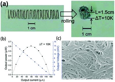 | ||
| Fig. 10 (a) Photograph and (b) output power–current and output voltage–current curves of the TEG with SWCNT/PVDF composite fibers. (c) SEM image of PEI(2wt%)-treated SWCNT/PVDF fibers (50wt%). (Reproduced from ref. 135 with permission from The Royal Society of Chemistry.). | ||
In the past decade, the thermoelectric properties of only a few organic small molecule (OSM) materials have been studied in detail, such as porphyrin,136 bis-(ethylenedithio)tetrathiafulvalene (BEDT-TTF),137 2-[4,5-(1,2-cyclohexylenedithio)-1,3-dithiol-2-ylidene]-5-[4,5-bis(methylthio)-1,3-dithiol-2-ylidene]-1,3,4,6-tetrathiapentalene (ChTM-TTP),138 thiophene-diketopyrrolopyrrole-based quinoidal small molecules (TDPPQ),139 (dipyrrolo[3,4-c]pyrrole-1,4-diylidene)bis(thieno[3,2-b]thiophene) (DPPTT),140 and bis(ethylenedithio)tetrathiafulvalene (BEDT-TTF).141 They have lower power factors (maximum power factor 100–200 μW m−1 K−2)139,140 compared with inorganic thermoelectric compounds. Therefore, in addition to the superlattice structures discussed in section 2.3, OSM materials are often chosen as fillers or coatings of thermoelectric composites in which carbon nanotubes are an additional phase.136,142 Yao et al. fabricated copper phthalocyanine (CuPc)/single-walled carbon nanotube (SWCNT) p-type composites by high energy ball milling and cold pressing.143 A large number of CuPc-SWCNT nano-interfaces in the composites lead to strong donor–acceptor and π–π conjugation interactions and endow CuPc with highly ordered face-on packing, which leads to an increase of the carrier concentration and carrier mobility. After optimization, CuPc/SWCNT composites showed a maximum power factor of about 70.1 μW (m K2)−1.
Wang et al. prepared a series of OSMs and SWCNTs composites by a drop-casting process and solution-phase or vapour-phase doping,144,145 as shown in Fig. 11a. The interfacial doping of the thermoelectric composite films with a vacuum-deposited organic acceptor, 7,7,8,8-tetracyanoquinodimethane (TCNQ), leads to the formation of charge-transfer complex crystals at the interface, resulting in increased carrier mobility. As shown in Fig. 11b and c, less interruption to the lattice structure and controlled charge transfer between these phases leads to a higher power factor of 284 μW (m K2)−1 at room temperature.145
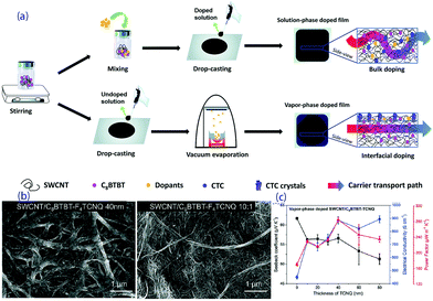 | ||
| Fig. 11 (a) Fabrication processes of the composite films by bulk doping or interfacial doping, (b) SEM pictures of an SWCNT/C8BTBT-F4TCNQ film obtained with a vapor-phase process and an SWCNT/C8BTBT-F4TCNQ film obtained with a solution-phase process, and (c) the transport properties of vapor-phase doped SWCNT/C8BTBT-TCNQ with different thicknesses of TCNQ.145 | ||
5.2 Graphene-based composites
Although pure organic thermoelectric materials have good thermoelectric properties, their properties are still far poorer than those of inorganic thermoelectric materials. If graphene with high electrical and mechanical properties is introduced into an organic thermoelectric material, it is expected that the low thermal conductivity of the organic thermoelectric material will combine with the high electrical conductivity of graphene to afford better performance. Also, when graphene is uniformly dispersed in the polymer matrix, it has a higher ability to enhance the thermoelectric properties of composites than carbon nanotubes because graphene has a larger surface area and stronger π–π interactions with the same weight. According to the literature,146–148 when graphite is uniformly distributed in the polymer matrix, graphene can increase the interface area 2–10 times more than the equivalent mass of carbon nanotubes; a 10-fold increase in ZT value can be observed after the addition of 2 to 3 wt% of graphene into the PEDOT:PSS matrix, which is much higher than that of the carbon nanotube-based composite material. Graphene is also used as a template in a polymer matrix for the purpose of stretching a polymer chain (such as PAIN) to enhance its carrier mobility and increase its conductivity without reducing its thermal power. Xiang et al.118 synthesized a paper-like GNP-PAIN complex by in situ polymerization of single molecule aniline in the presence of GNP, and its ZT value shows two orders of magnitude of improvement compared to pure PAIN and GNP. Recently, fullerene has also been used to enhance the performance of graphene-based composite thermoelectric materials. In this system, rGO is non-covalently functionalized by fullerene and then incorporated into the PEDOT:PSS matrix. The conductivity can be increased by graphene, while fullerene can increase the Seebeck coefficient and does not greatly improve the thermal conductivity. Due to this synergistic effect, the thermoelectric figure can reach 0.067, which is an order of magnitude higher than that of any single component-filled thermoelectric polymer.119 Zhang et al.117 successfully synthesized rGO/F-C60 nanohybrids using a lithiation method, in which rGO is non-covalently functionalized by F-C60 so that F-C60 can regulate the HOMO and work function of rGO. The prepared rGO/F-C60 nanohybrids were incorporated into the organic conductive polymer PEDOT:PSS, and low-energy carriers were scattered by the Schottky barrier at the interface between rGO/F-C60 and PEDOT:PSS. When the doping content is 2.5% and the interface barrier is 0.7 eV, the highest power factor of 83.2 μW (m K2)−1 is acquired, which is 19 times better than that of pure PEDOT:PSS. On the other hand, because the F-C60 nanoparticles on the surface of rGO can effectively scatter phonons and hinder the heat transport, the thermoelectric figure of merit is finally 0.1, which is the highest thermoelectric figure of merit of graphene-based composite thermoelectric materials that have been reported to date.Park et al. introduced the PEDOT:PSS conducting polymer via spin coating to cover the defects on the graphene film surface and fabricate a graphene/PEDOT:PSS transparent composite film. As shown in Fig. 12, RTCVD graphene was transferred onto a PET substrate and was irradiated with ultraviolet light. Then, PEDOT:PSS doped with 5 wt% DMSO was dropped onto the RTCVD graphene film via spin coating. The residual solvents were evaporated via an annealing process at 150 °C for 2 min. The sheet resistance of the composite film had a 48% decrease compared with that of the graphene film. Although the Seebeck coefficient decreased slightly, higher ZT could be obtained with lower thermal conductivity.149 More interestingly, the PEDOT:PSS thin film reduced the surface defects and improved the bending stability of the film. Due to the constrained distortion of graphene during the bending stress, the thermoelectric performance remained stable after 1000 cycles.
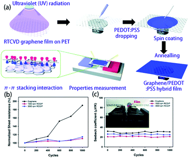 | ||
| Fig. 12 (a) Schematics of the hybridization process of RTCVD graphene and PEDOT:PSS and the π–π stacking interaction interface between graphene and the PEDOT:PSS chains. (b) Plots of the sheet resistance and (c) Seebeck coefficient versus the bending cycle number of the graphene film and RCG/P hybrid films. (Reproduced from ref. 149 with permission from AIP.). | ||
6. Other inorganic-based composites
In addition to chalcogenide composites and carbon-based composites for the preparation of flexible thermoelectric films, other inorganic fillers, such as oxides and nickel–cobalt fibers, are used to fabricate flexible thermoelectric elements.6.1 Oxides
Andrei et al. prepared a thermoelectric paste using a mixture of graphite, cuprous oxide and polychlorotrifluoroethylene.150 By adjusting the ratio between graphite and cuprous oxide, the Seebeck coefficient of the paste was varied between 10 and 600 μV K−1 and the conductivity was between 10−4 and 102 S m−1. The maximum power factor of the composite could reach 7 × 10⁻⁵ μW (m K2)−1.Geppert et al.151 prepared a Ca3Co4O9/CuO/Ag-based ceramic composite to make a p-type thermoelectric leg. Cu–Ni–Mn alloy was used as an n-type leg in the module. The flexible module (P-type leg with 5 mol% Ag and Cu addition) showed a maximum output power of 60 μW.
Xin et al.152 prepared flexible polypyrrole (PPy) nanotube/reduced graphene oxide (rGO) hybrid films via vacuum filtration. The unique network in the PPy nanotube/rGO hybrid films can destroy the aggregation of the nanosheets and supply effective channels to conduct the electrons. The power factor of PPy/rGO hybrid film was more than 130 times larger than that of the pure PPy nanotube film. In contrast with other oxide-based composites, the films showed excellent performance stability after repeated mechanical bending.
6.2 Metal nanowires
Chen et al. used a magnetic field to align Co nanowires within a poly(vinylidene fluoride) matrix during the process, which significantly decreased the electrical resistivity in comparison to the nanocomposites with random orientation. The maximum power factor of the Co/PVDF composites can reach 500 μW m−1 K−2 at 45 °C. The flexible and planar thermoelectric module were fabricated via pairing these n-type legs with p-type PEDOT:PSS legs, and the maximum output voltage and power were 26.4 mV and 5.2 μW, respectively, at ΔT = 50 K.1537. Hybrid thermoelectric devices and applications
With the continuous improvement of the fabrication procedure and performance of flexible thermoelectric materials, research on their practical application in devices has attracted increasing attention. The devices can collect heat from the environment for self-energy supply and effectively reduce practical application costs. Combined with their inherent flexibility, hybrid thermoelectric materials and their devices have great potential applications in wearable devices.64,154–156 Additionally, some groups have developed different types of actual devices.7.1 Thermoelectric generators (TEGs)
TEGs based on the Seebeck effect are the most basic and widely applied due to their low power consumption and self-powered, maintenance-free operation.129,157,158 Flexible TEGs are especially suitable for obtaining thermal energy from heat source surfaces with complex shapes, and they have many potential applications in wearable devices and the internet of things due to their advantages of easy bending, low cost and light weight; thus, they have received extensive attention from the public. Many groups focus on the optimisation of the device fabrication, structure optimization and possible applications.Park et al. first prepared PEDOT films on a thin polyethyleneterephthalate (PET) film with solution casting polymerization and formed the foils into roll-type legs, which were easily connected to electrodes. These flexible p-type legs were integrated with rigid n-type Bi2Te3 legs to assemble a rigid-flexible TEG with 36 couples, as shown in Fig. 13.159 Due to this combination of rigid and flexible parts, the generator can move like skeletal fingers. The power output under ΔT = 8 K is about 120 nW under a resistance of 3.0 kΩ, and the output voltage was 10.6 mV, which was generated constantly and steadily from human body heat.
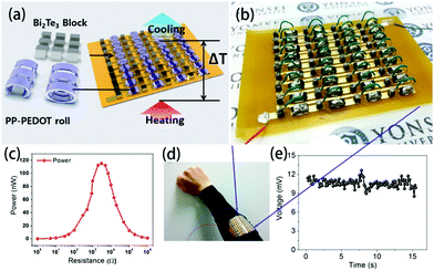 | ||
| Fig. 13 (a) Schematic of the module structure based on PP-PEDOT rolls and Bi2Te3 blocks, (b and d) photographic images of an RF-TEG consisting of 36 thermocouples composed of PP-PEDOT rolls and Bi2Te3 blocks, (c) the maximum power at ΔT ∼ 8 K as a function of load resistance, and (e) the output voltage of the module fabricated as a wearable energy harvester. The output voltage of the 36-couple RF-TEG was determined to be 10.6 mV, which was generated constantly and steadily from human body heat. (Reproduced from ref. 159 with permission from AIP.). | ||
Takashiri et al. proposed and fabricated flexible thin-film TEGs via electrodeposition and transfer processes at a low manufacturing cost. N-type Bi2Te3 films and p-type Sb2Te3 films were chosen as p and n legs, respectively. Thin stainless-steel foil was selected as a substrate material. After electrodeposition was complete, the films were fixed on a glass plate using epoxy resin, subsequently removed from the stainless-steel substrate, and then assembled into different modules, as shown in Fig. 14. The generator had a maximum power of 10.4 nW with a temperature difference of 60 K. The performance of the thin-film generators can be improved by decreasing the number of micro-cracks and achieving tight connections between different legs using silver paste.73
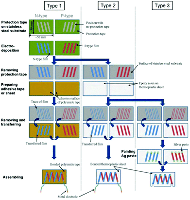 | ||
| Fig. 14 Schematic process, flow diagram and photographs of the three types of flexible thin-film TEGs.73 | ||
An et al.129 chose to directly spin carbon nanotubes with different treatments as p- and n-type legs and fabricate planar and vertical thermoelectric modules. The free-standing webs of carbon nanotubes were attached to a flexible polyethylene terephthalate (PET) substrate to create an electrical connection, in which each source was electrically connected by Ag paste through a dispensing process. The 20 n-type or p-type active legs, with widths of 1.5 mm, lengths of 12 mm, and thicknesses of 20 mm, were cross-connected from the “cold side” of one leg to the “hot side” of the adjacent leg to obtain single-junction TE modules (Fig. 15). The maximum power output of the p–n junction TE module increased with increasing temperature gradient, approaching 7.1 mW at ΔT = 20 K. A vertical TE module was fabricated by stacking 20 layers of planar 10 p–n TE couples serially and sandwiching the layers between two ceramic plates to deliver heat homogenously. The voltage and current varied depending on the temperature difference, and a maximum power output of 123 mW was achieved at ΔT = 20 K.
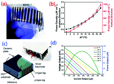 | ||
| Fig. 15 Fabrication of planar (a) and vertical (c) thermoelectric modules and power densities as a function of temperature gradient for the (b) planar and (d) vertical modules. (Reproduced from ref. 129 with permission from The Royal Society of Chemistry.). | ||
Nishino et al. used Ni-based and Bi2Te3-based thermoelectric materials to develop a flexible TEG.160 Thermoelectric materials were first sputter-deposited on a polyimide flexible substrate. Then, the Bi2Te3-based materials were annealed at 300 °C to improve their performance, while the Ni-based materials needed no further annealing. A flexible printed film with copper layers was then prepared as the heat path film. The films were integrated with the heat path film via an epoxy adhesive and vacuum lamination to obtain the final TEG, which reached a power density of 0.1 μW (K cm2)−1. Although the power density was not high, the heat path structure of this device could realize the transition from a longitudinal temperature difference to a lateral temperature difference.
Zhao et al. developed a prototype of a transparent paper-based TEG and supplemented it with a resin impregnation method.161 N-Type and P-type pastes, which contained BiSbTe alloy powders, glycerin, ethylene glycol, and polyvinylpyrrolidone, were alternately dropped onto the PTFE flexible substrate and then covered with another paper substrate. The pastes penetrated into the paper substrate with very slight pressure and were connected by conductive silver pastes. Finally, epoxy resin was placed inside to obtain a prototype of a transparent paper-based TEG. After 1000 bending cycles, this transparent paper-based TEG could maintain a voltage of about 8.3 mV and an output power of about 10 nW at ΔT = 35 K. Huu et al. proposed a lateral Y-type architecture instead of the traditional vertical π-type architecture. The electrochemical deposition process was used to fabricate a durable flexible TEG,72 and an output power density of 3 μW cm−2 was obtained at ΔT = 22 K.
7.2 Environmental sensor
Sensors can continuously monitor various environmental or industrial elements and play key roles in modern industry and life. In recent years, with the development of many polymer-based thermoelectric composites, flexible thermoelectric devices can not only be self-energized by thermal energy in the environment but can also monitor changes in the environment, such as human body temperature and pressure.162–167Seo et al.165 developed a dual output sensor based on the structural design of thermoelectric materials (SDTM) which was designed to monitor fluid temperature and dynamics. When the temperature of the working fluid is 312 K (ΔT = 14 K), the power density is 42 μW cm−2. This power can enable the sensor to analyze real-time signals and transmit the data to an external platform.
Based on the thermoelectric effects of graphene, Hou et al.166 demonstrated a simple flexible human touch sensor. The sensor is self-powered from its own thermoelectric conversion effect and can sense heating or cooling of the local area and pressure to perceive a person's touch position, which suggests unique potential application value in the development of electronic skin.
7.3 Refrigeration applications
Hou et al.52 developed a very simple method for preparing a flexible TE cooling device. Bi0.5Sb1.5Te3 was the thermoelectric component and epoxy resin was the binder; they were brushed on a polyimide flexible substrate and then hot-pressed in a curing process. An Al/Cu/Ni multilayer film electrode was deposited on the polyimide substrate by vacuum evaporation. The prototype of the refrigeration unit was 60 mm long and 260 μm thick. The hot and cold ends of the device prototype could establish a stable temperature difference of 6.2 K at a current of 0.06 A. Meanwhile, when the bending radius was between 20 mm and 90 mm, the resistance of the device remained almost unchanged after 2500 bending recovery cycles. Additionally, Lu et al.57 and Wu et al.168 fabricated a film refrigeration device through inkjet printing technology and a simple brushing technique, respectively. Both could achieve a stable temperature difference of about 3.2 K.8. Conclusions and outlook
The key advantages of organic/inorganic thermoelectric composites are their flexibility and easy fabrication. Due to both points, these composites are uniquely competitive in the application of collecting energy from waste heat or the environment to supply electricity to wireless communication units, physical sensors and wearable electronics, which create low-grade waste heat. However, this technology is still in a primitive stage and will face many challenges in the future. These include:(1) Telluride is a key inorganic material used in thermoelectric composites which has excellent ZT values (about 1 or higher). However, Te is a rare earth element which only accounts for 0.005 ppm of the crustal content. Meanwhile, this element is also toxic and harmful to the nerves, liver, gastrointestinal tract and reproductive system of human beings. If Te is used in MEMS circuits or sensors, it is difficult to recycle it; therefore, the application and development of thermoelectric modules is unsustainable and pollutes the environment. Thus, it is urgent to seek new inorganic fillers with excellent performance and low cost.
(2) Due to the non-uniform particle size distributions, agglomeration and interfacial problems of inorganic materials, their thermoelectric performance is very sensitive to the fabrication process, which weakens the actual composite mechanism. Therefore, it may be meaningless to improve the properties of the matrix and fillers. In order to correctly picture the possible physical mechanisms, it is necessary to develop better chemical processes to obtain original powders and inks with high quality.
(3) As stated in Section 2, “Scientific mechanisms in organic/inorganic thermoelectric composites”, percolation theory, grain boundaries and interface effects, and superlattice effects/energy filter effects are used to enhance the performance of organic/inorganic thermoelectric composites. However, markedly different results have been obtained for similar composites by different scientific groups worldwide. After removing the measurement error, these differences arise from the intrinsic properties of the matrix and fillers, which are somewhat sensitive to the synthesis parameters. Meanwhile, dirt on the interfaces between these phases and the environment also deteriorates the transport properties of composite materials. Scientists should not focus only on physical properties while ignoring these technical details.
(4) Due to very weak electric signals during the measurement, the Seebeck coefficient values are somewhat unreliable and inaccurate. As a result, the reported thermoelectric properties and power densities of the devices are different, with values ranging from several μW (m K2)−1 to a thousand μW (m K2)−1. Meanwhile, the thermal diffusivity model to evaluate the thermal conductivity of films and fibers is very poor, unlike that of their thermoelectric bulks. Combined with the anisotropy of 2D or layered structured films, the ZT values of these films must therefore be double-checked in future.
(5) With the rapid development of integrated circuits, lower energy consumption is needed for devices. In view of their foreseeable commercial applications, it is more urgent to develop large-scale fabrication techniques to produce films of high quality and high efficiency (such as ink printing and screen printing) than to improve the performance of the materials.
Conflicts of interest
There are no conflicts to declare.Acknowledgements
This work was supported by the National Natural Science Foundation of China (NSFC No. 51772019, 51572098, 51632006), National Key Research and Development Plan of China (2018YFB1503100), and NSFC-Royal Society joint project (5171101927).Notes and references
- D. S. Ayou and V. Eveloy, Energy Convers. Manage., 2020, 213, 112790 CrossRef CAS.
- A. P. Straub, N. Y. Yip, S. H. Lin, J. Lee and M. Elimelech, Nat. Energy, 2016, 1, 16090, DOI:10.1038/nenergy.2016.90.
- Y. Ammar, S. Joyce, R. Norman, Y. D. Wang and A. P. Roskilly, Appl. Energy, 2012, 89, 3–20 CrossRef.
- I. Chowdhury, R. Prasher, K. Lofgreen, G. Chrysler, S. Narasimhan, R. Mahajan, D. Koester, R. Alley and R. Venkatasubramanian, Nat. Nanotechnol., 2009, 4, 235–238 CrossRef CAS PubMed.
- J. Xin, Y. Tang, Y. Liu, X. Zhao, H. Pan and T. Zhu, npj Quant. Mater., 2018, 3, 9 CrossRef.
- M. Jin, Z. Chen, X. Tan, H. Shao, G. Liu, H. Hu, J. Xu, B. Yu, H. Shen, J. Xu, H. Jiang, Y. Pei and J. Jiang, ACS Energy Lett., 2018, 3, 689–694 CrossRef CAS.
- Q. Jiang, H. Hu, J. Yang, J. Xin, S. Li, G. Viola and H. Yan, ACS Appl. Mater. Interfaces, 2020, 12, 23102–23109 CrossRef CAS.
- S. Duan, N. Man, J. Xu, Q. Wu, G.-q. Liu, X. Tan, H. Shao, K. Guo, X. Yang and J. Jiang, J. Mater. Chem. A, 2019, 7, 9241–9246 RSC.
- L. Mao, Y. Yin, Q. Zhang, G.-Q. Liu, H. Wang, Z. Guo, H. Hu, Y. Xiao, X. Tan and J. Jiang, Energy Environ. Sci., 2020, 13, 616–621 RSC.
- S. Li, J. Yang, Y. Liu, J. Xin, S. Li, Q. Long and Q. Jiang, Adv. Appl. Ceram., 2020, 119, 107–113 CrossRef CAS.
- G. M. Chen, W. Xu and D. B. Zhu, J. Mater. Chem. C, 2017, 5, 4350–4360 RSC.
- C. W. Nan, Y. Shen and J. Ma, in Annual Review Of Materials Research, ed. D. R. Clarke, M. Ruhle and F. Zok, 2010, vol. 40, pp. 131–151 Search PubMed.
- N. Rolland, J. F. Franco-Gonzalez, R. Volpi, M. Linares and I. V. Zozoulenko, Phys. Rev. Mater., 2018, 2, 045605 CrossRef CAS.
- J. Liu, L. Qiu, R. Alessandri, X. Qiu, G. Portale, J. Dong, W. Talsma, G. Ye, A. A. Sengrian, P. C. T. Souza, M. A. Loi, R. C. Chiechi, S. J. Marrink, J. C. Hummelen and L. J. A. Koster, Adv. Mater., 2018, 30, 1704630 CrossRef PubMed.
- I. Petsagkourakis, E. Pavlopoulou, E. Cloutet, Y. F. Chen, X. Liu, M. Fahlman, M. Berggren, X. Crispin, S. Dilhaire, G. Fleury and G. Hadziioannou, Org. Electron., 2018, 52, 335–341 CrossRef CAS.
- Q. Jiang, H. Yan, J. Khaliq, Y. Shen, K. Simpson and M. J. Reece, J. Mater. Chem. A, 2014, 2, 9486–9489 RSC.
- A. Gharleghi, Y. Liu, M. Zhou, J. He, T. M. Tritt and C.-J. Liu, J. Mater. Chem. A, 2016, 4, 13874–13880 RSC.
- L. Horta Romarís, M. V. González Rodríguez, B. Huang, P. Costa, A. Lasagabáster Latorre, S. Lanceros-Mendez and M. J. Abad López, J. Mater. Chem. C, 2018, 6, 8502–8512 RSC.
- B. Liu, L. Dong, Q. Xi, X. F. Xu, J. Zhou and B. W. Li, Front. Energy, 2018, 12, 72–86 CrossRef.
- B. Shi, L. Dong, M. Li, B. Liu, K. Kim, X. Xu, J. Zhou and J. Liu, Appl. Phys. Lett., 2018, 113, 041902 CrossRef.
- T. Zhu, Y. Liu, C. Fu, J. P. Heremans, J. G. Snyder and X. Zhao, Adv. Mater., 2017, 29, 1605884 CrossRef.
- L.-D. Chen, Z. Xiong and S.-Q. Bai, J. Inorg. Mater., 2010, 25, 561–568 CrossRef CAS.
- T.-R. Wei, Y. Qin, T. Deng, Q. Song, B. Jiang, R. Liu, P. Qiu, X. Shi and L. Chen, Sci. China Mater., 2019, 62, 8–24 CrossRef CAS.
- K. Biswas, J. He, I. D. Blum, C.-I. Wu, T. P. Hogan, D. N. Seidman, V. P. Dravid and M. G. Kanatzidis, Nature, 2012, 489, 414 CrossRef CAS PubMed.
- V. Andrei, K. Bethke, F. Madzharova, S. Beeg, A. Knop-Gericke, J. Kneipp and K. Rademann, Adv. Electron. Mater., 2017, 3, 1600473 CrossRef.
- D. Ni, Y. Chen, H. Song, C. Liu, X. Yang and K. Cai, J. Mater. Chem. A, 2019, 7, 1323–1333 RSC.
- Y. Du, K. F. Cai, S. Chen, P. Cizek and T. Lin, ACS Appl. Mater. Interfaces, 2014, 6, 5735–5743 CrossRef CAS.
- L. D. Hicks and M. S. Dresselhaus, Phys. Rev. B: Condens. Matter Mater. Phys., 1993, 47, 12727–12731 CrossRef CAS PubMed.
- R. Venkatasubramanian, E. Siivola, T. Colpitts and B. O'Quinn, Nature, 2001, 413, 597–602 CrossRef CAS PubMed.
- A. Giri, J. P. Niemela, C. J. Szwejkowski, M. Karppinen and P. E. Hopkins, Phys. Rev. B, 2016, 93, 024201 CrossRef.
- M. G. Kanatzidis, R. Bissessur, D. C. DeGroot, J. L. Schindler and C. R. Kannewurf, Chem. Mater., 1993, 5, 595–596 CrossRef CAS.
- C. Wan, X. Gu, F. Dang, T. Itoh, Y. Wang, H. Sasaki, M. Kondo, K. Koga, K. Yabuki, G. J. Snyder, R. Yang and K. Koumoto, Nat. Mater., 2015, 14, 622–627 CrossRef CAS PubMed.
- C. Wan, R. Tian, M. Kondou, R. Yang, P. Zong and K. Koumoto, Nat. Commun., 2017, 8, 1024 CrossRef PubMed.
- D. Jariwala, T. J. Marks and M. C. Hersam, Nat. Mater., 2017, 16, 170–181 CrossRef CAS PubMed.
- K. S. Novoselov, A. Mishchenko, A. Carvalho and A. H. Castro Neto, Science, 2016, 353, aac9439 CrossRef CAS PubMed.
- C. Wang, Q. He, U. Halim, Y. Liu, E. Zhu, Z. Lin, H. Xiao, X. Duan, Z. Feng, R. Cheng, N. Weiss, G. Ye, Y.-C. Huang, H. Wu, H.-C. Cheng, I. Shakir, L. Liao, X. Chen, W. A. Goddard, Y. Huang and X. Duan, Nature, 2018, 555, 231–236 CrossRef CAS PubMed.
- X. Wang, M. Zebarjadi and K. Esfarjani, Nanoscale, 2016, 8, 14695–14704 RSC.
- Y. Lu, Y. Qiu, K. Cai, Y. Ding, M. Wang, C. Jiang, Q. Yao, C. Huang, L. Chen and J. He, Energy Environ. Sci., 2020, 13, 1240–1249 RSC.
- S. Cavaliere, S. Subianto, I. Savych, D. J. Jones and J. Roziere, Energy Environ. Sci., 2011, 4, 4761–4785 RSC.
- B. Ding, M. R. Wang, X. F. Wang, J. Y. Yu and G. Sun, Mater. Today, 2010, 13, 16–27 CrossRef CAS.
- N. Dalton, R. P. Lynch, M. N. Collins and M. Culebras, Int. J. Biol. Macromol., 2019, 121, 472–479 CrossRef CAS PubMed.
- Y. A. Shah, M. J. Iqbal, K. Rasool, A. U. R. Makhdoom, Y. Iqbal, A. Ullah and M. Habib, Appl. Phys. A: Mater. Sci. Process., 2020, 126, 376 CrossRef CAS.
- A. C. Marques, D. Miglietta, G. Gaspar, A. C. Baptista, A. Gaspar, P. Perdigao, I. Soares, C. Bianchi, D. Sousa, B. M. M. Faustino, V. S. Amaral, T. Santos, A. P. Goncalves, R. C. da Silva, F. Giorgis and I. Ferreira, Mater. Renewable Sustainable Energy, 2019, 8, 21 CrossRef CAS PubMed.
- M. Zhang, S.-D. Park, J. Kim, M. Nalbandian, S. Kim, Y. Choa, J. Lim and N. V. Myung, Front. Chem., 2018, 6, 436 CrossRef CAS PubMed.
- Q. Wang, Q. Yao, J. Chang and L. D. Chen, J. Mater. Chem., 2012, 22, 17612–17618 RSC.
- J. A. Lee, A. E. Aliev, J. S. Bykova, M. J. de Andrade, D. Kim, H. J. Sim, X. Lepro, A. A. Zakhidov, J. B. Lee, G. M. Spinks, S. Roth, S. J. Kim and R. H. Baughman, Adv. Mater., 2016, 28, 5038–5044 CrossRef CAS PubMed.
- Q. Jiang, H. Yan, Y. Lin, Y. Shen, J. Yang and M. J. Reece, J. Mater. Chem. A, 2020, 8, 10909–10916 RSC.
- M. S. Dresselhaus, G. Chen, M. Y. Tang, R. Yang, H. Lee, D. Wang, Z. Ren, J.-P. Fleurial and P. Gogna, Adv. Mater., 2007, 19, 1043–1053 CrossRef CAS.
- H. Wang, C. Xiong, G. Luo, H. Hu, B. Yu, H. Shao, X. Tan, J. Xu, G. Liu, J. G. Noudem and J. Jiang, Energy Technol., 2019, 7, 1900814 CrossRef CAS.
- C. Tan, X. Tan, B. Yu, G.-Q. Liu, H. Wang, G. Luo, J. Xu, Q. Wu, B. Liang and J. Jiang, ACS Appl. Energy Mater., 2019, 2, 6714–6719 CrossRef CAS.
- J. Kim, O. H. Kwon, Y. H. Kang, K. S. Jang, S. Y. Cho and Y. Yoo, Compos. Sci. Technol., 2017, 153, 32–39 CrossRef CAS.
- W. Hou, X. Nie, W. Zhao, H. Zhou, X. Mu, W. Zhu and Q. Zhang, Nano Energy, 2018, 50, 766–776 CrossRef CAS.
- Q. Jiang, F. Liu, H. Yan, H. Ning, Z. Libor, Q. Zhang, M. Cain and M. J. Reece, J. Am. Ceram. Soc., 2011, 94, 2311–2314 CrossRef CAS.
- Q. Jiang, H. Ning, Q. Zhang, M. Cain, M. J. Reece and H. Yan, J. Mater. Chem. C, 2013, 1, 5628–5631 RSC.
- Q. Jiang, J. Yang, J. Xin, Z. Zhou, D. Zhang and H. Yan, J. Alloys Compd., 2017, 694, 864–868 CrossRef CAS.
- Z.-H. Ge, Y. Chang, F. Li, J. Luo and P. Fan, Chem. Commun., 2018, 54, 2429–2431 RSC.
- K. Wei and G. S. Nolas, Scr. Mater., 2018, 150, 70–73 CrossRef CAS.
- D. B. Kuang, A. W. Xu, Y. P. Fang, H. Q. Liu, C. Frommen and D. Fenske, Adv. Mater., 2003, 15, 1747–1750 CrossRef CAS.
- M. He, J. Ge, Z. Lin, X. Feng, X. Wang, H. Lu, Y. Yang and F. Qiu, Energy Environ. Sci., 2012, 5, 8351–8358 RSC.
- J. Gao, C. Liu, L. Miao, X. Wang, Y. Peng and Y. Chen, RSC Adv., 2016, 6, 31580–31587 RSC.
- Z. Lin, C. Hollar, J. S. Kang, A. Yin, Y. Wang, H.-Y. Shiu, Y. Huang, Y. Hu, Y. Zhang and X. Duan, Adv. Mater., 2017, 29 CAS.
- H. Choi, Y. J. Kim, C. S. Kim, H. M. Yang, M.-W. Oh and B. J. Cho, Nano Energy, 2018, 46, 39–44 CrossRef CAS.
- T. Varghese, C. Hollar, J. Richardson, N. Kempf, C. Han, P. Gamarachchi, D. Estrada, R. J. Mehta and Y. Zhang, Sci. Rep., 2016, 6, 33135 CrossRef CAS PubMed.
- S. J. Kim, J. H. We and B. J. Cho, Energy Environ. Sci., 2014, 7, 1959–1965 RSC.
- Z. Yuan, X. Tang, Z. Xu, J. Li, W. Chen, K. Liu, Y. Liu and Z. Zhang, Appl. Energy, 2018, 225, 746–754 CrossRef CAS.
- H. Choi, S. J. Kim, Y. Kim, J. H. We, M.-W. Oh and B. J. Cho, J. Mater. Chem. C, 2017, 5, 8559–8565 RSC.
- C. Han, G. Tan, T. Varghese, M. G. Kanatzidis and Y. Zhang, ACS Energy Lett., 2018, 3, 818–822 CrossRef CAS.
- Y. Wang, S. M. Zhang and Y. Deng, J. Mater. Chem. A, 2016, 4, 3554–3559 RSC.
- H. S. Cho, H. X. Deng, K. Miyasaka, Z. Y. Dong, M. Cho, A. V. Neimark, J. K. Kang, O. M. Yaghi and O. Terasaki, Nature, 2015, 527, 503–507 CrossRef.
- J. P. Niemela, A. J. Karttunen and M. Karppinen, J. Mater. Chem. C, 2015, 3, 10349–10361 RSC.
- N. H. Trung, N. Van Toan and T. Ono, J. Micromech. Microeng., 2017, 27, 125006 CrossRef.
- T. Nguyen Huu, T. Nguyen Van and O. Takahito, Appl. Energy, 2018, 210, 467–476 CrossRef.
- H. Yamamuro, N. Hatsuta, M. Wachi, Y. Takei and M. Takashiri, Coatings, 2018, 8 Search PubMed.
- M. Culebras, A. M. Igual-Muñoz, C. Rodríguez-Fernández, M. I. Gómez-Gómez, C. Gómez and A. Cantarero, ACS Appl. Mater. Interfaces, 2017, 9, 20826–20832 CrossRef CAS PubMed.
- S. M. George, Chem. Rev., 2010, 110, 111–131 CrossRef CAS PubMed.
- S. M. George, B. Yoon and A. A. Dameron, Acc. Chem. Res., 2009, 42, 498–508 CrossRef CAS PubMed.
- S. P. Lonkar, V. V. Pillai and S. M. Alhassan, Sci. Rep., 2018, 8, 13401 CrossRef PubMed.
- J. Cho, J. Park and J. An, J. Eur. Ceram. Soc., 2017, 37, 3131–3136 CrossRef CAS.
- T. Sarnet, T. Hatanpää, M. Vehkamäki, T. Flyktman, J. Ahopelto, K. Mizohata, M. Ritala and M. Leskelä, J. Mater. Chem. C, 2015, 3, 4820–4828 RSC.
- T. Tynell, A. Giri, J. Gaskins, P. E. Hopkins, P. Mele, K. Miyazaki and M. Karppinen, J. Mater. Chem. A, 2014, 2, 12150–12152 RSC.
- H. S. Mann, B. N. Lang, Y. Schwab, J.-P. Niemelä, M. Karppinen and G. Scarel, J. Vac. Sci. Technol., A, 2014, 33, 01A124 CrossRef.
- L. Zheng, X. Cheng, D. Cao, Q. Wang, Z. Wang, C. Xia, L. Shen, Y. Yu and D. Shen, RSC Adv., 2015, 5, 40007–40011 RSC.
- S. Lee, J.-H. Han, S.-H. Lee, G.-H. Baek and J.-S. Park, JOM, 2019, 71, 197–211 CrossRef.
- K. L. Jarvis and P. J. Evans, Thin Solid Films, 2017, 624, 111–135 CrossRef CAS.
- J. Sheng, K.-L. Han, T. Hong, W.-H. Choi and J.-S. Park, J. Semicond., 2018, 39, 011008 CrossRef.
- G. K. Hyde, K. J. Park, S. M. Stewart, J. P. Hinestroza and G. N. Parsons, Langmuir, 2007, 23, 9844–9849 CrossRef CAS PubMed.
- J. P. Niemelä, A. J. Karttunen and M. Karppinen, J. Mater. Chem. C, 2015, 3, 10349–10361 RSC.
- A. J. Karttunen, L. Sarnes, R. Townsend, J. Mikkonen and M. Karppinen, Adv. Electron. Mater., 2017, 3, 1600459 CrossRef.
- L. L. Shen, P. P. Liu, C. C. Liu, Q. L. Jiang, J. K. Xu, X. M. Duan, Y. K. Du and F. X. Jiang, ACS Appl. Polym. Mater., 2020, 2, 376–384 CrossRef CAS.
- G. D. Cummins and M. P. Yves, Circuit World, 2012, 38, 193–213 CrossRef CAS.
- M. Orrill and S. LeBlanc, J. Appl. Polym. Sci., 2017, 134, 44256 CrossRef.
- Z. Yin, Y. Huang, N. Bu, X. Wang and Y. Xiong, Chin. Sci. Bull., 2010, 55, 3383–3407 CrossRef.
- E. Tekin, P. J. Smith and U. S. Schubert, Soft Matter, 2008, 4, 703–713 RSC.
- D. Kim, S. Jeong, B. K. Park and J. Moon, Appl. Phys. Lett., 2006, 89, 264101 CrossRef.
- M. Kuang, L. Wang and Y. Song, Adv. Mater., 2014, 26, 6950–6958 CrossRef CAS PubMed.
- K. T. Park, J. Choi, B. Lee, Y. Ko, K. Jo, Y. M. Lee, J. A. Lim, C. R. Park and H. Kim, J. Mater. Chem. A, 2018, 6, 19727–19734 RSC.
- T. Juntunen, H. Jussila, M. Ruoho, S. Liu, G. Hu, T. Albrow-Owen, L. W. T. Ng, R. C. T. Howe, T. Hasan, Z. Sun and I. Tittonen, Adv. Funct. Mater., 2018, 28, 1800480 CrossRef.
- S. Horike, T. Fukushima, T. Saito, T. Kuchimura, Y. Koshiba, M. Morimoto and K. Ishida, Mol. Syst. Des. Eng., 2017, 2, 616–623 RSC.
- B. Chen, S. R. Das, W. Zheng, B. Zhu, B. Xu, S. Hong, C. Sun, X. Wang, Y. Wu and J. C. Claussen, Adv. Electron. Mater., 2017, 3, 1600524 CrossRef.
- Z. Lu, M. Layani, X. Zhao, L. P. Tan, T. Sun, S. Fan, Q. Yan, S. Magdassi and H. H. Hng, Small, 2014, 10, 3551–3554 CrossRef CAS PubMed.
- S. Ferhat, C. Domain, J. Vidal, D. Noël, B. Ratier and B. Lucas, Sustainable Energy Fuels, 2018, 2, 199–208 RSC.
- K. Kato, H. Hagino and K. Miyazaki, J. Electron. Mater., 2013, 42, 1313–1318 CrossRef CAS.
- B. Chen, M. Kruse, B. Xu, R. Tutika, W. Zheng, M. D. Bartlett, Y. Wu and J. C. Claussen, Nanoscale, 2019, 11, 5222–5230 RSC.
- M. He, Y. Zhao, B. Wang, Q. Xi, J. Zhou and Z. Liang, Small, 2015, 11, 5889–5894 CrossRef CAS.
- F. Kim, B. Kwon, Y. Eom, J. E. Lee, S. Park, S. Jo, S. H. Park, B.-S. Kim, H. J. Im, M. H. Lee, T. S. Min, K. T. Kim, H. G. Chae, W. P. King and J. S. Son, Nat. Energy, 2018, 3, 301–309 CrossRef CAS.
- J. Wang, H. Li, R. Liu, L. Li, Y.-H. Lin and C.-W. Nan, Compos. Sci. Technol., 2018, 157, 1–9 CrossRef CAS.
- U. Kalsoom, P. N. Nesterenko and B. Paull, RSC Adv., 2016, 6, 60355–60371 RSC.
- S. Qu, Q. Yao, L. Wang, Z. Chen, K. Xu, H. Zeng, W. Shi, T. Zhang, C. Uher and L. Chen, NPG Asia Mater., 2016, 8, e292 CrossRef CAS.
- L. Wang, Z. Zhang, Y. Liu, B. Wang, L. Fang, J. Qiu, K. Zhang and S. Wang, Nat. Commun., 2018, 9, 3817 CrossRef PubMed.
- B. Zhang, J. Sun, H. E. Katz, F. Fang and R. L. Opila, ACS Appl. Mater. Interfaces, 2010, 2, 3170–3178 CrossRef CAS PubMed.
- C. Ou, A. L. Sangle, A. Datta, Q. Jing, T. Busolo, T. Chalklen, V. Narayan and S. Kar-Narayan, ACS Appl. Mater. Interfaces, 2018, 10, 19580–19587 CrossRef CAS PubMed.
- H. Song, C. Liu, H. Zhu, F. Kong, B. Lu, J. Xu, J. Wang and F. Zhao, J. Electron. Mater., 2013, 42, 1268–1274 CrossRef CAS.
- C. Z. Meng, C. H. Liu and S. S. Fan, Adv. Mater., 2010, 22, 535–539 CrossRef CAS PubMed.
- S. Qu, M. Wang, Y. Chen, Q. Yao and L. Chen, RSC Adv., 2018, 8, 33855–33863 RSC.
- Q. Yao, Q. Wang, L. Wang and L. Chen, Energy Environ. Sci., 2014, 7, 3801–3807 RSC.
- C. Yu, K. Choi, L. Yin and J. C. Grunlan, ACS Nano, 2011, 5, 7885–7892 CrossRef CAS PubMed.
- K. Zhang, S. R. Wang, X. Zhang, Y. Zhang, Y. Cui and J. J. Qiu, Nano Energy, 2015, 13, 327–335 CrossRef CAS.
- J. Xiang and L. T. Drzal, Polymer, 2012, 53, 4202–4210 CrossRef CAS.
- K. Zhang, Y. Zhang and S. Wang, Sci. Rep., 2013, 3, 3448 CrossRef PubMed.
- Y. Sun, H. Cheng, S. Gao, Q. Liu, Z. Sun, C. Xiao, C. Wu, S. Wei and Y. Xie, J. Am. Chem. Soc., 2012, 134, 20294–20297 CrossRef CAS.
- Q. Jiang, H. Yan, J. Khaliq, H. Ning, S. Grasso, K. Simpson and M. J. Reece, J. Mater. Chem. A, 2014, 2, 5785–5790 RSC.
- L. Hu, T. Zhu, X. Liu and X. Zhao, Adv. Funct. Mater., 2014, 24, 5211–5218 CrossRef CAS.
- J. H. We, S. J. Kim and B. J. Cho, Energy, 2014, 73, 506–512 CrossRef CAS.
- C. Dun, C. A. Hewitt, H. Huang, J. Xu, C. Zhou, W. Huang, Y. Cui, W. Zhou, Q. Jiang and D. L. Carroll, Nano Energy, 2015, 18, 306–314 CrossRef CAS.
- H. Ju and J. Kim, ACS Nano, 2016, 10, 5730–5739 CrossRef CAS PubMed.
- C. Bounioux, P. Díaz-Chao, M. Campoy-Quiles, M. S. Martín-González, A. R. Goñi, R. Yerushalmi-Rozen and C. Müller, Energy Environ. Sci., 2013, 6, 918–925 RSC.
- W. Lee, C. T. Hong, O. H. Kwon, Y. Yoo, Y. H. Kang, J. Y. Lee, S. Y. Cho and K.-S. Jang, ACS Appl. Mater. Interfaces, 2015, 7, 6550–6556 CrossRef CAS PubMed.
- P. H. Jiang, H. J. Liu, D. D. Fan, L. Cheng, J. Wei, J. Zhang, J. H. Liang and J. Shi, Phys. Chem. Chem. Phys., 2015, 17, 27558–27564 RSC.
- C. J. An, Y. H. Kang, H. Song, Y. Jeong and S. Y. Cho, J. Mater. Chem. A, 2017, 5, 15631–15639 RSC.
- S. Mohammad Mahdi Dadfar, G. Kavoosi and S. Mohammad Ali Dadfar, Polym. Compos., 2014, 35, 1736–1743 CrossRef.
- C. A. Hewitt, A. B. Kaiser, S. Roth, M. Craps, R. Czerw and D. L. Carroll, Nano Lett., 2012, 12, 1307–1310 CrossRef CAS PubMed.
- B. Massoumi, P. Jafarpour, M. Jaymand and A. A. Entezami, Polym. Int., 2015, 64, 689–695 CrossRef CAS.
- W. Lee, Y. H. Kang, J. Y. Lee, K.-S. Jang and S. Y. Cho, RSC Adv., 2016, 6, 53339–53344 RSC.
- M. L. Wu, Y. Chen, L. Zhang, H. Zhan, L. Qiang and J. N. Wang, ACS Appl. Mater. Interfaces, 2016, 8, 8137–8144 CrossRef CAS PubMed.
- J.-Y. Kim, J.-H. Mo, Y. H. Kang, S. Y. Cho and K.-S. Jang, Nanoscale, 2018, 10, 19766–19773 RSC.
- Y. Zhou, X. J. Yin, Y. J. Liu, X. Y. Zhou, T. Wan, S. C. Wang, C. M. Gao and L. Wang, ACS Sustainable Chem. Eng., 2019, 7, 11832–11840 CrossRef CAS.
- M. Golub and A. Graja, J. Phys. D: Appl. Phys., 2003, 36, 3064–3068 CrossRef CAS.
- T. Kawamoto, M. Ashizawa, T. Mori, J. Yamaura, R. Kato, Y. Misaki and K. Tanaka, Bull. Chem. Soc. Jpn., 2002, 75, 435–447 CrossRef CAS.
- D. Z. Huang, C. Wang, Y. Zou, X. X. Shen, Y. P. Zang, H. G. Shen, X. K. Gao, Y. P. Yi, W. Xu, C. A. Di and D. B. Zhu, Angew. Chem., Int. Ed., 2016, 55, 10672–10675 CrossRef CAS PubMed.
- D. Z. Huang, H. Y. Yao, Y. T. Cui, Y. Zou, F. J. Zhang, C. Wang, H. G. Shen, W. L. Jin, J. Zhu, Y. Diao, W. Xu, C. A. Di and D. B. Zhu, J. Am. Chem. Soc., 2017, 139, 13013–13023 CrossRef CAS PubMed.
- Y. Kiyota, T. Kawamoto, H. Mori and T. Mori, J. Mater. Chem. A, 2018, 6, 2004–2010 RSC.
- C. Y. Gao and G. M. Chen, Small, 2018, 14 Search PubMed.
- Y. L. Chen, S. Y. Qu, W. Shi, Q. Yao and L. D. Chen, Carbon, 2020, 159, 471–477 CrossRef CAS.
- X. J. Yin, Y. H. Peng, J. J. Luo, X. Y. Zhou, C. M. Gao, L. Wang and C. L. Yang, J. Mater. Chem. A, 2018, 6, 8323–8330 RSC.
- J. Tan, Z. Chen, D. Wang, S. Qin, X. Xiao, D. Xie, D. Liu and L. Wang, J. Mater. Chem. A, 2019, 7, 24982–24991 RSC.
- H. X. Kong, Curr. Opin. Solid State Mater. Sci., 2013, 17, 31–37 CrossRef CAS.
- S. Nardecchia, D. Carriazo, M. L. Ferrer, M. C. Gutiérrez and F. del Monte, Chem. Soc. Rev., 2013, 42, 794–830 RSC.
- S.-H. Hwang, H. W. Park and Y.-B. Park, Smart Mater. Struct., 2013, 22, 015013 CrossRef.
- C. Park, D. Yoo, S. Im, S. Kim, W. Cho, J. Ryu and J. H. Kim, RSC Adv., 2017, 7, 25237–25243 RSC.
- V. Andrei, K. Bethke and K. Rademann, Phys. Chem. Chem. Phys., 2016, 18, 10700–10707 RSC.
- B. Geppert, A. Brittner, L. Helmich, M. Bittner and A. Feldhoff, J. Electron. Mater., 2017, 46, 2356–2365 CrossRef CAS.
- S. Xin, N. Yang, F. Gao, J. Zhao, L. Li and C. Teng, Mater. Chem. Phys., 2018, 212, 440–445 CrossRef CAS.
- Y. Chen, M. He, J. Tang, G. C. Bazan and Z. Liang, Adv. Electron. Mater., 2018, 4, 1800200 CrossRef.
- J. Y. Oh, J. H. Lee, S. W. Han, S. S. Chae, E. J. Bae, Y. H. Kang, W. J. Choi, S. Y. Cho, J.-O. Lee, H. K. Baik and T. Il Lee, Energy Environ. Sci., 2016, 9, 1696–1705 RSC.
- F. Suarez, A. Nozariasbmarz, D. Vashaee and M. C. Ozturk, Energy Environ. Sci., 2016, 9, 2099–2113 RSC.
- P. Yang, K. Liu, Q. Chen, X. Mo, Y. Zhou, S. Li, G. Feng and J. Zhou, Angew. Chem., Int. Ed., 2016, 55, 12050–12053 CrossRef CAS PubMed.
- J. Choi, K. Cho and S. Kim, Adv. Energy Mater., 2017, 7, 1602138 CrossRef.
- K. Liu, T. Ding, J. Li, Q. Chen, G. Xue, P. Yang, M. Xu, Z. L. Wang and J. Zhou, Adv. Energy Mater., 2018, 8, 1702481 CrossRef.
- T. Park, H. Lim, J. U. Hwang, J. Na, H. Lee and E. Kim, APL Mater., 2017, 5, 074106 CrossRef.
- T. Nishino and T. Suzuki, J. Micromech. Microeng., 2017, 27, 035011 CrossRef.
- X. Zhao, W. Han, C. Zhao, S. Wang, F. Kong, X. Ji, Z. Li and X. Shen, ACS Appl. Mater. Interfaces, 2019, 11, 10301–10309 CrossRef CAS PubMed.
- W. Zhu, Y. Deng and L. Cao, Nano Energy, 2017, 34, 463–471 CrossRef CAS.
- E. M. F. Vieira, J. Figueira, A. L. Pires, J. Grilo, M. F. Silva, A. M. Pereira and L. M. Goncalves, J. Alloys Compd., 2019, 774, 1102–1116 CrossRef CAS.
- P. Zhu, Y. Wang, M. Sheng, Y. Wang, Y. Yu and Y. Deng, J. Mater. Chem. A, 2019, 7, 8258–8267 RSC.
- B. Seo, H. Hwang, S. Kang, Y. Cha and W. Choi, Nano Energy, 2018, 50, 733–743 CrossRef CAS.
- C. Hou, H. Wang, Q. Zhang, Y. Li and M. Zhu, Adv. Mater., 2014, 26, 5018–5024 CrossRef CAS PubMed.
- Y. J. Kim, H. M. Gu, C. S. Kim, H. Choi, G. Lee, S. Kim, K. K. Yi, S. G. Lee and B. J. Cho, Energy, 2018, 162, 526–533 CrossRef CAS.
- H. Wu, X. Liu, P. Wei, H.-Y. Zhou, X. Mu, D.-Q. He, W.-T. Zhu, X.-L. Nie, W.-Y. Zhao and Q.-J. Zhang, J. Electron. Mater., 2017, 46, 2950–2957 CrossRef CAS.
Footnote |
| † Q. Jiang and H. Ye contributed equally. |
| This journal is © The Royal Society of Chemistry 2020 |

