 Open Access Article
Microstructure, properties and applications of Zr-carbide, Zr-nitride and Zr-carbonitride coatings: a review
Anwar
Ul-Hamid

Center for Engineering Research, Research Institute, King Fahd University of Petroleum & Minerals, Dhahran 31261, Saudi Arabia. E-mail: anwar@kfupm.edu.sa
First published on 1st June 2020
Abstract
Zirconium-based coatings have found important uses ranging from functional deposits on carbon fibers, field emitters, nuclear fuel particles, and dental and body implants to protective layers on tool bits, roller contacts, integrated circuits, and components exposed to high temperatures as well as aesthetically pleasing decorative coatings on common household fixtures. These applications are made possible by the remarkable properties of zirconium such as its high temperature ionic conductivity, corrosion resistivity, good wear resistance, elevated fracture toughness, and high hardness and strength. Zirconium has thermal expansion and modulus of elasticity close to those of iron and steel, respectively. This paper presents a review of the microstructure, properties and applications of Zr-carbide, Zr-nitride and Zr-carbonitride hard coatings synthesized using various processing techniques. The discussion presented in this article is deemed to be relevant to hard coatings in general.
1. Introduction
Zirconium carbide is a hard crystalline refractory ceramic material. It has a metallic grey color and an fcc cubic rock salt structure (Fm3m, space group 225). It belongs to the interstitial metal carbide Group IV. Zr atoms are placed at the corners and centers of faces while C atoms occupy the interstitial octahedral sites. ZrC is sub-stoichiometric with C vacancies. The C/Zr ratio varies from 0.65 to 0.98. Strong covalent bonding between Zr and C results in a high melting temperature, i.e. 3530 °C. It has high thermal and electrical conductivity comparable to that of the Zr metal.Zirconium nitride is a hard refractory ceramic material with a light golden color. It has an fcc cubic structure similar to ZrC but with a slightly smaller lattice constant. Both ZrC and ZrN exhibit covalent bonding due to interactions between the 2p state of the C/N and 4d state of Zr, resulting in Zr–C/Zr–N and Zr–Zr bonding, but no C–C or N–N bonding. Both ZrC and ZrN can accommodate non-metal vacancies and their non-stoichiometric formula can be written as ZrC1−x and ZrN1−x, respectively.1
Zirconium carbonitride is a quasi-binary solid solution, which is due to the carbon and nitrogen atoms occupying the octahedral interstitial sites. δ-Zr(C,N)1−x denotes the solid solution carbonitride with a B1 rocksalt structure (Fm3m, space group 225). The other two phases are the hcp α(ZrC,N) and bcc β(ZrC,N). A three phase equilibrium triangle of δ + α + β also exists with a higher nitride composition of the Zr(CxN1−x)y phase.1 Due to the structure and bonding, Zr-based coatings exhibit a range of useful properties such as high hardness, high temperature stability, biocompatibility, and good resistance to wear, erosion, corrosion and oxidation, rendering them suitable candidates for use in tribological, biomedical, corrosion-resistant, nuclear fuel, electrical and decorative applications.
The application of ZrC as a coating on carbon fibers was first reported by Killin et al. in 1975.2 In the same year, tungsten fibers were coated with ZrC using a flow-type quartz reactor by Samoilenko and Pereselentseva.3 ZrC coatings exhibited higher temperature stability compared to the SiC-coated tri-structural isotropic (TRISO) fuel particles.4,5 In 1993, reactive magnetron sputtered ZrC coatings with high concentrations of carbon were reported to exhibit hardness values as high as 5000 HV.6 Vacuum plasma sprayed coatings exhibited 1600 HV microhardness.7 Various studies that evaluated the tribological properties of ZrC form part of the related literature.8,9,10,11,12 Due to its low work function (3.5 eV), it was used as a coating on field emitters to improve the emission stability of field emission electron microscopes.13 ZrC was successfully coated on roller contacts using the physical vapor deposition technique in 2004.14 ZrC coatings were also evaluated for biomedical applications so as to improve the corrosion resistance and hemocompatibility of implant materials e.g., SS316L15 and Ti.16 It was also used to improve the biological safety of biomedical NiTi shape memory alloys.17,18 Due to its high electrical conductivity and chemical inertness, potential use of ZrC in sliding electrical contacts such as brushes, microelectromechanical devices, circuit breakers and motor vehicle starters has been suggested.19
The potential of sintered ZrN material for use in machine tools had been recognized from 1960 through the 1970s.20,21,22,23 Sputtered ZrN was identified as a wear resistant coating for tribological applications as well as a barrier material for integrated circuit processing in the early 1980s.24,25,26,27,28 Erosion behavior of ZrN coatings was studied in 198829 and 1990.30 Various studies were conducted on ZrN coatings in the following decades to evaluate their various properties such as tribology,31,32,33,34,35,36,37,38 erosion,39,40,41 adhesion,31 structure, composition, corrosion and oxidation,42,43,44,45 nuclear fuel element compatibility,46,47,48 color of coatings,49 influence of synthesis parameters,50,51,52,53 bio- and cyto-compatibility of human body implants,54,55,56,57,58,59,60 optical, electrical and electronic properties,61,62,63,64,65 and modeling and computational analysis.66,67,68
Various investigations on Zr-carbonitride coatings have been undertaken to study synthesis parameters,69 characterization,70 and optical71 and biomedical applications.72–79
It is comparatively difficult to deposit Zr-based coatings compared to Ti- or Cr-based coatings using evaporation-related physical vapor deposition (PVD) methods since Zr has high melting point, low vapor pressure, and high contamination susceptibility by oxygen and carbon. As a result, fewer studies exist in the literature about Zr-based coatings. This paper presents a review of zirconium carbide, zirconium nitride and zirconium carbonitride hard coatings used for various applications. This study describes the tribological, anti-corrosion, nuclear and biomedical applications of these coatings. The words ‘coating’ and ‘film’ are used interchangeably in this paper.
2. Properties of Zr-carbide, Zr-nitride and Zr-carbonitride coatings
2.1 Grain morphology
The properties of coatings depend on their stoichiometry, microstructure, crystallinity and preferred orientation, which in turn depend on the growth parameters employed during synthesis. The chemical composition of coatings has a direct influence on the grain morphology and texture. Relative concentrations of Zr, C and N determine the phase constitution of the coatings and the types and intensity of peaks observed in an XRD spectrum.For ZrC coatings produced with the chemical vapor deposition technique, a columnar morphology was observed at a deposition temperature of 1300 °C while equiaxed growth was reported at 1400 °C.80 In another study, ZrC columnar grains with (220) preferred orientation were produced at a deposition temperature of 1350 °C using the CVD technique.81 Zr-Nitride coatings consisting of a columnar structure with crystallite size varying from 14 to 42 nm were produced using arc evaporation. A smaller crystallite size with a higher microhardness value was observed at a lower deposition temperature.29
ZrC coatings produced with CVD exhibit a decrease in grain size from 10 to 6 nm with an increase in carbon content from 44 to 66 at%.82 Super-stoichiometric composite ZrC1.0 + C (ZrC within carbon matrix) coatings show a spherical grain morphology. Stoichiometric ZrC1.0 appears to be columnar and flat with gaps and holes while sub-stoichiometric ZrC0.7 displays a fine micro-aggregate morphology with no obvious boundaries.82
RF magnetron sputtering at different bias voltages was used to prepare ZrN films on tungsten carbide substrates.37 The results indicated that a transition from a fine-grained polycrystalline structure to coarser grains (from 5 to 10 nm) with twinning effects occurred as the negative bias voltage was increased (from 0 to 20). Mass density also increased concurrently from 4.8 to 6 g cm−3. Better stoichiometry, minimal oxygen contamination and (111) preferred orientation were achieved at a bias voltage of −5 V.
Sub-stoichiometric ZrN with a deficiency of nitrogen gives rise to relatively distorted crystallites showing broadened peaks in XRD patterns. For instance, addition of large amounts of oxygen within the ZrN structure can distort its crystalline structure, introduce defects and promote the formation of an amorphous structure.52 A decrease in grain size and an increase in lattice constant are related to the presence of oxygen in the coatings.83 These effects will appear as broadening of the XRD peaks.
The grain size of ZrN films was reduced from 35.3 to 3.8 nm when the substrate voltage was changed from floating to −400 V using DC reactive magnetron sputtering.34 Zr3N4 interspersed in amorphous ZrN or Zr3N4 was observed. A columnar morphology with a film thickness of 800 nm was recorded.
The grain structure of hot pressed ceramic bulk ZrN was studied using electron backscatter diffraction (EBSD) by Bao et al.84 as shown in Fig. 1. It was reported that ZrN grains were straight or smoothly extended with large particles (1 μm) of Zr2ON2 existing at the grain boundaries. Porosity and twinning were also observed in the structure composed of 93.3% ZrN and 6.4% Zr2ON2. Preferred orientation of grains was not observed. It was concluded that ZrN maintained its structural integrity after irradiation with 4 MeV Au ion irradiation and can be used for the design of advanced nuclear fuels.
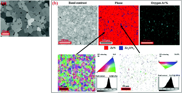 | ||
| Fig. 1 Polycrystalline ZrN (a) backscattered image and (b) EBSD mapping including band contrast, phases, oxygen and crystal orientations of ZrN and Zr2ON2 crystallites with inverse pole figures. (Reproduced with permission from the source84.) | ||
2.2 Preferred orientation
Preferred orientation or texture in NaCl-type fcc metal carbides and nitrides is governed by the conditions prevailing during the process of film growth.85,86,87 The film texture is determined by the lowest total energy conditions defined by a competition between surface energy and strain energy.43,88 In this type of structure, the (200) plane has the lowest surface energy while the lowest strain energy is exhibited by the (111) plane.89 The film deposition parameters that influence the balance between the surface and strain energy include reactive gas flow rate, chemical constitution, stoichiometry, deposition temperature, film thickness, substrate bias voltage, kinetic energy of incoming particles, etc. Various studies from the literature are cited below to elaborate this aspect of Zr-based coatings.Under synthesis conditions that use low kinetic energy particles where the strain energy is small and the surface energy is dominant, films grow in (200) preferred orientation. Use of high kinetic energy particles, where the strain energy is large and surface energy is less dominant, produces films with (111) preferred orientation.88,90 An opposite trend was observed in one study where ZrN coatings were noted to have (111) preferred orientation at 500 V beam energy, while the orientation changed to (200) at 700 V energy using the ion beam assisted deposition technique.42
Similarly, the thickness of the film also affects the preferred growth orientation. Beyond a critical film thickness, energy conditions change. At a small film thickness, the surface energy is dominant and gives rise to (200) texture. Beyond certain film thickness, the strain energy becomes dominant and texture changes to (111).88 ZrN thin films were produced using a DC reactive magnetron sputtering process.43 It was observed that thin films showed no preferred orientation while films with higher thickness exhibited strong (111) preferred orientation.
ZrN coatings were deposited at different nitrogen partial pressures using the DC magnetron sputtering technique.33 Lower N2 partial pressures of 7% and 11% produced ZrN with (111) preferred orientation while high pressures of 14% and 28% produced coatings with (200) orientation. In another study, a similar trend was observed. At low gas flow rates, (111) orientation was dominant. With an increase in the flow rate (i.e. with a change in the chemical constitution of the coating), the preferred orientation changed to (200).52 The increase of nitrogen flow rate increases the density of atomic N or N2+ ions which favors the (200) texture.86
X-ray spectra obtained for ZrNx films deposited using reactive DC magnetron sputtering with varying nitrogen flux ratios are shown in Fig. 2. It can be seen that at zero nitrogen influx the crystal structure is Zr hcp phase (002) texture. At low concentrations, nitrogen is present as an interstitial impurity in solid solution in the hcp lattice.83 With increasing nitrogen content, it changes to the ZrN cubic phase with predominant (111) preferred orientation. Oxide phases are not observed. An increase in nitrogen flux makes the ZrN(111) peak stronger reaching its highest intensity at 1% nitrogen flux when stoichiometric ZrN is formed. At still higher fluxes, the peak broadens as the phase becomes amorphous. ZrN films showed strong (111) preferred orientation. The (200) texture coefficient, defined by the ratio of the (200) peak intensity to the sum of the (200) and (111) peak intensities in the X-ray spectra, decreases with increasing nitrogen flux at various DC powers employed. It becomes the highest as the N/Zr ratio approaches stoichiometry. The authors have concluded that DC sputtering was highly dynamically controlled and was dominated by fast growing (111) planes. The growth rate of (200) was thought to be inhibited due to lattice distortion or interstitial site occupancy by excess nitrogen atoms.
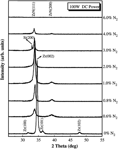 | ||
| Fig. 2 Series of XRD spectra obtained for ZrNx films produced with RF DC magnetron sputtering with various nitrogen flux levels.83 (Permission pending). | ||
The deposition temperature affected the texture which showed (111) preference up to 300 °C. At a deposition temperature of 500 °C, the (200) texture became stronger.43 Using CVD, stoichiometric fcc-ZrC coatings with a preferred orientation of (111) were obtained at a deposition temperature of 1600 °C.91 ZrC particulates produced with RF magnetron sputtering were observed to grow in (111) preferred orientation at a growth temperature, Ts, of 400 °C. The morphology became smooth as the temperature was increased.15 In another study, sub-stoichiometric ZrC grains were found to possess a (200) texture which became stronger after heat treatment.92
The dual cathodic arc ion deposition technique was used to grow ZrN on glass and aluminum substrates.93 X-ray diffraction patterns depicted mostly polycrystalline nature of the films, with preferential orientation of (200) planes in the −100 V to −300 V bias voltage range. For 70% nitrogen and at a bias voltage of −400 V, the (111) orientation of ZrN films predominated. The intensity of the (220) peak also increased at a higher bias. It was stated that at higher bias voltages, the coalescent energy of the adatoms for the growth of crystallites with (111) orientation becomes available. Film growth with this orientation serves to lower the increased strain energy.
In another study, it was observed that the preferred orientation for ZrN coatings deposited through the reactive magnetron sputtering technique changed from (200) to (111) with increasing substrate bias voltage, which was attributed to an increase in the biaxial compressive stress.34 A further increase in substrate bias voltage to −400 V led to a phase transition from substoichiometric to over-stoichiometric zirconium nitride with a Zr3N4 structure with high hardness. The thermodynamic calculation indicated that the evolution of preferred orientation and phase transition resulted due to a decrease in the strain energy.
ZrN(111) and ZrN(200) coatings were produced using arc evaporation.29 The crystallographic orientation of the coatings was thought to be influenced by the bias voltage, chamber pressure and deposition temperature. Low voltage (<100 V), low pressure (<2.4 Pa) and low temperature (<350 °C) produced ZrN with (200) orientation.
Synthesis of Zr3N4 is also reported in the literature.94,95,96 Zr3N4 has potential applications in mechanical, optical and microelectronic fields.97,98,99 A high negative substrate voltage of −400 V has been shown to form over-stoichiometric Zr3N4 phase using DC reactive magnetron sputtering.34 The grain size of ZrN films was reduced from 35.3 to 3.8 nm when the substrate voltage was changed from floating to −400 V. The nanocrystalline phase was Zr3N4 interspersed in amorphous ZrN or Zr3N4. Cross-sectional SEM images show a columnar morphology with a film thickness of 800 nm. A high deposition rate with large nitrogen content is also known to produce the Zr3N4 phase.
ZrYN coatings with 0 to 15 at% yttrium in the targets were deposited using DC magnetron sputtering.53 Yttrium atoms substituted zirconium atoms in the Zr–N lattice forming a ZrYN solid solution. The preferred orientation changed from (200) to (111), which was attributed to limited adatom diffusivity on (111) surfaces. This leads to larger cation residence times, and consequently, increases the probability of incorporating a higher number of cations on (111) compared to (200) oriented grains.100 Yttrium addition did not have an effect on grain size which was measured to be between 44 and 5 nm. This is expected of composite targets that result in a uniform deposition rate. Also, the (111) and (200) peaks shift to lower angles in XRD spectra indicating an increase in lattice parameter. The atomic radius of yttrium is larger than that of Zr. Substitution of Zr atoms by yttrium atoms changed the lattice parameter.
2.3 Hardness
Hardness is controlled by many factors such as preferred orientation, residual stress, grain size, defect density, stoichiometry and structure of the coatings which is turn depend largely on film growth conditions and process parameters including the synthesis technique, substrate bias, growth temperature, etc. The coating technique influences the structure of films, which in turn affects the mechanical properties of coatings.87 For instance, cathodic arc ion plating drives ions with high energy and momentum onto the growing film, which displaces atoms and produces a large density of point defects and lattice distortion. Grain growth is hindered due to continuous bombardment of incident ions producing fine grain size in a state of stress. The density of defects influences the texture and mechanical properties of the film. Hardness increases as the negative substrate bias is increased because it leads to the generation of a larger number of point defects. Similarly, hardness shows an increasing trend with the (111) texture coefficient which in turn is produced due to the high density of point defects generated by increased negative bias. Highly textured films show lowered grain boundary mobility as the latter's degree of coherency increases, thus increasing the resistance to deformation. The grain growth in textured films is also lower compared to that in randomly orientated films.101 It has also been suggested that textured nanostructured materials may have high activation energy for the strain rate102 and higher resistance to deformation when a load is applied suggesting that the hardness could increase with increasing degree of texture in films.The relative role of point defects and texture in coatings was evaluated by Tung et al.87 ZrN coatings produced using cathodic arc ion plating were heat treated which resulted in 36–49% decrease in hardness, from 29.8 to 15.2 GPa in one case while the (111) texture coefficient dropped only by 4% from 0.95 to 0.91. Such a small decrease in texture coefficient could not have been responsible for the significant decrease observed in hardness values. On the other hand, the defect density of the films was drastically lowered (i.e., reduced by half) upon heat treatment as represented by pronounced relief of intrinsic residual stresses. It was concluded that point defects were primarily responsible for the hardness of the coatings.
Nanoindentation hardness values of above 40 GPa were recorded for nanocrystalline ZrC coatings (6–20 nm grain size) under residual compressive stress prepared at substrate temperatures higher than 300 °C using the pulsed laser deposition technique.103 It was concluded that high hardness values are achieved for highly dense and nanocrystalline coatings. It was proposed that a highly dense nanostructured coating inhibits sliding or rotation of crystallites due to the lack of free space, thus giving rise to high hardness values.
In another study of ZrN films grown using dc magnetron sputtering, the intrinsic stress was 0.05 GPa (tensile) at floating voltage. At a substrate voltage of −80 V, it was compressive, −4.67 GPa. At −400 V, it was measured as −11.86 GPa.34 The hardness of ZrN films increases with an increase in negative substrate bias. At −160 V the hardness is 26 GPa. At −320 V, the hardness decreases to 22 GPa even though the compressive stresses increase indicating that stress hardening is not responsible for the evolution of hardness. The grain size decreases with an increase in substrate voltage to values of less than 10 nm at ≥−160 V. The hardness of the film decreases with a decrease in the grain size, which was attributed to intergranular deformation by grain boundary sliding (inverse Hall–Petch effect).104,105,106,107,108 At −400 V, the hardness increases to 28 GPa. High hardness at −400 V was attributed to phase change from ZrN to Zr3N4.
Smooth and compact ZrC coatings (600 nm in thickness, grain size 10 nm) were obtained on sand blasted pure titanium substrates using pulsed laser ablation.10 The deposition temperature was room temperature or 500 °C. Intrinsic hardness of the films decreased from 20 to 17 GPa with an increase in substrate temperature and molecular weight of carbides. In another study,15 it was observed that an increase in growth temperature from ambient to 400 °C did not affect nanoindentation hardness and elastic modulus.
Hardness increases with methane partial pressure, which increases the content of C.6 The magnitude of hardness increase depends on the Zr/C ratio employed.109 Carbides are usually harder but more brittle than nitrides. Multilayered coatings are harder than single layer coatings. Hardness is also affected by the period of bilayers in multilayered coatings. Hardness depends on the relative amounts of ZrCx and amorphous carbon present in the structure of coatings. A larger amount of amorphous carbon reduces the hardness of the coatings.110
Schmid factors for NaCl-type nitride coatings are 0, 0.25, and 0.5 for applied loading on the (111), (220), and (200) planes, respectively. Consequently, the (111) plane is harder than other planes owing to its lowest Schmid factor.111 ZrYN coatings were deposited using DC magnetron sputtering.53 The indentation hardness of the coatings first increases from 19.7 GPa to 24.1 GPa with increasing yttrium content up to 5 at%. The increase of hardness was attributed to the solid solution effect (due to yttrium alloying) and geometrical strengthening mechanism based on plastic deformation (more prominent (111) orientation). The hardness decreased to 20.9 GPa with a further increase in yttrium content up to 15 at%. This was related to the presence of high oxygen content in the coating.
The hardness increases as the (111) texture coefficient increases.86 However in one study, the opposite trend was observed. An arc evaporation process was used to produce ZrN(111) and ZrN(200) coatings consisting of a columnar structure with crystallite size varying from 14 to 42 nm.29 The microhardness of the coating was influenced by crystallographic orientation, microstrain and crystallite size. The microhardness was found to decrease with increasing I(111)/I(200) ratio once greater than 10. The crystallite size controlled the microhardness, which was inversely proportional to crystallite size. The microhardness of ZrN(200) was observed to be generally higher than that of ZrN(111). This was attributed to the finer crystallites formed in ZrN(200).
Cathodic arc evaporation was used to prepare ZrN, TiN and ZrTiN coatings.31 ZrN and TiN had comparable hardness values, i.e., around HV 2050, while ZrTiN exhibited hardness of HV 2590. ZrN was found to be brittle and showed lower resistance against cohesive failure compared to the other two coatings.
2.4 Residual stresses
The origin of total residual stresses in thin films is due to a combination of thermal stresses and intrinsic residual stresses. The thermal stresses are produced due to the difference in the thermal expansion coefficient between the film and substrate material, which can be calculated. The intrinsic residual stresses are generated due to the incident energetic particles impinging on film surfaces during deposition and are calculated by subtracting the thermal stresses from the total residual stresses.87 Preferred orientation influences the type and magnitude of stresses produced, which in turn affects mechanical properties and electrical resistivity of materials.83,112 Chemical constitution, substrate material and substrate voltage affect the type and magnitude of stresses produced. The compressive residual stress may increase hardness due to higher resistance to plastic deformation during indentation.86,113The lattice parameter value of random, stress-free and stoichiometric ZrN powder is 0.5585 nm. Slight changes in the lattice parameter could be attributed to residual stresses, impurities and small crystallite size (peak broadening). ZrN coatings were produced on various substrates such as Incoloy 825, Hastelloy C22 and Titanium grade 12 using cathodic arc sputtering.32 Coatings with compressive bi-axial in-plane stresses ranging from 2.69 to 4.06 GPa were obtained. It was stated that high residual stresses in the ZrN film were generated during growth due to the high bias and consequent high impact energy of the incident Zr ions. These residual stresses were attributed to intrinsic growth stresses and stresses generated because of thermal expansion mismatch between the substrates and the coatings. In another study,34 ZrN film was grown using dc magnetron sputtering. The intrinsic stress was 0.05 GPa (tensile) at floating voltage. At a substrate voltage of −80 V, it was compressive, −4.67 GPa. At −400 V, it was measured as −11.86 GPa.
In another study of ZrN films synthesized using hollow cathode discharge ion-plating,86 the residual stress was compressive. The residual stress of ZrN deposited on 304 SS was about 4 GPa higher than that of ZrN on Si substrate specimens. At the deposition temperature (450 °C), Si is harder than SS 304 steel. Therefore, it is comparatively difficult to introduce defects (and therefore stress) in the Si surface than in SS 304. For this reason, Si exhibits lower residual stress compared to SS 304 at any given nitrogen flow rate. On the other hand, a higher flow rate was required for Si to exhibit the same level of residual stresses shown by SS 304 steel. Since no phase transformation was observed during the growth process, the residual stress was composed of thermal stress and in-grown stress. The calculated thermal stress of the ZrN/304SS specimen was 1.69 GPa higher than that of ZrN/Si. The remaining residual stress could be accounted for by in-grown stress that depends on the substrate temperature, gas pressure and substrate bias.114 In another study,86 the substrate bias and temperature were fixed, indicating that the nitrogen flow rate was the main factor responsible for the generation of in-grown stress. The nitrogen flow rate was correlated with the ability of the Zr ions to impinge upon the substrate to produce defects that results in the development of stresses. As the flow rate is increased to a certain level, the probability of Zr ions interacting with gas molecules increases, thus decreasing the energy of Zr ions. This lowers the impingement effect of Zr ions on the substrate, lowering the in-grown stress.
In one study, the total residual stresses in ZrN coatings produced using a cathodic arc ion plating process were highly compressive, ranging from −11.6 GPa to −13.9 GPa and were thought to be due to the atomic peening effect. The thermal stresses were −1.65 GPa and −3.8 GPa for as-deposited and heat treated samples, respectively.87
ZrC films have been reported to show compressive stresses which change with carbon content. For instance, when carbon was increased from 44 to 88 at%, compressive stress increased from −0.4 GPa to a maximum of −1.4 GPa.110
2.5 Crystallinity, roughness and adhesion
The X-ray diffraction technique is used to measure the degree of crystallinity of coatings. Sharp symmetrical peaks in the XRD spectrum represent a crystalline sample. A shift away from the peak position of the target material or powder standard represents the presence of stresses. A shift toward the standard peak indicates stress relaxation.115 Crystallinity of ZrN coatings measured by FWHM of XRD peaks was observed to improve with increasing negative bias voltage in the cathodic arc ion deposition process.87 It was indicated that a high bias voltage increased the energy and momentum of ions in turn increasing the momentum transfer or energy condensation. This leads to an increase in adatom mobility and atomic diffusion, furthering the movement of adatoms to the equilibrium lattice sites and thereby improving the crystallinity of the coatings.In another study, it was observed that at a carbon content of 88 at%, the crystalline ZrCx phase disappears and only amorphous carbon (a-C) remains.110 High C/Zr ratio in ZrC films reduced roughness and produced smooth ZrC coatings.110 Root mean square roughness of the ZrN films follow the I(200)/I(111) ratio.116 Close packed planes such as (111) are smoother compared to the (200) planes. The highest roughness is recorded when a stoichiometric film is formed. Amorphous films depict low roughness.
The dual cathodic arc ion deposition technique was used to grow ZrN on glass and aluminum substrates.93 The films were smooth at a lower bias of −100 V, which was related to better compactness and quality of the film due to high energy imparted to the substrate by ions. The roughness increased slightly at a higher bias voltage possibly due to (increased) preferential re-sputtering of zirconium-rich clusters/islands. ZrN(111) orientation showed low roughness.
Improved adhesion was observed for ZrC coatings deposited at 200 °C and 400 °C compared with those deposited at ambient temperature.15 The ZrN films were deposited on M2 steel using an arc vapor ion deposition process.117 Scratch test results show that adhesion and film strength varied inversely with microhardness. The load required for lower critical failure increased as the bias voltage was increased. Hertzian cracking (fine cleavage diverging radially ahead of the indenter tip) was observed initially at loads of 5–20 N. Buckling, rippling and smearing without pulverization, all signs of lower critical failure were observed within the 30–60 N load range. Chipping and flaking were found within and at the edge of the groove due to cohesive and adhesive failure. Upper critical failure with exposure of the underlying substrate occurred at loads >90 N.
In another study, ZrYN coatings were synthesized using DC magnetron sputtering.53 Scratch failure modes included chip spallation on the side of the tracks, wedge spallation, and finally substrate exposure. These are considered common adhesion failure modes for coatings.118 Yttrium addition improved adhesion of the ZrYN coatings with the critical load increasing from 2.8 N for the ZrN coating to 7.6 N for the ZrYN coating.
2.6 Wear resistance
An earlier study on the subject concluded that the wear of a ZrN-coated drill was slower than that of a TiN-coated drill.119 The number of holes drilled before failure for the ZrN-coated drill were three times higher than that for the TiN-coated drill. In another study, tools coated with ZrN using the cathodic arc deposition process performed six times better than uncoated drills and 30% better than TiN-coated drills.120Friction and wear properties of TiN, ZrN and CrN coatings prepared using cathodic arc deposition were evaluated.38 All coatings exhibited a low degree of wear compared with that of the Inconel 718 substrate. The best wear performance was exhibited by CrN followed by ZrN and then TiN. At 500 °C, the wear performance of ZrN and CrN was comparable to and better than that of the uncoated couple, respectively. At 600 °C, the wear performance of CrN was markedly better than that of ZrN. Adhesive, oxidative and chemical wear mechanisms were responsible for the coating removal. Self-lubricating amorphous carbon is linked to the improvement in the friction coefficient and wear resistance of ZrC coatings.110
Zirconium nitride coatings were deposited on AISI 1045 steel substrates using a closed field unbalanced magnetron-sputtering ion-plating deposition process.35 The friction and wear behavior of coatings were evaluated at room temperature, 400 °C and 700 °C. The best tribological performance was exhibited by the coating tested at room temperature with the highest Vickers hardness and critical load (Lc) values and the lowest friction. The exposure at high temperature caused an increase in the friction coefficient of the coatings accompanied by a noticeable decrease in the composite hardness of the coating-substrate. At 700 °C, delamination of the coatings occurred due to the oxidation process of the unreactive zirconium micro-droplets.
2.7 Electrical resistivity
Bulk ZrNx has the lowest electrical resistivity of 13.6 μOhm m in all transition-metal nitrides. Its thermal stability (ΔH = −87.3 kcal mol−1) is superior to that of TiN (ΔH = −80.3 kcal mol−1).121,122 These properties make it a suitable candidate for diffusion barriers in IC technology.123,124 For ZrNx coatings with N/Zr atomic ratio <0.5 and produced using DC magnetron sputtering, nitrogen is present as an interstitial impurity in the lattice and the ZrNx thin film exhibits an Zr hcp solid solution structure.83 The presence of interstitial nitrogen in the Zr lattice inhibits grain growth causing an increase in the number of grain boundaries and distortion in the lattice. This gives rise to electron scattering which results in an increase in the resistivity of the film as the N/Zr ratio is increased from zero to 0.5. Once the N/Zr ratio is more than 0.5, phase transformation from Zr hcp to ZrN cubic takes place. Vacancies are present in the lattice due to non-stoichiometry. The resistivity now decreases toward stoichiometric ZrN. The presence of α-Zr and ZrN has been reported in the literature.125 A further increase in nitrogen content results in stoichiometric ZrN that displays minimum resistivity values. At this point, the deposition rate also decreases sharply due to ‘target poisoning’ where the target is covered with a layer of nitride whose sputtering yield is much lower than that of the pure Zr target. The deposition rate also decreases because argon is replaced by nitrogen in the system and sputtering capability of nitrogen is poor compared to argon. As the N/Zr ratio becomes larger than 1, the electrical resistivity increases rapidly.In another study, gold and metallic colored stoichiometric ZrN formed at a low nitrogen flow rate exhibited low resistivity. The resistivity increased gradually for films produced at 1–4 sccm value. A large increase in resistivity was recorded for green colored amorphous films deposited at ≥4 sccm.116 In another study, an electrical resistivity of 11.4 μOhm cm was obtained for a ZrN film deposited on a Si substrate at an ion energy of 150–200 eV and N/Zr ratio of 1.2–1.5 using ion assisted deposition.120,126 The ZrN coatings were deposited on steel and silicon substrates using magnetron sputtering.61 Unbiased films showed a high electrical resistivity (27![[thin space (1/6-em)]](https://www.rsc.org/images/entities/char_2009.gif) 000 μOhm cm). Use of bias lowered the resistivity. Between −80 and −100 V bias, the resistivity was measured at 500 μOhm cm. It decreased due to an increase in film density. For higher values of bias, the resistivity decreased to 200 μOhm cm.
000 μOhm cm). Use of bias lowered the resistivity. Between −80 and −100 V bias, the resistivity was measured at 500 μOhm cm. It decreased due to an increase in film density. For higher values of bias, the resistivity decreased to 200 μOhm cm.
The dual cathodic arc ion deposition technique was used to grow ZrN on glass and aluminum substrates.93 The ZrN film with (111) preferred orientation showed high resistivity (12.51 μOhm m) due to its close packed structure that enhances electron scattering. High resistivity was recorded for amorphous ZrN films. A larger amount of amorphous carbon increases electrical resistivity of the ZrC coatings.110
2.8 Corrosion, oxidation and erosion resistance
In one study,15 ZrC particulates with 5 nm grain size were observed to grow in (111) preferred orientation at a growth temperature, Ts, of 400 °C. The morphology became smooth as the temperature was increased. Improved adhesion, corrosion resistance and hemocompatibility were recorded for coatings deposited at 200 °C and 400 °C compared with those deposited at ambient temperature.The oxidation resistance of carbon fibers coated with ZrC in air at 600–1000 °C was found to increase by an order of magnitude while it was two to three orders higher in a carbon dioxide atmosphere compared to that in air.2
The oxidation behavior of ZrN coatings was compared in water vapor and air at 600 °C.45 The parabolic oxidation rate of ZrN in water vapor was two orders of magnitude higher than that in air due to large pores and high density of cracks that were formed across the ZrO2 oxide layer. A bilayered structure with tetragonal ZrO2 near the interface and monoclinic ZrO2 toward the outer surface was formed. The lateral cracks across the scale were formed due to volume expansion during a transition from the tetragonal to the monoclinic phase. It was suggested that stabilization of the tetragonal ZrO2 phase could lead to a denser scale providing better protection to Zr fuel cladding used in nuclear reactors.
The SPM oxidation technique was used to study the oxidation characteristics of ZrN films produced with the RF sputtering technique.116 Films produced with 0.5 sccm or lower nitrogen flow rate appeared brighter with little oxidation. High oxide features were visible on ZrNx prepared with higher nitrogen flow rates where the deposition rate is low, the electrical resistivity is large, and the films are amorphous. The formation of oxide structures in amorphous ZrN films was attributed to the lack of crystalline structure that promotes oxyanion transport through the oxide network.
ZrN coatings deposited on compressor blades made of titanium alloys using the vacuum ion plasma technique provided fair corrosion resistance without any decrease in the tensile and fatigue strength of substrate alloys. The coatings improved the resistance against gas abrasive wear up to 25–35 times. It was regarded as a suitable choice for blades and other gas turbine engine parts for use at 500 °C.41 ZrN coatings were prepared using the arc evaporation process.30 At 90° impact, the erosion was controlled by brittle fracture and plasticity at temperatures higher than 538 °C. The increase in erosion rate at temperatures higher than 538 °C was attributed to relaxation of residual compressive stresses in the coatings.
Numerous coatings including VN, VC, Cr3C2, ZrN and TiN, 15–30 μm in thickness, were prepared using the ion-plasma method and were tested for gas-abrasive wear resistance with flux containing 250–300 μm sand particles.40 It was concluded that stoichiometric ZrN coating is the most appropriate for protecting gas turbine compressor blades made of titanium alloys. A chromium carbide coating was found to be the best choice for protecting compressor steel blades.
2.9 Refractive index and aesthetics
Optical reflectance measurements and high energy X-ray photoemission spectroscopy (HE-XPS) were used to study the effect of 800 keV Ar ion irradiation on the optical and electronic properties of nanocrystalline ZrC and ZrN thin films obtained using the pulsed laser deposition technique.65 It was observed that irradiation affects the optical properties of the films primarily at low frequencies, which is dominated by the response of free carriers. A significant reduction in the free carrier scattering rate and an increase in zero frequency conductivity, i.e. a possible increase in mobility at higher irradiation fluence, were observed. It was concluded that irradiation affects the crystallite size and the micro-strain, but it does not induce major changes in the chemical bonding.ZrN films with various stoichiometries were produced using the ion beam assisted deposition method.64 At a N/Zr ratio of 0.98, the ZrN films showed characteristics of metallic materials such as high absorption in the IR range due to free electrons and a low absorption in the UV range. As the N/Zr ratio was increased, the refractive index increased and the extinction coefficient along with its slope decreased. This was attributed to a decrease in the free electron density or mobility. At a N/Zr ratio of 1.35, the extinction coefficient decreased with the increase of wavelength. The deposited films displayed dielectric behavior with increased electrical resistivity with increased N/Zr ratios.
The ZrN coatings were deposited on steel using magnetron sputtering.61 Optical properties close to those of bulk zirconium nitride were obtained for films deposited with a bias voltage of −110 V. High absorption in the IR range due to free electrons and a lower absorption in the UV range due to bound electrons and interband transition were observed.
ZrOx/ZrC–ZrN/Zr spectrally selective reflector-absorber tandem structures were deposited on stainless steel and Al substrates for absorptivity using the reactive DC/RF magnetron sputtering process. Hardness and elastic modulus increased from 20 to 39 GPa and 37 to 59 GPa respectively, with increasing nitrogen flow rate. It was observed that the films with moderate hardness and elastic modulus exhibited enhanced solar thermal performance (α ∼ 0.9) compared to those with lower and higher values. It was suggested that an optimal nitrogen concentration is required for the desired solar thermal performance.71
For RF sputtered ZrN, the color of the film changes from silver and gold to golden brown with nitrogen flow rates from 0 to 0.75 sccm. At a nitrogen flow rate of 3.5 sccm, the film exhibits a dark gray color. At ≥4 sccm nitrogen, the color is green.116 Dual ion beam sputtered Zr3N4 has been reported to exhibit a blue color.127 The argon flow rate has an inconsequential effect on the color of the film.128 From 0 to 10 sccm, ZrN films of silver, gold, brown, gray and green colors can be produced. At high flow rates beyond the golden color, the aesthetics of the films is reduced and become unappealing for the decorative industry.116 ZrN coatings were deposited on steel and silicon substrates using magnetron sputtering.61 A pronounced gold color was observed at −110 V. For other bias voltages, silver or brown colors were observed.
2.10 Mechanical strength
Tungsten fibers coated with ZrC protective coatings used in a composite material (WC + 6% Co alloy) served to improve the impact strength of the composite up to two times.3 Xin et al.129 prepared a ZrC coating with a thickness of 130 μm using reactive melt infiltration. It was determined that the compression strength of the coated sample was improved by 13.64% as compared with the graphite substrate. This was attributed to the increased density and particle reinforcement due to the ZrC infiltration and reaction of the melted Zr with the graphite substrate in the coating process.El Azhari et al.130 investigated the micro-mechanical properties of polycrystalline Zr(C,N) coatings deposited with the CVD technique (see Fig. 3a). Micro-pillars of Zr(C,N) were milled from within the coatings using focused ion beam equipment as shown in Fig. 3b. Micro-compression tests of pillars were undertaken using a nanoindenter equipped with a flat punch and inverse polar figure maps thus obtained are shown in Fig. 3c. The polycrystalline and columnar microstructure of pillars along with buckling is visible. The authors concluded that Zr(C,N) coatings show better micro-mechanical strength than Ti(C,N) coatings under cycling thermo-mechanical loads due to a combination of high hardness, cohesive strength and intrinsic plasticity.
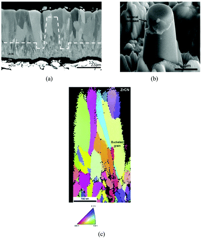 | ||
| Fig. 3 (a) Cross-sectional SEM image of Zr(C,N) coating, (b) view of Zr(C,N) pillar after compression test showing mixed inter/intragranular crack propagation mode. (c) Inverse pole figure map along the vertical axis. (Reproduced with permission from source.130) | ||
2.11 Wettability
Abdallah et al.131 studied the effect of deposition parameters on the wetting properties of ZrN films by calculating its surface free energy (SFE). They observed that the SFE decreased from 40.8 mN m−1 to 29.3 mN m−1 with an increase in N2 partial pressure ratio from 0 to 100%, respectively. Large values of SFE gives rise to a high degree of wettability. Authors attributed large SFE to the smooth and pore-free surface morphology of the film formed at a low nitrogen partial pressure. Concurrently, film roughness increased and the ZrN surface transformed from hydrophilic to hydrophobic with an increase in partial pressure.Blanco et al.132 evaluated the wettability of ionic liquids on TiN, CrN and ZrN coatings. They observed that ionic liquids with a lower surface tension leads to lower contact angles and high wetting. CrN was found to be the most hydrophobic while TiN was the most hydrophilic due to latter's large spreading parameter (SP) values recorded for tested ionic liquids. ZrN showed intermediate characteristics.
Reger et al.133 reported that the nitriding temperature had a strong influence on the wettability of ZrN coatings which improved due to the formation of nitride and oxynitride phases in pure Zr. The contact angle for pure Zr was measured as 98° while that for ZrN was 45° demonstrating increased wettability.
Patel et al.134 synthesized zirconium nitride coatings using reactive magnetron sputtering with argon as inert and nitrogen as reactive gas. The wettability properties were determined with a contact angle goniometer and indicated that the films were hydrophobic showing a high contact angle, e.g., 99.5°, at an Ar![[thin space (1/6-em)]](https://www.rsc.org/images/entities/char_2009.gif) :
:![[thin space (1/6-em)]](https://www.rsc.org/images/entities/char_2009.gif) N2 gas ratio of 20
N2 gas ratio of 20![[thin space (1/6-em)]](https://www.rsc.org/images/entities/char_2009.gif) :
:![[thin space (1/6-em)]](https://www.rsc.org/images/entities/char_2009.gif) 20 sccm, while a concurrent increase in surface roughness was observed with AFM. Hydrophobicity and roughness decreased when the amount of N2 was decreased, e.g., at a gas ratio of 20
20 sccm, while a concurrent increase in surface roughness was observed with AFM. Hydrophobicity and roughness decreased when the amount of N2 was decreased, e.g., at a gas ratio of 20![[thin space (1/6-em)]](https://www.rsc.org/images/entities/char_2009.gif) :
:![[thin space (1/6-em)]](https://www.rsc.org/images/entities/char_2009.gif) 4. It was suggested that the films produced with low N2 flow rates possess a smooth morphology and tend to have high wettability.
4. It was suggested that the films produced with low N2 flow rates possess a smooth morphology and tend to have high wettability.
3. Microstructure of Zr-carbide, Zr-nitride and Zr-carbonitride coatings
A study of the microstructure of coatings is important because it affects their properties including deformation fracture and wear behavior. Process parameters of deposition methods such as chemical composition, rate of deposition, temperature, voltage, etc. influence the microstructure of finished coatings. Chemical composition and bonding type affect the mechanical properties of finished coatings. Lower deposition rates give rise to smoother layers, while fine and dense grains deficient in columnar crystals are important for corrosion resistance and hardness properties.135,136 Some available techniques for examination and analysis of microstructures of coatings include atomic force microscopy, Auger electron spectroscopy, glow display optical spectrometry, Rutherford backscattering, scanning electron microscopy, and X-ray diffraction analysis amongst others. Out of these techniques popularly reported ones for the study of topography and morphology of coatings are SEM, AFM and XRD.A SEM produces images with a focused beam of electrons. The beam of electrons interact with atoms of coating samples to generate signals which can be read to get information about the sample's surface chemistry and topography. To use SEM, a cross-section of fracture coating samples is micrographed and analyzed for morphology. On the other hand, an atomic force microscope has very high resolution on the order of fractions of a nanometer. It can be used for atomic modifications and distinguishing samples based on examined mechanical properties. The third type of technique, X-ray diffraction, works on the principle of dispersion (diffraction) of X-radiation directed onto the surface of coatings. Diffraction patterns are dependent on the structure of the coatings and the wavelength of the X-ray. Patterns are saved as diffractograms and analyzed (read and interpreted) to get pore morphologies.
Growth of ZrC coatings was studied using the chemical vapor deposition technique.82 It was observed that a composite ZrC1.0 + C (ZrC within carbon matrix) coating gives rise to a spherical grain morphology. Stoichiometric ZrC1.0 appears columnar and flat with gaps and holes while sub-stoichiometric ZrC0.7 exhibits a fine micro-aggregate morphology with no obvious boundaries as shown in Fig. 4.
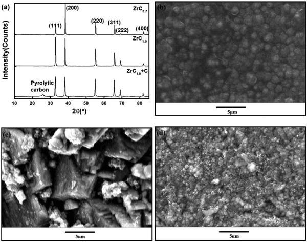 | ||
| Fig. 4 (a) XRD pattern, and SEM images of the coating surface (b) ZrC1.0 + C, (c) ZrC1.0, and (d) ZrC0.7. (Permission pending.) | ||
In another study15 undertaken using the RF magnetron sputtering technique, ZrC particulates with 5 nm grain size were observed to grow in (111) preferred orientation at a growth temperature, Ts, of 400 °C. The morphology became smooth as the temperature was increased. It was observed that the coating grain size increased from ambient to 400 °C.
Wang et al.80 deposited ZrC coatings using the chemical vapor deposition technique at various temperatures. At 1300 °C columnar morphology was observed while at 1400 °C equiaxed grains were produced. ZrC columnar grains with (220) preferred orientation were produced with the CVD technique.81
The SEM micrographs for some reported Zr-carbonitride coatings deposited using the dc reactive magnetron sputtering technique under low ion bombardment are as shown in Fig. 5(a)–(c).137 For lower nitrogen flow rates, a porous columnar morphology was reported, as shown in Fig. 5(a). An increase in nitrogen flow rate produced finer grains and denser morphology due to better re-nucleation of grains, as shown in Fig. 5(b) and (c). The X-ray diffractograms of the same samples, as shown in Fig. 6, show the patterns of the coatings compared to a series of other zirconium nitrides and zirconium carbide coatings (ZrxN1−x and ZrxC1−x). The report shows that Zr forms the α-Zr phase with nitrogen due to its capacity to incorporate a higher proportion of nitrogen.138 The manner of bonding between Zr and C in regime 1 is not decisive. Regime 2 (Zr/(C + N) = 1.3) shows (111) preferred orientation with a face centered cubic (fcc) structure. A higher proportion of carbon atoms are also noticed in the nitrogen positions which increases the chances of formation of Zr-carbonitride solution. In Regime 3 (Zr/(C + N) ≤0.7), a supplementary X-ray amorphous phase and lower degree of crystals are exhibited; the face-centered cubic structure is retained, however, with other preferred orientations when compared with region 2.
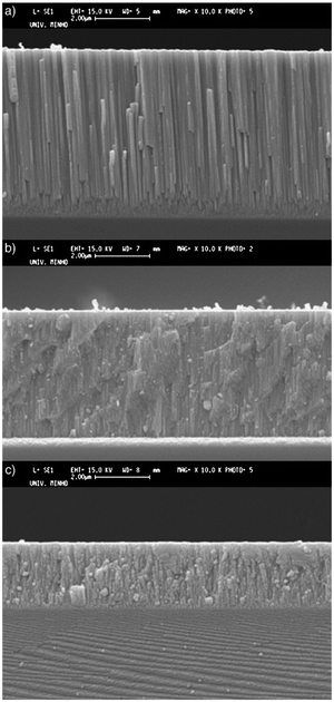 | ||
| Fig. 5 Cross-section SEM images of coatings synthesized at different N2 flows: (a) 2 sccm, (b) 6 sccm and (c) 10 sccm. (Reprinted from ref. 137 with permission from Elsevier.) | ||
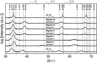 | ||
| Fig. 6 XRD spectra of ZrCN coatings developed from various regimes. (Reprinted from ref. 137 with permission from Elsevier.) | ||
Wang et al.139 researched the effect of microstructure of ZrC coatings on their ablation behaviors under the effect of an oxyacetylene torch. The concentration of hydrogen in the H2 + Ar dilution gas was varied in order to get different microstructures for the coatings. The coatings were characterized by numerous microcracks, which reduced with the introduction of hydrogen. As hydrogen concentration increased, the particle size decreased from micro to nanoscales and the preferred orientation changed from (111) to (200) and finally to (220). Cross-sectional SEM images of the coatings are shown in Fig. 7(a)–(h), while preferred orientation is evident in Fig. 8.
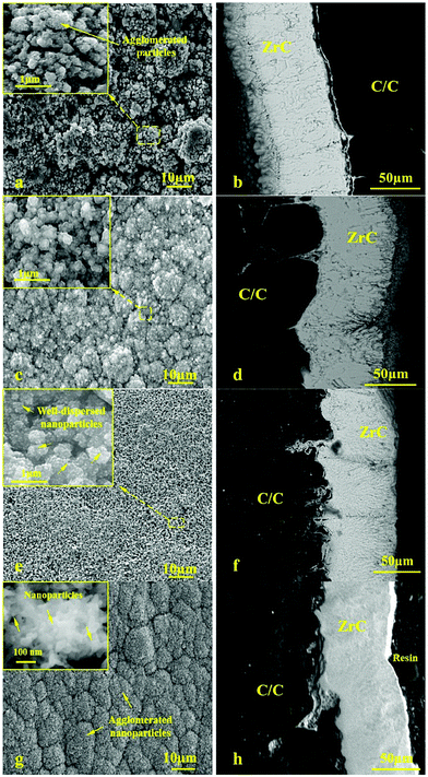 | ||
| Fig. 7 Cross-sectional SEM images of ZrC coatings deposited at H2 concentrations of (a and b) 0, (c and d) 30, (e and f) 50, and (g and h) 90. (Reprinted from ref. 139 with permission from Elsevier.) | ||
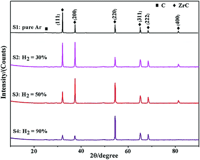 | ||
| Fig. 8 X-ray diffraction spectra of the ZrC coatings as a function of hydrogen concentration in the Ar + H2 dilution gas. (Reprinted from ref. 139 with permission from Elsevier.) | ||
3.1 Multilayered coatings
Braic et al.140 researched the effect of the C/N ratio and bilayer period on the protective coating properties of multi-layered Zr/ZrCN. Deposition of coatings was carried out using the cathodic arc deposition method with C45 and M2 steels as substrates. It was confirmed that the C/N ratio and multilayered period determined the micro-chemical, mechanical, microstructural and tribological characteristics of the coating. The recorded properties include bilayer period (Zr/ZrCN: 4.4–70 nm), hardness (ZrCN: 19.5–28 GPa, Zr/ZrCN: 10.4–21.4 GPa), scratch test adhesion critical load (ZrCN: 44–54 N, Zr/ZrCN: 74–43 N), surface roughness (ZrCN: 6.7–8.8 nm, Zr/ZrCN: 2.4–7.6 nm) and residual stress (ZrCN: 1040–1460 GPa, Zr/ZrCN: 590–1220 GPa). Multilayered ZrCN coatings showed improved properties compared to monolayered ZrCN coatings and the optimal structural properties of coatings were achieved between bilayer periods 6–13 nm.The XRD characterization of the ZrCN monolayer and Zr/ZrCN multilayers with bilayer period in the range of 4.4 to 25 nm is presented in Fig. 9.140 The monolayer showed strong preferred (111) orientation which is the most densly packed direction. In the case of the multilayer, reflections in the plane of (111) were accompanied by those in the plane of (220); however, those of multilayer (111) had wider peaks than the single layers.140 It was observed that there is a decrease in the bilayer periods from 25 nm to 4.4 nm; their diffraction pattern does not give any preferred orientation; however, the intensity ratio was found to reduce gradually to a value approaching unity.
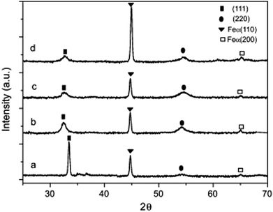 | ||
| Fig. 9 XRD patterns of (a) ZrCN (= 2 nm); (b) Zr/ZrCN (= 25 nm); (c) Zr/ZrCN (= 6.3 nm) and (d) Zr/ZrCN (= 4.4 nm) coatings. (Reprinted from ref. 140 with permission from Elsevier.) | ||
Similarly, the topography of ZrCN monolayers as well as Zr/ZrCN multilayers using AFM is shown in Fig. 10.
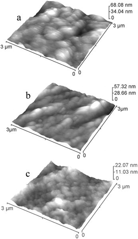 | ||
| Fig. 10 3 × 3 μm2 surface image by AFM of ZrCN and Zr/ZrCN-2 single and multilayer systems with (a) Λ = 25 nm, (b) Λ = 6.3 nm, and (c) Λ = 4.4 nm. (Reprinted from ref. 140 with permission from Elsevier.) | ||
Tribological tests were also conducted on the single and multilayered coatings and it was discovered that multilayers exhibited superior mechanical performance. The multilayers with Λ = 6.3 nm have better wear resistance due to their high hardness value as compared to Λ = 25 nm and Λ = 4.4 nm. Again, multilayer Λ = 6.3 nm coatings showed the lowest friction coefficient; however, multilayered structures with Λ = 25 nm and Λ = 4.4 nm showed tribological characteristics comparable to those of single layer coatings. The optimal structural properties of coatings were achieved between bilayer periods 6–13 nm. For bilayer period values of 4.1 nm, 6.3 nm and 25 nm, the first bilayer period showed no visible peaks, which indicates poorly defined layers. However, the last two multilayers showed visible superlattice peaks of different orders. Fig. 11 gives an illustration of the effects of bilayer period on the coating microstructure.
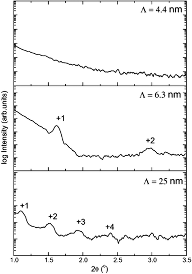 | ||
| Fig. 11 X-ray reflectometry scan of Zr/ZrCN multilayers with bi-layer periods of 25 nm, 6.3 nm and 4.4 nm. (Reprinted from ref. 140 with permission from Elsevier.) | ||
Abadias et al.141 researched epitaxial growth of ZrN/W multilayers using the dual ion beam sputtering (DIBS) deposition method on MgO(001) substrates with bilayer periods of 2.5 nm to 50 nm. X-ray diffraction (XRD) and transmission electron microscopy (TEM) were employed for analysis. The nanoindentation test, as shown in Fig. 12, showed that hardness is proportional to the bilayer period to the power of −0.54. The highest value of hardness (25.8 GPa) was recorded for a bilayer period of 2.5 nm. Changes in the materials components had a negligible effect and this was attributed to delamination at the W on the interfaces and large compressive stress as shown by the TEM image, shown in Fig. 13, and the XRD, shown in Fig. 14, results, respectively. Non-conformity to the rule of mixture value was also suggested to be due to little differences in shear modulus of the component materials. The epitaxial relationship recorded was [110](001)W//[100](001)ZrN//[100](001)MgO.
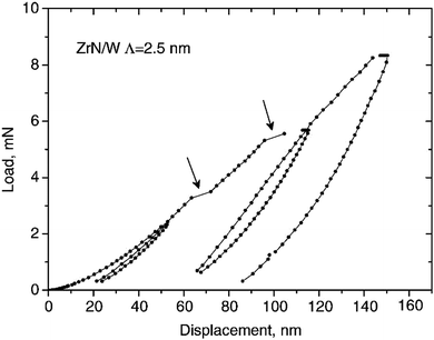 | ||
| Fig. 12 Nanoindentation test showing variation of load with displacement with λ = 2.5 nm for ZrN/W multilayer coatings. (Reprinted from ref. 141 with permission from Elsevier.) | ||
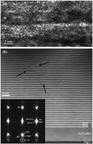 | ||
| Fig. 13 (a) Micrograph of multilayer ZrN/W with stacking λ = 5.2 nm as observed by HRTEM. (b) Light and dark image of ZrN heterostructures. (Reprinted from ref. 141 with permission from Elsevier.) | ||
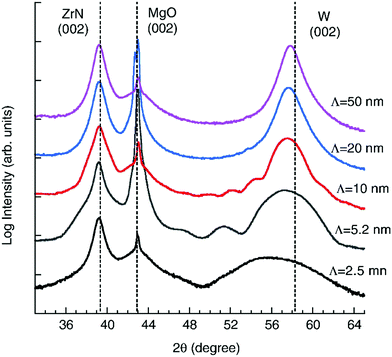 | ||
| Fig. 14 XRD evolution of the ω–2θ scans of multilayer coating of ZrN/W with different Λ. Straight lines (vertical) indicate reflection positions. (Reprinted from ref. 141 with permission from Elsevier.) | ||
Multilayered ZrC/ZrN and ZrC/ZrTiN films exhibited higher hardness values (32.4–33.2 GPa) but lower modulus values (251–270 GPa) when compared to the best quality ZrC coatings, i.e., 27.6 GPa and 228 GPa, respectively.115 Slightly higher concentration of oxygen (5.8%) was detected in the multilayered system compared to 3% for a monolayer ZrC. This was attributed to the longer time (approx. 20 minutes) required to grow the multilayered structure.
ZrC, TiN, and ZrC/TiN multilayer crystalline coatings with maximum thickness of 400 nm were grown on (100) Si substrates at 300 °C by the pulsed laser deposition (PLD) technique using a KrF excimer laser.142 Nanoindentation hardness of multilayers was between 35 and 38 GPa, higher than the 30–33 GPa for single layers of ZrC and TiN. The grain size of the Zr coatings was measured between 8–10 nm using XRD and TEM. In theory, an inverse Hall–Petch effect should influence hardness of ZrC at grain size of ≤9.4 nm.143,144 The effect, however, was not observed in this study.
4. Applications of Zr-carbide, Zr-nitride and Zr-carbonitride coatings
4.1 Zirconium-based coatings for tribological applications
Wang et al.139 researched the effect of microstructure of ZrC coating on their ablation behaviors under the effect of an oxyacetylene torch. Four samples of mass and linear ablation rates of 0.86–1.1 × 10⁻⁴ g s−1 and 0.23–0.47 × 10⁻³ mm s−1 respectively were tested over an ablation of 100 s. Results portrayed that increase in the concentration of hydrogen improved the microstructure and the in situ nanoparticles with (200) preferred orientation showed better ablation properties than the other preferred orientations possibly because of a crack-free ZrO2 layer formed with ZrO2 nanorods during ablation.ZrC coatings with Vickers hardness of 11 GPa were coated on the washers of cylindrical roller thrust bearings which were then tested for wear resistance in a test.14 The combined wear of the rollers and that of the two washers was very low (11–12 mg) after a 400 hour test, which indicated that the wear protection of the uncoated part was excellent.
In another study, a-C:Zrx% coatings were obtained with various Zr contents on WC–Co substrates using magnetron sputtering.9 Wear tests were conducted against an AISI 1045 steel counter body using an oscillating friction and wear tester system. The machining performance was also evaluated by performing turning tests and high-speed through-hole drilling tests. The experimental results reveal that the fabricated a-C:Zrx% coatings show improved tribological properties and machining performance. Optimal tribological properties were provided by the a-C:Zr13% coating while the best turning and drilling performance was obtained using the a-C:Zr45% coating.
Braic et al.145 evaluated the effect of heterogeneous deposition of ZrN coatings on microhardness, roughness, texture, adhesion, thickness, phase and elemental compositions of Si and high speed steel. Two different deposition methods (RF-PLD and RPMS) were employed with the same bilayer period of 50 nm. Scratch test, Vickers microhardness measurement, atomic force microscopy technique, as shown in Fig. 15, X-ray diffraction, as shown in Fig. 16(a)–(c), and Auger electron spectroscopy, as shown in Fig. 16(d), were employed to measure the desired properties of the coatings. It was discovered that for ZrN monolayers, stoichiometric behavior was almost independent of the coating deposition method. Multilayers of ZrN/TiN and TiN/ZrN exhibited minimum roughness and highest hardness value (about 30 and 32 GPa) for a bilayer period of 32 nm.
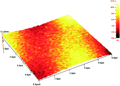 | ||
| Fig. 15 Atomic force spectroscopy (AFM) topology of bilayer ZrN/TiN-10/50 films by RPMS on Si substrates. (Reprinted from ref. 145 with permission from Elsevier.) | ||
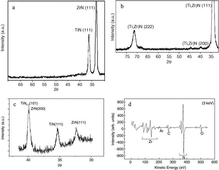 | ||
| Fig. 16 (a) XRD for TiN/ZrN multilayered coatings with (Λ = 50 nm, n = 10) deposited by RPMS, (b) single layer (Ti,Zr)N coating deposited by RPMS, (c) XRD spectrum of bilayer ZrN/TiN coating deposited by Radiofrequency beam assisted Pulsed Laser Deposition (RF-PLD), and (d) Augur electron spectroscopy spectrum of a ZrN layer in a TiN/ZrN-2/50 multilayer deposited by RPMS. (Reprinted from ref. 145 with permission from Elsevier.) | ||
Manier et al.146 proposed an improvement on the slip rolling resistance of zirconium based coatings with respect to the initial roughness of the surface after deposition and temperature stability. A novel coating–substrate system was compared to DLC coatings for slip rolling test in the presence of liquid lubricants. It was shown that with a minimum initial oil temperature of 120 °C under an initial contact pressure of about 3500 MPa, the novel coating–substrate system can produce a coated substrate that can withstand up to 1 million cycles with mixed/boundary conditions; in other words, about 10 million cycles under an initial maximum pressure of about 2940 MPa. They can be mass-produced due to their straight coating architecture and they do not need special oil formulations. In comparison, a number of slip rolling resistant tests were conducted on DLC coatings up to about 10 million cycles at room temperature and some others at 120 °C. It was emphasized that coatings on similar substrates and deposition conditions may not have the same slip-rolling resistance. This disparity in coating behavior might have occurred due to microstructural differences. To achieve higher and better slip-rolling resistance, a treatment such as pre- and post-mechanical surface treatment needs to be carried out. The pre-mechanical treatment is designed to remove surface oxides formed due to exposure of the surface to air and the post-mechanical surface treatment helps eliminate the droplets produced at the extinction of the deposition process. Because of disparity in slip-rolling resistance performance, investigation of high and poor slip-rolling resistant coating microstructures was done to examine and clarify the difference. The surface preparation of the samples was done with the focused ion beam technique and the imaging of the unstressed side of the samples was done using TEM as shown in Fig. 17.
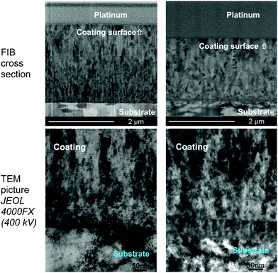 | ||
| Fig. 17 TEM investigations of Zr(C,N) coatings by means of FIB (high slip-rolling resistant coating on the left and poor slip-rolling resistant coating on the right). (Reprinted from ref. 146 with permission from Elsevier.) | ||
The friction behavior of Zr(C,N) was also examined as it affects the life span of the coatings. The coefficient of friction as a function of number of cycles for Zr(C,N) coatings as-deposited and after mechanical polishing of the coating is presented in Fig. 18.
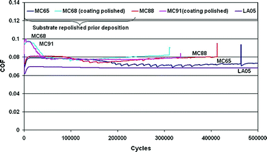 | ||
| Fig. 18 Coefficient of friction vs. number of cycles for Zr(C,N) coatings before and after mechanical polishing. (Reprinted from ref. 34 with permission from Elsevier.) | ||
Rie and Wohle135 investigated wear resistance properties of ZrCN. The effect of ZrCN coatings on the hardness of light metals (Mg & Al) was evaluated. Deposits were made on the light metals at low temperatures (below 180 °C) by the pulsed DC PACVD technique and the plasma state was examined using optical emission spectroscopy (OES). It was found that the hardness of ZrCN is affected by its carbon concentration, which is also reported in other literature. Also, the hardness of ZrCN increased with increasing discharge voltage. The recorded harness of ZrCN was 1400 HK0.01 and the growth rate of ZrCN was at least two times that of TiCN.
ZrCN coatings prepared by Manier et al.146 were able to withstand at least 1 million cycles under Hertzian contact pressures of up to P0(max) = 3500 MPa and oil temperatures of 120 °C showing low coefficients of friction and good wear resistance. At P0(max) = 2490 MPa, it withstood ten million cycles. The authors concluded that ZrCN coatings do not require special oil formulations to demonstrate good slip-rolling resistance.
Chang et al.147 evaluated the mechanical and impact resistance properties of monolayered and multilayered TiAlN/ZrN coatings deposited using the cathodic arc evaporation technique with plasma enhanced duct equipment. Cathodes of TiAl (50 at% Al) and zirconium were utilized for the coating deposition. The multilayered coatings were deposited as interlayers with different modulation periods, chemical compositions and cathode current ratios (I[TiAl]/I[Zr]) ranging from 0.75 to 1.33. The coating layer thickness ratio and modulation period increased with the cathode current ratio. The evaporation rate of the cathodes determined the alloy content and nanolayer thickness of the deposited coatings. The hardness, as shown in Fig. 19(a), exhibited by ZrN monolayer coatings (30 GPa) was lower than that for the TiAlN/ZrN multilayer coatings (33–38 GPa). The impact resistance, shown in Fig. 19(b), and resistance to plastic deformation of monolayered coatings were also lower as compared to multilayered coatings, e.g. a TiAlN/ZrN multilayered coating which had the highest resistance to plastic deformation (H3/E*2 of about 0.443 GPa), the best impact resistance (1 × 10⁵ impacts), lowest modulation (25 nm) and the highest layer thickness ratio (0.92) amongst the tested mono- and multilayered coatings.
 | ||
| Fig. 19 (a) Hardness and elastic modulus of multilayered TiAlN/ZrN, TiAlN/ZrN-1.0, and TiAlN/ZrN-1.33. (b) Impact resistance of single layered ZrN and TiAlN as well as multilayered TiAlN/ZrN-0.75, TiAlN/ZrN-1.0 and TiAlN/ZrN-1.33 coatings. (Reprinted from ref. 147 with permission from Elsevier.) | ||
Kudapa et al.148 investigated nanolayer and monolayer ZrCN and TiCN based coatings with the view of increasing their toughness especially in cutting tool applications. The coatings were deposited by the medium temperature chemical vapor method. Optical microscopy, scanning electron microscopy, as in Fig. 20, and X-ray diffraction were employed for characterization. It was recorded that the ZrCN layer in a 40-layer alternating stacking sequence reflected the preferential orientation of the starting layer. The MTCVD nanolayer TiCN/ZrCN had a preferential orientation of (311), while the monolayer counterpart had an orientation of (220). The nanolayer coatings displayed higher failure load as compared to monolayers, which may be attributed to the improved superficial strength of their layers. MTCVD ZrCN exhibited increased brittleness and a critical load of 25–35% higher when compared to MTCVD TiCN in the crack resistance test. However, the MTCVD nanolayer TiCN/ZrCN exhibited the lowest surface roughness.
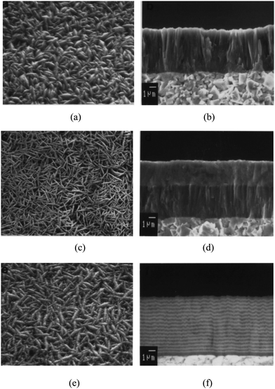 | ||
| Fig. 20 Scanning electron microscopy (SEM) images of (a) monolayer TiCN as-coated surface, (b) fracture surface monolayer TiCN coating, (c) surface morphology of as-coated bilayer TiCN/ZrCN, (d) fracture surface of bilayered TiCN/ZrCN; (e and f) surface morphology and fracture surface of nanolayer TiCN/ZrCN, respectively. (Reprinted from ref. 148 with permission from Elsevier.) | ||
4.2 Applications for corrosion and oxidation resistance
Budke et al.149 studied the corrosion resistance of ZrN hard coatings used in the bathroom equipment. The authors stated that an improvement of the corrosion resistance of bathroom facilities could occur when coated with ZrN coatings. By changing the sputter conditions in the coating process, the coating resistance of this type of coating could be significantly improved.Investigation of corrosion resistance of ZrCN hard coatings on brass alloy (40% Zn and 60% Cu) was reported by Gu et al..150 In their work, ZrCN was deposited on the surface of brass using arc plasma deposition and it was discovered that the corrosion resistance of ZrCN coatings on brass is higher than that of the electroplated Ni/Cr coating. The ZrCN inert surface is effective in preventing the substrate from corrosion. It was concluded that ZrCN hard coatings offer higher corrosion resistance and improve the quality of bathroom accessories.
Xu et al.151 applied ZrC nanocrystalline coating on a Ti-6Al-4V alloy for corrosion protection. In this study, nanocrystalline ZrC was coated on the Ti-6Al-4V substrate by the double glow discharge plasma technique. The corrosion behavior was investigated using electrochemical techniques at three solution temperatures (25 °C, 55 °C and 70 °C). It was clearly observed that with an increase in the temperature; the number of defects on the surface of the passive film increases; thus the passive layer formed was less protective at higher temperatures. However, the number of defects formed in the passive film with an increase in temperature for the ZrC coated specimen, as shown in Fig. 21(a), is significantly lower than that for uncoated Ti-6Al-4V, as shown in Fig. 21(b) under the same conditions. It was concluded that the ZrC coating is more hydrophobic than uncoated Ti-6Al-4V and this precludes accumulated water from flooding the electrode surfaces and at the same time mitigates the extent of corrosive attack.
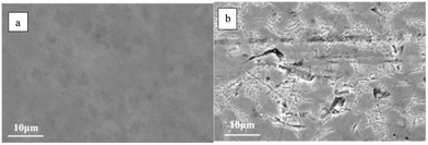 | ||
| Fig. 21 The corroded surface morphologies of bare and the ZrC coated Ti-6A1-4V after potentiodynamic polarization tests in a 0.5 M H2SO4 + 2 ppm HF solution at 25 and 50 °C: (a) uncoated Ti-6Al-4V and (b) ZrC coated. (Reprinted from ref. 151 with permission from Elsevier.) | ||
Ferreira et al.152 studied the corrosion resistance of magnetron sputtered ZrN and ZrSiN on AISI 430. It was concluded that the ZrSiN coating was more effective than ZrN in protecting steels against corrosion. The ZrN coated AISI 430 steel showed a localized corrosion through pores in the coating; however, the ZrSiN coated AISI 430 steel showed a uniform corrosion at the coating–steel interface.
Zhao153 studied the oxidation behavior of TiAlZrCr/(Ti,Al,Zr,Cr)N gradient film in different temperature ranges for short (600–900 °C for 4 h) and long (700 & 800 °C for 100 h) term cyclic tests, respectively. Coatings were deposited on high-speed steel (W-18Cr-4V) substrates by means of the multi-arc ion plating technique. Sample characterization was undertaken using X-ray diffraction (XRD), energy dispersion X-ray spectroscopy (EDS) and scanning electron microscopy (SEM). The long-term cyclic test produced excellent oxidation resistance up to a temperature of about 700 °C, while the short-term cyclic test produced excellent oxidation resistance up to a temperature of about 800 °C. After these, oxide scales of TiO2 were observed.
4.3 Biomedical and bioelectronic applications
To the best of our knowledge, Helmer and Driskell154 presented the first reference for medical application of zirconium in 1969. Two decades later, the application of zirconium in medical surgery was published,155 followed by dental applications in the early 1990s.156 In 1975, Cranin et al.157 reported the first experimental work on zirconium based materials after which a good number of publications have been reported on medical applications of zirconium. Zirconium based compounds are especially employed in odontology, coating of surgical tools, medical implants etc. because of their periointegration, biocompatibility, bio-inertness, minimized bacterial settling and osseo-conductiveness.158–160For biomedical applications, coatings need to resist dissolution in aggressive media containing chloride ions so as not to contaminate the organism. Any dissolution will degrade biocompatibility and affect the mechanical strength of the prosthesis.161 Likewise, bioelectronic devices containing solid electrodes surrounded by concentrated aqueous solutions of biological molecules need to be protected from corrosive reactions.43In vivo test, in vitro test and clinical trials are carried out to ascertain the feasibility of potential zirconium based coatings in medical applications.
Titanium is widely used as a dental/orthopedic implant material due to its excellent mechanical properties, corrosion resistance, biocompatibility, and osseointegration. However, a titanium implant cannot integrate chemically to the surrounding bone. In addition, titanium does not possess any antibacterial activity, the lack of which can lead to plaque formation, inflammation or infection after surgery. Antibacterial activity can be achieved with a coating such as ZrN or TiN, which retains titanium's biocompatibility. Inflammatory processes are initiated with the adsorption of biomolecular pellicles and the subsequent accumulation of bacteria on implant surfaces. Coatings on implant surfaces can influence the adherence and spreading of cells, thereby controlling the osseointegration process. The degree of osseointegration of Ti implant depends on its composition and surface treatment.
ZrN has been reported to possess the capacity for reduction of plaques on implants and neighboring tissues bringing about successful implants at the bone level and healing of soft tissues.162 Ramoul et al.163 studied the wear, corrosion and antibiotic properties of the PVD ZrN coatings prepared by the RF magnetron sputtering method. They concluded that the coatings not only showed good wear resistance but also exhibited good corrosion resistance and a strong biocide effect. Thus, the coatings could find potential use in biomedical applications. Other authors have also found ZrN to be biocompatible and a potential candidate for use as coatings on biomaterials.164
Biologic performance of titanium dental implants coated with zirconium nitride was evaluated in a murine preosteoblast cellular model.55 The coating was deposited by means of physical vapor deposition. It was found that the coating was effective in covering titanium surfaces with zirconium nitride. A significantly higher number of cells adhered and spread onto zirconium nitride-coated surfaces (P < 0.05) after 24 hours. After 7 days, both titanium and zirconium nitride surfaces were completely covered with MC-3T3 cells. It was concluded that the ZrN coating could render the surface of the titanium more bioactive than uncoated titanium surfaces. ZrN coatings were deposited on Ti based alloys using PVD to improve cytological properties. The performance along with the color of the coatings was found to be satisfactory for the success of implant therapy.56
Antibacterial activity and osteoblast-like cell viability according to the ratio of titanium nitride and zirconium nitride coating on commercially pure titanium using an arc ion plating system were evaluated.57 It was observed that the number of S. mutans colonies on the TiN, ZrN and (Ti1−xZrx)N coated surface decreased significantly compared to those on the non-coated titanium surface (P < 0.05).
An in vitro study was performed to check the biocompatibility and antibacterial properties of ZrN on titanium abutments.58 For all tested bacterial strains, biofilms grown on the ZrN surface showed a higher percentage of dead bacteria than on the other disks. No hemolytic activity was detected and the surfaces' clinical safety was confirmed. Another in vitro study demonstrated the effectiveness of ZrN coating in reducing the Staphylococcus epidermidis biofilm formation on orthopedic implant surfaces.60
ZrN coated knee implant was designed for patients with suspected metal ion hypersensitivity and compared with an uncoated implant made of CoCrMo alloy.59 Tribological tests showed a significant wear rate reduction for the ZrN coated implant. The ZrN coating showed no sign of scratches or delamination during the wear simulation, whereas the uncoated femurs showed characteristic wear scratches in the articulation areas. Furthermore, the metal ion release from the coated implants was reduced up to three orders of magnitude in comparison with the uncoated implants.
In another study,79 carbonitride coatings doped with 6 at% W, Ti, Zr, or Cr were prepared on biograde AISI SS316L substrates. The antimicrobial test used Staphylococcus aureus. The results showed that the coating was a composite of amorphous carbonitride and amorphous C structures. The coating with doped Zr exhibited the highest hydrophilicity and the best antibacterial performance. However, its wear resistance was poorer than coatings doped with W and Ti. The Ti-doped coating exhibited the lowest antibacterial capability.
ZrN thin films prepared using DC reactive magnetron sputtering were evaluated for corrosion resistance in biological medium.43 Coatings were found to be stable over a large potential range in a medium of artificial saliva. The coatings’ deposition temperature and the oxidation of the surface during synthesis played an important role in the corrosion behavior. It was observed that pitting potential increased with increasing deposition temperature. For deposition at 500 °C, the pitting potential was found to be Ep = 1.5 V per SCE. At higher deposition temperatures, the corrosion behavior worsened due to the formation of thin ZrNxOy and ZrO2 layers on the top surface of the films.
ZrN coatings have been successfully used in the corrosion protection of Ti-6Al-4V alloy used in biomedical applications. In their studies, Kadam et al.165 coated the Ti-6Al-4V alloy with a ZrN coating using cathodic arc physical vapor deposition so as to enhance the corrosion performance and surface properties.
Dense and smooth ZrC and ZrN thin coatings were deposited on Ti and Si samples using pulse laser deposition.16 Coatings were found to be nanocrystalline with 5–12 nm grain size and under compression. Electrochemical tests performed in simulated body fluid for 32 days showed that the corrosion resistance of Ti samples was significantly improved due to coatings. The best performance was delivered by ZrN whose corrosion current remained almost unchanged during the course of the study.
Hollstein et al.166 evaluated the protective properties of ZrCN for low reflective PVD-arc coatings for surgical tool applications. It was found that after storage for some days under normal environmental conditions, coated materials developed higher concentration of oxygen and carbon in their layers, a phenomenon requiring more research for a better understanding.
Lai et al.167 researched the effect of carbon content on bacteria inhibition performance of ZrCN/a-C coatings for medical applications. Non-composite ZrC/amorphous carbon (a-C) was deposited on titanium implants by a cathodic arc evaporation system. It was recorded that above 12.7 at%, ZrCN/a-C exhibits good HGF cell compatibility and bacterial (A. actinomycetemcomitans) repulsion properties.
Balaceanu et al.168 researched adhesion and hardness properties of single (ZrCN) and multilayered (Zr/ZrCN) zirconium based coatings for possible adoption in medical implant applications. Coatings were deposited by the magnetron sputtering method after which characterization was carried out. It was recorded that multilayered coatings responded better in terms of humoral immune with no adverse effect on the blood system. Hardness, bilayer period and critical load were in the range of ZrCN 19.5–28 GPa, Zr/ZrCN 10.6–29.4 GPa, Zr/ZrCN 4.4–70, and ZrCN 43–44 N, Zr/ZrCN 43–71 N respectively. It was reported that the hardness of ZrCN and Zr\ZrCN films was improved with increasing carbon concentration. Besides, adhesion of coating onto the surface of implant is more vital than the hardness of the coating in biomedical applications. The results of the analyses conducted on peri-implant tissues using HE staining and MMP-8 detection are presented in Fig. 22 for the coated and uncoated 316 L implants.
 | ||
| Fig. 22 316 L uncoated implant tissues after 8 weeks by DAB IHC: (a) HE detection and (b) MMP-8 detection. (Reprinted from ref. 168 with permission from Elsevier.) | ||
Nanocomposite ZrCN/amorphous carbon coatings were deposited on a biograde pure Ti implant material using a cathodic-arc evaporation system.167 Due to the small dissociation energy of C–H bonds and due to increasing carbon content caused by a high C2H2 flow rate, the carbon/nitrogen ratio increased. The flow rate of acetylene gas and nitrogen can be used to control the amount of amorphous carbon and C–N bonds. Carbon atoms substituted for nitrogen lattice positions resulted in lattice expansion. Only a small fraction of carbon was in the form of a-C phase in the coatings. The contact angles (86–92°) of coated samples were higher than that of Ti (55 ± 1.3°), showing hydrophobic nature. A pathogen Actinobacillus actinomycetemcomitans commonly associated with dental implant infections was selected for in vitro anti-bacterial analyses. It was found that the ZrCN/a-C coatings with carbon content higher than 12.7 at% improved antibacterial performance with excellent HGF cell compatibility.
Radio frequency magnetron sputtering was used to produce zirconium carbonitride coatings on AISI 316 L austenitic stainless steel.75 Coatings were almost amorphous at a growth temperature of less than 400 °C, while nanostructured Zr2CN was formed at Ts of 400 °C. Nanostructured zirconium carbonitride coatings showed improved corrosion resistance. The coatings exhibited better hemocompatibility when Ts varied from 25 °C to more than 200 °C, which was attributed to lower surface roughness and interfacial tension.
Hip joint prostheses are increasingly used due to an increase in elderly population. However, an estimated 20% of hip replacement surgeries fail within a few years due to wear fatigue. This provides a basis for continued research in this field. In this context, ZrCN coatings with silver additions were produced and tested. Silver is a well-known anti-bacterial agent. Zirconium carbonitride (ZrC1−xNx−nAg) coatings with silver nanoparticles were deposited on stainless steel SS316 and silicon (100) for use with biomedical devices using DC unbalanced dual magnetron sputtering. Two targets Zr and Zr/Ag were used in Ar, C2H2 and N2 atmospheres. Electrochemical characterization showed stable coatings that improved corrosion resistance of the base material with low amounts of Ag having no deleterious effect. Grain growth and columnar morphology were found to deteriorate the corrosion resistance.72 The best mechanical and electrochemical performance was shown by the stoichiometric ZrC0.5N0.5 phase with <8 at% of silver and residual oxygen. Higher amounts of Ag had deleterious effects on corrosion resistance.169 An increase in Ag content resulted in the formation of the a-CNx amorphous phase in addition to a silver crystalline phase. Hardness decreased, as silver content increased. Adhesion values were considered to be good.74 Amorphous carbon had a negative influence on the polarization resistant attributed to morphological changes.77 The antimicrobial activity of the coatings was tested against pathogen staphylococcus epidermidis. It was found that the silver activation process was essential for antimicrobial activity, as observed with 11 at% of Ag which was found to diffuse to the coating's surface.76 It was demonstrated that coatings with silver nanoparticles encapsulated in an amorphous phase reveal a large bacterial zone of inhibition. Antibacterial effect of coatings was shown to depend on the release of silver ions and on the availability of silver nanoparticles at the surface.78
ZrCN coatings with silver addition were produced by dual magnetron sputtering. Silver is added to enhance the absorption at specific wavelengths, to provide self-lubricating properties at high temperatures, to alter the resistivity of the coatings and to incorporate antimicrobial characteristics. A highly oxidized surface was produced due to the affinity of Zr to form ZrO2, and due to silver segregation to the surface. Silver nanoparticles of 5–20 nm size were distributed in the ZrCN matrix. Silver was also agglomerated at the surface with size <80 nm.70
4.4 Nuclear fuel applications
As stated in the introduction, ZrC has been used as a coating on nuclear fuels employed in gas cooled nuclear reactors since Reynolds et al. carried out initial work in 1976.4,5 ZrC can be used in three ways.170 Firstly, fine-grained ZrC can be coated on the uranium oxide kernel of TRISO fuels to act as an oxygen getter. During high fuel burn-up, ZrC serves to buffer oxygen evolved during the fission of UO2 thus preventing adverse oxidative reactions. Secondly, ZrC can be used to substitute SiC in TRISO to act as a pressure vessel due to its resistance to diffusion of fission products and to high temperature degradation. Thirdly, both of these applications can be combined together to maximize the benefit. ZrC was found to be stable under fast neutron irradiation at a high temperature of 1496 °C.170 Over the years, considerable work evaluating properties of ZrC for use in nuclear fuel reactors has been undertaken.80,81,91,92,170–181In nuclear reactors, the fuel in the reactor core is isolated from the coolant (operated at less than 600 °C) by using a fuel cladding made of ferritic or martensitic stainless steel. Chemical reactions between the fuel and the cladding material at elevated temperatures can threaten the integrity of the cladding. TiN and ZrN coatings produced using pulsed laser deposition have been proposed as suitable materials to act as a diffusion barrier between the stainless steel cladding and fuel.47 ZrN has low neutron absorption and high melting temperature. It was shown to prevent diffusion of Ce and other lanthanide fission products encountered in nuclear fuel technology.
In another study,46 protective coating of ZrN was spontaneously formed in a eutectic based on lead (with 2.25 wt% magnesium and 0.2 wt% zirconium) on a steel surface in order to decrease the interaction between the sublayer in a fuel element and the fuel-element cladding. Gravimetric analysis showed that the ZrN increased the service lifetime of the fuel assemblies. It was concluded that the maximum mass loss will be 0.12 kg m−2 and the maximum thinning of the fuel-element wall will be 15 μm during 35![[thin space (1/6-em)]](https://www.rsc.org/images/entities/char_2009.gif) 000 hours of service.
000 hours of service.
The potential of ZrN as a protective coating for radioactive waste storage vessels was evaluated by depositing it on various substrates such as Incoloy 825, Hastelloy C22 and Titanium grade 12 using cathodic arc sputtering.32 Dense coatings with thickness of around 5 μm were obtained with compressive stresses ranging from 2.69 to 4.06 GPa. Nanoindentation hardness and elastic modulus values of 27.65 GPa and 458 GPa were obtained. The interface exhibited the formation of compounds with elements from coatings and the substrate material, which were believed to aid in coating adhesion (Fig. 23).
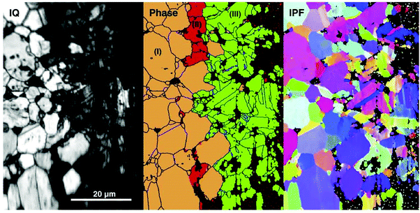 | ||
| Fig. 23 Image quality (IQ) map, phase distribution and inverse polar figure maps obtained from ZrN (orange) after reaction with Pd (green). (Reprinted with permission from the source182.) | ||
ZrC and ZrN are candidate materials to replace SiC as a coating layer on nuclear fuel particles used in gas-cooled fast reactor systems. In this context, Tan et al.182 examined the resistance to Pd attack of TiC, ZrC, TiN, and ZrN with diffusion couples annealed at 1400 °C for 10 h. All materials were found to offer better resistance than SiC. The tested materials were ranked from the top as TiN, ZrN, TiC and ZrC.
Nanocomposite ZrCN/amorphous carbon coatings deposited on pure Ti using a cathodic-arc evaporation system167 possessed a high contact angle (86–92°), which was much higher than that of Ti (55 ± 1.3°), confirming its hydrophobic nature.
5. Conclusions and recommendations
The applications of zirconium carbide, zirconium nitride and zirconium carbonitride coatings are made possible by the remarkable properties of zirconium. These properties include high temperature ionic conductivity, corrosion resistivity, good wear resistance, elevated fracture toughness, hardness, and strength. Zirconium has high thermal expansion and modulus of elasticity. These properties enable development of Zr-based protective coatings for mechanical, chemical, nuclear and biomedical applications.The properties of coatings depend on their chemical and phase constitution, stoichiometry, microstructure, crystallinity and preferred orientation, which in turn depend on deposition conditions during synthesis. Columnar morphology was observed at a deposition temperature of 1300 °C while equiaxed growth was reported at 1400 °C with CVD. A smaller crystallite size with higher microhardness values was observed at lower deposition temperatures. ZrC coatings produced with CVD exhibit a decrease in grain size with an increase in carbon content. Over-stoichiometric coatings show a spherical grain morphology. Stoichiometric ZrC appears columnar while sub-stoichiometric films display a fine micro-aggregate morphology with no obvious boundaries.
The (200) plane has the lowest surface energy while the lowest strain energy is exhibited by the (111) plane. With low kinetic energy particles where the strain energy is small and the surface energy is dominant, films grow in (200) preferred orientation. Use of high kinetic energy particles, where the strain energy is large and surface energy is less dominant, produces films with (111) preferred orientation. At small film thickness, the surface energy is dominant and gives rise to (200) texture. Beyond a certain film thickness, the strain energy becomes dominant and texture changes to (111). Lower N2 partial pressures produced ZrN with (111) preferred orientation while high pressures produced coatings with (200) orientation. The deposition temperature affected the texture which showed (111) preference up to 300 °C. At a deposition temperature of 500 °C, (200) texture became stronger. At high negative substrate bias, (111) growth is preferred.
Hardness is controlled by many factors such as preferred orientation, residual stress, grain size, defect density, stoichiometry and structure of the coatings which is turn depend largely on film growth conditions and process parameters. Heat treatment decreases hardness. Dense and nanosized coatings display high values of hardness. Hardness increases with increasing nitrogen or methane flow rates to a certain extent. (111) texture coefficient has the highest hardness. A high bias substrate voltage increases the crystallinity of films. At low bias, smooth films are produced. A high C/Zr ratio in ZrC films reduces roughness and produces smooth ZrC coatings. Adhesion and strength vary inversely with hardness. Self-lubricating amorphous carbon improves the friction coefficient and wear resistance of ZrC coatings.
Formation of soft amorphous carbon or CNx exhibits low hardness, friction and high resistivity. Over-stoichiometric films also exhibit higher resistivity. Improved adhesion, corrosion resistance and hemocompatibility were recorded for coatings deposited at 200 °C and 400 °C compared with those deposited at ambient temperature. The films with moderate hardness and elastic modulus exhibited enhanced solar thermal performance (α ∼ 0.9) compared to those with lower and higher values. From 0 to 10 sccm, ZrN films of silver, gold, brown, gray and green colors can be produced. The argon flow rate does not affect the color of the film.
Future work can include corrosion resistance applications of Zr-carbide, Zr-nitride and Zr-carbonitride coatings and their behavior in a humid environment. In addition, natural oxidation of stored coated materials, medical applications of Zr-based coatings especially in implants and better adhesion of coatings on substrates amongst others require further in-depth research.
Conflicts of interest
There are no conflicts to declare.Acknowledgements
The support of Deanship of Scientific Research (DSR) at the King Fahd University of Petroleum & Minerals (KFUPM), Dhahran, Saudi Arabia, through project no. SB191053 is gratefully acknowledged. Support provided by Mr O. E. Bamidele is gratefully acknowledged.References
- R. W. Harrison and W. E. Lee, Processing and properties of ZrC, ZrN and ZrCN ceramics: a review, Adv. Appl. Ceram., 2016, 115(5), 294–307 CrossRef CAS.
- V. S. Kilin, E. M. Cherednik, L. N. Shcheglova, V. S. Ostrovskii and V. S. Dergunova, Oxidation resistance of carbon fibers with protective coatings, Poroshkovaya Metallurgia, 1975, 2(146), 44–47 Search PubMed.
- V. G. Samoilenko and L. N. Pereselentseva, Deposition of zirconium carbide coatings acting as diffusion barriers in composites consisting of a metallic matrix and refractory metal fibers, Poroshkovaya Metallurgia, 1975, 9(153), 35–39 Search PubMed.
- G. H. Reynolds and J. L. Kaae, Chemical Vapor Deposition of Isotropic Carbon–Zirconium Carbide Particle Coatings, J. Nucl. Mater., 1975, 56(2), 239–242 CrossRef CAS.
- G. Reynolds, J. Janvier, J. Kaae and J. Morlevat, Irradiation behavior of experimental fuel particles containing chemically vapor deposited zirconium carbide coatings, J. Nucl. Mater., 1976, 62, 9–16 CrossRef CAS.
- J. Bruckner and T. Mantyla, Reactive magnetron sputtering of zirconium carbide films using Ar-CH4 gas mixtures, Surf. Coat. Technol., 1993, 59, 166–170 CrossRef.
- D. J. Varacalle, L. B. Lundberg, H. Herman, G. Bancke and W. L. Riggs, Vacuum plasma sprayed zirconium carbide coatings, Surf. Coat. Technol., 1994, 68/69, 86–91 CrossRef CAS.
- C.-S. Chen, C.-P. Liu and C.-Y. Tsao, Influence of growth temperature on microstructure and mechanical properties of nanocrystalline zirconium carbide films, Thin Solid Films, 2005, 479(1–2), 130–136 CrossRef CAS.
- W. H. Kao, Optimized a-C coatings by doping with zirconium for tribological properties and machining performance, Diamond Relat. Mater., 2007, 16(11), 1896–1904 CrossRef CAS.
- D. Ferro, J. V. Rau, V. Albertini, A. Generosi, R. Teghil and S. M. Barinov, Pulsed laser deposited hard TiC, ZrC, HfC and TaC films on titanium: Hardness and an energy-dispersive X-ray diffraction study, Surf. Coat. Technol., 2008, 202(8), 1455–1461 CrossRef CAS.
- Y. F. Zheng, X. L. Liu and H. F. Zhang, Properties of Zr–ZrC–ZrC/DLC gradient films on TiNi alloy by the PIIID technique combined with PECVD, Surf. Coat. Technol., 2008, 202(13), 3011–3016 CrossRef CAS.
- C. Hu, X. Ge, Y. Niu, H. Li, L. Huang, X. Zheng and J. Sun, Influence of Oxidation Behavior of Feedstock on Microstructure and Ablation Resistance of Plasma-Sprayed Zirconium Carbide Coating, J. Therm. Spray Technol., 2015, 24(7), 1302 CrossRef CAS.
- F. Charbonnier, W. Mackie, T. Xie and P. Davis, Ultramicroscopy, 1999, 79, 73 CrossRef CAS.
- M. Kuhn, P. Gold and J. Loos, Wear and friction characteristics of PVD-coated roller bearings, Surf. Coat. Technol., 2004, 177–178, 469–476 CrossRef CAS.
- D. Ming-hui, Z. Hong-Sen, Z. Chi and J. Xing, Characterization of ZrC coatings deposited on biomedical 316L stainless steel by, Surf. Coat. Technol., 2013, 224, 34–41 CrossRef.
- L. Floroian, D. Craciun, G. Socol, G. Dorcioman, M. Socol, M. Badea and V. Craciun, Titanium implants’ surface functionalization by pulsed laserdeposition of TiN, ZrC and ZrN hard films, Appl. Surf. Sci., 2017, 417, 175–182 CrossRef CAS.
- T. Duerig, A. Pelton and D. Stockel, An overview of nitinol medical applications, Mater. Sci. Eng. A, 1999, 273–275, 149–160 CrossRef.
- C. Chu, H. Ji, L. Yin, Y. Pu, P. Lin and P. K. Chu, Fabrication, properties, and cytocompatibility of ZrC film on electropolished NiTi shape memory alloy, Mater. Sci. Eng., C, 2011, 31, 423 CrossRef CAS.
- M. Sasaki, Y. Kozukue, K. Hashimoto, K. Takayama, I. Nakamura, I. Takano and Y. Sawada, Properties of carbon films with a dose of titanium or zirconium prepared by magnetron sputtering, Surf. Coat. Technol., 2005, 196(1–3), 236–240 CrossRef CAS.
- S. N. L’vov, V. F. Nemchenko and G. V. Samsonov, Some characteristic features of the electrical properties of Groups IV–VI transition metal borides, carbides, and nitrides, Dokl. Akad. Nauk SSSR, 1960, 135(3), 577–580 Search PubMed.
- E. K. Stromes, MTP Int. Rev. Sci.: Inorg. Chem., Ser. One, 1972, 10, 37 Search PubMed.
- R. K. A. P. Ettmayer, High Temperatures – High Pressures, 1974, 6, 253 Search PubMed.
- Batelle Colombus Laboratories, Engineering property date of selected ceramics, Nitrides, 1976, vol. 1.
- R. G. Duckworth, High purity sputtered tribological coatings, Thin Solid Films, 1981, 86(2–3), 213–218 CrossRef CAS.
- W. D. Sproul, Very high rate reactive sputtering of TiN, ZrN and HfN, Thin Solid Films, 1983, 107, 141 CrossRef CAS.
- R. G. Duckworth, Sputtered coatings for metal finishing, Trans. Inst. Met. Finish., 1984, 62(1), 109–112 CrossRef CAS.
- R. G. Duckworth, Backscattering analysis of ZrN alloys, Nucl. Instrum. Methods Phys. Res., 1986, 15, 272–274 CrossRef.
- J. C. B. Simpson and L. G. Earwaker, Nuclear analysis of zirconium nitride thin films, Nucl. Instrum. Methods Phys. Res., 1987, B24/25, 701–704 CrossRef.
- J. A. Sue and H. H. Troue, Influence of crystallographic orientation, residual strains, crystallite size and microhardness on erosion in ZrN coating, Surf. Coat. Technol., 1989, 39–40(2), 421 CrossRef CAS.
- J. A. Sue and H. H. Troue, High temperature erosion behavior of titanium nitride and zirconium nitride coatings, Surf. Coat. Technol., 1991, 49, 31–39 CrossRef CAS.
- J. Musil, I. Stepanek, J. J. Musil, M. Kolega, O. Blahova, J. Vyskocil and J. Kasl, Properties of TiN, ZrN and ZrTiN coatings prepared by cathodic arc evaporation, Mater. Sci. Eng., 1993, A163, 211–214 CAS.
- K. Gruss, T. Zheleva, R. Davis and T. Watkins, Characterization of zirconium nitride coatings deposited by cathodic arc sputtering, Surf. Coat. Technol., 1998, 107, 115–124 CrossRef CAS.
- J. Ramana, S. Kumar, C. David, A. Ray and V. Raju, Characterisation of zirconium nitride coatings prepared by DC magnetron sputtering, Mater. Lett., 2000, 43, 73–76 CrossRef CAS.
- Q. Meng, M. Wen, C. Qu, C. Hu and W. Zheng, Preferred orientation, phase transition and hardness for sputtered zirconium nitride films grown at different substrate biases, Surf. Coat. Technol., 2011, 205, 2865–2870 CrossRef CAS.
- G. Lopez and M. Staia, High-temperature tribological characterization of zirconium nitride coatings, Surf. Coat. Technol., 2005, 200, 2092–2099 CrossRef CAS.
- A. Singh, N. Kumar, P. Kuppusami, T. Prasanthi, P. Chandramohan, S. Dash, M. Srinivasan, E. Mohandas and A. Tyagi, Tribological properties of sputter deposited ZrN coatings on titanium modified austenitic stainless steel, Wear, 2012, 280–281, 22–27 CrossRef CAS.
- D. Valerini, M. Signore, L. Tapfer, E. Piscopiello, U. Galietti and A. Rizzo, Adhesion and wear of ZrN films sputtered on tungsten carbide substrates, Thin Solid Films, 2013, 538, 42–47 CrossRef CAS.
- J. Sue and T. Chang, Friction and wear behavior of titanium nitride, zirconium nitride and chromium nitride coatings at elevated temperatures, Surf. Coat. Technol., 1995, 76–77, 61–69 CrossRef CAS.
- J. A. Sue and H. H. Trou, Zirconium nitride coated article and method for making same, CA1302807C, 1992 Search PubMed.
- S. A. Muboyadzhyan, Erosion-Resistant Coatings for Gas Turbine Compressor Blades, Russ. Metall., 2009,(3), 183–196 CrossRef.
- S. A. Muboyadzhyan, Erosion-Resistant Metal Nitride Coatings and Carbide and Their Plasmochemical Synthesis, Russ. J. Gen. Chem., 2011, 81(5), 1053–1060 CrossRef CAS.
- C.-H. Ma, J.-H. Huang and H. Chena, A study of preferred orientation of vanadium nitride and zirconium nitride coatings on silicon prepared by ion beam assisted deposition, Surf. Coat. Technol., 2000, 133–134, 289–294 CrossRef CAS.
- D. Roman, J. Bernardi, C. L. D. Amorim, F. S. d. Souza, A. Spinelli, C. Giacomelli, C. A. Figueroa, I. J. Baumvol and R. L. Basso, Effect of deposition temperature on microstructure and corrosion resistance of ZrN thin films deposited by DC reactive magnetron sputtering, Mater. Chem. Phys., 2011, 130, 147–153 CrossRef CAS.
- M. Matsuoka, S. Isotani, W. Sucasaire, N. Kuratani and K. Ogata, X-ray photoelectron spectroscopy analysis of zirconium nitride-like films prepared on Si(100) substrates by ion beam assisted deposition, Surf. Coat. Technol., 2008, 202, 3129–3135 CrossRef CAS.
- Z. Gao, Y. Chen, J. Kulczyk-Malecka, P. Kelly, Y. Zeng, X. Zhang, H. L. Chun Li, N. Rohbeck and P. Xiao, Comparison of the oxidation behavior of a zirconium nitride coating in water vapor and air at high temperature, Corros. Sci., 2018, 242–251 CrossRef CAS.
- E. A. Orlova, A. F. Gurbich, S. L. Molodtsov, V. V. Orlov, S. N. Bozin and A. V. Bashkin, Formation and investigation of nitride fuel compatible protective coatings on ferrite-martensite steel, At. Energy, 2008, 105(5), 344–350 CrossRef CAS.
- F. Khatkhatay, J. Jian, L. Jiao, Q. Su, J. Gan, J. I. Cole and H. Wang, Diffusion barrier properties of nitride-based coatings on fuel cladding, J. Alloys Compd., 2013, 580, 442–448 CrossRef CAS.
- L. Sudderth, D. Perez-Nunez, D. Keiser and S. McDeavitt, Fabrication of ZrN Barrier Coatings for U-Mo Microspheres Via Fluidized Bed Chemical Vapor Deposition Using a Metalorganic Precursor, Nucl. Technol., 2018, 202, 81–93 CrossRef.
- P. Klumdoung, A. Buranawong, S. Chaiyakun and P. Limsuwan, Variation of color in Zirconium nitride thin films prepared at high Ar flow rates with reactive dc magnetron sputtering, Procedia Eng., 2012, 32, 916–921 CrossRef CAS.
- A. Singh, P. Kuppusami, S. Khan, C. Sudha, R. Thirumurugesan, R. D. R. Ramaseshana and S. D. E. Mohandasb, Influence of nitrogen flow rate on microstructural and nanomechanical properties of Zr–N thin films prepared by pulsed DC magnetron sputtering, Appl. Surf. Sci., 2013, 280, 117–123 CrossRef CAS.
- T. Muneshwar and K. Cadien, Comparing XPS on bare and capped ZrN films grown by plasma enhanced ALD: Effect of ambient oxidation, Appl. Surf. Sci., 2018, 435, 367–376 CrossRef CAS.
- C. D. S. Oliveira, D. Martinez-Martinez, L. Cunha, M. Rodrigues, J. Borges, C. Lopes, E. Alves, N. Barradas and M. Apreutesei, Zr-O-N coatings for decorative purposes: Study of the system stability by exploration of the deposition parameter space, Surf. Coat. Technol., 2018, 343, 30–37 CrossRef.
- Z. Qi, F. Zhu, Z. Wu, B. Liu, Z. Wang, D. Peng and C. Wu, Influence of yttrium addition on microstructure and mechanical properties of ZrN coatings, Surf. Coat. Technol., 2013, 231, 102–106 CrossRef CAS.
- J. A. Davidson, Zirconium oxide and Zirconium nitride coated Biocompatible leads, US005496359A, 1996 Search PubMed.
- M. Rizzi, G. Gatti, M. Migliario, L. Marchese, V. Rocchetti and F. Renò, Effect of zirconium nitride physical vapor deposition coating on preosteoblast cell adhesion and proliferation onto titanium screws, J. Prosthet. Dent., 2014, 112(5), 1103–1110 CrossRef CAS PubMed.
- P. Prachar, S. Bartakova, V. Brezina, L. Cvrcek and J. Vanek, Cytocompatibility of implants coated with titanium nitride and zirconium nitride, Bratisl. Lek. Listy, 2015, 116(3), 154–156 CAS.
- M.-K. Ji, S.-W. Park, K. Lee, I.-C. Kang, K.-D. Yun and H.-S. Kim, Evaluation of antibacterial activity and osteoblast-like cell viability of TiN, ZrN and (Ti1-xZrx)N coating on titanium, J. Adv. Prosthodont., 2015, 7, 166–171 CrossRef PubMed.
- G. Brunello, P. Brun, C. Gardin, L. Ferroni, E. Bressan, R. Meneghello, B. Zavan and S. Sivolella, Biocompatibility and antibacterial properties of zirconium nitride coating on titanium abutments: an in vitro study, PLoS One, 2018, 16(6), 1–17 Search PubMed.
- A. L. P. Reyna, B. Fritz, J. Schwiesau, C. Schilling, B. Summer, P. Thomas and T. M. Grupp, Metal ion release barrier function and biotribological evaluation of a zirconium nitride multilayer coated knee implant under highly demanding activities wear simulation, J. Biomech., 2018, 79, 88–96 CrossRef PubMed.
- M. Pilz, K. Staats, S. Tobudic, O. Assadian, E. Presterl, R. Windhager and J. Holinka, Zirconium Nitride Coating Reduced Staphylococcus epidermidis Biofilm Formation on Orthopaedic Implant Surfaces: An In Vitro Study, Clin. Orthop. Relat. Res., 2019, 477(2), 461–466 CrossRef PubMed.
- D. Pilloud, A. Dehlinger, J. Pierson, A. Roman and L. Pichon, Reactively sputtered zirconium nitride coatings: structural, mechanical, optical and electrical characteristics, Surf. Coat. Technol., 2003, 174–175, 338–344 CrossRef CAS.
- S. Khan, M. Mehmood, I. Ahmad, F. Ali and A. Shah, Structural and electrical resistivity characteristics of vacuum arc ion deposited zirconium nitride thin films, Mater. Sci. Semicond. Process., 2015, 30, 486–493 CrossRef CAS.
- P. Patsalas, N. Kalfagiannis, S. Kassavetis, G. Abadias, D. Bellas, C. Lekka and E. Lidorikis, Conductive nitrides: Growth principles, optical and electronic properties, and their perspectives in photonics and plasmonics, Mater. Sci. Eng., R, 2018, 123, 1–55 CrossRef.
- J.-P. Meng, Z.-Q. Fu, M. Du, X.-P. Liu and L. Hao, Influence of ion-atom arrival ratio on structure and optical properties of ZrNx films, Mater. Lett., 2016, 164, 291–293 CrossRef CAS.
- C. Martin, K. Miller, H. Makino, D. Craciun, D. Simeone and V. Craciun, Optical properties of Ar ions irradiated nanocrystalline ZrC and ZrN thin films, J. Nucl. Mater., 2017, 488, 16–21 CrossRef CAS PubMed.
- M. Jean, C. Liu, S. Chiu and T. H. Chien, Modelling, Fabrication and Optimization for Hard Coatings of Deposited Ceramic Nitride Films Using a Magnetron Sputtering, Phys. Procedia, 2012, 32, 289–296 CrossRef CAS.
- J. M. Kapopara, A. R. Mengarb, K. V. Chauhan and S. K. Rawal, CFD Analysis of Sputtered TiN Coating, Mater. Today, 2017, 4, 9390–9393 Search PubMed.
- J. M. Kapopara, N. P. Patel, D. J. Kotadiya, A. R. Patel, K. V. Chauhan and S. K. Rawal, FEA Analysis of Zirconium Nitride Coatings Prepared by RF Magnetron Sputtering: CFD Approach, Mater. Today: Proc., 2018, 5, 5338–5342 CAS.
- E. Grigore, C. Ruset, X. Li and H. Dong, Zirconium carbonitride films deposited by combined magnetron sputtering and ion implantation (CMSII), Surf. Coat. Technol., 2010, 204, 1889–1892 CrossRef CAS.
- S. Calderon V, A. Cavaleiro and S. Carvalho, Chemical and structural characterization of Zr C N Ag coatings: XPS, XRD and Raman spectroscopy, Appl. Surf. Sci., 2015, 346, 240–247 CrossRef CAS.
- B. Usmani, V. Vijay, R. Chhibber and A. Dixit, Effect of Growth Condition on Mechanical Properties of Zirconium Carbonitride Absorber-Based Spectrally Selective Coatings, in Concentrated Solar Thermal Energy Technologies, ed. L. Chandra and A. Dixit, 2018, pp. 137–143 Search PubMed.
- S. Calderon V, R. Escobar Galindo, J. C. Oliveira, A. Cavaleiro and S. Carvalho, Ag+ release and corrosion behavior of zirconium carbonitride coatings with silver nanoparticles for biomedical devices, Surf. Coat. Technol., 2013, 222, 104–111 CrossRef CAS.
- S. Calderon V, J. C. Oliveira, M. Evaristo, A. Cavaleiro and S. Carvalho, Prediction of optimized composition for enhanced mechanical and electrochemical response of Zr-C-N-Ag coatings for medical devices, Appl. Surf. Sci., 2014, 320, 570–580 CrossRef CAS.
- I. Ferreri, V. Lopes, S. Calderon V, C. J. Tavares, A. Cavaleiro and S. Carvalho, Study of the effect of the silver content on the structural and mechanical behavior of Ag–ZrCN coatings for orthopedic prostheses, Mater. Sci. Eng., C, 2014, 42, 782–790 CrossRef CAS PubMed.
- L. Wang, X. Zhao, M. Ding, H. Zheng, H. Zhang, B. Zhang, X. Li and G. Wu, Surface modification of biomedical AISI 316L stainless steel withzirconium carbonitride coatings, Appl. Surf. Sci., 2015, 340, 113–119 CrossRef CAS.
- I. Ferreri, S. Calderon V, R. Escobar Galindo, C. Palacio, M. Henriques, A. P. Piedade and S. Carvalho, Silver activation on thin films of Ag–ZrCN coatings for antimicrobial activity, Mater. Sci. Eng., C, 2015, 55, 547–555 CrossRef CAS.
- S. Calderon V, A. Cavaleiro and S. Carvalhoa, Electrochemical response of ZrCN-Ag-a(C,N) coatings in simulated body fluids, Electrochim. Acta, 2015, 176, 898–906 CrossRef.
- S. Calderon V, I. Ferreri, M. Henriques, J. T. M. De Hosson, A. Cavaleiro and S. Carvalho, Nano-galvanic coupling for enhanced Ag+ release in ZrCN-Ag films: Antibacterial application, Surf. Coat. Technol., 2016, 298, 1–6 CrossRef CAS.
- S.-H. Yao, Y.-L. Su and Y.-C. Lai, Antibacterial and Tribological Performance of Carbonitride Coatings Doped withW, Ti, Zr, or Cr Deposited on AISI 316L Stainless Steel, Materials, 2017, 10, 1189 CrossRef.
- Y. Wang, Q. Liu, J. Liu and L. Z. a. L. Cheng, Deposition Mechanism for Chemical Vapor Deposition of Zirconium Carbide Coatings, J. Am. Ceram. Soc., 2008, 91(4), 1249–1252 CrossRef CAS.
- W. Sun, X. Xionga, B. Y. Huang, G. D. Li, H. B. Zhang, P. Xiao and Z. A. X. L. Zheng, Microstructural Control of Zirconium Carbide Coating Prepared by Chemical Vapor Deposition, ECS Trans., 2009, 25(8), 291–299 CrossRef CAS.
- S. Wei, H. Z. Hua and X. Xiang, Thermodynamic Analysis And Growth Of Zirconium Carbide By Chemical Vapor Deposition, Phys. Procedia, 2013, 46, 88–101 CrossRef CAS.
- C.-P. Liu and H.-G. Yang, Systematic study of the evolution of texture and electrical properties of ZrNx thin films by reactive DC magnetron sputtering, Thin Solid Films, 2003, 444, 111 CrossRef CAS.
- W. Bao, S. Robertson, J.-X. Liu and F. X. G.-J. Zhang, Structural integrity and characteristics at lattice and nanometre levels of ZrN, J. Eur. Ceram. Soc., 2018, 38, 4373–4383 CrossRef CAS.
- M. Nagao, Y. Fujimori, Y. Gotoh, H. Tsuji and J. Ishikawa, Emission characteristics of ZrN thin film field emitter array fabricated by ion beam assisted deposition technique, J. Vac. Sci. Technol., B, 1998, 16, 82 Search PubMed.
- J.-H. Huang, C.-H. Ho and Y. Ge-Ping, Effect of Nitrogen Flow Rate on the Structure and Mechanical Properties of ZrN Thin Film on Si(100) and Stainless Steel Substrates, Mater. Chem. Phys., 2007, 102, 31–38 CrossRef CAS.
- H.-M. Tung, J.-H. Huang, D.-G. Tsai, C.-F. Ai and Y. Ge-Ping, Hardness and residual stress in nanocrystalline ZrN films: Effect of bias voltage and heat treatment, Mater. Sci. Eng., A, 2009, 500(1–2), 104–108 CrossRef.
- U. Oh and J. Je, J. Appl. Phys., 1993, 74(3), 1692–1696 CrossRef CAS.
- J. Ruan, D. Lii, J. Chen and J. Huang, Ceram. Int., 2009, 35, 1999–2005 CrossRef CAS.
- J. Pelleg, L. Zevin and S. Lungo, Thin Solid Films, 1991, 197, 117–128 CrossRef CAS.
- C. Liu, B. Liu, Y. Shao, Z. Li and C. Tang, Preparation and Characterization of Zirconium Carbide Coating on Coated Fuel Particles, J. Am. Ceram. Soc., 2007, 90(11), 3690–3693 CrossRef CAS.
- J. Aihara, S. Ueta, A. Yasuda, H. Takeuchi, Y. Mozumi, K. Sawa and A. Y. Motohashi, Effect of Heat Treatment on TEM Microstructures of Zirconium Carbide Coating Layer in Fuel Particle for Advanced High Temperature Gas Cooled Reactor, Mater. Trans., 2009, 50(11), 2631–2636 CrossRef CAS.
- S. Khan, M. Mehmood, I. Ahmad, F. Ali and A. Shah, Structural and electrical resistivity characteristics of vacuum arc ion deposited zirconium nitride thin films, Mater. Sci. Semicond. Process., 2015, 30, 486–493 CrossRef CAS.
- A. Zerr, G. Miehe and R. Riedel, Nat. Mater., 2003, 2, 185 CrossRef CAS PubMed.
- M. Chhowalla and H. Unalan, Nat. Mater., 2005, 4, 317 CrossRef CAS.
- Y. Sui, Y. Xu, B. Yao, L. Xiao and B. Liu, Appl. Surf. Sci., 2009, 255, 6355 CrossRef CAS.
- M. Mattesini, R. Ahuja and B. Johansson, Phys. Rev. B: Condens. Matter Mater. Phys., 2003, 68, 184108 CrossRef.
- X. Ming, S. Wang, G. Yin, J. Li, Y. L. Chen and Y. Jia, Appl. Phys. Lett., 2006, 89, 151908 CrossRef.
- W. Ching, Y.-N. Xu and L. Ouyang, Phys. Rev. B: Condens. Matter Mater. Phys., 2002, 66, 235106 CrossRef.
- D. Gall, S. Kodambaka, M. Wall, I. Petrov and J. Greene, J. Appl. Phys., 2003, 93, 9086 CrossRef CAS.
- R. Reed-Hill and R. Abbaschian, Physical Metallurgy Principles, PWS Publishing Company, 3rd edn, 1994, p. 267 Search PubMed.
- H. V. Swygenhoven, M. Spacz and A. Care, Role of low and high angle grain boundaries in the deformation mechanism of nanophase Ni: A molecular dynamics simulation study, Nanostruct. Mater., 1998, 10(5), 819–828 CrossRef.
- V. Craciun, E. McCumiskey, M. Hanna and C. Taylor, Very hard ZrC thin films grown by pulsed laser deposition, J. Eur. Ceram. Soc., 2013, 33, 2223–2226 CrossRef CAS.
- R. Scattergood and C. Koch, Scr. Metall. Mater., 1992, 27, 1195 CrossRef CAS.
- V. Gryaznov, M. Gutkin, A. Romanov and L. Trusov, J. Mater. Sci., 1993, 38, 4359 CrossRef.
- N. Wang, Z. Wang, K. Aust and U. Erb, Acta Metall. Mater., 1995, 43, 519 CrossRef CAS.
- S. Takeuchi, Scr. Mater., 2001, 44, 1483 CrossRef CAS.
- T. Shimokawa, A. Nakatani and H. Kitagawa, Phys. Rev. B: Condens. Matter Mater. Phys., 2005, 71, 224110 CrossRef.
- X.-M. He, L. Shu, H.-B. Li and H.-D. Li, Structural characteristics and hardness of zirconium carbide films prepared by tri-ion beam-assisted deposition, J. Vac. Sci. Technol., A, 1998, 16(4), 2337 CrossRef CAS.
- Q. Meng, M. Wen, F. Mao, N. Nedfors, U. Jansson and W. Zheng, Deposition and characterization of reactive magnetron sputtered zirconium carbide films, Surf. Coat. Technol., 2013, 232, 876–883 CrossRef CAS.
- H. Ljungcrantz and M. Odén, Nanoindentation studies of single-crystal (001)-, (011)-, and (111)-oriented TiN layers on MgO, J. Appl. Phys., 1996, 80, 6725 CrossRef CAS.
- C. S. Shin, D. Gall, Y. W. Kim, N. Hellgren, I. Petrov and J. E. Greene, Development of preferred orientation in polycrystalline NaCl-structure δ-TaN layers grown by reactive magnetron sputtering: Role of low-energy ion surface interactions, J. Appl. Phys., 2002, 92, 5084 CrossRef CAS.
- W. H. Tuan and J. C. Kuo, Contribution of residual stress to the strength of abrasive ground alumina, J. Eur. Ceram. Soc., 1999, 19, 1593–1597 CrossRef CAS.
- H. Oettel and R. Wiedemann, Residual stresses in PVD hard coatings, Surf. Coat. Technol., 1995, 76–77, 265–273 CrossRef CAS.
- D. Craciun, G. Socol, G. Dorcioman, N. Stefan, G. Bourne and V. Craciun, High quality ZrC, ZrC/ZrN and ZrC/TiN thin films grown by pulsed laser deposition, J. Optoelectron. Adv. Mater., 2010, 12(3), 461–465 CAS.
- N. Farkas, G. Zhang, R. Ramsier, E. Evans and J. Dagata, Characterization of zirconium nitride films sputter deposited with an extensive range of nitrogen flow rates, J. Vac. Sci. Technol., A, 2008, 26, 297 CrossRef CAS.
- O. A. Johansen, J. H. Dontje and R. L. D. Zenner, Reactive arc vapor ion deposition of TiN, ZrN and HfN, Thin Solid Films, 1987, 153, 75–82 CrossRef CAS.
- S. Bull and E. Berasetegui, An overview of the potential of quantitative coating adhesion measurement by scratch testing, Tribol. Int., 2006, 39, 99–114 CrossRef CAS.
- M. Valikhani and S. Chandrashekhar, Characteristics of TiN and ZrN Coatings on Split Point Drills Using the Static and Stochastic Models of the Force System as a Signature, Int. J. Adv. Manuf. Tech., 1987, 2(1), 75–106 CrossRef.
- P. C. Johnson and H. Randhawa, Zirconium Nitride Films Prepared by Cathodic Arc Plasma Deposition Process, Surf. Coat. Technol., 1987, 33, 53–62 CrossRef CAS.
- H. Yanagisawa, K. Sasaki, H. Miyake and Y. Abe, Single-oriented growth of (111) Cu film on thin ZrN/Zr bilayered film for ULSi metallization, Jpn. J. Appl. Phys., Part 1, 2000, 39, 5987 CrossRef CAS.
- M. Takeyama, A. Noya and K. Sakanishi, J. Vac. Sci. Technol., B: Microelectron. Nanometer Struct.--Process., Meas., Phenom., 2000, 18, 1333 CrossRef CAS.
- L. Krusin-Elbaum, M. Wittmer, C.-Y. Ting and J. J. Cuomo, ZrN diffusion barrier in aluminum metallization schemes, Thin Solid Films, 1983, 104(1–2), 81–87 CrossRef CAS.
- M. Östling, S. Nygren, C. S. Petersson, H. Norstrom, R. Butcha, H.-O. Blom and S. Berg, A comparative study of the diffusion barrier properties of TiN and ZrN, Thin Solid Films, 1986, 145(1), 81–88 CrossRef.
- T. Yotsuya, M. Yoshitake and T. Kodama, Low-temperature thermometer using sputtered ZrNx thin film, Cryogenics, 1997, 37, 817–822 CrossRef CAS.
- S. Horita, M. Kobayashi, H. Akahori and T. Hata, Material properties of ZrN film on silicon prepared by low-energy ion-assisted deposition, Surf. Coat. Technol., 1994, 66, 318–323 CrossRef CAS.
- S. Camelio, T. Girardeau, L. Pichon, A. Straboni, C. Fayoux and P. Guérin, Transformation of the semi-transparent into the metallic phase of zirconium nitride compounds by implantation at controlled temperature: the evolution of the optical properties, J. Opt. A: Pure Appl. Opt., 2000, 2(5), 442–448 CrossRef CAS.
- M. Nose, M. Zhou, E. Honbo, M. Yokota and S. Saji, Colorimetric properties of ZrN and TiN coatings prepared by DC reactive sputtering, Surf. Coat. Technol., 2001, 142–144, 211–217 CrossRef CAS.
- Y. Xin, S. Zhe-an, H. Qi-zhong, C. Li-yuan, Z. Ping and X. Liang, A zirconium carbide coating on graphite prepared by reactive melt infiltration, J. Cent. South Univ., 2014, 21, 472–476 CrossRef.
- I. E. Azhari, J. Garcia, M. Zamanzade, F. Soldera, C. Pauly, L. Llanes and F. Mücklich, Investigations on micro-mechanical properties of polycrystalline, Acta Mater., 2018, 149, 364–376 CrossRef.
- B. Abdallah, M. Naddaf and M. A-Kharroub, Structural, mechanical, electrical and wetting properties of ZrNx films deposited by Ar/N2 vacuum arc discharge: Effect of nitrogen partial pressure, Nucl. Instrum. Methods Phys. Res., Sect. B, 2013, 298, 55–60 CrossRef CAS.
- D. Blanco, J. Viesca, M. Mallada, B. Ramajo, R. González and A. H. Battez, Wettability and corrosion of [NTf2] anion-based ionic liquids on steel and PVD (TiN, CrN, ZrN) coatings, Surf. Coat. Technol., 2016, 302, 13–21 CrossRef CAS.
- N. C. Reger, V. K. Balla, M. Das and A. K. Bhargava, Wear and corrosion properties of in-situ grown zirconium nitride layers for impla ions, Surf. Coat. Technol., 2018, 334, 357–364 CrossRef CAS.
- N. P. Patel, K. V. Chauhan, J. M. Kapopara and N. N. Jariwala, Characterization of sputtered zirconium nitride films deposited at various argon:nitrogen ratio, IOP Conf. Series: Materials Science and Engineering, IConAMMA-2016.
- K. Rie, A. Gebauer and J. Wohle, Plasma assisted CVD for low temperature coatings to improve the wear and corrosion resistance, Surf. Coat. Technol., 1996, 87, 498–506 CrossRef.
- K. Rie and J. Wohle, Plasma-CVD of TiCN and ZrCN films on light metals, Surf. Coat. Technol., 1999, 112, 226–229 CrossRef CAS.
- E. Silva, M. Rebelo de Figueiredo, R. Franz, R. Escobar Galindo, C. Palacio, A. Espinosa, S. Calderon V, C. Mitterer and S. Carvalho, Structure–property relations in ZrCN coatings for tribological applications, Surf. Coat. Technol., 2010, 205(7), 2134–2141 CrossRef CAS.
- S. Binder, W. Lengauer, P. Ettmayer, J. Bauer, J. Debuigne and M. Bohn, Phase equilibria in the systems Ti C N, Zr C N and Hf C N, J. Alloys Compd., 1995, 217(1), 128–136 CrossRef CAS.
- S.-L. Wang, K.-Z. Li, H.-J. Li, Y.-L. Zhang and Y.-J. Wang, Effects of microstructures on the ablation behaviors of ZrC deposited by CVD, Surf. Coat. Technol., 2014, 240, 450–455 CrossRef CAS.
- M. Braic, V. Braic, M. Balaceanu, C. N. Zoita, A. Kiss, A. Vladescu, A. Popescu and R. Ripeanu, Structure and properties of Zr/ZrCN coatings deposited by cathodic arc method, Mater. Chem. Phys., 2011, 126(3), 818–825 CrossRef CAS.
- G. Abadias, F. Pailloux and S. N. Dub, Epitaxial growth and mechanical properties of (001) ZrN/W nanolaminates, Surf. Coat. Technol., 2008, 202(15), 3683–3687 CrossRef CAS.
- D. Craciun, G. Bourne, J. Zhang, K. Siebein, G. Socol, G. Dorcioman and V. Craciun, Thin and hard ZrC/TiN multilayers grown by pulsed laser deposition, Surf. Coat. Technol., 2011, 205, 5493–5496 CrossRef CAS.
- Z. Qi, P. Sun, F. Zhu, Z. Wang, D. Peng and C. Wu, The inverse Hall–Petch effect in nanocrystalline ZrN coatings, Surf. Coat. Technol., 2011, 205(12), 3692–3697 CrossRef CAS.
- J. C. M. Li, Petch relation and grain boundary sources, Trans. Metall. Soc. AIME, 1963, 227, 239–247 CAS.
- M. Braic, M. Balaceanu, A. Vladescu, A. Kiss, V. Braic, A. Purice, G. Dinescu, N. Scarisoreanu, F. Stokker-Cheregi, A. Moldovan, R. Birjega and M. Dinescu, TiN/ZrN heterostructures deposition and characterisation, Surf. Coat. Technol., 2006, 200(22–23), 6505–6510 CrossRef CAS.
- C.-A. Manier, H. Ziegeleb, J. Barrigac, J. Goikoetxeac and M. Woydt, Zirconium-based coatings in highly stressed rolling contacts as alternative solution to DLC and ta-C coatings, Wear, 2010, 269, 770–781 CrossRef CAS.
- Y.-Y. Chang and C.-J. Wu, Mechanical properties and impact resistance of multilayered TiAlN/ZrN coatings, Surf. Coat. Technol., 2013, 231, 62–66 CrossRef CAS.
- S. Kudapa, K. Narasimhan, P. Boppana and W. C. Russell, Characterization and properties of MTCVD TiCN and MTCVD ZrCN coatings, Surf. Coat. Technol., 1999, 120–121, 259–264 CrossRef CAS.
- E. Budke, J. Krempel-Hesse, H. Maidhof and H. Schüssler, Decorative hard coatings with improved corrosion resistance, Surf. Coat. Technol., 1999, 112(1–3), 108–113 CrossRef CAS.
- J.-D. Gu and P.-L. Chen, Investigation of the corrosion resistance of ZrCN hard coatings fabricated by advanced controlled arc plasma deposition, Surf. Coat. Technol., 2006, 200(10), 3341–3346 CrossRef CAS.
- J. Xu, l Zhengyang, S. Xu, P. Munroe and Z.-H. Xie, A nanocrystalline zirconium carbide coating as a functional corrosion-resistant barrier for polymer electrolyte membrane fuel cell application, J. Power Sources, 2015, 297, 359–369 CrossRef CAS.
- C. P. Ferreira, M. D. M. R. D. Castro, E. K. Tentardini, V. D. F. C. Lins and P. A. Saliba, Silicon influence on corrosion resistance of magnetron sputtered ZrN and ZrSiN thin films, Surf. Eng., 2018, 36(1), 33–40 CrossRef.
- S. Zhao, Oxidation behavior of TiAlZrCr/(Ti, Al, Zr, Cr) N gradient films deposited by multi-arc ion plating, Acta Metall. Sin. (Engl. Lett.), 23, 6, 473–480, 2010.
- J. C. Helmer and T. D. Driskell, Research on Bioceramics, Symposium on Use of Ceramics as Surgical Implants, South Carolina, 1969.
- P. Christel, A. Meunier, J. Dorlot, J. Crolet, J. Witvoet, L. Sedel and P. Boutin, Biochemical compatibility and design of ceramic implants for orthopaedic surgery; Bioceramics: Material characteristics versus in vivo behaviour, Ann. N. Y. Acad. Sci., 1988, 523(1), 234–256 CrossRef CAS PubMed.
- H. Luthy, P. Sharer and L. Gaukler, New materials in dentistry: Zirconia posts, Monte Verita BMS Conf, Ascona, CH, 1993.
- A. N. Cranin, P. A. Schnitman, M. Rabkin, T. Dennison and E. J. Onesto, Alumina and zirconia coated vitallium oral endosteal implants in beagles, J. Biomed. Mater. Res., 1975, 9(4), 257–262 CrossRef CAS PubMed.
- Y. Josset, Z. Oum’Hamed, A. Zarrinpour, M. Lorenzato, J. J. Adnet and D. Laurent-Maquin, In vitro reactions of human osteoblasts in culture with zirconia and alumina ceramics, J. Biomed. Mater. Res., 1999, 47(4), 481–493 CrossRef CAS PubMed.
- G. Alsaadi, M. Quirynen, K. Michiles, W. Teughels, A. Komáre and D. V. Steenberghe, Impact of local and systemic factors on the incidence of failures up to abutment connection with modified surface oral implants, J. Clin. Periodontol., 2008, 35(1), 51–57 Search PubMed.
- W. Teughels, N. V. Assche, I. Sliepen and M. Quirynen, Effect of material characteristics and/or surface topography on biofilm development, Clin. Oral Implants Res., 2006, 17(2), 68–81 CrossRef.
- X. Liu, P. Chu and C. Ding, Mater. Sci. Eng., R, 2004, 47, 49–121 CrossRef.
- B. Groessner-Schreiber, M. Hannig, A. Duck, M. Griepentrog and D. F. Wenderoth, Do different implant surfaces exposed in the oral cavity of humans show different biofilm compositions and activities?, Eur. J. Oral Sci., 2004, 112(6), 516–522 CrossRef.
- C. Ramoul, N. E. Beliardouh, R. Bahi, C. Nouveau, A. Djahoudi and M. J. Walock, Surface performances of PVD ZrN coatings in biological environments, Tribol.-Mater., Surf. Interfaces, 2018, 13(1), 1–8 Search PubMed.
- Y. Cheng and Y. Zheng, IEEE Trans. Plasma Sci., 2006, 34(4), 1105–1108 CAS.
- S. N. Kadam, K. R. Jagdeo and M. R. Nair, Corrosion study of ZrN coated Ti6Al4V alloy in Normal Saline (0.9% NaCl) Solution, Int. Refereed J. Eng. Sci., 2012, 1(4), 42–47 Search PubMed.
- F. Hollstein, D. Kitta, P. Louda, F. Pacal and J. Meinhardt, Investigation of low-reflective ZrCN-PVD-arc coatings for application on medical tools for minimally invasive surgery, Surf. Coat. Technol., 2001, 142–144, 1063–1068 CrossRef CAS.
- C.-H. Lai, Y.-Y. Chang, H.-L. Huang and H.-Y. Kao, Characterization and antibacterial performance of ZrCN/amorphous carbon coatings deposited on titanium implants, Thin Solid Films, 2011, 520(5), 1525–1531 CrossRef CAS.
- M. Balaceanu, T. Petreus, V. Braic, C. N. Zoita, A. Vladescu, C. E. Cotrutz and M. Braic, Characterization of Zr-based hard coatings for medical implant applications, Surf. Coat. Technol., 2010, 204(12–13), 2046–2050 CrossRef CAS.
- S. Calderon V, J. C. Oliveira, M. Evaristo, A. Cavaleiro and S. Carvalho, Prediction of optimized composition for enhanced mechanical andelectrochemical response of Zr-C-N-Ag coatings for medical devices, Appl. Surf. Sci., 2014, 320, 570–580 CrossRef CAS.
- L. L. Snead, Y. Katoh and S. Kondo, Effects of fast neutron irradiation on zirconium carbide, J. Nucl. Mater., 2010, 399, 200–207 CrossRef CAS.
- T. Ogawa and K. Ikawa, Crushing strengths of SiC-Triso and ZrC-Triso coated fuel particles, J. Nucl. Mater., 1981, 98(1–2), 18–26 CrossRef CAS.
- T. Ogawa and K. Ikawa, J. Nucl. Mater., 1982, 99, 85 CrossRef.
- T. Ogawa, K. Ikawa, K. Fukuda, S. Kashimura and K. Iwamoto, Research and development of ZrC-coated UO2 particle fuel at the Japan Atomic Energy Research Institute, Conference on Nuclear Fuel Performance, British Nuclear Energy Society, London, 1985 Search PubMed.
- T. Ogawa and K. Ikawa, Reactions of Pd with SiC and ZrC, High Temp. Sci., 1986, 22, 179–193 CAS.
- T. Ogawa, K. Fukuda, S. Kashimura, T. Tobita, F. Kobayashi, S. Kado, H. Miyanishi and I. T. A. T. Kikuchi, Performance of ZrC-Coated Particle Fuel in Irradiation and Postirradiation Heating Tests, J. Am. Ceram. Soc., 1992, 75, 2985–2990 CrossRef CAS.
- T. Ogawa and K. Fukuda, ZrC Coated Particle Fuel Development, Proceedings of the fourth international symposium on advanced nuclear energy research, 1992, 554–560 CAS.
- K. Minato, T. Ogawa, K. Fukuda, H. Sekino, I. Kitagawa and N. Mita, Fission product release from ZrC-coated fuel particles during post-irradiation heating at 1800 and 2000 °C, J. Nucl. Mater., 1997, 249(2–3), 142–149 CrossRef CAS.
- Y. Katoh, G. Vasudevamurthy, T. Nozawa and L. L. Snead, Properties of zirconium carbide for nuclear fuel applications, J. Nucl. Mater., 2013, 441, 718–742 CrossRef CAS.
- G. Vasudevamurthy, Y. Katoh, J. Aihara, K. Sawa and L. Snead, Microstructure and mechanical properties of heat-treated and neutron irradiated TRISO-ZrC coatings, J. Nucl. Mater., 2015, 464, 245–255 CrossRef CAS.
- K. Plevacova, C. Journeau, P. Piluso, V. Zhdanov, V. Baklanov and J. Poirier, Zirconium carbide coating for corium experiments related to water-cooled and sodium-cooled reactors, J. Nucl. Mater., 2011, 414, 23–31 CrossRef CAS.
- X. Geng, F. Yang, H. Liu, X. Lu and P. Xiao, Palladium Migration Through a Zirconium Carbide Coating in TRISO-Coated Fuel Particles, J. Am. Ceram. Soc., 2016, 99(4), 1455–1463 CrossRef CAS.
- L. Tan, T. Allen and P. Demkowicz, High temperature interfacial reactions of TiC, ZrC, TiN, and ZrN with palladium, Solid State Ionics, 2010, 181, 1156–1163 CrossRef CAS.
| This journal is © The Royal Society of Chemistry 2020 |
