 Open Access Article
Creative Commons Attribution 3.0 Unported Licence
A tunable color filter using a hybrid metasurface composed of ZnO nanopillars and Ag nanoholes
Yicheng
Wang†
,
Weikai
Huang†
,
Yu-Sheng
Lin
 * and
Bo-Ru
Yang
*
School of Electronics and Information Technology, Sun Yat-Sen University, Guangzhou 510006, China. E-mail: linyoush@mail.sysu.edu.cn; yangboru@mail.sysu.edu.cn
First published on 26th July 2022
Abstract
We propose the design of symmetrical and asymmetrical tunable color filters (TCFs) by using hybrid metasurface nanostructures in the visible wavelength range. They are composed of circular zinc oxide (ZnO) nanopillars and silver (Ag) nanoholes on a silica substrate. These TCFs exhibit ultrahigh transmission intensity over 90%, different tuning ranges, and polarization-dependent/independent characteristics. By changing the distance between the ZnO nanopillars and silica substrate, the resonant wavelength of TCFs could be tuned remarkably. Moreover, we also demonstrate the stability of TCFs under different disturbances and angles of incident light. Furthermore, the resonant wavelengths are red-shifted by increasing the ambient refraction index. TCFs exhibit great tunability and ultrahigh transmission intensity up to 100%. This design opens up an avenue to widespread optoelectronic applications, such as ultrahigh resolution color displays, high-efficiency biosensors, pressure sensors, and selective color filters.
1. Introduction
Since Ebbesen and co-workers first observed the intriguing phenomenon of extraordinary optical transmission (EOT) from subwavelength apertures fabricated in metallic films in the late 1990s,1,2 it has generated considerable interest and has been studied intensively. Substantial designs have been presented to realize the manipulation of electromagnetic waves.3–8 The EOT effect is correlated to the resonant excitation of surface plasmon resonance (SPR) due to the coupling of incident electromagnetic waves at the metal–dielectric interface and localized surface plasmon resonance (LSPR) related to the feature size of the subwavelength structure,9 where the transmission intensity is higher than the prediction made by classic diffraction theory.10 The resonances are strongly sensitive to the feature sizes of nanoapertures, including the shape, period, thickness, and composition of the metal thin-film.4,11,12 For example, there are a large number of studies that explored the coupling effects of electromagnetic waves to triangular,13,14 circular,4,6,11,15–17 rectangular,18,19 elliptical,20 grating,21–24 S-shaped25 and other irregular26–30 configurations. Among them, metamaterials such as silver (Ag), aluminum (Al), and gold (Au) were widely used in the aforementioned investigations and showed great electromagnetic characteristics. Ag material is attractive for its low dielectric loss, relatively high plasma frequency, and high plasmonic quality factor, which can be obtained from | (1) |
In this study, we propose three designs of continuously tunable color filters (TCFs) using hybrid metasurface nanostructures in the visible wavelength range. They are composed of circular zinc oxide (ZnO) nanopillars and Ag nanoholes on a silica substrate. Recently, ZnO has attracted interest because of its stability, durability, electrochemical activity, high electron communication features and heat resistance. It has been used in biosensors,39 energy collection40 and other applications.41 For convenience, the configurations of ZnO nanopillars on the circular and elliptical Ag nanoholes are denoted as TCF-1 and TCF-2, respectively. TCFs exhibit ultrahigh transmission intensities (>90%) and great tunability by simply expanding the gap between the ZnO nanopillars and silica substrate. TCF-1 exhibits the polarization-insensitive characteristic with a tuning range of 75 nm from the wavelength of 488 nm to 563 nm. By breaking the symmetry of circular Ag nanoholes and changing the period of Ag nanoholes along the y-axis direction, i.e., the TCF-3 configuration, it exhibits a greater tuning range spanning the entire visible spectrum in transverse electric (TE) and transverse magnetic (TM) modes. Moreover, the influences of polarization angles and surrounding environments on the transmission spectra are also discussed. The resonances of asymmetric designs can be tuned between two different resonant wavelengths by changing the polarization angle. Furthermore, the stability of TCFs is demonstrated by bending the ZnO nanopillars or shifting them along the x-axis direction. The resonances are maintained very well at different angles of incident electromagnetic waves. This work paves the way to widespread optoelectronic applications, such as sensors, optical filters, and ultrahigh-resolution and anti-counterfeit displays.42–49
2. Materials and methods
Fig. 1(a)–(c) show the schematic diagrams of the 3D TCF-1 array, cross-sectional view, and top view of the TCF-1 unit cell, respectively. Ag thin-film with nanoholes is fabricated on a silica substrate, and then ZnO nanopillars are aligned and grown on the surface of Ag nanoholes. The PDMS layer is finally encapsulated on the top of the sample surface. The TE-polarized and TM-polarized waves are defined along the x- and y-axis directions, as highlighted by the blue and red arrows in Fig. 1(a), respectively. The polarization and incident angles are defined as φ and θ, respectively. The gap between the ZnO nanopillars and silica substrate, the thickness of the ZnO nanopillars, the thickness of the silica substrate, and the thickness of the Ag thin-film are defined as h1, h2, h3, and h4, respectively as shown in Fig. 1(b), where h1 is variable and h2 and h3 are kept as constants as h2 = 120 nm and h3 = 40 nm. The radius of ZnO nanopillars, the TCF period and the radius of Ag nanoholes along x- and y-axis directions are denoted as r, Px, Py, Rx, and Ry, respectively as shown in Fig. 1(c). The initial values are defined as Px = Py = 300 nm and Rx = Ry = 60 nm, r = 50 nm, respectively. The electromagnetic responses of TCFs are simulated using Lumerical Solution’s three-dimensional finite-difference time-domain (FDTD) based numerical simulations. The propagation direction of incident light is perpendicular to the x–y plane. Periodic boundary conditions are adopted in the x- and y-axis directions and a perfectly matched layer (PML) boundary condition is applied in the z-axis direction. The transmission of the incident wave is calculated by using a monitor set under the bottom side of the proposed TCFs.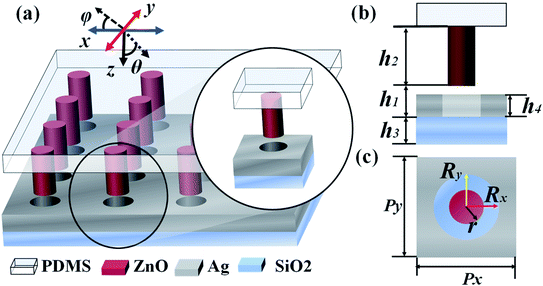 | ||
| Fig. 1 Schematic diagrams of the (a) 3D TCF-1 array, (b) cross-sectional view, and (c) top view of the TCF-1 unit cell, respectively. | ||
3. Simulation results and discussions
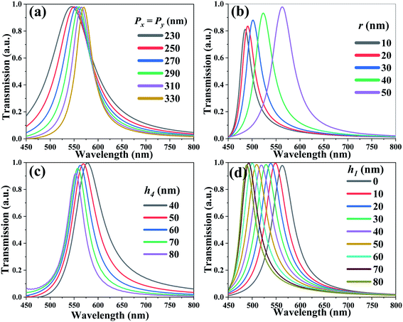
Fig. 2(a) shows the transmission spectra of TCF-1 with different period values. Herein, the values of Px and Py are changed simultaneously from 230 nm to 330 nm under normal incident TE-polarized light, while keeping h1 = 0 nm and other parameters as constants. There is a single resonance around the wavelength of 550 nm. The resonances are red-shifted by 25 nm from the wavelength of 545 nm to 570 nm by increasing the TCF period from 230 nm to 330 nm. The full width at half maximum (FWHM) of resonances is decreased from 103 nm to 41 nm, which is accompanied by an increment in the quality (Q) factors of the resonances from 5.29 to 13.90. The TCF periods are kept as Px = Py = 300 nm for further investigations considering the Q-factor and tuning range of resonance in the following discussions. Fig. 2(b) shows the transmission spectra of TCF-1 with different r values from 10 nm to 50 nm by keeping h1 = 0 nm and other parameters as constants. By increasing the r value, the resonances are red-shifted by 77 nm from the wavelength of 485 nm to 563 nm and the transmission intensities are increased from 81% to 97%. This is attributed to the intensification of SPR, which is related to the coupling field at the metal-dielectric interface. Thus, the r value is defined as 50 nm for further investigations considering the transmission intensity in the following discussions. This ultrahigh transmission intensity is attributed to the SPR due to the coupling effect of the incident electromagnetic wave at the metal–dielectric interface and LSPR related to the circular geometry of the Ag nanohole array.9Fig. 2(c) shows the transmission spectra of TCF-1 with different h4 values while keeping h1 = 0 nm and other parameters as constants. By increasing the h4 value from 40 nm to 80 nm, the resonances are blue-shifted by 26 nm from the wavelength of 578 nm to 552 nm, and the transmission intensities are decreased slightly from 100% to 92%. The FWHM values are changed from 69 nm to 44 nm accompanied by the increment of Q-factors from 8.36 to 12.55. Considering the tradeoff of the transmission intensity and Q-factor, the h4 value is defined as 60 nm for further investigations. Fig. 2(d) shows the transmission spectra of TCF-1 with different h1 values from 0 nm to 80 nm while keeping other parameters as constants. The resonances are blue-shifted by 75 nm from the wavelength of 563 nm to 488 nm. The transmission intensities are quite stable at an average of 99%, and the averaged FWHM values and Q-factors are 50 nm and 10.61, respectively. These results indicate that the h1 parameter plays a critical role in determining the optical transmission properties of TCF-1. This is because when the ZnO nanopillars are elevated (h1 > 0), the Fabry–Perot (F–P) cavity is enlarged between the ZnO nanopillars and the silica substrate surface, which is an optical resonator typically made from parallel facing mirrors in which a light field can be selectively enhanced through resonance. In this case, the patterned Ag thin-film and ZnO nanopillars can be considered as a F–P resonator. This F–P cavity is formed to generate F–P resonance, which corresponds to the reflection resonance of TCF and can be determined from16,50 | (2) |
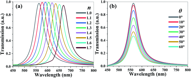
Fig. 3(a) shows the transmission spectra of TCF-1 exposed to the ambient environment with different refraction index (n) values from 1.0 to 1.7 while keeping h1 = 0 nm and other parameters as constants under normal TE-polarized incident light. By increasing the n value, the resonances are red-shifted by 106 nm from the wavelength of 562 nm to 668 nm with an averaged transmission intensity of 98%. It is because nanohole arrays confine most of the near field energies. The strong transmission resonances are highly dependent on the change of the environmental n value. The averaged FWHM values and Q-factors are 50 nm and 12.05, respectively. The sensitivity (S) of resonance to the n value can be expressed as
 | (3) |
This is because the tuning performance of TCF-1 is limited in the blue spectrum range (Fig. 2(d)), TCF-2 is proposed by enlarging the Ry value from 60 nm to 110 nm and keeping Rx as constant as 60 nm to broaden the tuning range of the resonant wavelength. Fig. 4(a) and (b) show the transmission spectra of TCF-2 with different Ry values under normal TE-polarized and TM-polarized incident lights, respectively. As shown in Fig. 4(a), the resonances of TCF-2 are significantly red-shifted by 182 nm from the wavelength of 579 nm to 761 nm in TE mode. The FWHM values under the conditions of Ry = 60 nm and Ry = 90 nm are 61 nm and 138 nm, respectively. As shown in Fig. 4(b), the resonances of TCF-2 are blue-shifted by 91 nm from the wavelength of 579 nm to 488 nm in TM mode. The FWHM values under the conditions of Ry = 60 nm and Ry = 90 nm are 59 nm and 56 nm, respectively. These results indicate that TCF-2 exhibits different shifting trends in TE and TM modes by increasing Ry. It can be observed that the variation of FWHM values is stable in TM mode compared to that in TE mode. Herein, the Ry value is defined as 90 nm for next discussions of enhancing the tuning range of resonance. It is expected that TCF-2 possesses the polarization-sensitive characteristic, because LSPR is strongly related to the feature size of the subwavelength structure. Increasing the Ry value can affect the excitation of LSPR. Meanwhile, the polarization state of incident light can also significantly affect the SPR condition, especially in asymmetrical nanoapertures.14 The influence can be understood through the propagation direction of the surface plasmons (SP) mode, which is parallel to the electric field.20 Considering that the coupling effect in and out of the SP modes occurs at the edges of the nanoholes, the resonance generated from the periodic nanohole array is aligned with the optical polarization. The variation of the Ry parameter causes the changes of LSPR and SP, and then results in the resonance shift. The transmission spectra of TCF-2 with different polarization angles (φ) from 0° (i.e., TE mode) to 90° (i.e., TM mode) under the conditions of Rx = 60 nm and Ry = 90 nm under normal incident light are shown in Fig. 4(c). The resonance at the wavelength of 680 nm can be attenuated by increasing the φ value. The transmission intensity is modified from 99% to 5% by changing the φ value from 0° to 90°. Meanwhile, the resonance at the wavelength of 504 nm is enhanced from 7% to 96%. These results indicate that TCF-2 possesses an ultrahigh color modulation depth, which can be switched between green and red colors by changing the incident polarization angle. It implies that the design of TCF-2 provides potential as a high-efficient color switch.
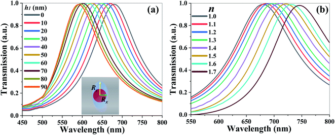
Fig. 5(a) shows the transmission spectra of TCF-2 with different h1 values from 0 nm to 90 nm under the conditions of Rx = 60 nm and Ry = 90 nm while keeping other parameters as constants under normal TE-polarized incident light. The resonances are blue-shifted by 91 nm from the wavelength of 679 nm to 590 nm by increasing the h1 value. The FWHM values are quite stable and the averaged FWHM values and Q-factors are 132 nm and 4.77, respectively. TCF-2 can be tuned to undergo color switching between yellow and red spectra by changing the h1 value. Fig. 5(b) shows the transmission spectra of TCF-2 exposed to the ambient environment with different n values from 1.0 to 1.7 under the condition of Rx = 60 nm and Ry = 90 nm under normal TE-polarized incident light. The resonances are red-shifted by 68 nm from the wavelength of 679 nm to 747 nm by increasing the n value. The sensitivity of resonance to the n value is calculated to be 97.14 nm per RIU and the corresponding FOM is 0.74.
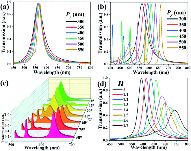
To endow the design with greater versatility and tunability, TCF-3 is proposed by extending the TCF period along the y-axis direction. TCF-3 is polarization-sensitive due to its asymmetric configuration. Fig. 6(a) and (b) show the transmission spectra of TCF-3 with different Py values from 300 nm to 550 nm while keeping Px as constant at 300 nm at the normal TE- and TM-polarized incident lights, respectively. As shown in Fig. 6(a), the resonances of TCF-3 shifted slightly in TE mode. The variation is less than 10 nm. In addition, the FWHM values become narrower from 54 nm to 29 nm, and the Q-factors increase from 10.37 to 19.58. Fig. 6(b) shows that the resonances are blue-shifted by 95 nm from the wavelength of 562 nm to 657 nm. The FWHM values are changed from 52 nm to 10 nm. TCF will generate second and third resonances when the Py is larger than 400 nm. These subordinate resonances are also red-shifted by increasing the Py value. These results indicate that the resonances of TCF-3 are affected by the periodic change along the polarized direction of incident light. Transmission spectra of TCF-3 with different polarization angles (φ) from 0° to 90° under the condition of Px = 300 nm and Py = 500 nm are depicted in Fig. 6(c). When φ equals 0°, there is a single-resonance at the wavelength of 562 nm. By increasing the φ value from 0° to 90°, the resonance becomes weaker and vanishes, and the resonances at wavelengths of 631 nm and 539 nm become more intensive, indicating that TCF-3 can operate as a light switch between red and green light simply by varying its polarization angle. Fig. 6(d) illustrates the transmission spectra of TCF-3 with different values of the environmental refraction index (n) under the condition of Px = 300 nm and Py = 500 nm under normal incident TE-polarized light. The resonances are red-shifted by 179 nm from the wavelength of 562 nm to 741 nm by increasing the n value. The transmission intensities are remarkably reduced when n is greater than 1.4. The sensitivity is 255.7 nm per RIU, which outperforms the two former designs. The optimized TCF-3 can be further used as an outstanding environmental sensor.
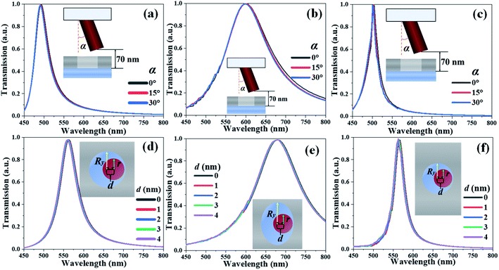
In order to demonstrate the stability of TCF-1, TCF-2, and TCF-3, the rotation angle and displacement of ZnO nanopillars along the x-axis direction are defined as α and d, respectively, to simulate the variations and disturbances during the real operation as illustrated in Fig. 7. Fig. 7(a)–(c) show the transmission spectra of TCF-1, TCF-2, and TCF-3 with different α values from 0° to 30° while keeping h1 = 70 nm under normal incident TE-polarized light, respectively. Fig. 7(d)–(f) show the transmission spectra of TCF-1, TCF-2, and TCF-3 with different d values from 0 nm to 4 nm while keeping h1 = 0 nm under normal incident TE-polarized light, respectively. The main resonances are SPR and LSPR, and F–P resonance is adopted to enable the tunability of TCFs. By changing α and d values, that does not affect the behaviors of SPR and LSPR, the geometry of F–P cavity is also fundamentally unchanged. These results indicate that the TCFs are stable by changing α and d parameters by pressing, bending, and shocking the TCF devices. TCF devices exhibit extraordinary stability under interferences and also allow the tolerance to manufacturing imperfection.
These ultrahigh transmission intensities of TCFs are attributed to the theories of SPR and LSPR due to the coupling effects of incident electromagnetic waves at the metal–dielectric interface and the geometrical parameters of circular Ag nanoholes.9,49 The conduction electron charge density and the corresponding electromagnetic field can undergo plasmon oscillations, which will propagate along the metal surface and are known as surface plasmon polaritons (SPPs),51 which can overcome the conventional diffraction limit and manipulate the propagation direction of incident light on the subwavelength scale. For periodic nanostructures in a metal thin-film, the dispersion equation of resonance for different Bloch modes of SPPs at normal incidence is widely used,2,49 which is expressed as
 | (4) |
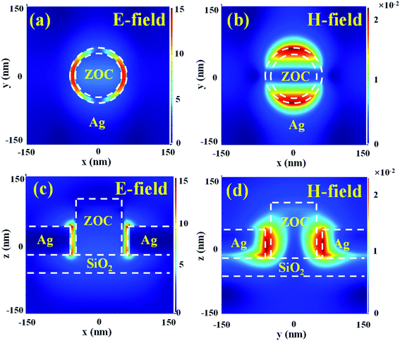 | ||
| Fig. 8 (a) and (b) Top views and (c) and (d) cross-sectional views of (a) and (c) E- and (b) and (d) H-field distributions of TCF-1 in TE mode. | ||
4. Conclusions
In conclusion, we propose three designs of TCFs by using hybrid metasurface nanostructures composed of ZnO nanopillars and Ag nanoholes to investigate the superior electromagnetic properties in the visible frequency range. TCF-1 and TCF-2 exhibit great tunability by simply changing the gap between the ZnO nanopillars and silica substrate. TCF-1 possesses the characteristics of polarization independence, angle insensitivity, and ultrahigh transmission intensity. By changing the TCF period and tailoring the circular shape into an elliptical shape, TCF-2 and TCF-3 show different tuning ranges and polarization-dependent characteristics. Moreover, TCF-3 exhibits color switching characteristics. The designs of TCFs can be designed properly to possess great tunability in the entire visible wavelength range by tailoring the geometrical parameters. TCFs exhibit remarkable stability and provide good durability and tolerance to the interference of the external environment. When TCFs are exposed to the different ambient environments, their resonances can be red-shifted by increasing the environmental refraction index. The sensitivities of TCF-1, TCF-2, and TCF-3 are 151.4 nm per RIU, 97.14 nm per RIU, and 255.7 nm per RIU, respectively. These TCFs are desirable for widespread optoelectronic applications, such as high-efficiency biosensors, pressure sensors, selective color filters, high-resolution displays, refractive index sensors, etc.Data availability
The data that support the findings of this study are available from the corresponding author upon reasonable request.Conflicts of interest
The authors declare no conflicts of interest.Acknowledgements
The authors acknowledge the financial support from the Natural Science Foundation of Basic and Applied Foundation of Guangdong Province (2021A1515012217), National Key Research and Development Program of China (2019YFA0705004), and National Natural Science Foundation of China (11690031).References
- T. W. Ebbesen, H. J. Lezec, H. F. Ghaemi, T. Thio and P. A. Wolff, Extraordinary optical transmission through sub-wavelength hole arrays, Nature, 1998, 391, 667 CrossRef CAS.
- H. F. Ghaemi, T. Thio, D. E. Grupp, T. W. Ebbesen and H. J. Lezec, Surface plasmons enhance optical transmission through subwavelength holes, Phys. Rev. B: Condens. Matter Mater. Phys., 1998, 58, 6779 CrossRef CAS.
- A. A. Yanil, M. Huang, O. Kamohara, A. Artar, T. W. Geisbert, J. H. Connor and H. Altug, An Optofluidic-Nanoplasmonic Biosensor for Direct Detection of Live Viruses from Biological Media, Nano Lett., 2010, 12, 4962 Search PubMed.
- T. Xu, H. Shi, Y. Wu, A. F. Kaplan, J. G. Ok and L. Guo, Structural Colors: From Plasmonic to Carbon Nanostructures, Small, 2011, 22, 3128 CrossRef PubMed.
- N. Pinton, J. Grant, S. Collins and D. R. S. Cumming, Exploitation of Magnetic Dipole Resonances in Metal-Insulator-Metal Plasmonic Nanostructures to Selectively Filter Visible Light, ACS Photonics, 2018, 5, 1250 CrossRef CAS.
- C. David and J. Christensen, Extraordinary optical transmission through nonlocal holey metal films, Appl. Phys. Lett., 2017, 110, 2611110 Search PubMed.
- X. Hu, D. Zheng and Y.-S. Lin, Actively Tunable Terahertz Metamaterial with Single-Band and Dual-Band Switching Characteristic, Appl. Phys. A: Mater. Sci. Process., 2020, 126, 110 CrossRef CAS.
- Y. Ma, B. Dong and C. Lee, Progress of infrared guided-wave nanophotonic sensors and devices, Nano Convergence, 2020, 7, 12 CrossRef CAS PubMed.
- L. M. Moreno, F. J. G. Vidal, H. J. Lezec, K. M. Pellerin, T. Thio, J. B. Pendry and T. W. Ebbesen, Theory of extraordinary optical transmission through subwavelength hole arrays, Phys. Rev. Lett., 2001, 86, 1114 CrossRef PubMed.
- H. A. Bethe, Theory of diffraction by small holes, Phys. Rev., 1944, 66, 163 CrossRef.
- Y.-S. Lin and C. Lee, Tuning Characteristics of Mirrorlike T-Shape Terahertz Metamaterial Using Out-of-Plane Actuated Cantilevers, Appl. Phys. Lett., 2014, 104(25), 251914 CrossRef.
- W. L. Barnes, A. Dereux and T. W. Ebbesen, Surface plasmon subwavelength optics, Nature, 2003, 424, 824 CrossRef CAS PubMed.
- Q. Song, Y. Miao, Q. Yan, M. Xu, G. Wang, X. Gao and X. Dong, High-transmission rotation-angle-dependent plasmonic color filter, Optik, 2021, 242, 167099 CrossRef CAS.
- J. Park, H. Lee, A. Gliserin, K. Kim and S. Kim, Spectral Shifting in Extraordinary Optical Transmission by Polarization-Dependent Surface Plasmon Coupling, Plasmonics, 2020, 15, 489 CrossRef.
- J. Braun, B. Gompf, G. Kobiela and M. Dressel, How Holes Can Obscure the View: Suppressed Transmission through an Ultrathin Metal Film by a Subwavelength Hole Array, Phys. Rev. Lett., 2009, 57, 70550 Search PubMed.
- R. Rajasekharan, E. Balaur, A. Minovich, S. Collins, T. D. James, A. D. Assl, K. Ganesan, S. T. Hanic, S. Kandasamy, E. Skafidas, D. N. Neshev, P. Mulvaney, A. Roberts and S. Prawer, Filling schemes at submicron scale: Development of submicron sized plasmonic colour filters, Sci. Rep., 2014, 4, 6435 CrossRef CAS PubMed.
- Z. Chen, P. Li, S. Zhang, Y. Chen, P. Liu and H. Duan, Enhanced extraordinary optical transmission and refractive-index sensing sensitivity in tapered plasmonic nanohole arrays, Nanotechnology, 2021, 30, 335201 CrossRef PubMed.
- J. Liu, M. He, X. Zhai, L. Wang, S. Wen, L. Chen, Z. Shao, Q. Wan, B. Zou and J. Yao, Tailoring optical transmission via the arrangement of compound subwavelength hole arrays, Opt. Express, 2009, 17, 1859 CrossRef CAS PubMed.
- V. R. Shrestha, S. S. Lee, E. S. Kim and D. Y. Choi, Aluminum Plasmonics Based Highly Transmissive Polarization-Independent Subtractive Color Filters Exploiting a Nanopatch Array, Nano Lett., 2014, 14, 6672 CrossRef CAS PubMed.
- R. Gordon, A. G. Brolo, A. Mckinnon, A. Rajora, B. Leathem and K. L. Kavanagh, Strong Polarization in the Optical Transmission through Elliptical Nanohole Arrays, Phys. Rev. Lett., 2004, 98, 037401 CrossRef PubMed.
- Y. K. R. Wu, A. E. Hollowell, C. Zhang and L. Guo, Angle-Insensitive Structural Colours based on Metallic Nanocavities and Coloured Pixels beyond the Diffraction Limit, Sci. Rep., 2013, 3, 1194 CrossRef PubMed.
- D. Fleischman, L. A. Sweatlock, H. Murakami and H. Atwater, Hyper-selective plasmonic color filters, Opt. Express, 2017, 25, 27386 CrossRef CAS PubMed.
- B. Zeng, Y. Gao and F. J. Bartoli, Ultrathin Nanostructured Metals for Highly Transmissive Plasmonic Subtractive Color Filters, Sci. Rep., 2013, 3, 2840 CrossRef PubMed.
- Z. Zhang, J. Luo, M. Song and H. Yu, Polarization filtering and phase controlling metasurfaces based on a metal-insulator-metal grating, Plasmonics, 2017, 12, 1797 CrossRef CAS.
- S. Wu, Z. Zhang, Y. Zhang, K. Zhang, L. Zhou, X. Zhang and Y. Zhu, Enhanced Rotation of the Polarization of a Light Beam Transmitted through a Silver Film with an Array of Perforated S-Shaped holes, Phys. Rev. Lett., 2013, 110, 207401 CrossRef PubMed.
- T. D. James, P. Mulvaney and A. Roberts, The Plasmonic Pixel: Large Area, Wide Gamut Color Reproduction Using Aluminum Nanostructures, Nano Lett., 2016, 16, 3817 CrossRef CAS PubMed.
- M. Jalali, Y. Yu, K. Xu, R. Ng and Z. Dong, Stacking of colors in exfoliable plasmonic superlattices, Nanoscale, 2016, 8, 18228 RSC.
- Y.-S. Lin and W. Chen, Perfect meta-absorber by using pod-like nanostructures with ultra-broadband, omnidirectional, and polarization-independent characteristics, Sci. Rep., 2018, 8, 7150 CrossRef PubMed.
- A. Shaukat, F. Noble and K. M. Arif, Nanostructured Color Filters: A Review of Recent Developments, Nanomaterials, 2020, 10, 1554 CrossRef CAS PubMed.
- Y. Qin, J. He, F. Yang, Z. Zhang, Z. Yuan and M. Wu, Extraordinary optical transmission properties of a novel Bi-layered plasmonic nanostructure array, Optik, 2018, 174, 684 CrossRef CAS.
- S. Tajik and Z. Atlasbaf, Investigating extraordinary optical transmission and sensing performance through periodic bilayer mafneto-plasmonic structure, J. Appl. Phys., 2020, 127, 023102 CrossRef CAS.
- Z. Nasehi and N. Nozhat, Liquid crystal based tunable plasmonic subtractive color filters, Opt. Commun., 2019, 455, 96 CrossRef.
- Q. He, N. Youngblood, Z. Cheng, X. Miao and H. Bhaskaran, Dynamically tunable transmission color filters using ultra-thin phase change materials, Opt. Express, 2020, 28, 39841 CrossRef CAS PubMed.
- E. Balaur, C. Sadatnajafi, S. Kou, J. Lin and N. B. B. Abbey, Continuously Tunable, Polarization Controlled, Colour Palette Produced from Nanoscale Plasmonic Pixels, Sci. Rep., 2016, 6, 28062 CrossRef CAS PubMed.
- D. Zheng and Y.-S. Lin, Tunable Dual-Split-Disk Resonator with Electromagnetically Induced Transparency Characteristic, Adv. Mater. Technol., 2020, 5, 202000584 Search PubMed.
- Y.-S. Lin, J. Dai, Z. Zeng and B.-R. Yang, Metasurface Color Filters Using Aluminum and Lithium Niobate Configurations, Nanoscale Res. Lett., 2020, 15, 77 CrossRef CAS PubMed.
- Y.-S. Lin and Z. Xu, Reconfigurable metamaterials for optoelectronic applications, Int. J. Optomechatronics, 2020, 14, 78 CrossRef.
- R. Xu and Y.-S. Lin, Tunable Infrared Metamaterial Emitter for Gas Sensing Application, Nanomaterials, 2020, 10, 1442 CrossRef CAS PubMed.
- A. W. Hanna, A. E. Aziza, A. S. Aida and K. B. Inas, Zinc Oxide nano-rods: Challenges for Glucose Biosensors, Egypt. J. Chem., 2021, 64, 1219 Search PubMed.
- S. H. Liao, H. J. Jhuo, P. H. Yeh, Y. S. Cheng, Y. L. Li, Y. H. Lee, S. Sharma and S. Chen, Single Junction Inverted Polymer Solar Cell Reaching Power Conversion Efficiency 10.31% by Employing Dual-Dopled Zinc Oxide Nano-Film as Cathode Interlayer, Sci. Rep., 2014, 4, 6813 CrossRef CAS PubMed.
- E. A. S. Dimapilis, C. S. Hsu, R. M. O. Mendoza and M. C. Lu, Zinc oxide nanoparticles for water disinfection, Sustainable Environ. Res., 2018, 28, 47 CrossRef CAS.
- X. Xu, R. Xu and Y.-S. Lin, A voltage-controllable VO2 based metamaterial perfect absorber for CO2 gas sensing application, Nanoscale, 2022, 14, 2722–2728 RSC.
- Y. Zhang, P. Lin and Y.-S. Lin, Tunable Split-Disk Metamaterial Absorber for Sensing Application, Nanomaterials, 2021, 11(3), 598 CrossRef CAS PubMed.
- R. Xu, X. Xu, B.-R. Yang, X. Gui, Z. Qin and Y.-S. Lin, Actively Logical Modulation of MEMS-Based Terahertz Metamaterial, Photonics Res., 2021, 9(7), 1409–1415 CrossRef.
- Y. Mo, J. Zhong and Y.-S. Lin, Tunable Chevron-Shaped Infrared Metamaterial, Mater. Lett., 2020, 263, 127291 CrossRef CAS.
- Y.-S. Lin, K. Yan, D. Yao and Y. Yu, Investigation of electromagnetic response of terahertz metamaterial by using split-disk resonator, Opt. Laser Technol., 2019, 111, 509–514 CrossRef CAS.
- H. Ou, F. Lu, Y. Liao, F. Zhu and Y.-S. Lin, Tunable Terahertz Metamaterial for High-Efficiency Switch Application, Results Phys., 2020, 16, 102897 CrossRef.
- R. Xu, X. Xu and Y.-S. Lin, Electrothermally Tunable Terahertz Cross-Shaped Metamaterial for Opto-Logic Operation Characteristic, iScience, 2022, 25(4), 104072 CrossRef CAS PubMed.
- R. Xu and Y.-S. Lin, Flexible and Controllable Metadevice Using Self-Assembly MEMS Actuator, Nano Lett., 2021, 21(7), 3205–3210 CrossRef CAS PubMed.
- N. Ismail, C. C. Kores, D. Geskus and M. Pollnau, Fabry-Perot resonator: spectral line shapes, generic and related airy distributions, linewidths, finesses, and performance at low or frequency-dependent reflectivity, Opt. Express, 2016, 24, 16366 CrossRef PubMed.
- Y. Eksioglu, A. E. Cetin and J. Petracek, Optical Response of Plasmonic Nanohole Arrays: Comparison of Square and Hexagonal Lattices, Plasmonics, 2016, 11, 851 CrossRef CAS.
- G. D. Qing, S. Krishnan, P. Z. Li, V. D. Hilmi, H. K. Chan and W. S. Xiao, A two-dimensional nanopatterned thin metallic transparent conductor with high transparency from the ultraviolet to infrared, Appl. Phys. Lett., 2012, 101, 181112 CrossRef.
Footnote |
| † These authors contributed equally. |
| This journal is © The Royal Society of Chemistry 2022 |

