High-yield cell ordering and deterministic cell-in-droplet encapsulation using Dean flow in a curved microchannel†
Evelien W. M.
Kemna
*a,
Rogier M.
Schoeman
a,
Floor
Wolbers
a,
Istvan
Vermes
a,
David A.
Weitz
b and
Albert
van den Berg
a
aBIOS, Lab on a Chip group, MESA+ Institute for Nanotechnology, University of Twente, P.O. Box 217, 7500 AE, Enschede, The Netherlands. E-mail: e.w.m.kemna@ewi.utwente.nl; Fax: +31 (0)53 489 3595
bDepartment of Physics and School of Engineering and Applied Sciences, Harvard University, Cambridge, MA, USA
First published on 26th April 2012
Abstract
In this article high-yield (77%) and high-speed (2700 cells s−1) single cell droplet encapsulation is described using a Dean-coupled inertial ordering of cells in a simple curved continuous microchannel. By introducing the Dean force, the particles will order to one equilibrium position after travelling less than 1 cm. We use a planar curved microchannel structure in PDMS to spatially order two types of myeloid leukemic cells (HL60 and K562 cells), enabling deterministic single cell encapsulation in picolitre drops. An efficiency of up to 77% was reached, overcoming the limitations imposed by Poisson statistics for random cell loading, which yields only 37% of drops containing a single cell. Furthermore, we confirm that > 90% of the cells remain viable. The simple planar structure and high throughput provided by this passive microfluidic approach makes it attractive for implementation in lab on a chip (LOC) devices for single cell applications using droplet-based platforms.
1 Introduction
Droplet-based microfluidic systems have been used for various biotechnology research applications,1–3 such as cell-based assays,4 polymerase chain reactions,5 proteome analysis6 and cell printing technologies,7 and have become a standard platform for high-throughput single-cell experimentation and analysis.8 Moreover, droplets facilitate high-throughput single cell analysis.9 Encapsulation of single cells within picolitre-sized droplets enable quantitative studies of large populations of single cells.10,11 The droplets serve as microvessels which entrap the secretion products of the individual cells and prevent mixing with other cells. In addition, the uptake of trace chemicals can be probed due to their depletion within the confined droplet. Using microfluidic devices, monodisperse droplets can be generated, merged and sorted at kilohertz rates, enabling high-throughput single cell screening.12 However, the platform suffers from one fundamental limitation: the variability in the number of cells per droplet.13 Typically, cells are loaded into the droplets by diluting suspensions of the cells and randomly encapsulating them into the droplets. The distribution is thus dictated by Poisson statistics:| P(λ;k) = λkexp(−λ)/k! | (1) |
We overcome these drawbacks with a fast, easy and novel approach to deterministically encapsulate single cells within droplets using inertial ordering in a curved microchannel. The curvature introduces a second force, the Dean force, which causes the particles to focus into a single equilibrium position. The device shows a wider dynamic range with regards to the particle size and number of equilibrium positions. Moreover, it possesses a small footprint, making it easy to implement in microfluidic LOC devices. Curved microchannels also show faster cell ordering than straight channels.18 Inertial ordering of particles in curved microchannels has been used in sorting and filtration applications19–22 but not for single-cell encapsulation. The microfluidic chip consists of a curved microchannel which combines inertial ordering with Dean forces to evenly space the cells. By matching the periodicity of the cell flow with the droplet generation, we increase the efficiency of single-cell encapsulation. This deterministic encapsulation method reduces the number of empty and multi-cell droplets while increasing the number of droplets which contain a single cell.
1.1 Theoretical background
Fluid flowing through a straight rectangular microchannel experiences a primary Poiseuille flow which has a parabolic velocity profile. This parabolic velocity results in a fluidic shear-gradient-induced inertial lift force (FIL). This causes the particles in the flow to move away from the centerline. However, as the particles move towards the walls of the microchannel, a wall-induced inertial lift force (FWL) pushes the particles away from the wall, due to the asymmetric wake induced around the particles. This causes FWL to increase as the particles approach the wall. As FIL and FWL are opposing lift forces, which vary in magnitude across the cross-section of the microchannel, the particles are forced to occupy positions where the two forces cancel. Hence, in a straight rectangular microchannel, there are up to four equilibrium positions present,23–25 depending on the channel dimensions and volume fraction.10,26In a continuous curved rectangular microchannel, there is a secondary flow due to the difference between the downstream velocity of the fluid in the center and that near the wall. Thus, fluid elements have a larger inertia in the center of the microchannel than near the walls. This produces a pressure gradient in the radial direction of the microchannel, as the fluid tends to flow outward around the curve, leading to the formation of two counter rotating vortices at the top and bottom halves of the microchannel. The magnitude of these secondary flows is quantified by the Dean number.19,22
 | (2) |
| UD = 1.8 × 10⁻⁴ × De1.63 | (3) |
The Dean flows are capable of applying a drag force on the particles present in the fluid. The maximum value of this drag force (FD) can be estimated by Stokes drag:27,28
| FD = 3 × π × μ × UD × ap = 5.4 × 10⁻⁴ × π × μ × De1.63 × ap | (4) |

| (5) |
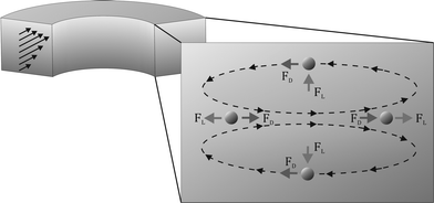 | ||
| Fig. 1 Schematic illustration of a continuous curved rectangular microchannel in which both the Dean force (FD) and lift force (FL) are present as well as the directions of their applied force on the particles, resulting in a single equilibrium position at the inner wall of the microchannel, where both forces operate in opposite directions. | ||
The channel length (LD, m), required for all the particles to travel to an equilibrium position on the inside of the microchannel wall is given by Di Carlo et al.:23
 | (6) |
1.2 Particle spacing
As stated, in a straight channel the number of equilibrium positions for the particles can be determined by adjusting the channel dimensions and the volume fraction of particles in the solution:26 | (7) |
The longitudinal distance, l, between the particles on the same side of the channel does not depend on the volume fraction. By adjusting the flow rate of the fluid, the channel dimensions, the volume fraction and the particle diameter, it is possible to align the particles at a single equilibrium position, all with similar longitudinal distances. This enables the encapsulation of single particles within droplets in a straight channel. Moreover, it is likely that a similar relationship between Rep and l pertains to a continuous curved rectangular microchannel. Similarly, there should be a relationship between the volume fraction and the number of equilibrium positions.
2 Materials and Methods
2.1 Microfluidic chip design and fabrication
The microfluidic chip consists of a 5-loop curved microchannel, with one inlet for the cell suspension and one inlet for the oil. The curved microchannel is 50 μm wide and 29 μm high, with 100 μm spacing between the two successive loops. The initial radius of the spiral is 1500 μm and the total length is 7.2 cm. Three different types of droplet generators were tested, referred to as type A–C.A silicon master design was drawn in Clewin (version 4.0.1) and fabricated using standard UV-lithography. SU-8 2–25 (Microchem, Berlin, Germany) was spun on the silicon master with a thickness of 29 μm. The chip was made in PDMS (Sylgard 184, Dow Corning, Midland, MI, USA). The curing and base agent were mixed at a ratio of 1![[thin space (1/6-em)]](https://www.rsc.org/images/entities/char_2009.gif) :
:![[thin space (1/6-em)]](https://www.rsc.org/images/entities/char_2009.gif) 10 and degassed. PDMS was poured onto a silicon wafer, degassed, and cured at 60 °C for 24 h. After curing, in- and outlets were punched using a dispensing tip (Nordson EFD, Maastricht, the Netherlands, ID 1.36 mm and OD 1.65 mm). Subsequently, the PDMS was sealed to a microscope slide (VWR, Leuven, Belgium) using an oxygen plasma (Harrick PDC-001, NY, USA). After sealing, the chip was heated at 60 °C for a minimum of 30 min. Before use, Aquapel (Vulcavite, the Netherlands) was introduced into the channels to ensure hydrophobic channel walls.
10 and degassed. PDMS was poured onto a silicon wafer, degassed, and cured at 60 °C for 24 h. After curing, in- and outlets were punched using a dispensing tip (Nordson EFD, Maastricht, the Netherlands, ID 1.36 mm and OD 1.65 mm). Subsequently, the PDMS was sealed to a microscope slide (VWR, Leuven, Belgium) using an oxygen plasma (Harrick PDC-001, NY, USA). After sealing, the chip was heated at 60 °C for a minimum of 30 min. Before use, Aquapel (Vulcavite, the Netherlands) was introduced into the channels to ensure hydrophobic channel walls.
2.2 Materials
Two types of myeloid leukemic cells where used: HL60 (human promyelocytic leukemic cells) and K562 (human erythromyeloblastoid leukemic cells). Both cell types were grown in an RPMI medium (Invitrogen, Grand Island, NY, USA), supplemented with 10% (v/v) fetal bovine serum (FBS; Invitrogen), 100 U ml¬1 penicillin (Invitrogen), 100 μg ml−1 streptomycin (Invitrogen) and 2 mM L-glutamine (Invitrogen) (= RPMI+ medium). Cell cultures were sustained in a 5% CO2 humidified atmosphere at 37 °C. Cell cultures were split every 3–4 days at a ratio of 1![[thin space (1/6-em)]](https://www.rsc.org/images/entities/char_2009.gif) :
:![[thin space (1/6-em)]](https://www.rsc.org/images/entities/char_2009.gif) 10. In the experiments, the cells were suspended at the desired volume fraction, ranging from 1 to 2.2%, in an RPMI+ medium prior to use. Polystyrene beads (Polysciences Inc, Germany) with a diameter of 10 μm were used for the control experiments. For the continuous phase, FC-40 (3M, St. Paul, MN, USA) was used with a 1% (w/w) oil-phase surfactant.
10. In the experiments, the cells were suspended at the desired volume fraction, ranging from 1 to 2.2%, in an RPMI+ medium prior to use. Polystyrene beads (Polysciences Inc, Germany) with a diameter of 10 μm were used for the control experiments. For the continuous phase, FC-40 (3M, St. Paul, MN, USA) was used with a 1% (w/w) oil-phase surfactant.
2.3 Experimental set-up
Cell suspensions and oil were separately introduced into the microfluidic chip using two 3 ml plastic syringes (BD, Breda, the Netherlands), and were connected to the two inlets with PEEK tubing (Vici, Schenkon, Switzerland, ID 0.5 mm and OD 1.59 mm). PEEK tubing was also connected to the outlet of the device and routed into a collection tube. The flow was driven at a constant volume rate by a syringe pump (neMESYS dosing units, Cetoni GmbH, Germany). A magnetic stirrer bar was inserted into the cell suspension containing the syringe to prevent the suspension from settling during the injection. The flow rate of the continuous phase was 30–43 μL min−1 and the aqueous flow rate, containing the cells, was set to 10–20 μL min−1.The microfluidic chip was mounted onto the X–Y–Z translation stage of an inverted wide fluorescence microscope (Leica DM IRM, Leica Microsystems, Wetzlar, GmbH, Germany). In addition, a computer-controlled high-speed camera (Photron SA-3, West Wycombe, United Kingdom) was mounted onto the microscope for image recording, using the accompanied Photron software (Photron Fastcam Viewer). Illumination was supplied by a fiber optic illuminator (Leica KL 1500 LCD).
2.4 Image acquisition and analysis
Videos and images of the cell ordering in the curved microchannel and subsequent cell encapsulation were captured using the high-speed camera, at a frame rate of 3000–18![[thin space (1/6-em)]](https://www.rsc.org/images/entities/char_2009.gif) 181 frames per second and a shutter time of 5–30 μs. All the videos and images captured were analyzed with the image-processing program ImageJ (National Institute of Health, MD, USA). To determine the encapsulation efficiency, the number of droplets containing 0, 1, or more cells was divided by the total number of droplets generated.
181 frames per second and a shutter time of 5–30 μs. All the videos and images captured were analyzed with the image-processing program ImageJ (National Institute of Health, MD, USA). To determine the encapsulation efficiency, the number of droplets containing 0, 1, or more cells was divided by the total number of droplets generated.
3 Results and discussion
First, we characterized the relevant forces present in the microfluidic chip which cause the cell ordering.3.1 Characterization of the microfluidic chip
The microfluidic chip consists of 5 loops with a total length of 7.2 cm, followed by an encapsulation part (Fig. 2). Using eqn (2)–(5), the microfluidic chip was characterized for its cell ordering capacity.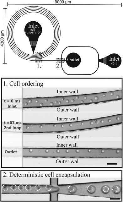 | ||
| Fig. 2 Schematic drawing of the microfluidic chip consisting of a curved microchannel followed by an encapsulation part. The pictures are of the cell ordering and subsequent encapsulation. Scale bars are 50 μm. | ||
Table 1 shows how the flow rate (Qf) and the channel dimensions influence the Reynolds number (Re), the Reynolds particle number (Rep), the Dean number (De), and the apparent Dean (FD) and lift forces (FL) using 13 ± 1.6 μm HL60 cells (n = 25) or 13.8 ± 2.2 μm K562 cells (n = 25).
| Width × height | 50 × 29 (μm) | ||
|---|---|---|---|
| Q f (μL min−1) | 10 | 15 | 20 |
| Re | 4.2 | 6.3 | 8.4 |
| Rep | 0.53 | 0.79 | 1.06 |
| De | 0.46 | 0.7 | 0.93 |
| F L (N) | 5.6 × 10⁻¹⁰ | 1.3 × 10⁻⁹ | 2.2 × 10⁻⁹ |
| F D (N) | 6.4 × 10⁻¹² | 1.2 × 10⁻¹¹ | 2 × 10⁻¹¹ |
The Dean forces acting on the 13 μm cells at the three flow rates are less than the corresponding lift forces. Thus, the lift forces dominate, which predicts that ordering will occur and the cells will focus along the one equilibrium position at the inner wall, as illustrated in Fig. 1.
3.2 Cell ordering
Cell ordering was observed in the continuous curved microchannel, when the flow rates approached 15 μL min−1 or higher. The observed cell ordering is classified as two types of self-organization. Firstly, the cells were focused in one streamline along the inner wall (Fig. 2). Secondly, the cells were arranged in an array that alternated not in the z-direction18 but instead in the x–y direction (Fig. 3). These self-organization patterns shared three distinctive characteristics for cell ordering in straight microchannels:10,18 (1) the cells moved as a group in the direction of the flow, (2) the cells were separated from their nearest neighbour by an uniform spacing and (3) the cells were always found near a channel wall. | ||
| Fig. 3 Double equilibrium position of the HL60 cells observed in the focal plane, in the second loop of the curved microchannel. Insert shows the longitudinal distance measurement, L1, of the cells at the single equilibrium position at the inner wall and L2 for the longitudinal distance of the cells in the alternating pattern. Scale bar is 50 μm. | ||
Cell ordering was observed in the second loop in the direction of the flow (longitudinal) after 9400 μm, corresponding to 67 ms, when flowed at a rate of 15 μL min−1, as shown in Fig. 2. Thus, curved microchannels cause faster ordering towards the predicted equilibrium position than straight microchannels.18 The observed channel length required for ordering (∼ 0.9 cm) is in the order of the calculated length (∼ 0.6 cm) using eqn (6).
The shorter channel length required for ordering, offers a critical advantage because fluidic resistance decreases and hence, decreases the pressure and power required to drive the flow. In fact, it seems that fluidic resistance is the limiting factor for increasing the throughput of ordering because high pressure leads to leakage at the fluid inlets.18 Therefore, our system is more robust for single cell encapsulation when compared to straight channels devices.
Additionally, channel clogging never occurred in the required first cm of the device, making this system more robust for particle ordering when compared to the necessary several cms in a straight channel.
The longitudinal distance, between adjacent cells on the same side of the channel (Fig. 3, insert L1), at flow rates of 15 μL min−1 was 52 ± 6 μm. This flow rate corresponded to velocities of 14 ± 0.4 cm s−1. Furthermore, Fig. 4 shows that when the flow rate increased from 15 to 50 μL min−1 (Rep = 0.8–2.7), the longitudinal distance was not significantly influenced. However, this is mainly due to the large standard deviations in the longitudinal distance between the cells. The longitudinal distance for the cells varied from 39 to 52 μm, corresponding to ∼ 4 times the cell diameter. This observation has not been previously reported for a continuously symmetrically curved microchannel.24 For comparison, we also determined the longitudinal distance (L1) of 10 μm beads for different flow rates. The average longitudinal distance between the beads was lower than that between adjacent cells, as shown in Fig. 4. However this decrease is not significant. Moreover, the standard deviation of the distance between the beads was lower than that between the cells. One possible explanation is that the coefficient of variation (CV) for both HL60 and K562 cells is higher (n = 25, CV 13% and 16%) compared to that of the beads (n = 25, CV 10%). In addition, cell ordering into an alternating pattern across the channel was observed in the focal plane of the second loop at 15 μL min−1. Hence, the longitudinal distance between the particles was reduced to 28.3 ± 3.3 μm (Fig. 3, insert L2). Here, the velocity is similar to that used to obtain the one-equilibrium position. The microfluidic device was capable of ordering particles with dimensions down to 6 μm, demonstrating the dynamic range, which has not been seen in straight channels.10,18 Moreover, no difference in the ordering capability between the two different cell types was observed.
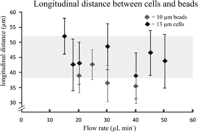 | ||
| Fig. 4 Longitudinal distance between cells (HL60) at different flow rates and 10 μm beads (error bars represents 1 SD) (n = 25). | ||
One of the key factors causing the double-equilibrium position in the continuous curved microchannel was the volume fraction of the suspended cells. When the volume fraction reached 2.2%, an increasing number of double-equilibrium positions was observed, suggesting a similar relationship for curved microchannels as well as straight microchannels, as described in eqn (7). In conclusion, the volume fraction provides increased control with regards to a single or double equilibrium position, in contrast to straight channels where there is always a minimum of two equilibrium positions. Furthermore, the longitudinal spacing (L1) between the particles remains unaffected when changing the volume fraction between 1.7–2.2%. Additionally, due to particle interaction, increasing the volume fraction above 2.2% will decrease the distance between the particles. However, no ordering occurs at that point.
Moreover, increasing the flow rate from 15 to 50 μl min−1 did not influence the double equilibrium position. Finally, it has been suggested by Di Carlo et al.24,25 that an inertial force ratio, Rf = ap2*R / x3, is useful for predicting particle behaviour. Here, Rf describes the order of magnitude scaling between FL and FD. It was proposed that the equilibrium positions can be modified by the secondary flow at an intermediate Rf > 0.04 (Rf = 9.6). This could lead to interesting new ordering modes, as shown here, for a continuous curved microchannel. However, we still lack a complete explanation as to why this geometry, in combination with specific volume fractions of cells, caused the single equilibrium position of the cells in continuous curved microchannels to shift to two equilibrium positions.
Overall, the single equilibrium position is most stable and prominent during the experiments when using the appropriate volume fraction of cells (1.7%) and flow rate (15 μL min−1).
3.3 Cell encapsulation
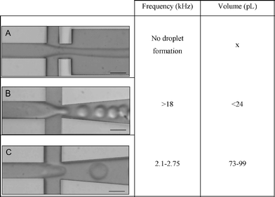
The curved microchannel presented here generates a cell train with a precise longitudinal spacing. This is critical for controlling the loading of single cells into the droplets. To demonstrate this, we analysed the use of three different flow-focusing geometries (Table 2) for emulsifying concentrated suspensions of HL60 or K562 cells immediately after they traversed the curved microchannel. The longitudinal distance and the corresponding velocity at one equilibrium position resulted in a cell frequency of 2700 cells s−1.
|
Type A, a regular junction, showed no droplet formation at the flow rates of interest. The second design, type B, generated droplets at 18 kHz or higher, which was too high compared to the cell frequency (2700 cells s−1). Type C generated 73–99 pL droplets between 2.1–2.75 kHz. Hence, encapsulation experiments were performed with this type.
To ensure that the droplets contained only a single cell, we adjusted the oil flow to generate droplets with a frequency comparable to, or higher than, the frequency of the cells. Thus, the oil flow rate was set at 43 μL min−1. This generated 73 pL droplets at 2.7 kHz (see ESI video 1†).
We compared the cell encapsulation efficiency with that determined by a Poisson distribution in Fig. 5. The percentage of droplets containing single cells is significantly increased using the curved microchannel for cell ordering. The efficiency of encapsulating single cells approaches 80% and the percentage of droplets containing multiple cells or no cells remains very low. A Poisson distribution yields a similar percentage of droplets containing multiple cells but far more empty droplets. The efficiency of producing droplets with single cells using a Poisson distribution is around 30%. When using the curved microchannel this efficiency is almost three times higher.
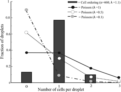 | ||
| Fig. 5 Deterministic cell encapsulation showing cell ordering vs. Poisson distributed cell encapsulation | ||
The cell volume fraction is an important factor for controlling the efficiency of single-cell encapsulation. Long empty spaces between the cells are undesirable, requiring values greater than 1.5% in this device. By contrast, when the volume fraction is greater than 2%, cell ordering is disturbed due to cell–cell interactions and double equilibrium positions. This can be compensated to some extent by adjusting the droplet frequency. The experimentally determined volume fraction corresponds to λ = 1.1, which may explain the percentage of droplets containing two cells. However, decreasing λ results in an increased percentage of empty droplets.
Finally, the viability of the encapsulated cells was examined. The cells were stained with calcein AM and propidium iodide to determine cell viability and membrane integrity after encapsulation. The results showed that 92% of the cells retained their membrane integrity, compared with 97% in the control samples (data not shown).
The device presented here is able to provide up to 80% of the droplets containing only a single cell. Furthermore, when using the curved microchannel the ratio between the droplets containing one and two cells is 8![[thin space (1/6-em)]](https://www.rsc.org/images/entities/char_2009.gif) :
:![[thin space (1/6-em)]](https://www.rsc.org/images/entities/char_2009.gif) 1. To establish this ratio with a Poisson distribution, the cell suspension would have to be diluted to a λ of 0.25, which would lead to less than 20% of the droplets containing single cells, a decrease of nearly a factor of four. However, due to the large standard deviation in the longitudinal spacing between the cells, it is not possible to obtain a 100% encapsulation efficiency of single cells using this approach. Future work will focus on real deterministic single cell encapsulation within droplets, such as coupling this device to an integrated impedance analyser, which might result in 100% efficiency.
1. To establish this ratio with a Poisson distribution, the cell suspension would have to be diluted to a λ of 0.25, which would lead to less than 20% of the droplets containing single cells, a decrease of nearly a factor of four. However, due to the large standard deviation in the longitudinal spacing between the cells, it is not possible to obtain a 100% encapsulation efficiency of single cells using this approach. Future work will focus on real deterministic single cell encapsulation within droplets, such as coupling this device to an integrated impedance analyser, which might result in 100% efficiency.
4 Concluding remarks
In this work, we discuss a microfluidic device with a curved microchannel which is capable of cell ordering based on Dean forces. Calculations were performed to characterize and understand the forces influencing the cell ordering in the curved microchannel. Cell ordering was studied experimentally and two equilibrium positions were observed after travelling the curved microchannel for less than 1 cm. Subsequently, single cell encapsulation was successfully demonstrated by achieving a single cell encapsulation efficiency approaching 80%, whilst retaining a low volume of multiple and empty droplets. Furthermore, cell viability was maintained.This microfluidic chip can perform efficient encapsulation of single cells on a relatively small device footprint (∼ 0.4 cm2), which offers easy integration into droplet-based microfluidic LOCs having low sample availability. Moreover, the short ordering distance decreases the fluidic resistance and thus lowers the required pressure and power to drive the flow, which minimizes costs. Additionally, the microfluidic design is versatile and capable of ordering particles over a wide dynamic range (6–13 μm). This device is particularly suitable for use with small sample volumes. Thus, it can contribute to a variety of biomedical or manufacturing applications that involve rapid, low-cost, continuous encapsulation of single cells.
Acknowledgements
The work at Harvard was supported by the NSF (DMR-1006546) and the Harvard MRSEC (DMR-0820484). The authors thank Lloyd Ung at Harvard for technical support and Ralph Sperling at Harvard for supplying the oil-phase surfactant. Financial support from the European Research Council ERC (eLab4life project), NWO - Netherlands Organization for Scientific Research (NanoNextNL) and the technical assistance of J. G. Bomer and P.M. ter Braak are gratefully acknowledged. The authors declare no conflict of interest.References
- S. Y. Teh et al., Droplet microfluidics, Lab Chip, 2008, 8(2), 198–220 RSC
.
- A. R. Wheeler et al., Digital microfluidics for cell-based assays, Lab Chip, 2008, 8(4), 519–526 RSC
.
- G. M. Whitesides, The origins and the future of microfluidics, Nature, 2006, 442(7101), 368–373 CrossRef CAS
.
- G. Gelinck et al., Charge transport in high-performance ink-jet printed single-droplet organic transistors based on a silylethynyl substituted pentacene/insulating polymer blend, Org. Electron., 2011, 12(8), 1319–1327 CrossRef CAS
.
- S. H. Chao et al., Real-time PCR of single bacterial cells on an array of adhering droplets, Lab Chip, 2011, 11(13), 2276–2281 RSC
.
- A. R. Wheeler, Digital microfluidics with in-line sample purification for proteomics analyses with MALDI-MS, Anal. Chem., 2005, 77(2), 534–540 CrossRef CAS
.
- P. Koltay et al., Inkjet-like printing of single-cells, Lab Chip, 2011, 11(14), 2447–2454 RSC
.
- G. M. Whitesides, What comes next?, Lab Chip, 2011, 11(2), 191–193 RSC
.
- J. Clausell-Tormos, Droplet-based microfluidic platforms for the encapsulation and screening of Mammalian cells and multicellular organisms, Chem. Biol., 2008, 15(5), 427–437 CrossRef CAS
.
- J. F. Edd et al., Controlled encapsulation of single-cells into monodisperse picolitre drops, Lab Chip, 2008, 8(8), 1262–1264 RSC
.
- S. Koster et al., Drop-based microfluidic devices for encapsulation of single cells, Lab Chip, 2008, 8(7), 1110–1115 RSC
.
- E. Um, S. G. Lee and J. K. Park, Random breakup of microdroplets for single-cell encapsulation, Appl. Phys. Lett., 2010, 97(15), 153703-1–153703-3 Search PubMed
.
- F. Courtois, Controlling the retention of small molecules in emulsion microdroplets for use in cell-based assays, Anal. Chem., 2009, 81(8), 3008–3016 CrossRef CAS
.
- H. N. Joensson, Detection and analysis of low-abundance cell-surface biomarkers using enzymatic amplification in microfluidic droplets, Angew. Chem., Int. Ed., 2009, 48(14), 2518–2521 CrossRef CAS
.
- M. Y. He, Selective encapsulation of single cells and subcellular organelles into picoliter- and femtoliter-volume droplets, Anal. Chem., 2005, 77(6), 1539–1544 CrossRef CAS
.
- M. Chabert and J. L. Viovy, Microfluidic high-throughput encapsulation and hydrodynamic self-sorting of single cells, Proc. Natl. Acad. Sci. U. S. A., 2008, 105(9), 3191–3196 CrossRef CAS
.
-
R. Lin, J. L. Prieto, J. S. Fisher, A. P. Lee, High efficiency cell encapsulation utilizing novel on-demand droplet generation scheme and impedance-based detection, in 14th international conference on miniaturized systems for chemistry and life sciences, ed. H. Andersson-Svahn, S. Verpoorte, J. Emineus, N. Pamme, 2010, Groningen, The Netherlands, pp. 2135–2137 Search PubMed
.
- D. R. Gossett and D. Di Carlo, Particle focusing mechanisms in curving confined flows, Anal. Chem., 2009, 81(20), 8459–8465 CrossRef CAS
.
- A. A. S. Bhagat, S. S. Kuntaegowdanahalli and I. Papautsky, Inertial microfluidics for continious particle filtration and extraction, Microfluid. Nanofluid., 2009, 7(2), 217–226 CrossRef CAS
.
- D. Di Carlo, Equilibrium separation and filtration of particles using differential inertial focusing, Anal. Chem., 2008, 80(6), 2204–2211 CrossRef
.
- S. S. Kuntaegowdanahalli et al., Inertial microfluidics for continuous particle separation in spiral microchannels, Lab Chip, 2009, 9(20), 2973–2980 RSC
.
- A. Russom, Differential inertial focusing of particles in curved low-aspect-ratio microchannels, New J. Phys., 2009, 11, 75025 Search PubMed
.
- D. Di Carlo et al., Inertial microfluidics, Lab Chip, 2009, 9(21), 3038–3046 RSC
.
- D. Di Carlo, Continuous inertial focusing, ordering and separation of particles in microchannels, Proc. Natl. Acad. Sci. U. S. A., 2007, 104(48), 18892–18897 CrossRef CAS
.
- D. Di Carlo, Particle segregation and dynamics in confined flows, Phys. Rev. Lett., 2009, 102(9), 094503-1–094503-4
.
- K. J. Humphry, Axial and lateral particle ordering in finite Reynolds number channel flows, Phys. Fluids, 2010, 22(8), 081703-1–081703-4 Search PubMed
.
- S. Ookawara, D. Street and K. Ogawa, Numerical study on development of particle concentration profiles in a curved microchannel, Chem. Eng. Sci., 2006, 61(11), 3714–3724 CrossRef CAS
.
- A. A. Bhagat, S. S. Kuntaegowdanahalli and I. Papautsky et al., Continuous particle separation in spiral microchannels using Dean flows and differential migration, Lab Chip, 2008, 8(11), 1906–1914 RSC
.
- S. Ookawara, Feasibility study on concentration of slurry and classification of contained particles by microchannel, Chem. Eng. J., 2004, 101(1–3), 171–178 CrossRef CAS
.
- A. A. Bhagat, Inertial microfluidics for sheath-less high-throughput flow cytometry, Biomed. Microdevices, 2010, 12(2), 187–195 CrossRef
.
Footnote |
| † Electronic supplementary information (ESI) available: supplementary video 1. See DOI: 10.1039/c2lc00013j |
| This journal is © The Royal Society of Chemistry 2012 |
