
 Open Access Article
 This Open Access Article is licensed under a
 Creative Commons Attribution 3.0 Unported Licence
Looking beyond biology: glycosaminoglycans as attractive platforms for energy devices and flexible electronics
Filipe M. Santos
 *ab,
Sílvia C. Nunes
ad and
Verónica de Zea Bermudez
*bc
*ab,
Sílvia C. Nunes
ad and
Verónica de Zea Bermudez
*bc
aFibEnTech – Fiber Materials and Environmental Technologies, University of Beira Interior, 6201-001 Covilhã, Portugal. E-mail: filipe.miguel.santos@ubi.pt
bCQ-VR, University of Trás-os-Montes e Alto Douro, 5001-801 Vila Real, Portugal. E-mail: vbermude@utad.pt
cDepartment of Chemistry, University of Trás-os-Montes e Alto Douro, 5001-801 Vila Real, Portugal
dDepartament of Chemistry, University of Beira Interior, 6201-001 Covilhã, Portugal
First published on 12th July 2024
Abstract
Over the last few decades, research on glycosaminoglycans (GAGs) has primarily exploited their biological properties, since GAGs play pivotal roles in numerous key biological processes. Consequently, GAGs have attracted the interest of the biomaterial research community, with GAG-related materials finding increasing potential applications in classical areas such as drug delivery, tissue engineering, and wound healing. Notably, among the various reasons for their use is their capacity to conduct charges. Overall, GAGs exhibit conductivity values between 10−3 and 100 mS cm−1, comparable to those observed for several biological tissues. This appealing attribute has made GAGs prime candidates for the development of novel materials for bioelectrodes, biosensors, bioinks, electroceuticals, and other devices in the fast-growing fields at the interface between electronics and biology. Moreover, their use as conductive materials has extended beyond the realm of biosciences, with emerging reports of applications of GAGs in fuel cells, batteries, supercapacitors, or flexible electronic devices becoming increasingly common in the last few years. Coincidentally, the first review papers dedicated to the conductive properties of these materials have recently started to appear, providing yet another signal with regard to the growing interest in GAGs. We intend to present here an integrated and comprehensive outlook on the conductive properties of GAGs, both in the solid and solution states, from the initial studies carried out in the 1970s to the very latest developments, thus encompassing more than 40 years of research. Much of this work is rooted in biomaterial applications, making the reference to these applications unavoidable. Special emphasis will be given to the work produced for purposes other than the biomaterials field. We will mention the first attempts at exploring GAGs in energy devices and flexible electronics, and discuss the future of this class of biopolymers. On account of their electrochemical features, distinctive versatility, abundance, low cost, and eco-friendliness, GAGs offer exciting prospects for the development of energy-efficient and sustainable electroactive systems, which only depend on the researchers’ imagination and creativity.
 Filipe M. Santos | Filipe M. Santos graduated in Industrial Chemistry at the University of Aveiro (UA), Portugal, in 2002. Both his Masters’ degree (Materials Engineering, 2006) and his PhD (Chemistry, 2014) were obtained at UA, where his research focused on the development of polyoxometalate materials for non-linear optics and electrochemical sensors. Shortly after the end of his PhD, he interrupted his research career to accept a position as an Invited Teacher at the Universidade Nacional de Timor Lorosa’e, in East Timor. In 2017, he started working with Prof. Verónica de Zea Bermudez at the Universidade de Trás-os-Montes e Alto Douro (UTAD) on the development of polysaccharide membranes for electrochromic devices and fuel cells. In 2022, he accepted a position as Junior Researcher at Universidade da Beira Interior (UBI). He is currently focused on the development of polysaccharide-based systems and advanced functional materials derived from microalgae and cyanobacteria targeting optical and energy applications, but still has a soft spot for polyoxometalate chemistry. |
 Sílvia C. Nunes | Sílvia C Nunes graduated in Industrial Chemistry at the University of Beira Interior (UBI), Covilhã (Portugal), in 2002, during which she received the Best Student awards from UBI for the 2000/2001 and 2001/2002 academic years. In 2008, she received her PhD degree in Exact, Natural, and Technological Sciences - Chemistry from the University of Trás-os-Montes and Alto Douro (UTAD), Vila Real, graduating with the highest distinction. In 2010, she was awarded a post-doctoral grant from the Fundação para a Ciência e Tecnologia (FCT). She is currently an Associate Researcher at UBI. She is the author/co-author of 51 scientific articles published in international peer-reviewed journals. She authored/co-authored 28 oral communications and 64 posters presented at international/national conferences. Her main research interests lie in the synthesis of polysaccharide-based membranes and class II polymer/siloxane systems incorporating ionic salts, carbon dots, and/or lanthanide complexes, targeting applications in smart windows, including electrochromic and thermotropic devices. |
 Verónica de Zea Bermudez | Verónica de Zea Bermudez graduated in Chemical Engineering (1985) and obtained a MSc degree in Chemistry of Catalytic Processes (1988) at the Instituto Superior Técnico (IST), Lisbon (Portugal). During 1989 she worked in the polyurethane industry. She received her PhD degree in Electrochemistry from the Institut National Polytechnique de Grenoble (France) in 1992. In 1993 she joined the University of Trás-os-Montes e Alto Douro (UTAD), Vila Real, where she assumed responsibility for the Chair of Materials Science in the Department of Chemistry. She obtained her Habilitation in Materials Chemistry in 2008 and became a Full Professor in 2012. She has authored/co-authored 12 book chapters and more than 230 scientific articles. She is the co-inventor of 4 patents (2 pending). Her primary interests include sol–gel chemistry, multifunctional organic/inorganic hybrid materials, and polymer electrolytes. She is currently interested in the development of ionanofluids from silk fibers, and carbon dots from plant leaves and algae, envisaging applications in energy devices (electrochromic/thermotropic devices, luminescent solar concentrators, solar collectors, batteries), superhydrophobic coatings and anticounterfeiting. |
1. Introduction
One of the most common contexts seen in the research framework on biopolymers for electroactive purposes is the recognition that living bodies possess and work with electricity. The idea took root with the famous Galvani experiment, in which a dead frog moved again when connected to an electrical source.1 This image was so powerful that it sparked the minds of society and promoted a paradigm shift in man's understanding of Nature. The underlying concept not only laid the foundations for the fields of electrophysiology and bioelectronics but also led to the creation of the Voltaic pile, setting the scene for the development of the understanding and use of electricity.2,3Today, we understand how electrical currents work in living bodies and how the movement of charged, discrete entities (electrons and ions) is involved in charge-transfer processes, mediating various biological processes, such as wound healing, vision, energy harvesting, or embryonic development.4–6 Even so, remarkable materials are still being discovered in living systems today. This is the case with certain animals, like rays, sharks, and skates, possessing a unique electro-sensitive organ composed of tiny gel-filled pores known as the ampullae of Lorenzini, which allows them to measure the weak electrical fields generated by biomechanical activity (Fig. 1).7,8 Recent proton conductivity measurements conducted on the jelly found in the ampullae of Lorenzini jelly of a skate (Raja binoculata) revealed a conductivity of 2 ± 1 mS cm−1 (Fig. 1E), a value only 40-fold lower than that observed for Nafion-117 and the highest reported so far for a biological material.7,9 Structural analysis of the components of the R. binoculata ampullae jelly identified keratan sulfate (KS), a polysaccharide, as the most probable compound responsible for the jelly's high conductivity.7,8
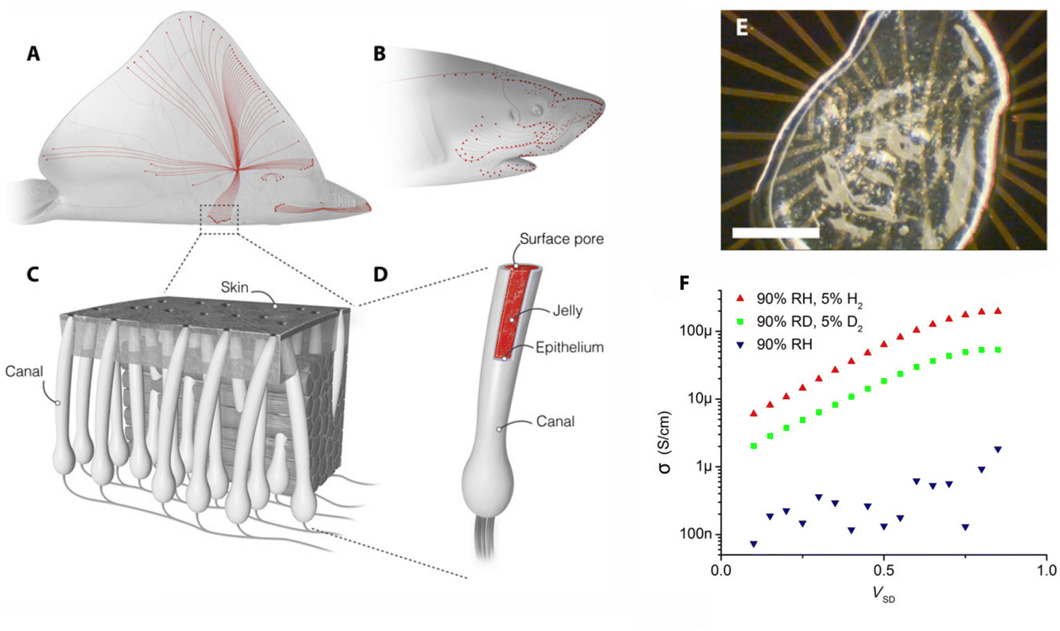 | ||
| Fig. 1 (A) and (B) Skates and sharks locate their prey by detecting the weak electric fields naturally generated by biomechanical activity. (C) A network of electrosensory organs called the Ampullae of Lorenzini is responsible for this sense. (D) An individual ampulla consists of a surface pore connected to a set of electrosensory cells by a long jelly-filled canal. Sharks and skates can sense fields as small as 5 nV cm−1 despite canals travelling through up to 25 cm of noisy biological tissue. (E) Sample of the Ampullae of Lorenzini jelly on an electrical device. Scale bar = 0.5 mm. (F) Four-point probe conductivity results from R. binoculata. Conductivity increases exponentially with voltage up to about 1 V, suggesting that conduction is limited by potential barriers. Deuterium conductivity (green symbols) at 90% D2O humidity (RD) is half as large as proton conductivity (red symbols) for all voltages. Ion conduction in the hydrated state (blue) is minimal. Reproduced from 7; copyright © 2016 The Authors, some rights reserved; exclusive licensee American Association for the Advancement of Science. This work is licensed under a Creative Commons Attribution 4.0 CC-BY-NC International License. | ||
The effectiveness of biological materials has motivated extensive research on their use for energy and electronic purposes.10–14 Social and environmental concerns have made the need for bioinspired and biodegradable materials increasingly urgent, since human development has not been without consequences. Whether these consequences are related to the environment (e.g., global warming, climate change and an ever-increasing population), energy consumption, waste management, or other issues, these problems have gradually become so complex that they can only be addressed on a global scale. Echoing this need, the United Nations (UN) has been issuing a call to action to end this systematic overlooking of the real cost of human progress by implementing game-changing technologies that can lead to sustained development.15,16 To this end, 17 goals have recently been identified that require prompt action from human agents in areas of vital importance, if human society and the planet are to evolve into a more sustainable, harmonized coexistence.16 More recently, in July 2020, the UN Secretary-General, in the midst of the COVID-19 outbreak, again exhorted world leaders to favour a “clean energy path” in post-pandemic economic recovery plans, urging the international community to move away from traditional energy sources, like coal and fossil fuels, for the sake of three vital reasons: health, science, and the economy.17
Biopolymers, such as proteins and polysaccharides, are expected to play a crucial role in prioritizing clean economic recovery packages that can bring the world closer to the goals defined by the Paris Agreement. Due to the extremely high number of polar groups in their backbone, they are major mediators in the charge transport mechanisms present in biological systems. From a social–economic point of view, these materials are now more cost-effective than ever, representing an increasingly viable alternative to the current consumption of petroleum-based materials and all the problems associated with their use, particularly their resistance to biodegradation and consequent environmental accumulation.13,18–21
As the most abundant biopolymers in nature, polysaccharides are easily available and relatively inexpensive. Suffice it to say that cellulose, chitin, and starch stand among the most abundant organic compounds in the world.22–24 Their biological roles in structural functions, communication, and as energy resources have driven the development of an almost infinite number of chemical structures, each tailored for a specific function.
Polysaccharides are obtained by the combination of multiple saccharide units (typically addressed as glycans) linked together by glycosidic bonds. These bonds, which can be formed in various ways, underlie the wide diversity of possible structures, spanning from linear to highly branched. Further heterogeneity can emerge by introducing different units with special characteristics, such as units comprising amino or sulfate groups (amino or sulfate sugars, respectively) or units lacking an oxygen atom at a given position (deoxy sugars). Adding to all this, the staggering number of hydroxyl groups present per chain, along with the seemingly random forms of branching, combine to form supramolecular structures that display properties that cannot be attributed to their parent monomers.24–27
Polysaccharides can thus be linear or branched. They can be formed from only a single glycan or from several different monomeric units. Their molecular weight can vary from low to high, with different degrees of polydispersity. They can be monofunctional (incorporating only hydroxyl groups) or polyfunctional (including hydroxyl, sulfate, carboxyl, and amino groups, among others); hydrophilic or hydrophobic; flexible or rigid. In their natural state, nearly all polysaccharides are biocompatible, biodegradable, and non-toxic.
Yet, polysaccharides do present some demerits, including poor mechanical and tensile strength, a swelling profile that is not easily controlled, and high thermal sensitivity. Their biodegradability, although it may avoid pollution-related problems, might also be a drawback, as it limits long-term stability. To overcome these setbacks, several different strategies have been proposed and adopted over the last few years.
Polysaccharides can be modified either chemically (e.g., via the introduction of ionic or hydrophobic groups) or physically (e.g., via thermal treatment).28–30 They can also be combined with a wide variety of species, ranging from metal cations and inorganic entities to organic acids and other biopolymers, to create a plethora of materials with different sizes, shapes, and forms, such as gels, membranes, nanoparticles (NPs), fibres, films, sponges, and mesoporous materials.31 Not surprisingly, from key-based chemicals to specialty materials, polysaccharides have progressively been established as ideal materials from both environmental and economic points of view.12,32,33
Research on the conductivity of polysaccharides has been a thriving field, attracting increasing attention with each passing year (Fig. 2). From the initial conductivity studies in solution media to the design of functional materials, these biopolymers have found applications in various solid-state electrochemical devices, such as batteries, supercapacitors, photovoltaics (e.g., electrochromic devices and solar cells), fuel cells, or sensors.13,34–38
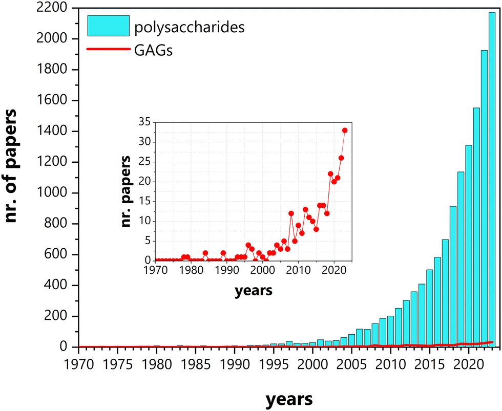 | ||
| Fig. 2 Number of papers published between January 1970 and December 2023, mentioning conductivity and polysaccharides (cyano bars) and glycosaminoglycans (GAGs) (red line and inset). Source: Scopus. | ||
Although the initial studies on the conductivity of polysaccharides addressed a diverse group of compounds, (i.e., cellulose, chitosan (CHT), starch, hyaluronan (HA), agarose, pullulan, and gum Arabic),39 efforts were soon focused on a limited number of polysaccharides, namely cellulose, chitin/CHT, and, to a lesser extent, starch and alginate.34–36,38,40 This trend has only recently been inverted with increasing reports on other, less explored, polysaccharides, such as glycosaminoglycans (GAGs), carrageenans, dextran sulfate, gums, pectin, and others (Fig. 2 and 3). In spite of this diversifying trend, the scientific literature on these lesser studied polysaccharides remains random and sparse, still lacking consolidation.
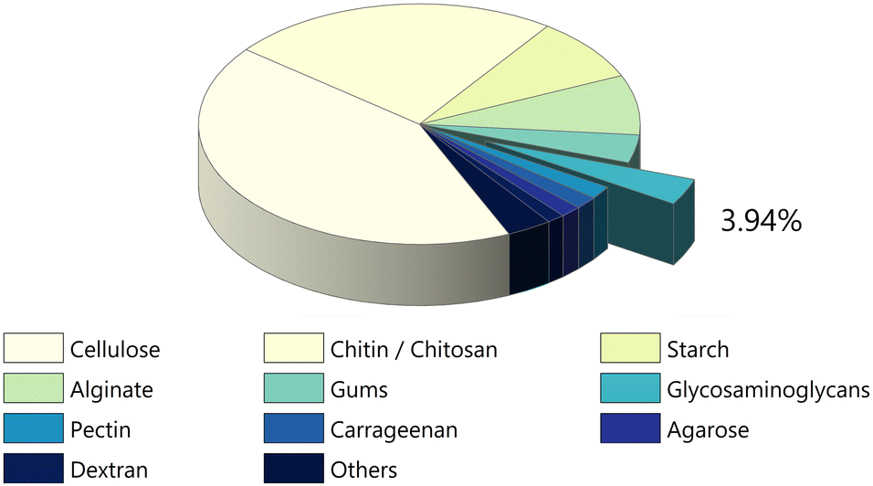 | ||
| Fig. 3 Number of papers devoted to conductivity per class of polysaccharide up until December 2023 (data retrieved from Scopus search engine). The earliest recorded paper is different for each class (1940 for cellulose; 1980 for chitin/chitosan; 1966 for starch; 1950 for alginate; 1930 for gums; 1978 for GAGs; 1957 for agarose and so on). Even so, research dealing with conductivity was so scarce before the 1990s that these differences are not statistically relevant. | ||
The family of GAGs is of particular interest to us. These polysaccharides, which have been receiving considerable attention in the biomedical field,41–46 have until recently been mostly disregarded for other possible applications. When we recently reported on the conductivity of a chondroitin sulfate/citric acid system, only a handful of papers dealing with this subject were cited.47 This lack of information prompted us to dig deeper and realise that over the last 45 years, work concerning GAGs and conductivity has been published regularly, even if modestly, establishing a sort of undercurrent in the midst of all the work being done within the greater family of polysaccharides (Fig. 2). In particular, interest has been building up in the last few decades, perhaps echoing the vision of GAGs as polyelectrolytes,48 which has been recently brought back to light,49 highlighting their potential interest as attractive candidates for electroactive devices. In fact, a search conducted this December 2023 on both the Web of Science and Scopus databases, cross-referencing keywords such as “glycosaminoglycans”, “hyaluronic acid”, “hyaluronan”, “heparin”, “heparan”, “chondroitin”, “dermatan” and “keratan” with either “proton conductivity”, “electric conductivity”, “ionic conductivity” or “electroconductive”, allowed the identification of more than 275 papers with the first studies on conductivity dating back all the way to 1978.
The absence of any compiling work on the subject is a clear sign of the need for comprehensive and solidified information on the current state of development of electroactive materials containing GAGs. Two recent reviews addressing the use of GAG-modified conductive materials for biomedical applications have started to change this situation.50,51 Even so, both of them are limited in their scope: one of them addresses only HA-based conductive materials;50 the other is built around the use of GAG-modified conductive polymers.51 What we are proposing here is to go one step further. To look at the whole body of research that has been done and is currently being developed, and ask, ‘Now what? What else is it possible to achieve with these materials?’
One of the aims of this paper is to provide a thorough account of the whole 45 years of work on GAGs, in an attempt to draw attention to the pivotal role these macromolecules can possibly play in the production of new sustainable electroactive systems. Another key goal of this paper is to give a critical overview of the latest advances in energy devices and flexible electronics comprising GAGs, thereby opening new avenues for the design of bioinspired eco-friendly energy-efficient materials and devices with enhanced performance.
2. Glycosaminoglycans
2.1. The family
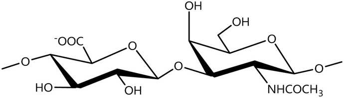
A GAG is a linear polysaccharide that possesses a characteristic repeating sequence of two monomers. One of these monomers is an amino sugar (D-glucosamine or D-galactosamine, in a N-acetylated form), whereas the other unit is usually, but not always, a uronic acid residue of either D-glucuronic acid or L-iduronic acid. Different combinations of a hexosamine with a hexuronic acid or hexose will therefore lead to different GAG structures. Both units are variably N- or O-sulfated and connected by different glycosidic bonds, which only adds to the heterogeneity of these macromolecules. GAGs are thus differentiated by their monomeric units, the number and location of sulfate groups, and the linkages between their monomeric units (Fig. 4).43,52,53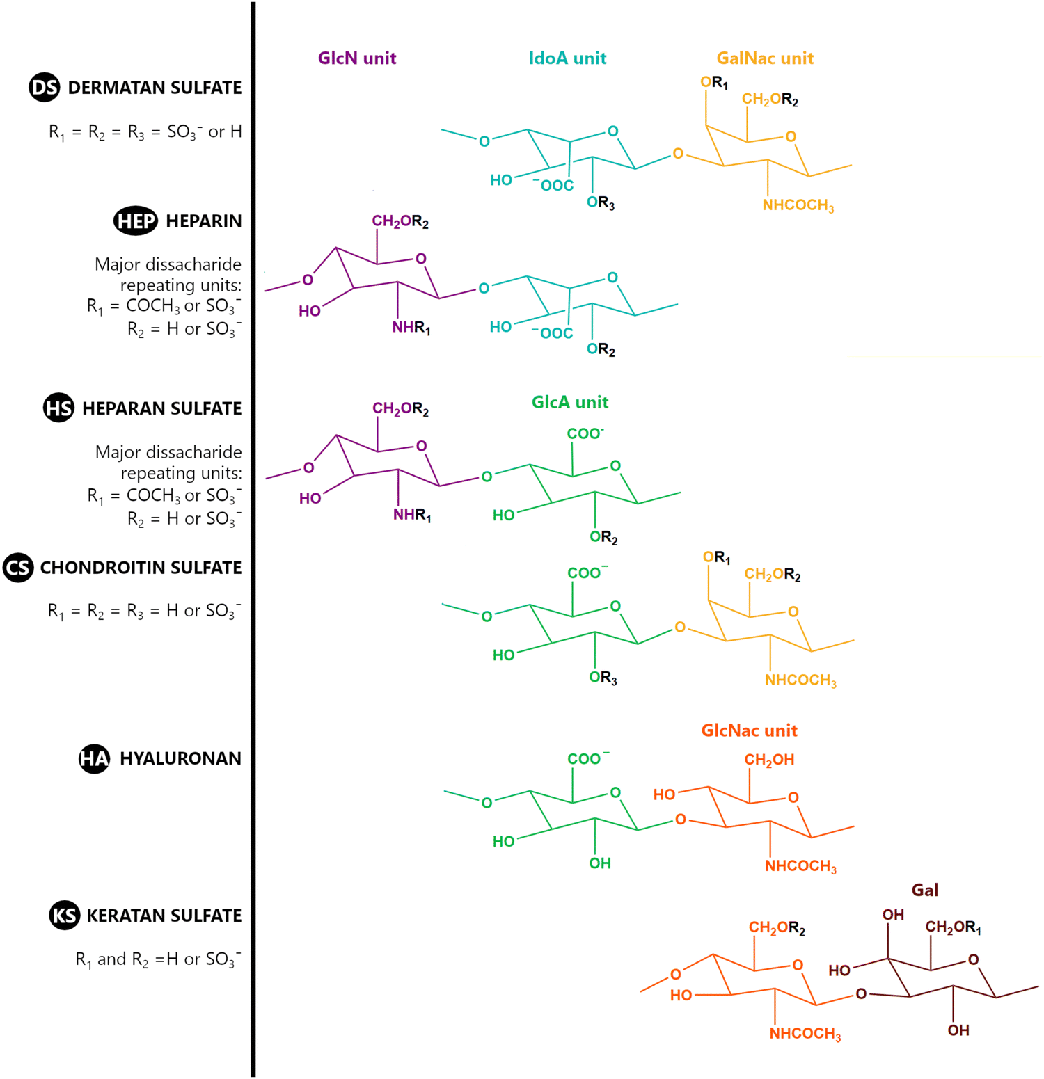 | ||
| Fig. 4 Structural representation of the main dissacharide unit in glycosaminoglycan (GAG) molecules, highlighting their common features. Units: GlcN is β-D-glucosamine; IdoA is α-L-iduronic acid; GalNac refers to N-acetyl α-D-galactosamine; GlcA refers to β-D-glucuronic acid; GlcNac is N-acetyl β-D-glucosamine; and Gal refers to D-galactose. | ||
This diversity in chemical structures is, of course, intrinsically related to the biological functions that GAGs are expected to perform. GAGs are biosynthesized to perform specific roles in the organism, meaning that key factors, such as the sulfation pattern or the molecular weight (and hence physical properties like viscosity, chain flexibility, conformation, cation interaction, or others), are highly dependent on the tissue type in which these molecules are found.53–55 Being ubiquitously found in higher organisms, GAGs are known to improve the mechanical stability of connective tissues and to regulate key processes in their local biological environment.53,55,56 This has led to their extensive exploration for biomedical applications, such as drug delivery, wound healing, tissue engineering, inflammation, and immunotherapy, among others.41,43–45,57–59
Important GAG structures include the non-sulfated hyaluronan (or hyaluronic acid, HA, as it is usually known), as well as the sulfated polysaccharides heparin (HEP) and heparan sulfate (HS), chondroitin sulfate (CS) and dermatan sulfate (DS), and keratan sulfate (KS) (Fig. 4).
HEP and HS are structurally related, as they share a common amino sugar (D-glucosamine), which is linked to either a L-iduronic acid (HEP) or D-glucuronic acid (HS) through a α(1–4) glycosidic bond. HEP and HS are sulfated at both their monomeric units (Fig. 4). However, their sulfation patterns are distinct, with HEP featuring a more even distribution of sulfate groups throughout its polysaccharide chain, while HS exhibits regions with high sulfate content contrasted with others with lower or even no sulfate content.43,52,60 The degree of sulfation is thus higher in HEP. Indeed, HEP is regarded as having the highest negative charge density of all known biomacromolecules.43,60
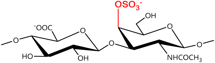
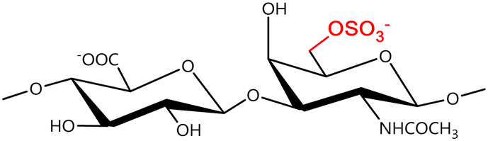
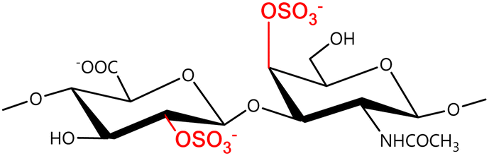
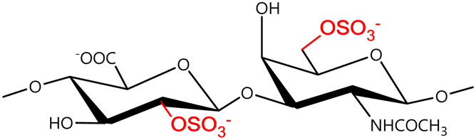
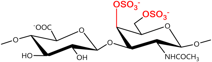
In a similar way, both CS and DS feature identical hexamine moieties (N-acetylated galactosamine), but different uronic acid monomers, which are linked by alternating β(1–3) and β(1–4) glycosidic bonds, respectively (Fig. 4). Thus, while CS is assembled from N-acetylated galactosamine and D-glucuronic acid, DS is obtained by combining the same amino sugar with L-iduronic acid.52,61 Both CS and DS are very diverse polysaccharides in terms of chain length, molecular mass, and charge densities.52,61–63 CSs can exhibit a wide variety of sulfation patterns, since any of the four hydroxyl groups present in the disaccharide unit can be replaced by sulfate groups.57 This has prompted a classification of CS according to the position of the said sulfate groups. Monosubstituted CSs usually have a sulfate group at either the C-4 or C-6 positions of the galactosamine residue and are known as CSA and CSC respectively. Di-substituted forms of CS include chondroitin-2,4-disulfate (CSB, R2 = H or R2 = SO3−, Table 1 and Fig. 4); chondroitin-2,6-disulfate (CSD, R2 = R3 = SO3− and R1 = H, Table 1 and Fig. 4) and chondroitin-4,6-disulfate (CSE, R1 = R2 = SO3− and R3 = H, Table 1 and Fig. 4). Other disaccharide sulfation patterns have been reported including higher degrees of sulfation and non-sulfated CS.48,57 The enzymatic conversion of the D-glucuronic acid residue in CS to various amounts of L-iduronic acid gives rise to DS, a stereoisomer of CS (Fig. 4).63 Like CS, DS can also undergo sulfation at C-4 and C-6 positions of the galactosamine moiety, as well as the C-2 position of the uronic acid, leading to a variety of different structures, either mono-, di-, or trisubstituted.52,62,63
| CS | Sulfation patterns | Form | DS |
|---|---|---|---|
 |
Non-sulfated | 0 | 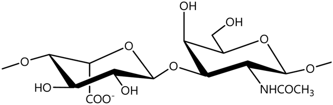 |
 |
Monosubstituted | A |  |
 |
C | 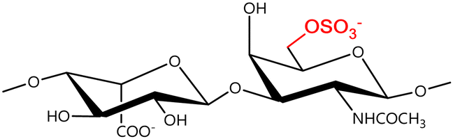 |
|
 |
Disubstituted | B | 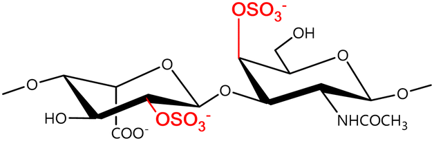 |
 |
D | 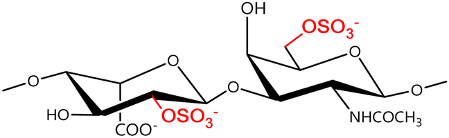 |
|
 |
E | 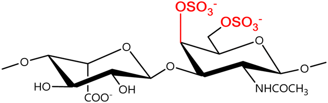 |
KS is formed through the combination of alternating units of N-acetyl-D-glucosamine and D-galactose through β(1–3) and β (1–4) glycosidic bonds (Fig. 4), making it the only GAG that lacks an uronic acid residue. It is a relatively small GAG, with chains ranging from 5 to 30 disaccharide units. It has a relatively low sulfation degree, as sulfate groups are present only on some of both monosaccharide units, always at the C-6 position (Fig. 4).52,64
HA is somewhat different from the other GAGs. It is the only member of the family that has maintained its simple primary structure devoid of any of the variations seen in other GAGs. HA is obtained through combinations of D-glucuronic acid and N-acetyl-D-glucosamine units connected by interchanging β(1–4) and β(1–3) glycosidic bonds (Fig. 4). Its uniqueness, as far as this group of polysaccharides is concerned, is also reflected in its size and sulfation pattern. It is the longest GAG of all, with molecular mass reaching up to 10 MDa and an extended length of 2–20 μm. It is also the only GAG which does not feature any sulfation pattern, and hence, it is the GAG with the lowest charge density.52,65,66
2.2. Stability, interactions, and reactivity
GAGs are found in living beings, usually operating in conjunction with proteins as part of supramolecular systems, which are destroyed when attempting to extract or isolate these compounds. As such, it should be noted that their structural features are not necessarily the same as those present when they operate in a biological system. After extraction and purification, GAGs are usually presented in the form of a salt, most commonly in the sodium form. This is also true for HA, in spite of being usually referred to by the traditional name “hyaluronic acid”. For all intents and purposes, and unless noted otherwise, the following applies to the anionic structures obtained after extraction and purification, regardless of the name they are designated.Like any other macromolecular system in an aqueous solution, GAGs achieve electrical neutrality in an aqueous medium through interactions with small counter-ions. The nature and extent of these interactions are defined not only by the size and shape of the macromolecular system, but also (and not less importantly), by the number and distribution of the charges in the said system.67,68 But the importance of counter-ions goes well beyond mere balancing of charges, since these species can affect both intramolecular and intermolecular conformational transitions.67
GAGs exhibit a highly hydrophilic nature as a result of the large number of hydroxyl, carboxyl, amide groups, and, in most cases, sulfate groups. The presence of both carboxyl and, especially, sulfate groups, effectively unprotonated at pH > 4.0 (pKa carboxylate ∼3–4; pKa sulfate ∼1.5–2; Fig. 5a), imparts a polyanionic character.52,69,70 These groups are suitable for interaction with a vast array of positively charged entities, ranging from metal cations to large positively charged macromolecules, such as CHT or proteins. The presence of sulfate groups and, to a lesser extent, carboxyl groups also promote the formation of H-bonds.
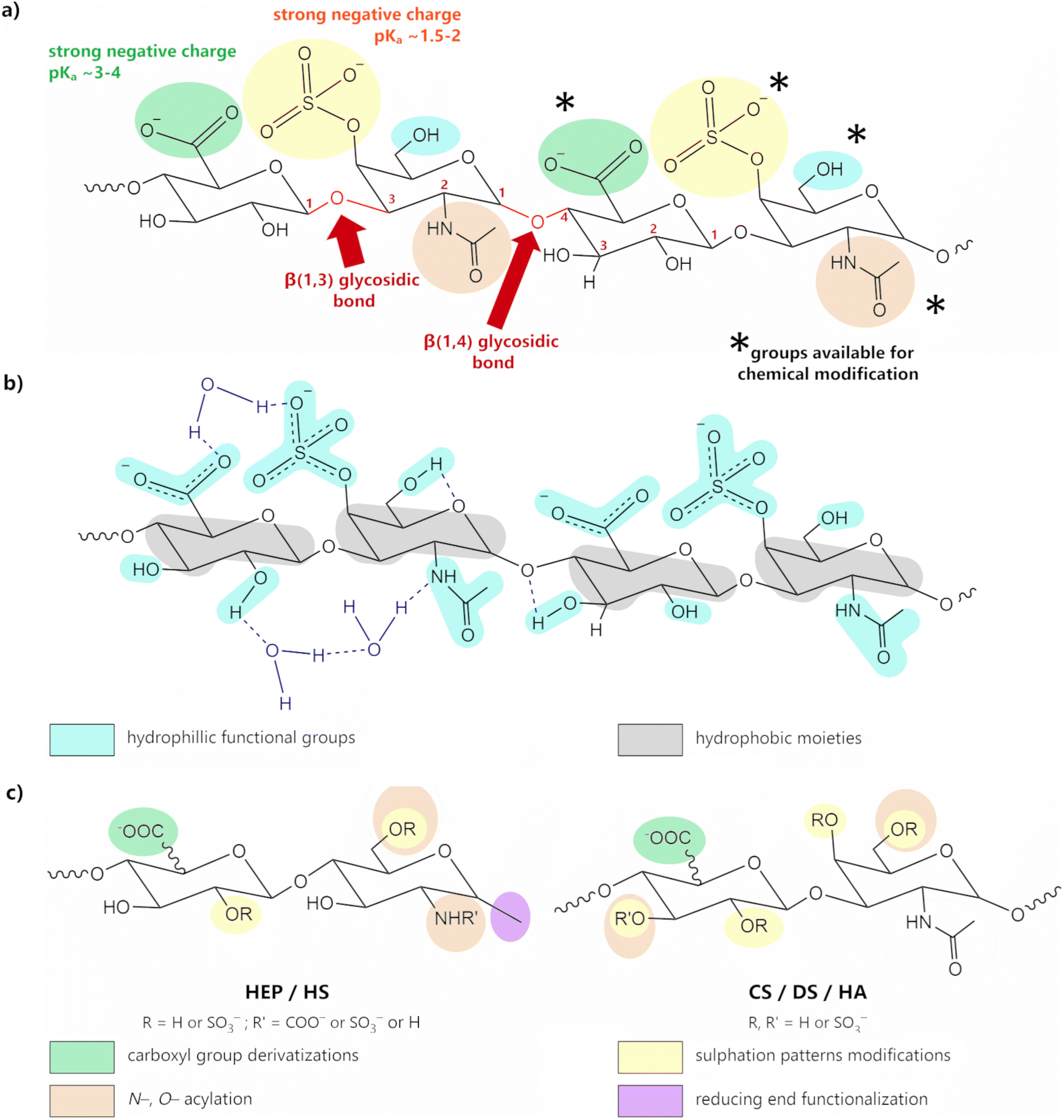 | ||
| Fig. 5 (a) Structural representation of CSA, highlighting its hydroxyl (blue), carboxyl (green), sulfonic (yellow) and amide (brown) groups, which are important for chemical modification. Adapted with permission from ref. 58; copyright © 2019 The American Chemical Society; (b) chemical structure of the CSA tetrasaccharide unit displaying both the hydrophilic functional groups (blue) and hydrophobic moieties (grey); H-bonds are represented by dark blue dashed lines; adapted from ref. 71 with permission from John Wiley and Sons; copyright © 2016 Wiley-VCH Verlag GmbH & Co. KGaA, Weinheim. (c) schematic representation of the possibilities for structural modification of GAGs; adapted from ref. 72; copyright © 2018 The Authors. Licensee MDPI, Basel, Switzerland. This work is licensed under a Creative Commons Attribution 4.0 CC-BY International License. | ||
Intramolecular H-bonding (either within or between GAG residues) leads to the formation of an amphiphilic special architecture in the shape of a helix-like structure, with a hydrophobic domain consisting of C–H bonds (Fig. 5b, in yellow), and a hydrophilic domain comprising polar groups (Fig. 5b, in blue).73–76 Unlike proteins or nucleic acid polymers, GAGs do not have a defined secondary structure—or, for that matter, any higher order structure—but rather experience a wide range of low-energy conformations, not only due to some degree of rotational freedom of the glycosidic bond, but also due to the extensive interactions occurring between GAGs and water molecules. Indeed, these structures are greatly enhanced in the presence of polar solvents, such as water, as the H-bond system is extended to include intermolecular bonding with the solvent molecules.65,75–78
GAGs are strongly dependent on their environment. Variables, such as pH, temperature, type of solvent, ionic strength, or any other factor that can disrupt the delicate balance between the attractive and repelling forces established around the polymeric chain, will affect them. Their viscoelastic properties, for example, are a direct result of the interplay between their conformational flexibility and the dense clustering of water molecules around the polar groups, which leads to the formation of three-dimensional (3D) gels.75,76
In this aspect, HA is quite interesting, since it has the ability to form meshworks in solution, even at low concentrations.79,80 Even so, these meshworks remain mobile across a wide range of pH conditions, including physiological conditions. This is due to the dynamic nature of their H-bonds, which change in response to increasing deformation frequency to a more elastic state; however, they are also easily restored to their initial structure once the applied stimulus is over. Thus, even though HA solutions are shear-thinning and exhibit a viscoelastic behaviour, they are not thixotropic.66,81,82 At low pH values, or more specifically in a narrow pH zone between 2.4 and 2.6, HA undergoes a sol–gel transition to form what is known as “putties” (elastic gels).83,84 This behaviour, which is easily more observable for high molecular weight HA—since low-molecular-weight HA might not have the necessary size to form the macromolecular network80,85—has been correlated with the establishment of very strong interchain H-bonds between the amide and the partially protonated carboxylic groups of adjoining chains, leading to the formation of HA fibers and the concomitant expulsion of water molecules from the polysaccharide surface.85,86 In much the same way, non-sulfated CS can also form macromolecular aggregates in solution, both with itself and with HA.80 The introduction of sulfate groups in the polysaccharide chain, however, leads to an increased charge density, which has an inhibitory effect on the ability of these sulfated polysaccharides to form aggregates. This will lead to solutions with distinct rheological properties, depending on the number and position of the sulfates in the polysaccharide chains.80,87
Variations in pH, promoted upon the addition of either acids or bases, will first lead to a rearrangement of the H-bonded network (which is accompanied by the appropriate changes of their viscoelastic properties),88 and secondly, if a sufficiently high (or low) pH is reached, it will lead to the degradation of the whole structure through hydrolysis. This is particularly important in alkaline environments, as the conditions are favourable for the destruction of the H-bonded network and the consequent loss of stability of these compounds.89–91 Other factors contributing to the breakdown of the polysaccharide chain include temperature,90–92 the introduction of oxidative species,93–95 and enzymatic degradation.93,96
In the solid state, the same extensive H-bonded network is again one of the main factors influencing the properties of GAGs.97 Depending on their hydration level, GAGs can adopt a wide variety of structures, from stiffer and more compact structures, obtained at low hydration levels, to more elastic ones obtained at higher hydration levels.98 Indeed, several X-ray diffraction studies invariably pointed out the existence of a structural versatility in the way GAG molecules orient themselves, in a process intimately related to the different conditions in which these polysaccharides crystallise. It was also noted that counter-cations play a more important role than what was initially suspected in terms of the orientation of the polymeric chains and packing of the crystals by interfering with the GAG's H-bond system.52,65,99
When it comes to GAG films, the general understanding is that they are stiff and brittle. And while the films from sulfated polysaccharides like CS or HEP often do need additional components (plasticizers and cross-linkers) to improve their mechanical properties, HA is quite filmogenic.100–103 In both cases, these properties can be correlated with each polysaccharide's own charge density and the ability to form dynamic aggregates in solution. Hence, the dynamic clustering observed for HA chains allows for a better settlement in the film formation process. On the other hand, the higher charge density encountered in CS or HEP can lead to increased electrostatic repulsion between these polysaccharides, as well as an increased clustering of solvated cationic charges, both of which can negatively impact film formation.
Overall, thermal stability studies consistently indicate that the degradation temperature for GAGs ranges between 200 and 300 °C, under both an inert and an oxidative atmosphere.47,104–107 Degradation starts with the cleavage of glycosidic bonds, together with the more labile polar groups. This process is followed by the breakdown of the C–C bonds in the carbon backbone between 300–350 °C, resulting in the formation of an organic residue. Under an oxidative atmosphere, an additional step is observed from 500 °C upwards, associated with the oxidation of the organic residue and the concomitant formation of inorganic subproducts due to the presence of metallic counter-cations.47,105–107 As expected, the onset temperatures are a function of the specific material being used. Variations in the onset temperature were reported for GAGs obtained from different sources,108 in different forms,107 or even with different counter-cations.109 There is, however, an additional thermal event prior to the degradation process, between 50 and 150 °C, which involves the gradual loss of water molecules loosely bound or otherwise trapped within the GAG framework. Depending on the water content, this loss can lead to changes in the mechanical properties of the materials, leading, for instance, to the gel–sol transition.47,87,110
GAGs’ properties can be modulated in order to suit specific applications. This might mean improving the mechanical properties, enhancing thermal stability, or simply regulating the hydrophilic character of these molecules. The existence of a high number of sulfate, carboxyl, or amide groups provides numerous different strategies for functionalization, including the adjustment of the sulfation patterns, the modification of functional groups, or even ring opening (see Fig. 5c).55,71,111–113
3. Conductivity
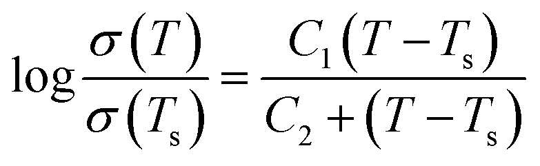
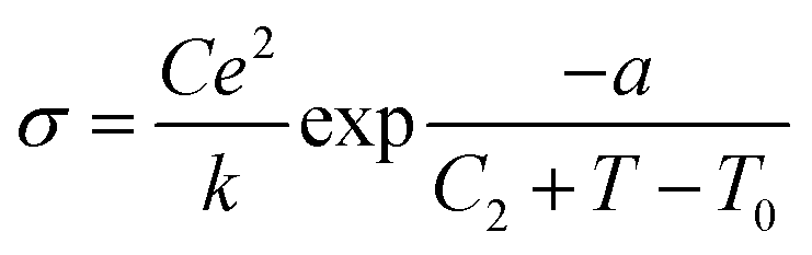
There are two classes of ionic conductive compounds:114 (1) ionic conductors (ICs), with a conductivity of up to 10−5 S cm−1 and activation energies ranging from 0.6 to 1.2 eV; and (2) superionic conductors (SICs), with conductivities higher than 10−4 S cm−1 and activation energies typically lower than 0.4 eV. The difference between ICs and SICs lies basically in the way the diffusion of the charge carriers occurs. In ICs, ion conduction depends on the formation of defects via a thermally activated process. In contrast, in SICs, the charge carriers are already present, and their diffusion is favoured by the low packing degree of the material's structure, which promotes dynamic disorder and diffusion of the charge carriers.For many ionic conductors, the following Arrhenius conductivity law, derived from the Nernst–Einstein law, is valid:
σT = [(D0C0e2)/k][exp − (Ef + Ed)/kT] = σ0![[thin space (1/6-em)]](https://www.rsc.org/images/entities/char_2009.gif) exp − Ea/kT exp − Ea/kT |
In the case of glasses and polymer electrolytes, which are considered neither truly solid electrolytes nor truly liquid ones, other conductivity laws are used.115 For both types of electrolytes, a Vogel–Tamman–Fulcher (VTF) type conductivity relation is often assumed:
|
σ = σ0exp(−B/k(T − T0))
| (1) |
Another conductivity law widely used in this context is the more complex one proposed by Williams–Landel–Ferry (WLF):
 | (2) |
 | (3) |
An IC is named a protonic conductor (PC) if protons can be transported throughout it and converted into hydrogen gas at the cathode. This process should proceed as long as protons are supplied at the anode. Typically the conductive species may be “isolated” protons, but also, oxonium ions (the simplest one being the hydronium ion, H3O+), ammonium ions (NH4+), hydrazinium ions ([H2N–NH3]+), and hydroxyl (OH−) groups.116
PCs can be divided into three categories on the following basis: (1) the defect mechanism in a densely packed structure (Fig. 6a). Anhydrous PCs, for which the activation energy is high and the proton conductivity is associated with intrinsic and extrinsic defects, belong to this class. In this case, the conductive species are protons or proton vacancies; (2) a loosely packed lattice with a high concentration of mobile species (Fig. 6b). Such PCs have high σ0 and high Ea at low temperature. The conductive species are usually H3O+ or NH4+ ions. As a rule, the increase in temperature induces dynamic disorder in the mobile species, leading to a major drop in Ea; (3) A quasi-liquid state with proton jump contribution (Fig. 6c). This type of state can be found within a structure (e.g., bulk conductors) or at the surface (e.g., in gels). Various mobile species can move at different rates using different paths, and some species (e.g., the proton) may even jump from site to site. The latter process is usually called the proton jump or Grotthuss mechanism, as explained in detail below.
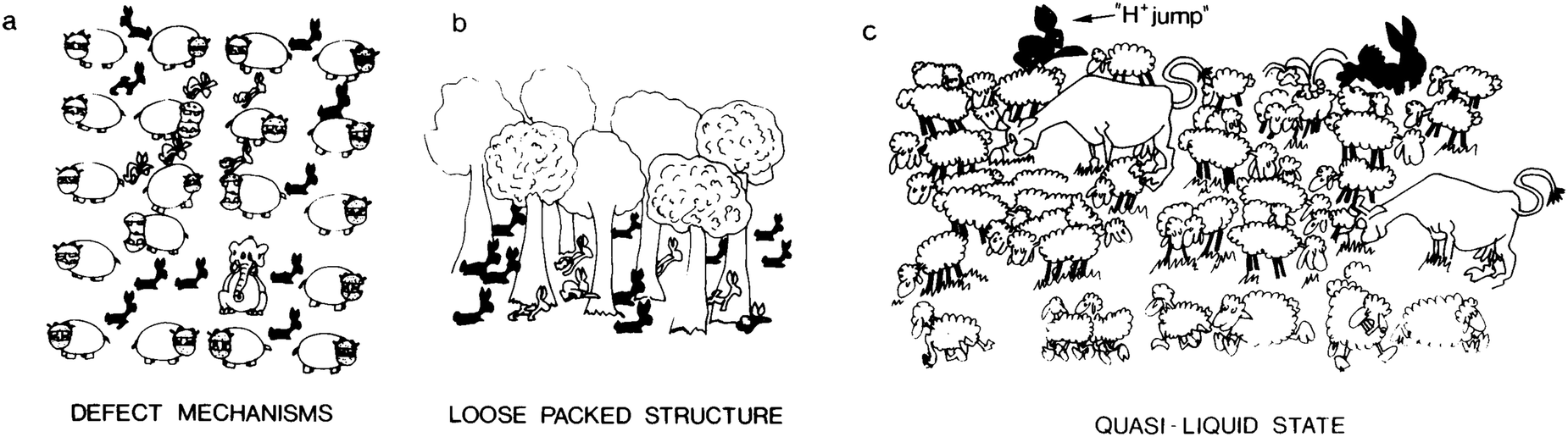 | ||
| Fig. 6 Schematic illustration representing the main proton transfer mechanisms: (a) defect mechanism in a densely packed structure; (b) loosely packed structure with a high concentration of mobile species; and (c) quasi-liquid state with a proton jump contribution. In (a), the conductivity is facilitated by intrinsic (interstitial rabbits) or extrinsic (impurity: elephant) point defects. An orientation defect (hippopotamus in the wrong orientation) can also favour the disorder of rabbits; (b) the tree sublattice is a perfectly stable, loosely packed structure, and a high rabbit disorder can exist without affecting the host lattice; (c) only the mobile species sublattice is considered here; these entities are moving at different speeds in different directions, and some are hopping: this may be the image of a quasi-liquid or surface liquid. Reproduced from ref. 116, with permission from Cambridge University Press, copyright 1992. | ||
3.1. Proton conduction mechanisms
In 1996, Kreuer et al. provided a comprehensive analysis of the proton conduction mechanisms in materials.117 Their starting point was the recognition that the proton is a very active entity, strongly interacting with its environment due to the lack of an electron shell. Materials that exhibit high proton conductivity share in common the fact that they comprise H-bonds. These intermolecular interactions, which are considerably weaker than other chemical bonds, have two key features: they easily adapt to the surrounding environment and demonstrate high thermal sensitivity. Molecular liquids with prominent hydrogen bonding (e.g., H2O and NH3) show transient short-range ordering with significant time- and space-oscillations. However, when stronger bonds (e.g., ionic or covalent) are present, the oscillations of H-bonds become restricted. In this context, and for the sake of clarity, it is useful to distinguish the proton environment in a metal and a non-metal. The chemical environment which surrounds the proton in a metal is the delocalized electron density of the metal conduction band. In such a case, the proton will act essentially as a hydrogen atom with a fraction of protonic or hydridic character, depending on whether the energy of the H1s state is higher or lower than the metal's Fermi energy (EF), respectively. As a consequence, in metals, high coordination numbers of four or six, along tetrahedral or octahedral geometries, respectively, may be expected for the proton or hydrogen. However, the scenario changes rather drastically, when a non-metal is involved. The proton will now interact strongly with the valence electron density of its nearest or two nearest neighbours. From here, three situations are likely to occur: (1) if the proton's neighbour is an isolated oxygen, far from other electronegative species, then an O–H bond with a length shorter than 100 pm will be formed; (2) if the average separation between two proton neighbours (e.g., two oxygen atoms) is ≈250–280 pm, then the proton will be able to form two bonds. One of the neighbours will act as a proton donor, while the second will serve as a proton acceptor. The proton donor will form a strong (short) bond, whereas a weak (long) bond will be formed with the proton acceptor. This represents the typical asymmetrical and directional H-bond found in many systems, usually represented by the notation O–H⋯O. (3) Occasionally, if the distance between the two oxygen atoms is very short (≈240 pm), then a symmetrical H-bond may be formed, which will be composed of two equivalent hydrogen bonds (O⋯H⋯O).In 1969, Fischer et al.118 concluded that the dynamics of the proton environment assist proton conductivity. Thus, if the host system where the proton is confined is a rigid array with a rather low concentration of electronic charge carriers, local motion of the protons may be expected, but no translational motion (i.e., diffusion, which is in turn intimately associated with proton conductivity).
Two well-established limiting mechanisms are usually employed to describe proton diffusion: the vehicle mechanism119 and the Grotthuss mechanism120 (Fig. 7).
 | ||
| Fig. 7 Schematic representations of proton conductivity in the presence of water. Left: Vehicle mechanism: protons conduct via molecular diffusion of protonated water clusters; Centre: Grotthuss structural diffusion mechanism – water fluctuations favour proton conduction; Right: Grothuss packed-acid mechanism – acid–acid interaction favours proton conduction, but water does not move. The stick men with balls illustration above was adapted from ref. 119, with permission from John Wiley and Sons. Copyright © 1982 by Verlag Chemie, GmbH, Germany. | ||
The vehicle mechanism relies on proton migration, assisted by the translational dynamics of larger species. This means that the protons do not migrate as single H+ entities but rather diffuse together with a so-called vehicle (e.g., H3O+ or NH4+) (Fig. 7, left). Alongside it, the counter diffusion of unladen vehicles (e.g., H2O or NH3) guarantees the net proton diffusion. The vehicle, characterised by a diffusion coefficient, ΓD, that corresponds to proton conduction, basically serves as a proton acceptor (Brønsted base) with respect to its crystallographic environment.
In contrast, according to the Grotthuss mechanism, the vehicles do not move from their position in the material, but instead exhibit marked local dynamics. As a consequence, the protons are transferred vehicle-to-vehicle within an array of hydrogen bonds (Fig. 7, right). This process comprises the reorganisation of the whole structural pattern of the proton environment, including the reorientation of individual species (or groups of species), yielding a continuous pathway for proton migration. This reorganisation is, most of the time, ensured by the reorientation of the solvent dipoles (e.g., H2O).
The Grotthuss mechanism is associated with two relevant rates: the proton transfer coefficient (Γtrans) and the proton environment reorganization coefficient (Γreo). Both coefficients are intimately associated with ΓD. At high temperatures, the progressive stretching/rupture of H-bonds annihilates proton transfer, releasing translational degrees of freedom. As a result, the Grotthuss mechanism gradually transitions to a vehicle-type mechanism which does not require an infinite H-bonded network.
According to recent reports,121 the Grotthuss mechanism can be further subdivided into two variations: (1) the structural diffusion mechanism, which requires water movement (Fig. 7, centre), similar to the situation occurring in the vehicle mechanism (Fig. 7, left) and (2) the packed-acid mechanism, which does not entail the movement of water (Fig. 7, right), is characteristic of highly concentrated (packed) acids. The latter mechanism has raised much interest, because of its important technological implications. For instance, it might contribute to proton conductivity in materials operating at or below the water freezing temperature (−40 °C). Moreover, it could be a way of improving proton conductivity under low-humidity conditions.
3.2. Proton conduction of glycosaminoglycans
Let us now focus on H2O-supported proton conduction, which is a ubiquitous chemical process. Suffice to say, it lies at the root of all acid/base chemistry.122 It is present in biological systems, in the synthesis of biomolecules, and in power-generating processes.123–125 It is also of prime importance in the context of energy materials, because the proton conductivity of the polyelectrolytes usually employed in fuel cells is enhanced with the increase in relative humidity (RH).117,126As mentioned above, a proton does not exist as an independent entity in an aqueous environment. It immediately associates with either a single H2O molecule or a small cluster of H2O molecules, to give rise to the H(2n+1)On+ cations, the simplest of which is H3O+. These cations can move through the medium as an independent unit, as described by the vehicle mechanism (Fig. 7, left).119 Yet, it is worth emphasising that the vehicle process does not, by itself, account for the abnormally fast mobility observed for the proton when compared to other ions with similar sizes. That is exactly the situation of the potassium ion (K+) which has a diameter of ∼3.0 Å, thus being close to that of H3O+ (3.3 Å).117,127,128 The reason for such a disparity in mobility lies in the ability of H2O to form a highly dynamic H-bonded system. In such a system, as pictured by the Grotthuss mechanism, the proton moves along a string of H-bonded H2O molecules in a two-step process comprising: (1) fast interconversion of an H-bond into a covalent bond from an adjacent H2O molecule; and (2) rotation and reorientation of the H2O structure to accept the extra charge. This reorientation regenerates the H2O molecule string, guaranteeing further proton translocation. Proton hopping is a low-energy barrier (∼1 kcal mol−1) process (Fig. 7, right).117,128,129
The discovery of strings of H2O molecules inside the cavities of various proteins soon led to the idea of proton hopping to encompass other entities, such as functional polar groups capable of sustaining a H-bonded system.127,129 This concept has since been refined with the introduction of the notion of proton wires by Nagel and Morowitz,130,131 which they considered to be the fundamental structural element of proton transport through biomembranes. Proton wires may be defined as low impedance continuous H-bonded chains formed from the side groups of biomacromolecules (e.g., proteins and polysaccharides).3,127,129,130,132,133 Proton conduction in these systems is aided by biomacromolecule conformational changes.
As discussed in Section 2.2, GAGs possess a vast number of polar groups (carboxyl, amide, and hydroxyl), enabling them to establish an impressive H-bonded system, encompassing both the internal interactions between these groups as well as surrounding solvent molecules and other entities. Under these conditions, a proton can be transported along a path consisting of H2O molecules exclusively connected to each other through H-bonds or a path involving H2O molecules and polar functional groups from the GAG molecule (Fig. 8).
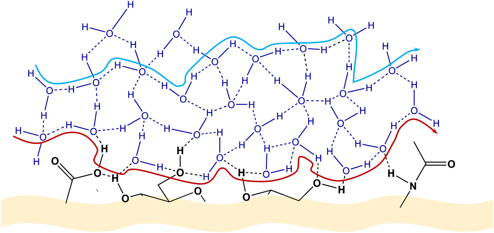 | ||
| Fig. 8 Suggested pathways of proton diffusion via a Grotthuss-like mechanism. Red pathway: proton diffusion involving water molecules and functional groups attached to the polysaccharide chain. Blue pathway: proton diffusion solely via water molecules situated within the HA biomolecule. Adapted from ref. 125; copyright © 2021 The Authors; published by The Royal Society of Chemistry. This work is licensed under a Creative Commons Attribution 3.0 CC-BY Unported License. | ||
Given the anionic state of GAGs, counter-cations are also expected to be present, both in solution and in the solid state. GAGs are usually commercially available in the form of sodium salts and used as such, meaning that sodium (Na+) ions are prone to being present in solution and can also contribute to the overall conductivity measured, unless procedures are applied to ensure the exchange of all cation content for H+ cations. Such a procedure is likely to enhance the proton conductivity of these molecules (due to an increase in the overall amount of H+ and the creation of acidic proton wires), but at the same time, the higher acidity might lead to undesired reactions, such as the acidic hydrolysis mentioned in Section 2.2. On the other hand, the existence of counter-cations capable of positioning themselves between two H2O molecules, due to their electrostatic interaction with the polar groups present in the GAG molecules, will invariably lead to changes in the H-bonded network and thus to modifications in the ability of a proton to be transported by means of a Grotthuss-like mechanism.119,134
Therefore, the conductivity properties of GAGs should be understood, not only in the context of the ability of GAGs to facilitate proton transport, but also in terms of the contribution of other factors, such as solvation or level of hydration, salt content, and others capable of influencing measurements.
3.3. Conductivity measurements
To accurately assess the conductivity of GAGs, a variety of specialized experimental techniques are available. These methods are designed to discern between ionic and electronic contributions, ensuring precise measurements. Among these, electrochemical impedance spectroscopy (EIS)135 stands as a powerful technique offering valuable insights into the electrical properties of conductive GAG-based materials and their interface with electronically conducting electrodes. EIS offers several advantages, including its non-destructive nature, high sensitivity, and capability to probe a wide frequency range. Moreover, its versatility enables investigations under various experimental conditions, such as different electrolyte compositions, temperatures, and electrode materials. In the context of GAGs, EIS can be particularly useful for understanding hydration shells, ion mobility, and cross-linking effects within the polymer matrix, which affect their ionic conductivity.115,117,136 It can thus help elucidate the electrochemical interfaces between the GAG-based systems and their surrounding ionic environment.68,137–139The theoretical basics of EIS are found profusely in the literature.136,140–142 A simple overview of EIS will be given as follows for readers less acquainted with this subject and willing to measure the ionic conductivity of GAG membranes.
In a typical EIS experiment, a sinusoidal low-amplitude voltage (E(t) (where t is time) is applied to the system. As a consequence, a linear current density j(t) with the same frequency as the input, but different phase and amplitude, results. The ratio between E(t) and j(t)) is called impedance (Z):
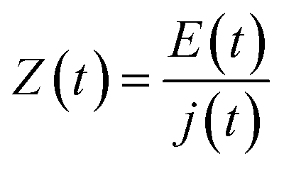 | (4) |
The resulting response (current in this case; voltage if a current is applied instead) is then measured across a broad spectrum of frequencies. This enables the evaluation of processes occurring at different timescales. For instance, in the high-frequency range, only fast phenomena (e.g., ion migration) will be monitored, whereas at low-frequency, slow processes (e.g., diffusion) will be scrutinized.
The alternating input E(t) and the output current density j(t) may be expressed as
| E(t) = |ΔE|sin(ωt) | (5) |
| j(t) = |Δf|sin(ωt + t) | (6) |
To represent the complex data, two graphs are usually employed: (1) the Nyquist plot, and (2) the Bode plot. By far, the most widely used is the Nyquist plot, which is suitable for analysing resistive processes. The Bode plot, on the other hand, is useful for studying capacitive systems. Both plots provide two valuable pieces of information: |Z|
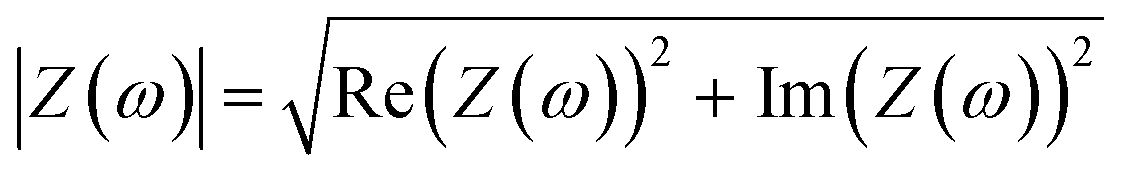 | (7) |
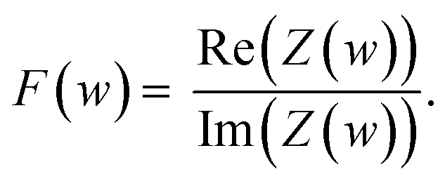 | (8) |
For the interpretation of these plots, it is often helpful to model the electrochemical system under study as an equivalent electrical circuit containing electrical components (typically, resistors and capacitors). Let us consider the very simple equivalent circuit shown in Fig. 9a. This is the archetypal equivalent circuit adopted to determine the conductivity of solid-state electrolytes, such as polymer-based electrolytes. The measurement assumes that the conduction in the electrolyte is purely ionic and implies using an electrochemical cell with ion-blocking electrodes, such as platinum, stainless steel, or gold. This type of electrode blocks ion transport but enables electronic transport. The circuit showcased in Fig. 9a is composed of a resistor R0 combined in series with an (RbCb) element and a capacitor Ce. R0 represents resistances from wires and contacts, Rb (in Ω) is the bulk resistance of the electrolyte, Cb (in Farad (F)) is the capacitance of the electrolyte due to polarization phenomena, and Ce is the capacitance of the electrode, also associated with polarization processes. For such a circuit, ideal Nyquist and Bode plots such as those schematically reproduced in Fig. 9b and c are obtained, respectively. The high-frequency range of the Nyquist plot contains a single semicircle with an offset of R0, providing relevant information on the electrolyte properties (Rb and Cb). From the frequency at the top of this semicircle, the time constant τ (with τ = (RbCb), where ω in radians s−1 and ω = 2πf) associated with the conduction process may be inferred. The low-frequency range, related to Ce and manifested as a vertical spike, provides information on the electrolyte/electrode interface. In practice, the semicircle is seldom perfect and the spike is in general not vertical. The latter effect may be caused by poor electrolyte/electrode contact or by the fact that the electrodes are not perfectly ion-blocking.
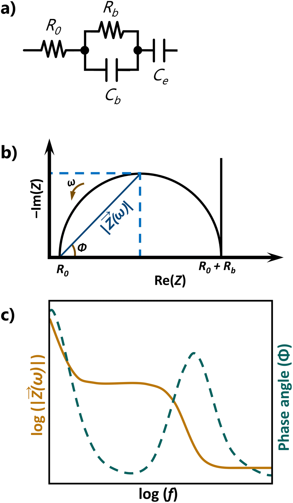 | ||
| Fig. 9 (a) Equivalent circuit, (b) Nyquist plot, and (c) Bode plot for an ideal ion conducting electrolyte. | ||
The plateau followed by a slope of −1 in the Bode plot (orange line in Fig. 9c) corresponds to the semicircle in the Nyquist plot.
The Rb value derived from the intercept of the Nyquist complex impedance plot with the real axis, and the calculation of the electrolyte area (A, in cm2) and thickness (l, in cm), enable the determination of the ionic conductivity (σ) of the electrolyte, using the following equation:
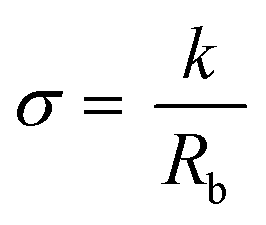 | (9) |
| k = l/A | (10) |
4. Methodology and points of concern
A comparative analysis of the conductive properties of different GAG-containing materials is not as straightforward as one might think. Two major points of concern have constantly been raised during the writing of this manuscript.The first concern, which is to be expected given the subject of this paper, pertains to the great variety of structures that can be found for practically all the polysaccharides under examination. As mentioned above, each GAG molecule is unique to the living tissue it was sourced from. This implies that differences in sulfation patterns, molecular weight, changes in the disaccharide units, or others, should impact their conductivity properties, since these changes all influence the number and type of polar groups anchored on the GAG backbone and, ergo, the extent of its H-bonded system. Hence, it is necessary to establish as clearly as possible the nature and source of what is being used in the various experiments, something which was found lacking in a significant number of papers, where the authors limited themselves to generically name the material they used and its distributor. And yet, just CS alone has about half a dozen better-known structures that feature either mono- or di-substituted sulfation patterns, of which CSA and CSC are the most often used in research.
The second concern involves the conductivity measurements themselves. In particular, it deals with both the extremely limited information about the conditions in which these measurements were made (the all-too-common absence of data on relative humidity (RH) and temperature) and the variety of methods used in obtaining the conductivity data. In this aspect, RH is critical for a correct evaluation of the conductivity since GAGs are known for their hygroscopic character.97 In a 1995 clarifying report, on the influence of RH on the conductive and mechanical properties of HA films, RH levels of 44, 76 and 98% led to conductance values of 1.8 × 10⁻⁵, 2.05 × 10⁻⁴, and 3.11 × 10⁻¹ mS−1, respectively, representing an increase of four orders of magnitude. The corresponding Young modulus values were 3500, 1150, and <0.1 MPa, respectively.97
But even if the authors provide the above information, the measurements reported may have been obtained with devices of different configurations, such as 2-point geometry devices and 4-point geometry devices. For example, the 2-point geometry device does not account for the contact resistance and will hence lead to a lower conductivity value than the 4-point geometry device.70 This very same situation is illustrated further down in Section 6, related to the conductive properties of GAG films. Moreover, since the resistivity measurements can also depend on the thickness of the prepared films, this parameter should also be considered in a mindful evaluation.
Another issue one may face when analysing reports on this topic over a wide timeframe is the plethora of ways that have been used by authors to address the conductivity of an electrolyte, as some have progressively fallen into disuse. An additional question is that the units indicated are sometimes misused. References to conductance, specific conductivity, or equivalent conductivity are often found in the literature. For the sake of clarity, it is of interest to mention some relevant aspects in this respect. Electrolyte conductance (G), defined as the reciprocal of the electrical resistance (R), serves as a measure of the material's intrinsic ability to conduct electricity. It is expressed in Ω−1, the official SI unit being Siemens (S). In contrast, the specific conductance (or simply conductivity (σ)) of an electrolyte, which is defined in S m−1, considers the distance the electrical current has to travel. Thus, conductance and conductivity are related according to eqn (11)
| σ = G × k | (11) |
The equivalent conductivity of an electrolyte is numerically equal to the conductivity multiplied with the volume in cm3 containing 1 gram-equivalent. The unit of equivalent conductance is S cm2 eq−1.
When preparing the present review, efforts were made by the authors to identify the GAGs as thoroughly as possible. This implied examining the structural characterisation and seeking information that might unambiguously identify the GAG being used or, at least, provide firmer identification to the readers. This was especially true with papers dealing with CS. Whenever a definitive identification was made, it was used in the presentation below, in detriment of that originally indicated by the authors. Otherwise, the authors’ designation has been maintained. This is why in the compilation below, some materials will appear as CS, with no indication of which form of CS it is, while others will appear with the appropriate identification.
Given what we found on the conductivity measuring conditions, data on RH, temperature, and device configuration have, for the most part, not been collected. The reader is advised to refer to the original papers for additional information on those parameters. The reports on the various conductivity values have all been standardised to the conductivity units mS cm−1. This was done in order to provide an easier comparison with different studies, as well as reference materials, such as Nafion-117, which is reported to have a conductivity of 78 mS cm−1 at ambient temperature and in a saturated atmosphere.9,143 Also, due to the nature of some of the reported composite materials, such as combinations of GAGs with conductive polymers or carbon nanomaterials, where conductivity arises from the movement of electrons, expressions such as “proton conductivity”, “ionic conductivity” or “electrical conductivity” have been deterred in favour of the more general expression “conductivity”, as a more exact analysis of the mechanism in which charge transport in these systems occurs was lacking.
Given the amount of work produced and in order to keep the tables as readable and informative as possible, various GAG-related systems have been ordered—as much as it was feasible to do so—first by GAG, and then by associated molecules. Systems containing HA have been collected and reported separately from the remaining GAG-related composites, reflecting the increased interest devoted to this particular polysaccharide. Again, the concerns here have been readability and clarity.
And finally, an effort was made to list various GAG-derived materials in a uniform way. Common GAG modifications, such as oxidation, thiolation, and sulfation (in the case of HA), are respectively listed with the prefix “o”, “th” or “s”. When the precursor is chemically modified with another chemical entity, both appear listed separated by a dash, “-” and enclosed in brackets to facilitate reading. Interactions with other molecules are indicated with a “/”.
5. Conductivity measurements of GAGs in solution
Solution conductivity measurements account for practically a fifth of the overall output on the subject. While this is mostly due to several recent studies regarding the electrospinning of GAG-containing blends, a significant amount of work has been also conducted concerning the behaviour of GAGs in solution and their interactions with other entities, such as solvents, molecules, or counter-ions.5.1. Initial measurements
From the late mid-century onward, interest in GAGs started to pick up, fuelled by the gradual realisation of their biological importance.52 In this first stage, research was mostly focused on their physicochemical properties, with structural studies, hydrodynamic properties, and interaction behaviour being considered major venues of investigation, while their function as biological players gradually gained prominence by the end of the last century.52,53,144The first GAG conductivity measurements ever to be reported focused on aqueous solutions and were made with the intent of studying the electrostatic interactions between the GAG molecule and its counter-ions. In 1978, Tanaka et al.145 studied the Na+ and calcium (Ca2+) cations ion-binding properties of polysaccharides CSA and CSC, finding no significant differences in their ability to bind to these alkali and alkaline earth cations. However, they did find differences in the way each of these cations bind to the GAG anion. This observation arose from the comparison of the conductivity of a mixed GAG/alkali salt aqueous solution with the conductivity of a pure aqueous solution containing each of the above components. The conductivity of the mixed GAG/Na+ salt solution was found to be equal to the sum of the conductivities of each of the components, thus indicating that the interaction between CS and Na+ cations was essentially electrostatic in nature, whereas in the case of the Ca2+ cation, the conductivity of the mixed GAG/Ca2+ solution was found to be lower than the sum of the conductivities of its components. For this reason, the later interaction was defined as not being solely electrostatic.
Insights on ion–ion interactions were also at the root of other conductimetric studies; only now, the counter-ions were large cationic entities, such as trialkylmethylammonium surfactants (TCxMA, with x = 8, 9, 10, 12, 14, and 16)146 and CHT.147 In both instances, measurements of the conductance of a GAG solution with various proportions of the aforementioned cations were performed, with the focus on HA (in the former case),146 and on CSA, CSC, and HA (in the latter case).147
Also of note is the method proposed by Linhardt et al.148 for GAG detection using a suppressed conductivity detection system. Values for the specific conductivity were given for a set of depolymerized oligosaccharides obtained from commercial GAGs through enzymatic depolymerization. The conductivity of each GAG was found to be dependent on the number of sulfate groups present in the oligosaccharide. This turned out to be a complication since the end products of the enzymatic depolymerization were different in both composition and average molecular weight (Table 2). Even so, the method proved to be a sensitive method for the analysis of GAGs. Later work by the same group addressed the use of a suppressed conductivity detector, now with a high-performance size-exclusion chromatography system.149
| GAG | Average Mw (GAG) (kDa) | Specific conductivity (mS M−1) |
|---|---|---|
| CSA | 5.9 | 0.592 × 10³ |
| CSC | 5.5 | 0.428 × 10³ |
| DS | 5.7 | 0.562 × 10³ |
| HEP | 8.9 | 2.87 × 10³ |
| HS | 5.7 | 1.11 × 10³ |
| KS | — | 3.28 × 10³ |
5.2. Manning's theory and equivalent conductivities of GAGs
This initial stage of the study of the properties of GAGs coincided, to a large extent, with the publication of Manning's theory of polyelectrolyte solutions. The theory examines the electrostatic interactions between the polyion (which is thought of as an infinite charged line or, at least, rod-like) and the counter-ion at the expense of any other kind of interaction.150–152 These electrostatic interactions are related to both the charge of the counter-ion and the charge density parameter of the polyelectrolyte, which itself is dependent on the average distance of the ionic groups in the macromolecule. According to Manning's theory, counter-ions will approach (or “condense”) the polyelectrolyte until the net charge balance of the polyion falls under a critical value.151–153 A significant body of work has been produced to validate the central concept of counter-ion condensation, in particular for monovalent counter-ions in solutions of constant ionic strength.67 Even so, significant divergences have been found for divalent counter-ions.67,153–155The linear structure of GAGs has made these polysaccharides attractive for investigating the ion behaviour in polyelectrolyte solutions in light of Manning's theory,153,156–161 with studies focusing on the equivalent conductivities of sodium salts of low concentration of HA,154 HEP156,157,161 and CS161–163 solutions (Table 3). Overall, the equivalent conductivities were found to decrease with increasing salt concentration, as predicted by Manning's theory.154,156,157,162,163
| GAG | CNa+ (N) | Added electrolyte | Equivalent conductivity (S cm2 eq−1) | Ref. |
|---|---|---|---|---|
| a Water/1,4-dioxane mixture 50% (wt).b Water/1,4-dioxane mixture 60% (wt). | ||||
| CSA | 0.0001–0.001 | 78.54–65.29 | 162 | |
| 0.0001–0.001a | 17.43–13.60 | 163 | ||
| 0.0001–0.0009b | 10.62–8.44 | 162 | ||
| HEP | 0.0005–0.01 | NaCl | 45.9–39.7 | 156 |
| 0.0005–0.01 | Na2SO4 | 45.9–37.9 | 156 | |
| 0.00005–0.005 | 82.6–46.3 | 157 | ||
| HA | 0.001–0.01 M | NaCl | 114.84–77.41 (S cm2 mol−1) | 154 |
Of particular note were the studies conducted by M’Halla et al.162,163 in water/1,4-dioxane mixtures. This solvent mixture is an attractive one for conductivity measurements since it allows the variation of several physical–chemical properties (such as viscosity, dielectric constant, and others) with a simple change of molar fraction.164,165 The dielectric constant at 25 °C, for example, can vary between 2.2 and 78 for pure 1,4-dioxane and pure water, respectively.164 Although 1,4-dioxane is nonpolar in nature, it is still completely soluble in water due to the possibility of H-bond formation.162,163,166 However, since these interactions are short-ranged, the higher the molar fraction of 1,4-dioxane is, the more fragmented the water structure will become, with the solvent mixture gradually evolving to the inherent 1,4-dioxane solvent structure.166 In fact, it was reported that no H-bonds are observed in water/1,4-dioxane mixtures when the organic fraction is higher than 70% weight.164,166 In this aspect, the decrease in the equivalent conductivity observed with the increase in the molar fraction of 1,4-dioxane is both expected and logical.
These experiments also allowed the detection of a conformation change of the CS polyion, from extended (or rod-like) to coiled, in order to minimise any friction effects arising from viscosity, as well as ionic and electric dissipation, by shifting its rate of counter-ion condensation.162,163 According to Manning's theory, the degree of condensation is constant—provided that both temperature and pressure also remain constant—and therefore independent of the concentration of counter-ions. And yet, Ostwald's principle of dilution indicates that the degree of ionic dissociation increases with dilution. By developing a mathematical model that was able to conciliate both perspectives, M’Halla et al.162,163 were able to identify the prerequisites of the polyion necessary to satisfy both the Manning concepts and the more basic principles of equilibrium and non-equilibrium thermodynamics. This led to the identification of CS as one of a few polyelectrolytes with an ionic condensation behaviour compatible with Manning's model.161–163 and to the recognition of dielectric friction as a major factor in the equivalent conductivities of CSA.
The dielectric friction is a consequence of the relaxation of solvent dipoles around a polyion during its migration under an external field. Any solute rotating in a polar fluid may experience retarding forces (drag), due to interactions with solvent dipoles, which reorient themselves to minimize the solvent/solute electrostatic interaction energy. This reorientation process may be rather slow because it implies a marked reorganization of the solvent structure. The energy dissipated through successive dielectric relaxation in the solvent was first coined ‘‘dielectric friction’’ in the 1970.167 Later work reported with polyelectrolytes HEP and poly(styrene sulfonate) confirmed the dependence of equivalent conductivities of polyelectrolytes on the concerted effects of both counter-ion concentration and dielectric friction, particularly in highly diluted solutions, when the polyelectrolytes are able to adopt more stretched conformations.161,168
5.3. Electrospinning and conductivity
By the end of the 20th century, interest in electrospinning as a simple and versatile way to produce nanomaterials was rekindled. This led to an intensive survey of hundreds of polymers, both natural and synthetic, to determine the best materials to produce nanofibers.169,170 Natural polymers, while interesting due to their biocompatibility, ended up presenting more challenges in processing due to factors such as poor mechanical strength and rapid degradation.169–171 GAGs were also part of this research effort, most often involving HA but also HEP and CS.171–173Conductivity values for aqueous HA solutions have consistently been reported as being on the order of 10−1 to 100 mS cm−1, regardless of the molecular weight or GAG concentration.175,176,178,184–186 (Table 4). While the values presented by Li et al. (2.87 ≤ σ ≤ 3.17 mS cm−1) are slightly higher, since the measurements were performed at 40 °C,175 the remaining values are listed as having been obtained either at 25 °C or at room temperature.
| GAG | Mw (GAG) (kDa) | CGAG (w/v%) (g mL−1) | Added electrolytes | σ (mS cm−1) | Ref. |
|---|---|---|---|---|---|
| GP: glycerol phosphate and TPP: tripolyphosphate. | |||||
| HA | — | 0.125 | 0.253 | 187 | |
| 2.6–2.7 | 0.75 | 0.99 | 177 | ||
| 1000 | 1.0 | 1.120 | 176 | ||
| 1000 | 1.0 | 1.2 | 178 | ||
| 1290 | 2.5–15 | 0.47–2.36 | 186 | ||
| 2000 | 1.3–1.5 | 2.87–3.17 | 175 | ||
| 2000 | 0.2–1.6 | 0.3–1.0 | 184 and 185 | ||
| 2000 | 0.2–1.0 | NaCl | 2.0–12.4 | 185 | |
| 2000 | 0.2–1.0 | Na2SO4 | 0.4–2.0 | 185 | |
| 2000 | 0.2–1.0 | Na2HPO4 | 0.7–1.0 | 185 | |
| 2000 | 0.2–1.0 | GP | 0.8–2.25 | 185 | |
| 2000 | 0.2–1.0 | TPP | 0.1–0.7 | 185 | |
| CSA | — | 0.5 | Ca(NO3)2 | 4.48–16.45 | 188 |
| 2 | 0.44 ± 0.02 | 189 | |||
| HEP | 4.5 | 0.04 | 0.550 | 190 | |
The introduction of additional solvents or other materials, such as electrolytes, surfactants, functional polymers, or cross-linkers, is likely to result in changes in conductivity. A simple example can be seen for CSA, whose conductivity in aqueous solutions is of the same order of magnitude as that of HA solutions (Table 4). An increase of conductivity was observed with increasing amounts of Ca2+ cations, with values ranging from 4.48 mS cm−1 for a CSA aqueous solution containing 0.02 M of calcium nitrate, Ca(NO3)2, to 16.45 mS cm−1, for a 0.10 M of Ca(NO3)2 CSA aqueous solution.188
The HA-based solution systems for which conductivity data are available are presented in Table 5 and show that the introduction of a second (or even third) solvent does not significantly alter the overall conductivity. There is, however, an exception: the solvent mixture of sodium hydroxide (NaOH) (0.5 M): N,N-dimethylformamide (DMF) in a ratio of 4:1 was found to have a significantly higher conductivity. This result is thought to be due to the presence of a very high NaOH content in the solution, thus leading to a large excess of Na+ ions.184 Interestingly, the use of DMF for the preparation of HA electrospinning solutions did not significantly alter the conductivity values. According to Li et al., DMF was chosen due to poor HA solubility, in spite of its polar nature.175 Mixtures of DMF/H2O are also known to be less conductive than pure aqueous solutions, especially when DMF is the major constituent of the solvent mixture.191 Conductivity values for HA solutions do become lower as the amount of added DMF increases for the same set of conditions (Tables 4 and 5).175 These values are, however, quite different from those observed by Liu et al.176 In this case, the conductivity measured for the HA solution in DMF/H2O (1:1 w/w) (3.950 mS cm−1) is significantly higher than that obtained for a pure aqueous solution with the same concentration and molecular weight (1.120 mS cm−1) (Tables 4 and 5). At the same time, a HA solution containing water and formic acid (FA) at a weight ratio of 1:1 is reported to have a conductivity value which is approximately ten times lower (0.427 mS cm−1) than what was obtained for a solution of DMF:H2O. HA is known to degrade at pH < 4, with cleavage of the glycosidic bonds.192 This will give rise to shorter chains of HA in solution, which have been linked to lower conductivities (Table 4).193 While no pH value was provided for the solutions prepared by Liu et al.,176 studies on the acidity of H2O/FA solutions indicate that a H2O:FA 1:1 solution always has a pH < 4,194 thus creating conditions for the rupture of HA chains and resulting in lower conductivity. The conductivity measurements of HA in solvent blends containing short-chain aliphatic molecules do not conspicuously differ from those observed for pure aqueous solutions (Tables 4 and 5), even when H2O is the minor component of the solvent mixture.
| Mw (HA) (kDa) | CHA (w/v%) (g mL−1) | Solvents | Solvent ratio (w/w or v/v) | σ (mS cm−1) | Ref. |
|---|---|---|---|---|---|
| a Both NH4OH and NaOH were at a concentration of 0.5 M.DMF: N,N-dimethylformamide; FA: formic acid; EG: ethylene glycol; EtOH: ethanol; MeOH: methanol; NaOH: sodium hydroxide; and i-PrOH: isopropanol. | |||||
| 2000 | 1.3–1.5 | H2O:EtOH |
9:1 |
2.87–3.17 | 175 |
| 2.6–2.7 | 0.75 | DMF:H2O |
1:4 |
0.70 | 177 |
| 1:2 |
0.54 | ||||
| 1:1 |
0.40 | ||||
| 2000 | 1.5 | DMF:H2O |
2:1 |
0.773 | 175 |
| 1.5:1 |
0.970 | ||||
| 1:1 |
1.178 | ||||
| 1:2 |
1.612 | ||||
| 1000 | DMF:H2O |
1:1 |
3.950 | 176 | |
| 1 | H2O:FA |
1:1 |
0.427 | ||
| DMF:H2O:FA |
1:2:1 |
3.910 | |||
| 2000 | 0.2–1.0 | NH4OH:DMFa |
2:1 |
1.0–1.6 | 184 |
| NaOH:DMFa |
4:1 |
25.9–27 | |||
| 2100 | 1.0–5.0 | EG:H2O |
1:1 |
0.011–0.029 | 195 |
| 600 | 1.3–3.2 | H2O:i-PrOH |
10:7 |
0.465–0.854 | 193 |
| 1180 | 1.0–2.9 | 0.343–0.682 | |||
| 600 | 0.7–2.8 | H2O:EtOH:MeOH |
5:5:1 |
0.249–0.748 | |
| 1180 | 1.5–2.3 | 0.459–0.704 | |||
However, conductivity values for H2O/ethylene glycol (EG) solvent mixtures are significantly lower than those reported for solvent blends containing aliphatic alcohols (10−2 and 10−1 mS cm−1, respectively). The conductivity is still seen increasing with the increase in HA concentration, meaning that the difference in conductivities must be attributed to the solvent itself. H2O/EG blends are known to present a different organization, with H2O molecules gathered around the EG molecules, forming discrete clusters. The higher the H2O content, the greater the likelihood of H2O–H2O interactions besides the water–EG ones.196 On the other hand, in solvent mixtures of H2O with aliphatic alcohols, the H2O–H2O interaction is stronger.196 This suggests that the capacity of HA to form H-bonds in a H2O/glycol solvent blend is smaller than in a H2O/aliphatic alcohol mixture.
The results of the conductivity measurements performed on solutions where HA coexists with another polymer are collected in Table 6. Once again, the vast majority of the tested combinations of HA with a polymer (poly(ethylene oxide) (PEO),178,193,197 poly(vinyl alcohol) (PVA),193,198–201 gelatin,175,202,203 CHT,204,205 or poly(aspartic acid)187) afforded conductivities comparable to those observed for pure HA aqueous solutions.
| HA | Added polymer | HA/added polymer ratio | Other components | σ (mS cm−1) | Ref. | ||
|---|---|---|---|---|---|---|---|
| Mw (HA) (kDa) | CHA (w/v%) (g mL−1) | Name | Mw (kDa) | ||||
| AA: acetic acid; BEC: benzethonium chloride; CA: citric acid; DMF: N,N-dimethylformamide; FA: formic acid; HPβCD: 2-hydroxypropyl-beta-cyclodextrin; MA: methacrylate; MAn: maleic anhydride; PCL: poly(ε-caprolactone); PEO: poly(ethylene oxide); and PVA: poly(vinyl alcohol). | |||||||
| 2000 | 1.5 | Gelatin type A | 80k | 5:1 to 5:5 |
Water/DMF (solvent blend) | 1.25–1.67 | 175 |
| 2000 | 1.5 | Gelatin type A | 80k | 1:100 to 30:100 |
0.841–2.41 | 202 | |
| — | 0.5 | Gelatin | — | PCL | 1.100 | 203 | |
| 1000 | 1 | CHT | 200k | 9:1; 8:2; 7:3; 6:4 |
Water/FA (solvents) | 4.8–5.6 | 204 |
| — | Pullulan; CHT; CA | 0.5:10: 2.5:2.5 |
AA (45%) | 1.162 ± 0.020 | 205 | ||
| — | 0.125 | Poly(aspartic acid) | 0.125 | 9:1; 8:2; 7:3; 6:4; 5:5 |
Divinylsulfone (cross-linker) | 0.148–0.377 | 187 |
| 8.7 | PEO in acetic acid (50%) | 900 | 3:1; 1:1 and 1:3 |
(2.16–4.98) × 10−3 | 197 | ||
| 243–600 | 2 | PEO | 300 | 1:1 |
1.284–1.241 | 193 | |
| 243–600 | 2 | PEO | 600 | 1:1 |
1.312–1.213 | 193 | |
| 2000 | 1 | PEO | 1000 | 1:0.5; 1:1; 1:2 |
1.14–1.02 | 178 | |
| 2000 | 1 | PEO | 20 | 1:10; 1:20; 1:40 |
0.70–0.25 | 178 | |
| 50 | 0.04–0.1 | PVA | 130 | 0.41–0.48 | 198 | ||
| 57 | 6 | PVA | 130 | 4.1 | 199 | ||
| 57 | 6 | PVA | 130 | HPβCD (10%) | 3.3 | 199 | |
| 57 | 6 | PVA | 130 | HPβCD (40%) | 1.6 | 199 | |
| 600 | 1.0 | PVA | 89–98 | 5:4 |
BEC (surfactant) | 1.473–1.546 | 193 |
| 1600 | 2.0 | PVA | 130 | 1:3 |
4.8 | 200 | |
| 1600 | 2.0 | PVA | 130 | 1:3 |
MAn 5–30% (cross-linker) | 6.0–15-3 | 200 |
| 1500 | 5 | — | MA | 6.6 | 206 | ||
| 1500 | 5 | PVA-MA | 3:1; 1:1; 1:3; 1:4; 1:9 |
MA (HA functionalizing agent) | 5.21–1.11 | 206 | |
| 600–750 | PVA | 72 | 1:4 |
CA 1.5% (cross-linker) | 2.49 | 201 | |
Of all the natural polymers tested in the above combinations, CHT is the one that yielded the highest conductivity. In the study conducted by Ma et al.,204 the solution conductivity was directly related with the amount of added CHT, increasing with the increase in CHT content. However, the CHT solution was prepared with a slightly higher amount of FA than the HA solution (the FA:H2O ratios for CHT and HA were 8:2 w/w and 7.5:2.5 w/w, respectively). This implies that by increasing the amount of CHT in the polymer blend, the solution also gradually becomes more acidic, meaning that more ionic charges are available for conduction. In another study, Denuziere et al.147 studied the variation of conductivity of a stock solution of HA when increasing amounts of a stock solution of CHT in 0.1 M HCl were added. Like Ma et al.,204 Denuziere et al.147 also observed a steady increase in conductivity with increasing amounts of CHT. But once again, given the presence of the fast-moving Cl− anions, this change in conductivity can be attributed to the higher ionic strength observed in the solutions where CHT dominates.
Two synthetic polymers, PEO178,193,197 and PVA,193,198–201 were also combined with HA (Table 6). In practically all of the tested mixtures, the conductivity did not improve with respect to that of pure HA solutions (Tables 4 and 5). Here again, the main purpose was to ease the processability of HA solution in electrospinning and produce bead-less nanofibers. And from this point of view, maintaining the same levels of conductivity as pure HA solutions is more than enough. Even so, from the reported results, two systems stand out, conductivity-wise: those where cross-linking occurred with organic acids, such as maleic acid (added as anhydride to an aqueous solution) and citric acid (CA).
Cross-linking has become one of the most frequent strategies to overcome the disadvantages of biopolymers.23,207 The addition of maleic anhydride (MAn) to a HA/PVA solution resulted in above-average conductivity levels compared to HA/PVA-based systems (Table 6). Unlike maleic acid, which has two functional carboxylic groups, CA possesses three carboxylic groups. The presence of another source of protons, as well as another anchoring site, would normally favour a higher degree of cross-linking and higher conductivity. However, the value observed (2.49 mS cm−1) was lower than that observed for the HA-MA/PVA blend (4.8 mS cm−1). Factors that might have contributed to this result include both a lower amount of HA in solution (due to the use of a lower molecular weight HA and a lower volume ratio HA:PVA in solution) and a lower amount of CA added (1.5% against the 5% MA addition which led to the conductivity of 4.8 mS cm−1 for the HA-MA/PVA blend).
:1 weight ratio, which exhibits a noteworthy conductivity of 5.20 mS cm−1.208 Sandri et al.205 studied the pullulan/CHT system cross-linked with CA/GAG, where GAG = CS or HA. They observed a higher conductivity in the CS system than in that of HA by a factor of 15% (1.369 ± 0.020 versus 1.1215 ± 0.012 mS cm−1 for the CS- and HA-based systems, respectively), a result most likely due to the presence of sulfate groups in the CS backbone.
| GAG | Mw (GAG) (kDa) | Added polymer | Ratio GAG:add. polymer |
Solvent | σ (mS cm−1) | Ref. |
|---|---|---|---|---|---|---|
| CA: citric acid; TFE: trifluoroethanol; PEI: poly(ethylenimine); and PVA: poly(vinyl alcohol). | ||||||
| CS | 100 | PVA | 9:1 |
Water | 5.20 | 208 |
| 7:3 |
4.77 | |||||
| 4.35 | ||||||
| 5:5 |
||||||
| Pullulan; CHT; CA (cross-linker) | 0.5:10:2.5:2.5 |
Acetic acid (45%) | 1.369 ± 0.020 | 205 | ||
| CSA | 14 | Gelatin type B | 40:4 |
Acetic acid (10%) | 3.450 ± 0.012 | 209 |
| Gelatin type B; PVA | 1:4.5:4.5 |
Acetic acid (50%) | 2.56 | 210 | ||
| 2.76 | ||||||
| 1.5:4.25:4.25 |
||||||
| 3.03 | ||||||
| 2:4:4 |
||||||
| Gelatin type B | 5:95; 10:90; 15:85 |
Water/TFE 1:1 |
0.629 | 211 | ||
| 0.820 | ||||||
| 0.965 | ||||||
| HEP | 4.5 | PEI (25 kDa) | Water | 0.080–0.200 | 190 | |
| PEI (750 kDa) | ||||||
| PEI (1000 kDa) | ||||||
| 20 | Gelatin type A; glutaraldehyde (cross-linker) | 18:1 |
Acetic acid | 1.292 ± 0.020 | 212 and 213 | |
| 18:3 |
||||||
| 1.431 ± 0.018 | ||||||
| 18:5 |
||||||
| 1.493 ± 0.021 | ||||||
6. Conductivity measurements of pure GAGs in the solid state
In contrast to the situation found in solution, where the GAGs are immersed in a solvent and can freely adjust their structure depending on factors such as molecular weight, concentration, ionic force, and others, in the solid state, GAGs present a specific conformation and H-bonded structure, which is a direct result of the conditions employed in their isolation from solution. Generally speaking, the H2O content in solid state GAGs, as measured through thermogravimetric analysis, is typically about 10–20% wt,109,214–217 even though H2O contents above 40% wt have been reported.105,218 While some of that H2O is firmly locked within the H-bonded system sustained by the GAG's polar groups, a significant part of it is freely trapped outside this H-bonded system and can be released at temperatures around 50–70 °C. This excess H2O will cause the GAG to become swollen and thus elicit changes in its chemical and mechanical properties.The anionic character of GAGs also implies that in the solid state, these macromolecular entities will be associated with some other species, usually a cation like Na+, which will act as a charge-neutralizer. While this same situation was also seen in solution, the absence of a solvent will lead to stronger interactions between the anionic macromolecule and its cationic counterpart species. It is to be expected, then, that the H-bonded system that surrounds these entities will change in such a way as to accommodate these stronger interactions, thus leading to shifts in the conductivity of these materials.
The literature on the conductivity of pure GAGs in the solid state is both scarce and contradictory (Table 8). It is scarce because, out of the handful of papers that have reported conductivity data on GAGs, only one has tried to provide a more systematic outlook on GAG conductivity by reporting data for practically all of them (the exception being HEP), measured under the same experimental conditions.70 For the remaining papers, measurements were performed under variable temperature/RH conditions with samples of varying purity, origin, or average molecular weight. Notwithstanding the work performed by Selberg et al.,70 as well as previous work on the conductance of HA films under different RH levels reported by Jouon et al.,97 questions immediately arise on how variables like sulfation patterns, average molecular weight, or hydration levels, among others, affect the ability of GAGs to transport charges.
| GAG | Source | Purity (%) | Average Mw (kDa) | σ (mS cm−1) | Conductance (mS) | T (°C) | RH (%) | Ref. |
|---|---|---|---|---|---|---|---|---|
| a Measurements performed with a 2-point geometry technique.b Measurements performed by TLM technique.c Measurements performed with the Na+ salt.d Measurements performed with the acidic form of HA.oHA: oxidized HA; r.t.: room temperature. | ||||||||
| CSA | Bovine trachea | 95 | 6.44 | r.t. | 219 | |||
| Bovine trachea | 70 | 20 | 0.013a | 90 | 70 | |||
| Unknown | 90+ | (0.131–1.25) × 10−3 | 21.6–67.6 | 47 | ||||
| Unknown | 90+ | 0.005–20 | 26 | 30–98 | 47 | |||
| DS | Porcine intestinal mucosa | 30 | 0.030a | 90 | 70 | |||
| HS | Porcine intestinal mucosa | 14.8 | 0.012a | 90 | 70 | |||
| HA | Streptococcus zooepidemicus | (0.018–311) × 10−3c |
44–98 | 97 | ||||
| Streptococcus zooepidemicus | 0.5 × 10⁻³d |
76 | 97 | |||||
| Streptococcus zooepidemicus | 100 | 0.28 ± 0.06b | 90 | 70 | ||||
| Streptococcus zooepidemicus | 100 | 0.012a | 90 | 70 | ||||
| Rooster combs | 1200 | 8 × 10⁻¹⁰–2 × 10⁻⁵ | −25–10 | 220 | ||||
| Unknown | 0.76 | 29.85 | 60 | 181 | ||||
| Unknown | 0.00490 | 29.85 | Vacuum | 181 | ||||
| Unknown | 97 | 100–400 | 0.045 | 221 | ||||
| Unknown | 400 | 5.57 × 10⁻³ | 222 | |||||
| Unknown | 2200 | 2.6 ± 0.17 | 223 | |||||
| oHA | Unknown | 1200 | 3.5 | 224 | ||||
| Unknown | 0.37 | 225 | ||||||
| oHA; aHA | Unknown | 130–140 | 0.46 | 25 | 226 | |||
| KS | Bovine cornea | 14.3 | 0.50 ± 0.11b | 90 | 70 | |||
| Bovine cornea | 14.3 | 0.015a | 90 | 70 | ||||
From the available data, one of the first issues that emerges is how the different measuring conditions and the differences in the tested samples might be responsible for the myriad of results obtained, as highlighted in Section 4.
In a recent study, proton conductivity measurements of HA and KS were performed under two different techniques, yielding different results.70 When the measurements were performed using transmission line measurement (TLM), a technique designed to eliminate the effect of contact resistance in the measurements, values of 0.28 ± 0.06 and 0.50 ± 0.11 mS cm−1 were reached, respectively (Table 8). However, when the measurements were performed by means of the contact resistance, the conductivity values that were observed were obviously lower (0.28 ± 0.06 and 0.012 ± 0.11 mS cm−1, for HA and KS, respectively).70 In the same paper, the conductivity of HS was reported to be 0.012 mS cm−1, the same value as that observed for HA, even though HS is highly sulfated whereas HA is not. But here, the determining factor might have been the difference in the average molecular weight (14.8 kDa for HS and 100 kDa for HA). Sadly, no data on the conductivity of HEP was reported, as it would have been interesting to see how it related to the other GAGs.
Another prime example is the difference in proton conductivity of CSA measured by different groups. Zhao et al.219 reported a conductivity of 6.44 mS cm−1, a value that is two orders of magnitude higher than that reported by Selberg et al.70 (0.013 mS cm−1) and even more disparate than that referred to by Santos et al.47 (0.131 × 10⁻³ mS cm−1) (Table 8). In this case, other variables, like purity, source, and especially the environmental conditions at the time of the measurements (temperature and RH) might be at play. Once again, the data found in the literature are insufficient to support an explanation for these values, which must stand as they are.
The previous cases help highlight the importance of having clear descriptions of the conditions under which measurements are conducted. GAGs are very hydrophilic: they easily dissolve in H2O and just as easily interact with the moisture in the air. And the more H2O they interact with, the better these entities can conduct protons. Examples include Jouon et al.'s97 conductance data on the sodium salt of HA ((0.018–311) × 10−3 mS at RH 44–98%) and Santos et al.47 conductivity data of a CSA sodium salt film (from 0.005 mS cm−1 (RH 30%) to 20 mS cm−1 (saturated atmosphere)). In both cases, remarkable increases in the conductive properties of GAG films were observed, especially in high humidity environments.
Studies on the variation of conductivity with temperature are practically non-existent (Table 8). A variation of one order of magnitude was observed for a CSA film (from 0.131 × 10⁻³ to 1.25 × 10⁻³ mS cm−1) when the temperature rose from 21.6 to 67.6 °C,47 and a variation of five orders of magnitude (from 8 × 10⁻¹⁰ to 2 × 10⁻⁵ mS cm−1) was observed for a temperature increase from −25 to 10 °C.188 While it can be argued that variations in conductivity due to thermal changes are not that important in the context of biomedical applications, the increasing use of GAGs in other applications (e.g., energy devices) makes these measurements more pressing and desired.
7. Conductivity measurements in GAG-related materials
The intensive research conducted with GAGs for biomedical applications (tissue engineering, drug delivery, biodevices and others) has often ended up with the functionalization or cross-linking of GAGs with other materials in order to improve their physical–chemical behaviour (see Fig. 5c for a quick summary of possible chemical modifications).44,85,227 Conductivity-wise, the immediate consequence is that these groups are no longer available to participate in the H-bonded system that anchors the Grotthuss mechanism, and thus, changes in their conductive properties are to be expected. The degree of functionalization, the type and composition of both cross-linkers, polyelectrolytes, and other materials, the degree of swelling, and others will affect the electro-responsiveness of GAGs and thus need to be considered when designing a GAG-conductive system.228This impact is obviously not immediate and should be examined on a case-by-case basis. For example, the functionalization of HA with n-alkyl ether chains with 6 to 16 carbon atoms led to the preparation of n-alkyl derivatives, which presented similar H2O content (36% and 38% for the C-6 to the C-10 derivatives, respectively, against 41% for the HA) and similar thermal stability (244–248 °C for the C-10 to C-16 alkyl derivatives, respectively; 255 °C for the HA precursor).105 While no conductivity measurements were presented (and it would be interesting to see those), the similar thermal stability suggests that the H-bond system surrounding the GAG remained largely intact, in spite of the introduction of short to medium hydrophobic carbon chains.
The literature contains numerous examples of GAG-containing systems, with regard to conductivity. GAGs have been combined with a wide variety of materials, from other biomolecules such as CHT polysaccharides, and collagen or gelatin proteins to traditional synthetic conductive polymers like poly(pyrrole) (PPy) or poly(aniline) (PANI), to more cutting-edge materials (e.g., graphene or MXene), reflecting the versatility of GAGs in the development of new materials. The information pertaining to conductive GAG-related systems has been collected in Table 9 for systems containing HA and Table 10 for non-HA systems. For convenience, the conductivity values reported in Tables 8, 9 and 10 have all been summarised in Fig. 10 based on the main component (other than GAGs) of the prepared composites.
| GAG | Other components | Material | σ (mS cm−1) | Experimental conditions | Applications | Ref. |
|---|---|---|---|---|---|---|
| AA: acrylic acid; ADH: adipic acid dihydrazide; aGel; amino-derived gelatin; AgNPs: silver nanoparticles; Ag-PtNPs: silver–platinum nanoparticles; ALG: alginate; AM: acrylamide; APL: artificial perilymph; APTS: (3-aminopropyl)triethoxysilane; AstNPs: astragaloside IV nanoparticles; AuNP: gold nanoparticles; AuNRs: gold nanorods; BACA: bis-(acryloyl)cystamine; BDNF; brain-derived neurotrophic factor; BDDE: 1,4-butanediol diglycidyl ether; CHT: chitosan; CMCHT: carboxymethylchitosan; Cys: cysteamine dihydrochloride; DA: dopamine; DNA: deoxyribonucleic acid; DPCA: 1,4-dihydrophenonthrolin-4-one-3-carboxylic acid; EHBTE: hyperbranched epoxy macromer; FM: 2-(perfluorobutyl) ethyl methacrylate; Gel: gelatin; GeP: germanium phosphide; GG: guar gum; GNRs: gold nanorods; GO; graphene oxide; HAP: hydroxyapatite; HEA: 2-hydroxyethyl acrylate; HMDA: hexamethylenediamine; HUMSC: (human umbilical cord mesenchymal stem cell)-derived secretome IA: itaconic acid; KCl: potassium chloride; LapNPs: LAPONITE® nanoparticles; MA: methacrylate; MWCNT: multi walled carbon nanotubes; NBR: acrylonitrile butadiene copolymer latex; NPs: nanoparticles; OPA: orthophosphoric acid; oCHT: oxidized chitosan; oDEX: oxidized dextran sulfate; PAA: poly(acrylic acid); PAM: poly(acrylamide); PANI: poly(aniline); PBA: phenylboronic acid PBAE: poly(β-amino ester); PC: poly(acrylic acid-co-acrylamide); PDA: poly(dopamine); PEDOT: poly(3,4-ethylenedioxythiophene); PEG: poly(ethylene glycol); PEG-(SH)2: poly(ethylene glycol)bis-thiol; PEGDA: poly(ethylene glycol diacrylate); PEG4A: 4 arm-PEG-acrylate; PEI: poly(ethylenimine); Pent: 4-pentenoic anhydride; PGE: poly(glycerol-ethylenimine); PLA: poly(L-lactic acid); PLGA: poly(lactic-co-glycolic acid); PMB: polymyxin; poly(PBAimBF4): 1,1′-(ethyl-1-bis-(3-(3-aminopropyl)))-1H imidazole tetra-fluoroborate; PPy: poly(pyrrole); PPyNP: poly(pyrrole) nanoparticles; PSS: poly(sodium 4-styrene-sulfonate); PVA: poly(vinyl alcohol); rGO: reduced graphene oxide; SSP: soluble soybean polysaccharide; SiNPs: silicon nanoparticles; SL: sulfonated lignin; SWCNT: single walled carbon nanotubes; TA: tannic acid; TAA: tris-(aminoethyl)amine; TANi: tetraaniline; 3APBA: 3-aminophenylboronic acid; 4APBA: 4-aminophenylboronic acid; 4VPBA: 4-vinylphenylboronic acid; r.t.: room temperature; and sat: saturated. | ||||||
| HA | PPy | HA/PPy single layer film: | 3.08 ± 1.39 | Drug delivery | 229 | |
| HA | PPy; PSS | (PPy/PPS)/(PPy/HA) | (8.02 ± 0.21) × 103 | Drug delivery | 229 | |
| HA | PPy | HA/PPy | 4.7–2.9 | 230 | ||
| HA | PPy | PPy/HA film | 100 | Biodevices | 231 | |
| HA | PPy; | PPy/HA film | 2.3 | 232 | ||
| HA | PPy | PPy/HA film | 11 | atm. (RH) | Biodevices | 233 |
| HA | PPy; Py | PPy-HA/Py film | 1.25–7.3 | Tissue engineering | 234 | |
| HA | PPy; APTS; HEA | (PPy/HEA)/HA films | (68–44) × 103 | Drug delivery | 235 | |
| sHA | PPy APTS; HEA | (PPy/HEA)/sHA film | (7 ± 2) × 103 | Drug delivery | 236 | |
| sHA | PPy | sHA/PPy | (3.44–0.9) × 103 | 230 | ||
| HA | Cys; PPy | HA/Cys/PPy hydrogel | 7.7 ± 1.5 | Tissue regeneration | 223 | |
| HA | PPy; DA | PPy/(HA–DA) films | 0.4–210 | atm. (RH) | Biodevices | 233 |
| HA | PPy; CHT | (HA-CHT)/PPy hydrogel | 2.57 × 10⁻³ | 237 | ||
| HA | Gelatin | (Gelatin-HA) scaffold | (2.3 ± 0.4) × 10−3 | Tissue engineering | 238 | |
| HA | Gelatin; PPyNP | (Gelatin-HA)/PPyNP scaffold | (3.8–4.3) × 10−3 | Tissue engineering | 238 | |
| HA | PPyNPs; MAA; collagen | (HA-MAA)/Collagen/PPyNPs hydrogel | 0.86–1.89 | Tissue regeneration | 239 | |
| HA | MAA; collagen | (HA-MAA)/Collagen hydrogel | 0.23 | Tissue regeneration | 239 | |
| HA | PEDOT; CHT; gel | (CHT-Gel)/(PEDOT-HA) scaffolds | 0.0391–2.91 (dry) | Tissue engineering | 240 | |
| 0.0971–9.48 (wet) | ||||||
| HA | PEDOT | (PEDOT-HA)/PLA films | 4.7–69.4 (dry) | Tissue engineering | 241 | |
| 4.4–60.7 (wet) | ||||||
| HA | PEDOT | PEDOT/HA nanoparticles | 360 | Tissue engineering | 241 | |
| HA | PEDOT | HA/PEDOT films | 3–71 | Tissue engineering | 242 | |
| HA | PEDOT | PEDOT-HA films | 12 | Biosensors | 243 | |
| HA | PEDOT; collagen | (PEDOT-HA)/collagen films | 0.1–0.8 | Biosensors | 243 | |
| HA | PEDOT NPs; gel | (Gel-HA)/(PEDOT NPs) films | (1.3–7.9) × 10−11 (dry) | Tissue regeneration | 244 | |
| 0.43–0.83 (wet) | ||||||
| HA | Gel; MA | (Gel-MA)/(HA-MA) hydrogel | 0.59 | Bioinks | 245 | |
| HA | PEDOT; Gel; MA; SL | (Gel-MA)/(HA-MA)/(PEDOT:SL) | 5.1–6.9 | Bioinks | 245 | |
| HA | PEDOT; PSS; Gel; SA | (HA-Gel-SA)/PEDOT:PSS films | 9.2–1.5 | Drug delivery | 246 | |
| HA | PEDOT; FeTOS | (PEDOT:FeTOS)/HA films | (9.0–36.9) × 103 | Tissue engineering | 247 | |
| HA | DA; PEDOT:PSS | (HA–DA)/(DA-PEDOT:PSS) hydrogel | 7.5–9.7 | Biosensor | 248 | |
| HA | DA | (HA–DA) hydrogel | 3.7 | Biosensor | 248 | |
| HA | DA; PEDOT:PSS | (DA–HA)/PEDOT:PSS hydrogel | 1.2 × 10³ | Biosensor | 249 | |
| HA | DA; PEDOT:PSS; Ag-PtNPs | (DA–HA)/PEDOT:PSS/Ag-PtNPs hydrogel | 2.1 × 10³ | Biosensor | 249 | |
| oHA | PEDOT; PSS; Glycol-CHT | (PEDOT:PSS)/oHA/(Glycol-CHT) | 15.0–31.0 | Bioinks | 250 | |
| oHA | PEDOT; HEP; Glycol-CHT | (PEDOT:HEP)/oHA/(Glycol-CHT) | 19.0–27.5 | Bioinks | 250 | |
| sHA | PEDOT | (PEDOT:sHA) films | (32 ± 7)–(160 ± 40) | 251 | ||
| sHA | PEDOT; 3APBA | (PEDOT:sHA-PBA) films | (1.6 ± 0.2) × 103 | Bioinks | 251 | |
| sHA | PEDOT; 3APBA | PEDOT:HA-PBA films | 3.5 ± 0.9 | 251 | ||
| sHA | PEDOT; 3APBA; | PEDOT:HA-PBA-PEGene films | 3.8 × 10³ | 252 | ||
| sHA | PEDOT; 3APBA; PEGene; PEG-(SH)2 | PEDOT:HA-PBA-PEGene/(PEG-(SH)2) films | (0.6–4.6) × 103 | Bioinks | 252 | |
| oHA | TANi; CHT | (oHA-AT)/CHT hydrogels | 0.42 | Drug delivery | 253 | |
| oHA | CHT | oHA/CHT hydrogel | 0.05 | Drug delivery | 253 | |
| thHA | TANi; PEG; | (TANi-PEG)/thHA hydrogel | 0.181–0.232 | Tissue regeneration | 254 | |
| thHA | PEG4A | PEG4A/thHA hydrogel | (7.08 ± 0.17) × 10−5 | 254 | ||
| thHA | TANi; PBAE | (PBAE-TANi)/thHA hydrogel | 8.20 | Tissue regeneration | 255 | |
| thHA | PBAE | PBAE/thHA hydrogel | 6.7 × 10⁻³ | 255 | ||
| thHA | TANi; PBAE; Gel; Vanilin; Laccase | (PBAE-TANi)/thHA/(Gel-vanilin)/Laccase hydrogel | 6.8–6.5 | Tissue regeneration | 255 | |
| HA | ALG | ALG/HA hydrogel | 1.1 | Bioink | 256 | |
| thHA | oALG | oALG/thHA hydrogel | (8.9 ± 0.3) × 10−2 | 257 | ||
| thHA | TANi; oALG; | (oALG-TANi)/thHA hydrogel | (8.8 ± 0.3) × 10−2 | 257 | ||
| thHA | TANi; oALG; DPCA; PDA | (oALG-TANi)/DPCA@PDA/thHA | (8.6 ± 0.4) × 10−2 | Drug delivery | 257 | |
| thHA | TANi; oALG; DPCA; PDA; MMP; | (oALG-TANi)/DPCA@PDA/MMP/thHA hydrogel | (8.9 ± 0.3) × 10−2 | Drug delivery | 257 | |
| thHA | TANi; EHBTE | (TANi-EHBTE)/thHA hydrogel | 0.04–0.63 | Tissue regeneration | 258 | |
| thHA | EHBTE | EHBTE/thHA hydrogel | (7.3 ± 0.1) × 10−3 | 258 | ||
| oHA | TANi; Borax; aGel | (TANi-oHA)/Borax/aGel hydrogel | 9.5–22.8 | Tissue regeneration | 259 | |
| HA | Borax; NaNO3 | HA-Borax/NaNO3 hydrogel | 44.86–61.7 | Na-ion batteries | 260 | |
| HA | Borax; DA; PAM | (HA–DA)/Borax/PAM hydrogel | 0.18–11 | Biodevices | 261 | |
| sHA | PANi; PAM | PAM/sHA/PANi hydrogel | 0.60–1.05 | Tissue regeneration | 262 | |
| sHA | PAM | PAM/sHA hydrogel | 0.02–0.03 | Tissue regeneration | 262 | |
| HA | PAM; Catechol; LapNPs | PAM/(HA-Catechol)/LapNPs gel | 0.63 | Biosensors | 263 | |
| sHA | PANi; collagen | PANi/sHA/Collagen film | 100 | Tissue engineering | 264 | |
| sHA | PANi; | PANi/sHA film | 10−2 | Tissue engineering | 264 | |
| HA | PANi | HA/PANi film | 1.1 × 10³ | r.t. | 265 | |
| oHA | aHA; PANi | oHA/(aHA-PANi) | 0.54–1.18 | Tissue regeneration | 226 | |
| oHA | PANi; aGel | oHA/(aGel-PANi) | 22.8 | Tissue regeneration | 225 | |
| oHA | PANi; CMCHT | oHA/CMCHT/PANi | (9.37–82.7) × 10−2 | Tissue regeneration | 266 | |
| HA | PANI, PVP; Fibroin; PEG; Collagen | Collagen/(PANI/PVP)/Fibroin/PEG/HA scaffold | 2 × 10⁻³ (dry) | Tissue engineering | 267 | |
| 6 × 10⁻¹ (wet) | ||||||
| HA | MA; PANi | (HA-MA)/PANI hydrogel | 2.83 × 10⁻³ | Drug delivery | 268 | |
| HA | MA; rGO; PANI | (HA-MA)/rGO/PANI hydrogel | 1.58 × 10⁻² | Drug delivery; biosensor | 268 and 269 | |
| HA | rGO; MA | (HA-MA)/rGO hydrogel | 2.06 × 10⁻³ | Drug delivery | 268 | |
| HA | rGO; DA | HA–DA/rGO-DA film | (1.2–2.5) × 10−3 (dry) | 25 °C | Tissue regeneration | 270 |
| 5.3–5.7 (wet) | ||||||
| HA | rGO; PEO; Gel | HA/Gelatin/PEO/rGO films | (1.23–1.83) × 10−3 | Tissue engineering | 271 | |
| HA | rGO; ALG; Gel | (ALG/Gelatin/HA)/rGO films | (6.93–11.9) × 10−3 | Drug delivery | 272 | |
| HA | GO; CHT; PMB | HA/GO/(CHT-PMB) hydrogel | 2.32 | Drug delivery | 273 | |
| HA | GO; CHT; | HA/GO/CHT hydrogel | 2.19 | Drug delivery | 273 | |
| HA | CHT | HA/CHT hydrogel | 1.44 | Drug delivery | 273 | |
| oHA | AMB; CMCHT; HUMSC | ((AMB-CMCHT)/oHA)@HUMSC hydrogel | (7.67 ± 0.45) × 10−1 | Tissue regeneration | 274 | |
| HA | CNT; NBR | HA/CNT/NBR film | 10−3–103 | 275 and 276 | ||
| HA | SWCNT; NBR | HA/SWCNT/NBR film | 10−4–106 | Biodevices | 277 | |
| HA | SWCNT; PANI | (HA/SWCNT)@PANI nanofibers | (16–59) × 103 | 278 | ||
| HA | SWCNT; CHT | HA/SWCNT/CHT nanofibers | (135 ± 35) × 103 | r.t. | 279 | |
| HA | SWCNT in acidic media | HA/SWCNT nanofibers | (158–537) × 103 | r.t | Biodevices | 280 |
| HA | SWCNT; acetone | HA/SWCNT nanofibers | (183 ± 23) × 103 | r.t. | 281 | |
| HA | SWCNT | HA/SWCNT nanofibers | (59–110) × 103 | Biodevices | 282 | |
| HA | SWCNT; PEI | HA/SWCNT/PEI nanofibers | (8 ± 1) × 103 | r.t. | 281 | |
| HA | SWCNT; HMDA | SWCNT/(HA-HMDA) nanofibers | (5.5–22) × 103 | Biodevices | 282 | |
| HA | MWCNT; DNA | (HA-DNA)/SWCNT hydrogel | (128 ± 15) × 103 | Bioinks | 283 | |
| HA | MWCNT | HA/MWCNT nanofibers | (3.5–11) × 103 | 284 | ||
| HA | MWCNT | HA/MWCNT fibers | 1.1 × 10³ | 285 | ||
| HA | MWCNTs; MXene | MXene/MWCNTs/HA fibers | (1.9–19.7) × 103 | Supercapacitors | 285 | |
| oHA | DA; PGE MXene; | PGE/oHA/(MXene@poly-DA) | 28.9 ± 0.25 | Tissue regeneration | 286 | |
| oHA | PGE | oHA/PGE film | 6.9 ± 0.27 | Tissue regeneration | 286 | |
| HA | ALG; MXene | ALG/HA + MXene | 5.6–7.2 | Bioinks | 256 | |
| HA | Gel | HA/Gel hydrogel | 1.3 | Inks | 287 | |
| HA | Gel | Gel-HA hydrogel | 1.8 | 37 °C | Tissue regeneration | 288 |
| HA | Gel; LNF; | (Gel-HA)/LNF hydrogels | 2.9–4.3 | 37 °C | Tissue regeneration | 288 |
| HA | AuNPs; Gel; LNF | (Gel-HA)/(AuNPs@LNF) hydrogels | 3.5–4.8 | 37 °C | Tissue regeneration | 288 |
| HA | AuNRs; Gel; Pent; | (HA-Pent)/(Gel-Pent)/AuNRs hydrogels | (7.50–11.5) × 10−3 | Bioinks | 289 | |
| HA | Gel; Pent; | (HA-Pent)/(Gel-Pent) hydrogel | 6.96 × 10⁻³ | Bioinks | 289 | |
| HA | AuNPs; 4APBA | HA/4APBA/AuNPs hydrogel | 1–10 | Tissue regeneration | 290 | |
| thHA | AuNRs; AstNPs; PEGDA; 4VPBA; | (PEGDA-4VPBA)/thHA/AstNPs/AuNRs hydrogel | (7.3 ± 0.1) × 10−3 | 291 | ||
| thHA | AsNPs; PEGDA; 4VPBA; AstNPs | (PEGDA-4VPBA)/thHA/AstNPs | (5.78 ± 0.28) × 10−3 | 291 | ||
| thHA | PEGDA; 4VPBA | (PEGDA-4VPBA)/thHA hydrogel | (3.97 ± 0.01) × 10−3 | 291 | ||
| HA | AgNPs; MA; Gallol; | HA-MA/Gallol/AgNPs hydrogel | 10–50 | Bioinks | 292 | |
| HA | MA | HA-MA hydrogels | 0.05 | Bioinks | 292 | |
| HA | AgNWs; BACA; MA; CHT | (oHA-MA)/CHT/AgNWs@BACA | 0.24–0.26 | Biodevices | 293 | |
| HA | SiNPs | SiNPs@HA | 2.46 × 10⁻³ | Li-ion batteries | 294 | |
| HA | SiNPs; IA; AA; AM; FM | SiNPs@((IA/AA/AM/FM)/HA) binder | 7.38 × 10⁻³ | Li-ion batteries | 294 | |
| HA | Glycerol; KCl; ADH; oCHT; | oCHT/(HA-ADH)/KCl/Glycerol hydrogels | 0.638 | Biodevices | 295 | |
| HA | Glycerol; LiCl; PC; | PC-HA/LiCl/Glycerol/hydrogel | 0.004–1.78 | −40–0 °C | Sensors | 296 |
| HA | ZnSO4 | HA/ZnSO4 electrolyte | 43–48 | Zn-ion batteries | 297 and 298 | |
| HA | ZnSO4 | HA/ZnSO4 electrolyte | 47.7–22.9 | r.t. | Zn-ion batteries | 299 |
| HA | PAM; Zn | PAM-HA-Zn hydrogel | 4.4 | Strain sensors | 300 | |
| HA | PAM | PAM-HA hydrogel | 2.4 | Strain sensors | 300 | |
| HA | SSP | HA/SSP hydrogel | 6.47 × 10⁻³ | Li-ion batteries | 222 | |
| HA | Spider silk | HA/Spider silk hydrogel | (5.5–5.9) × 10−5 | Drug delivery | 301 | |
| HA | DA | HA–DA film | 0.3 × 10⁻³ (dry); 5.1 (wet) | 25 °C | Tissue regeneration | 270 |
| HA | DA | HA–DA hydrogel | 0.54 | Tissue regeneration | 302 | |
| HA | DA; GeP | (HA–DA)/GeP@DA hydrogels | 2.45–3.65 | Bioinks | 302 | |
| HA | oDEX; ADH | oDEX/(HA-ADH) hydrogel | 0.233 | Drug delivery | 303 | |
| HA | oDEX; ADH; BDNF; PLGA; | BDNF@PLGA/oDEX/(HA-ADH) hydrogel | 0.276 | Drug delivery | 303 | |
| HA | oDEX; ADH; BDNF; PLGA; TA | BDNF@TA-PLGA/oDEX/(HA-ADH) hydrogel | 84.5 | Drug delivery | 303 | |
| HA | TA | HA-TA hydrogel | 0.041 | Li-ion batteries | 221 | |
| HA | BDDE | BDDE-HA hydrogel | 0.05 ± 0.01 | 37 °C | Biodevices | 304 |
| HA | BDDE; APL | APL/(BDDE-HA) hydrogel | 2.08 ± 0.10 | 37 °C | Biodevices | 304 |
| HA | PVA-OPA; HAP | PVA-OPA/HA/HAP membrane | 0–58 | 25–50 °C; sat RH | Fuel cells | 305 and 306 |
| HA | PVA-OPA; HAP; H2SO4 | PVA-OPA/HA/HAP membrane | 0–38 | 25–50 °C; sat RH | Fuel cells | 306 |
| HA | PVA; GG | GG/PVA/HA hydrogel | 5.5–12.7 | Supercapacitors | 307 | |
| oHA | poly(PBAimBF4) | oHA/poly(PBAimBF4) hydrogels | 0.28–0.76 | Tissue regeneration | 257 | |
| GAG | Other components | Material | σ (mS cm−1) | Experimental conditions | Applications | Ref. |
|---|---|---|---|---|---|---|
| AC: acryoyl chloride; CC: cyanuric chloride; DMAEA-Q: N-dimethylamino ethyl acrylate; Gel: gelatin; GluA: glutamic acid; GO: graphene oxide; HMDI: hexamethylene diisocyanate; HAP: hydroxyapatite; MA: methacrylate; MB: methylene blue; MWCNT: multi wall carbon nanotubes; PANI: polyaniline; PBA: phenylboronic acid; PCL: poly(ε-caprolactone); PDA: poly(dopamine); PEDOT: poly(3,4-ethylenedioxythiophene); PEG: poly(ethylene glycol); PEGMA: poly(ethylene glycol) methacrylate; PEGDA: poly(ethylene glycol) diacrylate; PES: polyethersulfone; Phen: phenantroline; PLLA: poly(L,L-lactide); PMA: poly(o-methylaniline); PAM: poly(acrylamide); PMOA: poly(o-methoxyaniline); PPy: poly(pyrrole); PVA: poly(vinyl alcohol); rGO: reduced graphene oxide; SBP: soybean peroxidase; sMXene: sulfonated MXene; SWCNT: single wall carbon nanotubes; TA: tannic acid. Atm. hum: atmospheric humidity; 3APBA: 3-aminophenylboronic acid; r.t.: room temperature; and sat: saturated; | ||||||
| CS | CHT; HAP | (CHT/HAP)/CSA membranes | 9.63–12.7 | Fuel cells | 219 | |
| Collagen | Collagen/CS scaffold | 0.27 | Tissue engineering | 308 | ||
| Collagen/PPy | Collagen/CS/PPy scaffold | 0.5–1.42 | Tissue engineering | 308 | ||
| PPy; SiO2 | (SiO2-CSA)@PPy nanoparticles | (0.4–5.3) × 103 | 20 °C | Drug delivery | 286 | |
| PPy; SBP; vanillin; | PPy/SBP/vanillin/CS particles | 0.015–0.11 | r.t. | Biodevices | 309 | |
| PEDOT | PEDOT:CS films | 82 | 251 | |||
| PEDOT; 3APBA | PEDOT:(CS-PBA) films | 1.078 × 10³ | 251 | |||
| DMAEA-Q; sMXene | DMAEA-Q/CSA/sMXene hydrogels | 14.5–53.3 | Biodevices | 310 | ||
| DMAEA-Q; | DMAEA-Q/CSA/hydrogel | 5.3 | Biodevices | 310 | ||
| oCS | PPy; Gel; MA | (Gel-MAA)/oCS/PPy hydrogel | 3.12 ± 0.03 | Wound healing | 311 | |
| PPy; Gel; Borax | (oCS-Borax)/Gel | 2.06–6.38 | Tissue engineering | 312 | ||
| Gel; Borax | (oCS-Borax)/Gel | 0.16 ± 0.05 | Tissue engineering | 312 | ||
| CSA | PPy | PPy/CSA film | 100 | Biodevices | 231 | |
| PEDOT | CSA/PEDOT films | 2–75 | Tissue engineering | 242 | ||
| PEDOT; Gel; MA; PEGDA; | (PEDOT:CSA-MA)/(Gel-MA)/PEGDA hydrogel | 4.3 × 10⁻³ | Bioprinting | 313 | ||
| PEDOT; Gel; MA; PEGDA; TA | (TA/PEDOT:CSA-MA)/(Gel-MA)/PEGDA hydrogel | (4.25–16.1) ×10−3 | Bioprinting | 313 and 314 | ||
| PEDOT; ChCl; glycerol; Phen; GluA | ((ChCl-Glycerol)-Phen-GA)/(PEDOT:CSA) eutectogel | 101 (ionic cond.) | 23–85 °C | Bioimaging | 315 | |
| 0.016–0.21 (electric cond.) | ||||||
| Citric acid | CSA/Citric acid films | 10−4–10−1 | Atm. hum sat. RH | Fuel cells | 47 | |
| 1.4 × 10⁻⁴–37 | ||||||
| MA; PEG; PCL; AC; GO | (CSA-MA)/(MPEG-PCL-AC)/GO scaffold | 0.73–18.4 | 316 | |||
| SWCNT; CHT | CHT/SWCNT/CSA nanofibers | (2 ± 0.02) × 103 | r.t. | 279 | ||
| MWCNT | MWCNT/CSA (short tubes) scaffolds | (0–1.33) × 103 | Tissue engineering | 317 and 318 | ||
| MWCNT | MWCNT/CSA (long tubes) scaffolds | (0.18–4.81) × 103 | Tissue engineering | 318 | ||
| MWCNT; HMDI | MWCNT/CSA/HMDI/(short tubes) scaffolds | (0–1.25) × 103 | Tissue engineering | 318 | ||
| MWCNT; HMDI | MWCNT/CSA/HDMI (long tubes) scaffolds | (0.26–3.90) × 103 | Tissue engineering | 318 | ||
| CSC | PANi | PANI/CSC film | 68 | 319 | ||
| PMA | PMA/CSC film | 5.3 | 319 | |||
| PMOA | PMOA/CSC film | 1.0 | 319 | |||
| HEP | PPy | PPy/HEP film | 2.34 × 10³ | 26.85 °C | 320 | |
| PPy | PPy/HEP particles | (0.96–3.14) × 103 | 37 °C | 321 | ||
| PPy | PPy/HEP particles | 1.5 × 10³ | 322 and 323 | |||
| PPy | PPy/HEP nanowires | 4.8 × 10³ | 323 | |||
| PPy; MB | (HEP-MB)/PPy nanorods | 6.9 × 10³ | 323 | |||
| PPy; MB | (HEP-MB)/PPy nanotubes | 3.5 × 10³ | 323 | |||
| PPy; MB | (HEP-MB)/PPy networks | 34.5 × 10³ | 323 | |||
| PPy; PEGMA, CC | (PPy-PEGMA)/CC/HEP film | (8.9–9.5) × 103 | 324 and 325 | |||
| PPy; PES | (PPy-HEP)/PES membrane | 0.173 | 326 | |||
| PPy; PLLA | (PPy-HEP)/PLLA membranes | 3.78–37.7 | 37 °C | 321 | ||
| PPy; Nylon membrane | (PPy-HEP)/Nylon membrane | 3.3 × 10⁻⁴ | 327 | |||
| PPy; Collagen | (PPy-HEP)/Collagen films | 111–336 | r.t. | Tissue engineering | 328 | |
| PPy; PCL | PCL/(PPy-HEP) fibers | (1.49–1.11) × 103 | r.t. | Anti-inflammatory | 329 | |
| SWCNT; CHT | CHT/SWCNT/HEP nanofibers | (1 ± 0.04) × 103 | r.t. | 279 | ||
| PVA; MA | PVA/HEP-MA hydrogel | (0.1 ± 0.01) × 103 | 330 | |||
| PVA; MA; PEDOT | (PVA/HEP-MA)/PEDOT | (1.1 ± 0.02) × 103 | Biodevices | 330 | ||
| PEDOT | HEP/PEDOT films | 1–50 | Tissue engineering | 242 | ||
| rGO; PAM | HEP-rGO-PAM hydrogels | 5.4–7.9 | Flexible sensor | 331 | ||
| rGO; PAM; PDA | HEP-PDA-rGO-PAM hydrogels | 23.4–36.3 | Flexible sensor | 331 | ||
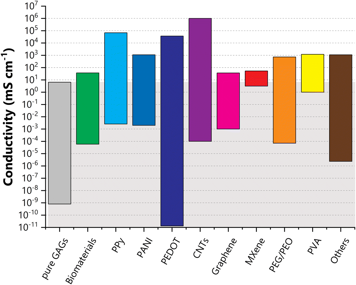 | ||
| Fig. 10 Conductivity values found in the literature for pure GAG materials (in grey), as well as GAG associations with biomaterials (green), conductive polymers (poly(pyrrole) (PPy) in light blue; poly(aniline) (PANI) in blue; poly(3,4-ethylenedioxythiophene) (PEDOT) in dark blue); carbon nanomaterials (carbon nanotubes (CNTs) in purple; graphene and derivatives in magenta; MXene in red), poly(ethylene glycol) (PEG)/poly(ethylene oxide) (PEO) in orange; poly(vinyl alcohol) (PVA) in yellow; and other precursors in brown. | ||
By themselves, GAG materials can reach conductivities up to almost 101 mS cm−1. As it can be seen in Fig. 10, practically any type of material can be used to enhance the conductive properties of GAGs. Even so, not every system will benefit from this association, since variables such as the specific interaction between each component of the system or even the intended application of the prepared materials also need to be taken into account. As an example of the latter, skin conductivity varies from 1 × 10⁻⁴ to 2.6 mS cm−1,332 so a material intended for wound healing does not need to be much more conductive than the above values to promote wound regeneration and repair.
Another point to keep in mind is that the variation in conductivity values does not indicate any trend, conductivity-wise, or even the number of papers reporting on the conductivity of these systems. Conductivity has been reported for only three materials containing both GAGs and MXene, all exhibiting similar values (between 0.25 and 53.3 mS cm−1).256,286,310 On the other hand, four papers have also been found reporting the conductivity of GAG/metallic nanoparticles, with values varying between 10−3 and 101 mS cm−1.289–292
In the following sections, we will be looking more closely at each particular set of the aforementioned materials.
7.1. Association with other biomaterials
In spite of the extensive work conducted on associations of GAG molecules with other biomaterials such as CHT, gelatin, collagen, or others, data concerning the conductivity of these systems is rather scarce in the literature. In fact, out of the dozen reports gathered here,47,219,238,248,253,256,270,288,301,308,333,334 about half correspond to materials obtained with the sole purpose of serving as a base material for comparison to further functionalisations.Overall, there is a significant overlap between the conductivities achieved by pure GAG materials and those observed in materials resulting from the combination of GAGs with other biomolecules (Fig. 10). Such an outcome is to be expected, given the provenance of the precursors, and one might be tempted to note that these combinations might not be very advantageous when considering conductivity gains. Even so, two papers are worth mentioning here, both involving CSA.
In the first one, CSA/hydroxyapatite nanoparticles were incorporated into a CHT membrane.219 The preparation of the CSA/hydroxyapatite nanoparticles took advantage of the strong interaction between the CSA anionic molecule and the dissolved Ca2+ cations145,335 to create a template upon which hydroxyapatite seeds can nucleate and grow. This resulted in plate-like nanoparticles where the hydroxyapatite crystals are oriented along the backbone of the CSA template (Fig. 11). The functionalization of the CHT membrane with these nanoparticles resulted in a steady increase in conductivity from 6.44 to 14.6 mS cm−1 for the CHT membrane functionalized with 8% CSA/HAP nanoparticles. This effect was a direct result of the presence of highly anionic groups (such as phosphate and sulfate ions), derived from the presence of the CSA/HAP nanoparticles into the CHT membrane. The introduction of a higher amount of CSA/HAP nanoparticles in the CHT membrane led to a small decrease in conductivity (12.7 mS cm−1), possibly due to particle–particle aggregation and a smaller interaction between the CHT and CSA/hydroxyapatite moieties.219
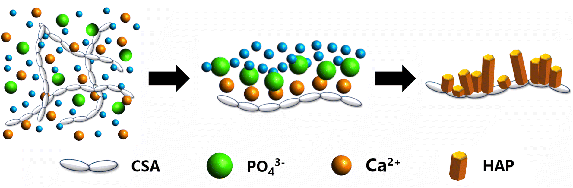 | ||
| Fig. 11 Schematic illustration of the nucleation and growth of hydroxyapatite crystals regulated by CS templates. The strong interactions between the polar groups of CS and the Ca2+ cations facilitate the nucleation of HAP in solution by promoting a high degree of supersaturation. These crystallites will then grow and coalesce to form highly oriented HAP crystallites on the surface of CS. | ||
More recently, Santos et al.47 obtained CSA/CA films from the direct combination of CSA with citric acid (CA), a polyacid that is also known for its cross-linking properties.336 To the best of our knowledge, this is the only report found in the literature where an organic acid was used to improve a GAG's conductivity through direct protonation.47 In an effort to fine-tune the conductivity properties of these films, several CSA:CA ratios were tested. Gains in conductivity up to one order of magnitude are observed at room temperature for CSA/CA films where the CA content is between 60.8 and 82.2% wt. The addition of higher amounts of CA led to phase separation, while the addition of lower amounts of CA did not seem to improve the conductive properties of these materials. Under a saturated RH environment, the conductivity of the 60.8% wt. CA reached 37 mS cm−1, again an order of magnitude higher than the value observed for the CSA precursor under the same conditions.47
7.2. Associations with conductive polymers
Essentially, common conductive polymers, such as PPy, PANI or poly(3,4-ethylenedioxythiophene) (PEDOT) (Fig. 12) are organic materials which possess electrical properties akin to those of metals or inorganic semiconductors. Ever since their discovery in the late 1970s,337 these polymers have successfully been employed in a wide variety of materials, for an increasing number of applications.338,339 Their attractiveness stems from an extremely interesting set of conditions, including lower manufacturing costs, higher mechanical flexibility, better processability and biocompatibility than other materials with similar electrical properties, such as semiconductors or metals. In addition, these conductive polymers also have the ability to attune a diverse set of properties, including hydrophobicity, roughness, oxidation states, exposed chemical groups, easy synthesis and biocompatibility.132,340,341 Their backbone structure consists of a chain of alternating single and double bonds where the highly delocalized charges arising from the formation of π-bonds can move freely. In their natural state, conductive polymers act as insulators. However, their conductivity can increase significantly with dopant concentration and chemical or electrochemical transformations that alter their oxidation state. Oxidation of the polymer chains leads to the formation of a positively charged entity which can then be counterbalanced with a negatively charged dopant to achieve electroneutrality. A vast array of counter-ions can be used for this purpose, from simple halogen anions to complex anionic structures, among which polysaccharides and DNA. Conductivity arises when, once an electrical field is applied, the negative charges of the dopant start moving in and out of the polymer chains, thus breaking the stability of the backbone and allowing the charge carriers to move.132,340,342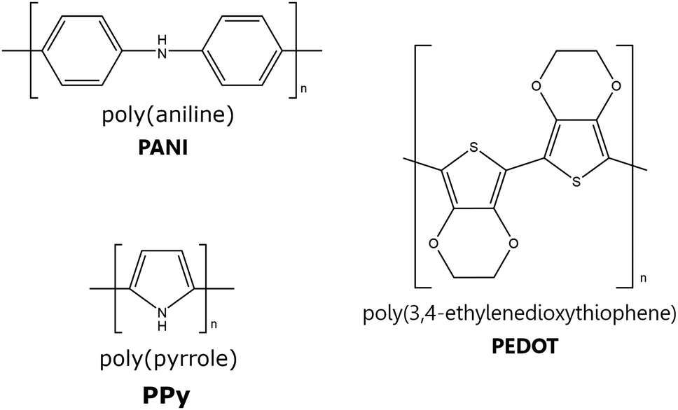 | ||
| Fig. 12 Structural illustration of PEDOT, PANI and PPy. | ||
The combination of PPy and GAGs is a very common procedure, with several papers addressing the conductive properties of the resulting composites with HA,229–239,346–350 CS,231,286,308,309,311,312,350–355 HEP320–329,356–363 and DS.364 Regarding GAG-containing composites, the PPy/GAG systems, where GAG = HEP and HA, are the most widely studied, with the work reported on various PPy/GAG systems allowing important considerations on the role of the dopant in establishing the properties of the final composites.231,342,345,354
HA-based systems. Some studies on PPy/HA films have been devoted to the comprehension of how variables such as molecular weight,348 the degree of sulfation236 or different ratios of PPy/HA229,234,349 affect the overall system. Overall, conductivity measurements performed on PPy/HA films have shown that the conductivity strongly depends on the number, nature, and distribution of the charges on the HA backbone. Films prepared with non-sulfated HA exhibited conductivities of 100–101 mS cm−1,229,230,233 whereas films obtained with sHA (∼2.5–3 sulfate groups per repetitive unit, a degree of sulfation comparable to that of HEP) possess a conductivity on the order of about 103 mS cm−1 (Table 9).230
However, even though sulfate groups are known to enhance the conductivity of HA films, the PPy/HA ratio seems to be just as (if not more) important. Indeed, films obtained from a 0.33 mg mL−1 sHA solution had a conductivity of 3.44 × 10³ mS cm−1, while films produced from a 0.9 mg mL−1 solution of sHA had a conductivity of only 0.9 × 10³ mS cm−1.230 The former value is in line with reports for HEP/PPy films (Tables 9 and 10).320 Moreover, Cen et al.236 reported the preparation of a PPy/HEA/sHA (HEA = 2-hydroxyethyl acrylate) film where the sulfation of HA was performed in an alkaline medium with the biomolecule already immobilised in the acrylate-functionalized PPy matrix. The resulting film had a conductivity of (7 ± 2) × 103 mS cm−1, even though the sHA had a sulfation pattern of approximately 1 sulfate group per disaccharide unit. Although this sulfation pattern is markedly lower than that of the sHA systems previously discussed,230 its conductivity is still approximately twice as high as than that observed for the other systems. This difference might be explained by the preliminary acrylate functionalization of the PPy moiety, which prevented the direct anchoring of HA onto the PPy surface, thus enabling the preservation of the surface integrity and the intrinsic properties of the PPy fibres.235,236 In this aspect, it has been pointed out that the entrapment of biomolecules during the electropolymerisation process leads to a series of constraints for the biomolecule, such as a more hydrophobic environment or even steric constraints which might limit the degree of conformational freedom of the biomolecule.365,366 When compared with the conductivity of non-sulfated PPy/HEA/HA films obtained by the same process (≥(44 ± 1) × 103 mS cm−1),235 the conductivity for this PPy/HEA/sHA is significantly lower, which has been attributed to the presence of OH− anions during the sulfation process.235
In a more recent study, conductivities on the order of 102 mS cm−1 were measured for PPy films containing dopamine (DA)-modified HA, PPy/(HA–DA) (Fig. 13). The highest conductivity was achieved for the film with a PPy:(HA–DA) ratio of 8:1.233 The same film was also superior, conductivity-wise, to the film obtained from unmodified HA, but only when conductivity measurements were conducted under atmospheric conditions. Indeed, when measurements were performed under a humidity-saturated environment (RH = 100%), the more hydrophobic character of the PPy/(HA–DA) 8:1 film became prominent (Fig. 13b). Higher amounts of HA–DA (PPy:HA–DA ratios of 2:1 and 5:1) resulted in less conductive films when compared to either the 8:1 PPy/(HA–DA) film, or even the parent PPy/HA film (Fig. 13a), due to a combination of several factors, including the formation of less cohesive structures, the lower PPy content, and the higher DA content, which has been related to possible covalent bonding or π–π interactions between the DA and PPy moieties, which might interfere with the charge transfer.367,368 Measurements of conductivity as a function of film deformation were also performed for the same batch of materials, and once again, the PPy/HA film proved to be more stable compared to the PPy/(HA–DA) films, with a conductivity shift from 11 mS cm−1 at 0% deformation to 1.5 mS cm−1 at full deformation. The series of PPy/(HA–DA) films revealed decreases in conductivity for deformations of at least 25%. This behaviour was particularly impressive for the PPy/(HA–DA) 8:1 film, which suffered a decrease of 3 orders of magnitude, shifting from 2.4 × 101 at 0% deformation to 2.8 × 10⁻² mS cm−1 at 26% deformation, a result that was attributed to a high PPY content and therefore to the resulting stiffness of the film (Fig. 13c).
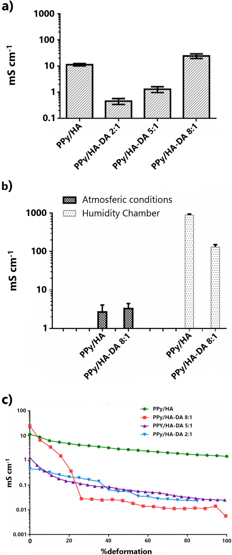 | ||
| Fig. 13 (a) Conductivities of PPy/HA and PPy/(HA–DA) films on a poly(dimethylsiloxane) substrate. (b) Conductivities of PPy/HA and PPy/(HA–DA) 8:1 films under different humidity conditions. (c) Conductivity as a function of applied stress; conductivity measurements are shown as the mean and standard deviation of n = 3. Reproduced, with adaptations, from ref. 233 with permission from Elsevier; copyright © 2017 Elsevier B.V. | ||
HEP-based systems. Early work performed on PPy/HEP systems involved mostly the incorporation of HEP into a PPy film and the study of its properties.357,358 Overall, the conductivity of known PPy/HEP films falls within the range of 10−4 to 103 mS cm−1 (Table 10),320–329 placing these materials at the same level, conductivity-wise, of the PPy/HA systems (Table 9). To the best of our knowledge, the best conducting PPy/HEP system thus far reported was obtained through the functionalisation of PPy with poly(ethylene glycol) methacrylate, followed by activation with cyanuric chloride and the subsequent HEP immobilisation. The resulting films had conductivities varying between (9.5 ± 2) and (8.9 ± 2) × 103 mS cm−1, for HEP contents of 0.5 and 5% vol, respectively. These results correspond well with the conductivity of the HEP-free film (11.7 ± 2) × 103 mS cm−1.324,325 In this case, the preliminary acrylate functionalization of PPy ended up being beneficial since it allowed both the preservation of the intrinsic properties of PPy and a more benign environment for HEP.365,366 The result is a film with no significant hindrance in its conductive properties, even when the amount of HEP is increased 10-fold.
Meng et al.321 directly introduced HEP during the polymerization process of PPy. The resulting particles, with a HEP-content of 0.05 to 0.5% wt, exhibited conductivities between 3.14 and 0.96 × 10³ mS cm−1. These particles were then immersed in a poly(L,L-lactide), PLLA, solution to produce (PPy-HEP)/PLLA membranes. Their conductivity ranged from 37.7 to 3.8 mS cm−1, for the PPY/HEP particles containing 0.05 to 0.5% wt HEP. When the electrical stability of these membranes was studied, a sharp decline in their conductive properties was observed after 50 h. Even so, this dampening was more pronounced for HEP-free and low-HEP content membranes than for those with higher amounts of HEP. By the end of the 500 h-test, the remaining conductivity for these membranes was 8, 9 and 25% of their initial values.
In 2006, Shi et al. used HEP as a soft-template for the preparation of PPy composite nanowires with 90–100 nm-diameter.322 HEP was found to act both as an anion dopant and as a morphology directing agent (Fig. 14a). The results suggested that the formation, size, and even the conductive properties are highly dependent on the Py:HEP ratio. Higher PPy content led to the preparation of longer and more conductive nanowires.
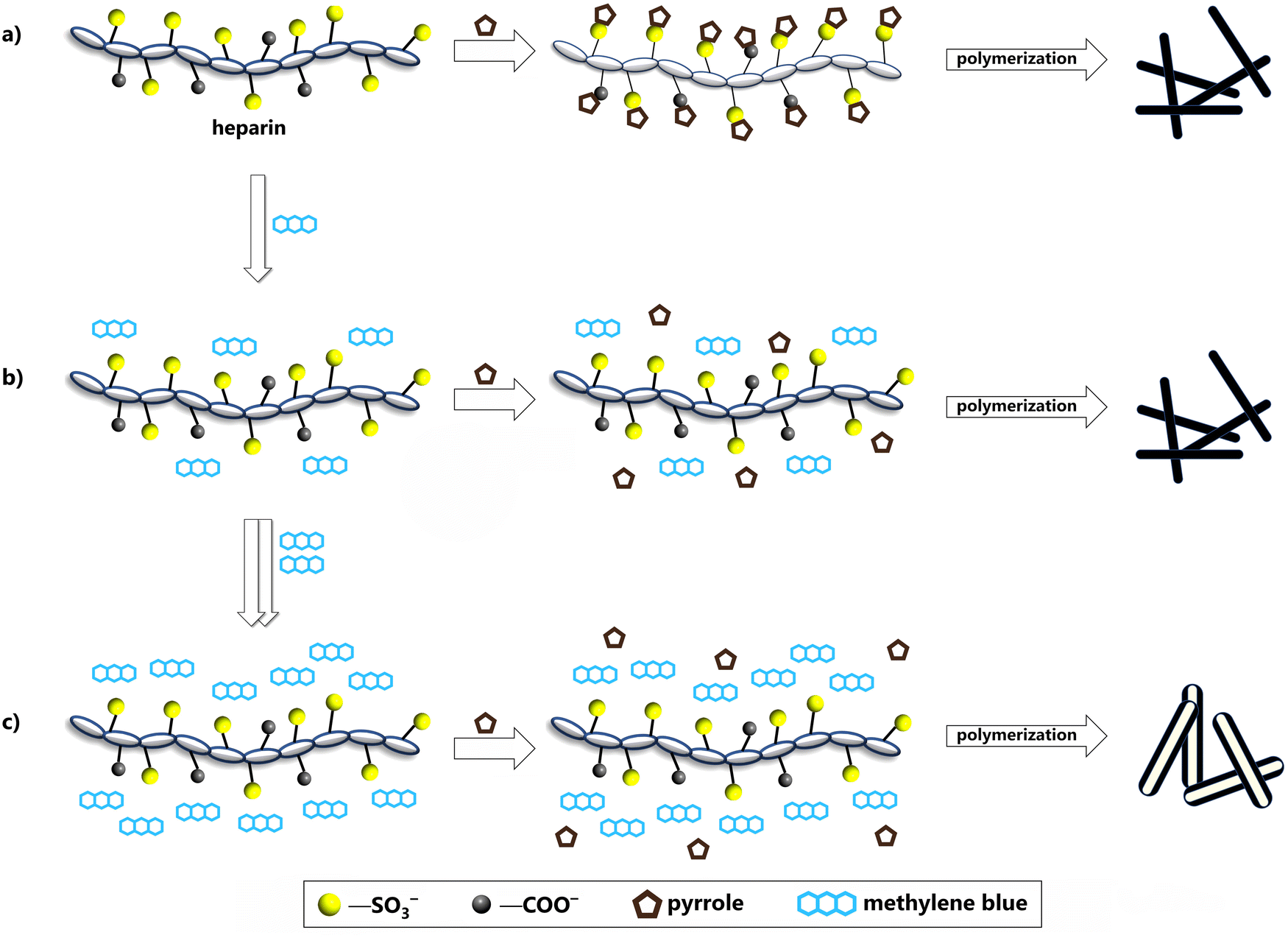 | ||
| Fig. 14 (a). Simplified schematic representation of the possible mechanism for the formation of nanowires from the reaction of HEP with PPy. (b) and (c) Effect of the introduction of methylene blue into the system: (b) a small amount of methylene blue will still lead to the formation of nanowires, while (c) a higher methylene blue content will lead to the generation of PPy nanotubes. | ||
The presence of methylene blue (MB) introduced further complexities, with the possible formation of PPy nanowires or nanotubes (Fig. 14b and c).323 The end product is highly dependent of the concentration of MB in solution, with a high amount of dye effectively blocking access by the pyrrole moieties to the HEP polyanion due to the electrostatic interactions between MB and HEP (Fig. 14b and c).323,362 The pyrrole will then polymerize around the MB/HEP structure, creating a hollow structure, due to the consequent decomposition of the MB/HEP template in the later purification stages. It was also noted that the HEP:MB ratio impacts the properties of the resulting nanofibers, with a higher polysaccharide content leading to thinner nanowires and, therefore, higher surface areas.362 A higher HEP:MB ratio also implies a higher number of HEP functional groups being available for direct interaction with the pyrrole monomers. This explains why the conductivity is higher for the nanorods (6.9 × 10³ mS cm−1), as opposed to the nanotubes (σ = 3.5 × 10³ mS cm−1). Higher conductivities were still observed for PPy networks (34.5 × 10³ mS cm−1), arising from the interconnectivity of the various (HEP-MB)/PPy nanorods under specific synthetic conditions, which were due both to a higher surface area, as well as a dampening of the effect of the insulated terminal cavities.230
CS-based systems. CS was used as the sole stabiliser and dopant in the preparation of PPy-coated silica core–shell particles (SiO2@PPy).286 Basically, CS was pre-adsorbed onto the silica surface, taking advantage of the electrostatic interactions between the negatively charged polar groups of CS and the surface silanol groups, thereby creating a microenvironment capable of stabilising the particles in aqueous media. It was found that the pre-adsorbed CS could control the growth of the PPy shell, with thicker layers of CS leading to thinner PPy shells, therefore impacting the structure and properties, like water dispersibility and conductivity, of the prepared core–shell particles. Thus, the optimization of the conductive properties of the SiO2@PPy nanoparticles requires an appropriate balance between the CS and PPy content. The highest conductivity, 6.9 × 10³ mS cm−1, was achieved for a PPy content of 24% wt (which corresponds to a 11 nm thick layer of PPy). Samples possessing either a lower or a higher amount of PPy invariably exhibited conductivities in the range of 0.4–0.8 × 10³ mS cm−1.286
As anionic polysaccharides, GAGs are attractive options for templates in the preparation of PANI-composites due to the significant number of strong acidic groups which can act as dopant moieties.264,371,372 Notwithstanding, only a handful of papers226,262,264–267,319,333,373,374 reported on the conductive properties of GAG/PANI materials (Tables 9 and 10).
Out of these reports, one concludes that the materials with the highest reported conductivities were both obtained through the polymerization of an aqueous solution of aniline in tandem with a GAG. In one of the first papers on GAG/PANI composites, the protonated form of CSC was used in the polymerization of an aniline solution to produce a film with a conductivity of 68 mS cm−1 (Table 10).319 In a more recent study, Jasenska et al.265 have prepared HA/PANI films out of a colloidal PANI dispersion in a HA aqueous solution with a conductivity of 1.1 × 10³ mS cm−1 (Table 9). On the other hand, Roshanbinfar et al.,333 obtained PANI/(collagen-HA) fibers by electrospinning a solution obtained from the mixing of previously prepared PANI dissolved in dimethylsulfoxide into 9:1 weight collagen/HA formic acid solution. The resulting materials exhibited conductivities between 0.7 ± 0.2 and 2.0 ± 0.6 mS cm−1, with increasing amounts of PANI (Table 9).
A similar system was presented by Thrivikraman et al.264 Here, sHA and collagen/sHA layers were applied as a coating to a PANI film. The resulting films showed conductivities in the range of 10−2 and 100 mS cm−1, respectively. sHA was also used by Wu et al.262 to build poly(acrylamide)/sHA films with different poly(acrylamide):HA mass ratios, which were then combined with PANI. The introduction of PANI led to an increase in the conductivity of the resulting film from negligible to values between 0.6 and 1.05 mS cm−1, with the conductivity growth being a direct consequence of the increase in the degree of sulfation of HA. Compared to the conductivities of the PPy/sHA systems (∼103 mS cm−1),230,236 the results reported for PANI films are quite inferior, since they are of the same level of magnitude of the conductivities reported for PANI/HA materials, in spite of the added advantage of the sulfate functionalization of HA. Still, in both cases, less conductive polyelectrolytes, like poly(acrylamide) and collagen, were selected and used, which might account for the results here discussed, especially since, at least as in the case of Wu et al.,262 an enhancement in the conductive properties is observed with an increase in HA's degree of sulfation.
The use of biomolecules in the functionalization of PEDOT is becoming increasingly popular.376–379 GAGs have also been a part of this research effort, with several reports on the electroactive properties of GAG/PEDOT systems, where GAG is either HA,240–252,378,380 CS189,242,313–315,381,382 or HEP.242,330,340,383 A significant part of these reports provide impedance and/or capacitance data rather than actual conductivity data for their systems.189,241,340,380–384 Even so, an increase in conductivity has usually been observed to occur after the introduction of GAGs to the PEDOT moiety.340,380–383
Generally speaking, the conductivity of GAG/PEDOT materials is in the range of 10−3–103 mS cm−1,240–252,313–315,330,378 which aligns well with what has been reported for either PPy or PANI GAG systems (Tables 9, 10 and Fig. 10), as well as other polysaccharides.377,378,385,386 For example, conductivities for PEDOT-related systems containing dextran sulfate or sulfated cellulose were 7 ± 1 × 10³ and 5.76 × 10² mS cm−1, respectively.387,388 Commercially available pristine PEDOT:PSS (where PSS is polystyrene sulfonate) has a conductivity ranging from 100–103 mS cm−1,242,376,389 which is on par with the conductivities observed for most of the PEDOT:GAG systems reported (Tables 9, 10 and Fig. 10). However, superior conductivities can easily be achieved by post-treating the PEDOT:PSS films with secondary dopants (e.g. salt solutions, ionic liquids, polar organic solvents or strong acids).376,389 The resulting materials exhibit conductivity enhancements by several orders of magnitude, easily reaching values ∼ 102–105 mS cm−1 or even higher.242,376,378,389
According to Mantione et al.,242 conductivity of PEDOT:GAG films (GAG = HA, CSA and HEP), seems to be dependent not so much on the chosen polysaccharide—and hence the number of sulfate groups present in the backbone chain—but rather on how each GAG interacted with the (P)EDOT entities in solution. For this series, the conductivity decreased in the order HA > CSA > HEP for films with the same GAG/PEDOT weight ratio, with the lower conductivities observed for the HEP films being attributed to a poor dispersion in solution and the low stabilisation provided by the HEP template.242
To date, the highest conductivity observed for a GAG-containing PEDOT system was measured with HA-stabilized PEDOT:Tos (Tos = iron(III) p-toluenesulfonate hexahydrate). The films obtained from this material exhibited conductivities ranging between 9.0 and 37 × 103 mS cm−1, depending not only on the amount of the Tos dopant but also on the amount of added HA (Fig. 15).247 Even though the greatest contribution to PEDOT:Tos/HA conductivity comes from the PEDOT:Tos component, the presence of HA was, overall, found to be beneficial. This effect was particularly noticeable for a PEDOT:Tos molar ratio of 1:0.5, where the conductivity of the resulting HA-stabilized material practically doubled when the HA content was raised from 0.2 to 1.0% wt. But even for higher Tos amounts (PEDOT:Tos molar ratio of 1:2), an increase was still observed, from 31 to 37 × 103 mS cm−1, with a threefold increase in HA content from 0.2 to 0.7% wt (Fig. 15).247
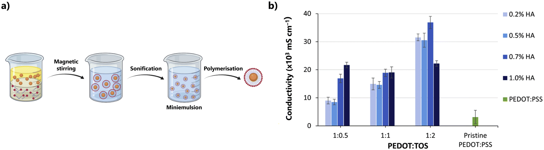 | ||
| Fig. 15 (a) The preparation of the prepared HA-stabilized PEDOT:Tos nanoparticles was achieved by the formation of a microemulsion of HA and EDOT, upon which iron(III) p-toluenesulfonate and hydrogen peroxide were added. (b) The conductivity of the prepared HA-stabilized PEDOT:TOS and pristine PEDOT:PSS films was determined using the Van der Pauw equation. Reproduced from ref. 247; copyright © 2022 The Author(s). Published by Elsevier Ltd. This work is licensed under a Creative Commons Attribution 4.0 CC-BY International License. | ||
The preparation of PEDOT/HA nanoparticles, also through chemical oxidative polymerization, resulted in a material with a conductivity of 360 mS cm−1,240 an order of magnitude higher than the most common results (Tables 9 and 10) and comparable to the conductivity observed for sulfated cellulose.388 Incorporation of these nanoparticles into either a poly(L-lactic acid) (PLA) or CHT/gelatin matrix led to materials with conductivities of 4.7–69.4 and 3.91 × 10⁻²–2.91 mS cm−1, respectively.240,241 The higher conductivity observed for the PLA-containing PEDOT/HA nanoparticles is due to a higher content in nanoparticles, since similar amounts of loading (10% PEDOT/HA nanoparticles) led to materials with similar conductivities (4.7 and 2.91 mS cm−1 for the PLA and CHT/gelatin matrices, respectively).240,241 Upon hydration, both materials displayed different conductive behaviours. Hence, while the conductivity of the PLA composite slightly decreased, the conductivity of the CHT/gelatin scaffold materials increased threefold. Indeed, values obtained for the 10% PEDOT/HA incorporation into the CHT/gelatin scaffold varied from 2.91 to 9.48 mS cm−1 for the dry and wet materials, respectively, with other nanoparticle loadings also displaying a similar variation.241 These variations seem to be related to the specific interaction between the polymeric matrix and the hydration H2O molecules, with the PLA matrix being more hydrophobic than the CHT/gelatin one and thus less susceptible to conductivity variations.240,241
More recently, Leprince et al.,251 designed a HA derivative with the intention of mimicking the PSS chemical functions, thus serving as a more efficient dopant for the PEDOT chains (Fig. 16-Ia). To this end, both sulfates and phenylboronic acid (PBA) groups were introduced into the polysaccharide skeleton to form a sHA-PBA hydrogel with a degree of sulfation of 4. The resulting PEDOT:(sHA-PBA) film exhibited a conductivity of (1.6 ± 0.2) × 103 mS cm−1, which was far higher than the conductivity observed for PEDOT:HA films when the HA possessed either sulfate groups (PEDOT:sHA, between 32 ± 7 and 160 ± 40 mS cm−1, depending on the degree of sulfation) or the PBA moieties (3.5 ± 0.9 mS cm−1) (Fig. 16-II). The observed enhancement in conductivity was possible due to a synergistic effect arising from both an overall net charge increase (due to the presence of the sulfate groups), and an increase in the hydrophobic π-stacking interactions with PEDOT.
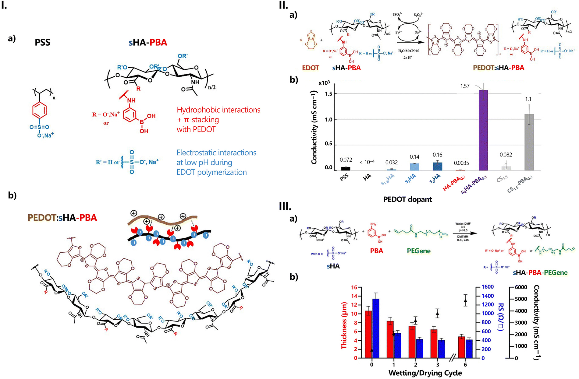 | ||
| Fig. 16 (I) Design of sHA-PBA derivatives (a) mimicking the PSS structure and (b) act as optimal dopants for PEDOT. (II) Synthesis and conductivity properties of cross-linked PEDOT:HAS-PBA films: (a) reaction scheme and (b) conductivity measured using a four-point probe (values are compared to those of a commercial PEDOT:PSS ink (Clevios PH1000) prepared in PBS buffer at pH 7.4 and the prepared PEDOT:CS derivatives) (III) Synthesis and conductivity properties of cross-linked PEDOT:HAS-PBA-PEGene films: (a) functionalization of HAS-PBA with PEGene; (b) effect of wetting and drying cycles on the conductivity and thickness of cross-linked PEDOT:HAS-PBA-PEGene/PEG films. Reproduced from ref. 252 with permission from The Royal Society of Chemistry, copyright © 2023. | ||
This composite was further enhanced with the introduction of PEGene, an alkene-functional poly(ethylene glycol) derivative (Fig. 16-IIIa).252 The resulting PEDOT: (sHA-PBA-PEGene) film more than doubled the conductivity of PEDOT:(sHA-PBA), reaching a value of 3.8 × 10³ mS cm−1. The cross-linking of this composite with PEG-(SH)2 led to an initial decrease in conductivity to 600 mS cm−1, which then rebounded to 4.6 × 10³ mS cm−1 after a series of wetting/drying cycles (Fig. 16-IIIb).
7.3. Associations with carbon nanomaterials
Carbon nanomaterials have various forms and diverse allotropes (Fig. 17).390 These materials possess an impressive array of attributes, such as exceptional electrical conductivity, mechanical and optical properties, and thermal stability. It is thus not surprising that these materials have attracted significant attention across a wide range of fields (e.g.: electronics, energy, membranes, biomedical sciences, and catalysis).390–392 Of particular interest to the present discussion are carbon nanotubes (CNTs), and graphene and its derivatives which have been used in the preparation of GAG-related materials (see Tables 9, 10 and Fig. 10).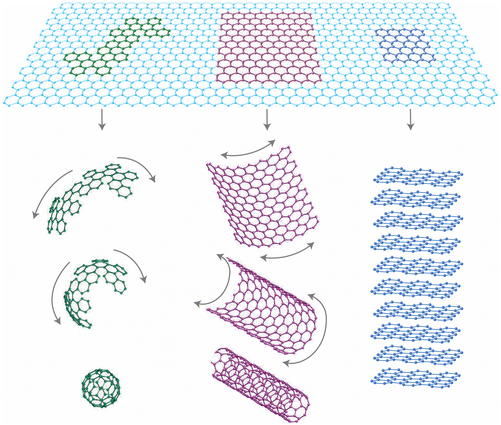 | ||
| Fig. 17 Graphene as the building block for other carbon allotropes. It can be wrapped up to form fullerenes (in green), rolled up into carbon nanotubes (in violet), or stacked up to form graphite (in blue). It can be wrapped up into 0D buckyballs, rolled into 1D nanotubes, or stacked into 3D graphite. Reproduced from ref. 393 with permission from Springer Nature, copyright © 2007. | ||
000 cm2 V−1 s−1). On the downside, graphene also features low intrinsic electrical noise, making its conductance highly sensitive to local electrical and chemical perturbations.394,398One of graphene's major disadvantages is its inability to be properly dispersed in polar solvents due to its surface inertness and strong cohesive interlayer energy.394,395 This can be easily overcome through oxidation, to form graphene oxide, GO. GO can be further modified through reduction to form reduced graphene oxide, rGO. Both derivatives, GO and rGO, contain various oxygen-containing functional groups (hydroxyl, carbonyl, carboxyl, and epoxy), which not only provide an increased hydrophilic character to the material, as evidenced by its dispersibility in water, but also facilitate the integration of a wide range of entities, among which polyelectrolytes and biomolecules, via non-covalent interactions such as electrostatic interactions, van der Waals forces, hydrogen bonding, and others.394,398
Besides solvent dispersibility, both GO and rGO exhibit excellent electrical, optical, and mechanical properties.398 Even so, their properties are different from those observed for their parent structure. Due to the high number of functional groups and, hence, structural disorder, GO has a much lower conductivity than graphene.399,400 Improvement of its conductive properties is deeply related to the restoration of the primitive graphene structure and, hence, the removal of the polar functional groups. Due to its high surface activity,400 a significant part of these functional groups can be easily removed through chemical and thermal processes, or a combination of both.399,401 Even so, this is not a trivial process, with different reduction procedures leading to materials with different results.402 Hence, the properties of rGO are a direct result of the quality and type of the reduction process. In reality, since the reduction of GO is only able to partially restore the graphene structure, properties like charge mobility and electrical conductivity, while better than those of GO, are still worse than those observed for its graphene precursor.399,401
By imparting new functionalities and purposes to the graphene nanostructure, chemically-modified graphene materials have become of considerable importance to the chemical and materials communities.396
Among the plethora of materials that can be used to functionalize graphene, GO and rGO are polysaccharides and, as might be expected, GAGs.403–405 HA and HEP, in particular, are known for their various functions, such as surface coatings,406–408 cross-linkers409 and reducing agents for GO.331,410,411 On the other hand, incorporation of graphene or its derivatives into GAG-related materials is seen as an efficient way to improve the thermal, mechanical, and conductive properties of these biomatrices.270–272,316,408,412 Computational work performed on HA/graphene interactions indicates that these functions seem to depend on C–H⋯π and O–H⋯π interactions between HA and graphene moieties, while interactions with GO rely mostly on the functional groups present on the graphene surface.413
As far as conductivity studies are concerned, GO316,408 and rGO,270–272,331,412,414 have been the most popular choices, notwithstanding reports with graphene408 and sulphonated graphene415 also being known. The available conductivity data in the literature for these systems points to values in the range of 10−3 to 101 mS cm−1 (Tables 9, 10 and Fig. 10).270–272,316
The material exhibiting the highest conductivity combines CS-methacrylate with a methoxy poly(ethylene glycol)/poly(ε-caprolactone) (PCL) conjugate and GO to form a porous scaffold.316 Conductivity was observed to be a direct consequence of the presence of GO, with the authors reporting the conductivity of the graphene-free polymeric mixture to be undetectable. The optimal conductivity (18.4 mS cm−1) was found for a 3% wt. GO addition, with higher amounts leading to lower values due to an aggregation effect, as is typical of carbon nanomaterials.316
HA has been involved in the preparation of a few polymeric matrices, which would then be combined with rGO.270–272 The measured conductivities for all of these materials were on the order of 10−3 mS cm−1 and always dependent on the rGO concentration.270–272 In one particular case, a HA/DA hydrogel was combined with poly(dopamine)-coated rGO to produce a composite for wound healing.270 The conductivities of the prepared dried hydrogels varied from 0.3 to 2.5 × 10⁻³ mS cm−1 (for the graphene-free hydrogel and the 5% wt rGO addition, respectively). However, upon wetting, the same hydrogels showed a significant increase in conductivity, between 0.53 and 0.57 mS cm−1, regardless of the presence of rGO. This 1000-fold increase is a direct consequence of the ionic conductivity of the polyelectrolytic matrix, which means that HA is at least partially responsible for this conductivity enhancement since poly(dopamine) is also known to be significantly affected by high humidity conditions.416
HEP-coated GO was combined with poly(L-lysine) via a layer-by-layer (LbL) deposition method onto poly(ethyleneimine) (PEI) activated surfaces.408 Two different surfaces were tested: a 2D silicon wafer (Fig. 18a) and a 3D electrospun PCL scaffold. For each surface, two different deposition strategies were tested: one from quiescent solutions and the other from hydrodynamic flow conditions. The composites generated from quiescent solutions consistently showed higher resistance to charge transfer than the ones obtained from hydrodynamic flow conditions. This is because flow conditions allowed not only for a better dispersion of the graphene nanomaterials by HEP but also for a higher deposition rate.408
 | ||
| Fig. 18 (a) Schematic representation of the preparation of a GO/HEP and poly(L-lysine) layer-by-layer film on a PEI-activated silicon wafer. (b) Sheet resistance of self-assembled graphene–PEMs of different terminating surfaces and layer number of heparin (H) or poly-L-lysine (P) (n = 4, error bars show the standard deviation). (c) Contact angle values for heparin (H) and poly-L-lysine (P) terminating LbL surfaces using 0.15 mg mL−1 GO (closed circle) and 0.5 mg mL−1 GO (closed triangle), compared to graphene-free surfaces (open square) (average of 3 readings for each point, error bars show standard deviations). Partially reproduced from 408 with permission from The American Chemical Society. Copyright © 2012. | ||
In particular, a significant reduction in the sheet resistance was observed between the first and second LbL deposition cycles on the PEI-activated 2D silicon wafer (Fig. 18b). Further reductions were observed with the deposition of additional layers, with the sheet resistance values stabilising around the sixth LbL cycle (Fig. 18b). The conductivity of this polyelectrolyte multilayer film is directly connected with the presence of graphene, with a higher amount of graphene leading to a higher conductance of the material. The conductive properties are also dependent on the composition of the film's top layer, with charge transfer being facilitated when the top layer is composed of GO/HEP (Fig. 18b). An added feature is the film's consistently more hydrophobic character—in particular when compared with the GO-free multilayer films—when the top layer comprises GO/HEP (Fig. 18c). This is even more interesting given the inherent hydrophilic character of both GO and HEP, again highlighting GO's role in the conductive properties of these materials.408
The assembly of the multilayer coating on the PEI-activated PCL electrospun nanofibrous scaffold led to the diffusion of graphene nanomaterials through the pores on the scaffold into the individual nanofiber scaffolds. The final conductive properties were dependent of the type of scaffold used to perform multilayer coating. Randomly aligned fibres still exhibited an anisotropically high sheet resistance at the end of six complete LbL cycles (203 kΩ sq−1), while the aligned fibres had a parallel resistance of 109 kΩ sq−1 and 408 kΩ sq−1 when measured in a perpendicular and parallel orientation.408 Regardless of the substrate, a further enhancement in the conductive properties of both composites was observed after a post-annealing thermal treatment.408
Overall, their electronic properties are dependent on structural features (length, tube diameter, wall thickness, and geometry) and range from metallic to semiconductor, depending on the chirality along the graphene sheet.391,395,417 Conductivities of SWCNTs have been reported to be as high as 106 or 108 mS cm−1 for SWCNTs and 105 mS cm−1 for MWCNTs. Nonetheless, these conductivities can be hindered by several issues, such as the presence of various defects and impurities acquired during the synthetic procedures, contact between CNTs (arising from aggregation issues due to intense inter-tube van der Waals forces, which then leads to a build-up of resistance at the junctions of overlapping CNTs) or ambient effects.395,417 As such, a preliminary step where the CNTs are appropriately dispersed in a matrix is required for the proper exploitation of CNTs in composites.
GAG/CNT composites initially emerged from the need to find suitable surfactants in an aqueous medium.279,280,418 HA was the first GAG to be tested and it was found to be a suitable dispersant for CNTs.279,280,418 HEP,419 CSA, CSC and DS,420 soon followed, with varying results. Like HA, CSA and CSC have been shown to be good dispersants and cross-linkers of SWCNTs, preserving both their mechanical and electrical properties.420 HEP has been reported as having a good selectivity for larger nanotubes but not for shorter ones.419 In contrast, DS has been considered a poor surfactant agent for SWCNTs.420 At the root of these results lies the way GAGs interact with water, extending more or less in accordance with the number and position of polar groups presented in its structure and the H-bonds these groups establish with the solvent (Section 2.2).419,420 The molecules with the best performance seem to be the ones with the least number of sulfate groups per disaccharide unit (HA, with zero sulfate groups, and CSA and CSC, each with one sulfate group) and which are capable of better conforming to the structure of the CNTs. On the other hand, HEP, with its three sulfate groups and a more rigid structure in solution, is capable only of interacting with the larger SWCNTs, indicating its selectivity. In this context, it is interesting to note that DS, which also possesses one sulfate group per disaccharide unit (located in the same position as the sulfate group of CSA) is less efficient in dispersing SWCNTs in solution.420 This happens because the carboxyl group is positioned in a different position than in CSA, and stronger Coulombic interactions between the disaccharide units are established, again as opposed to what happens in CSA, which leads to a smaller, more compact configuration.420
The conductivity of GAG-containing matrices with CNTs is routinely on the order of 102 to 105 mS cm−1 (Tables 9, 10 and Fig. 10), placing these materials among the GAG-related materials with the highest conductivity.277–284,317,318 These high conductivities are usually attributed to the presence of CNTs, regardless of the type of nanotube employed.
Be that as it may, GAGs have also been found to contribute to the overall conductivity of the prepared composites, in much the same way as was observed for graphene (Section 6.3.1): as anionic polyelectrolytes, they are capable of ionic charge transfer and appropriately dispersing and structuring the CNTs in solution.275–277,421 This means that the GAG:CNTs ratio is extremely important in establishing good conductivity: enough CNTs need to be present so as to reach the percolation threshold and allow the formation of a conductive path for electronic charges, without leading to CNT aggregation.
A significant portion of the GAG/CNT materials with reported conductivities are in the form of nanofibers, obtained by the wet-spinning process. In this process, the CNTs are dispersed in an aqueous solution containing either HA275–282,284,422–424 or CSA,318,425 which is then injected into a coagulation bath. Although this process has been shown to lead to materials with lower conductivity,284,426 conductivity on the order of 105 mS cm−1 has been easily reached.279–283 The coagulation bath has also been shown to affect the conductivity of these materials, with an acidic aqueous coagulation bath providing better results, conductivity-wise, when compared with other possibilities, such as a CHT aqueous solution or the use of non-aqueous media.282 In this aspect, in a very curious experiment, SWCNTs dispersed in a HA solution followed by immersion in a CHT coagulation bath have achieved a conductivity ((1.35 ± 0.15) × 105 mS cm−1) 2 orders of magnitude higher than that of nanofibers obtained from the dispersion of SWCNTs in a CHT solution and a coagulation bath containing either CSA ((2 ± 0.02) × 103 mS cm−1) or HEP ((1 ± 0.04) × 103 mS cm−1).279
These nanofibers can also be subjected to further processing. One such example is the preparation of a core–shell nanofiber by electrodeposition of a PANI coating on HA/SWCNT nanofibers prepared by a wet-spinning process.278 Up to three coatings of PANI were applied to the nanotube composite, with conductivity consistently increasing from 25 to 59 × 103 mS cm−1. No data were presented on bare HA/SWCNTs. This conductivity enhancement is due to the establishment of H-bonds between the polar groups of the HA/SWCNTs and the amine groups in the PANI polymer. However, with the continual deposition of PANI, the deposition started to shift from an H-bond interaction to a physical surface adsorption, which weakened the charge transfer ability. Consequently, a shift was observed upon the deposition of the fourth layer, with a decrease in the conductivity to 16 × 103 mS cm−1, a value that is lower than the one obtained by the deposition of a single layer of PANI.278
Recently, HA has been combined with SWCNTs and acrylonitrile butadiene copolymer latex to produce an ionic/electronic conductive film.277 The introduction of a minimum amount of SWCNTs (0.1% wt addition) already led to an impressive increase in conductivity, from a non-conductive material to ca. 10−4 mS cm−1. Additional amounts of SWCNTs (up to 1% wt) further enhanced the conductivity up to ca. 106 mS cm−1, making this film, to the best of our knowledge, the most conductive GAG-containing material reported in the literature. Although these conductivity values are, as expected, strongly dependent of the presence on the SWCNTs, electrical impedance measurements have shown an decrease in the charge transfer interfacial resistance with an increase of the HA loading from 1.4 to 2.6, thereby assessing HA's role as an ionic conductor in this system.277
7.4. Associations with inorganic ionic entities
Inorganic ionic entities, such as the borate anion (B(OH)4−) or the ferric cation (Fe3+), have recently been used as cross-linkers in GAG-containing hydrogels in order to endow the resulting material with self-healing properties. This is due to the ease with which both borate anions (and other boron species) and ferric cations can act as Lewis bases and acids, respectively, in a wide range of electron-rich environments and establish a series of dynamic reversible bonds with the oxo-side groups of these polyelectrolytes.427,428Moreover, being ionic in nature, both entities can also affect the conductive properties of the materials they are part of by acting as charge carriers. This is especially true with the metallic Fe3+ cation, where hydrogel conductivity has been reported to be enhanced with an increase in iron content.429,430 As for the borate anion, conductivity is also affected, but given its complex chemistry in solution,427,431 its impact is not as straightforward as in the case of the ferric cation.
In most of the systems here discussed, the self-healing properties arise from the presence of borate anions,254,260,261 that were invariably sourced from borax (sodium tetraborate).
Borax is known for its fast hydrolyzation and its ability to readily form borate anions in solution. Most importantly, borax is known for the ease with which it forms ester bonds with diol species, reacting with up to four different hydroxyl groups at a time. With polysaccharides, and indeed other polyelectrolytes, this allows the opportunity for cross-linking to occur, even at low concentrations.432–435
Tao et al.260 have reported on a simple hydrogel obtained by reacting HA with borax in a sodium nitrate (NaNO3) aqueous solution. The hydrogel has a conductivity of 44.9–61.7 mS cm−1, depending on the NaNO3 content. Even without the conductivity values for the borate-cross-linked HA hydrogel, it is safe to admit the dominant contribution of the NaNO3 electrolyte to the overall conductivity, particularly when keeping in mind the range of conductivities observed for pure HA (Table 8). Self-healing experiments were conducted on the hydrogel with the highest NaNO3 content, and it was observed that the system was able to fully recover from the applied cut and heal. In a similar work, a lithium chloride (LiCl) electrolyte solution was added to a self-adhesive conductive hydrogel consisting of grafted HA via DA, acrylamide, and borax, taking advantage of the extremely high number of catechol, hydroxyl, and polar groups present in the precursors to form not only an extensive network consisting of H-bonds as well as dynamic borate ester bonds.261 The conductivity of the resulting hydrogel was reported to be 0.18 mS cm−1 and increased to 11 mS cm−1 with the addition of LiCl. After the cut and heal cycle, the hydrogel exhibited conductivities of 0.12 and 8.92 mS cm−1, respectively, corresponding to healed conductivities of 66 and 81%.261
DA-functionalized HA was also combined with poly(acrylic acid) and Fe3+ cations to produce a thermoplastic, self-healing hydrogel with a 97% mechanical recovery in 30 s and an electrical recovery of 98% in 2 s (Fig. 19a).436 The conductivity of the resulting polymer was undoubtedly associated with the iron content within, with hydrogel formulations containing the highest iron content showing both the lowest electrolyte resistance and charge-transfer resistance (Fig. 18b).
 | ||
| Fig. 19 (a) Schematic of the synthetic process for the multifunctional conductive hydrogels and the corresponding interactions inside multifunctional networks; (b) electrochemical impedance plot of the hydrogels with different c(Fe3+), and (c) the corresponding equivalent electrical circuit; and (d) images of strain-dependent conductivity performance of the hydrogels. Reproduced from ref. 436 with permission from The American Chemical Society. Copyright © 2019. | ||
8. Applications
Recent advances in electronics and material science, especially in the nanotechnology domain, have opened new horizons, enabling the development of reliable, more sensitive, and less expensive instrumentations. In this follow-up, reports about new electrodes, sensors, analytical, and flexible electronic devices will be highlighted.Nowadays, flexible and/or stretchable electronics are a hot topic with a plethora of potential technological applications, serving as ideal interfaces, bringing together conventional electronic devices and biological systems.437–439 However, flexible electronics devices present some shortcomings (e.g., the device performance may be lower than that of conventional rigid electronics). Even so, the research effort on these energy systems has increased significantly over the last few years, continuously seeking the production of devices with enhanced biocompatibility and environmental friendliness. In this context, the device is required to be human-friendly and deformable enough to be able to conform, adapt, and attach to the curvilinear shape of biological systems, such as organs and tissues.440,441 This is, in fact, a key property of flexible and stretchable electronics, since it offers a means to bypass challenges posed by rigid electrodes.
Practically, all of the materials presented in Section 7 were obtained or applied in the form of hydrogels. Presently, the use of hydrogels—or more precisely, conductive hydrogels—in flexible electronics stands out as one of the most interesting emerging technologies, not only because of their use as a passive matrix material or as an adhesive layer, but mainly because their potential as a functional material is finally being explored.442–444
As stated in the Introduction, GAGs are predominantly used in biomedical research, where they have found extensive applications in areas such as tissue engineering and regenerative medicine, therapeutics delivery, and others.43–45,57,445,446 Their success as materials of choice is rooted in three key properties: biocompatibility, biodegradability, and versatility. However, as highlighted in the preceding sections, not all GAGs evoke the same interest when it comes to the study and application of their conductive properties. Out of the whole family of materials, HA immediately stands out as the one that gathered the most research interest, with CS and HEP a distant second group and research on the remaining GAGs being practically inexistent in the context discussed herein. Although there are several, various reasons for such a preference,58,72,447 it is noteworthy to observe that unlike all other GAGs, HA is both the sole non-sulfated polysaccharide and also the only one that is available from cheaper microbial sources, thus avoiding issues like impurities, structural heterogeneities and uncontrolled amounts of sulfate units, and even a higher cost of use that, unfortunately, are still intrinsic to the other GAGs.448–450
The vast majority of the GAG-related hydrogels referred to in Section 7 were developed with a pharmacological or biomedical perspective in mind. Even so, for the last 7–8 years, reports on the use of GAG-hydrogels as electrical biosensors, strain sensors, or their application in flexible electronics (Tables 9 and 10) have been increasingly showing up. Adding to this are the reports on the use of GAG-containing systems for application in energy devices of current relevant interest, such as fuel cells, batteries, supercapacitors, or solar cells (Fig. 20).
 | ||
| Fig. 20 Typical structures of the four most common applications of polymer electrolytes. Schematic of (a) a battery; (b) a double-layer capacitor; (c) an eletrochromic devices, (d) a hydrogen fuel cell; and (e) a dye-sensitized solar cell. | ||
While some of these systems were developed for incorporation into a flexible device, others were designed with a more traditional application in mind. All of these will be highlighted in the following sections.
8.1. Batteries
The ever-growing demands for energy have spurred continuous research on efficient energy storage systems. Among these, batteries (Fig. 20) are ubiquitous, available in various sizes, shapes, and materials according to their intended applications. Currently, research efforts are concentrated on the optimization of performance, cost, and environmental sustainability. This explains the search for new electrodes, incorporating non-metallic materials and composites with low-internal resistance that can be recovered or recycled with an eco-friendly strategy. Or the investment in new, more eco-friendly electrolytes with wider electrochemical windows and high energy density while minimising risks of portability or leakage.In rechargeable batteries, a complex series of processes need to be addressed, including electrochemical reactions, the diffusion of ions through the electrolyte, followed by the percolation of ions through the electrodes, and the possibility of any undesired side reactions. Along the way, issues might arise, such as solid deposition, corrosion of the electrolyte, changes in diffusivities, or even in the electrolyte itself.
Within this wide, vast body of research, GAGs have been called upon to serve certain, specific crucial functions, playing the role of anionic binders for electrodes in alkali-metal batteries or as electrolyte additives in aqueous Zn batteries.
Ideally, a binder should be as compatible with the electrode material as possible. Its formulation should thus reflect the environment it is inserted in. When considering a hydrophilic setting, the binder should boast an abundance of polar functional groups, such as carboxyl and hydroxyl groups. These functionalities facilitate the establishment of robust supramolecular interactions necessary for preserving the integrity of the electrode. Conversely, in a hydrophobic electrode environment, solely incorporating polar functionalities may prove to be insufficient. Therefore, the binder's formulation demands greater complexity. Indeed, research indicates that multicomponent binders offer a more effective response to the diverse multidimensional requirements of contemporary electrodes. Whether it is accommodating the often-contradictory prerequisites for electronic and ionic conduction or the introduction of additional features such as self-healing, high elasticity, or flexibility, there are great benefits arising from the option of customizable compositions.455,457
Binders for silicon anodes. Silicon (Si) has attracted significant attention as a promising anode material for rechargeable batteries. This is primarily due to its low cost, environment-friendly nature, and unparalleled energy-storage capacity, which far surpasses that of a graphite anode.451,458 Even so, its use in Li-ion batteries has been limited due to some major hindrances, such as the considerable volume expansion variation during long-term cycling (lithiation/delithiation process) and its relatively low conductivity.459,460 The importance of binders for Si-anodes has been highlighted by Kovalenko et al.,461 who demonstrated that an alginate-based binder yielded a reversible capacity eight times greater than that of state-of-the-art graphite anodes. Soon after, various advanced polymeric binder materials were proposed with the goal of overcoming the aforementioned challenges.451,452 In particular, polysaccharide-based 3D binders are considered to be effective in improving the cycle performance of Si anodes and act as an effective buffer for volume expansion.462–464 Pure HEP hydrogels have been shown to underperform as a Si/C electrode binder for Li-ion batteries due to their poor physical properties, which led to a significant drop in capacity retention during the first cycles and full first discharge Li uptake.454 Likewise, pure HA hydrogels have also shown large decreases in their initial capacity values at very low cycles, which in some cases were even lower than the theoretical capacity of a carbon electrode.460,465 All in all, both GAGs performed worse than other polysaccharides, such as carboxymethylcellulose (CMC) or alginate, under the same experimental conditions.454,460 This situation changes, however, when GAG-based hydrogels are combined with other elements, such as functionalizing agents, cross-linkers, or other polymeric entities (Table 11).
| Electrode composition | Initial Coulombic efficiency (ICE) | Cycling performance | Ref. | |||||
|---|---|---|---|---|---|---|---|---|
| Anode | Binder (wt ratio) | Additives | Si:binder:Additive ratio (wt) |
Si mass loading (mg m−2) | Specific capacity (mA h g−1) | Capacity decay rate per cycle | ||
| AA: acrylic acid; AM: acrylamide; CB: carbon black; CMC: carboxymethylcellulose; DA: dopamine; ECH: epichlorohydrin; FM: 2-(perfluorobutyl) ethyl methacrylate; IA: itaconic acid; SBR: styrene butadiene rubber; Si–C: Si carbon coated electrode; Si–Graf: Si–graphite electrode; SiMPs: silicon microparticles; SiNPs: silicon nanoparticles; SiO–Graf: SiO–graphite electrode. SSPS: soluble soybean polysaccharide; and TA: tannic acid. | ||||||||
| SiNPs | (HEP-DA)/CMC/SBR (0.1:0.9:2) |
SuperP | 8:1:1 |
5.0 | 99.7% | 343 (75.3%) at 0.5C/0.2C (charge/discharge), 150th | 138 | |
| HA | SuperP | 8:1:1 |
0.6–0.8 | 85.67% | 1650.1 at 0.1C, 80th | 465 | ||
| HA-ECH | SuperP | 8:1:1 |
1.3 | 92.16% | 3733.1 (70.4%) at 0.5C, 100th | 465 | ||
| 8:1.5:0.5 |
1.3 | 87.89% | 3261.5 (64.6%) at 0.5C, 100th | 465 | ||||
| 88.98% | ||||||||
| 3060.8 (53.3%) at 0.5C, 100th | ||||||||
| 9:0.5:0.5 |
||||||||
| HA-SSPS (1:1) |
SuperP | 6:2:2 |
0.5–0.7 | 92.67% | 1252 (71%) at 2 A g−1, 350th | 0.24% | 222 | |
| (IA/AA/AM/FM)/HA | SuperP | 60:20:20 |
0.5–0.7 | 91.1% | 1461, at 1C, 200th | 294 | ||
| 2.56 | 535, at 0.125C, 200th | |||||||
| Si MPs | HA | SuperP | 3:1:1 (wt) |
0.8 | 347 (12.5%) at 1C, 600th | 460 | ||
| HA-Gallol | SuperP | 3:1:1 (wt) |
0.8 | 85.1% | 1153 (42.5%) at 1C, 600th | 460 | ||
| Si | HA-TA | CB | 6:2:2 |
1.0 | 86.96% | 2512 at 0.1C, 100th | 221 | |
| Si–C | HA-Gallol | SuperP | 3:1:1 (wt) |
680 (89.6%) at 1C, 100th | 460 | |||
| Si–Graf | HA-TA (1:1) |
CB | 8:1:1 |
2.0 | 410 at 0.5C, 300th | 0.36% | 221 | |
| HA-SSPS | 73:15:10:2 (Si:Graf:HA:SSPS) |
2.2 | 390 at 0.3 A g−1, 100th | 222 | ||||
| (IA/AA/AM/FM)/HA | SuperP | 15:73:10:2 (Si:Graf:binder:Add) |
3.84 | 466 at 0.5C, 200th | 294 | |||
| SiO–Graf | HA-SSPS | 73:15:10:2 (Si:Graf:HA:SSPS) |
0.9 | 92.67% | 303 at 0.5 A g−1, 350th | 0.11% | 222 | |
| 2.2 | ||||||||
| 380 (93.1%) at 0.3 A g−1, 100th | ||||||||
| (IA/AA/AM/FM)/HA | SuperP | 15:73:10:2 (Si:Graf:binder:Add) |
3.28 | 404 at 1C, 200th | 294 | |||
For instance, the incorporation of HEP into a CMC/styrene butadiene rubber (SBR) composite yields a binder with enhanced adhesion properties and significantly improves capacity retention. After 100 cycles at a charge rate of 0.5C and a discharge rate of 0.2C, the capacity retention increases to 380 mA h g−1, representing 81.3% retention, compared to the initial CMC/SBR binder, which only retains 62.3% of its capacity (286 mA h g−1).138
The functionalization of HEP with DA via the carbodiimide coupling reaction led to an even better binder, both in terms of adhesion and electrochemical properties. Even though the specific capacity of the (HEP-DA)/CMC/SBR binder was the same after 100 cycles as that of the non-functionalized HEP binder (81.3%; 378 mA h g−1), after 150 cycles, the capacity retention was much greater (75.3%; 343 mA h g−1), with an ICE of 99.7%, at the same operating conditions as the other two previously mentioned binders (Table 11). Additionally, the improved HEP-DA functionalized electrode also had a lower overall resistance than the initial CMC/SBR electrode, attributed to the formation of a more stable SEI layer and the existence of better ion-conductive channels.138
Lee et al.460 suggested the use of a HA-gallol (GA) adaptive binder as a possible answer to the challenges arising from the volume expansion observed in Si anodes. HA-GA hydrogels are known to undergo a gradual curing process, which leads to an added mechanical stability. This is due to the presence of GA, or more precisely, to its ability to cross-link to itself through an oxidative process.466,467 Thus, on short time scales, the HA-GA binder takes advantage of the multiple dynamic H-bond interactions that surround the Si NPs at the early stages of the battery cycle to conform to the variations in volume experienced by the Si anode. As the device undergoes further cycles, the gradual oxidation of GA takes place, leading to the formation of GA–GA covalent bonds and the overall stabilization of the Si anode structure (Fig. 21a and b). The resulting Si anode device (with an ICE of 85.1 ± 0.64%) was subjected to 600 cycles of repeated full lithiation/delithiation at 1C and retained a specific capacity of 42.9%. (Fig. 21c and d, and Table 11). For carbon-coated Si anodes, the binder facilitated an effective capacity retention of 89.6% after 100 cycles at a rate of 1C.460
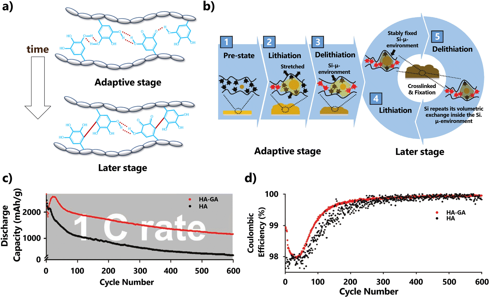 | ||
| Fig. 21 (a) Schematic illustration for chemical conversion from reversible H-bonds of gallols (red dashed line, adaptive stage, top) to irreversible covalent GA-to-GA cross-linking (later stage, bottom); (b) overall schematic description of the role of GA binders in the adaptability of the Si-μ-env; (c) discharge capacity of the electrodes utilising HA–GA (red) or HA binder alone (non-GA, black) for 600 cycles at a charge/discharge repeating rate of 1C. (d) Coulombic efficiency corresponding to the electrochemical analysis for the discharge capacity in (a): HA–GA for red and HA for black. Reproduced with adaptations from ref. 460 with permission from John Wiley and Sons; copyright © 2021 Wiley-VCH GmbH. | ||
3D binders based on epichlorohydrin (ECH) and HA obtained through chemical cross-linking reactions were proposed by Liang et al.,465 leading to superior mechanical strength. No surface degradation was observed on the electrode containing HA-ECH during lithiation/delithiation cycles, whereas that incorporating only the HA binder exhibited 2 μm-wide cracks. This system showed impressive electrochemical performance, notably in terms of outstanding cycling stability (Table 11). After 1000 cycles at a current of 0.2C, it maintained a capacity of 800.4 mA h g−1, with an average capacity decay rate per cycle of only 0.015%. More importantly, a higher mass loading of 3.0 mg cm−2 alongside a competing areal capacity of 12.4 mA h cm−2 was demonstrated (Table 11), and the device was still able to maintain a higher areal capacity than a commercial battery for 50 extra cycles at 0.1C.465
Recently, a self-assembled 3D network binder, obtained through the weaving of two anionic polysaccharides, namely HA and soluble soybean polysaccharide (SSPS), via supramolecular interactions, was designed by Li et al.222 The resulting binder provided adequate connection points both within itself and with SiNPs (Fig. 22). Both the polar amino groups of HA and the carbonyl groups of SSPS formed H-bonds with the hydroxyl groups present on the surface of the SiNPs, thereby increasing interfacial adhesion (Fig. 22). This 3D system avoided side reactions, enhancing the mechanical durability of the prepared electrode with a stable and efficient SEI. The proposed 3D network binder displayed favourable cycling performance with a capacity of 1407 mA h g−1 after 100 cycles at 4 A g−1 and high initial Coulombic efficiency reaching 92.67% (Table 11), demonstrating excellent reversibility and a stable SEI film. Likewise, the massive H-bond interactions formed between the binder and Si impart the electrode with self-healing ability.
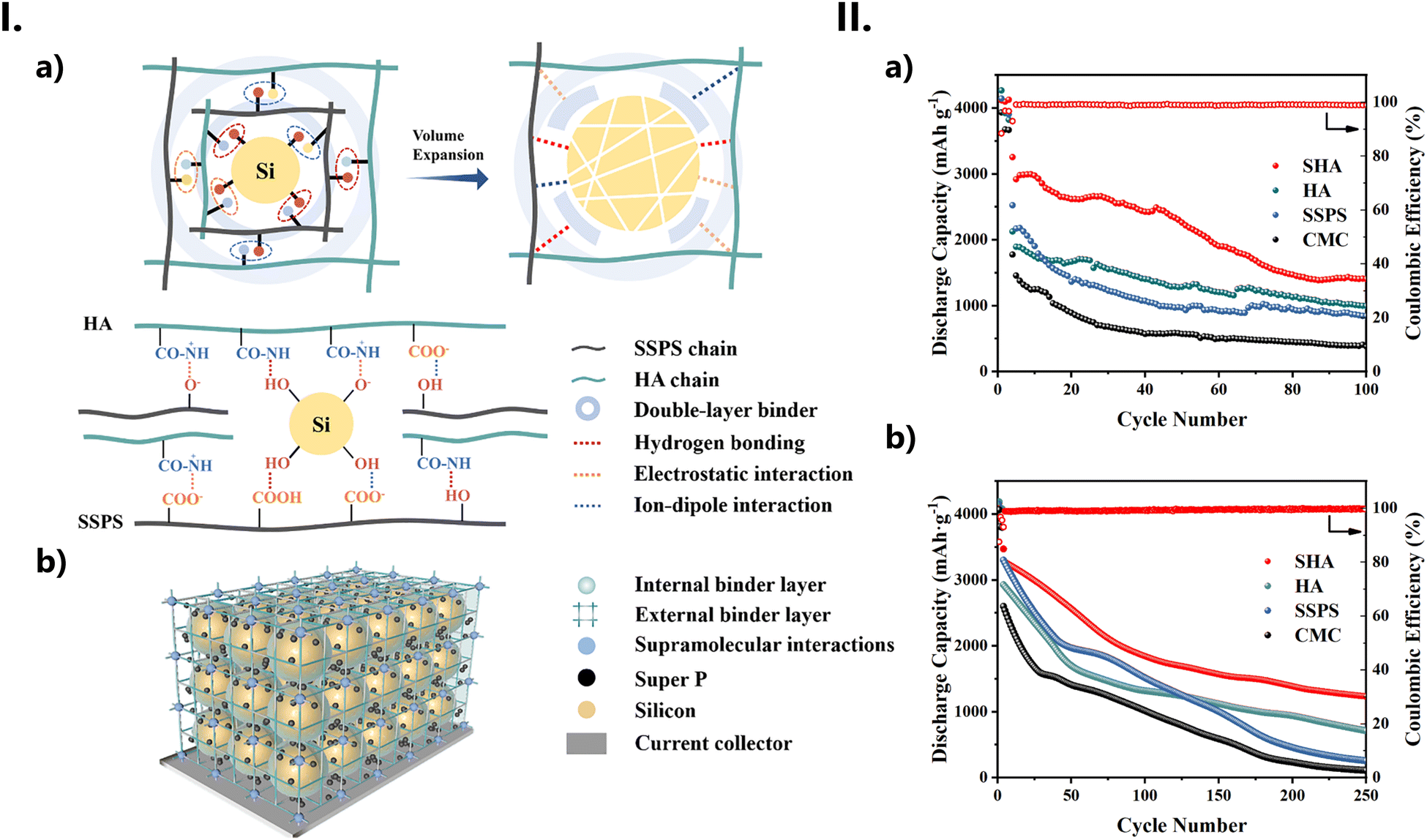 | ||
| Fig. 22 (I) (a) Schematic diagram of the double-layer binder network resisting against volume expansion and illustration of supramolecular interactions between HA and Si NPs. (b) 3D network of Si anodes with HA as binder. (II) Cycling performance of various binders at (a) 4 A g−1 and (b) 2 A g−1. Reproduced from ref. 222 with permission from Elsevier; copyright © 2018 Elsevier B.V. | ||
A composite binder containing HA and a fluorinated copolymer (IF, obtained from the co-polymerization of itaconic acid, acrylic acid, acrylamide and 2-(perfluorobutyl) ethyl methacrylate) (Fig. 23-I) was proposed by Shi et al.294 for Li-ion batteries. This binder takes advantage of both the extensive H-bond network and the multiple bonding between its polar groups. This approach not only addresses the volume expansion problem in Si anodes but also confers added mechanical stability while maintaining its elasticity and flexibility. The resulting electrode has significantly enhanced mechanical properties and good cycling performance, with a discharge specific capacity of 1461 mA h g−1 after 200 cycles at 1C or 2013 mA h g−1 after 150 cycles at 0.5C, and an ICE of 91.1% (Fig. 23-IIa and b). The prepared electrode was also found to have the same charge–discharge curves under different cycles, meaning that the Li-ion storage mechanisms are not affected by the binder (Fig. 23-IId). At high mass loadings, it maintained its capability to deliver a capacity of 535 mA h g−1 after 200 cycles at 0.125C (2.56 mg cm−2). Additionally, it exhibited a first-circuit discharge with a surface capacity of 31.08 mA h cm−2 for a loading of 12.03 mg cm−2 and a current density of 0.722 mA cm−2.
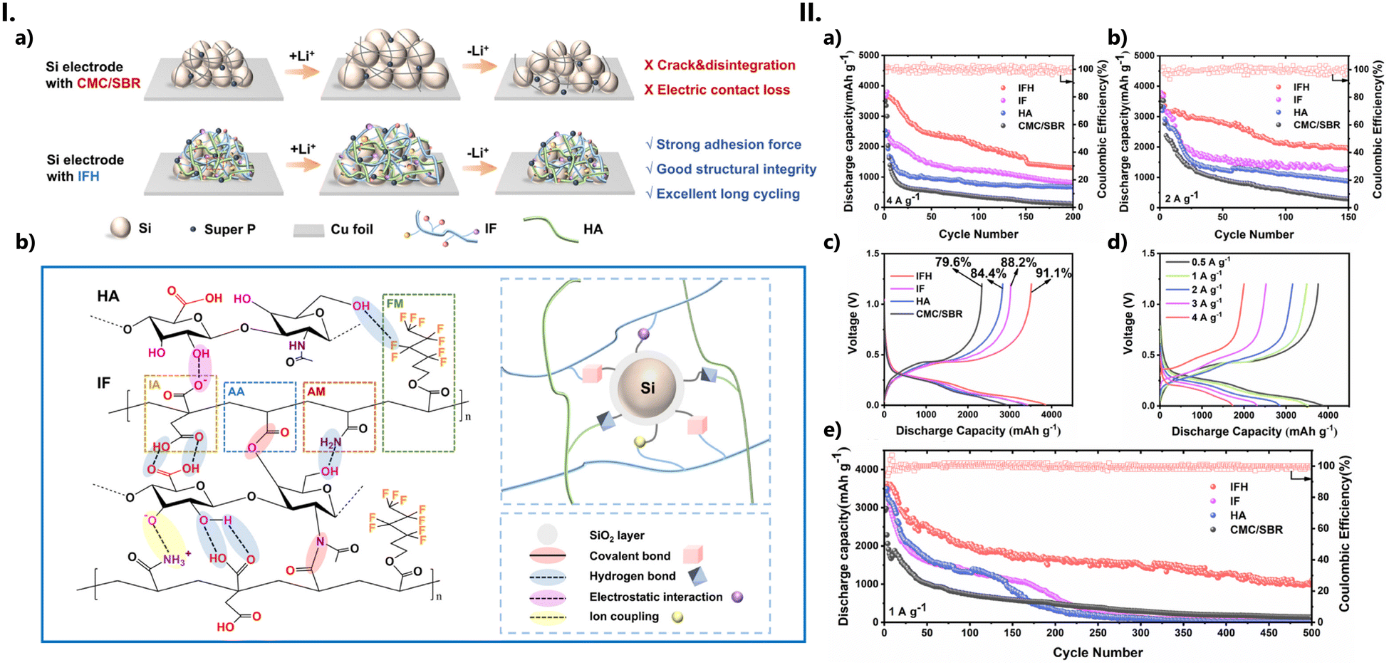 | ||
| Fig. 23 (I) (a) Schematic illustration of (de)lithiation processes of Si electrodes with the IFH binder. (b) 3D network structure of the IFH binder and the strong interaction with the Si particle. (II) Electrochemical performance of the Si electrodes with IFH, IF, HA, and CMC/SBR binders. Cycling performance and Coulombic efficiency at (a) 4 A g−1 (1C) and (b) 2 A g−1 (0.5C). (c) Initial Coulombic efficiency (ICE) at 1 A g−1 (0.25C); (d) rate capability of different Si electrodes at different rates; and (e) long-term cycling performance at 1 A g−1 (0.25C). Reproduced from ref. 294 with permission from Elsevier; copyright © 2023 Elsevier B.V. | ||
Binders for other types of electrodes. Although not as extensively used, GAGs have also been used in the preparation of binders for other types of electrodes.
Mu et al.468 blended a HA aqueous solution with an oily solution containing poly(acrylonitrile)-co-poly(ethylene glycol) bisazide (PCP), so as to attain a heterogenous polymer distribution. The resulting binder, consisting of submicroclusters rich in PCP, dispersed in a HA/PCP matrix, showed limited swelling rates (ca. 6%), improved mechanical properties and adhesion to an S-cathode, excellent lithium-polysulfide anchoring, and fast charge transport kinetics. These outcomes were attributed to the synergistic interactions between the HA and PCP polymers, their high affinity to both the electrolyte and electrode, and the extensive 3D H-bonded network formed by their various polar functional groups. The S-based cathode (S-loading of 0.5 mg cm−2 and a 5% wt. binder loading) in coin-type cells was able to sustain a discharge capacity of 504 mA h g−1 (2 C, 800th cycle) and a discharge retention of 74%. At high mass loadings (7.0 mg cm−2), the binder still retained an areal capacity of 6.2 mA h cm−2 (at 1C, 50th cycle).
CSA has recently been proposed as a binder for a hard carbon electrode in Na-ion batteries.469 On its own, the CSA binder was capable of improving the ICE by 82%. When combined with poly(ethylene oxide) (PEO), the resulting binder showed an ICE of 84%, with a reversible capacity in the first cycle of 343.9 mA h g−1 and long-term cycling stability (94% capacity retention, after 150 cycles at a current density of 50 mA g−1). At 60 °C, the aforementioned binder system still maintained a reversible capacity of 334 mA h g−1 after 90 cycles under the same current density. When assembled in a full cell, the binder also delivered a high energy density (181.05 W h kg−1 over 150 cycles). Overall, this new CSA/PEO binder outperformed conventional binders such as poly(vinylidene fluoride) and CMC, both in the 1st cycle and the full cell measurements (Fig. 24-I). Central to this performance is the presence of not only PEO but especially CSA, whose ionic groups (sulphate and amide anions) successfully interact with the ions present in the electrolyte—thus facilitating both the fast transport of Na+ cations as well as anion desolvation—as well as with the polar functional groups present on the surface of the hard carbon anode (Fig. 24-II). As a result, excessive consumption of the electrolyte is prevented, both by the passivation of the defects on the hard carbon surface as well as by a gentler electrolyte decomposition process (which in turn allowed the formation of a thinner, inorganic-rich SEI, Fig. 24-III) and a more sustainable electrode.
Self-healable batteries470 are developed by integrating components capable of establishing reversible bonds into a self-amending polymeric network. The healing process involves a typical supramolecular assembly where a variety of dynamic non-covalent bonds (such as H-bonding, metal coordination bonding or electrostatic cross-linking) work spontaneously to repair the damage sustained by these devices during operation. As such, self-healing batteries are expected to have longer, more stable lifecycles.
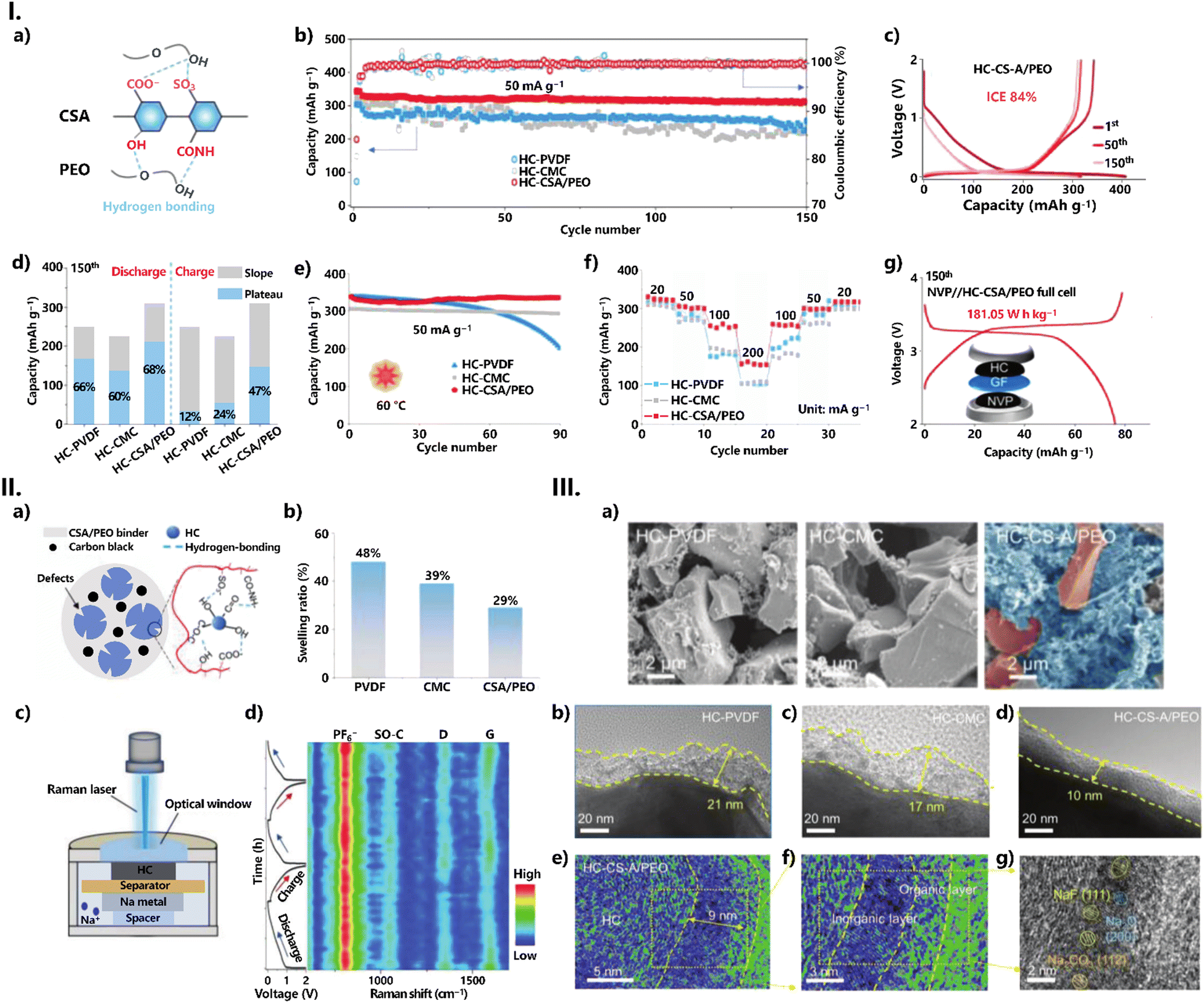 | ||
| Fig. 24 (I) Electrochemical performance of HC-PVDF, HC-CMC, and HC-CSA/PEO electrodes. (a) Chemical structure of the novel CSA/PEO binder; (b) cycle performance; (c) initial galvanostatic charge/discharge curves for HC-CSA/PEO, HC-PVDF and HC-CMC anodes; (d) normalized contribution ratio of sloping region capacity and plateau region capacity at the 150th cycle; (e) cycle performance at 60 °C; (f) rate performance; and (g) galvanostatic charge–discharge curves of the full cell with the HC anode using CSA/PEO as the binder. (II) Characterization of the proposed binder and SEI. (a) Schematic interactions of the electrode fabrication process using the CSA/PEO binder and HC anode; (b) swelling ratios of PVDF, CMC, and CSA/PEO films in EC/DMC solvent. (c) Illustration of an in situ Raman device; and (d) in situ Raman spectra and relative charge/discharge curves of HC-CSA/PEO. (III) SEI characterization of HC electrodes. (a) SEM images of HC-PVDF, HC-CMC, and HC-CSA/PEO electrodes. HRTEM images of (b) HC-PVDF; (c) HC-CMC; and (d) HC-CSA/PEO, initially discharged to 0.01 V. (e)–(g) Cryo-TEM of HC-CS-A/PEO, initially discharged to 0.01 V. Reproduced from ref. 469 with permission from John Wiley and Sons; copyright © 2023 Wiley-VCH GmbH. | ||
Even so, some challenges remain. For example, self-healing mechanisms should not introduce significant resistive losses or cause changes in the material's electrical properties. Maintaining the integrity of conductive pathways at the microstructural level is another critical consideration. In addition, energy harvesting and storage systems typically involve various components, such as electrodes, electrolytes, and separators. Thus, achieving effective integration between self-healing materials and these components is essential to ensure compatibility, preventing detrimental interactions, and optimising performance at the system level.
Tao et al.260 designed a flexible self-healing Na-ion battery using a HA/borax hydrogel (Fig. 25a). The authors combined this hydrogel with electroactive components NaTi2(PO4)3/C, and KNiIIFeIII(CN)6 to prepare both the anode and the cathode, intercalating those with an HA/borax/NaNO3 hydrogel (Fig. 25b). This led to an all-in-one configuration where various parts were integrated into the borate-cross-linked HA network, resulting in a battery that was flexible and could be freely twisted without breaking (Fig. 25d). After nine breaking/healing cycles, the battery was still displaying a specific discharge capacity of 54.7 mA h g−1 (Fig. 25g), and delivering a specific capacity of 48.3 mA h g−1 (88.3% retention rate) at the 200th cycle at 0.2 A g−1 (Fig. 25i). All in all, the battery offered excellent reliability, easy maintenance, and superior safety. The device consistently regained its structural integrity, microstructure, and both its electrochemical and mechanical properties even after undergoing nine cycles of breaking/healing, with an average healing efficiency of over 96%. The restoration of the energy-storage functions was achieved due to the dynamic borate ester bonding.
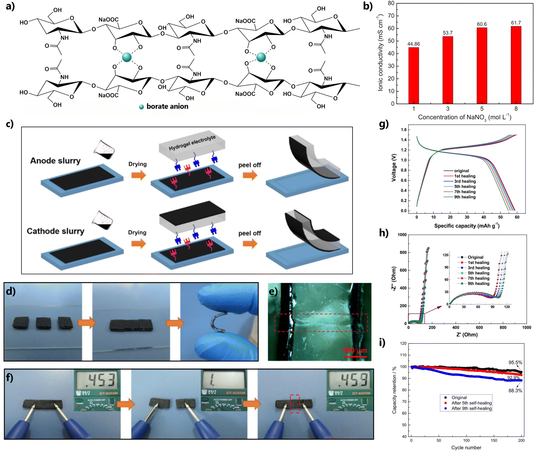 | ||
| Fig. 25 (a) Illustration of the formation of dynamic borate ester bonding between HA chains and (b) dependence of the conductivity of the hydrogel on the concentration of NaNO3 at room temperature. The content of HA in the hydrogel was 12.5% wt. (c) Fabrication of a self-healable Na-ion battery or capacitor: the anode and cathode films are first prepared through a casting process and then successively coated onto the opposite sides of the HA/borate/NaNO3 hydrogel electrolyte. (d) Self-healing of the Na-ion battery after cut-off under ambient conditions; (e) cross-sectional image of the healed region observed through optical microscopy; (f) resistance variation of the battery during the cut/healing process; (g) galvanic charge/discharge profiles of the battery at 0.2 A g−1; (h) Nyquist plots of the battery; and (i) cycling characteristics of the battery at 0.2 A g−1. Reproduced from ref. 260 with permission from the American Chemical Society, copyright © 2019. | ||
Aqueous Zn-ion batteries have emerged as a compelling and valuable alternative to Li-ion batteries, both for large-scale systems and portable electronics applications.473–475 Here, Zn metal serves as the anode, while Zn-intercalating materials act as the cathode, with a slightly acidic or even neutral Zn-containing solution functioning as the electrolyte. The attractiveness of Zn arises from a combination of practical issues, such as lower costs, higher abundance, and environmental friendliness than alkali metals. In addition, Zn also has a low redox potential (−0.76 V vs. standard hydrogen electrode), along with a substantial theoretical gravimetric and volumetric capacity of 820 mA h g−1 and 5855 mA h cm−3, respectively, as well as good compatibility with aqueous electrolytes.473,474,476 Even so, the use of these aqueous electrolytes can pose various challenges since the parasitic reactions due to water consumption will affect the local pH environment, inducing uncontrolled dendrite growth during plating/stripping and low Coulombic efficiency, which will ultimately lead to the deterioration of the Zn anode's stability.475,477
A typical strategy to efficiently improve the internal environment of batteries is to employ organic polymeric additives. These additives serve a dual purpose: they inhibit water activity by forming a cross-linked H-bond network and act as a shield to protect the Zn anode from induced deposition.477,478
Three independent papers reported, almost simultaneously, the use of HA as an additive to an aqueous solution of zinc sulfate (ZnSO4) with similar results.297–299 HA's ability to complex divalent anions has been known for a long time.471,472 Indeed, a small decrease in the ionic conductivity has even been reported due to both the formation of a Zn–HA complex in solution and, in a lesser proportion, to the slight increase in viscosity.299,472
Even so, in two of these studies,297,298 the conductivity measurements conducted denote a slight increase in conductivity upon the addition of small quantities of HA (Table 9). The previously reported negative effect on conductivity due to HA's sequestration of Zn2+ cations472 was indeed confirmed, but only for the more concentrated HA solutions (2.0 g L−1 by Qiu et al.;297 6% wt or higher by Li et al.299). Furthermore, a significant improvement in the mobility behaviour of the Zn2+ cations in the electrolyte was also observed, with higher Zn2+ transference numbers (0.62,297 and 0.73299 compared with 0.31 and 0.24 in the aqueous ZnSO4, respectively). The presence of HA also led to more uniform Zn deposition, with an enhanced Zn plating/stripping life. For their respective systems, Qiu et al.297 reported a lifespan of 800h at 5 mA cm−2 (5 mA h cm−2), while Li et al.,299 reported a lifespan of 1200h under the same conditions. For higher current density/capacity conditions, they observed whopping lifespans of 820 and 480h at 10 mA cm−2 (10 mA h cm−2) and 20 mA cm−2 (20 mA h cm−2), respectively, for Zn||Zn symmetrical batteries (Fig. 26).298 The results obtained for full Zn||manganese oxide (MnO2) batteries are also very similar; Qiu et al.297 found a 61.4% capacity retention after 1000 cycles at 1 A g−1, while Li et al.298 observed about 70% capacity retention after 1500 cycles at 0.616 A g−1. The Zn||LiMn2O4 battery exhibits 82% capacity retention after 1000 cycles at 3C.299
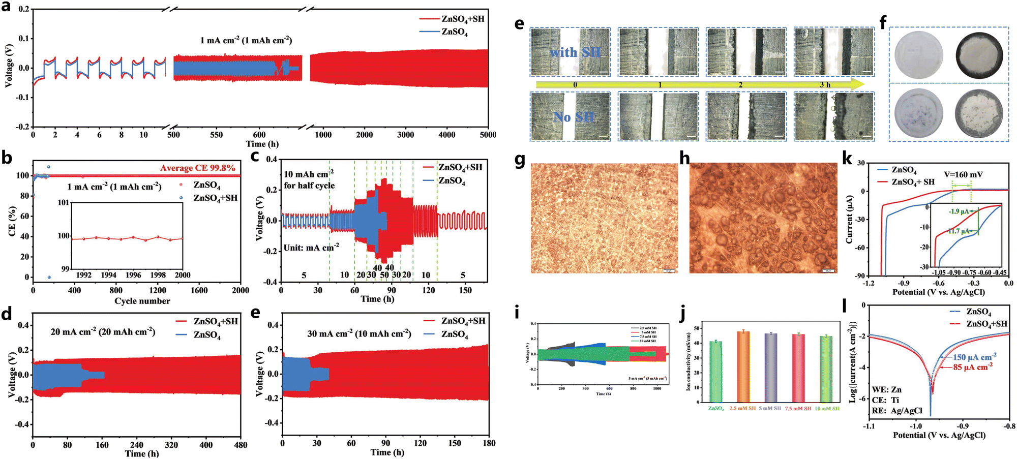 | ||
| Fig. 26 Electrochemical performance of the Zn anode. (a) Long-term cycling of Zn||Zn batteries and (b) Coulomb efficiency of Zn||Cu batteries tested in ZnSO4 + HA and ZnSO4 electrolytes at 1 mA cm−2 (1 mA h cm−2). (c) Rate performance of Zn||Zn batteries tested in ZnSO4 + HA and ZnSO4 electrolytes. (d) Long-term cycling of Zn||Zn batteries test in ZnSO4 + HA and ZnSO4 electrolytes at 20 mA cm−2 (20 mA h cm−2) and (e) 30 mA cm−2 (10 mA h cm−2). The morphology of Zn deposition and the hydrogen evolution reaction behaviour upon introducing HA. (e) In situ optical microscopic images of Zn plating in (up) ZnSO4 + HA electrolyte and (down) bare ZnSO4 electrolyte (scale bar: 200 μm). (f) Digital photographs of separators disassembled from Zn||Zn batteries using (up) ZnSO4 + HA and (down) ZnSO4 electrolyte. (g) and (h) Optical microscopy image (scale bar: 200 μm). (i) Comparison of long-term stability of Zn||Zn batteries with the addition of different HA concentrations under a current density and deposition capacity of 5 mA cm−2 and 5 mA h cm−2, respectively. (j) Ionic conductivity of ZnSO4 and ZnSO4 with different concentrations of HA. (k) Linear sweep voltammetry curves, and (l) Tafel curves of ZnSO4 + HA and ZnSO4 electrolytes. Reproduced from ref. 298 with permission from John Wiley and Sons; copyright © 2021 Wiley-VHC GmbH. | ||
8.2. (Super)capacitors
(Super)capacitors, alternatively referred to as electrochemical capacitors or ultracapacitors, are specialized energy storage devices designed to accumulate electrical energy via electrostatic double-layer capacitance or pseudocapacitance mechanisms. They offer several advantages over traditional batteries, including high-power density, fast charging and discharging rates, and an extended cycle life. These systems consist of two electrodes, as well as a gel electrolyte acting both as an electrolyte and separator (Fig. 20b). Upon the application of a voltage, positive ions migrate to the negative electrode, while negative ions move towards the positive electrode. This charge separation creates either an electrostatic double-layer or an electrochemical reaction, depending on the type of (super)capacitor (Fig. 20b).The wide range of applications of supercapacitors, from low-power electronics (such as portable or transient devices) to high-power applications, have made their development one of the most thriving topics in the field of energy storage systems.36,479 Supercapacitors can bridge the gap between the electrochemistry of batteries and conventional capacitors, presenting high power density, rapid electrochemical responsiveness, efficient charge–discharge processes, and extended lifecycles. Moreover, an ideal supercapacitor is expected to demonstrate outstanding mechanical properties, including strength, flexibility, elasticity, and stiffness, while also being environmentally friendly and cost-effective. Thus, in order to develop high-performance flexible supercapacitors, attention should be paid to the design of electrodes with high pseudocapacitive properties, suitable surface wettability, excellent chemical and thermal stability, and long-lifetime, while also taking into account the preparation of electrolytes with both superflexibility and superb ionic conductivity.479 Among the most widely explored electrode materials for the fabrication of flexible supercapacitors are (1) carbon-based materials, with high specific surface areas and exceptional mechanical strength and flexibility;480,481 and (2) conductive polymer-based composites482–484 which impart the electrodes with good conductivity, flexibility, a relatively low price, and ease of synthesis.
Polysaccharides have been proposed for (super)capacitor materials to play several roles, either as components in conductive composites or as templates in the preparation of highly-porous carbonaceous materials.36,485 In the present context, HA, but also CSA and HEP, have only been used in the preparation of conductive materials, often in combination with carbon nanomaterials (GO, MXene or CNTs) or conductive polymers such as PEDOT and PANI. Notwithstanding, there are a few exceptions. One of the first hydrogels proposed for supercapacitors was obtained through the combination of biomaterials DA and HA via a one-step carbodiimide conjugation. When electropolymerized, the resulting composite displayed high pseudocapacitance behaviour (up to 891 F g−1), an energy density up to 30.93 mW h g−1, and high discharge capacity (∼130 mA h g−1 at 10 A g−1), along with long-term stability.486
| GAG | Electrode | Areal capacitance (mF cm−2) | Specific capacitance (F g−1) | Energy density (mW h cm−2) | Power density (mW cm−2) | Cycling performance | Ref. |
|---|---|---|---|---|---|---|---|
| Capacity retention/current density or scan rate | |||||||
| ABA: 3-aminophenylboronic acid; CHT: chitosan; DA: dopamine; Gel: gelatin; GG: guar gum; GO: graphene oxide; PANI: poly(aniline); SWCNTs: single wall carbon nanotubes; *: values obtained after healing | |||||||
| HA | (SWCNT-HA)@PANI nanofibers | 446.03@1.3 mA cm−2 | 282.36 ± 90.93@25 mV s−1 | 88.27%@100 mV s−1 (3000 cycles) | 278 | ||
| HA | HA/SWCNT nanofibers | 51.35@6.5 mA cm−2 | 42.07 ± 10.98@ 25 mV s−1 | 94.39%@100 mV s−1 (3000 cycles) | 278 | ||
| HA | MXene/MWCNTs/HA fibers | 30.98 ± 3.02 | 82.5%@600 mA cm−2 (1000 cycles) | 285 | |||
| HA | HA/ABA/PANI hydrogel | 369@0.5 A g−1 | 85%@30 A g−1 (1000 cycles) | 487 | |||
| HA | (GG/PVA/HA)/(PEDOT:PSS) membrane | 18.75@0.5 mA cm−2 | 6.86 | 139.17 | 97.62%@0.3 mA cm−2 (500 cycles) | 307 | |
| HEP | HEP/PANI(= 0.25) | 732.18 ± 24.1@1 mA | 72.8%@1 mA (1000 cycles) | 371 | |||
| HEP | (PANI-HEP)/rGO nanofibers | 690.68@1 mA | 96 × 10−3 mW h kg−1@1 mA | 83.82%@1 mA (2000 cycles) | 412 | ||
| HA | HA/borax/NaNO3 hydrogel | 141.3 (139)* | 177.9 (148.3)*@1.0 A g−1 | (0.0556)*@1.0 A g−1 | (0.9224)*@1.0 A g−1 | 89.5%@1.0 A g−1 (1200 cycles)* | 260 |
| CSA | (Graphene/CSA-gelatin)/graphene | 2.74@100 mV s−1 | 3.1 | 70%@100 mV s−1 (100 cycles) | 488 | ||
In 2014 Sk et al.371 developed nanofibers based on PANI through a template-induced oxidative polymerization method, using HEP as a template. The functional groups on the surface of HEP served as morphology-directing sites (see Fig. 14 for a scheme of the underlying mechanism). The nanostructured electrode demonstrated pseudo-capacitance behaviour, good reversible stability, and fast response to oxidation/reduction. Its specific capacitance at a current density of 1 mA was measured to be 732.18 ± 24.1 F g−1, a six-fold improvement with respect to pure PANI, and it achieved a capacity retention of 72.8% (1000 cycles at 1 mA). When combined with rGO, the resulting (PANI-HEP)/rGO electrode exhibited a specific capacitance more or less at the same level (Table 12), but was capable of achieving a capacity retention of 83.82% after 2000 cycles at 1 mA.412 This result was a direct consequence of the presence of rGO, which helped to minimise the deformation arising from the volume variations observed in the nanofibers during the long-term charge/discharge cycles.412
As for the use of HA, Liu et al.487 used a boronic acid (3-aminophenylboronic acid, ABA) to cross-link PANI to HA. The resulting hydrogel, PANI/ABA/HA, was used in the preparation of a supercapacitor with a capacitance of 369 F g−1 (at a current density of 0.5 F g−1), which was able to retain 85% capacity after 1000 charge/discharge cycles at 30 A g−1. These results, which are superior to those obtained using the PANI/ABA hydrogel under the same experimental conditions (305 F g−1; 72% capacity retention), were directly linked to the presence of HA, which not only provided support and protection to the polymeric framework during expansion and contraction but also enhanced the interstitial conductivity due to its ion-solvation properties.
Zheng et al.278 assembled core–shell (SWCNT-HA)/PANI microfibers, where the HA-functionalized CNT core is covered with a uniform layer of PANI particles to form a highly conductive, flexible material. The specific capacitance of (SWCNT-HA)/PANI fibres was 282.36 ± 90.93 mF cm−2 (at a scan rate of 25 mV s−1), almost 7 times higher than the observed capacitance for the SWCNT-HA fibres (Table 12), whereas the electrode was able to retain 88.28% of its initial capacity after 3000 cycles at 100 mV s−1.
There has recently been some work reported on the preparation of GAG-based hydrogels (GAG = CSA and HA) which were incorporated into all-in-one (super)capacitor devices, permeating the whole device as both an electrolyte and a component of the electrode itself. These hydrogels, assembled by means of dynamic supramolecular interactions, can synergically combine the advantages of a strong water retention ability with high ion transport efficiency to form a material with superior electrochemical performance. The resulting devices have shown enhanced electrochemical performance due to reduced ion-diffusion resistance at the electrode/electrolyte interface and longer power supply times, while also maintaining the necessary mechanical robustness necessary for application as flexible (super)capacitors.260,307,488
CSA and gelatin were complexed through electrostatic interactions and then centrifugated in order to obtain a polyelectrolyte hydrogel. This hydrogel was shown to infiltrate the porous structure of a graphene electrode, and the resulting layered system was placed inside a Swagelok-type cell.488 The resulting supercapacitor achieved a capacitance of 3 F g−1 when cycled at 100 mV s−1 and maintained a capacitance retention close to 70% and a resistance value of 12 Ω cm2.
The above-mentioned HA/borate/NaNO3 hydrogel (Fig. 25a and b) was also used by Tao et al.260 in the assembly of a self-healable asymmetric capacitor device, in a similar way as depicted in Fig. 25c. Remarkably, this device exhibited an almost identical specific capacitance, both before and after self-healing (1–10 A g−1), showcasing a retention rate of 89.5% at the 1200th cycle even after undergoing nine cut/healing cycles, indicating robust restoration capabilities. Upon healing, the capacitor retained a specific capacitance of 56.7 F g−1 under a high load of 10 A g−1, representing approximately 38.2% of its value at 1.0 A g−1. Furthermore, the capacitor demonstrated the ability to power a light-emitting diode through successive cutting and self-healing processes.
Wang et al.307 designed a self-powered electronic stimulation wound dressing device with an integrated supercapacitor (Fig. 27-I). This device is composed of two layers: an upper layer with the supercapacitor to provide the necessary electric energy for electronic stimulation therapy, which is the purpose of the lower layer. HA permeates both layers, acting as a substrate material in order to improve electrochemical performance and prolong power supply time, while also acting as a therapeutic agent. The supercapacitor itself was a sandwiched all-gel device composed of a polyelectrolyte (obtained through the cross-linking of PVA, guar gum (GG) and HA by means of the freeze–thaw method) in between two polymeric gel membranes, acting as the anode and cathode (assembled from the cross-linking of the forementioned polyelectrolyte with PEDOT:PSS) and covered on both sides with carbon cloths (acting as current collectors) (Fig. 27-I).
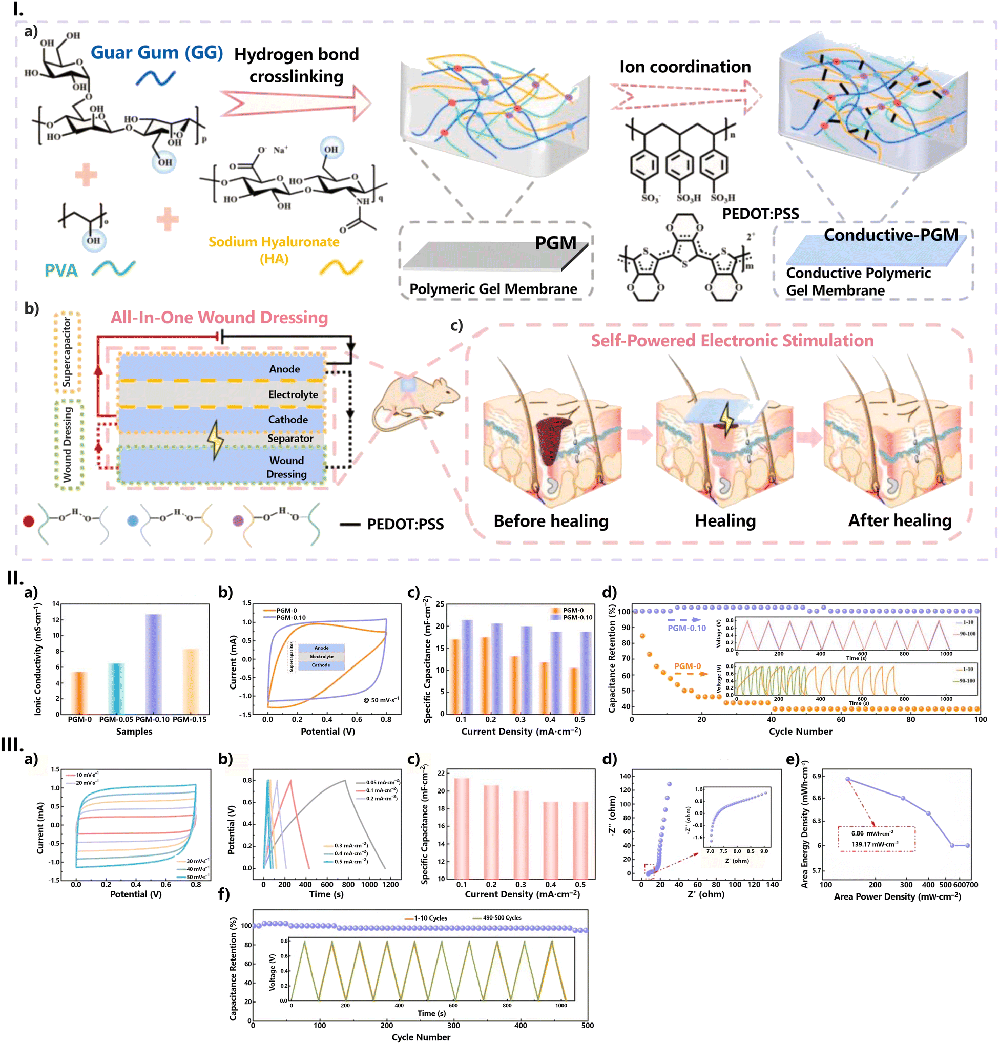 | ||
| Fig. 27 (I) (a) Preparation process of the polymeric gel membrane (PGM) and conductive polymeric gel membrane (conductive-PGM); (b) schematic diagram of the all-in-one wound dressing; and (c) schematic illustration of the healing process of self-powered electronic stimulation. (II) Electrochemical properties of the HA-containing polyelectrolytes PGM-x (x = 0, 0.05, 0.10 and 0.15, denotes the mass of HA, in mg, in the membrane): (a) ionic conductivity; (b) CV curves at 50 mV s−1; (c) plot of current density against the specific capacitance; and (d) cyclic stability. (III) The electrochemical performance of supercapacitors containing PGM-0.10 as a polymer electrolyte: (a) CV curves at different scan rates; (b) GCD curves at different current densities; (c) relation graph between current density and specific capacitance; (d) Nyquist diagram; (e) Ragone plot of energy density and power density; and (f) cyclic stability. Reproduced with adaptations from ref. 307 with permission from Elsevier; copyright © 2023 Elsevier B.V. | ||
The introduction of HA into the polyelectrolyte has been shown to have a noteworthy positive effect on the electrochemical properties of the host polymer. In addition to the significantly improved conductivity (from 5.5 to 12.7 mS cm−1 for the hydrogel without and with HA, respectively), the cyclic voltammograms also showed better symmetry, with a quasi-rectangular curve, along with a better capacitance retention than its non-HA counterpart, when tested in a capacitor cell for current densities between 0.1 and 0.5 mA cm−2 (Fig. 27-II). The all-gel supercapacitor device has been shown to have good electrochemical stability and ideal capacitive properties: good Coulombic efficiency; an energy density of 6.86 mW h cm−2 when the power density reaches 139.17 mW cm−2; and reversible charge/discharge behaviour for current densities in the range of 0.05 and 0.5 mA cm−2, with a capacity retention rate of 87.49% when the current density reached 0.5 mA cm−2. When evaluated at 0.3 mA cm−2, the prepared device was able to operate at full capacity for the first 100 cycles and still retained 97.62% capacity after 500 cycles, with the curves for the last 10 cycles still being highly consistent with those obtained for the first 10 cycles (Fig. 27-III).
8.3. Fuel cells
Fuel cells (Fig. 20d) are sophisticated devices designed to harness the chemical energy stored in fuels, such as hydrogen, and transform it into electrical energy utilizing an oxidizing agent, typically oxygen. Unlike other energy-conversion systems, such as combustion engines, fuel cells are better aligned with current energy concerns (e.g., renewable energy sources, modern energy carriers, energy security, higher conversion efficiencies, and easily scalable in power and/or capacity).490,491 Indeed, fuel cells have rapidly emerged as a key technology in the search for new, non-conventional sources of energy, the most promising of which is hydrogen.491,492These devices comprise four basic elements: two electrodes (an anode and a cathode), an ionic conductive electrolyte, and an external electrical circuit connecting the anode to the cathode. The device is supplied with fuel at the anode, where oxidation occurs. Subsequently, ions migrate from the anode to the cathode through the electrolyte medium (Fig. 20d). Simultaneously, electrons traverse from the anode to the cathode via an external circuit, generating direct-current electricity. At the cathode, facilitated by another catalyst, ions, electrons, and oxygen undergo reactions, resulting in the production of heat, water, and potentially other byproducts (Fig. 20d).
Among the various types of fuel cell types, polymer electrolyte fuel cells (PEFCs, also referred to as proton exchange membrane fuel cells (PEMFCs)), have garnered significant attention. Operating within the temperature range of −40 to 120 °C, these fuel cells are constructed with membranes (e.g., perfluorosulphonic acid-based membranes, such as Nafion®) capable of serving as an ionic (protonic) conductor while separating electrons and gaseous reactants from anode and cathode regions.493 In PEMFCs, the proton conductivity of polyelectrolytes is intimately related to their water uptake capacity. Nafion® membranes, while widely used, have several drawbacks, including high price, non-eco-friendliness, and low proton conductivity under anhydrous conditions, limited operation temperature (on account of the need of membrane humidification), and a relatively high gas permeability.494,495 In contrast, biopolymer membranes have been shown to be an interesting alternative to Nafion®.496–498
The most recent GAG-related system to be tested for use on a fuel cell was the CSA/CA system developed by our group, with conductivities reaching values as high as 37 mS cm−1, under a saturated atmosphere (Fig. 28).47 The system is quite simple, consisting of a combination of a Brønsted acid (CA) with a polysaccharide (CSA), acting as a base. However, while this association proved to be beneficial in terms of conductivity, as discussed previously (Section 7.1.), it was detrimental to the thermal stability of the material, with an onset decomposition temperature of 130 °C, against the 175 °C observed for the CSA precursor. This effect was attributed to the acidic hydrolysis caused by the presence of CA. Another issue that was found during the conductivity measurements was a decrease in conductivity at 50–60 °C (Fig. 28a), which was associated with the CSA gel–sol transition, causing the loss of mechanical properties.47 The proton conductivity of the membranes was highly humidity-dependent, with values ranging from 1.4 × 10⁻⁴ mS cm−1 for CA:CSA(82.3) at 30% RH to 37 mS cm−1 for CA:CSA(60.8) at 98% RH (Fig. 28c), confirming that these membranes are highly hydrophilic.
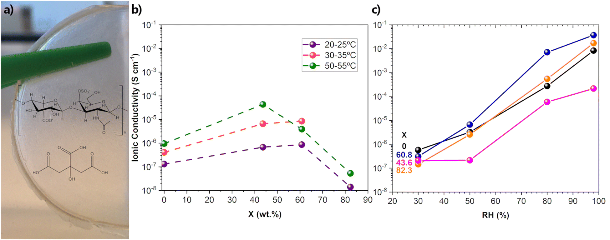 | ||
| Fig. 28 (a) Section of the prepared CSA/citric acid film, with the structures of both the GAG and the organic acid; (b) ionic conductivity isotherms obtained at RH < 30%; and (c) relative humidity dependence of the ionic conductivity under different RH at 25 °C for CSA and CA:CSA(X), with different w/w ratios (X = 0, 43.6, 60.8 and 82.3). Reproduced from ref. 47 with permission from Elsevier; copyright © 2019 Elsevier Ltd. | ||
A more successful pairing of an acid/base system containing a GAG was proposed by Yamada et al.218 In this case, the amphoteric heterocyclic amine imidazole was combined with previously protonated CSC (by means of a cation exchange column) to produce CSC/imidazole films. According to the authors, the gel–sol transition in CSC occurs at 100 °C,218 a temperature 50 °C higher than that observed for CSA.499 But, also importantly, the combination of CSC with imidazole did not negatively affect the decomposition temperature onset of the prepared films, highlighting the advantage of a Brønsted acid-free system. Indeed, infrared spectroscopy measurements of both the precursors and prepared films revealed a proton transfer from the polar groups of CSC to the N atoms in the imidazole molecule. Proton conductivity is, thus, thought to occur between a protonated imidazole entity and a neighbouring unprotonated one, which means that CSC/imidazole films with the highest conductivity should contain a very high amount of heterocyclic amine.218 In fact, the CSC/imidazole film with optimised conductive properties (1:9 molar ratio) exhibited a conductivity of 1.1 mS cm−1 at 130 °C under anhydrous conditions and an Ea value of 0.28 eV. Both values are on par with those of other anhydrous proton conducting systems combining imidazole with macromolecules.218,500
One of the most interesting systems proposed for fuel cells is also one of the first ones reported. Back in 2011, Zhao et al.219 developed a membrane for direct methanol fuel cells from the precursors CSA, hydroxyapatite HYA, and CHT (see Section 7.1. and Fig. 11).219 The hybrid membranes exhibited higher proton conductivity (up to 127%, see Section 7.1.) and lower permeability to methanol, which translated into a higher proton selectivity to methanol (about 1.8 times) when compared to the pure CHT membranes.
8.4. Solar cells
In 2012, Peng et al.501 proposed a system consisting of PPy nanorod networks/carbon NPs as an efficient counter electrode for dye-sensitized solar cells (DSSCs). The PPy nanorods were obtained using both HEP and MB as morphology directing agents (Fig. 14). DSSCs have become quite interesting photovoltaic (PV) devices by contraposing their lower power efficiencies and stability (when compared to other PV devices) with advantages like low-cost, sustainable manufacturing process, low maintenance requirements, and their ability to operate under less-than-optimal conditions, including indoors. Typically, a DSSC consists of a dye-sensitized semiconductor oxide photoelectrode (such as titania, TiO2), a liquid electrolyte containing the I−/I3− redox couple, and a platinum thin film as the counter-electrode (Fig. 20e).502–504 The high conductivity of the PPy nanorod network (on the order of 4 × 10⁴ mS cm−1, Table 10) obtained by Peng et al.501 already more than qualifies the system to serve as an alternative to the usual Pt counter electrode. However, the electrolytic performance was further improved upon the addition of carbon NPs. In fact, the addition of 10% wt. carbon NPs led to a reduction in the charge transport resistance and, accordingly, better catalytic performance for the reduction of triiodide (I3−). The resulting DSSC achieved a power conversion efficiency of 7.2% (Fig. 29). | ||
| Fig. 29 (I) (a) Schematic diagram of triiodide reduction on the pristine PPy nanorod networks and PPy/C composite counter electrodes, respectively. (b) Cyclic voltammograms of pristine PPy, carbon, PPy/C(10%), Pt electrodes at a scan rate of 50 mV s−1 in a 10 mM LiI, 1 mM I2 acetonitrile solution containing 0.1 M LiClO4 as the supporting electrolyte. (II) Nyquist plots of symmetrical cells consisting of (a) two identical pristine PPy, carbon, Pt, and PPy/C(5%); (b) PPy/C(10%), PPy/C(15%), and Pt electrodes; and (c) the equivalent circuit for the impedance spectrum. (III) Current density–voltage (J–V) curves of (a) the DSSC based on pristine PPy, carbon, PPy/C(5, 10, and 15%) and Pt counter electrodes under AM 1.5 (100 mW cm−2); and (b) of the DSSCs based on such PPy/C(10%) films with different thicknesses as counter electrodes under AM 1.5 (100 mW cm−2). Reproduced from ref. 501 with permission from The American Chemical Society; Copyright © 2012. | ||
More recently, the use of HEP505,506 and HA507,508 in organic–inorganic hybrid perovskite solar cells has been reported (Table 13). Perovskite solar cells have rapidly become one of the most intense research areas in PVs due to their fast-growing power conversion efficiency, which is currently certifiably higher than 25%.509–512 These systems present a series of desirable features which make them attractive, among which are an optical band gap of around 1.5 eV, an inexpensive and straightforward manufacturing process, extended diffusion lengths and minority carrier lifetimes, showcasing a broad absorption range spanning from the visible to the near-infrared (NIR) spectral regions (800 nm), a high dielectric constant, a fast charge separation process, a long transport distance of electrons and holes, and long charge carrier diffusion length (∼100 μm).509–511
| GAG | Modified layer | Structure | VOC (V) | JSC (mA cm−2) | PCE (%) | FF (%) | Stability | Ref. | |
|---|---|---|---|---|---|---|---|---|---|
| BCP: bathocuproine; FTO: fluorine doped tin oxide; ITO: indium tin oxide; PC61BM: phenyl-C61-butyric acid methyl ester; PEN: poly(ethylene 2,6-naphthalate); PET: poly(ethylene terephthalate); PTAA: poly(triarylamine); spiro-OMeTAD: 2,2′,7,7′-tetrakis(N,N′-di-p-methoxyphenylamine)-9,9′-spirobifluorene. MPP: maximum power point. | |||||||||
| HEP (Na+ salt) | TiO2 | FTO/TiO2/HS/MAPbI3/spiro-MeOTAD/Au | w | 1.114 | 23.34 | 20.1 | 77.31 | 85% after 70-day air-storage | 505 |
| w/o | 1.091 | 21.29 | 17.20 | 74.07 | 20% after 70-day air-storage | ||||
| HEP (K+ salt) | SnO2 | ITO/SnO2/perovskite/spiro-MeOTAD/Au | w | 1.162 | 25.00 | 23.03 | 79.2 | 97% after 1000 h operation at MPP under 1 sun illumination | 506 |
| w/o | 1.123 | 24.22 | 20.77 | 76.3 | 77% after 642 h operation at MPP under 1 sun illumination | ||||
| HEP (K+ salt) | SnO2 | ITO/PET/SnO2/perovskite/spiro-MeOTAD/Au | w | 1.090 | 23.74 | 19.47 | 75.24 | 93% after 500 bending cycles | 506 |
| w/o | 1.050 | 23.38 | 17.57 | 71.57 | 24% after 500 bending cycles | ||||
| HA (Na+ salt) | Perosvkite | PEN/ITO/PTAA/perovskite/PC61BM/BCP/Ag | w | 1.10 | 22.41 | 20.01 | 81 | 90% of after 6000 bending cycles at a 2 mm curvature radius; 60% after 200 h under a humidity (>70%) air environment; 83% of after 2500 h in N2 atmosphere at room temperature | 507 |
| w/o | 1.03 | 20.98 | 17.32 | 80 | 61% of after 6000 bending cycles at a 2 mm curvature radius; 32% after 200 h under a humidity (>70%) air environment; 44% of after 2500 h in N2 atmosphere at room temperature | ||||
| HA (Na+ salt) | Perovskite | ITO/PTAA/perovskite/C60/BCP/Ag | w | 1.10 | 23.42 | 20.86 | 81.2 | 70% after 1000 h under dark and ambient atmosphere | 508 |
| w/o | 1.04 | 22.89 | 19.16 | 80.7 | 32% after 1000 h under dark and ambient atmosphere | ||||
However, the efficiency of these cells is a reflection of the entire system. This means that each layer in the device is required to harmoniously work with each other, and that energy level alignment at the interfaces should be considered. Due to the nature of the growth process of the bulk films, defects are bound to arise, both at the films and the interfaces, which will affect the performance of perovskite solar cells. External factors such as H2O, heat, oxygen, and light contribute to the solar cell's poor stability.511,513 A common strategy to alleviate these shortcomings is the introduction of functional materials capable of stabilising the perovskite films and/or strengthening interface contact and facilitating charge transport.511,514
Overall, both HEP505,506 and HA507,508 were added to perovskites in an effort to improve the quality of the films and the interface energetics (Table 13). In both cases, this was achieved through the coordination of the Pb2+ cations with their carboxylate and sulfate (in HEP only) functional groups. Additionally, the alkali counter-cations naturally present in the polysaccharide materials also interacted with the I− anions present in the organic/inorganic films, further contributing to the stability of the perovskite films.
In 2018, You et al.505 created a methylammonium lead triiodide (MAPbI3) perovskite solar cell with increased stability and enhanced trap passivation. This was achieved by incorporating HEP as an interfacial layer to secure the perovskite absorber and TiO2 cathode. The HEP-modified TiO2 cathode fostered a uniform morphology with enhanced hydrophilic wettability, thereby enhancing the crystallization of MAPbI3 bulk films and diminishing trap density.505 The introduction of HEP thus resulted in a solar cell with an improved PCE of 20.1% compared to the control device (Table 13), with suppressed hysteresis, and Shockley–Read–Hall recombination. Moreover, the HEP interface modification demonstrated a significant delay in device degradation, with 85% of the initial efficiency retained even after 70 days of air storage, showcasing pronounced resilience against deterioration.
In a follow-up work, HEP potassium was employed to create an interfacial layer between the electron transport layer (tin oxide, SnO2) and the perovskite, Cs0.05FA0.85MA0.10Pb(I0.97Br0.03)3 (FA = formamidinium; MA = methylammonium).506 The improvement of interface interactions resulted from the synergetic interaction of HEP with both layers, not only enabling more uniform crystal nucleation, and hence improved growth of the perovskite crystals, but also attenuating the interaction between the perovskite and the SnO2 crystals while facilitating uniform dispersion. The average efficiency for this HEP-modified solar cell was determined to be 23.03 and 19.47% for rigid and flexible substrates, respectively, an improvement from the 20.77 and 17.57% observed for the respective HEP-free devices (Table 13). The flexible devices also presented enhanced mechanical stability, with the HEP-modified solar cell maintaining 93% of the initial efficiency after 500 bending cycles, while the control device showed a continuous decrease in efficiency, ending the stress cycle with a performance of only 24%.
HA has also been used as an additive for the construction of a flexible perovskite solar cell (Table 13).507 However, unlike previous HEP experiments, HA was added to the perovskite precursor solution in order to build a HA/perovskite network. The resulting cell displayed enhanced photovoltaic properties with an efficiency of 20.01%, a gain of 2.70% compared to the control device, as well as maintaining 90% of the initial efficiency after 6000 bending cycles (Table 13). In fact, when compared with the control perovskite film, the elongation at break and the fracture strength of the HA-based perovskite film showed a robust increase from 1.58% to 5.02% and from 23.13 to 55.25 MPa, respectively. This remarkable mechanical stability is justified by the strong interaction observed between the HA and the perovskite grains, which led to the grains becoming perfectly embedded in the polysaccharide network, thus allowing the dissipation of system energy while under tensile stress. Moreover, the intertwining of perovskite grains in the HA network was shown to not affect the perovskite crystal structure but rather increase the crystallinity of the perovskite film, resulting in a material with enhanced toughness and strength.
8.5. Electrochromic devices
Electrochromic devices (ECDs) (Fig. 20e) undergo alterations in their optical characteristics when subjected to an externally applied voltage or current. They serve the purpose of actively regulating light and heat transmission across windows and glazing. The efficacy of an ECD hinges on several factors, including its switching time between transparent and coloured states and vice versa, durability across numerous switching cycles without noticeable degradation, coloration efficiency, requisite applied voltage for switching, electro-optical properties (such as the degree of transmittance and absorbance reduction across specific wavelengths or bands of wavelengths), cycling stability, and the breakdown potentials of the constituent EC materials.The exploration of GAG-related materials for ECDs is still in its early stages, with only a couple reports on HEP-PPy films.361,515
The electropolymerization of HEP and PPy onto a fluorine-doped tin oxide (FTO)-coated glass surface afforded a compact and homogenous HEP-PPy layer with a globular form (50–80 nm in dimensions). The electrochromic features of the prepared PPY-HEP films were analysed under different solvents (Table 14). The highest switching speed (1s) and the maximum transmittance contrast, ΔT%, were obtained for aqueous solutions. In addition, the presence of HEP was also responsible for a boost in coloration efficiency (173 cm2 C−1 in aqueous solution), and a significant increase in the electro-optical stability of PPy: the optical contrast shifted only from 48 to 42%, after 100 steps.
| Dopant | Solvent (ε) | ΔTa (%) | ΔTb (%) | Switching time (s) |
|---|---|---|---|---|
ε-Dielectric constant; ΔT = Tneut − Tox; a![[thin space (1/6-em)]](https://www.rsc.org/images/entities/i_char_2009.gif) 1st and b50th switching steps; PC-propylene carbonate; and MeCN-acetonitrile. 1st and b50th switching steps; PC-propylene carbonate; and MeCN-acetonitrile. |
||||
| HEP | Water (78.4) | 48.0 | 1.0 | |
| PC (69.0) | 36.0 | 25.0 | 1.5 | |
| MeCN (37.5) | 27.0 | 7.0 | 2.3 | |
This effectiveness of HEP in the enhancement of electro-optical properties of PPy films did not seem to be maintained when MB was added to the system. In fact, the prepared (PPy-MB)/HEP films exhibited response times more than twice as long and smaller optical contrast compared to the previously discussed system.515
8.6. Conductive inks
Conductive inks are thermoplastic, viscous pastes that are capable of conducting electricity due to the presence of conductive materials. These materials are used to form conductive elements in electronic applications, making them profoundly used in all kinds of flexible, wearable, or printed electronic applications. Such systems are the result of a complex formulation where the conductive material employed is of prime importance.More specifically, conductive inks consist of volatile solutions composed of a conductive or semi-conductive micro/nanoscale material, such as metallic nanorods, CNTs, graphene, conductive polymer NPs, or a mixture of these materials. For ink formulation, different parameters need to be optimised. The accurate selection of precursors, solvents, additives, surfactants, and binders needs to be tailored for the deposition and processing technique with the aim of enhancing the printability of functional inks.516 Concerning ink design, several aspects need to be considered, namely, mitigating the coffee-ring effect, enhancing surface wetting while minimizing ink spreading, ensuring long-term ink stability, and ensuring compatibility with the chosen printing technique.517,518
In order to properly select the printing technique, it is essential to take into account both the ink's viscosity and the surface roughness of the deposited film. Generally, low-viscosity inks are compatible with inkjet printing, gravure printing, blade coating, slot-die coating, or spray coating methods. Conversely, high-viscosity inks are more suitable for screen printing, stencil printing, or micro-dispensing printing processes.517
Several of the materials reported here are suitable for bioink applications (Tables 9 and 10). When a bioink is sought, the goal is to obtain a material capable of encapsulating living cells to create tissue constructs. This implies that the prepared hydrogel should not only be biocompatible (and if necessary, biodegradable), but also possess the necessary mechanical, rheological, and chemical characteristics that will enable it to properly interact with the surrounding tissues and ensure the correct functionality of the bioprinted materials.519 While the context of bioinks is outside of the scope of this review, the idea that these conductive hydrogels can be used to fabricate 3D constructs is valuable to areas beyond biomedical applications, such as flexible electronics.520,521
Out of the handful of studies that we have identified concerning GAG-related materials in the context of conductive inks (Tables 9 and 10), a significant portion involved the use of nanostructures, such as metallic NPs,289,292 GeP nanosheets302 and carbon-containing nanostructures either in the form of CNTs283 or MXenes.256 The combination of nanomaterials with hydrogels has proven to be extremely advantageous by not only improving the shear-thinning characteristics of the hydrogel but also providing structural stability as well as higher mechanical strength, among other functionalities.
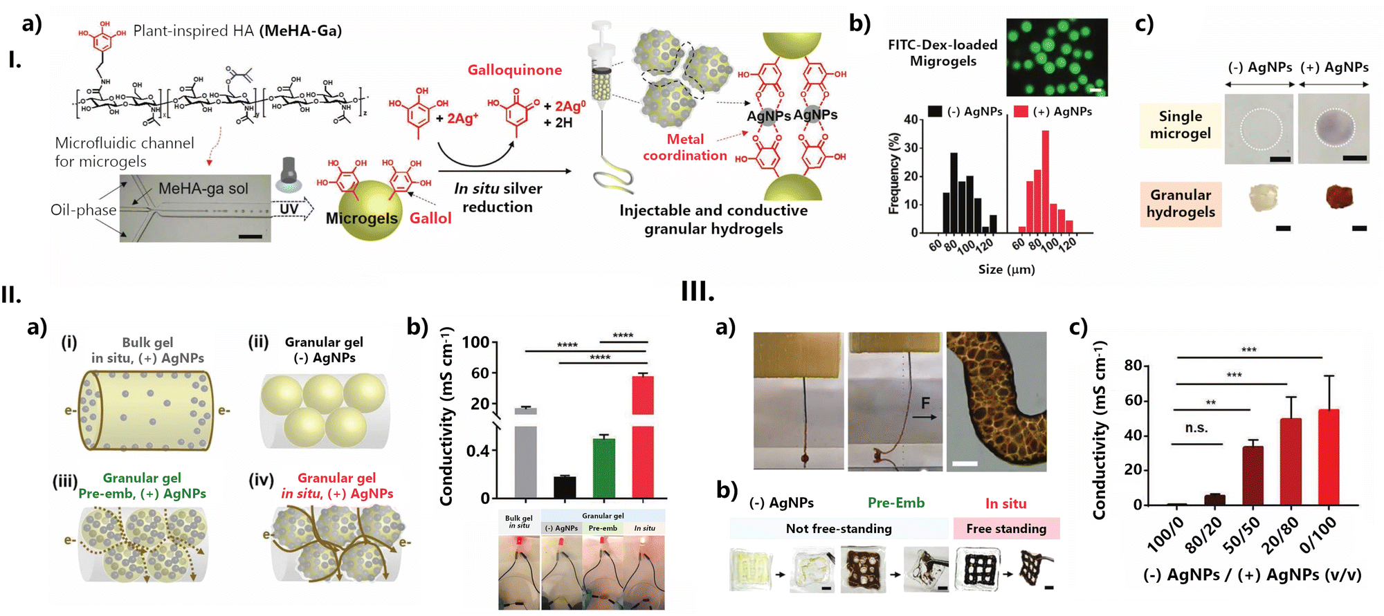 | ||
| Fig. 30 (I) Fabrication of conductive granular hydrogels and their characterization. (a) Schematic of the preparation of conductive granular hydrogels using a microfluidic device to form microgels (formed with methacrylated and gallol-modified HA, MeHA-Ga) through a water-in-oil emulsion, in situ metal reduction by GA moieties, and then jamming through vacuum filtration. (b) Size distribution of microgels without ((−)AgNPs, black) or with ((+)AgNPs, red) AgNPs. The fluorescent image shows the microgels with encapsulated FITC-dextran for visualisation. Scale bar: 100 μm. (c) Optical images of single microgels (top) or granular hydrogels (bottom) either without ((−)AgNPs) or with ((+)AgNPs) in situ metal reduction. The colour change is due to the introduction of silver nanoparticles. A scale bar of 50 μm for top images and 3 mm for bottom ones. (II) Conductivity of granular hydrogels. (a) Schematic of hydrogel structures, including: (i) bulk hydrogels with AgNPs through the in situ process (“in situ”), (ii) granular hydrogels without AgNPs, (iii) granular hydrogels with AgNPs pre-embedded during microgel fabrication (“pre-emb”), or (iv) granular hydrogels with AgNPs through the in situ process. The brown line describes the proposed electron (e−) transfer passing through each hydrogel, including a solid line for continuous flow and a dashed line for discontinuous flow. (b) Electrical conductivity in various hydrogels. One-way ANOVA, Dunnett's test for multiple comparisons to “in situ” microgels, ****p < 0.0001. (c) LED-emitting tests in an electrical circuit serially connected with various hydrogels, showing the greatest light intensity for granular hydrogels with microgels treated with the “in situ” process. (III) 3D printing of conductive hydrogels. (a) Images of the 3D printing process of the conductive granular hydrogels and the morphology of the printed filament. The black arrow indicates a physical force (F) applied to the filament with needle translation during printing, showing the filament's self-support. (b) Printability of the granular hydrogels fabricated from microgels without AgNPs (“(−)AgNPs”) or with pre-embedded (“pre-Emb”) or in situ synthesised (“in situ”) AgNPs on the polymeric film and their free-standing stability when removed with forceps. (c) Conductivity of extruded filaments as a function of volumetric mixing ratio v/v of the “(−)AgNPs” or “in situ, (+)AgNPs” microgels. One-way ANOVA, Dunnett's test for multiple comparisons to “100/0” filament, n.s. for not significant, **p < 0.01, ***p < 0.001. Scale bars: 100 μm for (a) and 3 mm for (b). Reproduced with adaptations from ref. 292; copyright © 2019 The Author(s). Published by Wiley-VCH Verlag GmbH & Co. KGaA, Weinheim. This work is licensed under a Creative Commons Attribution 4.0 CC-BY International License. | ||
Recently, KIyotake et al.289 have developed a bioink based on citrate-capped gold nanorods (citrate-AuNRs) integrated into a bioprintable hydrogel formulation consisting of pentenoate-functionalized HA (PHA) and pentenoate-functionalized gelatin (PGel). In this system, the AuNR hydrogel precursors demonstrated higher printed shape fidelity, with 2.3 times larger pore areas than the PHA/PGel without the Au NRs. In addition, the structural integrity of taller printed scaffolds, particularly 8-layer grids fabricated using PHA/PGel in conjunction with the Au NR precursor, demonstrated enhanced building potential. The conductivity of the prepared PHA/PGel/AuNR hydrogels increased proportionally with increasing AuNR content up to 0.8 mg mL−1.
An injectable hydrogel was formulated by integrating conductive and biodegradable germanium phosphide (GeP) nanosheets into an adhesive HA-graft-DA hydrogel matrix,302 using horseradish peroxidase (HRP)/H2O2 as an initiator system. To enhance the biostability and biocompatibility of the GeP nanosheets, polydopamine (PDA) was coated onto the surface of GeP nanosheets, resulting in the nanocomposite GeP@PDA. The cross-linked HA–DA/GeP@PDA biohybrid hydrogel (Fig. 31) was promoted via oxidative coupling of the catechol groups. Different mass ratios of HA–DA/GeP@PDA were synthesised (ranging from 0 to 0.25 and 0.5 wt%).
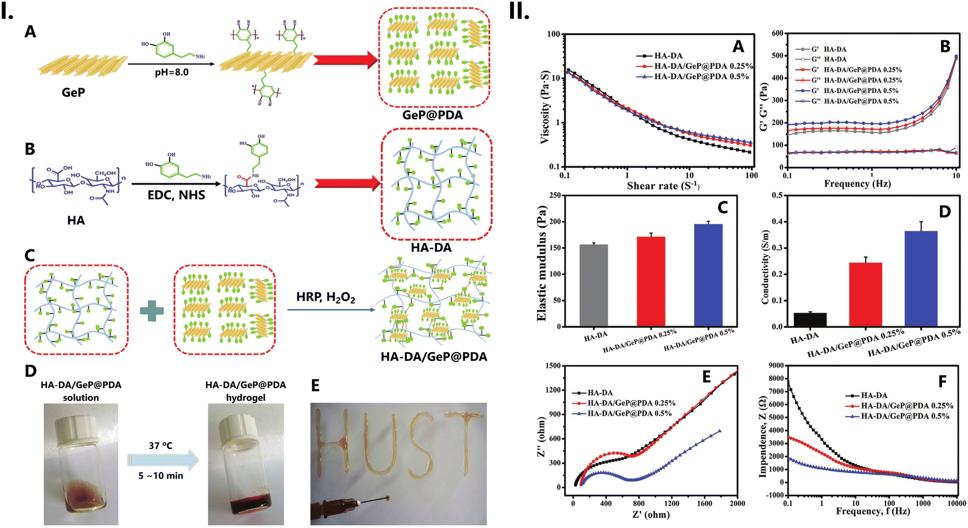 | ||
| Fig. 31 (I) Preparation scheme of (A) GeP@PDA nanosheets, (B) HA–DA polymers, and (C) HA–DA/GeP@PDA conductive hydrogels. (D) Photograph of the HA–DA/GeP@PDA prepolymer and hydrogel, and (E) photograph of the HA–DA/GeP@PDA hydrogel prepared through an injectable process with a 26-gauge needle. (II) Characterization of HA–DA and HA–DA/GeP@PDA injectable hydrogels. (A) Viscosity of HA–DA and HA–DA/GeP@PDA hydrogels with the shear rate ranging from 0.1 to 100 s−1. (B) Storage modulus (G′) and loss modulus (G′′) of HA–DA and HA–DA/GeP@PDA hydrogels. (C) The elastic modulus of the three types of hydrogels under compression in a fully swollen state. (D) The conductivity of the HA–DA and HA–DA/GeP@PDA hydrogels. (E) Nyquist curves and (F) impedance spectra of HA–DA and HA–DA/GeP@PDA hydrogels. Reproduced with adaptations from ref. 302 with permission from John Wiley and Sons; copyright © 2023 Wiley-VCH Verlag GmbH. | ||
The uniformly dispersed GeP@PDA nanosheets were interwoven in the HA–DA hydrogel matrix, allowing the establishment of new electronic pathways. Overall, an enhancement in the biohybrid hydrogel's electrical conductivity was observed, with higher mass rations of GeP@PDA nanosheets showing the greater improvements. The highest conductivity (3.65 mS cm−1) was detected for HA–DA/GeP@PDA (0.5%).
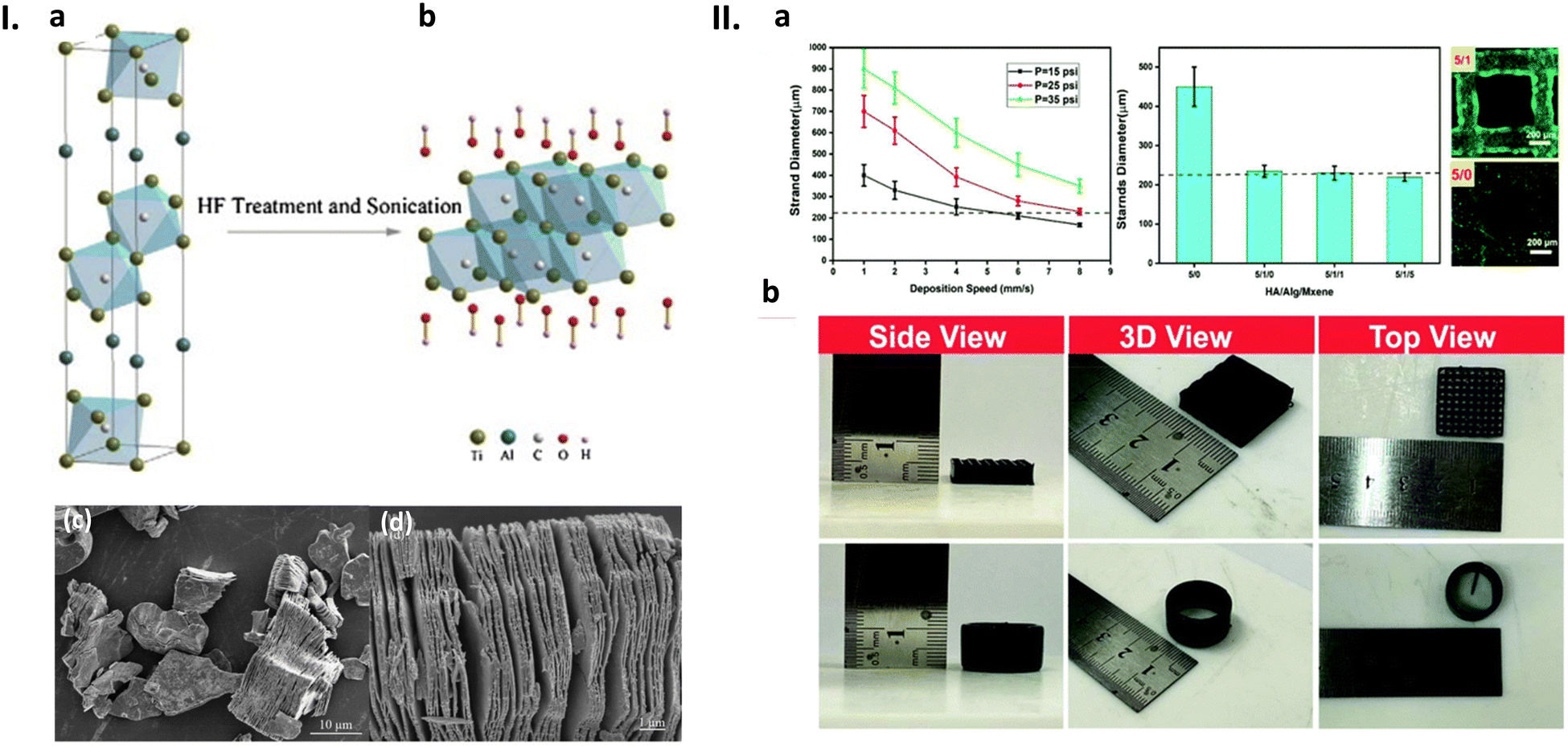 | ||
| Fig. 32 (I) Preparation and structure of Ti3C2 MXene. (a) Chemical structure of Ti3AlC2; (b) chemical structure of Ti3C2, with OH termination (Ti3C2 was made from Ti3AlC2 by HF etching and sonication); (c) and (d) SEM images of exfoliated Ti3AlC2 by 49% HF at 60 °C for 24 h. In (c), a low magnification is presented to show all grains are exfoliated, and in (d) a high magnification is used to show a fully exfoliated grain. Reproduced from ref. 529 with permission from Elsevier; copyright © 2015 Elsevier B.V. (II) Evaluation of the printability of MXene nanocomposite ink. (a) Finding the optimised operating parameters for extrusion-based 3D printing. (b) Pictures of 3D-printed structures fabricated using the MXene nanocomposite ink containing 1 mg mL−1 Ti3C2 MXene nanosheets. Reproduced from ref. 256 with permission from The Royal Chemical Society; copyright © 2020. | ||
As for CNT-based inks, Shin et al.282,283 combined DNA with a HA-coated SWCNTs suspension to produce an ink that was used in the printing of 3D constructs (Fig. 33). The resulting material had a viscosity of 2.05 Pa s at a 50 s−1 shear rate, making it more suitable for extrusion-based 3D printing. This attractive viscosity value was the result of the combination of both a high content of biomaterials and a high number of CNTs.283 When ejected from a 3D printer, the ink solution coagulated instantly, producing microfibers with a diameter of approximately 80 μm and a porous surface. These nanofibers possessed superior mechanical features, both in terms of toughness and flexibility, which enabled fibre retraction into the printer's nozzle system and eased their printability. The conductivity was evaluated to be 128 ± 15 mS cm−1, a value of the same order of magnitude as those found for other GAG/NT composites (Fig. 33).
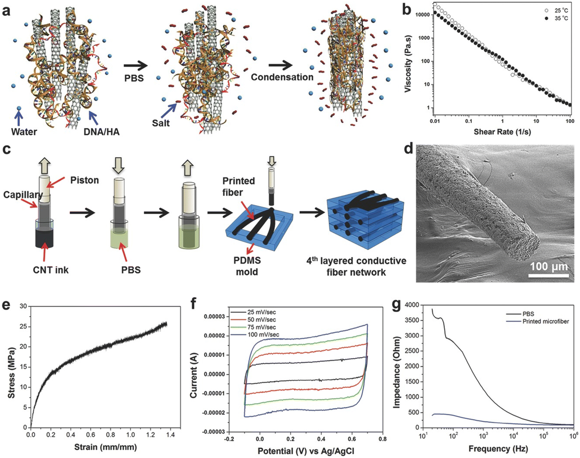 | ||
| Fig. 33 Ink generation and deposition process for printing 3D electrically conductive constructs. (a) Schematic diagram of the coagulation process of DNA/HA-coated SWCNT inks. (b) Viscosity dependence as a function of shear rate for DNA/HA-coated SWCNT inks. (c) Schematic diagram of the 3D printing process. (d) SEM image of the porous printed fibres. (e) Strain–stress curve of swollen printed fibers (elastic modulus: 63.56 ± 21.79 MPa; toughness: 17.55 ± 7.14 MJ m−3; elongation: 115.33% ± 18.58%; and electrical conductivity: 128 ± 15 S cm−1). (f) CV curves in PBS (capacitance: 22.81 ± 1.5 F g−1). (g) Overall impedance of printed microfibers in PBS. Reproduced from ref. 283 with permission from John Wiley and Sons; copyright © 2016 Wiley-VCH GmbH. | ||
8.7. Strain sensors
Strain sensors are devices which can convert mechanical deformation into electrical signals. These devices have been widely used in wearable electronic systems, such as electronic skin (e-skin), due to their uncomplicated transduction mechanism, low power consumption, and compatibility.530,531Flexible devices require flexible materials, which means that hydrogels—as classic soft materials—are very appealing options in the design and manufacture of strain sensors.532–535 Certainly, conductive hydrogel-based strain sensors have garnered considerable attention in recent years due to their intelligent and programmable nature. These sensors possess the capability to alter their shape, size, volume, and potentially other functional properties, such as conductivity, permeability, viscosity, and mechanical properties, in response to various stimuli.536–538
Colachis et al.277 obtained bulk, highly elastic, conductive electrodes by mixing HA with SWNTs and acrylonitrile butadiene copolymer latex (nitrilebutadiene-rubber (NBR)) (Fig. 34a). These electrodes were found to be mixed ionic–electronic conductors (MIECs), and are expected to be useful as wearable stimulation electrotherapeutics, requiring durable and stable performance without the need for electrolytic gels. The electrically conductive composite displayed high bulk conductivity (ca. 3.0 × 10⁶ mS cm−1) (Fig. 34b) and a relatively high geometric aspect ratio (length-to-diameter ratio of above 105). Moreover, it was found that variation in the HA and CNT ratio affects the interfacial charge transfer. Specifically, an increase in HA loading leads to a reduction in the capacitive contribution, whereas an increase in CNT content results in a decrease in the interfacial resistance (Fig. 34c). This indicates that the proposed electrode can be tailored according to specific application requirements. Compared to state-of-the-art stainless-steel/hydrogel electrodes and Ag/silver chloride (AgCl) electrodes, the proposed device outperformed, exhibiting lower interfacial charge energy. Notably, in able-bodied tests, the soft MIEC electrodes demonstrated superior performance, providing lower interfacial charge energy, and hence, requiring less power to achieve non-invasive neuromuscular stimulation (Fig. 34c).
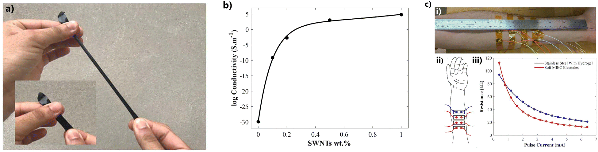 | ||
| Fig. 34 (a) Soft MIEC electrode material unstretched and stretched; (b) log conductivity versus SWNTs wt% graph. Percolation thresholds obtained from bulk conductivity versus loading of SWNTs. All data were fit with a two-term exponential model. SWNTs (c) able-bodied test of resistance versus peak current of soft MIEC electrodes and state-of-the-art stainless-steel with hydrogel electrodes: (i) a picture of the test subject's forearm with the soft MIEC electrodes and state-of-the-art stainless-steel with hydrogel electrodes attached. (ii) Schematic of the arm with the soft MIEC electrodes (red) and state-of-the-art stainless-steel with hydrogel electrodes (blue) corresponding to the (iii) resistance versus pulse current intensity graph. Reproduced from ref. 277 with permission from John Wiley and Sons; copyright © 2020 Wiley-VCH GmbH. | ||
Recently, Hu et al.295 have introduced a natural polymer-based conductive hydrogel, obtained from HA, CHT, glycerol, and potassium chloride (KCl), with excellent mechanical properties, low water loss, and freeze-tolerance, and self-healing properties (Fig. 35). The introduction of KCl and glycerol to the HA/CHT matrix enabled the formation of additional cross-linking (both ionic and H-bond based) in the hydrogel (Fig. 35-I). The prepared hydrogel showed good elasticity and fatigue resistance under cyclic deformation (Fig. 35-IIa to c), and anti-drying properties (Fig. 35-IId), which guaranteed its unchanged electric properties. These properties, combined with the conductivity (63.8 mS cm−1) and good sensitivity (GF = 2.64), guaranteed the durability and stability of the proposed system during its application as a flexible and wearable strain sensor (Fig. 35-II), even under low temperature conditions (−37 °C).295
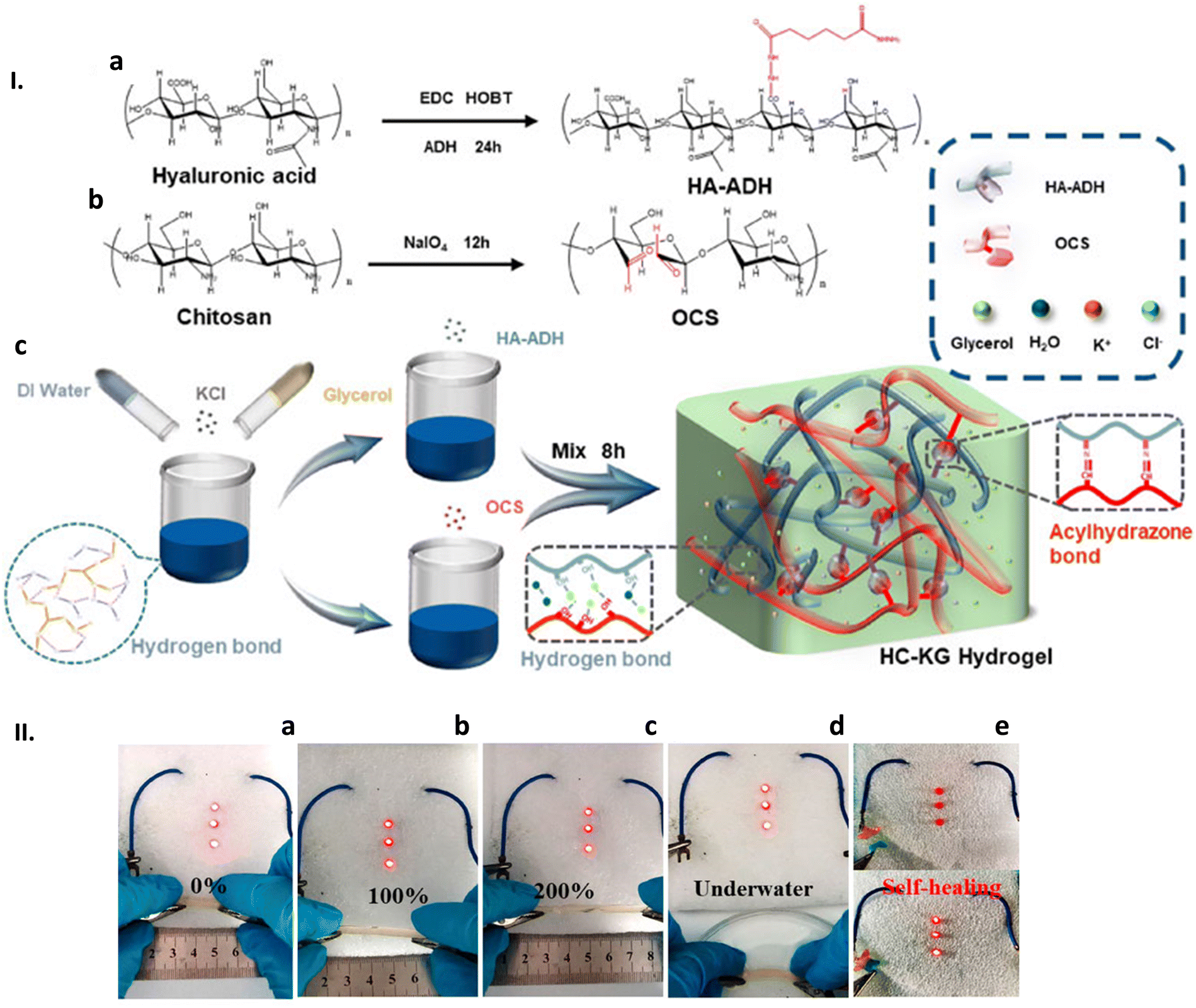 | ||
| Fig. 35 (I) Strategies for the fabrication of the stretchable, self-healing, conductive, and anti-freezing HC-KG hydrogel. The synthesis route of (a) HA-ADH and (b) OCS (c) of the preparation steps and the network structure of the HC-KG hydrogel. (II) The HC-KG hydrogel applied as a flexible electric wire to lighten the LEDs under different elongation of (a) 0%, (b) 100%, and (c) 200%; and (d) underwater condition. (e) The HC-KG hydrogel still exhibited good conductivity after its self-healing. Reproduced from ref. 295; copyright © 2017 The Authors. This work is licensed under a Creative Commons Attribution 4.0 CC-BY International License. | ||
A polyacrylamide (PAM)-based conductive self-healing hydrogel using DA-functionalized HA, borax as a dynamic cross-linker agent, and alkali cations Li+ and Na+ as conductive ions was investigated (Fig. 36-I).261 The novel self-adhesive conductive hydrogel, synthesised through free radical polymerization, was used as a flexible, wearable, and self-adhesive epidermal strain sensor (Fig. 36-III) for monitoring human motions, including bending and relaxation of fingers. Inspired by marine mussels, the DA-functionalized HA was chosen to provide strong adhesion (Fig. 36-II), displaying adhesion strength to the surface of glass and porcine skin on the order of ≈13.1 and 49.6 kPa, respectively (Fig. 36-II). The possible adhesion mechanism was attributed to H-bonding and van der Waals forces. In addition, the HAC–B–PAM hydrogel network presented high stretchability (up to 2800%), swelling, and toughness (42.4 kPa). The covalent and H-bond interactions formed between the HA and PAM networks contributed to the high tensile strength and fracture strain. The results showed that the hydrogel self-repair efficiency was ≈40% without any stimuli at room temperature (wound healing time 1 h). This finding was attributed to the reconstruction of multiple reversible boron ester bonds and weak H-bonds built by catechol groups of HA with borax and PAM. However, when the content of HA was increased to 6% wt, both the tensile strength and fracture strain of the hydrogel unexpectedly decreased to 31.5 kPa and 2700%, respectively. The relative resistance changes of the hydrogel under stretching displayed in Fig. 36-IIId show that the relative resistance increased as the tensile strain changed from 0 to 300%. The sensitive and stable strain sensors demonstrated remarkable recyclability, maintaining their performance across multiple cycles without notable losses. Even under low strain conditions (100% stretch-unload cycle), the sensors could be repeated numerous times within a span of 270 s without any significant alteration in the peak resistance. Furthermore, the strain-sensitive behaviour of the gel was examined within a circuit, alongside red diodes (Fig. 36-IIIe and f), affirming that these self-adhesive gels are optimal choices for constructing stretchable and wearable strain sensors.
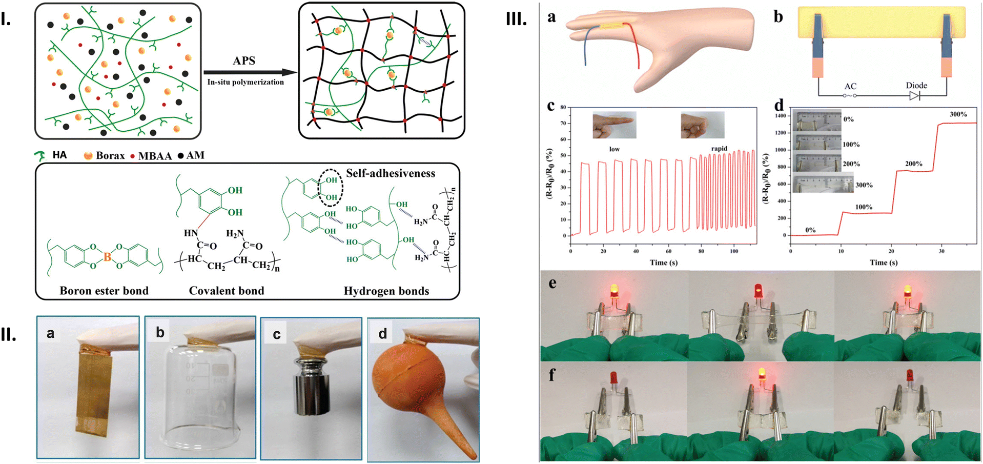 | ||
| Fig. 36 (I) Schematic diagram of the HA–B–PAM synthetic process and the interactions within the hydrogel network. The prepolymer forms a hydrogel through simple free radical polymerization, and various interactions occur within the network, including H-bonding, covalent bonding, and the formation of boron ester bonds. (II) HA–B–PAM hydrogel (column hydrogels with a diameter of 16 mm and a thickness of ≈ 5 mm) can adhere to various surfaces, including (a) Cu foil, (b) glass, (c) stainless steel, and (d) rubber. (III) Strain-sensitive performance of the hydrogel-based strain sensor. (a) and (b) Strain sensor detection model. (c) The relative resistance of the hydrogel changes with the extension and bending of the finger (low and rapid). The inset shows finger stretching and bending. (d) The relative resistance changes of the hydrogel under different elongations. The illustration shows the stretching of the hydrogel under different strains. (e) Photograph of the red diode brightness variation when the HA–B–PAM hydrogel is elongated. (f) Photograph of the red diode lighting up when the separated hydrogel is briefly reconnected. Reproduced from ref. 261 with permission from John Wiley and Sons, copyright © 2019 Wiley-VCH Verlag GmbH & Co. KGaA, Weinheim. | ||
HA-graft-DA and PDA-coated rGO were successfully combined through catechol cross-linking to obtain an injectable adhesive conductive hydrogel (Fig. 37-I).270
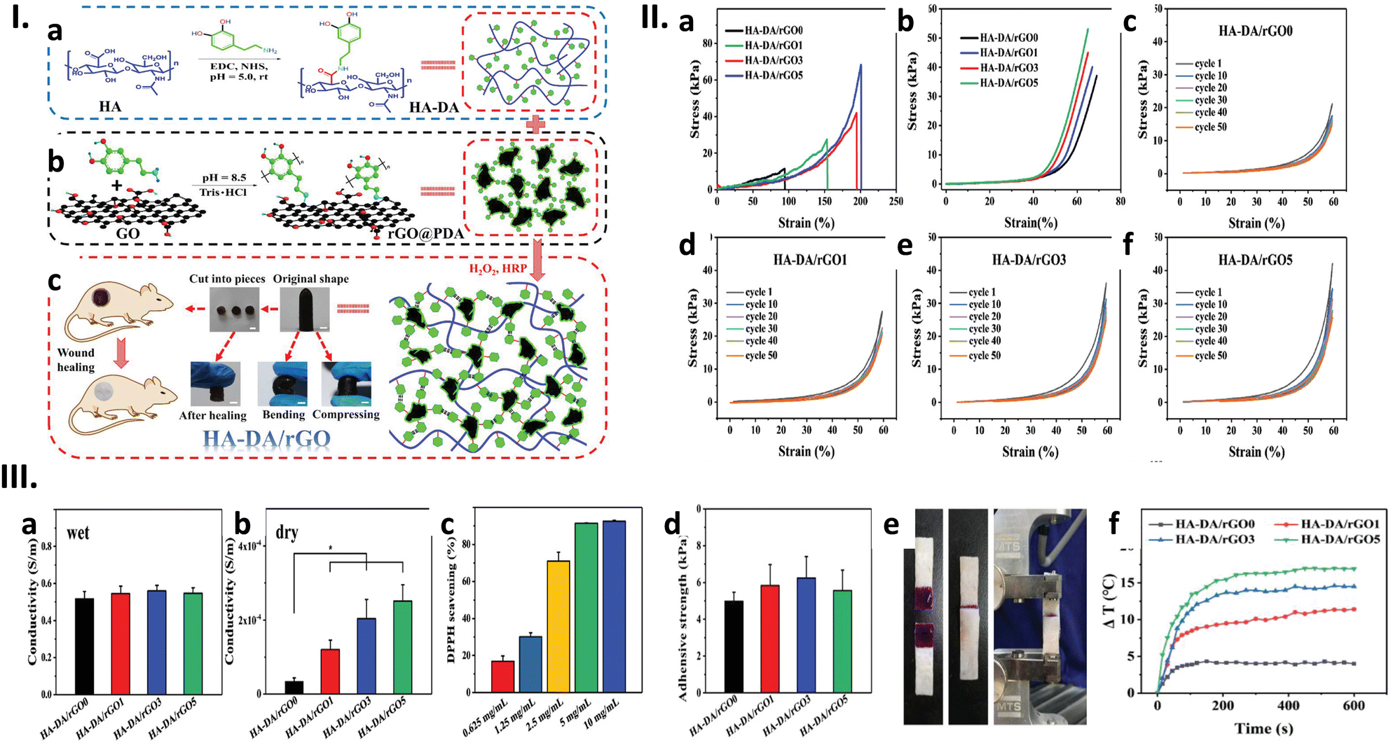 | ||
| Fig. 37 (I) Diagrammatic sketch of HA–DA/rGO hydrogel preparation. (a) Preparation scheme of HA–DA polymer and (b) rGO@PDA; (c) scheme of HA–DA/rGO hydrogel and the original, bending, compressing, self-healing representation, and its application in wound healing. Scale bar: 5 mm. (II) Mechanical characterization of HA–DA/rGO hydrogels. (a) The stress–strain profiles of the hydrogels though tensile tests; (b) stress–strain profiles of these hydrogel by compression. The cycling curves of stress–strain for the hydrogel (c) HA–DA/rGO0, (d) HA–DA/rGO1, (e) HA–DA/rGO3, and (f) HA–DA/rGO5 with compression strains of 60%. (III) Conductivity of the HA–DA/rGO hydrogels in a (a) wet state and (b) dry state; and (c) DPPH scavenging percentage by HA–DA/rGO3 hydrogels with different concentrations. (d) Adhesive strength of different hydrogels. (e) Photographs of the adhesive strength test. (f) The curves of ΔT-NIR irradiation time for the hydrogels under a light intensity of 1.0 W cm−2. Reproduced with adaptations from ref. 270 with permission from Wiley-VCH GmbH, copyright 2019. | ||
The HA–DA/rGO hydrogels were evaluated for wound healing application,261 presenting adhesive and suitable mechanical properties: excellent stretching (93.9–200.8%), compression (37.9 ± 0.7 kPa at a strain of 60%) and bending properties (Fig. 37-II). In addition, they exhibited good conductivity: the dry hydrogels presented ionic conductivities of ca. 1.2 × 10⁻³–2.5 × 10⁻³ mS cm−1; in the case of wet hydrogels, the conductivity increased to about 5 mS cm−1, which was mainly derived from the ionic conductivity of HA (Fig. 37-IIIa and b, respectively). The hydrogels also exhibited notable antioxidant activity, reaching values exceeding 90%, Fig. 37-IIIc. Additionally, they demonstrated good adhesive strength, ranging between 5.0 ± 0.5 and 6.3 ± 1.2 kPa (Fig. 37-IIId and e) and the core area experienced maximum temperatures ranging from 32 to 45 °C, resulting in temperature differentials (ΔT) between 3.9 and 17 °C. Notably, these heated core areas were surrounded by regions displaying a significant temperature gradient (Fig. 37-IIIf). Furthermore, even after undergoing 50 cycles of loading/unloading tests, the recovered hydrogels exhibited stress–strain curves akin to the original ones. This resilience underscores the hydrogel's commendable fatigue resistance, capable of withstanding external forces without fracturing and minimizing potential tissue damage. The adhesive mechanism can be reasonably attributed to imide formation or Michael-type reactions between catechol and quinone groups on rGO@PDA and HA–DA, with amino or thiol groups on the protein. Taken together, these findings underscore the potential of adhesive conductive haemostatic hydrogels with multifunctional capabilities as promising candidates for drug sustained release carriers and wound healing dressings.
Another hydrogel with DA-functionalized HA was developed by Zhang et al.,436 but using poly(acrylic acid) (PAA) instead of PAM, and Fe3+ as an ionic cross-linker, for adhesive and elastic strain. Once more, the functionalization of HA with DA resulted in a synergistic effect between the chemical cross-linking and noncovalent interactions, which facilitated a smooth stress-transfer, and consequently, contributed to high stretchability (800%), elasticity, and toughness. In addition, the abundant catechol groups and quinone groups on HA-graft-DA promoted durable self-adhesiveness to various substrates. The adhesion strength of the hydrogel to porcine skin, Zn sheet, and Teflon was 12.6 kPa, 33.2 kPa, and 11.1 kPa, respectively, which is relatively superior to the values detected for HA–DA/rGO hydrogels.270 The inter- and intrachain H-bonds within the matrix, along with multiple metal coordination interactions involving Fe3+, catechol, and carboxylic groups, collectively induced repeatable thermoplasticity and autonomous self-healing properties. More significantly, the material exhibited 97% mechanical recovery within 30 s and achieved electrical recovery with a rate of 98% within 2 s. When tested as strain sensors, the flexible hydrogels could distinctly perceive complex body motions, from subtle physiological signals like breathing, to more pronounced motions, like knee bending as human motion-detecting devices. Thus, these eco-friendly hydrogel ionotronic devices can be promising candidates for next-generation intelligent wearable devices and human–machine interfaces.
9. Future perspectives and conclusions
Slowly but steadily, GAGs are transitioning from biomaterials to advanced functional materials. Such a transition implies a shift in perspective, allowing them to go beyond their more traditional biological/medical functions. Fortunately, the advancements in polysaccharide science concerning the isolation and purification of GAGs, as well as the current possibilities of chemical modification in order to achieve “tailor-made” properties, are starting to captivate the attention of researchers and innovators operating outside the biomedical/wellness/healthcare domains.Case in point: the emergence and awareness of GAGs as a compelling alternative in the design of electroactive devices. This line of research has been autonomously developing through two main axes, which nonetheless share common points. For one, in bioelectronics and flexible electronics, they have found application in sensors, actuators, conductive inks, or as components of disposable devices. On the other hand, the incorporation of GAGs in more classic energy systems (e.g., batteries, fuel cells, electrochromic devices, and supercapacitors) and other electroactive devices have also been increasingly addressed. In both instances, GAGs have endowed these devices with advanced new functionalities and smart performances largely transcending the present ones.
The lion's share of this research effort has been centred on the development of conductive hydrogels. These hydrogels are particularly interesting, given their inherent versatility and multifaceted applications,539 and have not only become materials of choice in the design of systems for flexible electronics,50,51,252,372 but also a reliable and valuable option in the design of classical energy systems,520,540,541 aligning well with the growing demand for new clean methodologies and green technologies.438,542 Indeed, when summarising the tremendous changes in the way we have looked at, made, and used materials over the last few decades, the selection of materials stands as the most critical aspect, as it becomes absolutely crucial whenever ecologically sound, cost-effective, and flexible devices are at stake.
For GAGs to effectively transition into fully advanced functional materials, they need to be able to confront the current challenges. As such, it is necessary to thoroughly examine the benefits they can provide and the challenges such a solution poses to both the scientific and industrial communities.
The benefits should be clear by now: whether GAGs are used in their more traditional biomedical domains or in the more recent ones, their success as prime materials relies not only on their chemical properties, biocompatibility, and reactivity but also on their ability to be assembled into networks and branched systems and, ultimately, be used as building blocks for higher complexity systems.543
The challenges that need to be overcome are also tremendous and require compulsory, continued research and development efforts. These comprise key issues regarding isolation and purification, the development of unexpensive synthetic GAG-analogues, the structural modification and functionalization of GAGs, and extending to device fabrication techniques and performance optimization. The long-term stability of GAG-based materials in energy systems is also essential for their practical implementation. Research should focus on understanding and mitigating degradation mechanisms that can occur over extended cycling or operation periods. Improvements in the stability of GAG-based electrode materials, electrolytes, and device interfaces are necessary to ensure sustained performance and prolonged device lifespan. The incorporation of GAGs in classic energy systems should also consider compatibility and integration with existing materials and technologies. This implies both a better understanding of their physical–chemical properties at all levels of complexity (from the disaccharide units to the polymeric chains to their role as components in complex systems) and the exploration of methods to efficiently interface GAG-based materials with other components of the energy system, such as current collectors, separators, and catalysts. Compatibility considerations are critical for achieving seamless integration and optimal performance of GAG-based energy devices.
It is, thus, encouraging to see that GAGs offer an attractive alternative in such a demanding field as that of electroactive systems. Either by operating in highly demanding environments such as those experienced in fuel cells or even batteries (which are much more aggressive than their native biological ones), or by helping transform conventional devices into self-healing, stretchable/compressible systems, GAGs’ unique features have proven them to be up to the task, something which would have been unthinkable a few years ago.
The insight and skills gained from studying GAGs in the framework of bioelectronics and flexible electronics can be applied to further improve their performance and expand their applications in energy devices or, even, in other fields. Initiatives, such as the Research Roadmap 2040 of the European Polysaccharide Network of Excellence, will undoubtedly contribute as well.33 The biomedical/wellness/healthcare industry has already laid some groundwork, particularly concerning the manufacture of high-quality standard GAG materials and their effective application in industrial processes. These processes can and should be taken advantage of—whenever possible—when building any kind of roadmap for the effective implementation of GAGs as viable electroactive biomaterials.
Transitioning GAG-based technologies from the research laboratory to industrial-scale production will be another pivotal milestone to address. Laboratory-scale devices might have come a long way, but to show true industrial potential, there is a need to transition from such small-area devices to larger ones, as well as to start to implement integration processes that will allow the bridging between single and multiple cells. Developing scalable and cost-effective manufacturing processes for GAG-based materials and devices will be fundamental in facilitating widespread adoption in commercial applications.
And finally, public opinion needs to be addressed and positively influenced. If the current materials revolution has been fuelled by an increasing ongoing demand for bio-based, affordable, and highly functional materials,33 ultimately, R&D needs to be oriented toward the creation of specialty products or high-value-added sustainable products for innovative applications.34
While we may consider that the incorporation of GAGs as components of traditional energy devices is still in its infancy, it is clear that the future of such systems is bright. GAG's intrinsic properties, in tandem with the current biotechnological processes, have already allowed us to come this far. As the paradigm of GAGs as solely biomaterials continues to shift, so too will the ensuing research efforts continue to expand and push the boundaries of these materials’ possibilities even further,438 opening up even more avenues for interdisciplinary approaches and original solutions in healthcare, consumer electronics, and beyond.
Author contributions
F. M. Santos: conceptualization, data curation, formal analysis, and writing (first draft and revision). S. C. Nunes: formal analysis and writing (first draft and revision). V. de Z. Bermudez: formal analysis, writing (first draft and revision), and supervision.Data availability
No primary research results, software or code have been included and no new data were generated or analysed as part of this review.Conflicts of interest
There are no conflicts to declare.Acknowledgements
This research was financed by project A-MoVeR – “Mobilizing Agenda for the Development of Products & Systems towards an Intelligent and Green Mobility”, operation no. 02/C05-i01.01/2022.PC646908627-00000069, approved under the terms of the call no. 02/C05-i01/2022 – Mobilizing Agendas for Business Innovation, financed by European funds provided to Portugal by the Recovery and Resilience Plan (RRP), in the scope of the European Recovery and Resilience Facility (RRF), framed in the Next Generation UE, for the period from 2021–2026. The authors acknowledge the contribution of project SOLPOWINS (PTDC/CTM-REF/4304/2020), financed by national funds from the Foundation for Science and Technology (FCT), project OBTAIN (NORTE-01-0145-FEDER-000084), co-financed by the European Regional Development Fund (ERDF) through NORTE 2020 (Northern Regional Operational Program 2014/2020), project Centro de Química-Vila Real (CQ-VR) (UIDB/00616/2020 (https://doi.org/10.54499/UIDB/00616/2020) and UIDP/00616/2020 (https://doi.org/10.54499/UIDP/00616/2020)) and project Fiber Materials and Environmental Technologies (FibEnTech-UBI) (UIDB/00195/2020; https://doi.org/10.54499/UIDB/00195/2020), financed by national funds through the FCT/MCTES (PIDDAC). S. C. Nunes acknowledges the FCT for the Assistant Research contract (2020-00805.CEEIND; https://doi.org/10.54499/2020.00805.CEECIND/CP1625/CT0001) in the scope of the Scientific Employment Stimulus. F. M. Santos acknowledges the SOLPOWINS project for his Assistant Research contract.Notes and references
- M. Bresadola, Medicine and science in the life of Luigi Galvani (1737–1798), Brain Res. Bull., 1998, 46(5), 367–380 Search PubMed.
- M. Piccolino, Luigi Galvani's path to animal electricity, C. R. Biol., 2006, 329(5–6), 303–318 Search PubMed.
- M. Jia and M. Rolandi, Soft and ion-conducting materials in bioelectronics: from conducting polymers to hydrogels, Adv. Healthcare Mater., 2020, 9(5), 1901372 Search PubMed.
- M. Muskovich and C. J. Bettinger, Biomaterials-based electronics: polymers and interfaces for biology and medicine, Adv. Healthcare Mater., 2012, 1(3), 248–266 Search PubMed.
- S. E. B. Tyler, Nature's electric potential: A systematic review of the role of bioelectricity in wound healing and regenerative processes in animals, humans, and plants, Front. Physiol., 2017, 8, 627 Search PubMed.
- G. R. A. de Toledo, A. G. Parise, F. Z. Simmi, A. V. L. Costa, L. G. S. Senko, M. W. Debono and G. M. Souza, Plant electrome: the electrical dimension of plant life, Theor. Exp. Plant Physiol., 2019, 31(1), 21–46 Search PubMed.
- E. E. Josberger, P. Hassanzadeh, Y. Deng, J. Sohn, M. J. Rego, C. T. Amemiya and M. Rolandi, Proton conductivity in ampullae of Lorenzini jelly, Sci. Adv., 2016, 2(5), e1600112 Search PubMed.
- X. Zhang, K. Xia, L. Lin, F. Zhang, Y. Yu, K. S. Ange, X. Han, E. Edsinger, J. Sohn and R. J. Linhardt, Structural and functional components of the skate sensory organ ampullae of Lorenzini, ACS Chem. Biol., 2018, 13(6), 1677–1685 Search PubMed.
- Y. Sone, P. Ekdunge and D. Simonsson, Proton conductivity of Nafion 117 as measured by a four-electrode AC impedance method, J. Electrochem. Soc., 1996, 143(4), 1254 Search PubMed.
- M. Irimia-Vladu, “Green” electronics: biodegradable and biocompatible materials and devices for sustainable future, Chem. Soc. Rev., 2014, 43(2), 588–610 Search PubMed.
- A. Kafy, H.-U. Ko, H. C. Kim, S. Mun, L. Zhai and J. Kim, Renewable smart materials, Smart Mater. Struct., 2016, 25(7), 073001 Search PubMed.
- K. Sharma, Carbohydrate-to-hydrogen production technologies: a mini-review, Renewable Sustainable Energy Rev., 2019, 105, 138–143 Search PubMed.
- R. Singh and H.-W. Rhee, The rise of bio-inspired energy devices, Energy Storage Mater., 2019, 23, 390–408 Search PubMed.
- L. Lan, J. Ping, J. Xiong and Y. Ying, Sustainable natural bio-origin materials for future flexible devices, Adv. Sci., 2023, 9(15), 2200560 Search PubMed.
- United Nations World Commission on Environment and Development, Brundtland Report: Our Common Future, Oxford University Press, Oxford, 1987 Search PubMed.
- United Nations, The sustainable development goals report 2016. United Nations, New York, USA, 2016, pp. 1–56 Search PubMed.
- A. Guterres, Remarks to International Energy Agency Clean Energy Transition Summit, 2020 Search PubMed.
- J. R. Jambeck, R. Geyer, C. Wilcox, T. R. Siegler, M. Perryman, A. Andrady, R. Narayan and K. L. Law, Plastic waste inputs from land into the ocean, Science, 2015, 347(6223), 768–771 Search PubMed.
- R. A. Sheldon and M. Norton, Green chemistry and the plastic pollution challenge: towards a circular economy, Green Chem., 2020, 22(19), 6310–6322 Search PubMed.
- Y. Zhu, C. Romain and C. K. Williams, Sustainable polymers from renewable resources, Nature, 2016, 540, 354–362 Search PubMed.
- F. Perera, Pollution from fossil-fuel combustion is the leading environmental threat to global pediatric health and equity: Solutions exist, Int. J. Environ. Res. Public Health, 2018, 15(1), 16 Search PubMed.
- J. Garner and K. Park, Chemically modified natural polysaccharides to form gels, ed. K. G. Ramawat and J.-M. Mérillon, Springer International Publishing, Cham, 2014, pp. 1–25 Search PubMed.
- S. Vandghanooni and M. Eskandani, Electrically conductive biomaterials based on natural polysaccharides: challenges and applications in tissue engineering, Int. J. Biol. Macromol., 2019, 141, 636–662 Search PubMed.
- M. Diener, J. Adamcik, A. Sánchez-Ferrer, F. Jaedig, L. Schefer and R. Mezzenga, Primary, secondary, tertiary and quaternary structure levels in linear polysaccharides: from random coil, to single helix to supramolecular assembly, Biomacromolecules, 2019, 20(4), 1731–1739 Search PubMed.
- L. Yang and L. M. Zhang, Chemical structural and chain conformational characterization of some bioactive polysaccharides isolated from natural sources, Carbohydr. Polym., 2009, 76(3), 349–361 Search PubMed.
- G. Fittolani, P. H. Seeberger and M. Delbianco, Helical polysaccharides, Pept. Sci., 2020, 112(1), e24124 Search PubMed.
- Y. Yu and M. Delbianco, Conformational studies of oligosaccharides, Chem. – Eur. J., 2020, 26(44), 9814–9825 Search PubMed.
- H. A. Pawar, S. R. Kamat and P. D. Choudhary, An overview of natural polysaccharides as biological macromolecules: Their chemical modifications and pharmaceutical applications, Biol. Med., 2015, 7(1), 1000224 Search PubMed.
- S. Li, Q. Xiong, X. Lai, X. Li, M. Wan, J. Zhang, Y. Yan, M. Cao, L. Lu, J. Guan, D. Zhang and Y. Lin, Molecular modification of polysaccharides and resulting bioactivities, Compr. Rev. Food Sci. Food Saf., 2016, 15(2), 237–250 Search PubMed.
- Y. Xu, Y.-j Wu, P.-l Sun, F. Zhang, R. J. Linhardt and A.-q Zhang, Chemically modified polysaccharides: Synthesis, characterization, structure activity relationships of action, Int. J. Biol. Macromol., 2019, 132, 970–977 Search PubMed.
- M. Zhu and J. Liu, Research progress in bio-based self-healing materials, Eur. Polym. J., 2020, 109651 Search PubMed.
- R. A. Sheldon, The road to biorenewables: carbohydrates to commodity chemicals, ACS Sustainable Chem. Eng., 2018, 6(4), 4464–4480 Search PubMed.
- M. Gericke, A. J. R. Amaral, T. Budtova, P. De Wever, T. Groth, T. Heinze, H. Höfte, A. Huber, O. Ikkala, J. Kapuśniak, R. Kargl, J. F. Mano, M. Másson, P. Matricardi, B. Medronho, M. Norgren, T. Nypelö, L. Nyström, A. Roig, M. Sauer, H. A. Schols, J. van der Linden, T. M. Wrodnigg, C. Xu, G. E. Yakubov, K. Stana Kleinschek and P. Fardim, The European Polysaccharide Network of Excellence (EPNOE) research roadmap 2040: Advanced strategies for exploiting the vast potential of polysaccharides as renewable bioresources, Carbohydr. Polym., 2024, 326, 121633 Search PubMed.
- S. Rebouillat and F. Pla, A review: on smart materials based on some polysaccharides; within the contextual bigger data, insiders, “improvisation” and said artificial intelligence trends, J. Biomater. Nanobiotechnol., 2019, 10(02), 41–77 Search PubMed.
- J. V. Maciel, A. M. M. Durigon, M. M. Souza, R. F. N. Quadrado, A. R. Fajardo and D. Dias, Polysaccharides derived from natural sources applied to the development of chemically modified electrodes for environmental applications: A review, Trends Environ. Anal. Chem., 2019, 22, e00062 Search PubMed.
- T. Selvaraj, V. Perumal, S. F. Khor, L. S. Anthony, S. C. B. Gopinath and N. Muti Mohamed, The recent development of polysaccharides biomaterials and their performance for supercapacitor applications, Mater. Res. Bull., 2020, 126, 110839 Search PubMed.
- W. Schlemmer, J. Selinger, M. A. Hobisch and S. Spirk, Polysaccharides for sustainable energy storage—A review, Carbohydr. Polym., 2021, 265, 118063 Search PubMed.
- F. G. Torres and G. E. De-la-Torre, Polysaccharide-based triboelectric nanogenerators: a review, Carbohydr. Polym., 2021, 251, 117055 Search PubMed.
- V. L. Finkenstadt, Natural polysaccharides as electroactive polymers, Appl. Microbiol. Biotechnol., 2005, 67(6), 735–745 Search PubMed.
- A. Rußler and T. Rosenau, Electrical Conductivity and Polysaccharides, in Polysaccharide Building Blocks: A Sustainable Approach to the Development of Renewable Biomaterials, ed. Y. Habibi and L. A. Lucia, John Wiley & Sons, Inc., Hoboken, New Jersey, 2012, pp. 247–270 Search PubMed.
- D. Pal and S. Saha, Chondroitin: a natural biomarker with immense biomedical applications, RSC Adv., 2019, 9(48), 28061–28077 Search PubMed.
- S. Morla, Glycosaminoglycans and glycosaminoglycan mimetics in cancer and inflammation, Int. J. Mol. Sci., 2019, 20(8), 1963 Search PubMed.
- A. Köwitsch, G. Zhou and T. Groth, Medical application of glycosaminoglycans: a review, J. Tissue Eng. Regener. Med., 2018, 12(1), e23–e41 Search PubMed.
- C. He, H. Ji, Y. Qian, Q. Wang, X. Liu, W. Zhao and C. Zhao, Heparin-based and heparin-inspired hydrogels: size-effect, gelation and biomedical applications, J. Mater. Chem. B, 2019, 7(8), 1186–1208 Search PubMed.
- S. Vasvani, P. Kulkarni and D. Rawtani, Hyaluronic acid: a review on its biology, aspects of drug delivery, route of administrations and a special emphasis on its approved marketed products and recent clinical studies, Int. J. Biol. Macromol., 2020, 151, 1012–1029 Search PubMed.
- P. Yang, Y. Lu, W. Gou, Y. Qin, J. Tan, G. Luo and Q. Zhang, Glycosaminoglycans’ ability to promote wound healing: from native living macromolecules to artificial biomaterials, Adv. Sci., 2023, 2305918 Search PubMed.
- F. M. Santos, P. C. Barbosa, R. F. P. Pereira, M. Manuela Silva, H. M. R. Gonçalves, S. C. Nunes, F. M. L. Figueiredo, A. J. M. Valente and V. de Zea Bermudez, Proton conducting electrolytes composed of chondroitin sulfate polysaccharide and citric acid, Eur. Polym. J., 2020, 124, 109453 Search PubMed.
- R. L. Cleland, M. C. Cleland, J. J. Lipsky and V. E. Lyn, Ionic polysaccharides. I. Adsorption and fractionation of polyelectrolytes on (diethylamino)ethyl cellulose, J. Am. Chem. Soc., 1968, 90(12), 3141–3146 Search PubMed.
- E. Seyrek and P. Dubin, Glycosaminoglycans as polyelectrolytes, Adv. Colloid Interface Sci., 2010, 158(1–2), 119–129 Search PubMed.
- V. Castrejón-Comas, C. Alemán and M. D. M. Pérez-Madrigal, Multifunctional conductive hyaluronic acid hydrogels for wound care and skin regeneration, Biomater. Sci., 2023, 11(7), 2266–2276 Search PubMed.
- L. Schöbel and A. R. Boccaccini, A review of glycosaminoglycan-modified electrically conductive polymers for biomedical applications, Acta Biomater., 2023, 169, 45–65 Search PubMed.
- B. Chakrabarti, J. W. Park and E. S. Stevens, Glycosaminoglycans: structure and interaction, CRC Crit. Rev. Biochem., 1980, 8(3), 225–313 Search PubMed.
- R. L. Jackson, S. J. Busch and A. D. Cardin, Glycosaminoglycans: molecular properties, protein interactions, and role in physiological processes, Physiol. Rev., 1991, 71(2), 481–539 Search PubMed.
- W. D. Comper, Extracellular matrix interactions: Sulfation of connective tissue polysaccharides creates macroion binding templates and conditions for dissipative structure formation, J. Theor. Biol., 1990, 145(4), 497–509 Search PubMed.
- T. Miller, M. C. Goude, T. C. McDevitt and J. S. Temenoff, Molecular engineering of glycosaminoglycan chemistry for biomolecule delivery, Acta Biomater., 2014, 10(4), 1705–1719 Search PubMed.
- P. L. DeAngelis, J. Liu and R. J. Linhardt, Chemoenzymatic synthesis of glycosaminoglycans: re-creating, re-modeling and re-designing nature's longest or most complex carbohydrate chains, Glycobiology, 2013, 23(7), 764–777 Search PubMed.
- R. Menezes, R. Vincent, L. Osorno, P. Hu and T. L. Arinzeh, Biomaterials and tissue engineering approaches using glycosaminoglycans for tissue repair: Lessons learned from the native extracellular matrix, Acta Biomater., 2023, 163, 210–227 Search PubMed.
- K. J. Wolf and S. Kumar, Hyaluronic acid: incorporating the bio into the material, ACS Biomater. Sci. Eng., 2019, 5(8), 3753–3765 Search PubMed.
- A. J. Hayes and J. Melrose, Electro-stimulation, a promising therapeutic treatment modality for tissue repair: emerging roles of sulfated glycosaminoglycans as electro-regulatory mediators of intrinsic repair processes, Adv. Therapeutics, 2020, 3(11), 2000151 Search PubMed.
- I. Capila and R. J. Linhardt, Heparin-protein interactions, Angew. Chem., Int. Ed., 2002, 41(3), 391–412 Search PubMed.
- R. M. Lauder, Chondroitin sulphate: a complex molecule with potential impacts on a wide range of biological systems, Complementary Ther. Med., 2009, 17(1), 56–62 Search PubMed.
- J. M. Trownbridge and R. L. Gallo, Dermatan sulfate: new functions from an old glycosaminoglycan, Glycobiology, 2002, 12(9), 117R–125R Search PubMed.
- D. Soares da Costa, R. L. Reis and I. Pashkuleva, Sulfation of glycosaminoglycans and Its implications in human health and disorders, Annu. Rev. Biomed. Eng., 2017, 19, 1–26 Search PubMed.
- B. Caterson and J. Melrose, Keratan sulfate, a complex glycosaminoglycan with unique functional capability, Glycobiology, 2018, 28(4), 182–206 Search PubMed.
- I. Hargittai and M. Hargittai, Molecular structure of hyaluronan: an introduction, Struct. Chem., 2008, 19(5), 697–717 Search PubMed.
- H. Knopf-Marques, M. Pravda, L. Wolfova, V. Velebny, P. Schaaf, N. E. Vrana and P. Lavalle, Hyaluronic acid and its derivatives in coating and delivery systems: applications in tissue engineering, regenerative medicine and immunomodulation, Adv. Healthcare Mater., 2016, 5(22), 2841–2855 Search PubMed.
- G. Lamm and G. R. Pack, Counterion condensation and shape within Poisson–Boltzmann theory, Biopolymers, 2010, 93(7), 619–639 Search PubMed.
- I. Kanungo, N. N. Fathima and J. R. Rao, Dielectric behavior of gelatine–glycosaminoglycans blends: An impedance analysis, Mater. Sci. Eng.: C, 2013, 33(4), 2455–2459 Search PubMed.
- P. L. Chandran and F. Horkay, Aggrecan, an unusual polyelectrolyte: review of solution behavior and physiological implications, Acta Biomater., 2012, 8(1), 3–12 Search PubMed.
- J. Selberg, M. Jia and M. Rolandi, Proton conductivity of glycosaminoglycans, PLoS One, 2019, 14(3), 1–8 Search PubMed.
- E. Bedini, A. Laeazza and A. Iadonisi, Chemical derivatization of sulfated glycosaminoglycans, Eur. J. Org. Chem., 2016, 3018–3042 Search PubMed.
- A. Fallacara, E. Baldini, S. Manfredini and S. Vertuani, Hyaluronic acid in the third millennium, Polymers, 2018, 10(7), 701 Search PubMed.
- B. Casu, Structure and biological activity of mammalian glycosaminoglycans, Mod. Probl. Pharmacopsychiatry, 1989, 23, 56–67 Search PubMed.
- A. Almond and J. K. Sheehan, Glycosaminoglycan conformation: Do aqueous molecular dynamics simulations agree with X-ray fiber diffraction?, Glycobiology, 2000, 10(3), 329–338 Search PubMed.
- R. P. Richter, N. S. Baranova, A. J. Day and J. C. F. Kwok, Glycosaminoglycans in extracellular matrix organisation: are concepts from soft matter physics key to understanding the formation of perineuronal nets?, Curr. Opin. Struct. Biol., 2018, 50, 65–74 Search PubMed.
- B. Nagarajan, N. V. Sankaranarayanan and U. R. Desai, Perspective on computational simulations of glycosaminoglycans, Wiley Interdiscip. Rev.: Comput. Mol. Sci., 2019, 9(2), 1–35 Search PubMed.
- B. Casu, Structure and biological activity of heparin and other glycosaminoglycans, Pharmacol. Res. Commun., 1979, 11(1), 1–18 Search PubMed.
- F. Ganji, S. Vasheghani-Farahani and E. Vasheghani-Farahani, Theoretical description of hydrogel swelling: a review, Iran. Polym. J., 2010, 19(5), 375–398 Search PubMed.
- J. E. Scott, C. Cummings, A. Brass and Y. Chen, Secondary and tertiary structures of hyaluronan in aqueous solution, investigated by rotary shadowing-electron microscopy and computer simulation. Hyaluronan is a very efficient network-forming polymer, Biochem. J., 1991, 274(3), 699–705 Search PubMed.
- J. E. Scott, Supramolecular organization of extracellular matrix glycosaminoglycans, in vitro and in the tissues, FASEB J., 1992, 6(9), 2639–2645 Search PubMed.
- S.-P. Rwei, S.-W. Chen, C.-F. Mao and H.-W. Fang, Viscoelasticity and wearability of hyaluronate solutions, Biochem. Eng. J., 2008, 40(2), 211–217 Search PubMed.
- P. Snetkov, K. Zakharova, S. Morozkina, R. Olekhnovich and M. Uspenskaya, Hyaluronic acid: the influence of molecular weight on structural, physical, physico-chemical, and degradable properties of biopolymer, Polymers, 2020, 12(8), 1800 Search PubMed.
- D. A. Gibbs, E. W. Merrill, K. A. Smith and E. A. Balazs, Rheology of hyaluronic acid, Biopolymers, 1968, 6(6), 777–791 Search PubMed.
- E. A. Balazs and J. Cui, The story of “hyaluronan putty”, Bioact. Carbohydr. Diet. Fibre, 2013, 2(2), 143–151 Search PubMed.
- E. P. van Dam, G. Giubertoni, F. Burla, G. H. Koenderink and H. J. Bakker, Hyaluronan biopolymers release water upon pH-induced gelation, Phys. Chem. Chem. Phys., 2020, 22(16), 8667–8671 Search PubMed.
- G. Giubertoni, F. Burla, C. Martinez-Torres, B. Dutta, G. Pletikapic, E. Pelan, Y. L. A. Rezus, G. H. Koenderink and H. J. Bakker, Molecular origin of the elastic state of aqueous hyaluronic acid, J. Phys. Chem. B, 2019, 123(14), 3043–3049 Search PubMed.
- F. Horkay, J. F. Douglas and S. R. Raghavan, Rheological Properties of Cartilage Glycosaminoglycans and Proteoglycans, Macromolecules, 2021, 54(5), 2316–2324 Search PubMed.
- S. J. Kim, C.-K. Lee and S. I. Kim, Characterization of the water state of hyaluronic acid and poly(vinyl alcohol) interpenetrating polymer networks, J. Appl. Polym. Sci., 2004, 92(3), 1467–1472 Search PubMed.
- I. Gatej, M. Popa and M. Rinaudo, Role of the pH on hyaluronan behavior in aqueous solution, Biomacromolecules, 2005, 6(1), 61–67 Search PubMed.
- N. Volpi, A. Mucci and L. Schenetti, Stability studies of chondroitin sulfate, Carbohydr. Res., 1999, 315(3), 345–349 Search PubMed.
- K. A. Jandik, D. Kruep, M. Cartier and R. J. Linhardt, Accelerated stability studies of heparin, J. Pharm. Sci., 1996, 85(1), 45–51 Search PubMed.
- B. A. Gomes de Melo and M. H. Andrade Santana, Structural modifications and solution behavior of hyaluronic acid degraded with high pH and temperature, Appl. Biochem. Biotechnol., 2019, 189(2), 424–436 Search PubMed.
- R. Stern, G. Kogan, J. J. Mark and L. Šoltés, The many ways to cleave hyaluronan, Biotechnol. Adv., 2007, 25(6), 537–557 Search PubMed.
- B. Fuchs and J. Schiller, Glycosaminoglycan degradation by selected reactive oxygen species, Antioxid. Redox Signaling, 2014, 21(7), 1044–1062 Search PubMed.
- B. J. Parsons, Oxidation of glycosaminoglycans by free radicals and reactive oxidative species: a review of investigative methods, Free Radical Res., 2015, 49(5), 618–632 Search PubMed.
- S. Ernst, R. Langer, C. L. Cooney and R. Sasisekharan, Enzymatic degradation of glycosaminogIycans, Crit. Rev. Biochem. Mol. Biol., 1995, 30(5), 387–444 Search PubMed.
- N. Jouon, M. Rinaudo, M. Milas and J. Desbrieres, Hydration of hyaluronic acid as a function of the counterion type and relative humidity, Carbohydr. Polym., 1995, 26(1), 69–73 Search PubMed.
- A. Průšová, F. J. Vergeldt and J. Kučerik, Influence of water content and drying on the physical structure of native hyaluronan, Carbohydr. Polym., 2013, 95(1), 515–521 Search PubMed.
- A. K. Mitra, S. Arnott, R. P. Millane, S. Saghunathan and J. K. Sheehan, Comparison of glycosaminoglycan structures induced by different monovalent cations as determined by X-ray fiber diffraction, J. Macromol. Sci., B: Phys., 1985, 24(1–4), 21–38 Search PubMed.
- Y. V. Chudinova, D. V. Kurek and V. P. Varlamov, Molecular architecture of natural polysaccharide based thin films, Solid State Phenomena, Trans Tech Publications Ltd, 2017, pp. 358–361 Search PubMed.
- M. Yamazaki and K. Iijima, Fabrication and characterization of polysaccharide composite films from polyion complex particles, Polymers, 2020, 12(2), 435 Search PubMed.
- L. Gřundělová, A. Gregorova, A. Mráček, R. Vícha, P. Smolka and A. Minařík, Viscoelastic and mechanical properties of hyaluronan films and hydrogels modified by carbodiimide, Carbohydr. Polym., 2015, 119, 142–148 Search PubMed.
- P. Smolka, M. Kadlečková, K. Kocourková, M. Bartoňová, F. Mikulka, E. Knechtová, A. Mráček, L. Musilová, M. Humenik and A. Minařík, Controlled Structuring of Hyaluronan Films by Phase Separation and Inversion, Langmuir, 2023, 39(37), 13140–13148 Search PubMed.
- E. Hrabárová, J. Rychlý, V. Sasinková, K. Valachová, I. Janigová, K. Csomorová, I. Juránek and L. Šoltés, Structural characterisation of thiol-modified hyaluronans, Cellulose, 2012, 19(6), 2093–2104 Search PubMed.
- K. Benešová, M. Pekař, L. Lapčík and J. Kučerik, Stability evaluation of n-alkyl hyaluronic acid derivates by DSC and TG measurement, J. Therm. Anal. Calorim., 2006, 83(2), 341–348 Search PubMed.
- F. Sun and I. Zhitomirsky, Electrochemical deposition of composite biopolymer films, Surf. Eng., 2010, 26(7), 546–551 Search PubMed.
- I. Šimkovic, R. Mendichi, I. Kelnar, J. Filip and M. Hricovíni, Cationization of heparin for film applications, Carbohydr. Polym., 2015, 115, 551–558 Search PubMed.
- N. C. Pan, G. T. Bersaneti, S. Mali and M. A. P. C. Celligoi, Films based on blends of polyvinyl alcohol and microbial hyaluronic acid, Braz. Arch. Biol. Technol., 2020, 63, e2019038 Search PubMed.
- Q. Shen, C. Zhang, H. Mo, H. Zhang, X. Qin, J. Li, Z. Zhang and A. Richel, Fabrication of chondroitin sulfate calcium complex and its chondrocyte proliferation in vitro, Carbohydr. Polym., 2021, 254, 117282 Search PubMed.
- M. Iijima, T. Hatakeyama and H. Hatakeyama, DSC and TMA studies of polysaccharide physical hydrogels, Anal. Sci., 2021, 37(1), 211–219 Search PubMed.
- X. Meng and J. E. Kevin, “Click” reactions in polysaccharide modification, Prog. Polym. Sci., 2016, 53, 52–85 Search PubMed.
- A. Kirschning, N. Dibbert and G. Dräger, Chemical functionalization of polysaccharides—towards biocompatible hydrogels for biomedical Applications, Chem. – Eur. J., 2018, 24(6), 1231–1240 Search PubMed.
- L. A. Pérez, R. Hernández, J. M. Alonso, R. Pérez-González and V. Sáez-Martínez, Hyaluronic acid hydrogels crosslinked in physiological conditions: synthesis and biomedical applications, Biomedicines, 2021, 9, 9 Search PubMed.
- P. Colomban and A. Novak, Defects, non-stoichiometry and phase transitions, in Proton Conductors: Solids, Membranes and Gels—Materials and Devices, ed. P. Colomban, Cambridge University Press, Cambridge, 1992, pp. 61–78 Search PubMed.
- P. Colomban and A. Novak, Conductivity mechanisms and models in anhydrous protonic conductors, in Proton Conductors: Solids, Membranes and Gels—Materials and Devices, ed. P. Colomban, Cambridge University Press, Cambridge, 1992, pp. 457–473 Search PubMed.
- P. Colomban, Proton and protonic species: the hidden face of solid state chemistry. How to measure H-content in materials?, Fuel Cells, 2013, 13(1), 6–18 Search PubMed.
- K.-D. Kreuer, Proton conductivity: materials and applications, Chem. Mater., 1996, 8(3), 610–641 Search PubMed.
- S. F. Fischer, G. L. Hofacker and J. R. Sabin, Proton–phonon coupling in a hydrogen bonded system, Phys. Kondens. Mater., 1969, 8(4), 268–278 Search PubMed.
- K.-D. Kreuer, Vehicle mechanism, a new model for the interpretation of the conductivity of fast proton vonductors, Angew. Chem., Int. Ed. Engl., 1982, 21(3), 208–209 Search PubMed.
- C. J. T. de Grotthuss, Sur la décomposition de l’eau et des corps qu’elle tient en dissolution à l’aide de l’électricité galvanique, Ann. Chim., 1806, 58(1806), 54–73 Search PubMed.
- T. Ogawa, K. Kamiguchi, T. Tamaki, H. Imai and T. Yamaguchi, Differentiating Grotthuss proton conduction mechanisms by nuclear magnetic resonance spectroscopic analysis of frozen samples, Anal. Chem., 2014, 86(19), 9362–9366 Search PubMed.
- G. N. Pairas and K. Shankar, H-Bond: the chemistry-biology H-bridge, Chem. Select, 2016, 1(15), 4520–4532 Search PubMed.
- H. Ishikita and K. Saito, Proton transfer reactions and hydrogen-bond networks in protein environments, J. R. Soc., Interface, 2014, 11(91), 20130518 Search PubMed.
- A.-N. Bondar and M. J. Lemieux, Reactions at biomembrane interfaces, Chem. Rev., 2019, 119(9), 6162–6183 Search PubMed.
- Y. Agam, R. Nandi, T. Bulava and N. Amdursky, The role of the protein–water interface in dictating proton conduction across protein-based biopolymers, Mater. Adv., 2021, 2(5), 1739–1746 Search PubMed.
- H. Gao and K. Lian, Proton-conducting polymer electrolytes and their applications in solid supercapacitors: a review, RSC Adv., 2014, 4(62), 33091–33113 Search PubMed.
- S. Cukierman, Et tu, Grotthuss! and other unfinished stories, Biochim. Biophys. Acta, 2006, 1757(8), 876–885 Search PubMed.
- Y. Zeng, A. Li and T. Yan, Hydrogen bond dynamics in the solvation shell on proton transferin aqueous solution, J. Phys. Chem. B, 2020, 124(9), 1817–1823 Search PubMed.
- T. Miyake and M. Rolandi, Grotthuss mechanisms: from proton transport in proton wires to bioprotonic devices, J. Phys.: Condens. Matter, 2016, 28(2), 023001 Search PubMed.
- J. F. Nagle and H. J. Morowitz, Molecular mechanisms for proton transport in membranes, Proc. Natl. Acad. Sci. U. S. A., 1978, 75(1), 298–302 Search PubMed.
- H. J. Morowitz, Proton semiconductors and energy transduction in biological systems, Am. J. Physiol.: Regul., Integr. Comp. Physiol., 1978, 4(2), R99–R114 Search PubMed.
- K. Namsheer and C. S. Rout, Conducting polymers: a comprehensive review on recent advances in synthesis, properties and applications, RSC Adv., 2021, 11(10), 5659–5697 Search PubMed.
- M. Jia, J. Kim, T. Nguyen, T. Duong and M. Rolandi, Natural biopolymers as proton conductors in bioelectronics, Biopolymers, 2021, 112(7), e23433 Search PubMed.
- K.-D. Kreuer, On the complexity of proton conduction phenomena, Solid State Ionics, 2000, 136–137, 149–160 Search PubMed.
- N. Bonanos, P. Pissis and J. R. Macdonald, Impedance Spectroscopy of Dielectrics and Electronic Conductors, Charact. Mater., 2012, pp. 1–14 Search PubMed.
- S. Wang, J. Zhang, O. Gharbi, V. Vivier, M. Gao and M. E. Orazem, Electrochemical impedance spectroscopy, Nat. Rev. Methods Primers, 2021, 1(1), 41 Search PubMed.
- E. M. Pinto, M. M. Barsan and C. M. A. Brett, Mechanism of formation and construction of self-assembled myoglobin/hyaluronic acid multilayer films: an electrochemical QCM, impedance, and AFM study, J. Phys. Chem. B, 2010, 114(46), 15354–15361 Search PubMed.
- K. Lee, S. Lim, N. Go, J. Kim, J. Mun and T.-H. Kim, Dopamine-grafted heparin as an additive to the commercialized carboxymethyl cellulose/styrene-butadiene rubber binder for practical use of SiOx/graphite composite anode, Sci. Rep., 2018, 8(1), 11322 Search PubMed.
- A. V. Bansod, N. N. Khobragade, K. V. Giradkar and A. P. Patil, Effect of concentration of hyaluronic acid and NaCl on corrosion behavior of 316L austenitic stainless steel, Mater. Res. Express, 2017, 4(11), 116508 Search PubMed.
- A. C. Lazanas and M. I. Prodromidis, Electrochemical impedance spectroscopy–a tutorial, ACS Meas. Sci. Au, 2023, 3(3), 162–193 Search PubMed.
- H. S. Magar, R. Y. A. Hassan and A. Mulchandani, Electrochemical impedance spectroscopy (EIS): principles, construction, and biosensing applications, Sensors, 2021, 21(19), 6578 Search PubMed.
- P. Vadhva, J. Hu, M. J. Johnson, R. Stocker, M. Braglia, D. J. L. Brett and A. J. E. Rettie, Electrochemical impedance spectroscopy for all-solid-state batteries: theory, methods and future outlook, ChemElectroChem, 2021, 8(11), 1930–1947 Search PubMed.
- R. Yadav and P. S. Fedkiw, Analysis of EIS technique and Nafion 117 conductivity as a function of temperature and relative humidity, J. Electrochem. Soc., 2012, 159(3), B340–B346 Search PubMed.
- M. Roth, E. Papakonstantinou and G. Karakiulakis, Biological function of glycosaminoglycans, in Carbohydrate Chemistry, Biology and Medical Applications, ed. H. G. Garg, M. K. Cowman and C. A. Hales, Elsevier, Oxfordshire, UK, 2008, pp. 209–226 Search PubMed.
- K. Tanaka, Physicochemical properties of chondroitin sulfate: I. Ion binding and secondary structure, J. Biochem., 1978, 83(3), 647–653 Search PubMed.
- K. Thalberg and B. Lindman, Interaction between hyaluronan and cationic surfactants, J. Phys. Chem., 1989, 93(4), 1478–1483 Search PubMed.
- A. Denuziere, D. Ferrier and A. Domard, Chitosan-chondroitin sulfate and chitosan-hyaluronate polyelectrolyte complexes. Physico-chemical aspects, Carbohydr. Polym., 1996, 29(4), 317–323 Search PubMed.
- R. J. Linhardt, K. F. Gu, D. Loganathan and S. R. Carter, Analysis of glycosaminoglycan-derived oligosaccharides using reversed-phase ion-pairing and ion-exchange chromatography with suppressed conductivity detection, Anal. Biochem., 1989, 181(2), 288–296 Search PubMed.
- A. Chaidedgumjorn, A. Suzuki, H. Toyoda, T. Toida, T. Imanari and R. J. Linhardt, Conductivity detection for molecular mass estimation of per-O-sulfonated glycosaminoglycans separated by high-performance size-exclusion chromatography, J. Chromatogr. A, 2002, 959(1–2), 95–102 Search PubMed.
- G. S. Manning, Polyelectrolytes, Annu. Rev. Phys. Chem., 1972, 23, 117–149 Search PubMed.
- G. S. Manning, Limiting laws and counterion condensation in polyelectrolyte solutions I. Colligative properties, J. Chem. Phys., 1969, 51(3), 924 Search PubMed.
- G. S. Manning, Limiting laws and counterion condensation in polyelectrolyte solutions II. Self-diffusion of the small ions, J. Chem. Phys., 1969, 51(3), 934–937 Search PubMed.
- P. Ander, G. Gangi and A. Kowblansky, Interactions of small ions with heparin and dextran sulfate by self-diffusion measurements, Macromolecules, 1978, 11(5), 904–908 Search PubMed.
- D. J. Wedlock, G. O. Phillips, A. Davies, J. Gormally and E. Wyn-Jones, Conductivity properties of hyaluronate salts in simple salt-free and sample salt-containing solutions, Int. J. Biol. Macromol., 1984, 6(4), 215–218 Search PubMed.
- I. Kijewska, J. Piaseczna and E. Hawlicka, Interaction of heparin and dextran sulphate with alkali ions, J. Mol. Liq., 2011, 159(1), 70–75 Search PubMed.
- D. E. Wingrove and P. Ander, Conductivity of aqueous solutions of ionic polysaccharides containing simple salts, Macromolecules, 1979, 12(1), 135–140 Search PubMed.
- J. M’Halla, Polyelectrolytic conductance. Limiting laws in conformity with the principles of equilibrium and non-equilibrium thermodynamics. Interdependence between conformation, condensation and dielectric friction, J. Mol. Liq., 1999, 82(3), 183–218 Search PubMed.
- P. Tivant, P. Turq, M. Drifford, H. Magdelenat and R. Menez, Effect of ionic strength on the diffusion coefficient of chondroitin sulfate and heparin measured by quasielastic light scattering, Biopolymers, 1983, 22(2), 643–662 Search PubMed.
- P. Dais, Q.-J. Peng and A. S. Perlin, A relationship between 13C-chemical-shift displacements and counterion-condensation theory, in the binding of calcium ion by heparin, Carbohydr. Res., 1987, 168(2), 163–179 Search PubMed.
- C. Scordilis-Kelley and J. G. Osteryoung, Voltammetric studies of counterion transport in solutions of chondroitin sulfate, J. Phys. Chem., 1996, 100(2), 797–804 Search PubMed.
- A. Ghazouani, S. Boughammoura and J. M'halla, Studies of electrolytic conductivity of some polyelectrolyte solutions: importance of the dielectric friction effect at high dilution, J. Chem., 2013, 852752 Search PubMed.
- J. M’Halla, R. Besbes, R. Bouazzi and S. Boughammoura, About the singular behavior of the ionic condensation of sodium chondroitin sulfate: conductivity study in water and water–dioxane mixture, Chem. Phys., 2006, 321(1–2), 10–24 Search PubMed.
- J. M'Halla, R. Besbes, R. Bouazzi and S. Boughammoura, Ionic condensation of sodium chondroitin sulfate in water–dioxane mixture, J. Mol. Liq., 2007, 130(1–3), 59–69 Search PubMed.
- T. Takamuku, A. Yamaguchi, M. Tabata, N. Nishi, K. Yoshida, H. Wakita and T. Yamaguchi, Structure and dynamics of 1,4-dioxane-water binary solutions studied by X-ray diffraction, mass spectrometry, and NMR relaxation, J. Mol. Liq., 1999, 83(1–3), 163–177 Search PubMed.
- M. Bešter-Rogač, R. Neueder and J. Barthel, Conductivity of sodium chloride in water + 1,4-dioxane mixtures at temperatures from 5 to 35 °C I. dilute solutions, J. Solution Chem., 1999, 28(9), 1071–1086 Search PubMed.
- Y. G. Wu, M. Tabata and T. Takamuku, A local solvent structure study on 1,4-dioxane-water binary mixtures by total isotropic Rayleigh light scattering method, J. Mol. Liq., 2001, 94(3), 273–282 Search PubMed.
- T. W. Nee and R. Zwanzig, Theory of dielectric relaxation in polar liquids, J. Chem. Phys., 1970, 52(12), 6353–6363 Search PubMed.
- S. Boughammoura and J. M’Halla, Translational dielectric friction on a chain of charged spheres, Sci. World J., 2014, 2014, 567560 Search PubMed.
- J. Xue, T. Wu, Y. Dai and Y. Xia, Electrospinning and electrospun nanofibers: methods, materials, and applications, Chem. Rev., 2019, 119(8), 5298–5415 Search PubMed.
- R. Jain, S. Shetty and K. S. Yadav, Unfolding the electrospinning potential of biopolymers for preparation of nanofibers, J. Drug Delivery Sci. Technol., 2020, 57, 101604 Search PubMed.
- W. Zhao, W. Liu, J. Li, X. Lin and Y. Wang, Preparation of animal polysaccharides nanofibers by electrospinning and their potential biomedical applications, J. Biomed. Mater. Res., Part A, 2015, 103(2), 807–818 Search PubMed.
- K. P. Akshay Kumar, E. N. Zare, R. Torres-Mendieta, S. Wacławek, P. Makvandi, M. Černík, V. V. T. Padil and R. S. Varma, Electrospun fibers based on botanical, seaweed, microbial, and animal sourced biomacromolecules and their multidimensional applications, Int. J. Biol. Macromol., 2021, 171, 130–149 Search PubMed.
- K. Cappuccio de Castro, M. G. N. Campos and L. H. I. Mei, Hyaluronic acid electrospinning: challenges, applications in wound dressings and new perspectives, Int. J. Biol. Macromol., 2021, 173, 251–266 Search PubMed.
- P. Snetkov, S. Morozkina, M. Uspenskaya and R. Olekhnovich, Hyaluronan-based nanofibers: fabrication, characterization and application, Polymers, 2019, 11(12), 2036 Search PubMed.
- J. Li, A. He, C. C. Han, D. Fang, B. S. Hsiao and B. Chu, Electrospinning of hyaluronic acid (HA) and HA/gelatin blends, Macromol. Rapid Commun., 2006, 27(2), 114–120 Search PubMed.
- Y. Liu, G. Ma, D. Fang, J. Xu, H. Zhang and J. Ni, Effects of solution properties and electric field on the electrospinning of hyaluronic acid, Carbohydr. Polym., 2011, 83(2), 1011–1015 Search PubMed.
- S. Yao, X. Wang, X. Liu, R. Wang, C. Deng and F. Cui, Effects of ambient relative humidity and solvent properties on the electrospinning of pure hyaluronic acid nanofibers, J. Nanosci. Nanotechnol., 2013, 13(7), 4752–4758 Search PubMed.
- H. Chen, X. Chen, H. Chen, X. Liu, J. Li, J. Luo, A. He, C. C. Han, Y. Liu and S. Xu, Molecular interaction, chain conformation, and rheological modification during electrospinning of hyaluronic acid aqueous solution, Membranes, 2020, 10(9), 217 Search PubMed.
- I. C. Um, D. Fang, B. S. Hsiao, A. Okamoto and B. Chu, Electro-spinning and Electro-blowing of hyaluronic acid, Biomacromolecules, 2004, 5(4), 1428–1436 Search PubMed.
- X. Wang, I. C. Um, D. Fang, A. Okamoto, B. S. Hsiao and B. Chu, Formation of water-resistant hyaluronic acid nanofibers by blowing-assisted electro-spinning and non-toxic post treatments, Polymer, 2005, 46(13), 4853–4867 Search PubMed.
- Z. Kutnjak, G. Lahajnar, C. Filipič, R. Podgornik, L. Nordenskiöld, N. Korolev and A. Rupprecht, Electrical conduction in macroscopically oriented deoxyribonucleic and hyaluronic acid samples, Phys. Rev. E, 2005, 71, 041901 Search PubMed.
- C. J. Angammana and S. H. Jayaram, Analysis of the effects of solution conductivity on electrospinning process and fiber morphology, IEEE Trans. Ind. Appl., 2011, 47(3), 1109–1117 Search PubMed.
- A. Haider, S. Haider and I.-K. Kang, A comprehensive review summarizing the effect of electrospinning parameters and potential applications of nanofibers in biomedical and biotechnology, Arab J. Chem., 2018, 11(8), 1165–1188 Search PubMed.
- E. K. Brenner, J. D. Schiffman, E. A. Thompson, L. J. Toth and C. L. Schauer, Electrospinning of hyaluronic acid nanofibers from aqueous ammonium solutions, Carbohydr. Polym., 2012, 87(1), 926–929 Search PubMed.
- E. K. Brenner, J. D. Schiffman, L. J. Toth, J. C. Szewczyk and C. L. Schauer, Phosphate salts facilitate the electrospinning of hyaluronic acid fiber mats, J. Mater. Sci., 2013, 48(22), 7805–7811 Search PubMed.
- P. Snetkov, K. Zakharova, S. Morozkina, M. Baranov, R. Olekhnovich and M. Uspenskaya, Electrosprayed nanoparticles based on hyaluronic acid: preparation and characterization, Technologies, 2020, 8(4), 71 Search PubMed.
- M. T. Nistor, A. P. Chiriac, L. E. Nita, C. Vasile and M. Bercea, Semi-interpenetrated polymer networks of hyaluronic acid modified with poly(aspartic acid), J. Polym. Res., 2013, 20(2), 86 Search PubMed.
- X. Xiao, D. He, F. Liu and R. Liu, Preparation and characterization of hydroxyapatite/chondroitin sulfate composites by biomimetic synthesis, Mater. Chem. Phys., 2008, 112(3), 838–843 Search PubMed.
- A. R. Harris, P. J. Molino, A. G. Paolini and G. G. Wallace, Effective area and charge density of chondroitin sulphate doped PEDOT modified electrodes, Electrochim. Acta, 2016, 197, 99–106 Search PubMed.
- T. Yang, A. Hussain, S. Bai, I. A. Khalil, H. Harashima and F. Ahsan, Positively charged polyethylenimines enhance nasal absorption of the negatively charged drug, low molecular weight heparin, J. Controlled Release, 2006, 15, 289–297 Search PubMed.
- A. Apelblat, A new look on the representation of electrical conductivities in mixed solvents. The universal curves of limiting conductances of electrolytes and the modified and the excess walden products, Acta Chim. Slov., 2009, 56(1), 1–17 Search PubMed.
- A. Maleki, A.-L. Kjøniksen and B. Nyström, Effect of pH on the behavior of hyaluronic acid in dilute and semidilute aqueous solutions, Macromol. Symp., 2008, 274, 131–140 Search PubMed.
- L. Vítková, L. Musilová, E. Achbergerová, A. Minařík, P. Smolka, E. Wrzecionko and A. Mráček, Electrospinning of hyaluronan using polymer coelectrospinning and intermediate solvent, Polymers, 2019, 11(9), 1517 Search PubMed.
- J. S. Jaime-Ferrer, E. Couallier, M. Rakib and G. Durand, Electrochemical determination of acidity level and dissociation of formic acid/water mixtures as solvent, Electrochim. Acta, 2007, 52(19), 5773–5780 Search PubMed.
- Z. Tan, Z. Xie, H. Wang, B. Liu, C. Tong and Y. Tan, Jet stabilities in the electrospraying of macro-molecules solutions for controllable micro-printing, Adv. Mater. Res., 2014, 900, 531–537 Search PubMed.
- Y. Chen, Y. Ozaki and M. A. Czarnecki, Molecular structure and hydrogen bonding in pure liquid ethylene glycol and ethylene glycol–water mixtures studied using NIR spectroscopy, Phys. Chem. Chem. Phys., 2013, 15(42), 18694–18701 Search PubMed.
- G. Chen, J. Guo, J. Nie and G. Ma, Preparation, characterization, and application of PEO/HA core shell nanofibers based on electric field induced phase separation during electrospinning, Polymer, 2016, 86(83), 12–19 Search PubMed.
- S. Jegina, L. Salaka, S. Kukle, D. Livkiša and J. Grāvītis, A preliminary study on sodium hyaluronate loaded polyvinyl alcohol nanofiber webs obtained via roller electrospinning, IOP Conf. Ser.: Mater. Sci. Eng., 2019, 500, 012024 Search PubMed.
- M. Séon-Lutz, A.-C. Couffin, S. Vignouda, G. Schlatter and A. Hébraud, Electrospinning in water and in situ crosslinking of hyaluronic acid / cyclodextrin nanofibers: Towards wound dressing with controlled drug release, Carbohydr. Polym., 2019, 207, 276–287 Search PubMed.
- K. Cappuccio de Castro, J. Burga-Sánchez, M. G. N. Campos and L. H. I. Mei, Water-based synthesis of photocrosslinked hyaluronic acid/polyvinyl alcohol membranes via electrospinning, RSC Adv., 2020, 10(52), 31271–31279 Search PubMed.
- Y. Hussein, E. M. El-Fakharany, E. A. Kamoun, S. A. Loutfy, R. Amin, T. H. Taha, S. A. Salim and M. Amer, Electrospun PVA/hyaluronic acid/L-arginine nanofibers for wound healing applications: Nanofibers optimization and in vitro bioevaluation, Int. J. Biol. Macromol., 2020, 164, 667–676 Search PubMed.
- J. Li, A. He, J. Zheng and C. C. Han, Gelatin and gelatin−hyaluronic acid nanofibrous membranes produced by electrospinning of their aqueous solutions, Biomacromolecules, 2006, 7(7), 2243–2247 Search PubMed.
- S. Unal, S. Arslan, B. K. Yilmaz, F. N. Oktar, D. Ficai, A. Ficai and O. Gunduz, Polycaprolactone/gelatin/hyaluronic acid electrospun scaffolds to mimic glioblastoma extracellular matrix, Materials, 2020, 13(11), 2661 Search PubMed.
- G. Ma, Y. Liu, D. Fang, J. Chen, C. Peng, X. Fei and J. Nie, Hyaluronic acid/chitosan polyelectrolyte complexes nanofibers prepared by electrospinning, Mater. Lett., 2012, 74, 78–80 Search PubMed.
- G. Sandri, S. Rossi, M. C. Bonferoni, D. Miele, A. Faccendini, E. del Favero, E. di Cola, A. I. Cornaglia, C. Boselli, T. Luxbacher, L. Malavasi, L. Cantu and F. Ferrari, Chitosan/glycosaminoglycan scaffolds for skin reparation, Carbohydr. Polym., 2019, 220, 219–227 Search PubMed.
- X. Chen, B. Lu, D. Zhou, M. Shao, W. Xu and Y. Zhou, Photocrosslinking maleilated hyaluronate/methacrylated poly (vinyl alcohol) nanofibrous mats for hydrogel wound dressings, Int. J. Biol. Macromol., 2020, 155, 903–910 Search PubMed.
- N. Reddy, R. Reddy and Q. Jiang, Crosslinking biopolymers for biomedical applications, Trends Biotechnol., 2015, 33(6), 362–369 Search PubMed.
- J. Guo, H. Zhou, M. Y. Akram, X. Mu, J. Nie and G. Ma, Characterization and application of chondroitin sulfate/polyvinyl alcohol nanofibres prepared by electrospinning, Carbohydr. Polym., 2016, 143, 239–245 Search PubMed.
- F. Saporito, G. Sandri, M. C. Bonferoni, S. Rossi, L. Malavasi, C. del Fante, B. Vigani, L. Black and F. Ferrari, Electrospun gelatin–chondroitin sulfate scaffolds loaded with platelet lysate promote immature cardiomyocyte proliferation, Polymers, 2018, 10(2), 208 Search PubMed.
- A. Sadeghi, M. Pezeshki-Modaress and M. Zandi, Electrospun polyvinyl alcohol/gelatin/chondroitin sulfate nanofibrous scaffold: Fabrication and in vitro evaluation, Int. J. Biol. Macromol., 2018, 114, 1248–1256 Search PubMed.
- M. Pezeshki-Modaress, H. Mirzadeh and M. Zandi, Gelatin–GAG electrospun nanofibrous scaffold for skin tissue engineering: fabrication and modeling of process parameters, Mater. Sci. Eng.: C, 2015, 48, 704–712 Search PubMed.
- H. Wang, Y. Feng, M. Behl, A. Lendlein, H. Zhao, R. Xiao, J. Lu, L. Zhang and J. Guo, Hemocompatible polyurethane/gelatin-heparin nanofibrous scaffolds formed by a bi-layer electrospinning technique as potential artificial blood vessels, Front. Chem. Sci. Eng., 2011, 5(3), 392–400 Search PubMed.
- H. Wang, Y. Feng, Z. Fang, R. Xiao, W. Yuan and M. Khan, Fabrication and characterization of electrospun gelatin-heparin nanofibers as vascular tissue engineering, Macromol. Res., 2013, 21(8), 860–869 Search PubMed.
- A. F. Martins, A. G. B. Pereira, A. R. Fajardo, A. F. Rubira and E. C. Muniz, Characterization of polyelectrolytes complexes based on N,N,N-trimethyl chitosan/heparin prepared at different pH conditions, Carbohydr. Polym., 2011, 86(3), 1266–1272 Search PubMed.
- A. R. Fajardo, S. L. Fávaro, A. F. Rubira and E. C. Muniz, Dual-network hydrogels based on chemically and physically crosslinked chitosan/chondroitin sulfate, React. Funct. Polym., 2013, 73(12), 1662–1671 Search PubMed.
- K. Lewandowska, A. Sionkowska, S. Grabska and B. Kaczmarek, Surface and thermal properties of collagen/hyaluronic acid blends containing chitosan, Int. J. Biol. Macromol., 2016, 92, 371–376 Search PubMed.
- A. M. Abdel-Mohsen, D. Pavliňák, M. Čileková, P. Lepcio, R. M. Abdel-Rahman and J. Jánčář, Electrospinning of hyaluronan/polyvinyl alcohol in presence of in situ silver nanoparticles: Preparation and characterization, Int. J. Biol. Macromol., 2019, 139, 730–739 Search PubMed.
- M. Yamada and S. Kawamura, Utilization of chondroitin sulfate as an anhydrous proton conductor, Int. J. Electrochem. Sci., 2018, 13(12), 12266–12277 Search PubMed.
- Y. Zhao, Z. Jiang, L. Xiao, T. Xu, S. Qiao and H. Wu, Chitosan membranes filled with biomimetic mineralized hydroxyapatite for enhanced proton conductivity, Solid State Ionics, 2011, 187(1), 33–38 Search PubMed.
- D. Marianiová and L. Lapčík Jr, Electrical conductivity measurements of hyaluronic acid and collagen, Colloid Polym. Sci., 1993, 271(2), 143–147 Search PubMed.
- X. Lin, Y. Wen, J. Wang, H. Shang, H. Liu and X. Xu, Boston ivy-inspired natural-rich binder with strong adhesion for advanced silicon-based anodes, Chem. Eng. J., 2023, 468, 143784 Search PubMed.
- Y. Li, B. Jin, K. Wang, L. Song, L. R. Y. Hou, X. Gao, X. Zhan and Q. Zhang, Coordinatively-intertwined dual anionic polysaccharides as binder with 3D network conducive for stable SEI formation in advanced silicon-based anodes, Chem. Eng. J., 2022, 429, 132235 Search PubMed.
- H. Xuan, S. Wu, Y. Jin, S. Wei, F. Xiong, Y. Xue, B. Li, Y. Yang and H. Yuan, A bioinspired self-healing conductive hydrogel promoting peripheral nerve regeneration, Adv. Sci., 2023, 10(28), 2302519 Search PubMed.
- L. Zhou, H. Zheng, Z. Liu, S. Wang, Z. Liu, F. Chen, H. Zhang, J. Kong, F. Zhou and Q. Zhang, Conductive antibacterial hemostatic multifunctional scaffolds based on Ti3C2Tx MXene nanosheets for promoting multidrug-resistant bacteria infected wound healing, ACS Nano, 2021, 15(2), 2468–2480 Search PubMed.
- T. Liu, Q. Zhang, H. Li, X. Cui, Z. Qi and X. Yang, An injectable, self-healing, electroconductive hydrogel loaded with neural stem cells and donepezil for enhancing local therapy effect of spinal cord injury, J. Biol. Eng., 2023, 17(1), 48 Search PubMed.
- M. Shi, R. Dong, J. Hu and B. Guo, Conductive self-healing biodegradable hydrogel based on hyaluronic acid-grafted-polyaniline as cell recruitment niches and cell delivery carrier for myogenic differentiation and skeletal muscle regeneration, Chem. Eng. J., 2023, 457, 141110 Search PubMed.
- S. Tiwari and P. Bahadur, Modified hyaluronic acid based materials for biomedical applications, Int. J. Biol. Macromol., 2019, 121, 556–571 Search PubMed.
- K. Sutani, I. Kaetsu and K. Uchida, The synthesis and the electric-responsiveness of hydrogels entrapping natural polyelectrolyte, Radiat. Phys. Chem., 2001, 61(1), 49–54 Search PubMed.
- J. H. Collier, J. P. Camp, T. W. Hudson and C. E. Schmidt, Synthesis and characterization of polypyrrole–hyaluronic acid composite biomaterials for tissue engineering applications, J. Biomed. Mater. Res., Part A, 2000, 50(4), 574–584 Search PubMed.
- S. Panero, V. Crescenzi, G. Abbati and D. Renier, Electrically conductive polymeric biomaterials, the process for their preparation and the use thereof in the biomedical and healthcare field, 2003 Search PubMed.
- M. Björninen, A. Siljander, J. Pelto, J. Hyttinen, M. Kellomäki, S. Miettinen, R. Seppänen and S. Haimi, Comparison of chondroitin sulfate and hyaluronic acid doped conductive polypyrrole films for adipose stem cells, Ann. Biomed. Eng., 2014, 42(9), 1889–1900 Search PubMed.
- A. S. Rowlands and J. J. Cooper-White, Directing phenotype of vascular smooth muscle cells using electrically stimulated conducting polymer, Biomaterials, 2008, 29(34), 4510–4520 Search PubMed.
- R. Texidó, A. Orgaz, V. Ramos-Pérez and S. Borrós, Stretchable conductive polypyrrole films modified with dopaminated hyaluronic acid, Mater. Sci. Eng., C, 2017, 76, 295–300 Search PubMed.
- J. Yang, G. Choe, S. Yang, H. Jo and J. Y. Lee, Polypyrrole-incorporated conductive hyaluronic acid hydrogels, Biomater. Res., 2016, 20, 31 Search PubMed.
- L. Cen, K. G. Neoh and E. T. Kang, Surface functionalization of electrically conductive polypyrrole film with hyaluronic acid, Langmuir, 2002, 18(22), 8633–8640 Search PubMed.
- L. Cen, K. G. Neoh, Y. Li and E. T. Kang, Assessment of in vitro bioactivity of hyaluronic acid and sulfated hyaluronic acid functionalized electroactive polymer, Biomacromolecules, 2004, 5(6), 2238–2246 Search PubMed.
- Y. Zhang, Y. Zhang, Q. Wang and X. Fan, Preparation and properties of a chitosan–hyaluronic acid-polypyrrole conductive hydrogel catalyzed by Laccase, J. Polym. Environ., 2017, 25(3), 526–532 Search PubMed.
- A. Serafin, M. Culebras, J. M. Oliveira, J. Koffler and M. N. Collins, 3D printable electroconductive gelatin-hyaluronic acid materials containing polypyrrole nanoparticles for electroactive tissue engineering, Adv. Compos. Hybrid Mater., 2023, 6(3), 109 Search PubMed.
- C. Wu, S. Chen, T. Zhou, K. Wu, Z. Qiao, Y. Zhang, N. Xin, X. Liu, D. Wei, J. Sun, H. Luo, L. Zhou and H. Fan, Antioxidative and conductive nanoparticles-embedded cell niche for neural differentiation and spinal cord injury repair, ACS Appl. Mater. Interfaces, 2021, 13(44), 52346–52361 Search PubMed.
- S. Wang, S. Guan, J. Wang, H. Liu, T. Liu, X. Ma and Z. Cui, Fabrication and characterization of conductive poly (3,4-ethylenedioxythiophene) doped with hyaluronic acid/poly (L-lactic acid) composite film for biomedical application, J. Biosci. Bioeng., 2017, 123(1), 116–125 Search PubMed.
- S. Wang, S. Guan, Z. Zhu, W. Li, T. Liu and X. Ma, Hyaluronic acid doped-poly(3,4-ethylenedioxythiophene)/chitosan/gelatin (PEDOT-HA/Cs/Gel) porous conductive scaffold for nerve regeneration, Mater. Sci. Eng., C, 2017, 71, 308–316 Search PubMed.
- D. Mantione, I. del Agua, W. Schaafsma, J. Diez-Garcia, B. Castro, H. Sardon and D. Mecerreyes, Poly(3,4-ethylenedioxythiophene):glycosaminoglycan aqueous dispersions: toward electrically conductive bioactive materials for neural interfaces, Macromol. Biosci., 2016, 16(8), 1227–1238 Search PubMed.
- J. Saez, A. Domínguez-Alfaro, C. Barberio, A. M. Withers, D. Mecerreyes and R. M. Owens, A 3D bioelectrical interface to assess colorectal cancer progression in vitro, Mater. Today Chem., 2022, 24, 100990 Search PubMed.
- A. Serafin, M. C. Rubio, M. Carsi, P. Ortiz-Serna, M. J. Sanchis, A. K. Garg, J. M. Oliveira, J. Koffler and M. N. Collins, Electroconductive PEDOT nanoparticle integrated scaffolds for spinal cord tissue repair, Biomater. Res., 2022, 26(1), 63 Search PubMed.
- C. Gao, Y. Li, X. Liu, J. Huang and Z. Zhang, 3D bioprinted conductive spinal cord biomimetic scaffolds for promoting neuronal differentiation of neural stem cells and repairing of spinal cord injury, Chem. Eng. J., 2023, 451, 138788 Search PubMed.
- D. Aycan, N. Dolapçı, Ö. G. Karaca and N. Alemdar, Polysaccharide-based electroconductive films for controlled release of ciprofloxacin, J. Appl. Polym. Sci., 2022, e52761 Search PubMed.
- C. Winters, F. Zamboni, A. Beaucamp, M. Culebras and M. N. Collins, Synthesis of conductive polymeric nanoparticles with hyaluronic acid based bioactive stabilizers for biomedical applications, Mater. Today Chem., 2022, 25, 100969 Search PubMed.
- M.-Z. Zeng, D. Wei, J. Ding, Y. Tian, X.-Y. Wu, Z.-H. Chen, C.-H. Wu, J. Sun, H.-B. Yin and H.-S. Fan, Dopamine induced multiple bonding in hyaluronic acid network to construct particle-free conductive hydrogel for reliable electro-biosensing, Carbohydr. Polym., 2023, 302, 120403 Search PubMed.
- P. GhavamiNejad, A. GhavamiNejad, H. Zheng, K. Dhingra, M. Samarikhalaj and M. Poudineh, A conductive hydrogel microneedle-based assay integrating PEDOT:PSS and Ag-Pt nanoparticles for real-time, enzyme-less, and electrochemical sensing of glucose, Adv. Healthcare Mater., 2023, 12(1), 2202362 Search PubMed.
- Y. Xu, P. A. Patsis, S. Hauser, D. Voigt, R. Rothe, M. Günther, M. Cui, X. Yang, R. Wieduwild, K. Eckert, C. Neinhuis, T. F. Akbar, I. R. Minev, J. Pietzsch and Y. Zhang, Cytocompatible, injectable, and electroconductive soft adhesives with hybrid covalent/noncovalent dynamic network, Adv. Sci., 2019, 6(15), 1802077 Search PubMed.
- M. Leprince, P. Mailley, L. Choisnard, R. Auzély-Velty and I. Texier, Design of hyaluronan-based dopant for conductive and resorbable PEDOT ink, Carbohydr. Polym., 2023, 301, 120345 Search PubMed.
- M. Leprince, S. Regal, P. Mailley, F. Sauter-Starace, I. Texier and R. Auzély-Velty, A cross-linkable and resorbable PEDOT-based ink using a hyaluronic acid derivative as dopant for flexible bioelectronic devices, Mater. Adv., 2023, 4(16), 3636–3644 Search PubMed.
- J. Qu, X. Zhao, Y. Liang, Y. Xu, P. X. Ma and B. Guo, Degradable conductive injectable hydrogels as novel antibacterial, anti-oxidant wound dressings for wound healing, Chem. Eng. J., 2019, 362, 548–560 Search PubMed.
- W. Wang, B. Tan, J. Chen, R. Bao, X. Zhang, S. Liang, Y. Shang, W. Liang, Y. Cui, G. Fan, H. Jia and W. Liu, An injectable conductive hydrogel encapsulating plasmid DNA-eNOs and ADSCs for treating myocardial infarction, Biomaterials, 2018, 160, 69–81 Search PubMed.
- X. Jin, Y. Shang, Y. Zou, M. Xiao, H. Huang, S. Zhu, N. Liu, J. Li, W. Wang and P. Zhu, Injectable hypoxia-induced conductive hydrogel to promote diabetic wound healing, ACS Appl. Mater. Interfaces, 2020, 12(51), 56681–56691 Search PubMed.
- H. Rastin, B. Zhang, A. Mazinani, K. Hassan, J. Bi, T. T. Tung and L. Dusan, 3D bioprinting of cell-laden electroconductive MXene nanocomposite bioinks, Nanoscale, 2020, 12(30), 16069 Search PubMed.
- X. Wei, S. Chen, T. Xie, H. Chen, X. Jin, J. Yang, S. Sahar, H. Huang, S. Zhu, N. Liu, C. Yu, P. Zhu, W. Wang and W. Zhang, An MMP-degradable and conductive hydrogel to stabilize HIF-1α for recovering cardiac functions, Theranostics, 2022, 12(1), 127–142 Search PubMed.
- Y. Zou, L. Li, Y. Li, S. Chen, X. Xie, X. Jin, X. Wang, C. Ma, G. Fan and W. Wang, Restoring cardiac functions after myocardial infarction–ischemia/reperfusion via an exosome anchoring conductive hydrogel, ACS Appl. Mater. Interfaces, 2021, 13(48), 56892–56908 Search PubMed.
- H. Liu, Y. Feng, S. Che, L. Guan, X. Yang, Y. Zhao, L. Fang, A. V. Zvyagin and Q. Lin, An electroconductive hydrogel scaffold with injectability and biodegradability to manipulate neural stem cells for enhancing spinal cord injury repair, Biomacromolecules, 2023, 24(1), 86–97 Search PubMed.
- F. Tao, L. Qin, Y. Chu, X. Zhou and Q. Pan, Sodium hyaluronate: a versatile polysaccharide toward intrinsically self-healable energy-storage devices, ACS Appl. Mater. Interfaces, 2019, 11(3), 3136–3141 Search PubMed.
- R. Lv, Z. Bei, Y. Huang, Y. Chen, Z. Zheng, Q. You, C. Zhu and Y. Cao, Mussel-inspired flexible, wearable, and self-adhesive conductive hydrogels for strain sensors, Macromol. Rapid Commun., 2020, 41(2), 1900450 Search PubMed.
- C. Wu, L. Shen, Y. Lu, C. Hu, Z. Liang, L. Long, N. Ning, J. Chen, Y. Guo, Z. Yang, X. Hu, J. Zhang and Y. Wang, Intrinsic antibacterial and conductive hydrogels based on the distinct bactericidal effect of polyaniline for infected chronic wound healing, ACS Appl. Mater. Interfaces, 2021, 13(44), 52308–52320 Search PubMed.
- Y. Yu, F. Xie, Y. Gao, X. Gao and L. Zheng, Environment adaptable nanocomposite organohydrogels for multifunctional epidermal sensors, Adv. Mater. Interfaces, 2022, 9(6), 2102024 Search PubMed.
- G. Thrivikraman, P. S. Lee, R. Hess, V. Haenchen, B. Basu and D. Scharnweber, Interplay of substrate conductivity, cellular microenvironment, and pulsatile electrical stimulation toward osteogenesis of human mesenchymal stem cells, ACS Appl. Mater. Interfaces, 2015, 7(41), 23015–23028 Search PubMed.
- D. Jasenska, V. Kašpárková, K. A. Radaszkiewicz, Z. Capáková, J. Pacherník, M. Trchová, A. Minařík, J. Vajďák, T. Bárta, S. Jaroslav, M. Lehocký, T. H. Truong, R. Moučka and P. Humpolíček, Conducting composite films based on chitosan or sodium hyaluronate. Properties and cytocompatibility with human induced pluripotent stem cells, Carbohydr. Polym., 2021, 253, 117244 Search PubMed.
- Z. Yi, F. Zhan, Y. Chen, R. Zhang, H. Lin and L. Zhao, An electroconductive hydrogel with injectable and self-healing properties accelerates peripheral nerve regeneration and motor functional recovery, Chem. Eng. J., 2023, 478, 147261 Search PubMed.
- T. Alves, J. Souza, V. Amaral, D. Almeida, G. Denise, R. Lima, N. Aranha, L. Silveira Filho, J. Oliveira Junior, C. Barrosa, P. Severino, A. Souza and M. Chaud, Biomimetic dense lamellar scaffold based on a colloidal complex of the polyaniline (PANi) and biopolymers for electroactive and physiomechanical stimulation of the myocardial, Colloids Surf., A, 2019, 579, 123650 Search PubMed.
- D. Aycan, F. Karaca, A. Koca and N. Alemdar, Electro-stimulated drug release by methacrylated hyaluronic acid-based conductive hydrogel with enhanced mechanical properties, Int. J. Biol. Macromol., 2023, 231, 123297 Search PubMed.
- D. Aycan, F. Karaca and N. Alemdar, Development of hyaluronic acid-based electroconductive hydrogel as a sensitive non-enzymatic glucose sensor, Mater. Today Commun., 2023, 35, 105745 Search PubMed.
- Y. Liang, X. Zhao, T. Hu, B. Chen, Z. Yin, P. X. Ma and B. Guo, Adhesive hemostatic conducting injectable composite hydrogels with sustained drug release and photothermal antibacterial activity to promote full-thickness skin regeneration during wound healing, Small, 2019, 15(12), 1900046 Search PubMed.
- D. Kaya and N. Alemdar, Electroconductive hyaluronic acid/gelatin/poly(ethylene oxide) polymeric film reinforced by reduced graphene oxide, J. Appl. Polym. Sci., 2019, 136(1), 46905 Search PubMed.
- D. Aycan, B. Selmi, E. Kelel, T. Yildirim and N. Alemdar, Conductive polymeric film loaded with ibuprofen as a wound dressing material, Eur. Polym. J., 2019, 121, 109308 Search PubMed.
- X. Ou, L. Guan, W. Guo, X. Zhang, S. Wu, D. Guo, R. Li, A. V. Zvyagin, Q. Lin and W. Qu, Graphene oxide-based injectable conductive hydrogel dressing with immunomodulatory for chronic infected diabetic wounds, Mater. Des., 2022, 224, 111284 Search PubMed.
- S.-Y. He, L.-Y. Long, Z.-C. Wang, W.-Q. Liu, W. Zhang, C. Hu, X.-F. Wu, R. Dong, H.-S. Fan, J. Qing, Y.-Y. Tong, G.-H. Yang, Y. Li and Y.-B. Wang, Combining HUMSC secretome and a conductive hydrogel enhances angiogenesis and electrical transmission at myocardial infarct sites to support cardiac repair, Chem. Eng. J., 2023, 474, 145877 Search PubMed.
- K. Shqau and A. Heintz, Mixed ionic electronic conductors for improved charge transport in electrotherapeutic devices. Proceedings of the 2017 Design of Medical Devices Conference 2017, V001T02A003.
- A. M. Heintz, K. Shqau; R. Lalgudi and K. M. Palmer, Mixed ionic electronic conductors for improved charge transport in electrotherapeutic devices, WO2018191317A1, World International Property Organization, 2018 Search PubMed.
- M. Colachis, K. Shqau, S. Colachis Iv, N. Annetta and A. M. Heintz, Soft mixed ionic–electronic conductive electrodes for noninvasive stimulation, J. Appl. Polym. Sci., 2020, 137(21), 48998 Search PubMed.
- T. Zheng, X. Wang, Y. Liu, R. Bayaniahangar, H. Li, C. Lu, N. Xu, Z. Yao, Y. Qiao, D. Zhang, P. P. Shahid and S. Abadi, Polyaniline-decorated hyaluronic acid-carbon nanotube hybrid microfiber as a flexible supercapacitor electrode material, Carbon, 2020, 159, 65–73 Search PubMed.
- C. Lynam, S. E. Moulton and G. G. Wallace, Carbon-nanotube biofibers, Adv. Mater., 2007, 19(9), 1244–1248 Search PubMed.
- J. M. Razal, K. J. Gilmore and G. G. Wallace, Carbon nanotube biofiber formation in a polymer-free coagulation bath, Adv. Funct. Mater., 2008, 18, 61–66 Search PubMed.
- C. Lynam, W. Grosse and G. G. Wallace, Carbon-nanotube biofiber microelectrodes, J. Electrochem. Soc., 2009, 156(7), P117–P121 Search PubMed.
- T. Zheng, P. P. S. S. Abadi, J. Seo, B.-H. Cha, B. Miccoli, Y.-C. Li, K. Park, S. Park, S.-J. Choi, R. Bayaniahangar, D. Zhang, S.-H. Lee, C.-K. Lee, A. Khademhosseini and S. R. Shin, Biocompatible carbon nanotube-based hybrid microfiber for implantable electrochemical actuator and flexible electronic applications, ACS Appl. Mater. Interfaces, 2019, 11(23), 20615–20627 Search PubMed.
- S. R. Shin, R. Farzad, A. Tamayol, V. Manoharan, P. Mostafalu, Y. S. Zhang, M. Akbari, S. M. Jung, D. Kim, M. Comotto, N. Annabi, F. E. Al-Hazmi, M. R. Dokmeci and A. Khademhosseini, A bioactive carbon nanotube-based ink for printing 2D and 3D flexible electronics, Adv. Mater., 2016, 28(17), 3280–3289 Search PubMed.
- T. Zheng, N. Xu, Q. Kan, H. Li, C. Lu, P. Zhang, X. Li, D. Zhang and X. Wang, Wet-spinning assembly of continuous, highly stable hyaluronic/multiwalled carbon nanotube hybrid microfibers, Polymers, 2019, 11(5), 867 Search PubMed.
- T. Zheng, X. Zhang, Y. Li, Y. Zhu, W. Yan, Z. Zhao, L. Zhang, C. Bai and X. Wang, Wet-spinning of continuous hyaluronic-based MXene/CNTs hybrid fibers for flexible supercapacitor applications, Mater. Lett., 2023, 336, 133891 Search PubMed.
- L. Zhou, G. Tan, K. Ouyang, Y. Liu and C. Ning, Highly water-dispersible, highly conductive, and biocompatible polypyrrole-coated silica particles stabilized and doped by chondroitin sulfate, Part. Part. Syst. Charact., 2015, 32(12), 1068–1077 Search PubMed.
- Y. Han, B. Sun, W. Jiang and K. Dai, Formability of printing ink for melt electrowriting, J. Shanghai Jiaotong Univ., Sci., 2021, 26, 411–415 Search PubMed.
- T. Carvalho, R. Bártolo, S. N. Pedro, B. F. A. Valente, R. J. B. Pinto, C. Vilela, M.-A. Shahbazi, H. A. Santos and C. S. R. Freire, Injectable nanocomposite hydrogels of gelatin-hyaluronic acid reinforced with hybrid lysozyme nanofibrils-gold nanoparticles, ACS Appl. Mater. Interfaces, 2023, 15(21), 25860–25872 Search PubMed.
- E. A. Kiyotake, E. E. Thomas, H. B. Homburg, C. K. Milton, A. D. Smitherman, N. D. Donahue, K.-M. Fung, S. Wilhelm, M. D. Martin and M. S. Detamore, Conductive and injectable hyaluronic acid/gelatin/gold nanorod hydrogels for enhanced surgical translation and bioprinting, J. Biomed. Mater. Res. A, 2021, 10(2), 365–382 Search PubMed.
- S. Jin, H. Choi, D. Seong, C.-L. You, J.-S. Kang, S. Rho, W. B. Lee, D. Son and M. Shin, Injectable tissue prosthesis for instantaneous closed-loop rehabilitation, Nature, 2023, 623(7985), 58–65 Search PubMed.
- J. Chen, X. Han, J. Deng, J. Zhang, L. Li, J. Ni, Y. Huang, X. Xie, S. Chen, L. Ke, X. Gao, W. Wang and G. Fan, An injectable hydrogel based on phenylboronic acid hyperbranched macromer encapsulating gold nanorods and Astragaloside IV nanodrug for myocardial infarction, Chem. Eng. J., 2021, 127423 Search PubMed.
- M. Shin, K. H. Song, J. C. Burrell, D. K. Cullen and J. A. Burdick, Injectable and conductive granular hydrogels for 3D printing and electroactive tissue support, Adv. Sci., 2019, 6(20), 1891229 Search PubMed.
- Z. Chen, X. Liu, J. Ding, Y. Tian, Y. Zhang, D. Wei, J. Sun, F. Luo, L. Zhou and H. Fan, Tissue-like electrophysiological electrode interface construction by multiple crosslinked polysaccharide-based hydrogel, Carbohydr. Polym., 2022, 296, 119923 Search PubMed.
- Y. Shi, F. Gao, Y. Xie, X. Xu, F. Li, X. Han, X. Yao, D. Wang, Y. Hou, X. Gao, Q. He, J. Lu, X. Zhan and Q. Zhang, In situ interlocked gradient adaptive network binder with robust adhesion and cycle performance for silicon anodes, J. Power Sources, 2023, 580, 233267 Search PubMed.
- Y. Hu, N. Liu, K. Chen, M. Liu, F. Wang, P. Liu, Y. Zhang, T. Zhang and X. Xiao, Resilient and self-healing hyaluronic acid/chitosan hydrogel with ion conductivity, low water loss, and freeze-tolerance for flexible and wearable strain sensor, Front. Bioeng. Biotechnol., 2022, 10, 837750 Search PubMed.
- C. Cai, C. Wen, W. Zhao, S. Tian, Y. Long, X. Zhang, X. Sui, L. Zhang and J. Yang, Environment-resistant organohydrogel-based sensor enables highly sensitive strain, temperature, and humidity responses, ACS Appl. Mater. Interfaces, 2022, 14(20), 23692–23700 Search PubMed.
- M. Qiu, P. Sun, G. Cui and W. Mai, Chaotropic polymer additive with ion transport tunnel enable dendrite-free zinc battery, ACS Appl. Mater. Interfaces, 2022, 14(36), 40951–40958 Search PubMed.
- Y. Li, Y. Wang, Y. Xu, W. Tian, J. Wang, L. Cheng, H. Yue, R. Ji, Q. Zhu, H. Yuan and H. Wang, Dynamic biomolecular “mask” stabilizes Zn anode, Small, 2022, 18(26), 2202214 Search PubMed.
- G. Li, Z. Zhao, S. Zhang, L. Sun, M. Li, J. A. Yuwono, J. Mao, J. Hao, J. Vongsvivut, L. Xing, C.-X. Zhao and Z. Guo, A biocompatible electrolyte enables highly reversible Zn anode for zinc ion battery, Nat. Commun., 2023, 14(1), 6526 Search PubMed.
- S. Guan, C. Xu, X. Dong and M. Qi, A highly tough, fatigue-resistant, low hysteresis hybrid hydrogel with a hierarchical cross-linked structure for wearable strain sensors, J. Mater. Chem. A, 2023, 11(28), 15404–15415 Search PubMed.
- S. Withanage, A. Savin, V. Nikolaeva, A. Kiseleva, M. Dukhinova, P. Krivoshapkin and E. Krivoshapkina, Native spider silk-based antimicrobial hydrogels for biomedical applications, Polymers, 2021, 13(11), 1796 Search PubMed.
- C. Xu, Y. Chang, P. Wu, K. Liu, X. Dong, A. Nie, C. Mu, Z. Liu, H. Dai and Z. Luo, Two-dimensional-germanium phosphide-reinforced conductive and biodegradable hydrogel scaffolds enhance spinal cord injury repair, Adv. Funct. Mater., 2021, 2104440 Search PubMed.
- F. Huang, T. Chen, J. Chang, C. Zhang, F. Liao, L. Wu, W. Wang and Z. Yin, A conductive dual-network hydrogel composed of oxidized dextran and hyaluronic-hydrazide as BDNF delivery systems for potential spinal cord injury repair, Int. J. Biol. Macromol., 2021, 165, 434–445 Search PubMed.
- M. Xu, D. Ma, D. Chen, J. Cai, Q. He, F. Shu, J. Tang and H. Zhang, Preparation, characterization and application research of a sustained dexamethasone releasing electrode coating for cochlear implantation, Mater. Sci. Eng., C, 2018, 90, 16–26 Search PubMed.
- A. Fahmy, M. A. Abu-Saied, E. A. Kamoun, H. F. Khalil, M. Elsayed Youssef, A. M. Attia and F. A. Esmail, Polyelectrolyte nanocomposite membranes based on PVA-HA-HAP for fuel cell applications: synthesis and application, J. Adv. Chem., 2015, 11(3), 3426–3439 Search PubMed.
- E. A. Kamoun, M. E. Youssef, M. A. Abu-Saied, A. Fahmy, H. F. Khalil and F. Abdelhai, Ion conducting nanocomposite membranes based on PVA-HA-HAP for fuel cell application: II. Effect of modifier agent of PVA on membrane properties, Int. J. Electrochem. Sci., 2015, 10(8), 6627–6644 Search PubMed.
- X. Wang, W. Zhang, Q. Zhou and F. Ran, Integrating supercapacitor with sodium hyaluronate based hydrogel as a novel all-in-one wound dressing: self-powered electronic stimulation, Chem. Eng. J., 2023, 452, 139491 Search PubMed.
- I. M. Basurto, M. T. Mora, G. M. Gardner, G. J. Christ and S. R. Caliari, Aligned and electrically conductive 3D collagen scaffolds for skeletal muscle tissue engineering, Biomater. Sci., 2021, 9(11), 4040–4053 Search PubMed.
- G. A. Grijalva-Bustamante, A. G. Evans-Villegas, T. del Castillo-Castro, M. M. Castillo-Ortega, R. Cruz-Silva, F. Huerta and E. Morallón, Enzyme mediated synthesis of polypyrrole in the presence of chondroitin sulfate and redox mediators of natural origin, Mater. Sci. Eng.: C, 2016, 63, 650–656 Search PubMed.
- Y. He, Z. Deng, Y.-J. Wang, Y. Zhao and L. Chen, Polysaccharide/Ti3C2Tx MXene adhesive hydrogels with self-healing ability for multifunctional and sensitive sensors, Carbohydr. Polym., 2022, 291, 119572 Search PubMed.
- L. Fan, C. Xiao, P. Guan, Y. Zou, H. Wen, C. Liu, Y. Luo, G. Tan, Q. Wang, Y. Li, P. Yu, L. Zhou and C. Ning, Extracellular matrix-based conductive interpenetrating network hydrogels with enhanced neurovascular regeneration properties for diabetic wounds repair, Adv. Healthcare Mater., 2022, 11(1), 2101556 Search PubMed.
- Y. Luo, L. Fan, C. Liu, H. Wen, S. Wang, P. Guan, D. Chen, C. Ning, L. Zhou and G. Tan, An injectable, self-healing, electroconductive extracellular matrix-based hydrogel for enhancing tissue repair after traumatic spinal cord injury, Bioactive Mater., 2022, 7, 98–111 Search PubMed.
- S. Song, X. Liu, J. Huang and Z. Zhang, Neural stem cell-laden 3D bioprinting of polyphenol-doped electroconductive hydrogel scaffolds for enhanced neuronal differentiation, Biomater. Adv., 2022, 133, 112639 Search PubMed.
- S. Song, Y. Li, J. Huang, S. Cheng and Z. Zhang, Inhibited astrocytic differentiation in neural stem cell-laden 3D bioprinted conductive composite hydrogel scaffolds for repair of spinal cord injury, Biomater. Adv., 2023, 148, 213385 Search PubMed.
- M. Criado-Gonzalez, N. Alegret, A. M. Fracaroli, D. Mantione, G. Guzmán-González, R. Del Olmo, K. Tashiro, L. C. Tomé, M. L. Picchio and D. Mecerreyes, Mixed conductive, injectable, and fluorescent supramolecular eutectogel composites, Angew. Chem., Int. Ed., 2023, e202301489 Search PubMed.
- J. Liao, Y. Qu, B. Chu, X. Zhang and Z. Qian, Biodegradable CSMA/PECA/Graphene Porous Hybrid Scaffold for Cartilage Tissue Engineering, Sci. Rep., 2015, 5(1), 9879 Search PubMed.
- S. Nardecchia, M. C. Serrano, M. C. Gutiérrez, M. L. Ferrer and F. D. Monte, Modulating the cytocompatibility of tridimensional carbon nanotube-based scaffolds, J. Mater Chem. B, 2013, 1(24), 3064–3072 Search PubMed.
- S. Nardecchia, M. C. Serrano, S. García-Argüelles, M. E. H. Maia da Costa, M. L. Ferrer and M. C. Gutiérrez, Ice as a green-structure-directing agent in the synthesis of macroporous MWCNTs and chondroitin sulphate composites, Materials, 2017, 10, 355 Search PubMed.
- G.-L. Yuan and N. Kuramoto, Synthesis of helical polyanilines using chondroitin sulfate as a molecular template, Macromol. Chem. Phys., 2004, 205(13), 1744–1751 Search PubMed.
- A. Kaur, R. Singh, K. L. Yadav and D. Bhattacharya, Mechanism of charge transport in polypyrrole–heparin composites, J. Macromol. Sci., Part A, 2004, 41(12), 1369–1375 Search PubMed.
- S. Meng, M. Rouabhia, G. Shi and Z. Zhang, Heparin dopant increases the electrical stability, cell adhesion, and growth of conducting polypyrrole/poly(L,L-lactide) composites, J. Biomed. Mater. Res., Part A, 2008, 87A(2), 332–344 Search PubMed.
- W. Shi, D. Ge, J. Wang, Z. Jiang, L. Ren and Q. Zhang, Heparin-controlled growth of polypyrrole nanowires, Macromol. Rapid Commun., 2006, 27(12), 926–930 Search PubMed.
- M. Wei, T. Dai and Y. Lu, Controlled fabrication of nanostructured polypyrrole on ion association template: Tubes, rods and networks, Synth. Met., 2010, 160(9), 849–854 Search PubMed.
- Y. Li, K. G. Neoh, L. Cen and E.-T. Kang, Physicochemical and blood compatibility characterization of polypyrrole surface functionalized with heparin, Biotechnol. Bioeng., 2003, 84(3), 305–313 Search PubMed.
- Y. Li, K. G. Neoh and E.-T. Kang, Plasma protein adsorption and thrombus formation on surface functionalized polypyrrole with and without electrical stimulation, J. Colloid Interface Sci., 2004, 275(2), 488–495 Search PubMed.
- J. Wang, W. Shi, H. Jiang, G. Wu, C. Ruan and D. Ge, Heparin-doped affinity electromembranes for thrombin purification, J. Membr. Sci., 2011, 373(1), 89–97 Search PubMed.
- J. Wang, G. Wu, W. Shi, X. Liu, C. Ruan, M. Xue and D. Ge, Affinity electromembrane with covalently coupled heparin for thrombin adsorption, J. Membr. Sci., 2013, 428, 70–77 Search PubMed.
- D. Su, J. Zhou, K. S. Ahmed, Q. Ma, G. Lv and J. Chen, Fabrication and characterization of collagen-heparin-polypyrrole composite conductive film for neural scaffold, Int. J. Biol. Macromol., 2019, 129, 895–903 Search PubMed.
- G. M. Xiong, S. Yuan, J. K. Wang, A. T. Do, N. S. Tan, K. S. Yeo and C. Choong, Imparting electroactivity to polycaprolactone fibers with heparin-doped polypyrrole: Modulation of hemocompatibility and inflammatory responses, Acta Biomater., 2015, 23, 240–249 Search PubMed.
- R. A. Green, R. T. Hassarati, J. A. Goding, S. Baek, N. H. Lovell, P. J. Martens and L. A. Poole-Warren, Conductive hydrogels: mechanically robust hybrids for use as biomaterials, Macromol. Biosci., 2012, 12(4), 494–501 Search PubMed.
- Y. Dou, Y. Zhang, S. Zhang, S. Ma and H. Zhang, Multi-functional conductive hydrogels based on heparin–polydopamine complex reduced graphene oxide for epidermal sensing and chronic wound healing, J. Nanobiotechnology, 2023, 21(1), 343 Search PubMed.
- C. Korupalli, H. Li, N. Nguyen, F.-L. Mi, Y. Chang, Y.-J. Lin and H.-W. Sung, Conductive materials for healing wounds: their incorporation in electroactive wound dressings, characterization, and perspectives, Adv. Healthcare Mater., 2021, 10(6), 2001384 Search PubMed.
- K. Roshanbinfar, L. Vogt, F. Ruther, J. A. Roether, A. R. Boccaccini and F. B. Engel, Nanofibrous composite with tailorable electrical and mechanical properties for cardiac tissue engineering, Adv. Funct. Mater., 2020, 30(7), 1908612 Search PubMed.
- Q. Ruan, Y. Zhu, F. Li, J. Xiao and Y. Z. F. Xu, Investigation of layer-by-layer assembled heparin and chitosan multilayer films via electrochemical spectroscopy, J. Colloid Interface Sci., 2009, 333(2), 725–733 Search PubMed.
- G. K. Hunter, K. S. Wong and J. J. Kim, Binding of calcium to glycosaminoglycans: An equilibrium dialysis study, Arch. Biochem. Biophys., 1988, 260(1), 161–167 Search PubMed.
- R. Salihu, S. I. Abd Razak, N. Ahmad Zawawi, M. Rafiq Abdul Kadir, N. Izzah Ismail, N. Jusoh, N. Hasraf Mat Nayan and M. Riduan Mohamad, Citric acid: a green cross-linker of biomaterials for biomedical applications, Eur. Polym. J., 2021, 146, 110271 Search PubMed.
- H. Shirakawa, E. J. Louis, A. G. MacDiarmid, C. K. Chiang and A. J. Heeger, Synthesis of electrically conducting organic polymers: halogen derivatives of polyacetylene, (CH), J. Chem. Soc., Chem. Commun., 1977, 16, 578–580 Search PubMed.
- H. Shirakawa, A. G. MacDiarmid and A. J. Heeger, Twenty-five years of conducting polymers, Chem. Commun., 2003, 1–4 Search PubMed.
- X. Guo and A. Facchetti, The journey of conducting polymers from discovery to application, Nat. Mater., 2020, 19(9), 922–928 Search PubMed.
- S. Gomez-Carretero, B. Libberton, K. Svennersten, K. Persson, E. Jager, M. Berggren, M. Rhen and A. Richter-Dahlfors, Redox-active conducting polymers modulate Salmonella biofilm formation by controlling availability of electron acceptors, npj Biofilms Microbiomes, 2017, 3, 19 Search PubMed.
- C. O. Baker, X. Huang, W. Nelson and R. B. Kaner, Polyaniline nanofibers: broadening applications for conducting polymers, Chem. Soc. Rev., 2017, 46(5), 1510–1525 Search PubMed.
- R. Balint, N. J. Cassidy and S. H. Cartmell, Conductive polymers: towards a smart biomaterial for tissue engineering, Acta Biomater., 2014, 10(6), 2341–2353 Search PubMed.
- J. Mao and Z. Zhang, Polypyrrole as electrically conductive biomaterials: synthesis, biofunctionalization, potential applications and challenges, in Cutting-Edge Enabling Technologies for Regenerative Medicine, ed. H. J. Chun, C. H. Park, I. K. Kwon and G. Khang, Springer Singapore, Singapore, 2018, pp. 347–370 Search PubMed.
- A. L. Pang, A. Arsad and M. Ahmadipour, Synthesis and factor affecting on the conductivity of polypyrrole: a short review, Polym. Adv. Technol., 2021, 32(4), 1428–1454 Search PubMed.
- A. Gelmi, M. J. Higgins and G. G. Wallace, Physical surface and electromechanical properties of doped polypyrrole biomaterials, Biomaterials, 2010, 31(8), 1974–1983 Search PubMed.
- J. Y. Lee and C. E. Schmidt, Pyrrole–hyaluronic acid conjugates for decreasing cell binding to metals and conducting polymers, Acta Biomater., 2010, 6(11), 4396–4404 Search PubMed.
- Y.-X. Zhao, K.-F. Ren, Y.-X. Sun, Z.-J. Li and J. Ji, Thin electroconductive hydrogel films by in situ electropolymerization of pyrrole within polyelectrolyte multilayers, RSC Adv., 2014, 11(47), 33083–33092 Search PubMed.
- S. Kim, Y. Jang, M. Jang, A. Lim, J. G. Hardy, H. S. Park and J. Y. Lee, Versatile biomimetic conductive polypyrrole films doped with hyaluronic acid of different molecular weights, Acta Biomater., 2018, 80, 258–268 Search PubMed.
- T. H. Truong, L. Musilová, V. Kašpárková, D. Jasenská, P. Ponížil, A. Minařík, E. Korábková, L. Münster, B. Hanulíková, A. Mráček, P. Rejmontová and P. Humpolíček, New approach to prepare cytocompatible 3D scaffolds via the combination of sodium hyaluronate and colloidal particles of conductive polymers, Sci. Rep., 2022, 12(1), 8065 Search PubMed.
- K. J. Gilmore, M. Kita, Y. Han, A. Gelmi, M. J. Higgins, S. E. Moulton, G. K. Hunter and G. G. Wallace, Skeletal muscle cell proliferation and differentiation on polypyrrole substrates doped with extracellular matrix components, Biomaterials, 2009, 30(29), 5292–5304 Search PubMed.
- A. J. Hodgson, K. J. Gilmore, C. Small, G. G. Wallace, I. L. Mackenzie, T. Aoki and N. Ogata, Reactive supramolecular assemblies of mucopolysaccharide, polypyrrole and protein as controllable biocomposites for a new generation of ‘intelligent biomaterials’, Supramolecular Sci., 1994, 1(2), 77–83 Search PubMed.
- X. Liu, Z. Yue, M. J. Higgins and G. G. Wallace, Conducting polymers with immobilised fibrillar collagen for enhanced neural interfacing, Biomaterials, 2011, 32(30), 7309–7317 Search PubMed.
- J. Pelto, M. Björninen, A. Pälli, E. Talvitie and J. Hyttinen, Novel polypyrrole-coated polylactide scaffolds enhance adipose stem cell proliferation and early osteogenic differentiation, Tissue Eng., Part A, 2013, 19(7–8), 882–892 Search PubMed.
- J. Serra Moreno, S. Panero, M. Artico and P. Filippini, Synthesis and characterization of new electroactive polypyrrole–chondroitin sulphate A substrates, Bioelectrochemistry, 2008, 72(1), 3–9 Search PubMed.
- D. Zhang, X. Lang, N. Hui and J. Wang, Dual-mode electrochemical biosensors based on chondroitin sulfate functionalized polypyrrole nanowires for ultrafast and ultratrace detection of acetamiprid pesticide, Microchem. J., 2022, 179, 107530 Search PubMed.
- S. Panero, J. Serra Moreno, P. Aleandri, E. Landi, S. Sprio and A. Tampieri, Porous hydroxyapatite surface-modified by polypyrrole-heparin conducting polymer, Bioceramics, 2008, 20(1–2), 443–446 Search PubMed.
- D. Zhou, C. O. Too and G. G. Wallace, Synthesis and characterisation of polypyrrole/heparin composites, React. Funct. Polym., 1999, 39(1), 19–26 Search PubMed.
- X. Yang, C. O. Too, L. Sparrow, J. Ramshaw and G. G. Wallace, Polypyrrole–heparin system for the separation of thrombin, React. Funct. Polym., 2002, 53(1), 53–62 Search PubMed.
- J. Serra Moreno, S. Panero and B. Scrosati, Electrochemical polymerization of polypyrrole–heparin nanotubes: Kinetics and morphological properties, Electrochim. Acta, 2008, 53(5), 2154–2160 Search PubMed.
- H. Yoon and J. Jang, A field-effect-transistor sensor based on polypyrrole nanotubes coupled with heparin for thrombin detection, Mol. Cryst. Liq. Cryst., 2008, 491(1), 21–31 Search PubMed.
- N. Alizadeh and F. Tavoli, Enhancing electrochromic contrast and redox stability of nanostructure polypyrrole film doped by heparin as polyanion in different solvents, J. Polym. Sci., Part A: Polym. Chem., 2014, 52(23), 3365–3371 Search PubMed.
- F. H. Garzon, M. S. Wilson, D. Banham, S. Ye and K. L. More, Carbonaceous nanowire supports for polymer electrolyte membrane fuel cells, J. Electrochem. Soc., 2016, 163(2), F115–F121 Search PubMed.
- S. Lee, S. Park, J. Park and J. Y. Lee, Implantable polypyrrole bioelectrodes inducing anti-inflammatory macrophage polarization for long-term in vivo signal recording, Acta Biomater., 2023, 168, 458–469 Search PubMed.
- D. D. Ateh, A. Waterworth, D. Baker, B. H. Brown, H. Navsaria and P. Vadgama, Impedimetric sensing of cells on polypyrrole-based conducting polymers, J. Biomed. Mater. Res. A, 2007, 83(2), 391–400 Search PubMed.
- S. Cosnier, Biomolecule immobilization on electrode surfaces by entrapment or attachment to electrochemically polymerized films. A review, Biosens. Bioelectron., 1999, 14(5), 443–456 Search PubMed.
- S. Cosnier and A. Lepellec, Poly(pyrrole–biotin): a new polymer for biomolecule grafting on electrode surfaces, Electrochim. Acta, 1999, 44(11), 1833–1836 Search PubMed.
- W. Zhang, F. K. Yang, Z. Pan, J. Zhang and B. Zhao, Bio-inspired dopamine functionalization of polypyrrole for improved adhesion and conductivity, Macromol. Rapid Commun., 2014, 35(20), 350–354 Search PubMed.
- Z. Wei, Z. Pan, F. K. Yang and B. Zhao, A facile in situ approach to polypyrrole functionalization through bioinspired catechols, Adv. Funct. Mater., 2015, 25(10), 1588–1597 Search PubMed.
- Z. A. Boeva and V. G. Sergeyev, Polyaniline: synthesis, properties, and application, Polym. Sci., Ser. C, 2014, 56, 144–153 Search PubMed.
- V. Babel and B. L. Hiran, A review on polyaniline composites: Synthesis, characterization, and applications, Polym. Compos., 2021, 42(7), 3142–3157 Search PubMed.
- M. M. Sk, C. Y. Yue and R. K. Jena, Facile growth of heparin-controlled porous polyaniline nanofiber networks and their application in supercapacitors, RSC Adv., 2014, 4(10), 5188–5197 Search PubMed.
- H. Ding, M. Zhong, Y. J. Kim, P. Pholpabu, A. Balasubramanian, C. M. Hui, H. He, H. Yang, K. Matyjaszewski and C. J. Bettinger, Biologically derived soft conducting hydrogels using heparin-doped polymer networks, ACS Nano, 2014, 8(5), 4348–4357 Search PubMed.
- J. Wang and N. Hui, A nonfouling voltammetric immunosensor for the carcinoembryonic antigen based on the use of polyaniline nanowires wrapped with hyaluronic acid, Microchim. Acta, 2018, 185, 329 Search PubMed.
- H. Lü, L. Yang, Y. Zhou, R. Qu, Y. Xu, S. Shang and N. Hui, Non-enzymatic electrochemical sensors based on conducting polymer hydrogels for ultrasensitive carbaryl pesticide detection, J. Electrochem. Soc., 2021, 168(4), 047506 Search PubMed.
- X. Fan, W. Nie, H. Tsai, N. Wang, H. Huang, Y. Cheng, R. Wen, L. Ma, F. Yan and Y. Xia, PEDOT:PSS for flexible and stretchable electronics: modifications, strategies, and applications, Adv. Sci., 2019, 6(19), 1900813 Search PubMed.
- M. J. Donahue, A. Sanchez-Sanchez, S. Inal, J. Qu, R. M. Owens, D. Mecerreyes, G. G. Malliaras and D. C. Martin, Tailoring PEDOT properties for applications in bioelectronics, Mater. Sci. Eng., R, 2020, 140, 100546 Search PubMed.
- D. Mantione, I. del Agua, A. Sanchez-Sanchez and M. David, Poly(3,4-ethylenedioxythiophene) (PEDOT) derivatives: innovative conductive polymers for bioelectronics, Polymers, 2017, 9(8), 354 Search PubMed.
- A. I. Hofmann, D. Katsigiannopoulos, M. Mumtaz, I. Petsagkourakis, G. Pecastaings, G. Fleury, C. Schatz, E. Pavlopoulou, C. Brochon, G. Hadziioannou and E. Cloutet, How to choose polyelectrolytes for aqueous dispersions of conducting PEDOT complexes, Macromolecules, 2017, 50(5), 1959–1969 Search PubMed.
- P. J. Molino, L. Garcia, E. M. Stewart, M. Lamaze, B. Zhang, A. R. Harris, P. C. Winberg and G. G. Wallace, PEDOT doped with algal, mammalian and synthetic dopants: polymer properties, protein and cell interactions, and influence of electrical stimulation on neuronal cell differentiation, Biomater. Sci., 2018, 5(6), 1250–1261 Search PubMed.
- M. Asplund, H. von Holst and O. Inganäs, Composite biomolecule/PEDOT materials for neural electrodes, Biointerphases, 2008, 3(3), 83–93 Search PubMed.
- P. J. Molino, Z. Yue, B. Zhang, A. Tibbens, X. Liu, R. M. I. Kapsa, M. J. Higgins and G. G. Wallace, Influence of biodopants on PEDOT biomaterial polymers. Using QCM-D to characterize polymer interactions with proteins and living cells, Adv. Mater. Interfaces, 2014, 1(3), 1300122 Search PubMed.
- A. R. Harris, P. J. Molino, A. G. Paolini and G. G. Wallace, Correlation of impedance and effective electrode area of chondroitin sulphate doped PEDOT modified electrodes, Synth. Met., 2016, 222, 338–343 Search PubMed.
- G. L. Mario Cheong, K. S. Lim, A. Jakubowicz, P. J. Martens, L. A. Poole-Warren and R. A. Green, Conductive hydrogels with tailored bioactivity for implantable electrode coatings, Acta Biomater., 2014, 10(3), 1216–1226 Search PubMed.
- Z. Shi, X. Gao, M. W. Ullah, S. Li, Q. Wang and G. Yang, Electroconductive natural polymer-based hydrogels, Biomaterials, 2016, 111, 40–54 Search PubMed.
- I. del Agua, D. Mantione, N. Casado, A. Sanchez-Sanchez, G. G. Malliaras and D. Mecerreyes, Conducting polymer iongels based on PEDOT and guar gum, ACS Macro Lett., 2017, 6(4), 473–478 Search PubMed.
- M. Suzuki, M. Nakayama, K. Tsuji, T. Adachi and K. Shimono, Electrochemical polymerization of PEDOT/biomolecule composite films on microelectrodes for the measurement of extracellular field potential, Electrochemistry, 2016, 84(5), 354–357 Search PubMed.
- D. G. Harman, R. Gorkin, L. R. Stevens, B. C. Thompson, K. K. Wagner, B. Weng, J. H. Y. Chung, M. In Het Panhuis and G. G. Wallace, Poly(3,4-ethylenedioxythiophene):dextran sulfate (PEDOT:DS) – A highly processable conductive organic biopolymer, Acta Biomater., 2015, 14, 33–42 Search PubMed.
- M. Horikawa, T. Fujiki, T. Shirosaki, N. Ryu, H. Sakurai, S. Nagaoka and H. Ihara, The development of a highly conductive PEDOT system by doping with partially crystalline sulfated cellulose and its electric conductivity, J. Mater. Chem. C, 2015, 3(34), 8881–8887 Search PubMed.
- H. Shi, C. Liu, Q. Jiang and J. Xu, Effective approaches to improve the electrical conductivity of PEDOT:PSS: a review, Adv. Electron. Mater., 2015, 1(4), 1500017 Search PubMed.
- V. Georgakilas, J. A. Perman, J. Tucek and R. Zbori, Broad family of carbon nanoallotropes: classification, chemistry, and applications of fullerenes, carbon dots, nanotubes, graphene, nanodiamonds, and combined superstructures, Chem. Rev., 2015, 115(11), 4744–4822 Search PubMed.
- Z. Li, L. Wang, Y. Li, Y. Feng and W. Feng, Carbon-based functional nanomaterials: preparation, properties and applications, Compos. Sci. Technol., 2019, 179, 10–40 Search PubMed.
- N. Rao, R. Singh and L. Bashambu, Carbon-based nanomaterials. Synthesis and prospective applications, Mater. Today: Proc., 2021, 44, 608–614 Search PubMed.
- A. K. Geim and K. S. Novoselov, The rise of graphene, Nat. Mater., 2007, 6(3), 183–191 Search PubMed.
- X. Yu, H. Cheng, M. Zhang, Y. Zhao, L. Qu and G. Shi, Graphene-based smart materials, Nat. Rev. Mater., 2017, 2, 17046 Search PubMed.
- A. Kamyshny and S. Magdassi, Conductive nanomaterials for 2D and 3D printed flexible electronics, Chem. Soc. Rev., 2019, 48(6), 1712–1740 Search PubMed.
- C. Nie, L. Ma, S. Li, X. Fan, Y. Yang, C. Cheng, W. Zhao and C. Zhao, Recent progresses in graphene based bio-functional nanostructures for advanced biological and cellular interfaces, Nano Today, 2019, 26, 57–97 Search PubMed.
- B. Liu and K. Zhou, Recent progress on graphene-analogous 2D nanomaterials: properties, modeling and applications, Prog. Mater. Sci., 2019, 100, 99–169 Search PubMed.
- S. K. Krishnan, E. Singh, P. Singh, M. Meyyappan and H. S. Nalwa, A review on graphene-based nanocomposites for electrochemical and fluorescent biosensors, RSC Adv., 2019, 8(16), 8778–8881 Search PubMed.
- V. B. Mohan, R. Brown, K. Jayaraman and D. Bhattacharyya, Characterisation of reduced graphene oxide: effects of reduction variables on electrical conductivity, Mater. Sci. Eng., B, 2015, 193, 49–60 Search PubMed.
- A. T. Dideikin and A. Y. Vul, Graphene oxide and derivatives: the place in graphene family, Front. Phys., 2019, 6, 149 Search PubMed.
- Y. Wang, Y. Chen, S. D. Lacey, L. Xu, H. Xie, T. Li, V. A. Danner and L. Hu, Reduced graphene oxide film with record-high conductivity and mobility, Mater. Today, 2018, 21(2), 186–192 Search PubMed.
- O. Okhay, G. Gonçalves, A. Tkach, C. Dias, J. Ventura, M. F. R. D. Silva, L. M. V. Gonçalves and E. Titus, Thin film versus paper-like reduced graphene oxide: Comparative study of structural, electrical, and thermoelectrical properties, J. Appl. Phys., 2016, 120, 051706 Search PubMed.
- W. Yu, L. Sisi, Y. Haiyan and L. Jie, Progress in the functional modification of graphene/graphene oxide: a review, RSC Adv., 2020, 10(26), 15328–15345 Search PubMed.
- A. Karmakar, T. Mallick, S. Das and N. A. Begum, Naturally occurring green multifunctional agents: Exploration of their roles in the world of graphene and related systems, Nano-Struct. Nano-Objects, 2018, 13, 1–20 Search PubMed.
- P. Makvandi, M. Ghomi, M. Ashrafizadeh, A. Tafazoli, T. Agarwal, M. Delfi, J. Akhtari, E. N. Zare, V. V. T. Padil, A. Zarrabi, N. Pourreza, W. Miltyk and T. K. Maiti, A review on advances in graphene-derivative/polysaccharide bionanocomposites: therapeutics, pharmacogenomics and toxicity, Carbohydr. Polym., 2020, 250, 116592 Search PubMed.
- D. Y. Lee, Z. Khatun, J.-H. Lee, Y.-K. Lee and I. In, Blood compatible graphene/heparin conjugate through noncovalent chemistry, Biomacromolecules, 2011, 12(2), 336–341 Search PubMed.
- W. Miao, G. Shim, C. M. Kang, S. Lee, Y. S. Choe, H.-G. Choic and Y.-K. Oh, Cholesteryl hyaluronic acid-coated, reduced graphene oxide nanosheets for anti-cancer drug delivery, Biomaterials, 2013, 34(37), 9638–9647 Search PubMed.
- K. Zhou, G. A. Thouas, C. C. Bernard, D. R. Nisbet, D. I. Finkelstein, D. Li and J. S. Forsythe, Method to impart electro- and biofunctionality to neural scaffolds using graphene–polyelectrolyte multilayers, ACS Appl. Mater. Interfaces, 2012, 4(9), 4524–4531 Search PubMed.
- F. Song, W. Hu, L. Xiao, Z. Cao, X. Li, C. Zhang, L. Liao and L. Li, Enzymatically cross-linked hyaluronic acid/graphene oxide nanocomposite hydrogel with pH-responsive release, J. Biomater. Sci., Polym. Ed., 2015, 16(6), 339–352 Search PubMed.
- Y. Wang, P. Zhang, C. F. Liu, L. Zhan, Y. F. Li and C. Z. Huang, Green and easy synthesis of biocompatible graphene for use as an anticoagulant, RSC Adv., 2012, 2(6), 2322–2328 Search PubMed.
- A.-A. Nahain, J.-E. Lee, J. H. Jeong and S. Y. Park, Photoresponsive fluorescent reduced graphene oxide by spiropyran conjugated hyaluronic acid for in vivo imaging and target delivery, Biomacromolecules, 2013, 14(11), 4082–4090 Search PubMed.
- M. M. Sk, C. Y. Yue and R. K. Jena, Graphene/heparin template-controlled polyaniline nanofibers composite for high energy density supercapacitor electrode, Mater. Res. Express, 2014, 1(4), 045051 Search PubMed.
- Q. Wang, W. She, X. Lu, P. Li, Y. Sun, X. Liu, W. Pan and K. Duan, The interaction of hyaluronic acid and graphene tuned by functional groups: a density functional study, Comput. Theor. Chem., 2019, 1165, 112559 Search PubMed.
- T. Priya, N. Dhanalakshmi and T. Narayanasamy, Electrochemical behavior of Pb(II) on a heparin modified chitosan/graphene nanocomposite film coated glassy carbon electrode and its sensitive detection, Int. J. Biol. Macromol., 2017, 104, 672–680 Search PubMed.
- X. Xing, S. Liu, J. Yu, W. Lian and J. Huang, Electrochemical sensor based on molecularly imprinted film at polypyrrole-sulfonated graphene/hyaluronic acid-multiwalled carbon nanotubes modified electrode for determination of tryptamine, Biosens. Bioelectron., 2012, 31(1), 277–283 Search PubMed.
- Y. Liu, K. Ai and L. Lu, Polydopamine and its derivative materials: synthesis and promising applications in energy, environmental, and biomedical fields, Chem. Rev., 2014, 114(9), 5057–5115 Search PubMed.
- A. Abdulhameed, N. Z. A. Wahab, M. N. Mohtar, M. N. Hamidon, S. Shafie and I. A. Halin, Methods and applications of electrical conductivity enhancement of materials using carbon nanotubes, J. Electron. Mater., 2021, 50(6), 3207–3221 Search PubMed.
- S. E. Moulton, M. Maugey, P. Philippe and G. G. Wallace, Liquid crystal behavior of single-walled carbon nanotubes dispersed in biological hyaluronic acid solutions, J. Am. Chem. Soc., 2007, 129(30), 9452–9457 Search PubMed.
- L. Y. Yan, W. Li, X. F. Fan, L. Wei, Y. Chen, J.-L. Kuo, L.-J. Li, S. K. Kwak, Y. Mu and M. B. Chan-Park, Enrichment of (8,4) single-walled carbon nanotubes through coextraction with heparin, Small, 2010, 6(1), 110–118 Search PubMed.
- L. Y. Yan, W. Li, S. Mesgari, S. S. J. Leong, Y. Chen, L. S. Loo, Y. Mu and M. B. Chan-Park, Use of a chondroitin sulfate isomer as an effective and removable dispersant of single-walled carbon nanotubes, Small, 2011, 7(19), 2758–2768 Search PubMed.
- R. Zhang, C. Rejeeth, W. Xu, C. Zhu, X. Liu, J. Wan, M. Jiang and K. Qian, Label-free electrochemical sensor for CD44 by ligand-protein interaction, Anal. Chem., 2019, 91(11), 7078–7085 Search PubMed.
- J. Pelto, S. Haimi, E. Puukilainen, P. G. Whitten, G. M. Spinks, M. Bahrami-Samani, M. Ritala and T. Vuorinen, Electroactivity and biocompatibility of polypyrrole-hyaluronic acid multi-walled carbon nanotube composite, J. Biomed. Mater. Res., Part A, 2000, 93(3), 1056–1067 Search PubMed.
- J. Filip, J. Šefčovičová, P. Tomčík, P. Gemeiner and J. Tkac, A hyaluronic acid dispersed carbon nanotube electrode used for a mediatorless NADH sensing and biosensing, Talanta, 2011, 84(2), 355–361 Search PubMed.
- X. Shangguan, J. Zheng, H. Zhang and H. Tang, Direct electrochemistry and electrocatalysis behaviors of glucose oxidase based on hyaluronic acid-carbon nanotubes-ionic liquid composite film, Chin. J. Chem., 2010, 29(32), 10247–10253 Search PubMed.
- L. Y. Yan, H. Chen, P. Li, D.-H. Kim and M. B. Chan-Park, Finely dispersed single-walled carbon nanotubes for polysaccharide hydrogels, ACS Appl. Mater. Interfaces, 2012, 4(9), 4610–4615 Search PubMed.
- K. Mukai, K. Asaka, X. Wu, T. Morimoto, T. Okazaki, T. Saito and M. Yumura, Wet spinning of continuous polymer-free carbon-nanotube fibers with high electrical conductivity and strength, Appl. Phys. Express, 2016, 9(5), 055101 Search PubMed.
- S. Cho, S. Y. Hwang, D. X. Oh and J. Park, Recent progress in self-healing polymers and hydrogels based on reversible dynamic B–O bonds: boronic/boronate esters, borax, and benzoxaborole, J. Mater. Chem. A, 2021, 9(26), 14630–14655 Search PubMed.
- C.-H. Li and J.-L. Zuo, Self-healing polymers based on coordination bonds, Adv. Mater., 2020, 32(27), 1903762 Search PubMed.
- B. Fu, B. Cheng, X. Bao, Z. Wang, Y. Shangguan and Q. Hu, Self-healing and conductivity of chitosan-based hydrogels formed by the migration of ferric ions, J. Appl. Polym. Sci., 2019, 136(34), 47885 Search PubMed.
- S. Das, P. Martin, G. Vasilyev, R. Nandi, N. Amdursky, E. Zussman, J. Yang and P. Wan, Processable, ion-conducting hydrogel for flexible electronic devices with self-healing capability, Macromolecules, 2020, 53(24), 11130–11141 Search PubMed.
- J. Yan, G. Springsteen, S. Deeter and B. Wang, The relationship among pKa, pH, and binding constants in the interactions between boronic acids and diols—it is not as simple as it appears, Tetrahedron, 2004, 60(49), 11205–11209 Search PubMed.
- H. Deuel and H. Neukom, Über die Reaktion von Borsäure und Borax mit Polysacchariden und anderen hochmolekularen Polyoxy-Verbindungen, Makromol. Chem., 1949, 3(1), 13–30 Search PubMed.
- H. Deuel, H. Neukom and F. Weber, Reaction of boric acid with polysaccharides, Nature, 1948, 161, 96–97 Search PubMed.
- F. Seidi, Y. Jin, J. Han, M. R. Saeb, A. Akbari, S. H. Hosseini, M. Shabanian and H. Xiao, Self-healing polyol/borax hydrogels: fabrications, properties and applications, Chem. Rec., 2020, 20(10), 1142–1162 Search PubMed.
- C. Liu, F. Lei, P. Li, K. Wang and J. Jiang, A review on preparations, properties, and applications of cis-ortho-hydroxyl polysaccharides hydrogels crosslinked with borax, Int. J. Biol. Macromol., 2021, 182, 1179–1191 Search PubMed.
- Z. Zhang, Z. Gao, Y. Wang, L. Guo, C. Yin, X. Zhang, J. Hao, G. Zhang and L. Chen, Eco-friendly, self-healing hydrogels for adhesive and elastic strain sensors, circuit Repairing, and flexible electronic devices, Macromolecules, 2019, 52(6), 2531–2541 Search PubMed.
- D. Baran, D. Corzo and G. Blazquez, Flexible electronics: status, challenges and opportunities, Front. Electron., 2020, 1, 594003 Search PubMed.
- P. Wang, M. Hu, H. Wang, Z. Chen, Y. Feng, J. Wang, W. Ling and Y. Huang, The evolution of flexible electronics: from nature, beyond nature, and to nature, Adv. Sci., 2020, 7(20), 2001116 Search PubMed.
- S. Lee, Q. Shi and C. Lee, From flexible electronics technology in the era of IoT and artificial intelligence toward future implanted body sensor networks, APL Mater., 2019, 7(3), 031302 Search PubMed.
- H. Li, Y. Ma and Y. Huang, Material innovation and mechanics design for substrates and encapsulation of flexible electronics: a review, Mater. Horiz., 2021, 8(2), 383–400 Search PubMed.
- K. D. Harris, A. L. Elias and H.-J. Chung, Flexible electronics under strain: a review of mechanical characterization and durability enhancement strategies, J. Mater. Sci., 2016, 51(6), 2771–2805 Search PubMed.
- Z. Chen, Y. Chen, M. S. Hedenqvist, C. Chen, C. Cai, H. Li, H. Liu and J. Fu, Multifunctional conductive hydrogels and their applications as smart wearable devices, J. Mater. Chem. B, 2021, 9(11), 2561–2583 Search PubMed.
- Y. Zhang, Y. Tan, J. Lao, H. Gao and J. Yu, Hydrogels for flexible electronics, ACS Nano, 2023, 17(11), 9681–9693 Search PubMed.
- X. Guo, J. Li, F. Wang, J.-H. Zhang, J. Zhang, Y. Shi and L. Pan, Application of conductive polymer hydrogels in flexible electronics, J. Polym. Sci., 2022, 60(18), 2635–2662 Search PubMed.
- U. Freudenberg, Y. Liang, K. L. Kiick and C. Werner, Glycosaminoglycan-based biohybrid hydrogels: a sweet and smart choice for multifunctional biomaterials, Adv. Mater., 2016, 28(40), 8861–8891 Search PubMed.
- Z. Cai, H. Zhang, Y. Wei and F. Cong, Hyaluronan-inorganic nanohybrid materials for biomedical applications, Biomacromolecules, 2017, 18(6), 1677–1696 Search PubMed.
- J. Monslow, P. Govindaraju and E. Puré, Hyaluronan—a functional and structural sweet spot in the tissue microenvironment, Front. Immunol., 2015, 6, 231 Search PubMed.
- D. Zhang, X. Xu, X. Long, K. Cheng and J. Li, Advances in biomolecule inspired polymeric material decorated interfaces for biological applications, Biomater. Sci., 2019, 7(10), 3984–3999 Search PubMed.
- J. H. Sze, J. C. Brownlie and C. A. Love, Biotechnological production of hyaluronic acid: a mini review, 3 Biotech, 2016, 6, 67 Search PubMed.
- H. Liu, L. Wei, L. Ba, Q. Yuan and Y. Liu, Biopolymer production in microbiology by application of metabolic engineering, Polym. Bull., 2022, 74, 5773–5794 Search PubMed.
- F. Zou and A. Manthiram, A review of the design of advanced binders for high-performance batteries, Adv. Energy Mater., 2020, 10(45), 2002508 Search PubMed.
- H. Chen, M. Ling, L. Hencz, H. Y. Ling, G. Li, Z. Lin, G. Liu and S. Zhang, Exploring chemical, mechanical, and electrical functionalities of binders for advanced energy-storage devices, Chem. Rev., 2018, 118(18), 8936–8982 Search PubMed.
- T.-W. Kwon, J. W. Choi and A. Coskun, The emerging era of supramolecular polymeric binders in silicon anodes, Chem. Soc. Rev., 2018, 47(6), 2145–2164 Search PubMed.
- J. S. Bridel, T. Azaïs, M. Morcrette, J. M. Tarascon and D. Larcher, Key parameters governing the reversibility of Si/Carbon/CMC electrodes for Li-ion batteries, Chem. Mater., 2010, 22(3), 1229–1241 Search PubMed.
- Z. Hu, R. Zhao, J. Yang, C. Wu and Y. Bai, Binders for Si based electrodes: current status, modification strategies and perspective, Energy Storage Mater., 2023, 59, 102776 Search PubMed.
- O. S. Taskin, D. Hubble, T. Zhu and G. Liu, Biomass-derived polymeric binders in silicon anodes for battery energy storage applications, Green Chem., 2021, 23(20), 7890–7901 Search PubMed.
- S. Li, Y.-M. Liu, Y.-C. Zhang, Y. Song, G.-K. Wang, Y.-X. Liu, Z.-G. Wu, B.-H. Zhong, Y.-J. Zhong and X.-D. Guo, A review of rational design and investigation of binders applied in silicon-based anodes for lithium-ion batteries, J. Power Sources, 2021, 485, 229331 Search PubMed.
- W. Zhu, J. Zhou, S. Xiang, X. Bian, J. Yin, J. Jiang and L. Yang, Progress of binder structures in silicon-based anodes for advanced lithium-ion batteries: a mini review, Front. Chem., 2021, 9, 712225 Search PubMed.
- J. W. Choi and D. Aurbach, Promise and reality of post-lithium-ion batteries with high energy densities, Nat. Rev. Mater., 2016, 1(4), 16013 Search PubMed.
- H. A. Lee, M. Shin, J. Kim, J. W. Choi and H. Lee, Designing adaptive binders for microenvironment settings of silicon anode particles, Adv. Mater., 2021, 33(13), 2007460 Search PubMed.
- I. Kovalenko, B. Zdyrko, A. Magasinski, B. Hertzberg, Z. Milicev, R. Burtovyy, I. Luzinov and G. Yushin, A major constituent of brown algae for use in high-capacity Li-ion batteries, Science, 2011, 334(6052), 75–79 Search PubMed.
- Y. Cho, J. Kim, A. Elabd, S. Choi, K. Park, T. W. Kwon, J. Lee, K. Char, A. Coskun and J. W. Choi, A Pyrene–Poly (acrylic acid)–Polyrotaxane Supramolecular Binder Network for High-Performance Silicon Negative Electrodes, Adv. Mater., 2019, 31(51), 1905048 Search PubMed.
- W. Zhu, J. Zhou, S. Xiang, X. Bian, J. Yin, J. Jiang and L. Yang, Progress of Binder Structures in Silicon-Based Anodes for Advanced Lithium-Ion Batteries: A Mini Review, Front. Chem., 2021, 9, 730 Search PubMed.
- H. Wang, D. Wei, Z. Wan, Q. Du, B. Zhang, M. Ling and C. Liang, Epoxy and amide crosslinked polarity enhanced polysaccharides binder for silicon anode in lithium-ion batteries, Electrochim. Acta, 2021, 368, 137580 Search PubMed.
- H. Wang, D. Wei, B. Zhang, Z. Ji, L. Wang, M. Ling and C. Liang, Epoxy cross-linking enhanced the toughness of polysaccharides as silicon anode binder for lithium-ion batteries, ACS Appl. Mater. Interfaces, 2021, 13(31), 37704–37712 Search PubMed.
- J. H. Cho, J. S. Lee, J. Shin, E. J. Jeon, S. An, Y. S. Choi and S.-W. Cho, Ascidian-inspired fast-forming hydrogel system for versatile biomedical applications: pyrogallol chemistry for dual modes of crosslinking mechanism, Adv. Funct. Mater., 2018, 28(6), 1705244 Search PubMed.
- M. Shin, J. H. Galarraga, M. Y. Kwon, H. Lee and J. A. Burdick, Gallol-derived ECM-mimetic adhesive bioinks exhibiting temporal shear-thinning and stabilization behavior, Acta Biomater., 2019, 95, 165–175 Search PubMed.
- P. Mu, C. Sun, C. Gao, L. Li, H. Zhang, J. Li, C. Li, S. Dong and G. Cui, Dual network electrode binder toward practical lithium–sulfur battery applications, ACS Energy Lett., 2023, 8(9), 3733–3741 Search PubMed.
- W. Li, X. Guo, K. Song, J. Chen, J. Zhang, G. Tang, C. Liu, W. Chen and C. Shen, Binder-induced ultrathin SEI for defect-passivated hard carbon enables highly reversible sodium-ion storage, Adv. Energy Mater., 2023, 13(22), 2300648 Search PubMed.
- E. R. Ezeigwe, L. Dong, R. Manjunatha, M. Tan, W. Yan and J. Zhang, A review of self-healing electrode and electrolyte materials and their mitigating degradation of Lithium batteries, Nano Energy, 2021, 84, 105907 Search PubMed.
- K. Burger, J. Illés, B. Gyurcsik, M. Gazdag, E. Forrai, I. Dékány and K. Mihályfi, Metal ion coordination of macromolecular bioligands: formation of zinc(II) complex of hyaluronic acid, Carbohydr. Res., 2001, 332(2), 197–207 Search PubMed.
- G. Furth, R. Knierim, V. Buss and C. Mayer, Binding of bivalent cations by hyaluronate in aqueous solution, Int. J. Biol. Macromol., 2008, 42(1), 33–40 Search PubMed.
- A. Konarov, N. Voronina, J. H. Jo, Z. Bakenov, Y.-K. Sun and S.-T. Myung, Present and future perspective on electrode materials for rechargeable zinc-ion batteries, ACS Energy Lett., 2018, 3(10), 2620–2640 Search PubMed.
- X. Jia, C. Liu, Z. G. Neale, J. Yang and G. Cao, Active materials for aqueous zinc ion batteries: synthesis, crystal structure, morphology, and electrochemistry, Chem. Rev., 2020, 120(15), 7795–7866 Search PubMed.
- H. Liu, J.-G. Wang, Z. You, C. Wei, F. Kang and B. Wei, Rechargeable aqueous zinc-ion batteries: Mechanism, design strategies and future perspectives, Mater. Today, 2021, 42, 73–98 Search PubMed.
- N. Zhang, X. Chen, M. Yu, Z. Niu, F. Cheng and J. Chen, Materials chemistry for rechargeable zinc-ion batteries, Chem. Soc. Rev., 2020, 49(13), 4203–4219 Search PubMed.
- X. Zhang, J.-P. Hu, N. Fu, W.-B. Zhou, B. Liu, Q. Deng and X.-W. Wu, Comprehensive review on zinc-ion battery anode: Challenges and strategies, InfoMat, 2022, 4(7), e12306 Search PubMed.
- H. Zheng, Y. Huang, J. Xiao, W. Zeng, X. Li, X. Li, M. Wang and Y. Lin, Multi-protection of zinc anode via employing a natural additive in aqueous zinc ion batteries, Chem. Eng. J., 2023, 468, 143834 Search PubMed.
- Y. Yang, T. Zhu, L. Shen, Y. Liu, D. Zhang, B. Zheng, K. Gong, J. Zheng and X. Gong, Recent progress in the all-solid-state flexible supercapacitors, SmartMat, 2022, 3(3), 349–383 Search PubMed.
- V. Ruíz, C. Blanco, E. Raymundo-Piňero, V. Khomenko, F. Béguin and R. Santamaría, Effects of thermal treatment of activated carbon on the electrochemical behaviour in supercapacitors, Electrochim. Acta, 2007, 52(15), 4969–4973 Search PubMed.
- Y. Wang, L. Zhang, H. Hou, W. Xu, G. Duan, S. He, K. Liu and S. Jiang, Recent progress in carbon-based materials for supercapacitor electrodes: a review, J. Mater. Sci., 2021, 56(1), 173–200 Search PubMed.
- Q. Meng, K. Cai, Y. Chen and L. Chen, Research progress on conducting polymer based supercapacitor electrode materials, Nano Energy, 2017, 36, 268–285 Search PubMed.
- Y. Han and L. Dai, Conducting polymers for flexible supercapacitors, Macromol. Chem. Phys., 2019, 220(3), 1800355 Search PubMed.
- S. Sardana, A. Gupta, K. Singh, A. S. Maan and A. Ohlan, Conducting polymer hydrogel based electrode materials for supercapacitor applications, J. Energy Storage, 2022, 45, 103510 Search PubMed.
- F. G. Torres and G. E. de-la-Torre, Algal-based polysaccharides as polymer electrolytes in modern electrochemical energy conversion and storage systems: A review, Carbohydr. Polym. Technol. Appl., 2021, 2, 100023 Search PubMed.
- C. A. Milroy and A. Manthiram, Bioelectronic energy storage: a pseudocapacitive hydrogel composed of endogenous biomolecules, ACS Energy Lett., 2016, 1(4), 672–677 Search PubMed.
- N. Liu, Y. Ma, Z. Xu, Y. Guo and X. Luo, High-performance supercapacitor and antifouling biosensor based on conducting polyaniline-hyaluronic acid hydrogels, J. Mater. Sci., 2023, 58(3), 1171–1182 Search PubMed.
- J. S. González, A. Burlaka, J. Paz, H. J. Salavagione, J. Carretero-González and R. Hernández, Compact polyelectrolyte hydrogels of gelatin and chondroitin sulfate as ion's mobile media in sustainable all-solid state electrochemical devices, Mater. Adv., 2020, 1(7), 2526–2535 Search PubMed.
- K. Wang, X. Zhang, C. Li, X. Sun, Q. Meng, Y. Ma and Z. Wei, Chemically crosslinked hydrogel film leads to integrated flexible supercapacitors with superior performance, Adv. Mater., 2015, 27(45), 7451–7457 Search PubMed.
- S. Shanbhag and G. Joshi, Parametric review on fuel cells and their applications, IOP Conf. Ser.: Mater. Sci. Eng., 2020, 810(1), 012065 Search PubMed.
- L. Fan, Z. Tu and S. H. Chan, Recent development of hydrogen and fuel cell technologies: A review, Energy Rep., 2021, 7, 8421–8446 Search PubMed.
- I. Staffell, D. Scamman, A. Velazquez Abad, P. Balcombe, P. E. Dodds, P. Ekins, N. Shah and K. R. Ward, The role of hydrogen and fuel cells in the global energy system, Energy Environ. Sci., 2019, 12(2), 463–491 Search PubMed.
- M. Pan, C. Pan, C. Li and J. Zhao, A review of membranes in proton exchange membrane fuel cells: Transport phenomena, performance and durability, Renewable Sustainable Energy Rev., 2021, 141, 110771 Search PubMed.
- Y. Prykhodko, K. Fatyeyeva, L. Hespel and S. Marais, Progress in hybrid composite Nafion®-based membranes for proton exchange fuel cell application, Chem. Eng. J., 2021, 409, 127329 Search PubMed.
- T. Bayer, B. V. Cunning, R. Selyanchyn, M. Nishihara, S. Fujikawa, K. Sasaki and S. M. Lyth, High temperature proton conduction in nanocellulose membranes: paper fuel cells, Chem. Mater., 2016, 28(13), 4805–4814 Search PubMed.
- C. Vilela, A. C. Q. Silva, E. M. Domingues, G. Gonçalves, M. A. Martins, F. M. L. Figueiredo, S. A. O. Santos and C. S. R. Freire, Conductive polysaccharides-based proton-exchange membranes for fuel cell applications: The case of bacterial cellulose and fucoidan, Carbohydr. Polym., 2020, 230, 115604 Search PubMed.
- J. Walkowiak-Kulikowska, J. Wolska and H. Koroniak, Biopolymer membranes in fuel cell applications, in Biopolymer Membranes and Films, ed. M. A. de Moraes, C. F. da Silva and R. S. Vieira, Elsevier, 2020, pp. 423–476 Search PubMed.
- M. T. Musa, N. Shaari, S. K. Kamarudin and W. Y. Wong, Recent biopolymers used for membrane fuel cells: Characterization analysis perspectives, Int. J. Energy Res., 2022, 46(12), 16178–16207 Search PubMed.
- F. M. Santos, P. C. Barbosa, R. F. P. Pereira, M. M. Silva, H. M. R. Gonçalves, S. C. Nunes, F. L. Figueiredo, A. J. M. Valente and V. de Zea Bermudez, Proton conducting electrolytes composed of chondroitin sulfate polysaccharide and citric acid, Eur. Polym. J., 2020, 124, 109453 Search PubMed.
- I. Jankowska, A. Rachocki, K. Pogorzelec-Glaser, R. Pankiewicz, P. Ławniczak, A. Łapiński, M. Jarek and J. Tritt-Goc, Proton-conducting microcrystalline cellulose doped with imidazole. Thermal and Electrical Properties, Electrochim. Acta, 2015, 155, 38–44 Search PubMed.
- S. Peng, L. Tian, J. Liang, S. G. Mhaisalkar and S. Ramakrishna, Polypyrrole nanorod networks/carbon nanoparticles composite counter electrodes for high-efficiency dye-sensitized solar cells, ACS Appl. Mater. Interfaces, 2012, 4(1), 397–404 Search PubMed.
- N. Mariotti, M. Bonomo, L. Fagiolari, N. Barbero, C. Gerbaldi, F. Bella and C. Barolo, Recent advances in eco-friendly and cost-effective materials towards sustainable dye-sensitized solar cells, Green Chem., 2020, 22(21), 7168–7218 Search PubMed.
- S. Yun, J. N. Freitas, A. F. Nogueira, Y. Wang, S. Ahmad and Z.-S. Wang, Dye-sensitized solar cells employing polymers, Prog. Polym. Sci., 2016, 59, 1–40 Search PubMed.
- L. M. Cavinato, E. Fresta, S. Ferrara and R. D. Costa, Merging biology and photovoltaics: how nature helps sun-catching, Adv. Energy Mater., 2021, 11(43), 2100520 Search PubMed.
- S. You, H. Wang, S. Bi, J. Zhou, L. Qin, X. Qiu, Z. Zhao, Y. Xu, Y. Zhang, X. Shi, H. Zhou and Z. Tang, A biopolymer heparin sodium interlayer anchoring TiO2 and MAPbI3 enhances trap passivation and device stability in perovskite solar cells, Adv. Mater., 2018, 30(22), 1706924 Search PubMed.
- S. You, H. Zeng, Z. Ku, X. Wang, Z. Wang, Y. Rong, Y. Zhao, X. Zheng, L. Luo, L. Li, S. Zhang, M. Li, X. Gao and X. Li, Multifunctional polymer-regulated SnO2 nanocrystals enhance interface contact for efficient and stable planar perovskite solar cells, Adv. Mater., 2020, 32(43), 2003990 Search PubMed.
- Z. Lu, Y. Lou, L. Xiao, X. Xu, C. Wang, L. Li, X. Su and G. Zou, Grain-slip derived network topology to remarkable strength–toughness combination of perovskite film for flexible solar cells, Adv. Energy Mater., 2022, 2202298 Search PubMed.
- X. Yang, W. Ji, Q. Chen, R. Su, L. Zhang, A. Wang, T. Zhang, Y. Zhou and B. Song, Highly stable perovskite solar cells by reducing residual water-induced decomposition of perovskite, Chin. J. Chem., 2023, 41(13), 1594–1602 Search PubMed.
- A. K. Jena, A. Kulkarni and T. Miyasaka, Halide perovskite photovoltaics: background, status, and future prospects, Chem. Rev., 2019, 119(5), 3036–3103 Search PubMed.
- J. Chen and N.-G. Park, Materials and methods for interface engineering toward stable and efficient perovskite solar cells, ACS Energy Lett., 2020, 5(8), 2742–2786 Search PubMed.
- H. Li, C. Chen, H. Hu, Y. Li, Z. Shen, F. Li, Y. Liu, R. Liu, J. Chen, C. Dong, S. Mabrouk, R. S. Bobba, A. Baniya, M. Wang and Q. Qiao, Strategies for high-performance perovskite solar cells from materials, film engineering to carrier dynamics and photon management, InfoMat, 2022, 4(7), e12322 Search PubMed.
- NREL Best Research-Cell Efficiencies, https://www.nrel.gov/pv/cell-efficiency.html, accessed March 2024.
- X. Wu, B. Li, Z. Zhu, C.-C. Chueh and A. K. Y. Jen, Designs from single junctions, heterojunctions to multijunctions for high-performance perovskite solar cells, Chem. Soc. Rev., 2021, 50(23), 13090–13128 Search PubMed.
- J. Wang, G. Jin, Q. Zhen, C. He and Y. Duan, Bulk passivation and interfacial passivation for perovskite solar cells: which one is more effective?, Adv. Mater. Interfaces, 2021, 8(9), 2002078 Search PubMed.
- V. Ratautaite, R. Boguzaite, M. B. Mickeviciute, L. Mikoliunaite, U. Samukaite-Bubniene, A. Ramanavicius and A. Ramanaviciene, Evaluation of electrochromic properties of polypyrrole/poly(methylene blue) layer doped by polysaccharides, Sensors, 2022, 22, 1 Search PubMed.
- Y. Aleeva and B. Pignataro, Recent advances in upscalable wet methods and ink formulations for printed electronics, J. Mater. Chem. C, 2014, 2(32), 6436–6453 Search PubMed.
- Y. Khan, A. Thielens, S. Muin, J. Ting, C. Baumbauer and A. C. Arias, A new frontier of printed electronics: flexible hybrid electronics, Adv. Mater., 2020, 32(15), 1905279 Search PubMed.
- H. C. Nallan, J. A. Sadie, R. Kitsomboonloha, S. K. Volkman and V. Subramanian, Systematic design of jettable nanoparticle-based inkjet inks: rheology, acoustics, and jettability, Langmuir, 2014, 30(44), 13470–13477 Search PubMed.
- P. S. Gungor-Ozkerim, I. Inci, Y. S. Zhang, A. Khademhosseini and M. R. Dokmeci, Bioinks for 3D bioprinting: an overview, Biomater. Sci., 2018, 6(5), 915–946 Search PubMed.
- F. Fu, J. Wang, H. Zeng and J. Yu, Functional conductive hydrogels for bioelectronics, ACS Mater. Lett., 2020, 2(10), 1287–1301 Search PubMed.
- J. Wiklund, A. Karakoç, T. Palko, H. Yiğitler, K. Ruttik, R. Jäntti and J. Paltakari, A review on printed electronics: fabrication methods, inks, substrates, applications and environmental impacts, J. Manuf. Mater. Process., 2021, 5(3), 89 Search PubMed.
- V. M. H. Ng, H. Huang, K. Zhou, P. S. Lee, W. Que, J. Z. Xu and L. B. Kong, Recent progress in layered transition metal carbides and/or nitrides (MXenes) and their composites: synthesis and applications, J. Mater. Chem. A, 2017, 5(7), 3039–3068 Search PubMed.
- H. Wang, Y. Wu, X. Yuan, G. Zeng, J. Zhou, X. Wang and J. W. Chew, Clay-inspired MXene-based electrochemical devices and photo-electrocatalyst: state-of-the-art progresses and challenges, Small, 2018, 30(12), 1704561 Search PubMed.
- J. Nan, X. Guo, J. Xiao, X. Li, W. Chen, W. Wu, H. Liu, Y. Wang, M. Wu and G. Wang, Nanoengineering of 2D MXene-based materials for energy storage applications, Small, 2021, 17(9), 1902085 Search PubMed.
- M. Zhang, C. Lai, B. Li, S. Liu, D. Huang, F. Xu, X. Liu, L. Qin, Y. Fu, L. Li, H. Yi and L. Chen, MXenes as superexcellent support for confining single atom: properties, synthesis, and electrocatalytic applications, Small, 2021, 2007113 Search PubMed.
- N. R. Hemanth and B. Kandasubramanian, Recent advances in 2D MXenes for enhanced cation intercalation in energy harvesting applications: A review, Chem. Eng. J., 2020, 392, 123678 Search PubMed.
- F. Shahzad, M. Alhabeb, C. B. Hatter, B. Anasori, S. M. Hong, C. M. Koo and Y. Gogotsi, Electromagnetic interference shielding with 2D transition metal carbides (MXenes), Science, 2016, 353(6304), 1137–1140 Search PubMed.
- A. Lipatov, M. Alhabeb, M. R. Lukatskaya, A. Boson, Y. Gogotsi and A. Sinitskii, Effect of synthesis on quality, electronic properties and environmental stability of individual monolayer Ti3C2 MXene flakes, Adv. Electron. Mater., 2016, 2(12), 100255 Search PubMed.
- Z. Li, L. Wang, D. Sun, Y. Zhang, B. Liu, Q. Hu and A. Zhou, Synthesis and thermal stability of two-dimensional carbide MXene Ti3C2, Mater. Sci. Eng.: B, 2015, 191, 33–40 Search PubMed.
- X. Liao, Q. Liao, X. Yan, Q. Liang, H. Si, M. Li, H. Wu, S. Cao and Y. Zhang, Flexible and highly sensitive strain sensors fabricated by pencil drawn for wearable monitor, Adv. Funct. Mater., 2015, 25(16), 2395–2401 Search PubMed.
- H. Liu, H. Zhang, W. Han, H. Lin, R. Li, J. Zhu and W. Huang, 3D printed flexible strain sensors: from printing to devices and signals, Adv. Mater., 2021, 33(8), 2004782 Search PubMed.
- C. Li, Towards conductive hydrogels in e-skins: a review on rational design and recent developments, RSC Adv., 2021, 11(54), 33835–33848 Search PubMed.
- B. Ying and X. Liu, Skin-like hydrogel devices for wearable sensing, soft robotics and beyond, iScience, 2021, 24(11), 103174 Search PubMed.
- D. Zhang, B. Ren, Y. Zhang, L. Xu, Q. Huang, Y. He, X. Li, J. Wu, J. Yang, Q. Chen, Y. Chang and J. Zheng, From design to applications of stimuli-responsive hydrogel strain sensors, J. Mater. Chem. B, 2020, 8(16), 3171–3191 Search PubMed.
- C. Cui, Q. Fu, L. Meng, S. Hao, R. Dai and J. Yang, Recent progress in natural biopolymers conductive hydrogels for flexible wearable sensors and energy devices: materials, structures, and performance, ACS Appl. Bio Mater., 2021, 4(1), 85–121 Search PubMed.
- G. Li, C. Li, G. Li, D. Yu, Z. Song, H. Wang, X. Liu, H. Liu and W. Liu, Development of conductive hydrogels for fabricating flexible strain sensors, Small, 2022, 18(5), 2101518 Search PubMed.
- Z. Wang, H. Zhou, W. Chen, Q. Li, B. Yan, X. Jin, A. Ma, H. Liu and W. Zhao, Dually synergetic network hydrogels with integrated mechanical stretchability, thermal responsiveness, and electrical conductivity for strain sensors and temperature alertors, ACS Appl. Mater. Interfaces, 2018, 10(16), 14045–14054 Search PubMed.
- Z. Wang, Y. Cong and J. Fu, Stretchable and tough conductive hydrogels for flexible pressure and strain sensors, J. Mater. Chem. B, 2020, 8(16), 3437–3459 Search PubMed.
- T. Zhu, Y. Ni, G. M. Biesold, Y. Cheng, M. Ge, H. Li, J. Huang, Z. Lin and Y. Lai, Recent advances in conductive hydrogels: classifications, properties, and applications, Chem. Soc. Rev., 2023, 52(2), 473–509 Search PubMed.
- Y. Goo, J. Bae, Z. Fang, P. Li, F. Zhao and G. Yu, Hydrogels and hydrogel-derived materials for energy and water sustainability, Chem. Rev., 2020, 120(15), 7642–7707 Search PubMed.
- L. Hu, P. L. Chee, S. Sugiarto, Y. Yu, C. Shi, R. Yan, Z. Yao, X. Shi, J. Zhi, D. Kai, H.-D. Yu and W. Huang, Hydrogel-based flexible electronics, Adv. Mater., 2023, 35(14), 2205326 Search PubMed.
- R. Rai and D. Mantione, The future of electronic materials is…degradable!, J. Mater. Chem. C, 2023, 11(35), 11803–11813 Search PubMed.
- K. Achazi, R. Haag, M. Ballauff, J. Dernedde, J. N. Kizhakkedathu, D. Maysinger and G. Multhaup, Understanding the interaction of polyelectrolyte architectures with proteins and biosystems, Angew. Chem., Int. Ed., 2021, 60(8), 3882–3904 Search PubMed.
| This journal is © The Royal Society of Chemistry 2024 |