
 Open Access Article
 This Open Access Article is licensed under a
 Creative Commons Attribution 3.0 Unported Licence
Tailored nonwoven supported non-flammable quasi-solid electrolyte enables an ultra-stable sodium metal battery†
Sayan
Das
 *ab,
Vilas G.
Pol
b and
Venimadhav
Adyam
a
*ab,
Vilas G.
Pol
b and
Venimadhav
Adyam
a
aCryogenic Engineering Centre, IIT Kharagpur, Kharagpur, 721302, West Bengal, India. E-mail: sayan.das673@gmail.com
bDavidson School of Chemical Engineering, Purdue University, 47907, West Lafayette, Indiana, USA
First published on 9th January 2024
Abstract
An easily scalable approach to developing a nonwoven-supported PVDF-HFP polymer-based quasi-solid-state flexible non-flammable electrolyte shows a conductivity of 1.16 × 10⁻⁴ S cm−1 at RT with a transfer number of 0.68. The Na3V2 (PO4)3 (NVP) cathode-based Na metal cell delivers a discharge capacity of 73 mAh g−1 at a 2C rate and shows exceptional capacity retention of 98.4% after 2500 cycles.
Research is focused on electrical energy storage to overcome intermittent power supply issues, rather than just the development of renewable energy sources such as wind, solar, and nuclear power, due to the limited supply of traditional fossil fuels.1,2 Since their commercialization in 1991, lithium-ion batteries (LIBs) have dominated the market, from portable applications to heavy electric vehicles (HEV), due to their high energy density and stable cycling performance.3,4 However, they have been unable to meet the ever-increasing market demand for cost-effective energy storage due to resource limitations and price fluctuations in the Li metal supply chain. When considering the potential risks associated with the raw material supply, the potential concerns will have significant implications for battery research and industry.5 Recently, sodium-ion batteries (SIBs) emerged as an alternative solution to LIBs, as sodium is an earth-abundant element and it offers the same battery chemistry as a LIB.6–8
Sodium resources such as Na2CO3, Na2SO4, and NaCl are readily accessible and affordable from minerals and brines, making them globally available.9 Further supporting battery research, these highly abundant salts provide reliable sources of sodium. A SIB has a lower energy density due to the higher atomic mass of sodium. Na+ has a larger ionic radius which offers advantages, including increased electrochemical positivity flexibility and reduced polar solvent desolvation energy.9 The significant difference in ionic radius between Li+ and transition metal ions (Mx+) often results in rigid material design. The energy density of SIBs can be 1–5 times higher than LIBs, depending on the material chemistry and technology used.10 Recently, several electrode materials with improved electrochemical performance have been developed that could serve as viable replacements for LIBs. These materials suggest that SIBs could be an excellent alternative to LIBs. The advantages of SIBs over the well-established LIBs include zero energy storage and transport, which are considered to be the ultimate in safety. However, traditional SIBs have been developed with conventional liquid electrolytes that are explosive. The carbonate-based liquid electrolyte reacts with Na metal to form an unstable solid electrolyte interphase (SEI). This eventually reduces the coulombic efficiency (CE) and leads to potential safety risks due to its volatile nature and leakage problems within the battery.11,12 The practical applicability of lithium-ion, lithium-sulfur, or even sodium-ion batteries is hampered when serious safety issues arise due to overcharge, high-temperature exposure, or internal short-circuiting leading to fire or explosion, particularly during the summer when the temperature may exceed 45 °C.13
The safety problem in SIBs is caused by polyolefin-based microporous separators with carbonate-based liquid electrolytes which are highly flammable and volatile, and a high potential of dendrite formation, which affects the cyclability and can cause short-circuiting, a serious safety risk.14,15 The solution is to use non-flammable electrolytes, as the oxygen generated from the cathode or surrounding air can catalyze organic electrolytes during the explosion, endangering the user. Several strategies have been adopted to overcome the safety issue of batteries, such as adding an ionic liquid and phosphate ester in a carbonate-based electrolyte, incorporating solid-state electrolytes, or improving the cathode, current collector, and battery management system.16–18 A solid-state electrolyte not only ensures the safety of the battery but increases the energy density of the battery. Numerous solid-state electrolytes (SSEs) have been developed as inorganic solid electrolytes (ISE) and solid polymer-based electrolytes (SPE).19–21 The processing cost of ISE is higher than that of solid polymer electrolyte (SPE). However, poor interfacial contacts in SSEs eventually slow down the kinetics during charge/discharge. Although quasi-solid state polymer electrolytes (QSSEs) ensure a better interface, a large quantity of carbonate/ether-based liquid electrolyte trapped in the polymer matrix, reduces the safety of the electrolyte. Adding non-combustible solvents such as phosphates increases flame retardancy but decreases the mechanical stability of the QSSE. A practical approach has been taken to add inorganic nanofillers to improve mechanical strength, but excessive levels of nanoparticles reduce conductivity. Thus, there should be an optimum balance of all components to make an effective, safe electrolyte for the secondary battery.
Sun et al. reported a chloroaluminate ionic liquid electrolyte for sodium-ion batteries, which provides high energy and power density of ∼420 W h kg−1 and ∼1766 W h kg−1, respectively.22 A non-flammable electrolyte was reported by Yu et al., consisting of solvents such as phosphate, ether, and fluoroethylene carbonate (termed TMP/F-EPE/FEC) with different Na-salt concentrations, provided 70.8% retention after 500 cycles in pouch cells (NFM‖HC; HC): hard carbon.23 Yang et al. demonstrated a Na‖NVP cell with a non-flammable quasi-solid-state electrolyte reinforced with bacterial cellulose (BC) with 84.4% capacity retention after 1000 cycles.24 Zhu et al. demonstrated a composite polymer electrolyte comprised of PVDF-HFP and commercial nonwoven fabric, providing conductivity of 1.38 × 10⁻³ S cm−1 and excellent electrochemical properties including fast charging at a 20C rate.25
Herein, we fabricate a nonwoven-supported, non-flammable quasi-solid-state polymer electrolyte, which we demonstrate as an effective electrolyte for sodium-ion batteries. The cost-effective approach uses a cheap textile (nonwoven mask) coated with poly(vinylidene fluoride-co-hexafluoropropylene) (PVDF-HFP) and soaked in an optimum ratio of sodium-based liquid electrolyte to make it non-flammable and practically applicable for sodium battery applications. The optimized sodium-based quasi-solid-state polymer electrolyte (NaQSSE) shows a room temperature conductivity of 1.16 × 10⁻⁴ S cm−1 and ultra-stable charge/discharge performance with up to 2500 cycles at a 2C rate achieved when coupled with an NVP cathode with a 1.6% capacity loss.
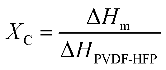
Our simple, scalable, and cost-effective approach to developing QSSE is shown schematically in Fig. 1(a), and the detailed procedure is described in the ESI.† The optical image of the flexible QSSE is shown in Fig. S1 (ESI†). The XRD patterns of the as-prepared electrolytes, P(VDF-HFP), and the nonwoven textile are shown in Fig. 1(b). The characteristic crystal peaks correspond to the crystalline phase of the PVDF-HFP at 2θ ≈ 17° (100), 19° (020), 26° (110), and 39.3° (021).26–28 The crystalline peaks of the nonwoven textile also show firm peaks, but when coated with PVDF-HFP and soaked in the liquid electrolyte to form a gel, the peak intensity decreases significantly, indicating more amorphous phases, which are eventually needed for faster ion transport. To determine the melting temperature and to correlate the crystallinity of the electrolyte with our X-ray diffraction, the thermal properties were evaluated by differential scanning calorimetry (DSC) (Fig. 1(c)). The melting temperature (Tm) and the melting enthalpy of the PVDF-HFP were found to be 141 °C and 104.7 J g−1, respectively.29 The degree of the crystalline phase (XC) was calculated using the following equation:
 | (1) |
 | ||
| Fig. 1 (a) Schematic representation of the QSSE fabrication. (b) XRD patterns of the as-developed QSSEs and nonwoven (NW) fabric. (c) DSC traces of different QSSEs; (d) TGA analysis of NaQSSEC and commercial glass fiber (GF) separator. (e) (i) optical image of nonwoven (mask); SEM images of (ii) Nonwoven (NW) fabric, (iii) surface of an NW-SPM, (iv) cross-section of NW-SPM. | ||
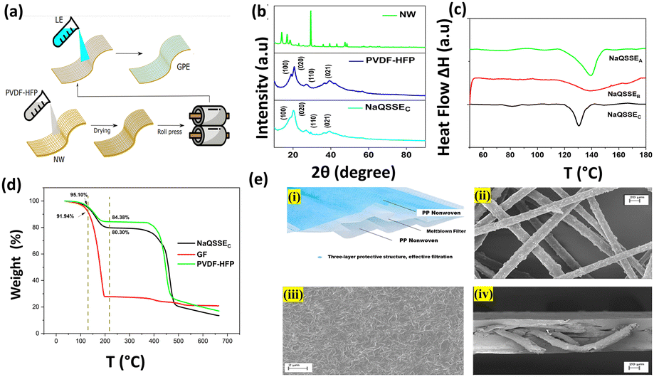
Fig. 2(a) shows the conductivity obtained from the complex impedance analysis, which shows that the highest conductivity of 1.16 × 10⁻⁴ S cm−1 was obtained for a suitable ratio of propylene carbonate/trimethyl phosphate (PC/TMP) and fluoroethylene carbonate (FEC). The electrolyte composition NaQSSEC (PC![[thin space (1/6-em)]](https://www.rsc.org/images/entities/char_2009.gif) :TMP:FEC; 85:5:10), which includes more FEC than the other two compositions (NaQSSEA (PC:TMP:FEC; 85/10/5) and NaQSSEB (PC:TMP:FEC; 85:7:8)), has been observed. NaQSSEC has a composition of PC:TMP:FEC in the ratio 85:5:10. This is because the high dielectric constant of FEC (110) leads to more substantial sodium-ion solvation power in the FEC-containing electrolytes compared to the other combinations. In Fig. 2(b), the interface stability between the developed QSSE and Na metal anodes was verified using cyclic voltammetry, in the voltage range −0.70 V to 2 V at a scan rate of 5 mV s−1. A significant redox peak was observed in the NaQSSEC electrolyte shown in Fig. 2b, attributed to sodium's plating and stripping processes at about 0 V on the stainless-steel electrode. Fig. 2b shows no significant redox reactions except for the plating/stripping of sodium from −0.70 to 2 V. The absence of anodic current indicates that the electrolyte is stable and compatible with the sodium anode. During the first cycle, sodium deposition occurs on a particular electrode surface area. This process leads to polarization to low potentials, as surface species and side reactions develop. In later cycles, as the deposited sodium acts as a nucleation center for further deposition, the deposition of sodium results in higher measured currents than in the first cycle. The anodic currents of the sodium stripping process decrease, resulting in decreasing CV peaks due to the side reactions that the sodium deposits inevitably experience. Anodic peaks are observed at higher potentials than successive cycles due to the presence of surface films on the electrodes that impede sodium ions. For high-energy-density batteries, the antioxidant ability of the electrolyte is a critical parameter. As shown in Fig. 2(c), there was a 4.77 V stability window, indicating that high-voltage cathodes could be used.
:TMP:FEC; 85:5:10), which includes more FEC than the other two compositions (NaQSSEA (PC:TMP:FEC; 85/10/5) and NaQSSEB (PC:TMP:FEC; 85:7:8)), has been observed. NaQSSEC has a composition of PC:TMP:FEC in the ratio 85:5:10. This is because the high dielectric constant of FEC (110) leads to more substantial sodium-ion solvation power in the FEC-containing electrolytes compared to the other combinations. In Fig. 2(b), the interface stability between the developed QSSE and Na metal anodes was verified using cyclic voltammetry, in the voltage range −0.70 V to 2 V at a scan rate of 5 mV s−1. A significant redox peak was observed in the NaQSSEC electrolyte shown in Fig. 2b, attributed to sodium's plating and stripping processes at about 0 V on the stainless-steel electrode. Fig. 2b shows no significant redox reactions except for the plating/stripping of sodium from −0.70 to 2 V. The absence of anodic current indicates that the electrolyte is stable and compatible with the sodium anode. During the first cycle, sodium deposition occurs on a particular electrode surface area. This process leads to polarization to low potentials, as surface species and side reactions develop. In later cycles, as the deposited sodium acts as a nucleation center for further deposition, the deposition of sodium results in higher measured currents than in the first cycle. The anodic currents of the sodium stripping process decrease, resulting in decreasing CV peaks due to the side reactions that the sodium deposits inevitably experience. Anodic peaks are observed at higher potentials than successive cycles due to the presence of surface films on the electrodes that impede sodium ions. For high-energy-density batteries, the antioxidant ability of the electrolyte is a critical parameter. As shown in Fig. 2(c), there was a 4.77 V stability window, indicating that high-voltage cathodes could be used.
 | ||
| Fig. 2 (a) Conductivity variation of different NaQSSEs at RT (30 °C); (b) cyclic voltammetry curve of the Na‖NaQSSEC‖SS cell and (c) linear sweep voltammetry at 30 °C; (d) current–time response at RT at 20 mV dc polarization voltage and Nyquist plots for symmetric cells with NaQSSEC (inset); (e) sodium plating/stripping at a current rate of 0.1 mA cm−2 of the Na‖Na symmetric cells fabricated with the NaQSSEC electrolyte, plating/stripping time of 60 minutes; (f) SEM image of sodium metal after plating/stripping. | ||
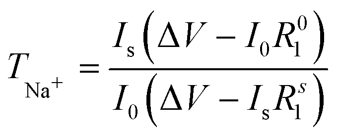
The transfer number TNa+ is the contribution of the Na+ ions to the conductivity of the electrolyte. Since Na+ is the charge carrier involved in the redox process of the battery, TNa+ is one of the key factors in the electrolyte. To calculate the transfer number (TNa+), an AC impedance and DC polarization technique was used, as shown in Fig. 2(d). For the NaQSSEC, it is found that the TNa+ is 0.68 using eqn (2),30 which is significantly higher than that of the conventional liquid electrolyte (≤0.5),
 | (2) |
The Na plating/stripping cycle tests (Na‖electrolyte‖Na) were carried out with NaQSSEC and commercial glass fiber (GF) fiber soaked in conventional electrolyte (1 M NaClO4 in EC/PC) at a constant current density of 0.1 mA cm−2, as shown in Fig. 2(e). Initially, the overpotential is ∼5.5 mV, which is increased to ∼8.7 mV, indicating a stable voltage profile over 300 h. Whereas, the overpotential for the GF-based separator increased from 345 mV to 133 mV. The Nyquist plot (inset) for both cells indicates a lower interfacial resistance with a value of 465 Ohms (Na‖NaQSSEC‖Na) compared to 877 Ohms (Na‖GF‖Na). This, in turn, results in an increase in the initial overpotential. The results confirm that NaQSSEC has good compatibility with sodium metal. Related to the above, SEM analysis of the Na metal was carried out to understand the change in the microstructure after 300 h of plating/stripping. The microstructural change (Fig. 2(f)) reveals a dense, compact, and smooth surface morphology for the NaQSSEC electrolyte where needle morphology with commercial GF-based cells is reported elsewhere.31
We tested the applicability of the electrolyte in a half-cell configuration with an NVP cathode for long-term cycling at a high charge/discharge rate of 2C as shown in Fig. 3(a). NVP was tested as the cathode material, being able to produce an extended cycle profile with liquid/gel polymer electrolytes.31,32 The cell delivers a discharge capacity of 107 mAh g−1 at a charge/discharge rate of C/10, whereas 73 mAh g−1 is obtained at a charge/discharge rate of 2C. Battery capacity is directly affected by the chemical composition and potentials of the electrodes and is proportional to the number of ions transferred. If the battery is charged with different C rates for the same voltage, the overvoltage is more significant for the faster-charged battery. Accordingly, the reduced difference in chemical potentials will result in a decrease in the number of ions transferred and a consequent reduction in capacity. In addition, charge transfer through the bilayers plays a significant role in resistance. High impedance will slow down the rate of ion transfer and increase the overvoltage (Fig. 3(c)) for the same charge rate. Interestingly, the capacity retention is 98.4% after 2500 cycles at a 2C charge/discharge rate Coulombic efficiency (CE) of 96.6%, indicating a negligible loss of capacity after long-term cycling. The EIS spectroscopy is a more realistic representation of the behavior of the electrolyte with the electrodes in a working battery. The bulk resistance and the charge transfer resistance of the Na‖NaQSSEC‖NVP cell have been measured before and after the long cycle as shown in Fig. 3(b). After cycling, the cell resistance increases from 651 Ohms to 918 Ohms. It is noted that the resistance after cycling is about 1100 Ohms, while before cycling, it is 1120 Ohms, so there is no significant change in the charge transfer resistance.
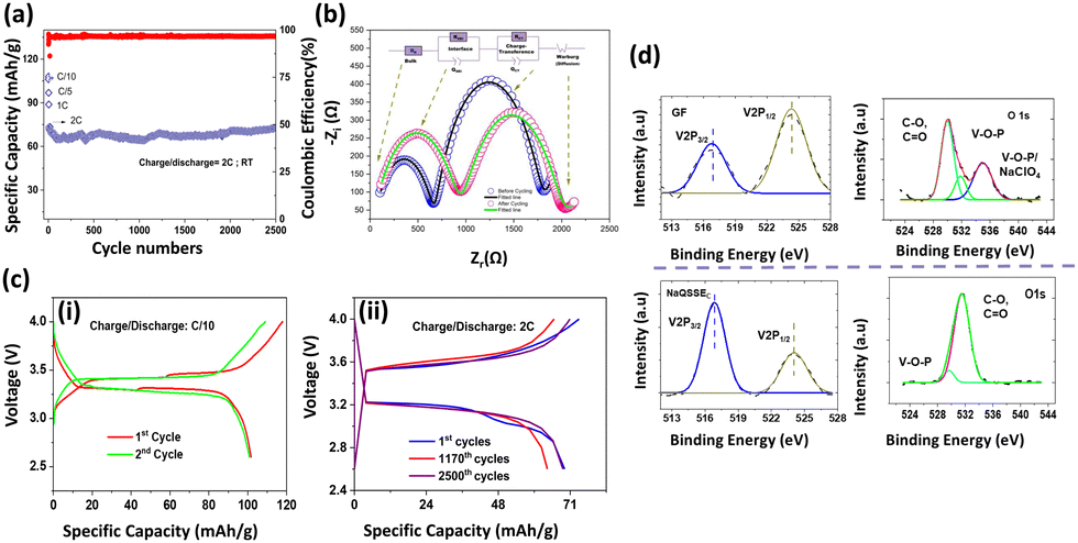 | ||
| Fig. 3 (a) Cycling stability of the Na‖NaQSSEC‖NVP cell at different current densities and long cycling at a 2C charge/discharge rate, (b) Nyquist plot of the Na‖QSSEC‖NVP cell before cycling and after cycling, (c) (i) charge/discharge curve at C/10, and (ii) at 2C rate in the cell configuration of Na‖QSSEC‖NVP at room temperature; (d) analysis of V 2p and O 1s from the XPS spectra of the NVP cathode after cycling with the NaQSSEC electrolyte and GF soaked in commercial electrolyte (1 M NaClO4 in EC/PC). | ||
The Nyquist plot fitting parameters are listed in Table S1 (ESI†). These indicate that a stable interphase has been established between the electrodes/electrolyte.33 There are no adverse reactions that could increase the interfacial resistance. The cell charge/discharge profile is shown in Fig. 3(c)-(i), (ii) for C/10 and 2C rates, respectively, in the 4.0–2.6 V range. Interestingly, the cell voltage difference is almost constant even at a 2C rate after 2500 cycles.
The V 2p and O 1s spectra of the cathode electrolyte interphase (CEI) layer are shown in Fig. 3(d). The two bands at 517.5 eV and 524.8 eV in the V 2p spectra are assigned to the V 2p3/2 and V 2p1/2 for the pristine NVP, respectively. The lower ratio of V 2p3/2 to V 2p1/2 for the NVP cathode with GF-soaked commercial electrolyte compared to the NaQSSEC-based electrolyte indicates the severe destruction of vanadium in the NVP cathode.34 Thus, a stable CEI layer on the NVP cathode is formed with the NaQSSEC-based electrolyte. For the deconvoluted O 1s spectra, it is noted that C–O, C![[double bond, length as m-dash]](https://www.rsc.org/images/entities/char_e001.gif) O, and additional V–O–P/NaClO427 signals are present for the commercial electrolyte-based NVP. In contrast, only C–O and CO signals are present for the NaQSSEC-based electrolyte-based NVP cathode.
O, and additional V–O–P/NaClO427 signals are present for the commercial electrolyte-based NVP. In contrast, only C–O and CO signals are present for the NaQSSEC-based electrolyte-based NVP cathode.
The battery's safety is paramount, especially for large-scale energy storage devices. Mainly, the polycarbonate-based electrolyte does not provide safety as it bursts into flames upon ignition. In contrast, our developed NaQSSEC is intrinsically safe as it is non-flammable upon ignition, as shown in Fig. S2 (ESI†).
In summary, a nonwoven supported quasi-solid-state electrolyte was prepared through solution casting using PVDF-HFP as the polymer matrix. The electrolyte is non-flammable with an optimized PC/TMP/FEC ratio and tested with an open flame test. The electrolyte is highly flexible and provides a conductivity of 1.16 × 10⁻⁴ S cm−1 at RT with a high transport number of 0.68. In addition, the electrolyte is compatible with Na metal and secures an electrochemical voltage window of 4.7 V. The prepared Na‖NaQSSEC‖NVP cell shows exceptional cycle stability and a capacity retention of 98.4% at a high charge/discharge rate of 2C with an initial discharge capacity of 73 mA h g−1. This study shows a cost-effective approach using a low-cost, nonwoven-supported polymer electrolyte. It is prepared with an optimal liquid electrolyte ratio to make it a non-flammable sodium metal battery operation.
Author contributions
Sayan Das: conceptualization, methodology, research, data curation, formal analysis, visualization, writing – original draft preparation, writing – reviewing and editing; Venimadhav Adyam: conceptualization, resources, supervision, draft reviewing and preparation, funding acquisition; Vilas G. Pol: draft reviewing, proof reading and preparation. All authors approved the final version of the manuscript.Conflicts of interest
The authors declare no competing financial interest.Acknowledgements
The authors are grateful to the Central Research Facility (CRF) of the Indian Institute of Technology Kharagpur, West Bengal, India, for providing the research facilities.Notes and references
- B. Luo, D. Ye and L. Wang, Adv. Sci., 2017, 4, 1700104 CrossRef.
- M. Armand and J.-M. Tarascon, Nature, 2008, 451, 652–657 CrossRef CAS PubMed.
- P. G. Bruce, S. A. Freunberger, L. J. Hardwick and J.-M. Tarascon, Nat. Mater., 2012, 11, 19–29 CrossRef CAS PubMed.
- J.-M. Tarascon and M. Armand, Nature, 2001, 414, 359–367 CrossRef CAS PubMed.
- P. K. Nayak, L. Yang, W. Brehm and P. Adelhelm, Angew. Chem., Int. Ed., 2018, 57, 102–120 CrossRef CAS PubMed.
- N. Yabuuchi, K. Kubota, M. Dahbi and S. Komaba, Chem. Rev., 2014, 114, 11636–11682 CrossRef CAS PubMed.
- J. Tang, A. D. Dysart and V. G. Pol, Curr. Opin. Chem. Eng., 2015, 9, 34–41 CrossRef.
- K. Abraham, ACS Energy Lett., 2020, 5, 3544–3547 CrossRef CAS.
- P. W. Gruber, P. A. Medina, G. A. Keoleian, S. E. Kesler, M. P. Everson and T. J. Wallington, J. Ind. Ecol., 2011, 15, 760–775 CrossRef.
- L. Zhao, T. Zhang, W. Li, T. Li, L. Zhang, X. Zhang and Z. Wang, Engineering, 2022 DOI:10.1016/j.eng.2021.08.032.
- V. S. K. Sungjemmenla, C. B. Soni, V. Kumar and Z. W. Seh, Energy Technol., 2022, 10, 2200421 CrossRef.
- Y. Jin, Y. Xu, B. Xiao, M. H. Engelhard, R. Yi, T. D. Vo, B. E. Matthews, X. Li, C. Wang, P. M. L. Le and J.-G. Zhang, Adv. Funct. Mater., 2022, 32, 2204995 CrossRef CAS.
- G. Li, X. Chen, L. Miao, J. Chen and J. Zheng, J. Power Sources, 2018, 394, 26–34 CrossRef CAS.
- Y. Suharto, Y. Lee, J.-S. Yu, W. Choi and K. J. Kim, J. Power Sources, 2018, 376, 184–190 CrossRef CAS.
- J. Wang, F. Lin, H. Jia, J. Yang, C. W. Monroe and Y. NuLi, Angew. Chem., Int. Ed., 2014, 53, 10099–10104 CrossRef CAS.
- J. Wang, Y. Yamada, K. Sodeyama, E. Watanabe, K. Takada, Y. Tateyama and A. Yamada, Nat. Energy, 2017, 3, 22–29 CrossRef.
- Y.-K. Sun, Z. Chen, H.-J. Noh, D.-J. Lee, H.-G. Jung, Y. Ren, S. Wang, C. S. Yoon, S.-T. Myung and K. Amine, Nat. Mater., 2012, 11, 942–947 CrossRef CAS PubMed.
- L. Lu, X. Han, J. Li, J. Hua and M. Ouyang, J. Power Sources, 2013, 226, 272–288 CrossRef CAS.
- G. S. Hegde and R. Sundara, Chem. Commun., 2022, 58, 8794–8797 RSC.
- S. Song, N. Hu and L. Lu, Chem. Commun., 2022, 58, 12035–12045 RSC.
- Y. Wang, S. Song, C. Xu, N. Hu, J. Molenda and L. Lu, Nano Mater. Sci., 2019, 1, 91–100 CrossRef.
- H. Sun, G. Zhu, X. Xu, M. Liao, Y.-Y. Li, M. Angell, M. Gu, Y. Zhu, W. H. Hung, J. Li, Y. Kuang, Y. Meng, M.-C. Lin, H. Peng and H. Dai, Nat. Commun., 2019, 10, 3302 CrossRef PubMed.
- Y. Yu, H. Che, X. Yang, Y. Deng, L. Li and Z.-F. Ma, Electrochem. Commun., 2020, 110, 106635 CrossRef CAS.
- J. Yang, M. Zhang, Z. Chen, X. Du, S. Huang, B. Tang, T. Dong, H. Wu, Z. Yu, J. Zhang and G. Cui, Nano Res., 2019, 12, 2230–2237 CrossRef CAS.
- Z. Zheng, X. Zhang, W. Shi, S. Liang, H. Cao, Y. Fu, H. Wang and Y. Zhu, Polymer, 2023, 269, 125751 CrossRef CAS.
- K. Karuppasamy, P. A. Reddy, G. Srinivas, A. Tewari, R. Sharma, X. S. Shajan and D. Gupta, J. Membr. Sci., 2016, 514, 350–357 CrossRef CAS.
- S. Zhang, Z. Li, Y. Guo, L. Cai, P. Manikandan, K. Zhao, Y. Li and V. G. Pol, Chem. Eng. J., 2020, 400, 125996 CrossRef CAS.
- E. Kabir, M. Khatun, L. Nasrin, M. J. Raihan and M. Rahman, J. Phys. D: Appl. Phys., 2017, 50, 163002 CrossRef.
- Z. He, Q. Cao, B. Jing, X. Wang and Y. Deng, RSC Adv., 2017, 7, 3240–3248 RSC.
- J. Evans, C. A. Vincent and P. G. Bruce, Polymer, 1987, 28, 2324–2328 CrossRef CAS.
- S. Das, S. Jana, M. Orságh, K. Bys, J. Mishra, M. Uchman and V. Adyam, ACS Appl. Energy Mater., 2023, 6, 5113–5121 CrossRef CAS.
- Y. Gao, G. Chen, X. Wang, H. Yang, Z. Wang, W. Lin, H. Xu, Y. Bai and C. Wu, ACS Appl. Mater. Interfaces, 2020, 12, 22981–22991 CrossRef CAS PubMed.
- P. Vadhva, J. Hu, M. J. Johnson, R. Stocker, M. Braglia, D. J. Brett and A. J. Rettie, ChemElectroChem, 2021, 8, 1930–1947 CrossRef CAS.
- D. Ba, Q. Gui, W. Liu, Z. Wang, Y. Li and J. Liu, Nano Energy, 2022, 94, 106918 CrossRef CAS.
Footnote |
| † Electronic supplementary information (ESI) available. See DOI: https://doi.org/10.1039/d3ya00435j |
| This journal is © The Royal Society of Chemistry 2024 |