
 Open Access Article
 This Open Access Article is licensed under a Creative Commons Attribution-Non Commercial 3.0 Unported Licence
3D printing carbon–carbon composites with multilayered architecture for enhanced multifunctional properties†
Dharneedar Ravichandran a,
Anna Dmochowskab,
Barath Sundaravadivelanc,
Varunkumar Thippannaa,
Emile Motta de Castrod,
Dhanush Patila,
Arunachalam Ramanathane,
Yuxiang Zhua,
M. Taylor Sobczake,
Amir Asadif,
Jorge Peixinhob,
Guillaume Miquelard-Garnierb and
Kenan Song
*e
a,
Anna Dmochowskab,
Barath Sundaravadivelanc,
Varunkumar Thippannaa,
Emile Motta de Castrod,
Dhanush Patila,
Arunachalam Ramanathane,
Yuxiang Zhua,
M. Taylor Sobczake,
Amir Asadif,
Jorge Peixinhob,
Guillaume Miquelard-Garnierb and
Kenan Song
*e
aSchool of Manufacturing Systems and Networks, Ira A. Fulton Schools of Engineering, Arizona State University, Mesa, AZ 85212, USA
bLaboratoire PIMM, CNRS, Arts et Métiers Institute of Technology, CNAM, HESAM Universite, 75013 Paris, France
cDepartment of Mechanical Engineering, School for Engineering of Matter, Transport, and Energy, Ira A. Fulton Schools of Engineering, Arizona State University, Tempe, AZ 85281, USA
dJ. Mike Walker ’66 Department of Mechanical Engineering, Texas A&M University, College Station, Texas 77843, USA
eSchool of Environmental, Civil, Agricultural, and Mechanical Engineering (ECAM), College of Engineering, University of Georgia, Athens, Georgia 30602, USA. E-mail: kenan.song@uga.edu
fDepartment of Engineering Technology and Industrial Distribution, Texas A&M University, College Station, Texas 77843-3367, USA
First published on 24th June 2024
Abstract
Carbon–carbon (C–C) composites are highly sought-after in aviation, automotive, and defense sectors due to their outstanding thermal and thermo-mechanical properties. These composites are highly valued for their exceptional thermal and thermo-mechanical properties, including remarkably low density and coefficient of thermal expansion, which are expected to surpass those of many alloys and other composites in the production of high-grade components. However, the current manufacturing methods for C–C composites are unable to meet market demands due to their high cost, low production speed, and labor-intensive processes, limiting their broader applications. This study presents an innovative approach by introducing a new extrusion-based 3D printing method using multiphase direct ink writing (MDIW) for C–C composite fabrication. The primary matrix utilized is a phenol-formaldehyde thermosetting resin, reinforced with silicon carbide (SiC) and graphite nanopowder (Gnp), focusing on achieving simple, scalable, and environmentally sustainable production of green parts with enhanced polymer matrix. This is followed by an inert carbonization process to obtain the final C–C composites. The research emphasizes the careful optimization of curing and rheological properties, including the use of suitable viscosity modifiers like carbon black (CB). Furthermore, the MDIW process demonstrates its capability to pattern dual nanoparticles within the composite structure in a well-ordered manner, leading to improved overall performance. Thermo-mechanical and thermo-electrical properties were thoroughly tested, showcasing the multifunctionality of the composite for diverse applications, from high-value industries like aerospace to broader uses such as heatsinks and electronic packaging.
 Kenan Song | Kenan Song serves as an Associate Professor at the University of Georgia (UGA). His research primarily focuses on the processing–structure–property relationships in advanced polymers and composites within the realm of advanced manufacturing. Dr Song specializes in the characterization, simulation, and application of polymer-based nanoparticle-filled composites, targeting sectors like energy, sustainability, health, and smart systems. His notable achievements include receiving the NSF CAREER Award (2022), the ACS PMSE Young Investigator Award (2022), the SAMPE North America Young Professionals Emerging Leadership Award (YPELA) (2022), SME 2023 Outstanding Young Manufacturing Engineer Award (2023), Humboldt Research Fellowship (2023), and the DHS New Investigator Award (NIA) (2023). |
1 Introduction
Carbon and its various allotropes, including diamonds, graphite/graphene, and buckminsterfullerene, are renowned for their exceptional physical, thermal, and electrical properties. These properties have made carbon materials crucial components in scientific, technological, and engineering fields.1,2 Among these carbon materials, carbon–carbon (C–C) composites stand out as one of the most advanced forms due to their unique composition and remarkable characteristics.3 The composition of C–C composites imparts several desirable traits that make them highly valuable for various applications. These include:4–7• Low density: C–C composites have low density, making them lightweight yet robust materials.
• Minimal thermal expansion: they exhibit minimal thermal expansion, ensuring stability and reliability under temperature variations.
• Resistance to recession: C–C composites are highly resistant to recession, maintaining their structural integrity even under harsh conditions.
• High thermal conductivity: they possess high thermal conductivity, facilitating efficient heat transfer and dissipation.
• Exceptional thermal shock resistance: C–C composites can withstand thermal shocks, making them suitable for applications involving rapid temperature changes.
• Heightened erosion resistance: they offer excellent erosion resistance, making them durable in abrasive environments.
• Chemical durability: C–C composites are chemically durable, withstanding exposure to various corrosive substances.
• Robust wear resistance: they exhibit strong wear resistance, ensuring longevity and reliability in high-wear environments.
These exceptional properties make C–C composites highly desirable for applications in extreme environmental conditions. For instance, their mechanical strength remains prominent even at extreme temperatures exceeding 1500 °C.8 Moreover, when provided with a suitable oxidative protective coating, C–C composites exhibit even greater mechanical properties compared to other composites such as carbon fiber reinforced polymers (CFRP), ceramic matrix composites (CMC), and metal matrix composites (MMC).9 The aerospace and automotive industries are among the major sectors where C–C composites find extensive use. These composites play a significant role in influencing the design and performance of high-performance vehicles, fighter jets, spacecraft, yachts, sports cars, and racing cars, including formula one vehicles.10–12 However, despite their exceptional properties and wide-ranging applications, the expensive manufacturing process of C–C composites limits their use primarily to niche applications within these industries.13
In the conventional production of C–C composites, prepregs play a central role, typically comprising a carbon-rich matrix and carbon-based reinforcements engineered to provide optimal mechanical and thermal properties to the final composite.14 These prepregs undergo a lamination process onto a preform, followed by molding to achieve the desired shape. Subsequent steps involve multiple cycles of carbonization and impregnation until the desired dimensions and morphology are achieved. Carbonization takes place in an inert atmosphere within a temperature range of 1000 to 1500 °C, leading to the denaturation of organic compounds and the formation of a solid porous carbon structure.15 Impregnation is carried out to densify the structure, utilizing techniques such as chemical vapor infiltration (CVI) or pack cementation with the same matrix under specific pressure and temperature conditions.16,17 Other processes include liquid silicon infiltration (LSI), reactive melt infiltration (RMI), or polymer infiltration and pyrolysis (PIP).18–20 For further enhancement of the modulus of elasticity and strength, the process of graphitization comes into play. This involves heat treatment at higher temperatures ranging from 2000 to 3000 °C, resulting in the creation of an ordered crystalline structure. Graphitization proves instrumental in refining atomic layouts, bringing the crystal structure closer to graphite. This refinement significantly improves lubrication, oxidation resistance, and thermal properties.21 Despite these advantages, the labor-intensive and extended manufacturing duration, and limited availability of raw materials have led to higher costs compared to other alloys and composites. Additionally, the straightforward autoclave process, molding, or forming processes have constrained the diversification of applications into various engineering domains.
The emergence of additive manufacturing (AM) technologies presents a promising avenue for revolutionizing C–C composites production. AM technologies, leveraging advancements in digital technologies like artificial intelligence and machine learning, offer unparalleled flexibility in manufacturing complex geometries with high reproducibility.22 This not only overcomes the limitations of traditional manufacturing methods but also has the potential to reduce costs and lead times significantly. Moreover, AM enables sustainable manufacturing practices by minimizing material wastage and energy consumption.23 With further advancements and integration of digital technologies, AM holds the promise of making C–C composites more accessible and affordable for a wide range of applications across various engineering domains, ushering in a new era of innovation and efficiency in composite material manufacturing.
Various AM techniques based on polymers, such as fused filament fabrication (FFF), direct ink writing (DIW), and vat polymerization, are increasingly employing carbon fiber or nanoparticle-reinforced polymeric composites as raw materials for part fabrication.24–26 In these systems, the alignment of nanoparticles, achieved through shear or external fields, has shown significant improvements in the mechanical, electrical, thermal, and other functional properties of the printed structures.27 However, a primary limitation of these polymer-based systems lies in their predominant use with thermoplastic polymers, which restricts their application in extreme conditions, particularly high temperatures.28 This limitation stems from the lower decomposition temperatures and minimal carbon yield associated with thermoplastics.29,30
For instance, in a study conducted by Dickerson et al. UV-assisted DIW was employed to 3D print lattice structures using a combination of porous ceramic and a polymethyl methacrylate (PMMA)-based triblock copolymer. While the structures exhibited high thermal resistance and flexibility post UV curing and pyrolysis, they experienced approximately a 64% shrinkage due to the ink's low carbon yield.31 In an effort to directly 3D print continuous carbon fibers (CF), the Kun Fu group introduced the rapid interlayer curing assisted (RICA) 3D printing method. This method involves guiding dry CF through localized-in-plane thermal assist (LITA) systems for epoxy impregnation, followed by a two-stage UV curing process to bind successive CF layers. Although the printed structures demonstrated commendable mechanical properties such as stiffness and strength, they exhibited poor thermal resistance beyond 400 °C due to the rapid degradation of epoxy.32 Similarly, Yi et al. demonstrated C–C composites manufacturing through selective laser sintering (SLS) using CF-coated phenolic resin. This manufacturing process involved a multistep approach of 3D printing, CVI, and heat treatment to produce C–C composites. However, challenges such as inefficiency in fiber alignment and restrictions in the aspect ratio of CF limited the attainable material properties.33
Furthermore, much of the existing research has primarily focused on manufacturing conventional nanocomposites or C–C composites using a single matrix and nanoparticle. This approach may potentially limit advancements in achieving enhanced material properties and multifunctionality. Additionally, there has been limited exploration into C–C composite manufacturing through AM techniques, warranting further research and development in this domain to unlock the full potential of AM for advanced composite materials.
This study delves into exploring the realm of 3D printing for C–C composites, leveraging a thermosetting resin and precisely engineered nanoparticles to create a multifunctional composite with exceptional thermal and electrical properties, especially at high temperatures. The 3D printing process is conducted using the innovative multiphase direct ink writing (MDIW) mechanism, which boasts a unique nozzle design with intricate internal features. This design allows for the creation of alternating layers of two immiscible polymers or nanocomposite solutions within each printing line, achieving a highly controlled and structured deposition. Our previous studies, utilizing the in-house MDIW 3D printing mechanism, have shown significant improvements in both the mechanical strength and functional properties of the printed structures, as supported by the ref. 34–36. In this specific investigation, a thermally curable thermosetting resin, namely phenol formaldehyde (PF), is chosen as the primary matrix due to its high carbon yield. This resin is combined with dispersions of silicon carbide (SiC) nanoparticles and a mixture of carbon black (CB) and graphite nanopowder (Gnp). Thorough rheological analysis is conducted to determine the optimal concentration of nanoparticles for the respective feedstocks. Additionally, differential scanning calorimetry (DSC) is utilized to pinpoint the ideal catalyst concentration for accelerated curing upon deposition. These analyses aid in achieving a precise layered patterning of nanoparticles, spanning 16 layers within each printed line, and ensuring the confinement of individual particles within each alternating layer. Following the 3D printing process, a carefully designed heat treatment process is employed to eliminate non-carbonic atoms, resulting in the fabrication of pure C–C composites. The composites are then subjected to comprehensive testing, including pore size analysis, machinability assessment, and evaluation of thermo-mechanical and thermo-electrical properties, to highlight their unique characteristics and suitability for various high-performance applications.
2 Experimental section
2.1 Materials
A resole type phenolic resin (PF), specifically Cellobond J2027L, was supplied by Bakelite Synthetics, USA. This PF resin boasts a low free formaldehyde content of less than 1%, a phenol content ranging from 6.5% to 10.5%, and a water content between 10% and 15%. The reduced formaldehyde concentration renders the resin less toxic in comparison and is primarily employed in the marine and construction industries for impregnating fiber reinforcements. This impregnation process enhances mechanical properties and imparts high-temperature resistance to the materials. The resin is thermally reactive and was stored at 0 °C to prolong the self-life.For catalyzing the thermal curing process, solid p-toluenesulfonic acid (pTSA) with a molecular weight of 190.22 g mol−1 and an assay purity ≥98.5% were procured from Millipore Sigma, USA. pTSA is a potent organic acid that is soluble in water and polar organic solvents.Reinforcement materials were also obtained: silicon carbide (SiC) β nanoparticles characterized by a cubic morphology, a particle size falling within the range of 45–65 nm, and a purity level of 99%. Additionally, graphite nanopowder (Gnp) was acquired with a particle size spanning from 400 nm to 12 μm and boasting a purity of 99.9%. SiC and Gnp were purchased from US Research Nanomaterials Inc. Carbon black (CB), utilized as a viscosity modifier, was purchased from Atlantic Equipment Engineers, Inc., USA, with particle sizes ranging from 1 to 5 μm.
Lastly, distilled water (DI-water) was generated in the laboratory using the Thermo Scientific MicroPure standard water purification system.
All the materials were used as obtained with no further modification.
2.2 Particle dispersion and feedstock formulation
Three distinct feedstock compositions were prepared, with a base of PF serving as the primary matrix material. Since the PF resin was stored at 0 °C, the resin was kept at room temperature for 20 min before further use. The control feedstock with no nanoparticle dispersion was mixed with the pTSA catalyst. In Feedstock A, SiC particles were incorporated as a dispersion. Meanwhile, feedstock B included a mixture of Gnp and CB particles. The nanoparticles were accurately weighed to the fourth decimal using a precision weighing machine and added in 50 g of the matrix. To achieve uniform dispersion, the nanoparticles were initially mixed with the matrix using a high-speed planetary mixer (FlackTek DAC 300-100 PRO), ranging in speed from 1500 to 2500 rpm, with an increment of 250 rpm every 10 s for a mixing time of 50 s. The nanoparticles were introduced into their respective feedstocks simultaneously, and the mixing process was repeated twice to ensure thorough and consistent distribution for a total mixing time of 100 s.Prior to their addition to each feedstock, pTSA was meticulously dissolved in DI water until saturation was achieved. This saturated pTSA solution was subsequently mixed into each feedstock using the high-speed planetary mixer. Similar to the nanoparticle mixing, the pTSA was also mixed at a speed of 1500 to 2500 rpm, with an increase of 250 rpm every 10 s for a total time of 50 s. The formulation and naming conventions for these feedstocks, as well as the sequence of particle and catalyst addition, are concisely summarized in Table 1.
| Matrix | Feedstock | Nanoparticle | Concentration (wt%) | pTSA conc. (wt%) | Nomenclature |
|---|---|---|---|---|---|
| a Carburized samples of PF–pTSA are denoted as PFc in text. | |||||
| PF | Benchmark | n/a | n/a | 3 | PF–pTSA |
| A | SiC | 5 | PF–SiC | ||
| B | Gnp/CB | 5/1 | PF–Gnp–CB | ||
The feedstocks were used immediately after mixing with pTSA in order to prevent premature curing. Detailed explanations of the curing conditions are explained in Section 3.2.
2.3 MDIW 3D printing setup
The Multiphase Direct Ink Writing (MDIW) 3D printing technique is a proprietary solution-based additive manufacturing process developed by the group, specifically designed for creating XY-layered composite structures using polymers or nanocomposites.37 This printer was constructed using a customizable open-source 3D printing platform, the Hyrel Hydra 16A standard. In contrast to traditional DIW 3D printing, which employs multiple nozzles for composite structure fabrication, MDIW employs a single nozzle capable of accommodating two immiscible polymer or nanocomposite solutions. This nozzle is subdivided into three sections: the spinneret, the layer multiplier, and the reducer Fig. S1.† The two immiscible feedstocks can be introduced through the spinneret's two inlets. As these feedstocks navigate the intricate internal structure, they are separated and reorganized into alternating layers of ABABAB within the layer multipliers before being deposited onto the substrate as they exit through the reducer. By increasing the number of layer multipliers, the number of alternating layers produced can be expanded exponentially by a factor of 2n+1. The rationale behind segregating SiC and Gnp–CB into distinct layers within carbon/carbon composites, as opposed to mixing the particles together, serves to optimize the material's properties and achieve desired characteristics. By layering these materials separately, precise control over their distribution is possible, ensuring a uniform dispersion throughout the composite and consistent properties. Furthermore, this approach allows for tailoring the properties of each layer to specific requirements, exploiting the distinct strengths of SiC and Gnp, such as high strength and thermal conductivity for SiC and lubrication and electrical conductivity for graphite. Additionally, layering promotes enhanced interface bonding between the matrix and reinforcement materials, improving load transfer and mechanical properties. Moreover, it prevents particle agglomeration, ensuring a homogeneous dispersion and controlled processing parameters for each layer, leading to enhanced reproducibility and consistency in the final product. Overall, layering SiC and Gnp in C–C composites offers a systematic method for designing materials with tailored properties, improved performance, and controlled manufacturing processes.One significant advantage of the MDIW mechanism, beyond its ability to generate composite structures in a single step, is its precise control over feature sizes. This control remains independent of both the dimensions of the nozzle exit and the translation step size of the motor in the XY direction. A more comprehensive understanding of MDIW 3D printing, including its construction, layer formation mechanism, and additional details, can be found in our previous publications.34–36
In this study, all the samples tested were manufactured utilizing MDIW 3D printing with the use of three-layer multipliers (n = 3), resulting in the creation of 16 alternating layers (calculated as 23+1). This study aims to showcase the capability of utilizing MDIW 3D printing to manufacture C–C composites. Moreover patterning of multiple particles can lead to higher interlayer dispersions which require better chemistry which is not in focus for this particular study. The increased number of layers allows for a more intricate and complex structure to be fabricated, which we will demonstrate with diverse particles in the future for the versatility and precision of the printing process.
2.4 Heat treatment
To produce the C–C composites, all the manufactured samples underwent a heat treatment process. In Stage I of the heat treatment process, the as-fabricated samples were subjected to various temperatures in an oven. They were subjected to temperatures of 90 °C for 12 hours, followed by 120 °C for 6 hours. This stage aimed to eliminate all residual water content and achieve complete curing of the samples.Moving on to Stage II of the heat treatment, the samples were carburized in a tube furnace under an inert atmosphere using argon. This process was designed to produce C–C composites independently of any polymeric source. The use of argon was crucial in this stage to prevent the oxidation of the composites, particularly within the temperature range of 400–600 °C. The furnace was programmed to gradually increase the temperature to 1250 °C at a rate of 1 °C min−1, with a 30 minutes isothermal hold at the end. To safeguard the samples from thermal shock, the furnace was allowed to cool down at a controlled rate of 5 °C min−1.
Characterization of each sample was performed after stages II to observe and analyze any changes in their properties.
2.5 Characterization
The rheological analysis was conducted using the Discovery Hybrid Rheometer (DHR2) from TA Instruments. A 40 mm, 2° Peltier steel cone-and-plate setup was employed with a truncation gap of 100 μm and a trim gap of 50 μm, all at room temperature. The analysis encompassed several tests:• Flow sweep measurements were taken for all the feedstocks at an increasing strain rate of 0.001–8000 s−1 to identify the change in viscosity and shear thinning character with the addition of nanoparticles. The test also served to identify viscosity similarity between the feedstocks.
• Amplitude sweep measurements were conducted at a constant frequency of 1 Hz and varying strain of 0.001–1000% to identify the linear viscoelastic region and common strain for performing a frequency sweep.
• Frequency sweep measurements were taken to identify the tan δ, storage (G′), and loss (G′′) modulus of the feedstocks at a varying frequency of 0.01–100 Hz and a constant strain of 0.5%.
• Finally, time-based flow sweep measurements were conducted to identify the change in viscosity with the addition of pTSA from 0–90 min at an interval of 30 min at an increasing strain rate of 0.001–8000 s−1.
Carbonization studies were conducted using a thermogravimetric analyzer (TGA) using the Discovery TGA 550 from TA Instruments to predict the carbon yield and temperature influence on weight change. The test was conducted on various PF resins from room temperature to 900 °C at a ramp rate of 5 °C min−1 with an isothermal dwell time of 10 min at every 100 °C in a high-temperature platinum pan for accurate measurements and observations. Sample degradation observations were also performed using the TGA to demonstrate the oxidation effect of the composite. Tests were conducted in an air and nitrogen environment for comparison from room temperature to 900 °C at a ramp rate of 10 °C min−1. The TA Trios software was used for predicting the degradation temperatures and the final sample residue.
Curing studies were conducted with a differential scanning calorimeter (DSC) using the Discovery DSC 250 from TA Instruments to identify the shift in the curing temperature with the addition of pTSA on all the feedstocks. The studies were conducted for the PF resin with varying concentrations of pTSA (0–3 wt%) from 0 to 120 °C at a ramp rate of 10 °C min−1. Similarly, the same procedure was followed to identify the curing temperature of the feedstocks with nanoparticle dispersion and 3 wt% pTSA concentration. The tests were not conducted beyond 120 °C to prevent any damage to the instrument. To identify the curing temperature of the PF resin in its native state, a temperature sweep was conducted using the DHR2 rheometer employing a 25 mm aluminum plate–plate geometry from 25–160 °C at a ramp rate of 10 °C min−1, strain of 0.5%, and a frequency of 5 Hz. A Fourier-transform infrared (FTIR) spectroscopy was performed on PF resin with and without pTSA to identify any crosslinking of the resin post-curing.
The thermal characterizations were performed using different instruments to obtain various data represented in the study. A laser flash diffusivity meter, DLF 1200 from TA Instruments was used for measuring the diffusivity value from room temperature to 1200 °C at a ramp rate of 10 °C min−1. The samples were machined into a disc of 8 mm in diameter and the thickness of the samples was ≥1.5 mm to maintain consistent measurement. The program was performed for two consecutive measurements to check for the sample's performance improvement/degradation. To calculate the thermal conductivity and diffusivity, the specific heat capacity (Cp) was measured using a differential thermal analyzer (DTA) (LABSYS EVO from Setaram), for all the samples. A continuous Cp measurement program was performed from room temperature to 1100 °C at a ramp rate of 10 °C min−1. The program was performed for all the samples including a reference sample of alumina and the Cp was calculated using an internally built function of the Setaram Calisto processing software.
A temperature-based dynamic mechanical analysis (DMA) was performed with a three-point bending setup using the DHR2 rheometer. Measurements were taken from room temperature to 500 °C or until failure, whichever comes first, since the maximum operating temperature of the machine is 500 °C. The tests were conducted at every 100 °C for a duration of 5 min with an axial strain of 0.01% and a frequency of 1 Hz. To avoid large temperature fluctuations during the measurements, the samples were soaked at the target temperature for 3 minutes as a prerequisite for the program to begin. The total sample length was 50 mm while the span length was 25 mm to avoid the sample slipping at the edges of the fixture. The test was repeated twice to check for concurrence.
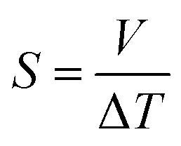
The electrical and thermo-electric measurements were taken inside a glove box to avoid oxidation of the samples using a laboratory-made setup. A hot plate with a maximum temperature of 500 °C was used as the heat source for electrical conductivity measurements from room temperature to 500 °C and the change in conductivity was measured using the two-probe method with a Keitheley DMM7510 digital multimeter. For accurate measurements, the samples were enclosed in a small chamber and soaked at the target temperature for 3 minutes before any measurements were taken. Also, the temperature at the bottom and top of the samples were measured using a probe-based digital thermometer. The Seebeck effect measurements were also taken inside a glove box with a laboratory-built setup. A soldering rod was modified to be a touch point-based heat source with a max attainable temperature of up to 450 °C. The change in voltage and temperature were measured using a digital multimeter and thermometer. All the measurements were taken at a unit distance (1 cm) between the respective probes for voltage and temperature.
Flow simulation studies were performed using SolidWorks 2023 and thermal simulation studies were performed using ANSYS Workbench 2023. Scanning electron microscopic (SEM) images were taken using a Zeiss Auriga. Gold particle coating was needed for the as-printed green samples and carburized samples were imaged as it is without any coating since the samples were conductive enough. The porosity in the carburized samples was captured vividly using the SEM. The porosity for the green samples was imaged using the backscatter electron (BSE) technique with a Thermo Fisher Scientific Teneo, a field emission scanning electron microscope (FESEM). The machine has beam deceleration capabilities, which can mitigate charging effects for non-conductive samples so the sample's porosity was analyzed without any conductive coating. BSE images show high sensitivity to differences in atomic number; the higher the atomic number, the brighter the material appears in the image. The BSE image is less affected by electric charging on the specimen surface than the secondary electron image because BSE has a high energy. Pore sizes were measured using a BET surface area and porosity analysis (Tristar II plus from Micromeritics). A minimum weight of 0.3 g was measured using a digital balance and dried at 100 °C in an inert atmosphere for 24 h using a FlowPrep before beginning the program.
3 Results and discussion
3.1 Manufacturing and layered particle patterning
The production of C–C composites comprises the manufacturing of green parts followed by high-temperature heat treatment in an inert environment. As illustrated in Fig. 1a, four distinct samples were manufactured, namely, (i) PF, (ii) PF with a homogeneous dispersion of Gnp/CB (PF–Gnp–CB), (iii) PF with a homogeneous dispersion of SiC (PF–SiC), and (iv) the multilayered sample comprising of alternating layers of both the nanocomposite feedstocks, PF–Gnp–CB and PF–SiC (PFM). Following the manufacturing process, the 3D printed samples underwent curing in an oven at 90 °C and 120 °C for 12 hours each. Subsequently, the cured samples underwent carbonization in an inert atmosphere of argon at 1250 °C, resulting in the formation of the C–C composite. | ||
| Fig. 1 Illustration of carbon–carbon (C–C) composite manufacturing with four distinct green parts: (a) PF, PF/Gnp–CB, PF/SiC, and multilayer (PF/Gnp–CB/SiC) sample fabrication followed by the carbonization process. (b) The MDIW 3D printing platform consists of (b1) ink formulation, (b2) ink loading in the syringe attached to (b3) an air cooling system, (b4) a programmable dual syringe pump, and (b5) a heating system with a heated bed and a heat gun for thermal curing. The nozzle exit (c) highlights the PF matrix encapsulating the dual particle patterning. The final C–C composite sample (d) exhibits potential thermal, electrical, thermo-mechanical, and thermo-electrical properties. | ||
The composites were manufactured using the MDIW 3D printing mechanism. This innovative technique enabled the production of a layered composite structure within the XY plane using a single nozzle. This allowed for the creation of micron-sized features within each printed line. Our in-house MDIW 3D printing process is known for its solution-based approach, where different materials or phases can be integrated seamlessly. Flow dynamics simulations illustrating the layer multiplication and microlayer formation mechanism through the MDIW nozzle, with an example of 3 multipliers in the printhead, are shown in Fig. S1.† These simulations provided valuable insights into how the XY plane layers were deposited and how the alternating layer structure of the composite was achieved. Detailed information regarding the operational platform, the nozzle, and the layer formation mechanism is explained in the Experimental section.
As illustrated in Fig. 1b, the MDIW platform was upgraded with accessories, such as the air cooling setup for the syringes and the overhead heat gun, for the efficient fabrication of the green parts to produce the multifunctional C–C composites. Alongside the 3D printing platform, the base matrix for the feedstock was a variation of commercially available PF resin, known for its high carbon yield, complemented by particle dispersions of SiC and Gnp–CB, respectively. The feedstocks were meticulously formulated through a high-speed planetary mixer (Fig. 1b1) followed by rheological tests for the printability analysis. The uniform dispersion of the nanoparticles can be seen in Fig. S2.† Subsequently, the prepared feedstocks were individually loaded into plastic syringes (Fig. 1b2) that were connected to a syringe cooling system (Fig. 1b3). The syringe cooling system was linked to a compressed air outlet while the air was maintained at 10 °C with a constant flow rate of 20 bar, which was crucial for maintaining a stable temperature for the feedstocks, prolonging their pot life. A simulation study was conducted to predict the effect of the syringe cooling system (Fig. S3†). As demonstrated in (Fig. 1b4 and b5), it was measured that the syringes can heat up to 30–35 °C due to the heat from the print bed, and the simulation predicted that the syringe can be maintained at ≈20 °C using the cooling system (Fig. S3†). This helped to improve the pot life of the feedstocks to 45 min as opposed to less than 30 min at higher temperatures.The syringe setup was then integrated into a programmable dual-head syringe pump connected to the MDIW nozzle (Fig. 1b4). The printing platform featured a heated bed, which had the capability to go up to 120 °C and a heat gun alongside the MDIW nozzle (Fig. 1b5). The syringe cooling setup was effectively used to counteract the potential rise in the syringe/feedstock temperature due to the heat flux from the print bed.
The coordination between the printer and pumps was meticulously programmed for seamless operation through G-code programming, including specifying the dimensional characteristics of the printed structures. Feedstocks were precisely extruded with the syringe pumps at a rate of 0.02 mL min−1, while the print head transition speed was set at 600 mm min−1. A layer height of 0.38 mm was maintained consistently for up to five layers along the Z-axis. The printhead configuration comprised three multipliers as an example, facilitating the production of 16 alternating layers in the XY plane (i.e., PF–SiC and PF–Gnp–CB as the alternating layer composition), as depicted in Fig. S1.† The intricacies of the MDIW process lay in the nozzle's internal design, enabling the division, rearrangement, and stitching together of feedstocks in an alternating manner. Traditionally, maintaining a laminar flow in material processing has been crucial when dealing with incompatible feedstocks to achieve uniform layer formation, as established in previous studies.34–36 However, this research introduced a novel approach where the PF resin served as the common matrix in both feedstocks, acting as a carrier medium for two distinct nanoparticles, i.e., SiC and Gnp–CB. During extrusion and deposition, the PF resin encapsulated the nanoparticles, as illustrated in Fig. 1c. Simultaneously, the nanoparticles are layered and patterned in alternating sequences Fig. S1.† Post-manufacturing, the samples underwent curing and heat treatment, following the processes elucidated earlier and depicted in Fig. 1a. These treated samples were subsequently subjected to comprehensive testing for thermo-mechanical and electrical properties, as outlined in Fig. 1d highlighting the multifunctionality of the composite.
Life cycle assessment (LCA) was conducted to evaluate the environmental impact of manufacturing multilayered C–C composites using the MDIW technique. The assessment focused on total emissions and employed an upscaling method to estimate emissions at a production scale.38 The analysis procedure involved defining system boundaries, performing inventory analysis, and upscaling the inventory for scaled production. The system boundary was confined to the manufacturing process, excluding transportation considerations.
The inventory analysis collected data on inputs and outputs throughout the manufacturing process, including raw materials, energy consumption, emissions, and waste generation. The raw material inventory was sourced directly from our production process. Initial lab-scale production indicated high greenhouse gas (GHG) emissions of 295.8 kg CO2 eq. per kg, reflecting inefficiencies due to the equipment not operating at full capacity. However, by applying an inventory scaling factor (comparable to a micro-factory), the estimated GHG emissions for scaled production were significantly reduced to 49.8 kg CO2 eq. per kg, making it comparable to traditional manufacturing methods but at a significantly reduced manufacturing time.
3.2 Material processing and curing kinetics
Widely employed as a matrix material in composite applications, PF resins are favored for their thermosetting characteristics and elevated carbon concentrations. Comprising predominantly phenol and formaldehyde molecules, the molar concentration of these constituents significantly impacts the carbon yield after carbonization. Illustrated in Fig. S4,† a range of commercially available PF resins, each characterized by distinct concentrations of phenol and formaldehyde, underwent testing for their final carbon yield through TGA, simulating the carbonization process and assessing printability. Despite subtle differences, the majority of the resins exhibited a final carbon yield surpassing 50%, with J2027L emerging as the optimal resin, featuring the best printability and a noteworthy carbon yield of 57%. Consequently, all subsequent investigations and manufacturing processes were executed utilizing the J2027L PF resin.PF resin exhibits a linear structure characterized by a gradual crosslinking rate at an elevated curing temperature determined by the molar concentrations of phenol and formaldehyde. Typically, when exposed to heat, the PF resin undergoes a polycondensation process, where the ortho or para-positions on the phenol are substituted by hydroxymethyl groups (see Fig. S5†). Sustained exposure to heat triggers the condensation reaction, leading to an increase in molar mass. The phenolic groups are interconnected by methylene chains and water (H2O) is expelled as a byproduct.39,40 Introducing an acidic catalyst with a pH ranging from 0–3 expedites the crosslinking process, facilitating a reduction in curing temperature.
As observed in Fig. S6a,† from a temperature sweep study, the J2027L PF resin utilized in this study presented a curing temperature of approximately 140 °C, necessitating a few minutes for complete curing. This posed a challenge given the MDIW printer's maximum bed temperature limit of 120 °C. At the same time, a higher curing temperature would require a longer curing time. To overcome this limitation, p-toluenesulfonic acid (pTSA) was introduced as an acidic catalyst to expedite the curing process at a lower temperature. The concentration and curing temperature should be carefully analyzed and predicted as lowering the curing temperature with a catalyst can result in an unfavorable surface topology due to vigorous exothermic reactions (Fig. S7†).
Different concentrations of pTSA were incorporated into the resin, with concentrations of 2 wt% and 3 wt% notably reducing the cure temperature, as indicated by DSC analysis in Fig. S6b and Table S1.† It is noteworthy that the addition of the catalyst accelerates the reaction but also triggers a vigorous exothermic reaction resulting in a temperature change (Fig. S7†). As a result, print parameters would have to be adjusted based on the reaction kinetics to ensure defect-free structures. Therefore a pTSA concentration of 3 wt% was chosen for the manufacturing of the green parts. A Fourier transform infrared (FTIR) spectroscopy measurements demonstrated alterations in the crosslink phenomenon due to the catalyst's presence as seen in Fig. S6c.†
A transient thermal analysis was conducted to simulate the deposition of PF resin on the print bed and study the propagation of heat and curing of the feedstock. Contour images of the simulation are depicted in Fig. S8.† While the maximum print bed temperature is set at 120 °C, the PF resin without any added catalyst requires a curing temperature of 140 °C. Therefore, the analysis focused on resin with pTSA added. The analysis revealed that with a print bed temperature of 90 °C, the first layer of deposition quickly reached the required curing temperature of 89.84 °C, as observed in Fig. S8a.† However, with an increasing number of layers, the heat conduction decreased, reaching only 85.48 °C in the final layer (Z = 5, as we had in this study). The curing of PF resin leads to pore formation due to water being a byproduct (Fig. S5†). As seen in Fig. S8b,† assuming a 50% porosity, the first layers exhibited a heat conduction of 89.67 °C, while the final layers (Z = 5, as we had in this study) showed a lower heat conduction at 72.87 °C, significantly below the required curing temperature. Thus, the heat gun, attached adjacent to the MDIW nozzle, was designed and assembled to raise the top layer resin temperature, reducing the curing time and ensuring more precise dimension control of the samples during the 3D printing process.
3.3 Rheological conditions of feedstocks
Other than the established fact that DIW-based printing processes require shear thinning behavior of the inks/feedstocks,41 two other critical criteria for achieving alternating layers in MDIW 3D printing are (i) the viscosity similarity of the feedstocks and (ii) the ability to maintain laminar flow, which are necessary to ensure the continuity and consistency of layer dimensions and compositions.34 Therefore, rheological analysis was conducted on the PF resin and its corresponding nanoparticle dispersions to determine nanoparticle concentration and its impact on curing conditions. Before the testing, the feedstock samples were prepared using the high-speed planetary mixer, following the same programming conditions as outlined in the experimental section.Illustrated in Fig. 2a, the PF resin without any catalyst (i.e., pTSA) had a viscosity of less than 1 Pa s, rendering it unsuitable for printing due to the inability to maintain continuous laminar flow or to retain the after-printing structures. The addition of pTSA, along with a 30 minutes waiting time, increased the viscosity to ≈3 Pa s, enabling the production of smooth-printed structures, as evidenced in Fig. S7.† To understand the SiC influence on rheological behaviors, the first feedstock was dispersed with a constant 5 wt% SiC and 3 wt% pTSA (i.e., for sample PF–SiC). Fig. 2a indicates no significant difference in viscosity compared to the PF + 3 wt% pTSA resin without SiC. The viscosity increasing at a lower shear rate (<0.01 s−1) followed by a decreasing trend is attributed to the deagglomeration and alignment of SiC particles along the rotating direction of the plates. The resin attains stability at 1/s before slipping at higher shear rates.
 | ||
| Fig. 2 Rheological studies showing (a) the change in viscosity with the addition of acid catalyst (pTSA) and dispersions of SiC and Gnp–CB nanoparticles. The pink stars indicate the viscosity ratio around 1 between PF–SiC and PF–Gnp–CB and (b) flow sweep highlighting the storage and loss moduli of the feedstocks. | ||
The second feedstock, initially added with 5 wt% of Gnp, did not exhibit similar viscosity or flow behavior as the first feedstock in the flow sweep test. Further addition of Gnp failed to provide the necessary viscosity-matching conditions, causing challenges for the 3D printability. However, an addition of 1 wt% CB achieved a clear match in the flow sweep (i.e., composition as indicated in Table 1), meeting the viscosity and flow conditions of the feedstocks, as observed in Fig. S9.† The viscosity ratio between PF–SiC and PF–Gnp–CB, which is represented with the pink star as η1/η2 in Fig. 2a. This ratio between feedstocks of SiC and Gnp–CB dispersions as seen with the pink line in Fig. 2a suggests a near-perfect viscosity similarity essential for the MDIW printable microlayers.
The flow sweep facilitated the determination of feedstock concentrations, settling on 3 wt% pTSA in both feedstocks, 5 wt% SiC in feedstock A, and 5 wt% Gnp in feedstock B, with 1 wt% CB serving as a viscosity modifier. Utilizing a high-speed planetary mixer, all feedstocks were meticulously prepared following the procedures outlined in the experimental section. Subsequently, the formulated feedstock underwent amplitude and frequency sweeps to identify the linear viscoelastic region (LVER) and moduli, crucial factors for determining structural integration in solution-based 3D printing like MDIW.
In the amplitude sweep, depicted in Fig. S10a,† the shaded region (i.e., black, blue, and purple region for different samples) indicates the LVER for each feedstock. The shared region among the three samples indicated the strain (i.e., in the overlapping region up to 0.5%) to be considered for the subsequent frequency sweep. The varying LVER can be attributed to the viscosity difference and the nanoparticle effect. The frequency sweep in Fig. 2b illustrates that in all three feedstocks, G′ ≫ G′′, and the addition of nanoparticles substantially increased the moduli by an order of magnitude. The tan(δ) plot in Fig. S10b† reveals that the feedstocks with nanoparticles had a tan(δ) closer to one (usually treated as the gelation point), suggesting high shape retention upon deposition.
The inclusion of pTSA not only contributed to the reduction in cure time and temperature, as discussed in the preceding section, but it also led to a shortened pot life of the feedstocks. Illustrated in Fig. 3a–c, there was a notable increase in the viscosity of the feedstocks, both with and without nanoparticles, over time, even at room temperature. This is due to the heat transfer between the surroundings and the resin. Exposure to heat at any temperature would only further diminish the pot life. Therefore, it was imperative to utilize the feedstock immediately upon preparation except in the case of pure PF resin. An intriguing observation was that the addition of pTSA in the feedstock with nanoparticle dispersion did not result in a difference in their cure temperature, as observed through the DSC analysis in Fig. S6d and Table S1.† The viscosity similarity, flow condition, and the simultaneous curing of the feedstocks would aid in preventing layer disruption post-deposition in the XY plane.
 | ||
| Fig. 3 Flow sweep indicating the change in viscosity with the addition of pTSA as a function of time at the room temperature (RT) for as-prepared feedstocks (a) PF resin, (b) PF–SiC, and (c) PF–Gnp–CB. | ||
3.4 Scalable macro structure: porosity and density along Z-axis
The preliminary experiments and analyses paved the way for the successful manufacturing of structurally integral and smoothly printed parts utilizing the MDIW printing mechanism. It is noteworthy to mention that the in-plane XY axis contained microscale layers as demonstrated in our experiments and simulations; however, the layer quality along the Z-axis needs examination regarding potential shrinkage or porosity formation during carbonization. Samples were machined to appropriate dimensions to facilitate testing their physical and mechanical properties. The high dynamic range (HDR) photographs and SEM images of the 3D printed, post-processed, and micro-machined samples are depicted in Fig. 4. | ||
| Fig. 4 MDIW printed objects with the (a1) ladder structure (5 layers along the z-axis and partially cured upon removal from the build plate), (a2) double mat structure (5 layers along the z-axis and fully cured after stage I curing); (b1) cross-sectional photograph of the ladder structure removed from the build plate with the (b2) cross-sectional SEM image showing controlled layer quality with an insert image highlighting the porosity; (c1) cross-sectional photograph of carbonized ladder structures and the (c2) cross-sectional SEM image of carbonized ladder structures with an insert image highlighting the porosity. Various machined geometries with red lines indicate the desired geometries of (d1) circular, (d2) chamfered rectangular, and (d3) diamond vs. dimensions after the carbonization. | ||
Two distinct structures were programmed and printed using the prepared feedstocks, as illustrated in Fig. 4a1 for a ladder structure and Fig. 4a2 for a double mat structure. In Fig. 4a1, the light red color denotes partial curing on the print bed, while the dark red color in Fig. 4a2 indicates complete curing following stage I curing. Moving on to the cross-sectional analysis, Fig. 4b1 and b2 depict images of a green part, while Fig. 4c1 and c2 showcase cross-sectional views of a carbonized sample. In Fig. 4b2 the inset obtained through BSE SEM imaging highlights the porosity of the printed sample post stage I curing, while Fig. 4c2, the inset highlights the porous cross-section of the sample due to the carbonization process. The images vividly capture the layer formation along the Z-axis (Z = 5), with darker shades representing the interphase between each layer. It is important to note that the initial layer height was manually set at the beginning of the printing process, with the carbonization procedure resulting in a comparatively smaller layer thickness. However, challenges arise with printing layers 4 to 5 along the Z-axis due to poor heat flux and longer cure times, deviating from the desired linearity necessary for achieving a perfect cuboidal geometry.
The carburized samples underwent BET porosity analysis to determine the pore sizes. In the PFc sample, the average pore size was found to be 3.52 nm. The pore size in PF–SiC and PF–Gnp–CB, resulted in an average size of 4.83 nm and 3.24 nm, respectively. The presence of nanoparticles can greatly influence the pore size asserting to multiple factors, such as pore filling, nucleation effect, packing factor, and surface effects due to the high surface area of nanoparticles. Comparatively, the average pore size in PFM was lower at 2 nm. This reduction in pore size in PFM can be attributed to the high packing factor of the nanoparticles within the respective layers. Additionally, it's important to consider that the gas absorption capacity of the samples significantly influences the porosity measurement using BET. The analysis of green parts revealed inconsistent results due to their low gas molecule absorbency, impacting the accuracy of the porosity measurements. The carburized samples were also measured for their true density which is the ratio between the mass of the sample to its true volume. The PF samples had a density of ≈0.86 g cm−3, while the reinforced samples of PF–SiC measured ≈0.88 g cm−3, PF–Gnp–CB measured ≈0.80 g cm−3, and the multilayer sample PFM measured ≈0.88 g cm−3.
3.5 Thermal measurements and analysis
Thermal properties are fundamental considerations in material selection and engineering design, ensuring efficient functioning and safety across various applications.42,43 In the context of C–C composites, which are renowned for their superior thermal properties,8 an array of thermal property analyses were conducted. These analyses encompassed parameters such as thermal diffusivity, conductivity, and effusivity. Additionally, the study also delved into investigating the influence of temperature on the mechanical and electrical properties of the composites. Understanding how mechanical properties such as strength, stiffness, and toughness vary with temperature is essential for designing components that can withstand thermal stresses and fluctuations. Likewise, exploring the electrical properties, including conductivity and resistivity, at different temperatures is vital for various applications. This holistic approach ensures that C–C composites can meet the requirements of diverse industries, ranging from aerospace and automotive to electronics and energy sectors, where thermal performance is paramount for operational efficiency, reliability, and safety.44–46
 | (1) |
 | (2) |
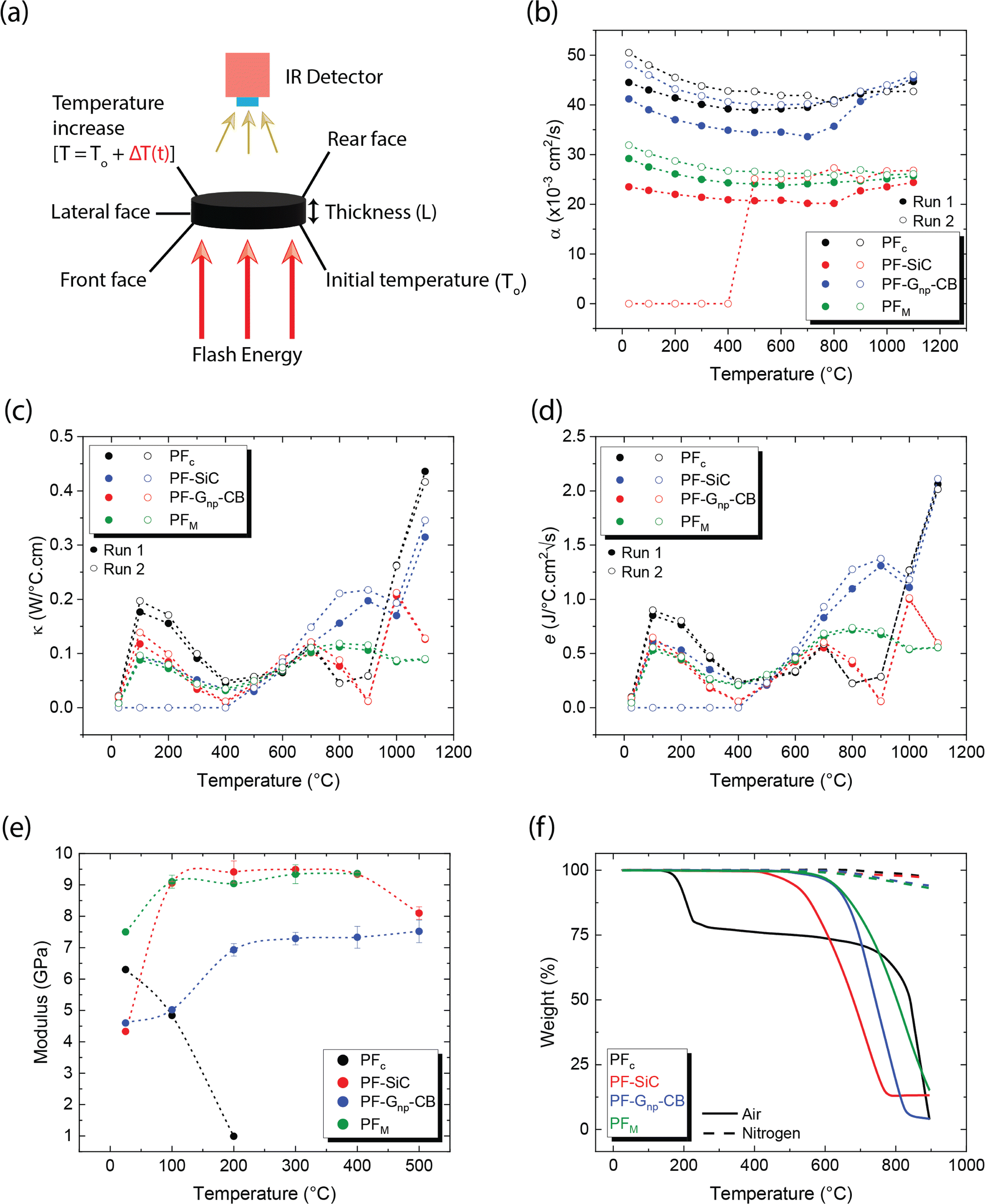 | ||
| Fig. 5 (a) Illustration highlighting the measurement technique of laser flash thermal diffusivity, (b) measured values of diffusivity of carbonized samples for two consecutive runs from room temperature to 1100 °C, (c) calculated values of thermal conductivity, (d) calculated values of effusivity, (e) DMA analysis of carbonized samples from room temperature to 500 °C or until failure in air, and (f) TGA analysis of carbonized sample showing the failure due to oxidation in air and inert (nitrogen) environment. | ||
The above equation primarily only works for homogeneous samples. Therefore, researchers performed an effective time-dependent study to measure diffusivity at any given point and any sample, given by,48
 | (3) |
Thermal conductivity measures the material's ability to conduct heat under steady-state conditions, crucial for understanding heat transfer mechanisms within the composite structure. Once the diffusivity is measured, the thermal conductivity of the specimen can be calculated as,49
| κ = αρCp | (4) |
Thermal effusivity, on the other hand, quantifies the material's ability to exchange heat with its surroundings, offering valuable information for applications involving heat dissipation or insulation. Thermal effusivity has a direct relation with conductivity and is given by the equation,50
 | (5) |
Diffusivity measurements were conducted in the out-of-plane direction for each sample in two consecutive runs, as depicted in Fig. 5b. In both runs, the PFc samples exhibited the highest diffusivity across the measured temperature range. Among the nanoparticle-reinforced samples, PF–Gnp–CB demonstrated the highest diffusivity, whereas PF–SiC displayed the lowest diffusivity, indicating lower heat mobility. An intriguing observation was made with PF–SiC, which did not register any diffusivity measurement from room temperature to 400 °C during the second run but normalized above 400 °C. The lower diffusivity values in the reinforced samples or other anomalous behaviors can be attributed to factors, such as porosity (i.e., a lower density in Gnp–CB-filled PF samples than the pure PF or PF–SiC composites) and nanoparticle arrangement within the composite. The PFM samples exhibited a diffusivity level between PF–SiC and PF–Gnp–CB, showcasing the influence of the alternative layering of nanoparticles. Moreover, the diffusivity of most samples did not change much in all cases, though the diffusivity values were higher at room temperature and 1100 °C than the intermediate temperatures. The diffusivity initially decreased up to a certain temperature (around 500–700 °C) and then increased thereafter until reaching the final temperature. Most polymers or polymer composite's diffusivity may decrease at high temperatures due to chain scission or other degradation mechanisms that disrupt the polymer matrix and hinder molecular mobility.51 Our more stable thermal diffusivity highlighted the high-temperature performance characteristics of the carbon–carbon composites. Note that the in-plane thermal measurements were challenging as the thickness in the Z-direction did not satisfy the minimum requirements of the machine.
Theoretical calculations for thermal conductivity and effusivity were performed using eqn (4) and (5), respectively, with graphical representations provided in Fig. 5c and d for two consecutive runs. These calculations are directly dependent on the specific heat capacity (Cp) of the samples. It's important to note that Cp measurements were conducted using a DTA measurement system, which involves broken or powdered samples in an alumina crucible, thereby minimizing potential influences from the directional alignment of nanoparticles. In Fig. 5c and d, no clear trend is observed in the respective measurements, and there is no significant difference between the samples. Upon closer inspection, it appears that similar to diffusivity, PFc exhibits slightly better conductivity and effusivity, followed by PF–Gnp–CB, PFM, and PF–SiC.
As depicted in Fig. 5e, PFc samples had a modulus of 6.3 GPa at room temperature but exhibited premature and rapid failure at 200 °C. This phenomenon can be attributed to the oxidation susceptibility of C–C composites in the presence of oxygen. The degradation and subsequent failure of PFc can also be linked to its thermal degradation characteristics, as evidenced by the TGA results shown in Fig. 5f and detailed in Table 2. Notably, PFc experiences approximately 25% degradation between temperatures of 122 °C and 227 °C in air, whereas no degradation is observed in an inert nitrogen atmosphere. Despite PF–Gnp–CB and PF–SiC displaying nearly identical moduli of 4.6 GPa and 4.3 GPa at room temperature respectively, PF–Gnp–CB exhibited the highest modulus in the elevated temperature range of 100 °C (5.02 GPa) to 500 °C (7.52 GPa) (Fig. 5e). Importantly, PFM demonstrated a more consistent modulus throughout the tested temperature range i.e., ≈9–9.4 GPa between 100–500 °C. Similar to PFc, all other samples exhibited failure corresponding to their respective degradation temperatures in air, as indicated by Fig. 5f and Table 2. In contrast, when subjected to an inert atmosphere devoid of oxygen, the samples demonstrated less than approximately 7% degradation even at 900 °C. The mechanical performance of C–C composites can be tailored to specific needs and applications. The properties can also be tuned by varying the nanoparticle concentration, orientation, and alignment. Table S2 and Section S1 in the ESI† gives a comprehensive comparison of thermo-mechanical properties with various combinations of materials used in the conventional manufacturing of C–C composites.
| Sample | Air | Nitrogen | |||
|---|---|---|---|---|---|
| Onset (°C) | Endset (°C) | Residue (%) | Onset (°C) | Residue (%) | |
| a PFc displayed a two-set degradation with the first one ending at 227 °C and the second at 900 °C. The residue shown in nitrogen are at 900 °C. | |||||
| PFc | 122 | 227/900 | 77.82/3.93 | 569 | 97.27 |
| PF–SiC | 375 | 765 | 13.22 | 375 | 96.75 |
| PF–Gnp–CB | 455 | 819 | 4.08 | 483 | 94.14 |
| PM | 494 | 900 | 15.22 | 402 | 93.21 |
3.6 Electric and thermo-electric characteristics
Similar to the mechanical properties, electrical measurements were also conducted as a function of the temperature effects. In conductive materials, such as metals, the decrease in electrical conductivity with temperature is attributed to the greater thermal agitation of the electrons within the material. As temperature rises, electrons gain more energy, leading to increased mobility and conductivity. However, unlike C–C composites, most metals can only withstand temperatures ranging from a few hundred to a few thousand degrees celsius. Additionally, metals typically have a high density-to-weight ratio and are often expensive.All samples in this study underwent testing for electrical conductivity across a temperature range from room temperature to 500 °C, utilizing a custom laboratory setup depicted in Fig. 6a1. The measurements were conducted using a digital multimeter, which usually measures the resistance in Ω mm and the conductivity is the reciprocal of it. Fig. 6a2 showcases the conductivity values of the samples in S mm−1 at different temperatures. PFc exhibited a lower yet consistent conductivity of approximately 0.17 S mm−1, which decreased to 0.07 S mm−1 at 500 °C. On the other hand, PF–Gnp–CB displayed the highest electrical conductivity among all samples, ranging from 0.5 S mm−1 at room temperature to 0.43 S mm−1 at 500 °C, showing consistent electrical conductivity across the temperature ranges. While PFc and PF–Gnp–CB maintained stable conductivity, PF–SiC demonstrated a sinusoidal pattern in its measurements, with higher conductivity at room temperature (0.35 S mm−1), 200 °C (0.41 S mm−1), and 400 °C (0.48 S mm−1). As stated earlier, most metals have an electrical conductivity that increases with temperature. This phenomenon occurs because higher temperatures lead to increased thermal agitation of the electrons within the material. As the temperature rises, electrons gain more energy, which allows them to move more freely through the material, resulting in higher electrical conductivity. However, in semiconductors, the electrical conductivity may decrease as temperature increases. This behavior occurs due to the presence of energy bands in the material's atomic structure. As the temperature rises, electrons are excited to higher energy levels, which can cause them to move out of the conduction band, reducing conductivity. Thus, the nonlinear relationship between electrical conductivity and temperature may occur due to complex interactions between temperature, electron mobility, and other factors within the material's structure. The electrical conductivity of PFM was notably influenced by the presence of nanoparticles at various temperatures. SiC had a significant impact on its properties at room temperature, 200 °C, and 400 °C, while Gnp–CB influenced its conductivity at other temperatures. These variations can be attributed to the arrangements of nanoparticles within the composite structures and their heat mobility.
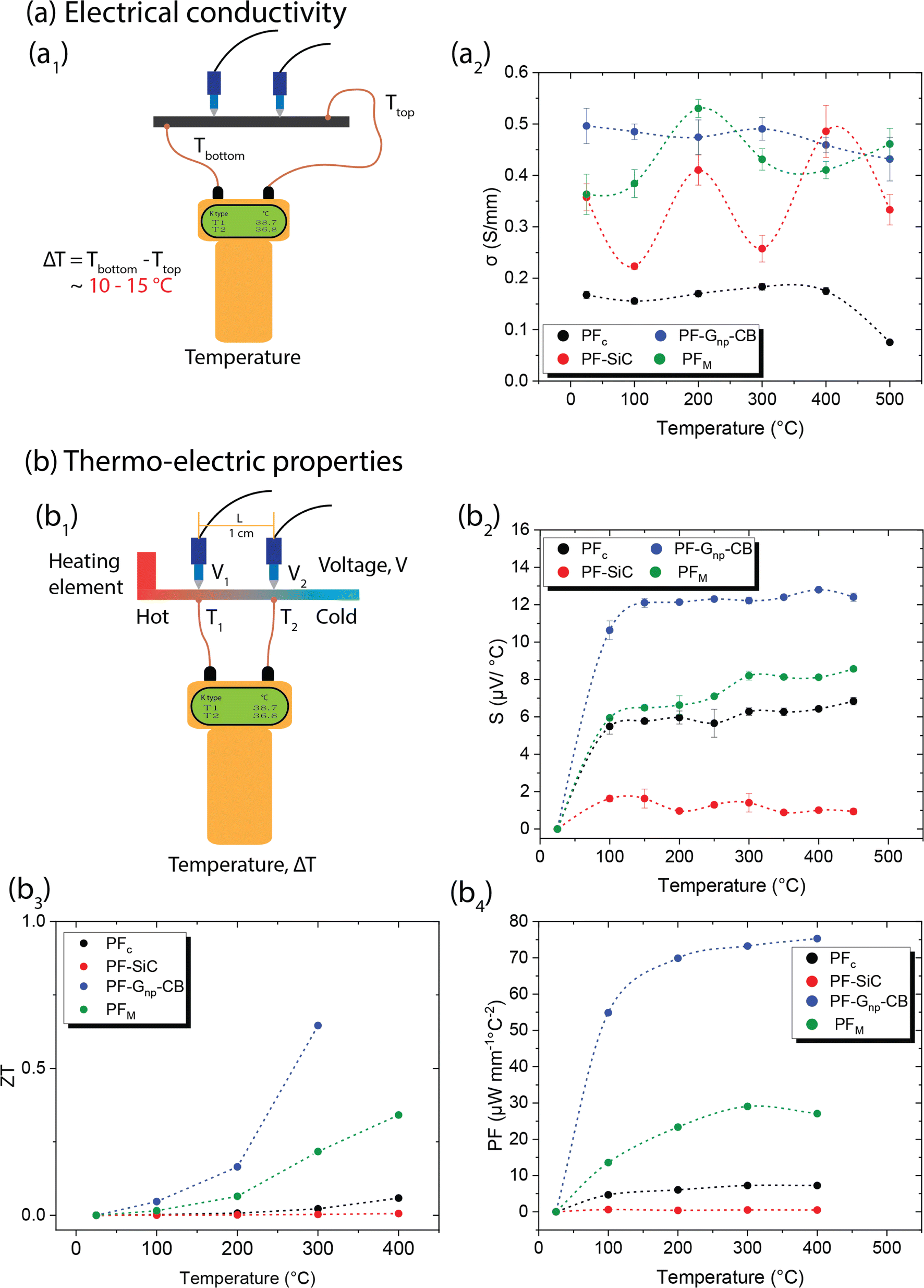 | ||
| Fig. 6 (a) Electrical conductivity measurements as a function of temperature with (a1) an illustration of the laboratory-made measurement setup and (a2) graphical representation of the measured and calculated values of electrical conduction in S mm−1 from room temperature to 500 °C. (b) Seebeck effect/thermo-electric measurements with (b1) illustration of laboratory made measurement setup, (b2) graphical representation of Seebeck effect (S) measurement with the heating element temperature reaching up to 450 °C, (b3) calculated values of figure of merit, and (b4) calculated values of power factor (PF). | ||
Several studies have emphasized the potential of C–C composites in thermo-electric characterization, which involves analyzing materials or devices based on their thermoelectric properties.11 These properties encompass the material's capacity to convert heat energy into electrical energy and vice versa, which holds significance for applications like energy harvesting, cooling systems, and thermoelectric generators.52 The characterization process typically includes measuring parameters such as the Seebeck coefficient, electrical conductivity, power factor (PF), and figure of merit (ZT value). For this study, a laboratory-made setup equipped with necessary theoretical calculations was employed to measure all these parameters, as depicted in Fig. 6b1.
The Seebeck coefficient (S) is a measure of the magnitude of the thermoelectric effect in a material. It is determined experimentally by measuring the voltage produced across a material when a temperature difference is applied, calculated by,53
 | (6) |
Following this, the ZT value and PF of the samples were calculated using the respective formulae shown below,53,54
 | (7) |
| PF = S2σ | (8) |
The ZT value is a dimensionless parameter that quantifies the overall thermoelectric performance of a material. It provides a comprehensive assessment of a material's suitability for thermoelectric applications. A higher ZT value indicates a more efficient thermoelectric material. While PF is a measure of the efficiency of a material in converting heat into electrical energy. A higher power factor indicates a more efficient conversion of heat to electricity in thermoelectric materials.
Both the ZT and PF are dependent on the Seebeck coefficient and electrical conductivity, as shown in eqn (7) and (8). In Fig. 6b3 and b4, the samples displayed a similar trend, with PF–Gnp–CB exhibiting high values of ZT and PF, while PF–SiC showed the lowest values in both cases. Despite PFc having a good Seebeck coefficient, its ZT and PF values were low due to its low electrical conductivity. The increasing ZT values with temperature of PF–Gnp–CB and PFM show the potential of these samples to be used in semiconducting applications with a proper dopant. Lastly, PFM samples performed between PF–Gnp–CB and PF–SiC, following this trend because of its combination of SiC and Gnp–CB and layered patterning.
Multifunctional C–C composites represent a relatively new area of research, as their initial development was primarily focused on achieving superior mechanical strength at high temperatures. Table S3 and Section S2† provide examples from the literature that highlight the electrical properties of conventionally manufactured C–C composites. The integration of SiC and graphene nanoplatelets (Gnp) in this study enabled us to explore and test the thermo-electric properties of these advanced materials.
4 Conclusion
This study emphasizes the utilization of innovative multi-material multiphase direct ink writing (MDIW) 3D printing techniques for manufacturing carbon–carbon (C–C) composites. Incorporating phenol formaldehyde (PF) resins as the primary matrix, reinforced with silicon carbide (SiC) and graphite nanopowder (Gnp–CB), has exhibited potential in crafting a multifunctional composite boasting desirable thermal, mechanical, and electrical properties, showcasing the versatility of C–C composites. Thorough curing investigations aided in pinpointing the optimal concentration of catalyst (pTSA) (3 wt%) for expedited resin curing at lower temperatures (90 °C), thereby accelerating the 3D printing process. Extensive rheological analyses contributed to determining the requisite nanoparticle concentrations to achieve comparable viscosities between feedstocks (5 wt% of SiC in feedstock A and 5 wt% of Gnp and 1 wt% of CB in feedstock B). Despite challenges like suboptimal interlayer dispersion of nanoparticles impacting layer formation, the characterized properties underscored the layered nanoparticle patterning's influence.The study's assessments extended to crucial parameters such as thermal diffusivity, conductivity, effusivity, mechanical strength, electrical conductivity, Seebeck coefficient, ZT value, and power factor, particularly under elevated temperatures, showcasing C–C composite's high-temperature capabilities. Among all composites and across all temperatures, PF–Gnp–CB exhibited the highest thermal and electrical conductivity, while PF–SiC demonstrated good mechanical reinforcement and thermomechanical stability. PFM samples had intermediate properties between PF–Gnp–CB and PF–SiC due to the layered architecture. While acknowledging challenges like oxidation susceptibility at elevated temperatures (400–600 °C) and the necessity for further optimization in material composition and processing, the study illuminates promising avenues for C–C composite advancements, notably in energy efficiency, high-temperature applications, and multifunctional material design.
Although C–C composites may not yet rival state-of-the-art materials across various applications, this study underscores their potential across industries, from aerospace to energy sectors, while also paving the way for future research. Enhanced material chemistry, possibly through increased reinforcement concentration, holds promise for improving properties. Incorporating a graphitization process can bolster carbon atom bonding strength, while suitable pore infiltration and oxidative coatings can enhance the C–C composite's practicality, especially in stratospheric applications where oxidation susceptibility is a concern.
Data availability
The data supporting this article have been included as part of the ESI.†Author contributions
D. R. – conceptualization, data curation, formal analysis, investigation, methodology, validation, visualization, writing – original draft, review & editing. A. D. (rheology) data curation, formal analysis, writing – review & editing. B. S./V. T./E. M. C./D. P./A. R./Y. Z. – methodology, validation, visualization, writing – review. T. S. (LCA) analysis and visualization. A. A./J. P. – supervision, resource, writing – review & editing. G. M. G – funding acquisition, supervision, resource, writing – review & editing. K. S. – conceptualization, funding acquisition, methodology, project administration, resource, supervision, writing – original draft, review & editing.Conflicts of interest
There are no conflicts to declare.Acknowledgements
We appreciate the funding from the NSF CAREER (award # 2145895), AFOSR (award # FA9550-22-1-0263), Qatar National Research Fund (Grant # NPRP14S-0317-210064), U.S. National Science Foundation EFRI (award # 2132183), CNRS International Research Project PORTO, Thomas Jefferson Fund – a program of FACE foundation launched in collaboration with the French Embassy, and the Ecole Doctorale SMI (ED 432).References
- A. Hirsch, Nat. Mater., 2010, 9, 868–871 CrossRef CAS PubMed.
- E. H. Falcao and F. Wudl, J. Chem. Technol. Biotechnol., 2007, 82, 524–531 CrossRef CAS.
- C. Scarponi, Advanced Composite Materials for Aerospace Engineering, Woodhead Publishing, 2016, pp. 385–412 Search PubMed.
- L. M. Manocha, Sadhana, 2003, 28, 349–358 CrossRef CAS.
- S. Qingliang, L. Hejun, L. Lu, L. Yunyu, F. Qiangang, L. Hongjiao and S. Qiang, Mater. Sci. Eng., A, 2016, 651, 583–589 CrossRef.
- Y. L. Li, M. Y. Shen, H. S. Su, C. L. Chiang and M. C. Yip, J. Nanomater., 2012, 2012, 11 Search PubMed.
- X. Yin, L. Han, H. Liu, N. Li, Q. Song, Q. Fu, Y. Zhang and H. Li, Adv. Funct. Mater., 2022, 32, 1–41 Search PubMed.
- R. Luo, T. Liu, J. Li, H. Zhang, Z. Chen and G. Tian, Carbon, 2004, 42, 2887–2895 CrossRef CAS.
- P. Kumar and V. K. Srivastava, Int. J. Appl. Ceram. Technol., 2016, 13, 702–710 CrossRef CAS.
- P. Chowdhury, H. Sehitoglu and R. Rateick, Carbon, 2018, 126, 382–393 CrossRef CAS.
- Y. Zhang, Q. Zhang and G. Chen, Carbon Energy, 2020, 2, 408–436 CrossRef CAS.
- M. Sreejith and R. S. Rajeev, Fiber Reinforced Composites: Constituents, Compatibility, Perspectives and Applications, 2021, pp. 821–859 Search PubMed.
- N. Shama Rao, T. G. A. Simha, K. P. Rao and G. V. V. Ravi Kumar, Carbon Composites Are Becoming Competitive And Cost Effective, Infosys Technical Report, 2018 Search PubMed.
- M. M. Gauthier, ASM Engineering Materials Handbook, 1995, 1094–1111 Search PubMed.
- G. R. Devi and K. R. Rao, Def. Sci. J., 1993, 43, 369–383 CrossRef CAS.
- S. Marinković and S. Dimitruević, Carbon, 1985, 23, 691–699 CrossRef.
- L. Zhou, Q. Fu, D. Hu, Y. Wei, M. Tong and J. Zhang, J. Eur. Ceram. Soc., 2021, 41, 194–203 CrossRef CAS.
- W. Wang, X. Bai, L. Zhang, S. Jing, C. Shen and R. He, Ceram. Int., 2022, 48, 3895–3903 CrossRef CAS.
- A. Vinci, L. Zoli, P. Galizia, M. Kütemeyer, D. Koch and D. Sciti, Composites, Part A, 2020, 137, 105973 CrossRef CAS.
- T. Lavaggi, F. Muhammed, L. Moretti, J. W. Gillespie and S. G. Advani, Composites, Part A, 2024, 181, 108156 CrossRef CAS.
- L. Zou, B. Huang, Y. Huang, Q. Huang and C. Wang, Mater. Chem. Phys., 2003, 82, 654–662 CrossRef CAS.
- W. Xu, S. Jambhulkar, Y. Zhu, D. Ravichandran, M. Kakarla, B. Vernon, D. G. Lott, J. L. Cornella, O. Shefi, G. Miquelard-Garnier, Y. Yang and K. Song, Composites, Part B, 2021, 223, 109102 CrossRef CAS.
- W. Xu, S. Jambhulkar, D. Ravichandran, Y. Zhu, M. Kakarla, Q. Nian, B. Azeredo, X. Chen, K. Jin, B. Vernon, D. G. Lott, J. L. Cornella, O. Shefi, G. Miquelard-Garnier, Y. Yang and K. Song, Small, 2021, 17, 2100817 CrossRef CAS PubMed.
- S. Jambhulkar, D. Ravichandran, V. Thippanna, D. Patil and K. Song, Adv. Compos. Hybrid Mater., 2023, 6, 93 CrossRef CAS.
- S. Jambhulkar, D. Ravichandran, Y. Zhu, V. Thippanna, A. Ramanathan, D. Patil, N. Fonseca, S. V. Thummalapalli, B. Sundaravadivelan, A. Sun, W. Xu, S. Yang, A. M. Kannan, Y. Golan, J. Lancaster, L. Chen, E. B. Joyee and K. Song, Small, 2024, 20, 2306394 CrossRef CAS PubMed.
- A. Ramanathan, V. Thippanna, A. S. Kumar, B. Sundaravadivelan, Y. Zhu, D. Ravichandran, S. Yang and K. Song, J. Polym. Sci., 2024, 62, 2670–2682 CrossRef CAS.
- D. Ravichandran, W. Xu, S. Jambhulkar, Y. Zhu, M. Kakarla, M. Bawareth and K. Song, ACS Appl. Mater. Interfaces, 2021, 13, 52274–52294 CrossRef CAS PubMed.
- J. M. Jafferson and D. Chatterjee, Mater. Today: Proc., 2021, 46, 1349–1365 CAS.
- J. Ma, J. Liu, J. Song and T. Tang, RSC Adv., 2018, 8, 2469–2476 RSC.
- G. Lee, H. G. Jang, S. Y. Cho, H.-I. Joh, D. C. Lee, J. Kim and S. Lee, Compos., Part C: Open Access, 2024, 13, 100429 CAS.
- J. J. Bowen, S. Mooraj, J. A. Goodman, S. Peng, D. P. Street, B. Roman-Manso, E. C. Davidson, K. L. Martin, L. M. Rueschhoff, S. N. Schiffres, W. Chen, J. A. Lewis and M. B. Dickerson, Mater. Today, 2022, 58, 71–79 CrossRef CAS.
- K. Deng, C. Zhang and K. K. Fu, Composites, Part B, 2023, 257, 110671 CrossRef CAS.
- X. Yi, Z. J. Tan, W. J. Yu, J. Li, B. J. Li, B. Y. Huang and J. Liao, Carbon, 2016, 96, 603–607 CrossRef CAS.
- D. Ravichandran, W. Xu, M. Kakarla, S. Jambhulkar, Y. Zhu and K. Song, Addit. Manuf., 2021, 47, 102322 CAS.
- D. Ravichandran, M. Kakarla, W. Xu, S. Jambhulkar, Y. Zhu, M. Bawareth, N. Fonseca, D. Patil and K. Song, Composites, Part B, 2022, 247, 110352 CrossRef.
- D. Ravichandran, R. J. Ahmed, R. Banerjee, M. Ilami, H. Marvi, G. Miquelard-Garnier, Y. Golan and K. Song, J. Mater. Chem. C, 2022, 10, 13762–13770 RSC.
- D. Ravichandran, W. Xu, M. Kakarla, S. Jambhulkar, Y. Zhu and K. Song, Multiphase direct ink writing for multilayered composites, US Pat., 18/170950, 2023.
- K. Kawajiri and K. Sakamoto, Sustainable Mater. Technol., 2022, 31, e00365 CrossRef CAS.
- Y. Xu, L. Guo, H. Zhang, H. Zhai and H. Ren, RSC Adv., 2019, 9, 28924–28935 RSC.
- K. Tang, A. Zhang, T. Ge, X. Liu, X. Tang and Y. Li, Mater. Today Commun., 2021, 26, 101879 CrossRef CAS.
- J. A. Lewis, Adv. Funct. Mater., 2006, 16, 2193–2204 CrossRef CAS.
- G. Grimvall, Thermophysical Properties of Materials, Elsevier, 1999 Search PubMed.
- A. A. Balandin, Nat. Mater., 2011, 10, 569–581 CrossRef CAS PubMed.
- A. K. Sehgal, C. Juneja, J. Singh and S. Kalsi, Mater. Today: Proc., 2022, 48, 1609–1613 CAS.
- M. Sang, J. Shin, K. Kim and K. J. Yu, Nanomaterials, 2019, 9, 374 CrossRef CAS PubMed.
- S. Choudhary, J. Haloi, M. K. Sain, P. Saraswat and V. Kumar, Mater. Today: Proc., 2023, 1–8 CAS.
- M. J. Patrick, PhD thesis, North Carolina Agricultural and Technical State University, 2013 Search PubMed.
- E. P. Roth, R. D. Watson, M. Moss and W. D. Drotning, Thermophysical Properties of Advanced Carbon Materials for Tokamak Limiters, Sandia National Laboratories, technical report, 1989 Search PubMed.
- B. Weidenfeller, M. Höfer and F. R. Schilling, Composites, Part A, 2004, 35, 423–429 CrossRef.
- R. C. Dante, Handbook of Friction Materials and Their Applications, Woodhead Publishing, Boston, 2016, pp. 123–134 Search PubMed.
- M. Horikx, J. Polym. Sci., 1956, 19, 445–454 CrossRef CAS.
- L. Yang, Z. G. Chen, M. S. Dargusch and J. Zou, Adv. Energy Mater., 2018, 8, 1701797 CrossRef.
- J. O. Morales-Ferreiro, D. E. Diaz-Droguett, D. Celentano and T. Luo, Front. Mech. Eng., 2017, 3, 15 CrossRef.
- G. J. Snyder and A. H. Snyder, Energy Environ. Sci., 2017, 10, 2280–2283 RSC.
Footnote |
| † Electronic supplementary information (ESI) available. See DOI: https://doi.org/10.1039/d4ta02267j |
| This journal is © The Royal Society of Chemistry 2024 |