
 Open Access Article
 This Open Access Article is licensed under a
 Creative Commons Attribution 3.0 Unported Licence
pH-responsive and antibacterial PANI-PEDOT:PSS fibres for wearable applications†
Rachel E.
Smith
a,
Stella
Totti
a,
Daniel
Reid
a,
Suzanne M.
Hingley-Wilson
b,
Eirini
Velliou
 a,
Paola
Campagnolo
b,
Neil I.
Ward
a,
John R.
Varcoe
a and
Carol
Crean
*a
a,
Paola
Campagnolo
b,
Neil I.
Ward
a,
John R.
Varcoe
a and
Carol
Crean
*a
aSchool of Chemistry and Chemical Engineering, University of Surrey, Guildford, GU2 7XH, UK. E-mail: c.crean@surrey.ac.uk
bDepartment of Microbial Sciences, University of Surrey, Guildford, GU2 7XH, UK
First published on 30th January 2024
Abstract
With the emergence of wearable electronics for health and the prevalence of chronic wounds, there is demand for an effective wearable pH sensor. A simple method of solvent treating wet-spun poly(3,4-ethylenedioxythiophene)-poly(styrenesulfonate) (PEDOT:PSS) fibres proved effective in the development of highly conductive fibre substrates. With an optimised polyaniline coating, these fibres displayed a Nernstian response to changes in pH in the solid-state vs. a fabricated pseudoreference electrode across a wide pH range of 3.0 to 9.0. In addition, these biocompatible fibre electrodes displayed antibacterial properties. The fibre electrodes offer significant opportunities for future wearable textile-based sensors as well as the realisation of a real-time, on-body pH sensing device for monitoring skin and wound healing.
1. Introduction
Biochemical reactions in the body are hugely influenced by pH, therefore wearable pH sensors could have a pivotal role to play in healthcare and personalised medicine. The information provided could help to track changes in health status, diagnose diseases, and manage treatment. Electrochemical pH sensors are beneficial due to the ease of miniaturization of the associated electronics.1 This is best exemplified by wearable electrochemical blood glucose meters, which successfully facilitate diabetes management. Wearable pH sensors can be used to monitor health conditions such as skin disease, and for environmental hazard monitoring, in addition to measuring sports performance.1 In healthcare, wound care is a significant burden, with chronic wounds causing an estimated annual cost of £5.3 billion in the UK alone.2 Chronic wounds have a maximum of pH 9.0 and healthy, unwounded skin has a minimum of pH 4.0, (with sweat ranging from 4.5 to 7.0), therefore the pH range needed for analysis is pH 4.0 to 9.0.3,4Current examples of pH sensors have primarily focused on materials such as hydrogen ionophores, metal oxides and polyaniline.5 These materials were used to facilitate wearable sensing, with small form and flexibility allowing easier integration into devices in contrast to the traditional glass pH electrode. Hydrogen ionophores in a solid-state ion selective electrode have been used for pH sensing in a wearable format by Andrade et al. and Niu et al. Andrade et al. coated a cotton thread with carbon nanotubes followed by a hydrogen ion sensing membrane, which was flexible with an excellent pH response.6 Niu's group used a similar strategy with a stretchable gold fibre electrode as the solid-state electrode, which had minor pH variation (−59.2 to −57.4 mV pH−1) upon stretching between 0 and 200% strain.7
The development of micro–nano structures in metal oxides has enabled flexible and mechanically robust electrodes with good electrochemical response to pH. Iridium oxide (IrOx) exhibits a wide range pH response and is the most commonly reported in flexible sensing applications, however, is expensive.5 WO3–based potentiometric pH sensors are an attractive alternative but need further research to address the sub-Nernstian behaviour and slow response time.5
Polyaniline (PANI) lends itself to wearable pH analysis because of its pH-sensitivity, good electrical conductivity and biocompatibility.8 Guinovart et al. reported a screen–printed PANI electrode on a bandage that could detect pH of a wound with a sensitivity of −58.5 mV pH−1, over the range of pH 5.5–8.0 with an RSD of 1.2%.9 Wang et al. recently reported a stretchable gold coated styrene-ethylene/butylene-styrene fibre with an electropolymerized PANI layer for pH sensing. This fibre electrode showed a Nernstian response over the pH range of 4.0–8.0 even when stretched at 100% strain.10
Our previous work evaluated fibres made from different suppliers of the conducting polymer poly(3,4-ethylenedioxythiphene)-poly(styrenesulfonate) (PEDOT:PSS) and how solvent treatment (both solvent and time) affected the fibres and their properties (size, electrical properties, mechanical properties, XPS studies, electrochemical surface area).11 PEDOT:PSS can be easily spun into fibres by the industrially-scalable technique of wet-spinning. This helped us to determine that DMSO was superior to the other two solvent treatments because it improved the electrical properties of the fibres while maintaining and even slightly improving their mechanical properties.
In this study, we significantly extend that work by optimising the electrochemical deposition of PANI onto wet-spun PEDOT:PSS fibres via three different electropolymerisation methods, to allow for the real-time monitoring of pH. Key variables were optimised and the resulting fibre was used for small volume analysis. We further show that an optimised wearable pH sensor, consisting of PANI-PEDOT:PSS fibres vs. a wearable Ag/AgCl pseudoreference electrode, exhibits a Nernstian response over pH 3.0 to 9.0, even in pH-adjusted sweat matrices and human plasma. Microbiological and biocompatibility testing revealed that this biocompatible composite fibre also exhibited significant antibacterial properties.
2. Experimental
2.1. Materials
Aqueous PEDOT:PSS dispersion (Clevios PH 1000, 1 wt%) was procured from Heraeus (Germany). The following analytical grade chemicals were purchased from Sigma Aldrich (UK): dimethyl sulfoxide (DMSO), methanol, boric acid, phosphoric acid, acetic acid, sodium chloride, sodium hydroxide, ammonium chloride, magnesium chloride, pyruvic acid, glucose, urea, calcium carbonate, potassium nitrate, sodium nitrate, polyvinyl butyral (PVB) and Escherichia coli and nutrient broth. Human plasma mixed pool product was purchased from TCS Biosciences Ltd (Buckingham UK). The human keratinocytes (HaCaT) cells were purchased from CLS Cell Lines Service. Alamar Blue reagent was procured from ThermoFisher. The gauze fabric (100% cotton) was purchased from a local pharmacy. Ag/AgCl paste (C2130809D5) was obtained from Sun Chemicals® (Parsippany, NJ). An E. coli wild-type strain expressing yellow fluorescent protein (YFP; Balaban et al.12) was used in these experiments. Artificial sweat matrix was prepared containing 6 mM KCl, 0.08 mM MgCl2, 0.18 mM pyruvic acid, 0.17 mM glucose, 5 mM NH4Cl and 10 mM urea.2.2. Instrumentation
All electrical resistance analyses were performed by mounting the fibres with silver paint on four electrical pins separated by 2 mm spaces. A constant current of 10 μA was applied across the two outer pins and the resulting voltage across the two inner pins was measured using a Keithley 2001 multimeter. Raman spectroscopy was performed on an inVia confocal Raman microscope (532 nm excitation, Renishaw UK). Scanning electron microscopy (SEM) images were obtained using a JEOL USA JSM-7100F analytical field emission electron microscope at 5.0 keV. Dynamic mechanical analysis (DMA) was performed using a TA Instruments Q800. Analysis was performed using 0.0001 N preload force, and an appropriate rate of force increase, chosen to provide sufficient data points for each sample. Fluorescence intensity measurements during the antibacterial tests were performed on an A1+ confocal Nikon microscope (Nikon A1M on Eclipse Ti-E). An EDAQ potentiostat EA163 and EDAQ e-corder 410 was used for the PANI electropolymerisation and potentiometric measurements.2.3. Fabrication of conductive fibres
The PEDOT:PSS fibres were produced using the same wet-spinning method as Okuzaki et al.13 Briefly, PEDOT:PSS ink (2 wt%) was prepared from an aqueous stock dispersion (1 wt%) via evaporation at 50 °C. The PEDOT:PSS ink was injected via syringe (using either a 16 G or 18 G needle with inner diameters of 1.19 mm and 0.18 mm respectively) into a rotating solution (10 rpm) of propan-2-ol and acetone (1![[thin space (1/6-em)]](https://www.rsc.org/images/entities/char_2009.gif) :1) at the rate of 0.75 or 0.05 mL h−1 for diameter 75 μm and 25 μm fibres, respectively.
:1) at the rate of 0.75 or 0.05 mL h−1 for diameter 75 μm and 25 μm fibres, respectively.
The resulting wet-spun fibres were either untreated (no solvent treatment post wet-spinning) or treated with DMSO. For DMSO treatment, the fibres were immersed in neat DMSO for 5 min and then dried for 30 min at 140 °C. DMSO-treated fibres with a diameter of 20 μm were selected as the base substrate for the final pH sensor (vide infra).
2.4. Fabrication and testing of the pH-sensitive fibre electrodes
To construct pH-sensitive fibres, polyaniline (PANI) was coated onto the fibre electrodes via cyclic voltammetry (CV), galvanostatic, and potentiostatic polymerisation in a solution of aniline (0.1 M) in HNO3 (1.0 M) at room temperature. Solutions were degassed with N2 before use. For polymerisation by CV, the potential was cycled from −0.2 to +1.0 V vs. Ag/AgCl (3 M KCl internal solution, BASi, UK) at 100 mV s−1. For galvanostatic polymerisation, a current density of 2 mA cm−2 was applied, as used by Yang et al.14 Potentiostatic polymerisation, was carried out at 0.8 V vs. Ag/AgCl.15 CV cycles were varied between 5 and 20, while deposition times for galvanostatic and potentiostatic deposition were varied from 3 to 10 min to optimise the PANI coating. PANI coated fibres were subsequently rinsed with deionised water and air dried prior to further use. The PEDOT:PSS fibre (1 cm length) was employed as the working electrode with a Ag/AgCl reference electrode and a Pt mesh counter electrode (1 cm2 geometric area).Potentiometry was used for pH analysis and the potential of the PANI-PEDOT:PSS fibre electrodes (1 cm length) was measured against a Ag/AgCl double junction reference electrode (3 M NaCl internal solution, Alvatek, UK). Britton–Robinson pH buffered solutions were made from a mixture of 0.04 M boric acid, 0.04 M phosphoric acid, 0.04 M acetic acid and were adjusted to the desired pH (2.0 to 12.0) with 0.2 M NaOH.
The interference studies were performed using the method reported by Nyein et al.: interference solutions of 1 mM NH4Cl, 1 mM MgCl2, 1 mM CaCO3, 8 mM KNO3 and 20 mM NaNO3 were subsequently added to a Britton–Robinson buffer solution of pH 4.16 With the addition of an interference solution, there was a 20 s waiting period and then the voltage was measured. At the end of the study, the solution was changed to a buffer solution of pH 5 and the voltage was measured again.
2.5. Fabrication and testing of the wearable pseudoreference electrodes
For the quasi-real-world low volume pH analysis, a wearable Ag/AgCl pseudoreference electrode was fabricated. Two methods of constructing a Ag/AgCl pseudoreference electrode were used. In method 1, only a Ag/AgCl-ink was coated onto the substrate surface. In method 2, the already Ag/AgCl-coated substrate was then dip-coated with a reference ion-selective membrane (RF-ISM) as detailed below. Gauze fabric and carbon fibres (CF) were both investigated as substrates.For low volume analysis, a planar side by side two-electrode set-up was used with the potential of the PANI-PEDOT:PSS fibres electrodes recorded against the fabricated Ag/AgCl pseudoreference electrode (Ag/AgCl-gauze were selected as the reference electrode for the final pH sensor). During analysis, a 200.0 μL drop of pH buffer (3.0 to 9.0) was placed between the two electrodes covering both electrodes. The drop was removed with absorbent tissue between measurements.
2.6. Antibacterial testing of final sensors
The antibacterial testing was performed using the same method as Smith et al.18E.coli cells were picked from a Luria Bertani agar plate, then grown in liquid culture with agitation at 300 rpm for 16 h at 37 °C. 300 μm lengths of thin DMSO PEDOT:PSS fibres (bare and PANI-coated) and 0.09 cm2 areas of gauze (bare and Ag/AgCl-coated) were cut with a sterilised scalpel blade and sterilised by dipping in ethanol. The bacterial cells were then aliquoted (300 μL) at a final cell density of 1.28 × 10⁸ cells mL−1 into wells containing the sensors. The 96-well plate was shaken at 150 rpm at 37 °C for 4 h. Subsequently, each “biofouled” fibre was transferred to a clean well (containing no solution or bacilli). Images were captured across a fixed area of 0.217 mm2 and the mean intensity of fluorescence was measured with a Nikon confocal microscope using the fluorescein isothiocyanate (FITC) filter at 488 nm and using a 40× air objective lens (NA = 0.96).2.7. Cell viability studies of final sensors
The biocompatibility testing was performed using the same method as Smith et al.18 500 μm lengths of thin, DMSO-treated PEDOT:PSS fibres (bare and PANI-coated) and 0.05 cm2 area of Ag/AgCl-gauze (0.5 cm by 0.1 cm) were dipped in ethanol for 3 h, air-dried and then sterilised for 10 min in a UV/ozone generator (BioForce Nanosciences). The human keratinocyte cells HaCaT (300493, CLS, Germany) were seeded at a density of 104 cells per well into 96-well plate and allowed to adhere on the well surface for 24 h at 37 °C in a humidified atmosphere containing 5% CO2 and 20% O2. After this period, the sensors were then placed on top of the cells. The cell viability was assessed using the Alamar Blue® assay (Thermofisher Scientific, UK). This bioassay incorporated a redox indicator resulting in colour change of the culture medium according to cell metabolism. The toxicity of this assay is negligible, so it can be used multiple times on the same samples. The samples were incubated with the Alamar blue dye diluted in the cell culture medium according to the manufacturer's instructions for 1.5 h at different culture time points: 1, 3 and 5 d post fibre administration on the cells. The absorbance was measured with a spectrophotometer (Synergy, BioTek, VT, USA) at 570 nm and at 600 nm, as a reference wavelength. Finally, the cell viability was calculated using the dye molar extinction coefficients and appropriate absorbance equations provided by the manufacturer.Statistical analysis was performed from N = 3 independent experiments with at least a triplicate (n = 3) per experiment. Error bars represent sample standard deviation. Analysis of variance (Two way ANOVA) was performed using GraphPad Prism® software with a p-value threshold 0.05 to evaluate whether there was a statistical difference between the experimental conditions.
3. Results and discussion
3.1. Development of conductive fibres
A major challenge with using PEDOT is its insolubility in water, therefore, PSS is used as a dopant to form water-dispersible PEDOT:PSS. The addition of insulating PSS, however, has a detrimental effect on the electronic conductivity. PEDOT can have conductivities above 1500 S cm−1, whereas, the water-soluble copolymer PEDOT:PSS has a conductivity below 1 S cm−1, too low to be used for electropolymerisation or sensing.19 Previous studies have reported that treating PEDOT:PSS with solvents, for example, trifluoromethanesulfonic acid, sulfuric acid and DMSO can increase the conductivity because of the removal of insulating PSS and re-ordering of the polymer chains.20,21 For example, Kara et al. observed that the conductivity of electrospun PEDOT:PSS nanofibres increased 15-fold with the addition of DMSO to the spinning solution.22We previously examined two different suppliers of PEDOT:PSS, different fibre spinning conditions and solvent treatments and found that a combination of Clevios PEDOT:PSS and DMSO solvent treatment gave the best improvement in electrical conductivity with no detriment to the mechanical properties.11 Further improvements in mechanical properties can be achieved using fibre drawing methods post-spinning.23 In this study, two different fibre dimensions were produced: thick and thin fibres with an average diameter of 70–80 μm and 20–25 μm diameter, respectively. No significant change in conductivity was observed for the different fibre diameters with 125 ± 11 S cm−1 and 122 ± 18 S cm−1 for thick and thin fibres (no solvent treatment), respectively. After DMSO treatment, the conductivity of thin fibres significantly increased, whereas the conductivity of the thick fibres increased to a lesser degree (Table 1). DMSO treatment removes the PSS on the fibres’ surfaces. Proportionally, thin fibres contain less PSS than thick fibres. Therefore, removal of surface PSS by DMSO will have a greater net effect on the conductivity of the thin DMSO-treated fibres compared to the thick DMSO-treated fibres. The most conductive fibre produced was the thin PEDOT:PSS fibre with DMSO treatment, achieving a notable conductivity of 802 ± 122 S cm−1.
| PEDOT:PSS fibre type | Diameter/μm | Conductivity/S cm−1 | pH response/mV pH−1 |
|---|---|---|---|
| Thick (no treatment) | 75 ± 13 | 125 ± 11 | −45 ± 4 |
| Thick (DMSO treatment) | 77 ± 7 | 323 ± 35 | −38 ± 7 |
| Thin (no treatment) | 21 ± 2 | 122 ± 18 | −49 ± 5 |
| Thin (DMSO treatment) | 21 ± 2 | 802 ± 122 | −56 ± 7 |
![[double bond, length as m-dash]](https://www.rsc.org/images/entities/char_e001.gif) Cβ stretching vibrations and aromatic chain vibrations of PSS, respectively (Table 2 and Fig. S2, ESI†).24 The spectra of the wet-spun PEDOT:PSS fibres showed a change post-DMSO treatment. The peak observed at 1435 cm−1 in the untreated 25 μm fibres shifted to 1428 cm−1 following solvent treatment (the spectral resolution of the Raman spectrometer was <1.0 cm−1); this peak is attributed to symmetric stretching of the five-membered thiophene ring, which can be present as either the benzoid (CαCβ) or quinoid (Cα–Cβ) resonant structure depending on the oxidation state and the level of doping.25 This shift is considerably less prominent in the thick fibres from 1436 cm−1 (untreated) to 1433 cm−1 on solvent post-treated. When the polymer is solvent treated, there is a conformational change of the PEDOT chains from a coiled benzoid structure to a more linear structure. This enhances the mobility of the charge carriers in the PEDOT:PSS, explaining the observed increase in conductivity with DMSO treatment.26
Cβ stretching vibrations and aromatic chain vibrations of PSS, respectively (Table 2 and Fig. S2, ESI†).24 The spectra of the wet-spun PEDOT:PSS fibres showed a change post-DMSO treatment. The peak observed at 1435 cm−1 in the untreated 25 μm fibres shifted to 1428 cm−1 following solvent treatment (the spectral resolution of the Raman spectrometer was <1.0 cm−1); this peak is attributed to symmetric stretching of the five-membered thiophene ring, which can be present as either the benzoid (CαCβ) or quinoid (Cα–Cβ) resonant structure depending on the oxidation state and the level of doping.25 This shift is considerably less prominent in the thick fibres from 1436 cm−1 (untreated) to 1433 cm−1 on solvent post-treated. When the polymer is solvent treated, there is a conformational change of the PEDOT chains from a coiled benzoid structure to a more linear structure. This enhances the mobility of the charge carriers in the PEDOT:PSS, explaining the observed increase in conductivity with DMSO treatment.26
| 75 μm (no DMSO) | 75 μm (DMSO) | 25 μm (no DMSO) | 25 μm (DMSO) | Assignments |
|---|---|---|---|---|
| Raman shift/cm−1 | ||||
| 1257 | 1257 | 1257 | 1257 | Cα–Cα inter-ring stretching |
| 1367 | 1367 | 1367 | 1367 | Cβ–Cβ stretching |
| 1436 | 1433 | 1435 | 1428 | CαCβ stretching |
| 1507 | 1507 | 1507 | 1507 | Asymmetric CαCβ stretching |
| 1566 | 1566 | 1566 | 1566 | Aromatic chain PSS |
3.2. Development of pH-sensitive fibres
Different electropolymerisation approaches were trialled to find the ideal conditions for pH sensing PEDOT:PSS fibres. Experimental methods for electrodepositing PANI include cyclic voltammetry (CV), potentiostatic and galvanostatic techniques. Following PANI deposition via CV onto the four types of PEDOT:PSS fibres, the pH sensitivity was assessed against a double-junction Ag/AgCl electrode (Column 3 in Table 1). The thick PEDOT:PSS fibres, without and with the solvent treatment, gave the poorest pH sensitivity with a slope of −45 ± 4 and −38 ± 7 mV pH−1, respectively. As established by the conductivity values (Table 1), the thick fibres have a higher ratio of hydrophilic PSS to PEDOT, which leads to more water being absorbed and more fibre swelling during pH analysis that affects the resistance of the electrode and results in a poor quality PANI deposition.27 The thin fibres without solvent treatment showed improved pH sensitivities (−49 ± 5 mV pH−1). The best pH response was achieved by the thin fibres with DMSO treatment with a Nernstian response (−56 ± 7 mV pH−1). As this DMSO-treated thin PEDOT:PSS fibre achieved the highest conductivity and a Nernstian response when PANI coated, it was down-selected for further optimisation of the PANI coating.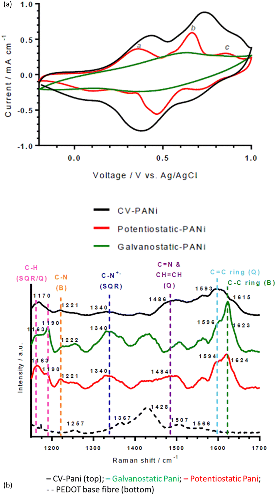 | ||
| Fig. 1 (a) Cyclic voltammograms and (b) Raman spectra of wet-spun thin, DMSO-treated PEDOT:PSS fibres PANI-coated via cyclic voltammetry, potentiostatic and galvanostatic techniques. | ||
The middle peak (b in Fig. 1a, Epa at 0.66 V (potentiostatic), 0.74 V (CV) and 0.63 (galvanostatic) vs. Ag/AgCl) is normally due to the redox couple of benzoquinone/hydroquinone, which is a degradation product of PANI.29 However, characteristic Raman peaks for benzoquinone are absent (1644 and 1651 cm−1 for CC and CO bands, respectively). Thus, the peak may be due to the dimer intermediate, p-aminodiphenylamine, which is found at ∼0.70 V vs. Ag/AgCl and results from head-to-tail coupling of aniline. It will contribute to the intensity of Raman bands attributed to C–C ring stretching (∼1620 cm−1) and C–N stretching (∼1220 cm−1) in the Raman spectra of the PANI-deposited fibres (Fig. 1(b)). In contrast to the other deposition types, the galvanostatic-deposited PANI fibre has one broad, ill-defined middle peak centred at 0.63 V vs. Ag/AgCl (that may be obscuring the other conventional PANI redox peaks).
Interestingly, variations in redox potentials and Raman spectra were observed between the three deposition techniques. CV regularly cycles the electrode potential throughout the deposition (−0.2 V to 1.0 V), cycling the electropolymerised PANI from its non-conducting forms (leucoemeraldine and pernigraniline salts) to its conducing form (emeraldine base, between 0.8 and 1.0 V). Thus, the resulting PANI is in a less-conducting form and is disordered, confirmed by the large oxidation peak at (0.74 V).30The presence of this peak at a significantly higher current density to the oxidation peaks corresponding to conducting PANI (peaks labelled a and c in Fig. 1(a)) explains the lower pH sensitivity of the CV-deposited fibres (vide infra). This difference in oxidation peaks is also observed in the galvanostatic-deposited fibres, suggesting an explanation for the lower pH sensitivity for these also (see SEM analysis below for a further explanation).
C ring stretching (quinoid diimine; emeraldine base/salt), CN and CHCH stretching (quinoid diimine; emeraldine base), C–N+ stretching (semiquinone radical cation segment; emeraldine salt), C–N stretching (benzenoid diamine; emeraldine base/salt), C–H bending of both the semiquinone radical cation segment (polaron; emeraldine salt) and quinoid diimine segment (bipolaron; emeraldine salt), respectively (Fig. 1(b) and Table S1, ESI†).31 Raman shifts corresponding to both emeraldine base and salt forms were present because the emeraldine base to emeraldine salt transition takes place between pH 3.0 and pH 4.0 and the Raman spectra were obtained on fibres which had previously been in solution at pH 3.5.32
There are subtle differences between the Raman spectra of the fibres made from the different electrochemical deposition techniques (Fig. 1(b)). The difference in maximum intensity between the peaks at ca. 1163 and 1190 cm−1 (assignments in ESI†) gives an indication of the global oxidation level of the emeraldine salt.33 In the CV and potentiostatic deposited fibres, there is a greater intensity of the peak at ca. 1163 cm−1 (C–H bending in the bipolaron form) than at 1190 cm−1 (C–H bending in the polaron form), showing that the deposited PANI is present mainly in the bipolaron form. In contrast, in the galvanostatic deposited PANI, there is a greater intensity of the peak at 1190 cm−1 than the peak at ca. 1163 cm−1, indicating a higher proportion of polarons than bipolarons present. This is supported by the large peak at 1340 cm−1 attributed to C–N+ stretching in the polaron form.30 Interestingly, this follows the pH sensing trend, in which a greater and more repeatable pH sensing capability was achieved by the PANI containing the higher proportion of bipolarons than polarons (potentiostatic and CV-deposited compared to galvanostatic-deposited PANI).
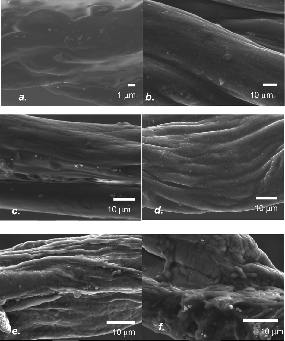 | ||
| Fig. 2 Scanning electron microscopy images of the PEDOT:PSS fibres: (a) thick with no treatment (PANI coated by CV), (b) thick with DMSO treatment (PANI coated by CV), (c) thin with no treatment (PANI coated by CV), (d) thin with DMSO treatment (PANI coated by CV), (e) thin with DMSO treatment (PANI coated by galvanostatic deposition) and (f) thin with DMSO treatment (PANI coated by potentiostatic deposition). | ||
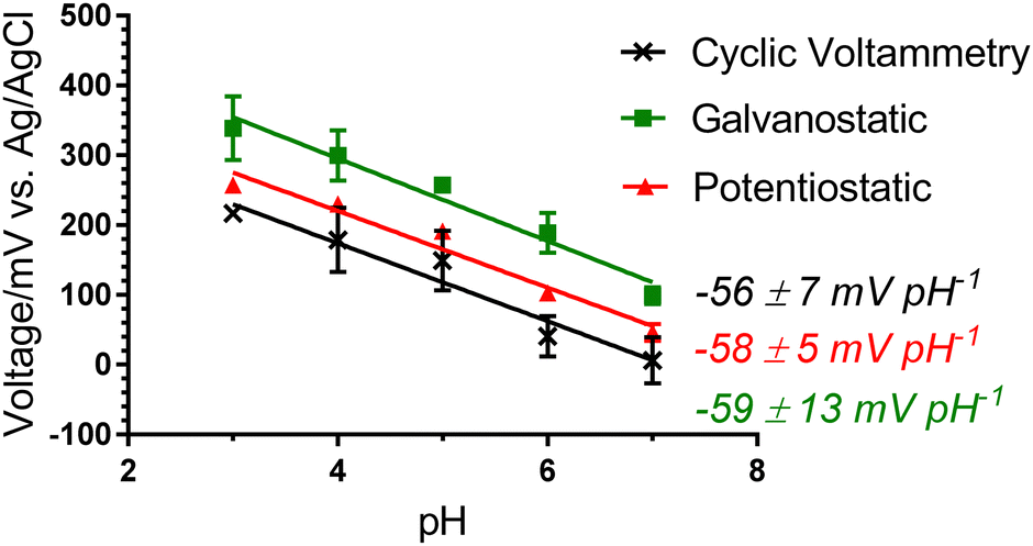 | ||
| Fig. 3 pH sensitivity of thin, DMSO-treated, wet-spun PEDOT:PSS fibres PANI-coated by CV (10 cycles), potentiostatic (600 s) and galvanostatic (300 s) techniques. The error bars represent the sample stddev of n = 3 replicate measurements. | ||
3.3. Development of wearable sensor
A wearable Ag/AgCl pseudoreference electrode was fabricated to develop a solid-state pH sensor. A requirement of a pseudoreference electrode is to present a constant voltage regardless of variation in pH and other sweat/wound-related interferences.35 Two main approaches have been adopted previously in the literature for the fabrication of pseudoreference electrodes. The first approach coated Ag/AgCl-ink onto a surface, and the second is to further dip-coat the Ag/AgCl-coated substrate with a reference ion-selective membrane (RF-ISM). Both approaches were undertaken in this research to determine the optimal pseudoreference electrode for pH analysis.The Ag/AgCl-gauze demonstrated the best and most repeatable response with a slope of −2 ± 0 mV pH−1, compared to −5 ± 1 mV pH−1 for Ag/AgCl-CF (Fig. S3, ESI†). Furthermore, the gauze fabric is more similar to typical bandages than CF. Hence, Ag/AgCl-gauze was selected for further solid-state analysis.
The wearable Ag/AgCl pseudoreference electrode (Ag/AgCl-gauze) was connected to the PANI-PEDOT:PSS fibre electrode and the potential was measured as interfering ions (NH4+, Mg2+, Ca2+, K+ and Na+) at physiologically relevant concentrations were added sequentially to a pH 4 buffered solution (Fig. 4(a)). The largest voltage change observed was ±2 mV, which was significantly smaller than 53 mV after the change to pH 5 (Fig. 4(a)) thus demonstrating pH selectivity. This shows that the fibre can sense pH effectively regardless of the sweat and wound-related interferences present.
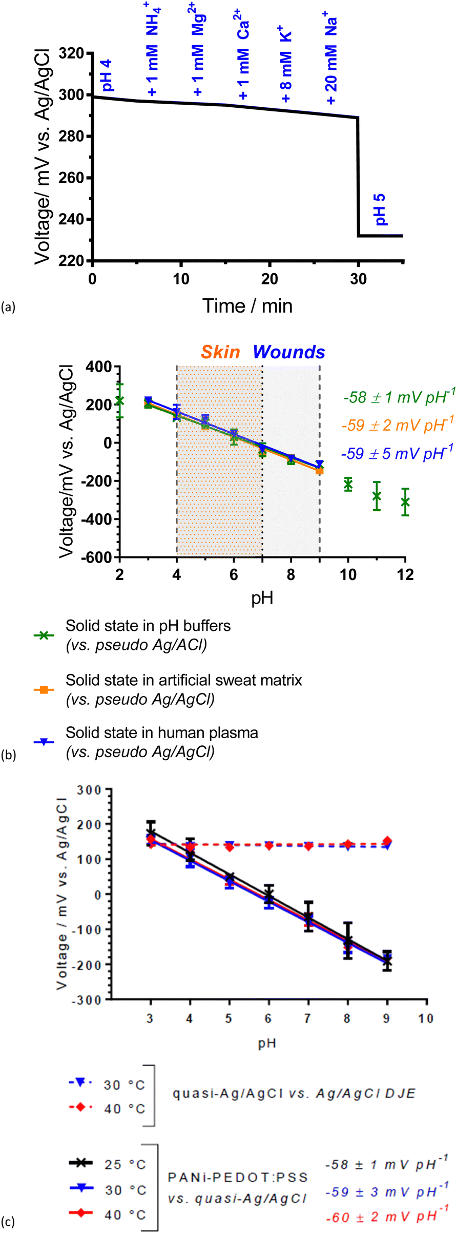 | ||
| Fig. 4 Potentiometric response of solid-state pH analysis: (a) Selectivity when various sweat-related interferences (NH4+, Mg2+, Ca2+, K+ and Na+) were added to the pH 4 aqueous samples (20 mL). (b) Response in buffered solution to varying pH levels, in pH-adjusted artificial sweat matrix and human plasma (200 μl) (vs. Ag/AgCl pseudoreference electrode). (c) Potentiometric (open circuit) response of PANI-PEDOT:PSS fibres and quasi-reference electrode in buffered solutions to varying pH levels in temperatures 25, 30 and 40 °C. Error bars represent the standard deviation of n = 3 replicate measurements. | ||
A Nernstian response of −58 ± 1 mV pH−1 was achieved over the pH range 3.0 to 9.0 with a 200.0 μL drop of analyte solution covering the electrodes of the solid-state system (Fig. 4(b)). This pH range is across the physiologically relevant pH range for skin. Likewise, the electrodes obtained a Nernstian response in both a pH-adjusted sweat matrix (common sweat interferences, e.g., 6 mM KCl) and pH-adjusted human plasma (common wound-related interferences, e.g., proteins) (Fig. 4(b)). Small volume (200.0 μL) analysis over the physiologically critical pH range for skin and wounds (pH 4.0 to 9.0) demonstrates the potential of the PANI-PEDOT:PSS fibre electrode in an epidermal patch for sweat and wound monitoring.
A near-Nernstian response of the pH sensing fibres was maintained at temperatures relevant to skin (between 25 and 40 °C), with non-significant variation (Fig. 4(c)). An increase in slope with temperature is expected from the Nernst equation (−59.2 mV pH−1 at 25 °C and −62.1 mV pH−1 at 40 °C). Wound/skin temperatures range between 31 and 37 °C and therefore the PANI-PEDOT:PSS fibres have good potential to effectively monitor skin/wound beds while being worn on the body.
| Fibre electrode | Ultimate Tensile Strength/MPa | Breaking Strain/% | Young's Modulus/GPa |
|---|---|---|---|
| PEDOT:PSS fibre | 33 ± 21 | 13 ± 2 | 0.6 ± 0.1 |
| PANI-PEDOT:PSS fibre | 32 ± 11 | 4 ± 1 | 2.0 ± 0.9 |
| Bare gauze fabric | 141 ± 25 | 9 ± 5 | 1.7 ± 0.7 |
| Ag/AgCl-gauze | 139 ± 11 | <3 ± 1 | 23.0 ± 5.0 |
PEDOT:PSS fibre (thin, DMSO-treated) showed moderate antibacterial activity (intensity = 138 ± 47 a.u.), compared to the bare gauze fabric (intensity = 945 ± 101 a.u.) that is commonly used in wound bandages (Fig. 5(a)). The antibacterial activity of the fibres was increased further with the PANI-coating, which lowered bacterial intensity further to 74 ± 2 a.u. PANI is known for its antibacterial activity due to the charged nitrogen in the PANI backbone attacking the bacterial cell wall.36 PANI has been previously used as an antibacterial agent in textiles.33
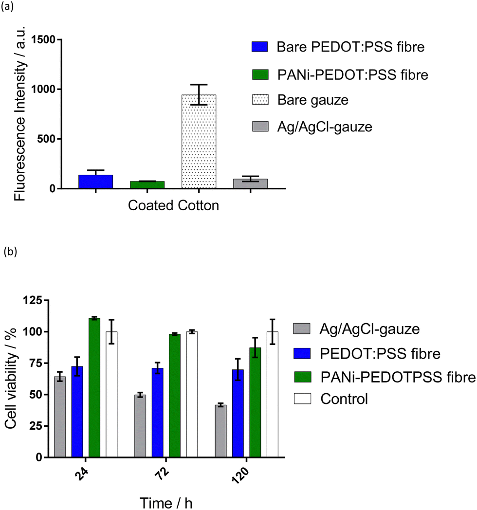 | ||
| Fig. 5 (a) Mean intensity of fluorescence (FITC, 488 nm) across a fixed area (0.217 mm2) of PANI-coated PEDOT:PSS fibre and Ag/AgCl-gauze biofouled with E. coli wild type strain expressing yellow fluorescent protein (YFP). Error bars represent the standard errors of three independent experiments. (b) Cell viability compared to control taken at three time points: days 1, 2 and 4 post sensor administration. Wells without sensors were used as controls and were considered 100% viable. Error bars represent the standard errors of three independent experiments. | ||
The Ag/AgCl-gauze exhibited a notably lower fluorescence intensity (98 ± 27 a.u.) than bare gauze fabric (941 ± 101 a.u.), demonstrating a high antibacterial activity (Fig. 5(a)). This was expected as recent evidence suggested that AgCl slowly releases silver ions, which are antibacterial.37 Previously, this antibacterial effect was proved to accelerate wound healing34 and was used as an antibacterial agent in wound dressings.38 Fluorescence imaging of the bare gauze fabric showed bacterial cells growing within the fabric (data not shown). However, the Ag/AgCl-coating has discouraged this growth or attachment of the bacteria, protecting the surface of the reference electrode from bacterial growth. These results highlight the potential of both the PANI-PEDOT:PSS fibres and Ag/AgCl-gauze in reducing bacteria in an epidermal patch during exercise and/or reducing the likelihood of an infection in wounds.
The cell viability on the PEDOT:PSS fibres (thin, DMSO-treated) showed a significant decrease (p < 0.05) of 29% after 24 h compared to the empty well control (Fig. 5(b)). The PANI-coated PEDOT:PSS fibres demonstrated no significant change in cell viability compared to the control. There average cell viability number seems to be lower at longer timepoints and therefore further experiments need to be conducted to confirm the biocompatibility of these materials. Ag/AgCl-gauze induced a toxic reaction in the cells, reducing the viability by 37% after 24 h compared to the control (p < 0.05). A possible explanation is the presence of methyl carbitol in the Ag/AgCl ink used to coat the gauze since previous studies have shown that Ag/AgCl is not toxic.39 Although future studies are needed to investigate the biocompatibility of the solid-state pair, this proof-of-concept study shows promise for the use in wearable sensors.
4. Conclusions
Successful pH-sensing fibre electrodes have been developed based on PANI and PEDOT:PSS. PEDOT:PSS fibres were made by wet-spinning followed by solvent treatment with DMSO. Subsequent potentiostatic electropolymerisation of PANI onto the surface facilitated pH sensing. The formulation of a wearable Ag/AgCl pseudoreference involved curing Ag/AgCl ink onto gauze fabric (analogous to wound dressings). The pH sensing electrode (PANI-PEDOT:PSS) was successful when measured in a low volume sensing configuration vs. the wearable pseudoreference electrode. The fibre and gauze electrodes demonstrated a selective, Nernstian response in both pH-adjusted sweat matrices (common sweat interferences, e.g., 6 mM KCl) and pH-adjusted human plasma (common wound-related interferences, e.g., proteins). Significant antibacterial properties were demonstrated for both the pH sensing and reference electrode. Additionally, the PANI-PEDOT:PSS fibres showed promising biocompatible properties. Next steps include enhancing the strength of the PANI-PEDOT:PSS fibres in addition to further biocompatibility investigation.Conflicts of interest
There are no conflicts to declare.Acknowledgements
The authors thank the University of Surrey for providing funding for a studentship for RES. The authors thank the EPSRC for providing the capital funding that funded the Raman microscope used in this work (EP/M022749/1).References
- L. Manjakkal, S. Dervin and R. Dahiya, Flexible potentiometric pH sensors for wearable systems, RSC Adv., 2020, 10(22), 8594–8617, 10.1039/d0ra00016g.
- J. Posnett and P. J. Franks, The burden of chronic wounds in the UK, Nursing Times, vol. 104, 2008, pp. 44–45 Search PubMed.
- C. R. Kruse, K. Nuutila, C. C. Y. Lee, E. Kiwanuka, M. Singh, E. J. Caterson, E. Eriksson and J. A. Sorensen, The external microenvironment of healing skin wounds, Wound Rep. Reg., 2015, 23, 456–464 CrossRef PubMed.
- L. R. Bennison, C. N. Miller, R. J. Summers, A. M. B. Minnis, G. Sussman and W. McGuiness, The pH of wounds during healing and infection: a descriptive literature review, Wound Practise Res., 2017, 25, 63–69 Search PubMed.
- Y. Tang, L. Zhong, W. Wang, Y. He, T. Han, L. Xu, X. Mo, Z. Liu, Y. Ma, Y. Bao, S. Gan and L. Niu, Recent Advances in Wearable Potentiometric pH Sensors, Membranes, 2022, 12(5), 504 CrossRef CAS PubMed.
- T. Guinovart, M. Parrilla, G. A. Crespo, F. X. Rius and F. J. Andrade, Potentiometric sensors using cotton yarns, carbon nanotubes and polymeric membranes, Analyst, 2013, 138, 5208–5215 RSC.
- J. N. Xu, Z. Zhang, S. Y. Gan, H. Gao, H. J. Kong, Z. Q. Song, X. M. Ge, Y. Bao and L. Niu, Highly stretchable fiber-based potentiometric ion sensors for multichannel real-time analysis of human sweat, ACS Sens., 2020, 5, 2834–2842 CrossRef CAS PubMed.
- A. Bandodkar, V. Hung, W. Jia, G. Valdés Ramírez, J. Windmiller, A. Martinez, P. Ramírez, G. Chan, K. Kerman and J. Wang, Tattoo-based potentiometric ion-selective sensors for epidermal pH monitoring, Analyst, 2013, 138, 123–128 RSC.
- T. Guinovart, G. Valdes-Ramirez, J. R. Windmiller, F. J. Andrade and J. Wang, Bandage-based wearable potentiometric sensor for monitoring wound pH, Electroanalysis, 2014, 26, 1345–1353 CrossRef CAS.
- R. Wang, Q. Zhai, Y. Zhao, T. An, S. Gong, Z. Guo, Q. Q. Shi, Z. Yong and W. Cheng, Stretchable gold fiber-based wearable electrochemical sensor toward pH monitoring, J. Mater. Chem. B, 2020, 8, 3655–3660 RSC.
- D. O. Reid, R. E. Smith, J. Garcia-Torres, J. F. Watts and C. Crean, Solvent Treatment of Wet-Spun PEDOT: PSS Fibers for Fiber-Based Wearable pH Sensing, Sensors, 2019, 4213 CrossRef CAS PubMed.
- L. Q. Balaban, J. Merrin, R. Chait, L. Kowalik and S. Leibler, Bacterial persistance as a phenotypic switch., Science, 2004, 305, 1622–1625 CrossRef PubMed.
- H. Okuzaki, Y. Harashina and H. Yan, Highly conductive PEDOT:PSS microfibres fabricated by wet-spinning and dip-treatment in ethylene glycol, Eur. Polym. J., 2009, 45, 256–261 CrossRef CAS.
- Y. Yang, Y. Xi, J. Li, W. Guodong and N. I. Klyui, Flexible supercapacitors based on polyaniline arrays coated graphene aerogel electrodes, Nanoscale Res. Lett., 2017, 12, 394 CrossRef PubMed.
- R. Gupta, M. Singhal, S. K. Nataraj and D. N. Srivastava, A potentiostatic approach of growing polyaniline nanofibers in fractal morphology by interfacial electropolymerisation, RSC Adv., 2016, 6, 110416–110421 RSC.
- H. Y. Y. Nyein, W. Gao, Z. Shahpar, S. Emaminejad, S. Challa, K. Chen, H. M. Fahad, L. C. Tai, H. Ota, R. Davis and A. Javey, A wearable electrochemical platform for noninvasive simultaneous monitoring of Ca2+ and pH, ACS Nano, 2016, 10, 7216–7224 CrossRef CAS PubMed.
- M. Parrilla, J. Ferre, T. Guinovart and F. Andrade, Wearable potentiometric sensors based on commercial carbon fibres for monitoring sodium in sweat, Electroanalysis, 2016, 28, 1267–1275 CrossRef CAS.
- R. E. Smith, S. Totti, E. Velliou, P. Campagnolo, S. M. Hingley-Wilson, N. I. Ward, J. R. Varcoe and C. Crean, Sens. Actuators, B, 2019, 287, 338–345 CrossRef CAS.
- Y. Xia, K. Sun and J. Ouyang, Solution-processed PEDOT:PSS films with conductivities as indium tin oxide through a treatment with mild and weak organic acids, Adv. Mater., 2012, 24, 2146–2151 Search PubMed.
- J. Wan, Y. Xia and J. Fang, et al., Solution Processed Transparent Conducting Electrodes for Flexible Organic Solar Cells, with 16.61% Effciency, Nano-Micro Lett., 2021, 13, 44 CrossRef PubMed.
- J. Zhang, S. Seyedin, S. Qin, P. A. Lynch, Z. Wang, W. Yang, X. Wanga and J. M. Razal, Fast and scalable wet-spinning of highly conductive PEDOT:PSS fibers enables versatile applications, J. Mater. Chem. A, 2019, 7, 6401–6410 RSC.
- M. O. P. Kara and M. W. Frey, Effects of solvents on the morphology and conductivity of poly(3,4-ethylenedioxythiophene):Poly(styrenesulfonate) nanofibers, J. Appl. Poly. Sci., 2014, 131, 40305 CrossRef.
- R. Sarabia-Riquelme, R. Andrews, J. E. Anthony and M. C. Weisenberger, Highly conductive wet-spun PEDOT:PSS fibers for applications in electronic textiles, J. Mater. Chem. C, 2020, 8, 11618–11630 RSC.
- S. Garreau, G. Louarn, J. P. Buisson, G. Froyer and S. Lefrant, In situ spectroelectrochemical Raman studies of poly(3,4-ethylenedioxythiophene) (PEDT), Macromolecules, 1999, 32, 6807–6812 CrossRef CAS.
- S. H. Chang, C. H. Chiang, F. S. Kao, C. L. Tien and C. G. Wu, Unraveling the enhanced electrical conductivity of PEDOT:PSS thin films for ITO-free organic photovoltaics, IEEE Photon. J., 2015, 3, 8400307 Search PubMed.
- L. Zhang, H. Deng, S. Liu, Q. Zhang, F. Chen and Q. Fu, Enhanced thermoelectric properties of PEDOT:PSS films via a novel two-step treatment, RSC Adv., 2015, 105592–105599 RSC.
- B. Sarkar, M. Jaisal and D. K. Satapathy, Swelling kinetics and electrical charge transport in PEDOT:PSS thin films exposed to water vapor, J. Phys.: Condes. Matter., 2018, 30, 225101 CrossRef PubMed.
- S. Y. Ciu and S. M. Park, Electrochemistry of conductive polymers XXIII: polyaniline growth studied by electrochemical quartz crystal microbalance measurements, Syn. Met., 1999, 105, 91–98 CrossRef.
- H. Tang, Y. Ding, C. Zang, J. Gu, Q. Shen and J. Kan, Effect of temperature on electrochemical degradation of polyaniline, Int. J. Electrochem. Sci., 2014, 9, 7239–7252 CrossRef.
- B. Frontana-Uribe, S. Ludwigs and J. Heinze, Electrochemistry of conducting polymers: Persistent models and new concepts, Chem. Rev., 2010, 110, 4724–4771 CrossRef PubMed.
- L. Arsov, W. Plieth and G. Kossmehl, Electrochemical and Raman spectroscopic study of polyaniline; influence of the potential on the degradation of polyaniline., J. Solid State Electrochem., 1998, 2, 355–361 CrossRef CAS.
- T. Lindfors and A. Ivaska, Raman based pH measurements with polyaniline., J. Electroanal. Chem., 2005, 580, 320–329 CrossRef CAS.
- M. C. Bernard and A. Hugot-Le Goff, Quantitative characterization of polyaniline films using Raman spectroscopy I; Polaron lattice and bipolaron, Electrochim. Acta, 2006, 52, 595–603 CrossRef CAS.
- S. Mondal, K. Prasad and N. Munichandraiah, Analysis of electrochemical impedance of polyaniline films prepared by galvanostatic, potentiostatic and potentiodynamic methods, Synth. Met., 2005, 148, 275–286 CrossRef CAS.
- M. W. Shinwari, D. Zhitomirsky, I. A. Deen, P. R. Selvaganapathy, M. J. Deen and D. Landheer, Microfabricated reference electrodes and their biosensing applications., Sensors, 2010, 10, 1679–1715 CrossRef CAS PubMed.
- D. Seshadri and N. V. Bhat, Use of polyaniline as an antimicrobial agent in textiles., Indian J. Fibre Textile Res., 2005, 30, 204–206 CAS.
- J. B. Wright, K. Lam, A. G. Buret, M. E. Olson and R. E. Burrell, Early healing events in a porcine model of contaminated wounds: Effects of nanocrystalline silver on matrix metalloproteinases, cell apoptosis, and healing, Wound Rep. Reg., 2002, 10, 141–151 CrossRef PubMed.
- A. Adams, E. Santschi and M. Mellencamp, Antibacterial properties of a silver chloride-coated nylon wound dressing., Vet. Surg., 1999, 28, 219–225 CrossRef CAS PubMed.
- G. Voskerician, C. C. Liu and J. M. Anderson, Electrochemical characterisation and in vivo biocompatibility of a thick-film printed sensor for continuous in vivo monitoring., IEEE Sens. J., 2005, 5, 1147–1157 CAS.
Footnote |
| † Electronic supplementary information (ESI) available. See DOI: https://doi.org/10.1039/d3ma00711a |
| This journal is © The Royal Society of Chemistry 2024 |