 Open Access Article
Scaling up the charge transfer on Pd@Ti3C2Tx–TiO2 catalysts: a sustainable approach for H2 generation via water splitting†
Muhammad Zeeshan
Abid
 a,
Khezina
Rafiq
 *a,
Abdul
Rauf
a,
Raed H.
Althomali
 b and
Ejaz
Hussain
 *a
*a
aInstitute of Chemistry, Inorganic Materials Laboratory 52S, The Islamia University of Bahawalpur, Bahawalpur-63100, Pakistan. E-mail: khezina.rafiq@iub.edu.pk; ejaz.hussain@iub.edu.pk
bDepartment of Chemistry, College of Arts and Science, Prince Sattam Bin Abdulaziz University, Wadi Al-Dawasir-11991, Saudi Arabia
First published on 21st December 2023
Abstract
The increasing energy demands have led modern societies to search for green and renewable alternatives that can replace traditional energy sources (i.e. fossil fuels). The aim of this project is to generate sustainable hydrogen from renewable sources. For this purpose, we synthesized highly active MXene-supported catalysts (Pd@Ti3C2Tx–TiO2). In this work, Pd2+ ions were directly reduced on Ti3C2Tx surfaces without using an additional reducing agent. Morphology and optical characteristics were evaluated using XRD, UV-vis/DRS, SEM, TEM, Raman, and FT-IR techniques. Chemical compositions and surface terminations of the catalysts were examined via EDX and XPS techniques. It was found that low Fermi levels of Pd@Ti3C2Tx effectively quench photogenerated electrons and facilitate H2 evolution without using any sacrificial reagents. This innovative approach enhanced the stability and ability of TiO2 to effectively transfer the photoinduced charges on the Pd@Ti3C2Tx cocatalysts. The role of Pd was elucidated and demonstrated for hydrogen generation progress. The results suggest that the presence of Pd metal over Ti3C2Tx surfaces boosted H2 generation. Overall, Pd@Ti3C2Tx–TiO2 catalysts delivered 35.11 mmol g−1 h−1 of hydrogen. Thus, it was concluded that the as-synthesized catalysts hold promise to replace costly and conventional hydrogen generation technologies.
Introduction
Energy shortages have become a real challenge, specifically for the developing countries. However, this issue is less common in developed countries because of multiple alternatives (i.e., nuclear, wind, and hydropower sources). In the world, the most common and conventional sources of energy are fossil fuels (coal, petroleum, and natural gas). The combustion of fossil fuel is becoming a serious threat to our environment and climate,1 of which the climate change is proof. Moreover, increase in human population and industrialization is becoming a source of torment and curse.2 Undoubtedly if the environment is not safe, we should be ready for the ruin and end of the world.To develop energy sources other than fossil fuels, it is essential to explore green and renewable energy sources.3 Therefore, it is urgent to generate hydrogen energy that can not only meet energy demands but also protect our climate and environment. Generally, the production of hydrogen via water splitting is hectic and challenging because water is an extremely stable molecule, and its splitting needs ∼237 KJ mol−1 of energy. Although various methods have been reported for hydrogen generation, such as electrolysis, photolysis, thermolysis, and photoelectrolysis,4,5 they have many drawbacks. The use of solar radiation combined with photocatalysts is believed to have the potential to replace conventional fossil fuels. The conversion of solar energy into chemical energy is not only reliable but also a practically sustainable approach.6,7 Thus, the utilization of advanced, reliable, and stable catalysts can be practically helpful in generating hydrogen energy from renewable sources, i.e. water and biomass.8
Since the last few decades, water splitting has attracted significant attention as a sustainable and eco-friendly approach for renewable energy production.9 Up to now, various transition metal oxides (i.e. TiO2, CuO, and ZnO10–13), mixed metal oxides (i.e. Zn3V2O8 and SrTiO314), metal sulphides (i.e. CdS, ZnS, CuS, and CdZnS15–17), perovskites and chalcogenides,18,19 and metal and non-metal doped catalysts have been employed for water reduction.20,21 Similarly, graphene and g-C3N4 supported metal or non-metal fabricated catalysts22–25 have been extensively utilized for H2 generation. It has been found and well justified that the ability of TiO2 to split water can be extended by the use of cocatalysts.26 The employment of cocatalysts on TiO2 has been found to be more effective for sustainable water splitting.27,28 Cocatalysts with the ability to quench the electrons from semiconductor systems can be effective for excellent charge transportation, specifically in water-splitting reactions.29,30 The higher charge separation ability of the cocatalyst is attributed to its chemical properties (i.e., conductivity and stability). Furthermore, cocatalysts certainly enhance active sites and the life of the photoreaction.30,31 Numerous noble metal cocatalysts like Pd, Pt, Au, Ru, Rh, Os and Ag are considered to be crucial for enhancing photocatalytic performances.32–34
MXenes (Ti3C2Tx), where ‘Tx’ represents surface terminations, ‘T’ corresponds to functional groups like –F, –OH, ![[double bond, length as m-dash]](https://www.rsc.org/images/entities/char_e001.gif) O, etc., while ‘x’ denotes variability.35 MXenes have distinct chemical characteristics and can be employed as a cocatalyst with other semiconductor systems.36 Due to two-dimensional structures, a substantial surface area, and chemical properties, Ti3C2Tx enhances the electrical conductivity of the host semiconductor.37 These unique characteristics make MXenes attractive cocatalysts for higher charge transfer to accelerate the photocatalytic water-splitting reactions.38 The utilization of MXenes as a cocatalyst has been found to be very successful in enhancing the photocatalytic performances of semiconductor systems. Several reports have been found very supportive for the use of Ti3C2 as a cocatalyst. Examples of such reports are CdZnS@Ti3C2,39 CdS@Ti3C2,40 BiVO4@Ti3C2,41 g-C3N4@Ti3C242 and TiO2@Ti3C2.43 For example, g-C3N4 with Ti3C2 cocatalysts exhibited higher hydrogen generation efficiencies (seven times higher than bare g-C3N4).44 Similarly, bare Cd0.5Zn0.5S is less stable and a bad semiconductor due to charge recombination during photoreaction, but when coupled with Ti3C2, its photocatalytic efficiency was remarkably enhanced.45
O, etc., while ‘x’ denotes variability.35 MXenes have distinct chemical characteristics and can be employed as a cocatalyst with other semiconductor systems.36 Due to two-dimensional structures, a substantial surface area, and chemical properties, Ti3C2Tx enhances the electrical conductivity of the host semiconductor.37 These unique characteristics make MXenes attractive cocatalysts for higher charge transfer to accelerate the photocatalytic water-splitting reactions.38 The utilization of MXenes as a cocatalyst has been found to be very successful in enhancing the photocatalytic performances of semiconductor systems. Several reports have been found very supportive for the use of Ti3C2 as a cocatalyst. Examples of such reports are CdZnS@Ti3C2,39 CdS@Ti3C2,40 BiVO4@Ti3C2,41 g-C3N4@Ti3C242 and TiO2@Ti3C2.43 For example, g-C3N4 with Ti3C2 cocatalysts exhibited higher hydrogen generation efficiencies (seven times higher than bare g-C3N4).44 Similarly, bare Cd0.5Zn0.5S is less stable and a bad semiconductor due to charge recombination during photoreaction, but when coupled with Ti3C2, its photocatalytic efficiency was remarkably enhanced.45
Surprisingly, the work function (ϕ) of Ti3C2 is (5.78 eV)46 is comparable to the noble metals,47,48 and thus it has an inherent ability to quench free electrons from semiconductor systems. The finding of this study depicts that the stability, conductivity, and electron quenching ability of Ti3C2 can be enhanced by fabricating it with noble metals.49 Among transition metals, palladium (Pd) exhibits a higher electron quenching ability for various photocatalytic reactions.50 The fabrication of Ti3C2 surface with Pd can provide additional active sites for sustainable H2 evolution reactions.51,52
This work aims to explore the effectiveness of Pd on MXenes (Ti3C2Tx) with higher charge transport for efficient H2 evolution. This study further demonstrates the novel design and sustainable approach for green fuel production (hydrogen energy) via water-splitting reactions. In addition, the results of this study depict and justify the mutual role of TiO2 (semiconductor) and Pd@Ti3C2Tx cocatalyst. For the very first time, the mechanistic insights have been explored and explained with evidence. The work reported herein demonstrates and justifies the synergistic effects between TiO2 and Pd@MXenes cocatalysts that offer excellent insights about the design of catalyst synthesis, optimized role of semiconductor systems and cocatalysts, and progress of photoreaction. In brief, this work contributes to the fundamental understanding of catalyst engineering and its effectiveness for sustainable hydrogen energy systems.
Experimental
Chemicals
The following chemicals were used to prepare the catalysts: Degussa P25 (Evonik Germany), Ti3AlC2 (Forsman Scientific Beijing), Pd(O2CCH3)2(99.0% Sigma-Aldrich), 40% HF Solution (MERK, 48%), absolute ethanol (99.0% Sigma-Aldrich), and distilled water (PAEC-PK).Catalyst synthesis
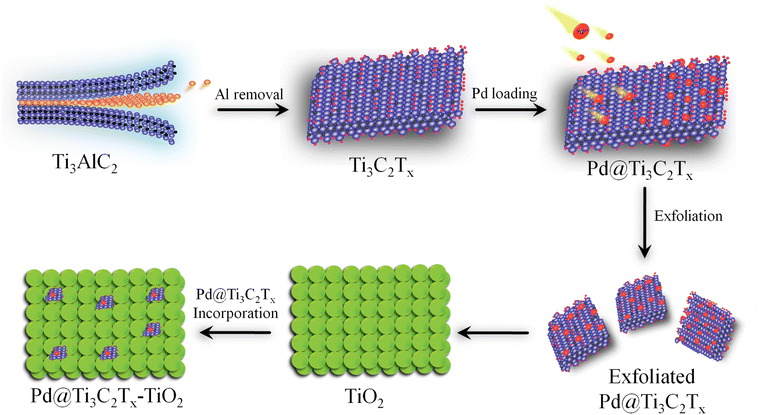
Ti3C2Tx was prepared by exfoliating the Al layers from MAX (Ti3AlC2).53 Briefly, 2 g of Ti3AlC2 was gradually transferred to 60 mL HF solution (40%) in a 100 mL Teflon reactor (Techinistro/China). This precursor was continuously stirred for 8 h under ambient conditions.54 After obtaining the slurry (dull black), progressive slurry was separated via multiple centrifugations (at 5000 rpm, 20 min for each) and a similar process was repeated multiple times (seven-eight times) for washing with distilled water. Note: at this stage, careful washing is mandatory to leach and eliminate HF properly. The washing of the MXene slurry was continued until the pH of the waste liquid approached 7 to 7.2. Finally, the product was dried under vacuum conditions at 70 °C for 10 h.55 The protocol employed for the synthesis of Pd@Ti3C2Tx–TiO2 is demonstrated in Fig. 1.To develop and fabricate the Ti3C2Tx surfaces with palladium contents, typically, 500 mg of Ti3C2Tx is dispersed in 100 mL of deoxygenated water (i.e., water obtained after 20 min purging with high-purity dry N2) and sonicated for 25 min. Then, a nominal amount of Pd(O2CCH3)2 was added to the Ti3C2Tx slurry to maintain the Pd2+ to Ti3C2Tx ratios (2![[thin space (1/6-em)]](https://www.rsc.org/images/entities/char_2009.gif) :
:![[thin space (1/6-em)]](https://www.rsc.org/images/entities/char_2009.gif) 98). After vigorous stirring for 5 h, Pd@Ti3C2Tx was thoroughly washed first with deionized water and then with ethanol (analytical grade). Finally, the 2%-Pd@Ti3C2Tx powder was dried under vacuum conditions at 70 °C for 10 h.56 Various Pd@Ti3C2Tx ratios (1%, 2%, and 3%) were prepared under similar conditions to examine the impact of Pd loading over the Ti3C2Tx surfaces.
98). After vigorous stirring for 5 h, Pd@Ti3C2Tx was thoroughly washed first with deionized water and then with ethanol (analytical grade). Finally, the 2%-Pd@Ti3C2Tx powder was dried under vacuum conditions at 70 °C for 10 h.56 Various Pd@Ti3C2Tx ratios (1%, 2%, and 3%) were prepared under similar conditions to examine the impact of Pd loading over the Ti3C2Tx surfaces.
To develop Pd@Ti3C2Tx–TiO2, appropriate amounts of Pd@Ti3C2Tx (2.5, 5.0 7.5, and 10% W/W) were dispersed (via sonication) in 40 mL of distilled water. Then, TiO2 (200 mg) was dispersed in 30 mL of deoxygenated water. To produce a uniform mixture, the Pd@Ti3C2Tx slurry was gradually transferred to TiO2 suspensions and the mixture was stirred/sonicated repeatedly for 3 h. After confirming the phase transformation, the precipitates were rinsed with distilled water. Using vacuum atmosphere, catalysts were dried at 70 °C for 10 h and preserved for characterisations and photoreactions.
Characterizations
To get insights into their atomic arrangements and crystallographic properties, an XRD instrument (Bruker D2 Phaser) was used in the 2θ range from 5–80° with a 2° min−1 scan rate. To study the structural characteristics of synthesized materials, Raman spectra were recorded using a Raman spectrometer RMP-500/JASCO. An infrared spectrometer Bruker Alpha Platinum (ATR mode) was used to measure the Fourier transform infrared (FTIR) results collected in the 400–4000 cm−1 range. To determine the morphology and elemental composition, FEI-Nova-450/Nano SEM equipped with an EDX detector was employed. A JEOL model JEM 2100 F instrument was used to investigate images generated via TEM and high-resolution TEM (HRTEM). To investigate the surface morphology at the nanometer scale, atomic force microscopy (AFM) was performed using an AFM-5500/Agilent-USA. The oxidation states and terminations were examined using an X-ray photoelectron spectrometer (Thermo ESCALAB 250Xi) coupled with an Al Ka X-ray source (1486.6 eV). To measure the optical properties via diffuse reflectance spectroscopy, UV-2550/Shimadzu was used for the powder sample. Photoluminescence (PL) spectra were achieved using LS-45, PerkinElmer spectrometer. A Micromeritics-Tristar II 3020 analyzer was employed to examine the specific surface areas based on the Brunauer–Emmett–Teller method. Solartron impedance analyzer-1260 was employed for EIS analysis, whereas the photo-responses were monitored on a conventional three-electrode system (λ > 420 nm).Experiments for water-splitting reactions
The photocatalytic H2 production activities were performed using a solar simulator (94043A/450W Xenon lamp). For photoreactions, a source with an AM1.5 filter and output power of 100 mW cm−2 was used for all catalysts. For each photoreaction, 25 mg of photocatalysts were dispersed in 40 mL of deionized water in a 100 mL Pyrex reactor. Note: in order to remove dissolved oxygen contents, the reaction mixture was purged using high-purity argon (Ar) for 25 min prior to starting the photocatalytic reactions. During the photoreaction, gas samples were collected from the headspace of the photoreactor using a syringe (0.5 mL sizes) at regular intervals, and hydrogen (H2) generation was monitored on GC-TCD (Shimadzu 2010/Japan). It is important to declare that high-purity argon was used as the carrier gas to the GC-TCD outfitted with a molecular sieve capillary column. The H2 gas produced was quantified using the system's internal calibration curves, and the results for each photoreaction were compared. Units of mmol g−1 and mmol g−1 h−1 were used to measure the rates of H2 generation. The apparent quantum yield (AQY) for each photoreaction was calculated by employing the formula represented in eqn (1).57,58 | (1) |
n H2 represents the quantity of hydrogen produced (mol), NA is Avogadro's number (mol−1), P is the power density of light (W m−2), h is Planck's constant (J s), A is the irritation area (m2), c is the speed of light (m s−1), t is time (sec), and λ is the wavelength (m).59
Results and discussion
Structural characteristics
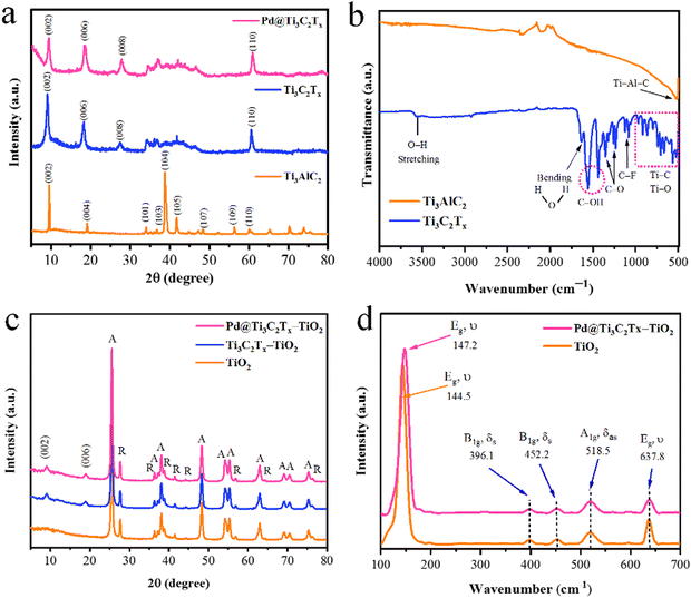
The structural characteristics of synthesized catalysts were obtained using XRD, Raman, and FT-IR techniques. The results are illustrated in Fig. 2. It has been found that the XRD pattern of the precursor material Ti3AlC2 (MAX phase) was well matched to JCPDS No. 52-0875, which confirms its purity and crystalline structure.60 The extraction of Al atoms from Ti3AlC2 is evident from the shifting of the (002) peak towards smaller angles. The XRD (002) peaks of Ti3C2Tx display broader profiles as compared to Ti3AlC2. Additionally, the complete depletion of Al is further confirmed by the absence of a peak at 39° (104). These significant changes confirm the MXene's phase purity achieved in the current work.61 It has been further justified that due to the deposition of Pd over the Ti3C2Tx surfaces, the intensity of the peak (002) decreased. In the XRD pattern, no additional peaks corresponding to Pd were observed, as shown in Fig. 2a.62The FT-IR results (Fig. 2b) of MAX phases exhibit vibrations located at 498 cm−1 that correspond to the Ti–Al–C bond (bending vibrations). The conversion of MAX to MXene was confirmed by the removal of the peak primarily observed at 498 cm−1. The appearance of new peak patterns in FT-IR results was attributed to Ti–O, C–F, C–O, and C–OH bonds, confirming the formation of Ti3C2Tx (i.e., MXene).63 In the FTIR spectra of Ti3C2Tx, the vibrations at 567 cm−1, 707 cm−1, 854 cm−1, and 921 cm−1 represent the Ti–C bond stretching vibrations.64 It has been reported that the interaction between atoms of Ti and the O–H groups on the surface of Ti3C2Tx causes deformation vibrations of the Ti–O bond at 617 cm−1.65 The vibrations at 1057 and 1097 cm−1 indicate the existence of C–F functional groups, whereas the peaks at 1229 cm−1 and 1343 cm−1 were attributed to oxygen-containing (C–O) functional groups whereas the O–H terminations were detected at 1399 and 1437 cm−1.66 The existence of OH is due to the absorbed external water through absorption peaks at 1636 and 3437 cm−1.67 The results confirm the formation of a multilayer Ti3C2Tx structure. During the etching, the elimination of the Al layers will cause the beginning of surface terminations (Tx) like hydroxyl (–OH), oxygen (![[double bond, length as m-dash]](https://www.rsc.org/images/entities/char_e001.gif) O), or fluorine (–F) groups.
O), or fluorine (–F) groups.
The powder XRD patterns of TiO2, Ti3C2Tx–TiO2, and Pd@Ti3C2Tx–TiO2 have been revealed in Fig. 2c. The peaks of rutile and anatase are distinctive in the pattern; however, the anatase phase of TiO2 dominates due to higher percentage.68 The additional peaks are due to the existence of as-synthesized Ti3C2Tx–TiO2 and Pd@Ti3C2Tx–TiO2 catalysts. The additional peaks at 2 theta 9.9° (002) and 19.9° (006) correspond to the Ti3C2Tx diffraction peaks.69 Note: neither the peak positions of anatase nor the peak of rutile changed, which indicates the stable morphologies of as-developed catalysts. Moreover, the deposition of Pd@Ti3C2Tx on TiO2 did not alter the TiO2 crystal lattice or phase transition between anatase and rutile structures.56
Raman spectroscopy was employed to investigate the vibrational and rotational modes of catalysts. This technique provides valuable information about the structure, chemical composition, and physical properties.70 The Raman spectroscopy results of TiO2 and Pd@Ti3C2Tx–TiO2 photocatalysts are depicted in Fig. 2(d). In the Raman spectrum, the TiO2 sample shows prominent peaks at 144.5 cm−1 (Eg), 396.1 cm−1 (B1g), 452.2 cm−1 (A1g), 518.5 cm−1 (B1g), and 637.8 cm−1 (Eg). The Eg mode of vibrations corresponds to the oxygen in the O–Ti–O bond.71 The modes (A1g and B1g) are associated with the anti-symmetric and symmetric bending vibrations of the O–Ti–O bonds in anatase TiO2. A weak rutile peak is observed at 452.2 cm−1 due to its low concentration. The fabrication of TiO2 with Pd@Ti3C2Tx shifts the Eg peak from 144.5 cm−1 to 147.2 cm−1. This shifting was attributed to interactions of Pd@Ti3C2Tx with TiO2 catalyst.72
Morphological analysis
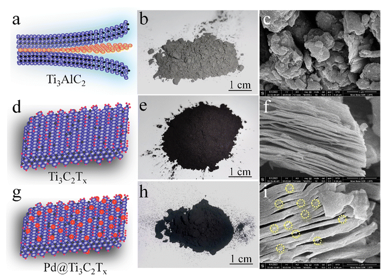
The surface features and structural morphology of catalysts were determined with scanning electron microscopy (SEM). The schematic illustration, digital photograph, and SEM results of the starting material Ti3AlC2, as well as Ti3C2Tx and Pd@Ti3C2Tx, are demonstrated in Fig. 3a–i. The scheme used herein to achieve the required morphology of catalysts clarifies the transformation process from Ti3AlC2 to Ti3C2Tx and the subsequent deposition of Pd onto Ti3C2Tx (Pd@Ti3C2Tx). The digital photographs (Fig. 3b, e and h) provide evidence of the apparent changes occurring during the conversion of Ti3AlC2 to Ti3C2Tx and the fabrication of Pd metal over Ti3C2Tx.73Fig. 3c represents the SEM micrograms of commercial Ti3AlC2 particles. Fig. 3f suggests that the etching of Ti3AlC2 produced the unsymmetrical accordion-like multilayer structures, which justify the Ti3C2Tx developments.74 The SEM results (Fig. 3i) reveal the distribution and morphology of the deposited Pd particles over the Ti3C2Tx surfaces.The SEM images of Pd@Ti3C2Tx–TiO2 are demonstrated in Fig. 4a and b. The results elucidate the uniform dispersion of TiO2 particles having exfoliated Pd@Ti3C2Tx structures. The absence of agglomeration is due to the layered structure of Ti3C2Tx that reduces the TiO2 accumulations.75 It has been noted that the intimate contact between TiO2 (101) and Ti3C2Tx facets in the photoreaction facilitates the transfer of photogenerated electrons to the active sites where the rate of water reduction is remarkably enhanced. Surprisingly, Pd nanoparticles located on Ti3C2Tx remain un-oxidized (i.e., exist in a metallic state) due to the free electrons of MXene.56 The lattice images in Fig. 4c display the interplanar spacing of Pd (111) at 0.22 nm. TEM results confirm the presence of Pd particles on the Ti3C2Tx surfaces. The SEM, TEM, and XPS further confirm the high degree of dispersion and metallic state of palladium. It is well accepted that Pd, in its metallic state, quenches more electrons and is utilized in the H+ reductions in photoreactions.68,76
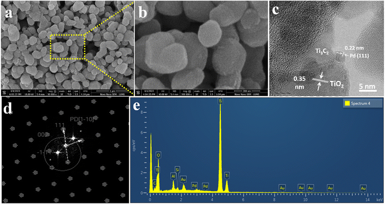 | ||
| Fig. 4 SEM images at (a) 1 μm and (b) 200 nm, (c) HR-TEM, (d) TEM diffraction pattern, and (e) EDX analysis of Pd@Ti3C2Tx–TiO2. | ||
The HRTEM result clearly justifies the high crystalline nature of metallic Pd (Fig. 4c and d). Moreover, the existence of crystalline structures of palladium can be revealed by concentric rings.77 The TEM results provide important information about the structural conformations of as-fabricated catalysts. The EDX (Fig. 4e) results confirm the purity and existence of elements in the Pd@Ti3C2Tx–TiO2 catalysts.
Atomic force microscopy (AFM) provides essential insights into the surface roughness, morphology, and size distribution of catalysts at high resolutions.78 In this study, AFM (5500/Agilent-USA) was employed to examine the Pd@Ti3C2Tx–TiO2 photocatalysts, and the resulting 2D topographical results are presented in Fig. 5a and b. The scrutinized area of 2.35 × 2.35 μm was covered to evaluate the particle size distribution in 3 to 10 nm ranges. The average particle size was 9.5 nm; see Fig. 5c for the size distribution. Additionally, Fig. 5d and e display three-dimensional images, revealing the surface roughness and morphology of Pd@Ti3C2Tx–TiO2 photocatalysts.79
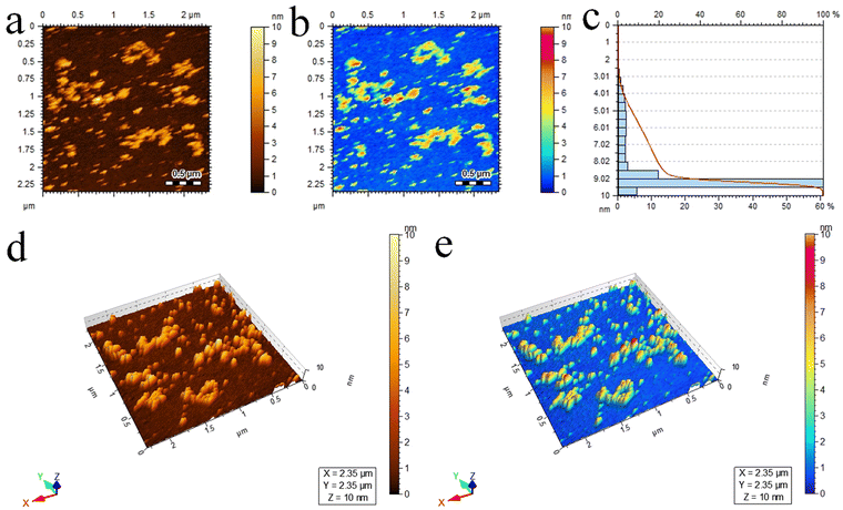 | ||
| Fig. 5 AFM results of Pd@Ti3C2Tx–TiO2 photocatalysts: (a) and (b) 2D-tapping modes, (c) size distribution and (d) and (e) 3D images. | ||
Terminations and chemical compositions
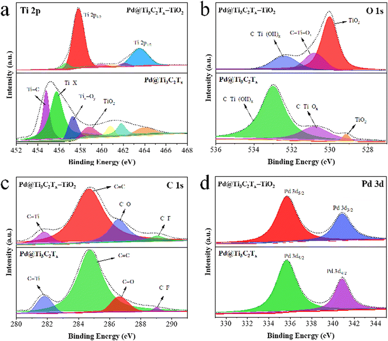
XPS was employed to examine the chemical composition and oxidation states of elements present in Pd@Ti3C2Tx and Pd@Ti3C2Tx–TiO2 catalysts (Fig. 6). The results confirm the existence of Ti, O, C, and with various terminal groups (i.e. Ti–C, Ti–X, Tix–Oy, C–Ti–(OH)x, C–Ti–Ox, C–F, C–O and C–Ti).80 To get deeper insights into the formation and terminal characteristics of Pd@Ti3C2Tx–TiO2 catalysts, individual analysis for Ti, O, Pd, and C was performed, and the results are shown in Fig. 6a–d. The Ti 2p peaks for Pd@Ti3C2Tx and Pd@Ti3C2Tx–TiO2 catalysts are illustrated in Fig. 6a; the Ti 2p3/2 peak in Pd@Ti3C2Tx have components at 454.78, 455.78, 457.28, and 458.98 eV, corresponding to Ti–C, Ti–X, Tix–Oy, and TiO2, respectively. In Pd@Ti3C2Tx–TiO2 catalysts, the TiO2 peak intensity has been increased while the intensity of other peaks has decreased, demonstrating the successful incorporation of Pd@Ti3C2Tx in TiO2 structures. Fig. 6b shows O 1s peaks for the Pd@Ti3C2Tx and Pd@Ti3C2Tx–TiO2 catalysts. The Pd@Ti3C2Tx cocatalyst exhibits C–Ti–(OH)x, C–Ti–Ox, and TiO2 peaks at binding energies of 532.98, 530.78, and 529.18 eV, respectively. The increase in the intensity of Ti–O bonds decreases in the C–Ti peak, confirming the successful fabrication of palladium on the Ti3C2Tx cocatalyst into TiO2.81 Numerous oxygen terminal groups were established during the conversion and transformations of cocatalysts. The C 1s spectrum shows four distinct peaks fitted at 281.78, 284.78, 286.68, and 289.08 eV, which were allocated to C–Ti, C![[double bond, length as m-dash]](https://www.rsc.org/images/entities/char_e001.gif) C, C–O, and C–F bonds, respectively (Fig. 6c). The C–Ti peak's intensity declines due to the conversion of surface and edge Ti-C bonds into Ti-O bonds. The peak locations of Pd 3d5/2 and Pd 3d3/2 are situated at 335.68 eV and 340.88 eV, respectively, as illustrated in Fig. 6d.82,83
C, C–O, and C–F bonds, respectively (Fig. 6c). The C–Ti peak's intensity declines due to the conversion of surface and edge Ti-C bonds into Ti-O bonds. The peak locations of Pd 3d5/2 and Pd 3d3/2 are situated at 335.68 eV and 340.88 eV, respectively, as illustrated in Fig. 6d.82,83
Optical properties
The UV-Vis/DRS results of TiO2, Ti3C2Tx, Ti3C2Tx–TiO2, and Pd@Ti3C2Tx–TiO2 catalysts are illustrated in Fig. 7a; TiO2 exhibits excellent absorption in the UV-region owing to its large bandgap (3.2 eV). Ti3C2Tx exhibits absorption throughout the entire UV-visible region due to its black colour, whereas the absence of an apparent absorption edge indicates its highly conductive nature.84 It has been found that in the case of Ti3C2Tx–TiO2 catalysts, Ti3C2Tx increases the absorption and impacts on the band edges. Thus, Ti3C2Tx expresses its ability for red shift (extended absorption) when it combines with TiO2. However, in comparison with Ti3C2Tx–TiO2 and Pd@Ti3C2Tx–TiO2, the presence of Pd metal resulted in further red shift.85 Moreover, due to inherent d-d transitions, Pd exhibits its absorption at 550 nm.86Fig. 7b illustrates the band gaps of TiO2, Ti3C2Tx–TiO2, and Pd@Ti3C2Tx–TiO2, which are 3.10 eV, 2.99 eV, and 2.95 eV, respectively.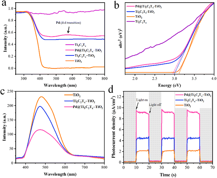 | ||
| Fig. 7 (a) The UV-vis/DRS and (b) energy diagram of TiO2, Ti3C2Tx, Ti3C2Tx–TiO2 and Pd@Ti3C2Tx–TiO2. (c) and (d) PL and photocurrent density of TiO2, Ti3C2Tx–TiO2, and Pd@Ti3C2Tx–TiO2. | ||
The photoluminescence (PL) results provide valuable insights about the excitations, charge traps, and transportations.87 The PL demonstrates the emission spectrum due to de-excitations in TiO2, Ti3C2Tx–TiO2, and Pd@Ti3C2Tx–TiO2.88 The result (indicated in Fig. 7c) for pristine TiO2 indicates the back reaction (higher recombination of photoexcited charges). However, Ti3C2Tx–TiO2 catalyst effectively reduces charge recombination by promoting the electron transfer to Ti3C2Tx surfaces.89 Meanwhile, the presence of Pd over Ti3C2Tx further enhances the charge transport and enhances the active sites. The comparison of PL results indicates that Pd@Ti3C2Tx–TiO2 delivers comparatively higher H2 production activities that are attributed to higher charge transfer.
The electrochemical measurements (i.e., photocurrent and EIS) were conducted to examine the dynamics of charge carrier generation, recombination, and charge transportation reactions.90 The photocurrent responses of Ti3C2Tx, Ti3C2Tx–TiO2, and Pd@Ti3C2Tx–TiO2 under on/off cycles were analyzed (Fig. 7d). The results clearly indicate that Pd@Ti3C2Tx–TiO2 photocatalysts exhibit higher photocurrent density compared to Ti3C2Tx–TiO2 and Pd@Ti3C2Tx–TiO2, which is linked with their stability and durability for photoreaction. These higher photocatalytic performances were attributed to the higher charge separation offered by Pd@Ti3C2Tx cocatalysts. The existence of Pd on the surfaces of MXene promotes the charge transfer dynamics. Moreover, the low Fermi level of Pd suppresses the recombinations between charges and promotes catalytic performances.11 The EIS studies further provide evidence about the effectiveness of cocatalysts. Comparatively, the smallest arc EIS radius of Pd@Ti3C2Tx–TiO2 as compared to Ti3C2Tx–TiO2 or pristine TiO2 indicates reduced interfacial charge resistance (Fig. 8a). Evidence obtained from PL, photocurrent, and EIS results are completely in accordance with higher hydrogen evolution performances of Pd@Ti3C2Tx–TiO2 catalysts.
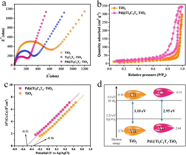 | ||
| Fig. 8 (a) EIS results of TiO2, Ti3C2Tx–TiO2 and Pd@Ti3C2Tx–TiO2. (b) BET results, (c) Mott–Schottky and (d) calculated band positions of TiO2 and Pd@Ti3C2Tx–TiO2. | ||
Surface area and electronic band structures
N2 adsorption–desorption study was carried out to examine the specific surface area of synthesised catalysts.91 The specific surface area of Pd@Ti3C2Tx–TiO2 was found (68.24 m2 g−1), which is greater than that of TiO2 (52.65 m2 g−1) (Fig. 8b). This increased surface area was attributed to the addition of Pd@Ti3C2Tx cocatalysts. Ti3C2Tx being a two-dimensional material contributes a relatively high surface. When Ti3C2Tx combined with TiO2, it increased the overall specific surface area92 of the composite material. Obviously, due to fabrication with MXene, the distribution of TiO2 particles increased; hence, the chances of agglomeration between TiO2 particles became quite low.Positions of the energy bands (i.e., VB and CB) of Pd@Ti3C2Tx–TiO2 and TiO2 catalysts were calculated using the Mott–Schottky (M–S) technique (Fig. 8c). The study clearly demonstrates that the flat-band potential of TiO2 was at −0.36 eV, whereas it is −0.51 eV for Pd@Ti3C2Tx–TiO2.93 The valence band positions were calculated with the help of UV-VIS/DRS and M–S techniques as reported,15 indicated by eqn (2) and Fig. 8d. It is worth mentioning that the M–S results were highly supportive in elucidating the electron transfer mechanism discussed in this work.
| EVB = ECB− EG | (2) |
E
CB and EVB represent the conduction as well as valence band potentials, respectively. The EVB values of TiO2 and Pd@Ti3C2Tx–TiO2 were calculated as 2.74 and 2.44![[thin space (1/6-em)]](https://www.rsc.org/images/entities/char_2009.gif) eV, respectively.94
eV, respectively.94
Comparative study of photocatalyst activities
The comparative H2 evolution rates of as-designed photocatalysts are illustrated in Fig. 9. The hydrogen evolution rate on pristine TiO2 (P25) was found to be 0.68 mmol g−1 h−1, which is considerably low due to the rapid recombination of charges. To enhance its photocatalytic performance, Ti3C2Tx was employed as a co-catalyst. In order to fix the optimal ratio of Ti3C2Tx over TiO2, various weight percentages, i.e., 2.5, 5, 7.5, and 10%, were designed. It was found that by increasing the Ti3C2Tx ratio, the H2 evolution rate remarkably increased. The maximum H2 evolution rate was observed with 7.5% Ti3C2Tx on TiO2, i.e., 12.04 mmol g−1 h−1 (see results in Table 1 and Fig. 9a). The improved activity was attributed to the lowering of Fermi levels for rapid electron transfer to active sites.95 Subsequently, a concentration of MXene higher than 7.5% causes a decline in the activities. This drawback was attributed to the blocking of light penetrations. To overcome this drawback, Pd metal was fabricated with Ti3C2Tx and then employed on a TiO2 support. The introduction of Pd@Ti3C2Tx on TiO2 progressively enhances the active sites where actual water reduction occurs. Because of the inherent higher work function,10,68 Pd quenches more electrons to utilize for water reduction reactions even in the absence of a sacrificial agent.96 In this work, 2% Pd with 7.5% Ti3C2Tx on TiO2 was found to be the most active catalyst that delivered 35.11 mmol g−1 h−1 of hydrogen (see results in Fig. 9b). Surprisingly, this activity is 50 times higher than bare TiO2. The higher activities on Pd@Ti3C2Tx–TiO2 compared to bare TiO2 were attributed to the higher electron transfer progress during the photoreactions. It has been found that in the absence of Pd@Ti3C2Tx cocatalyst, TiO2 is unable to resist the recombination of charges.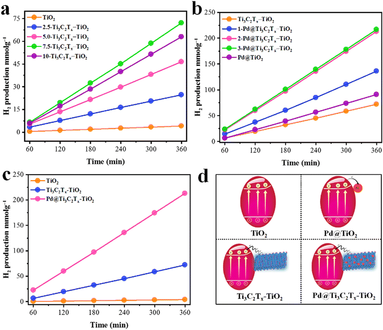 | ||
| Fig. 9 (a) Optimization of Ti3C2Tx over TiO2. (b) Optimization of Pd over Ti3C2Tx–TiO2; (c) comparison of optimised catalysts; (d) corresponding scheme of catalysts. | ||
| Sr. No. | Photocatalyst | Ti3C2Tx (wt%) | Pd (wt%) | H2 (mmol g−1) | H2 (mmol g−1h−1) | AQY (%) |
|---|---|---|---|---|---|---|
| 1 | TiO2 | 0 | 0 | 4.12 | 0.68 | 0.7 |
| 2 | 2.5-Ti3C2Tx–TiO2 | 2.5 | 0 | 24.69 | 4.11 | 4.19 |
| 3 | 5-Ti3C2Tx–TiO2 | 5.0 | 0 | 46.54 | 7.75 | 7.9 |
| 4 | 7.5-Ti3C2Tx–TiO2 | 7.5 | 0 | 72.24 | 12.04 | 12.6 |
| 5 | 10-Ti3C2Tx–TiO2 | 10 | 0 | 63.04 | 10.54 | 10.7 |
| 6 | Pd@TiO2 | 0 | 2.0 | 90.95 | 15.15 | 15.4 |
| 7 | 1-Pd@Ti3C2Tx–TiO2 | 7.5 | 1.0 | 134.16 | 22.35 | 22.8 |
| 8 | 2-Pd@Ti3C2Tx–TiO2 | 7.5 | 2.0 | 213.06 | 35.11 | 35.8 |
| 9 | 3-Pd@Ti3C2Tx–TiO2 | 7.5 | 3.0 | 216.88 | 36.14 | 36.8 |
The higher hydrogen evolution results justify the electron-promoting behaviour of Pd@Ti3C2Tx cocatalysts. The simultaneous enhancement of hydrogen evolution was attributed to the higher active sites available on Pd@Ti3C2Tx–TiO2 as compared to TiO2 and Ti3C2Tx–TiO2. The other important role of Pd is contributing to a higher work function during the photoreactions.97 Similarly, the effective role of MXenes has become prominent in the presence of Pd on TiO2 support. MXenes, due to their conducting nature, facilitate the more reactive and labile electrons available for anticipating the higher water reductions (i.e., more hydrogen evolution). To make this work more distinctive, hydrogen generation experiments were also done for Pd on TiO2 to elucidate the individual role of Titania and MXene. It has been found that Pd@TiO2 produces 15.15 mmol g−1 h−1 of hydrogen in the absence of MXene. The comparative performances of hydrogen generation on TiO2, Ti3C2Tx–TiO2, and Pd@Ti3C2Tx–TiO2 were evaluated in terms of mmol g−1, as depicted in Fig. 9c. The activities calculated in mmol g−1 h−1 are included in the supporting information section; See results in Fig. S1 (ESI†). The challenging task of this work was to affix the optimised ratio of the metal and MXene on TiO2, which is less common in the literature. The development and design of catalysts have proven to be a big advantage compared to other conventional catalysts utilized for water splitting.98 The comparison of related reported catalysts is tabulated in Table S1 (ESI†).
Recyclability
Monitoring of the recyclability of any catalysts is an important factor.99 This study emphasizes experiments to check the recyclability or reusability of as-designed and prepared catalysts. For the comparative study, Pd@Ti3C2Tx–TiO2 and Ti3C2Tx–TiO2 were chosen to perform the recyclability tests. It has been found that Pd@Ti3C2Tx–TiO2 catalysts show no significant loss in photoactivity (Fig S2, ESI†) after three cycles.100 Meanwhile, Ti3C2Tx–TiO2 exhibits a 22% loss in activity after three consecutive runs. The results obtained during the recyclability tests clearly demonstrate the stability of Pd@Ti3C2Tx–TiO2, which is higher than that of other catalysts of this project. The phase transformations, structural changes, and surface chemical states during the photoreaction were assessed through XRD and XPS analyses.96 It has been found that the XRD of Pd@Ti3C2Tx–TiO2 exhibits no phase transformations even after photoreactions (see results in Fig S3, ESI†). The XPS of the used Pd@Ti3C2Tx–TiO2 catalysts demonstrate that the oxidation states remain unchanged (illustrated in Fig S4, ESI†). Moreover, the MXene F-terminations have been reduced (i.e., replaced by −OH terminations during photoreactions).101 Surprisingly, the morphology of Ti3C2Tx–TiO2 was masked due to little loss of crystallinity (absence of metallic Pd site). The other reason is that due to the presence of Pd, more electrons were utilized for water reduction occurring on the metal centres. The extra stability was in accordance with the design of the catalyst, i.e., Pd@Ti3C2Tx–TiO2.Charge transportation and hydrogen evolution
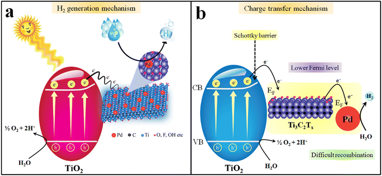
Insights into understanding the mechanism is one of the crucial factors for any photocatalytic process.102,103 It has been reported that the progress of a photocatalytic reaction depends upon the bandgap and redox potentials of catalysts.104 The bandgap of TiO2 and Pd@Ti3C2Tx–TiO2 were measured to be 3.10 eV and 2.95 eV, respectively (see UV-Vis/DRS results in Fig. 7b).105 The major drawback linked to TiO2 is its over potential and poor charge transportation ability, due to which it cannot control the back reaction between surface charges. When catalyst surfaces are exposed to light, the electrons are excited and move to the conduction band, leaving the holes at the valence band.106 However, by fabricating TiO2 with Ti3C2Tx, the transfer of charges towards active sites was significantly enhanced. Due to the conducting nature of Ti3C2Tx, TiO2 becomes more progressive for water reduction reactions.107 Thus, due to the higher charge conduction and transfer ability, MXene cocatalysts dramatically reduce the overpotential of TiO2. Another chemical property of MXene is the possession of lower Fermi levels compared to TiO2, which holds promise to lower the recombination of charges (i.e., back reaction between e−/h+). This lowering of charge recombination during photoreactions is responsible for higher catalytic performances. Fig. 10a elucidated the mechanism of hydrogen generation on Pd@Ti3C2Tx–TiO2. It has been found that Pd@Ti3C2Tx–TiO2 exhibits the highest rate of H2 production that is attributed to the presence of higher active sites.108 Note: it has been predicted that the presence of Pd@Ti3C2Tx at the interfaces of TiO2 acted as electron sinks to facilitate water reduction (i.e., redox sites) (see Fig. 10b). Moreover, it is worth mentioning that the work function of Pd@Ti3C2Tx is higher than TiO2. The higher work function of Pd@Ti3C2Tx led to the formation of a space charge layer between the interfaces (TiO2 and Pd@Ti3C2Tx cocatalysts) that causes alteration in the potentials for new energy bands (electron rich maxima) on a semiconductor.68,109 This alteration in the potentials enhances the developments of Schottky barriers during the photoreaction.110 These Schottky barriers hold promise to stop the backflow of electrons (recombination). The presence of Pd further promotes Schottky barriers to trap and transfer more electrons from the conduction bands and boost hydrogen generation reaction on metal active sites.45 Pd has the ability to quench the electrons and then release these electrons due to low electron affinities. Due to its high metallic character, Pd metal enhances the conductivity and electron transfer in the semiconductor system. Thus, the presence of Pd@Ti3C2Tx on the TiO2 system holds promise as a novel approach for researchers to design the catalysts for water-splitting reactions.Conclusions
In the current study, Pd@Ti3C2Tx–TiO2 photocatalysts were synthesized and employed for hydrogen generation reactions. The phase transformations from MAX (i.e., Ti3AlC2) to MXene (i.e., Ti3C2Tx 2D structures) were obtained by HF etching in a high-grade Teflon reactor (Techinistro/China). Reduction of Pd2+ to Pd0 on the Ti3C2Tx surfaces was successfully achieved without a reducing agent, i.e., in situ reduction by the interaction of localized/free electrons of Ti3C2Tx. The fabrication of Pd@Ti3C2Tx on TiO2 was achieved via in situ phase transformation reactions. The phase transformations from MAX to MXene were confirmed with XRD, FT-IR, SEM and XPS results. The chemical compositions and surface terminations of Pd@Ti3C2Tx–TiO2 were confirmed and evaluated with EDX and XPS analyses. The nature of the chemical bonding of catalysts was investigated via FT-IR and Raman spectroscopes. The presence of Pd on Ti3C2Tx was determined and confirmed using HRTEM. The electron traps and transfer from supports to the cocatalyst (Pd@Ti3C2Tx) were investigated via PL, EIS, and photocurrent results. Hydrogen generation activities were monitored on GC-TCD (Shimazdu-2010/Japan). The higher photocatalytic progress was attributed to the higher charge transfer, alteration in Fermi levels, and higher work function of cocatalysts. The ability of cocatalysts to effectively quench more electrons to promote and facilitate higher hydrogen generation has been investigated. In addition, the results depict that under similar conditions, Pd@Ti3C2Tx–TiO2 delivers higher hydrogen as compared to bare TiO2. Overall, 35.11 mmol g−1 h−1 of hydrogen was obtained on optimized catalysts (i.e., Pd@Ti3C2Tx–TiO2). Based on the results, it can be anticipated that fabrications of TiO2 with Pd@Ti3C2Tx cocatalysts hold promise as an attractive approach to designing new catalysts for hydrogen energy applications.Conflicts of interest
The author declares no competing financial interest.Acknowledgements
This work was financially supported by the Higher Education Commission of Pakistan award No. 377/IPFP-II/Batch-I/SRGP/NAHE/HEC/2020/27 and ASIP/R&D HEC/2023/5/22696/124 grants. Experimental work was conducted at the Institute of Chemistry, The Islamia University of Bahawalpur (Inorganic Material Laboratory (52s). Dr E.H. thanks the Carnegie Mellon University of USA for providing access to advanced instruments that were mandatory for catalyst characterizations.References
- F. Saleem, M. Z. Abid, K. Rafiq, A. Rauf, K. Ahmad, S. Iqbal, R. Jin and E. Hussain, Int. J. Hydrogen Energy, 2023, 52, 305–319 CrossRef.
- Q. Zhao, P. Yu, R. Mahendran, W. Huang, Y. Gao, Z. Yang, T. Ye, B. Wen, Y. Wu and S. Li, Eco-Environ. Health, 2022, 1, 53–62 CrossRef PubMed.
- S. Kanwal, M. T. Mehran, M. Hassan, M. Anwar, S. R. Naqvi and A. H. Khoja, Renewable Sustainable Energy Rev., 2022, 156, 111978 CrossRef CAS.
- D. Chen, H. Bai, J. Zhu, C. Wu, H. Zhao, D. Wu, J. Jiao, P. Ji and S. Mu, Adv. Energy Mater., 2023, 13, 2300499 CrossRef CAS.
- Q. Ma and S. Mu, Interdisciplinary Mater., 2023, 2, 53–90 CrossRef.
- Z. Ali, J. Ma, M. Hong and R. Sun, J. Mater. Chem. A, 2023, 11, 3297–3314 RSC.
- J. A. Nasir, Z. Ur Rehman, S. N. A. Shah, A. Khan, I. S. Butler and C. R. A. Catlow, J. Mater. Chem. A, 2020, 8, 20752–20780 RSC.
- U. Quyyum, K. Rafiq, M. Z. Abid, F. Ahmad, A. Rauf and E. Hussain, Environ. Sci.: Water Res. Technol., 2023, 9, 1147–1160 RSC.
- X. Ning and G. Lu, Nanoscale, 2020, 12, 1213–1223 RSC.
- E. Hussain, I. Majeed, M. A. Nadeem, A. Iqbal, Y. Chen, M. Choucair, R. Jin and M. A. Nadeem, J. Environ. Chem. Eng., 2019, 7, 102729 CrossRef CAS.
- E. Hussain, I. Majeed, M. A. Nadeem, A. Badshah, Y. Chen, M. A. Nadeem and R. Jin, J. Phys. Chem. C, 2016, 120, 17205–17213 CrossRef CAS.
- F. Mikaeili, T. Gilmore and P.-I. Gouma, Catalysts, 2022, 12, 1303 CrossRef CAS.
- S. Khan, V. Poliukhova, N. Tamir, J. Park, N. Suzuki, C. Terashima, K.-I. Katsumata and S.-H. Cho, Int. J. Hydrogen Energy, 2023, 48, 9713–9722 CrossRef CAS.
- M. Jalil, K. Rafiq, M. Z. Abid, A. Rauf, S. Wang, S. Iqbal and E. Hussain, Nanoscale Adv., 2023, 5, 3233–3246 RSC.
- A. Shahzad, K. Rafiq, M. Zeeshan Abid, N. Ahmad Khan, S. Shoaib Ahmad Shah, R. H. Althomali, A. Rauf and E. Hussain, J. Catal., 2024, 429, 115210 CrossRef CAS.
- M. Sabir, K. Rafiq, M. Z. Abid, U. Quyyum, S. S. A. Shah, M. Faizan, A. Rauf, S. Iqbal and E. Hussain, Fuel, 2023, 353, 129196 CrossRef CAS.
- N. Wajid, K. Rafiq, M. Z. Abid, A. Ilyas, T. Najam, A. Rauf and E. Hussain, Mater. Chem. Phys., 2023, 306, 128062 CrossRef CAS.
- P. Pattanayak, P. Singh, N. K. Bansal, M. Paul, H. Dixit, S. Porwal, S. Mishra and T. Singh, J. Environ. Chem. Eng., 2022, 108429 CrossRef CAS.
- A. Kumar, P. R. Thakur, G. Sharma, M. Naushad, A. Rana, G. T. Mola and F. J. Stadler, Environ. Chem. Lett., 2019, 17, 655–682 CrossRef CAS.
- R. Suresh, L. Gnanasekaran, S. Rajendran and M. Soto-Moscoso, Fuel, 2023, 348, 128528 CrossRef CAS.
- Y.-Y. Wang, Y.-X. Chen, T. Barakat, Y.-J. Zeng, J. Liu, S. Siffert and B.-L. Su, J. Energy Chem., 2022, 66, 529–559 CrossRef CAS.
- I. Majeed, U. Manzoor, F. K. Kanodarwala, M. A. Nadeem, E. Hussain, H. Ali, A. Badshah, J. A. Stride and M. A. Nadeem, Catal. Sci. Technol., 2018, 8, 1183–1193 RSC.
- A. Mishra, A. Mehta, S. Basu, N. P. Shetti, K. R. Reddy and T. M. Aminabhavi, Carbon, 2019, 149, 693–721 CrossRef CAS.
- K. Maeda, K. Teramura, D. Lu, N. Saito, Y. Inoue and K. Domen, Angew. Chem., 2006, 118, 7970–7973 CrossRef.
- X. Han, P. Liu, R. Ran, W. Wang, W. Zhou and Z. Shao, Mater. Today Energy, 2022, 23, 100896 CrossRef CAS.
- Y. Li, Y. Zhu, M. Wang, M. Zhao, J. Xue, J. Chen, T. Wu and S. A. Chambers, Adv. Funct. Mater., 2022, 32, 2203491 CrossRef CAS.
- X. Chen, B. Sun, Z. Han, Y. Wang, X. Han and P. Xu, Inorg. Chem. Front., 2022, 9, 4470–4477 RSC.
- X. Li, Y. Liu, P. Xu, X. Du, G. Mi, B. Mao and J. Zhang, Energy Fuels, 2022, 36, 2901–2909 CrossRef CAS.
- T. Su, Z. D. Hood, M. Naguib, L. Bai, S. Luo, C. M. Rouleau, I. N. Ivanov, H. Ji, Z. Qin and Z. Wu, ACS Appl. Energy Mater., 2019, 2, 4640–4651 CrossRef CAS.
- J. Yang, D. Wang, H. Han and C. Li, Acc. Chem. Res., 2013, 46, 1900–1909 CrossRef CAS PubMed.
- Q. Liu, X. Tan, S. Wang, F. Ma, H. Znad, Z. Shen, L. Liu and S. Liu, Environ. Sci.: Nano, 2019, 6, 3158–3169 RSC.
- I. Majeed, A. Idrees, A. Arif, W. Ashraf, S. Rasul, M. A. Khan, M. A. Nadeem and M. A. Nadeem, Energy Adv., 2022, 1, 842–867 RSC.
- S. Higashimoto, Y. Kurikawa, Y. Tanabe, T. Fukushima, A. Harada, M. Murata, Y. Sakata and H. Kobayashi, Appl. Catal., B, 2023, 325, 122289 CrossRef CAS.
- D. Chen and S. Mu, Energy Rev., 2023, 100053 CrossRef.
- P. Nayak, Q. Jiang, R. Mohanraman, D. Anjum, M. N. Hedhili and H. N. Alshareef, Nanoscale, 2018, 10, 17030–17037 RSC.
- K. Zhang, D. Li, H. Cao, Q. Zhu, C. Trapalis, P. Zhu, X. Gao and C. Wang, Chem. Eng. J., 2021, 424, 130340 CrossRef CAS.
- K. Huang, C. Li, H. Li, G. Ren, L. Wang, W. Wang and X. Meng, ACS Appl. Nano Mater., 2020, 3, 9581–9603 CrossRef CAS.
- Y. Wu, X. Li, H. Zhao, F. Yao, J. Cao, Z. Chen, X. Huang, D. Wang and Q. Yang, Chem. Eng. J., 2021, 418, 129296 CrossRef CAS.
- S. Zhao, H.-B. Zhang, J.-Q. Luo, Q.-W. Wang, B. Xu, S. Hong and Z.-Z. Yu, ACS Nano, 2018, 12, 11193–11202 CrossRef CAS PubMed.
- P. Liang, L. Yuan, K. Du, L. Wang, Z. Li, H. Deng, X. Wang, S.-Z. Luo and W. Shi, Chem. Eng. J., 2021, 420, 129831 CrossRef CAS.
- Y. Li, Y. Liu, D. Xing, J. Wang, L. Zheng, Z. Wang, P. Wang, Z. Zheng, H. Cheng and Y. Dai, Appl. Catal., B, 2021, 285, 119855 CrossRef CAS.
- J. He, J. Yang, F. Jiang, P. Liu and M. Zhu, Chemosphere, 2020, 258, 127339 CrossRef CAS PubMed.
- Y. Li, X. Deng, J. Tian, Z. Liang and H. Cui, Appl. Mater. Today, 2018, 13, 217–227 CrossRef.
- P. Lin, J. Shen, X. Yu, Q. Liu, D. Li and H. Tang, Ceram. Int., 2019, 45, 24656–24663 CrossRef CAS.
- G. Zeng, Y. Cao, Y. Wu, H. Yuan, B. Zhang, Y. Wang, H. Zeng and S. Huang, Appl. Mater. Today, 2021, 22, 100926 CrossRef.
- L. Liu, Q. Zhao, R. Liu and L. Zhu, Appl. Catal., B, 2019, 252, 198–204 CrossRef CAS.
- H. Park, P. R. Brown, V. Bulovic and J. Kong, Nano Lett., 2012, 12, 133–140 CrossRef CAS PubMed.
- B. Kim, S. H. Choi, X.-Y. Zhu and C. D. Frisbie, J. Am. Chem. Soc., 2011, 133, 19864–19877 CrossRef CAS PubMed.
- Z. Chen, S. Huang, B. Huang, M. Wan and N. Zhou, Appl. Surf. Sci., 2020, 509, 145319 CrossRef CAS.
- J.-X. Guo, S.-Y. Wu, G.-J. Zhang, L. Yan, J.-G. Hu and X.-Y. Li, J. Colloid Interface Sci., 2022, 616, 177–188 CrossRef CAS PubMed.
- T. Wang, X. Tao, X. Li, K. Zhang, S. Liu and B. Li, Small, 2021, 17, 2006255 CrossRef CAS PubMed.
- J. Xu, D. Gao, H. Yu, P. Wang, B. Zhu, L. Wang and J. Fan, Chin. J. Catal., 2022, 43, 215–225 CrossRef CAS.
- M. Naguib, M. Kurtoglu, V. Presser, J. Lu, J. Niu, M. Heon, L. Hultman, Y. Gogotsi and M. W. Barsoum, Adv. Mater., 2011, 23, 4248–4253 CrossRef CAS PubMed.
- C. Zhou, X. Wang, H. Luo, L. Deng, S. Wei, Y. Zheng, Q. Jia and J. Liu, Chem. Eng. J., 2020, 383, 123095 CrossRef CAS.
- Y. Tong, M. He, Y. Zhou, X. Zhong, L. Fan, T. Huang, Q. Liao and Y. Wang, Appl. Surf. Sci., 2018, 434, 283–293 CrossRef CAS.
- Y. Liu, Y.-H. Li, X. Li, Q. Zhang, H. Yu, X. Peng and F. Peng, ACS Nano, 2020, 14, 14181–14189 CrossRef CAS PubMed.
- R. Ricka, M. Přibyl and K. Kočí, Appl. Catal., A, 2023, 658, 119166 CrossRef CAS.
- M. Zhao and G. Zhang, Chem. - Asian J., 2023, 18, e202201108 CrossRef CAS PubMed.
- Y.-G. Yu, G. Chen, L.-X. Hao, Y.-S. Zhou, Y. Wang, J. Pei, J.-X. Sun and Z.-H. Han, Chem. Commun., 2013, 49, 10142–10144 RSC.
- J. Li, T. Xu, H. Bai, Z. Shen, Y. Huang, W. Xing and Z. Zhou, Adv. Mater. Interfaces, 2022, 9, 2101510 CrossRef CAS.
- S. Wang, Y. Liu, Y. Liu and W. Hu, Chem. Eng. J., 2023, 452, 139512 CrossRef CAS.
- P. Zhang, C. Fan, R. Wang, C. Xu, J. Cheng, L. Wang, Y. Lu and P. Luo, Nanotechnology, 2019, 31, 09LT01 CrossRef PubMed.
- Z. Bao, N. Bing, X. Zhu, H. Xie and W. Yu, Chem. Eng. J., 2021, 406, 126390 CrossRef CAS.
- N. Talreja, M. Ashfaq, D. Chauhan and R. Mangalaraja, Mater. Chem. Phys., 2023, 294, 127029 CrossRef CAS.
- H. An, T. Habib, S. Shah, H. Gao, M. Radovic, M. J. Green and J. L. Lutkenhaus, Sci. Adv., 2018, 4, eaaq0118 CrossRef PubMed.
- A. A. Ghani, B. Kim, M. Nawaz, K. C. Devarayapalli, Y. Lim, G. Kim and D. S. Lee, Chem. Eng. J., 2023, 467, 143473 CrossRef.
- M. Z. Abid, K. Rafiq, A. Rauf, S. S. Ahmad Shah, R. Jin and E. Hussain, Nanoscale Adv., 2023, 5, 3247–3259 RSC.
- E. Hussain, I. Majeed, M. A. Nadeem, A. Badshah, Y. Chen, M. A. Nadeem and R. Jin, J. Phys. Chem. C, 2016, 120, 17205–17213 CrossRef CAS.
- A. A. Ghani, A. Shahzad, M. Moztahida, K. Tahir, H. Jeon, B. Kim and D. S. Lee, Chem. Eng. J., 2021, 421, 127780 CrossRef.
- K. U. Sahar, K. Rafiq, M. Z. Abid, U. Rehman, U. Quyyum, A. Rauf and E. Hussain, J. Environ. Chem. Eng., 2023, 11, 111202 CrossRef CAS.
- V. Akshay, B. Arun, G. Mandal and M. Vasundhara, Phys. Chem. Chem. Phys., 2019, 21, 12991–13004 RSC.
- P. Panneerselvam, S. Ramasamy, S. P. Rajendra, M. S. AlSalhi, J. Guo and S. Angaiah, Adv. Mater. Technol., 2023, 2201551 CrossRef CAS.
- K. R. G. Lim, M. Shekhirev, B. C. Wyatt, B. Anasori, Y. Gogotsi and Z. W. Seh, Nat. Synth., 2022, 1, 601–614 CrossRef.
- T. Hou, Z. Jia, B. Wang, H. Li, X. Liu, L. Bi and G. Wu, Chem. Eng. J., 2021, 414, 128875 CrossRef CAS.
- N. B. Mullani, D. D. Kumbhar, D. H. Lee, M. J. Kwon, S. Y. Cho, N. Oh, E. T. Kim, T. D. Dongale, S. Y. Nam and J. H. Park, Adv. Funct. Mater., 2023, 2300343 CrossRef CAS.
- L. Chen, S. I. Allec, M.-T. Nguyen, L. Kovarik, A. S. Hoffman, J. Hong, D. Meira, H. Shi, S. R. Bare and V. A. Glezakou, J. Am. Chem. Soc., 2023, 145, 10847–10860 CrossRef CAS PubMed.
- G. Bharath, K. Rambabu, A. Hai, I. Othman, N. Ponpandian, F. Banat and P. L. Show, Chem. Eng. J., 2021, 414, 128869 CrossRef CAS.
- M. Z. Abid, A. Ilyas, K. Rafiq, A. Rauf, M. A. Nadeem, A. Waseem and E. Hussain, Environ. Sci.: Water Res. Technol., 2023, 9, 2238–2252 RSC.
- K. U. Sahar, K. Rafiq, M. Z. Abid, A. Rauf, U. Rehman, M. A. Nadeem, R. Jin and E. Hussain, Colloids Surf., A, 2023, 674, 131942 CrossRef CAS.
- Q. Yang and J. Hao, Colloids Surf., A, 2022, 633, 127848 CrossRef CAS.
- C. Peng, P. Wei, X. Li, Y. Liu, Y. Cao, H. Wang, H. Yu, F. Peng, L. Zhang and B. Zhang, Nano Energy, 2018, 53, 97–107 CrossRef CAS.
- E. Satheeshkumar, T. Makaryan, A. Melikyan, H. Minassian, Y. Gogotsi and M. Yoshimura, Sci. Rep., 2016, 6, 32049 CrossRef CAS PubMed.
- Z. Lang, Z. Zhuang, S. Li, L. Xia, Y. Zhao, Y. Zhao, C. Han and L. Zhou, ACS Appl. Mater. Interfaces, 2019, 12, 2400–2406 CrossRef.
- H. Wang, Y. Wu, T. Xiao, X. Yuan, G. Zeng, W. Tu, S. Wu, H. Y. Lee, Y. Z. Tan and J. W. Chew, Appl. Catal., B, 2018, 233, 213–225 CrossRef CAS.
- L. Cui, W. Zhu, Y. Xu and X. Qian, Anal. Chim. Acta, 2013, 786, 139–145 CrossRef CAS PubMed.
- Z. Mo, H. Xu, X. She, Y. Song, P. Yan, J. Yi, X. Zhu, Y. Lei, S. Yuan and H. Li, Appl. Surf. Sci., 2019, 467, 151–157 CrossRef.
- A. Aslam, M. Z. Abid, K. Rafiq, A. Rauf and E. Hussain, Sci. Rep., 2023, 13, 6306 CrossRef CAS PubMed.
- A. Bumajdad and M. Madkour, Phys. Chem. Chem. Phys., 2014, 16, 7146–7158 RSC.
- L. Yang, C. Dall'Agnese, Y. Dall'Agnese, G. Chen, Y. Gao, Y. Sanehira, A. K. Jena, X. F. Wang, Y. Gogotsi and T. Miyasaka, Adv. Funct. Mater., 2019, 29, 1905694 CrossRef CAS.
- X. Wu, F. E. Oropeza, Z. Qi, M. Einert, C. Tian, C. Maheu, K. Lv and J. P. Hofmann, Sustainable Energy Fuels, 2023, 7, 2923–2933 RSC.
- Q. Tao, M. Dahlqvist, J. Lu, S. Kota, R. Meshkian, J. Halim, J. Palisaitis, L. Hultman, M. W. Barsoum and P. O. Persson, Nat. Commun., 2017, 8, 14949 CrossRef PubMed.
- C. Yang, Q. Jiang, H. Liu, L. Yang, H. He, H. Huang and W. Li, J. Mater. Chem. A, 2021, 9, 15432–15440 RSC.
- C. Lai, B. Yan, R. Yuan, D. Chen, X. Wang, M. Wang, H. He and J. Tu, RSC Adv., 2023, 13, 16222–16229 RSC.
- S. Mirsadeghi, S. M. Ghoreishian, H. Zandavar, R. Behjatmanesh-Ardakani, E. Naghian, M. Ghoreishian, A. Mehrani, N. Abdolhoseinpoor, M. R. Ganjali, Y. S. Huh and S. M. Pourmortazavi, J. Environ. Chem. Eng., 2023, 11, 109106 CrossRef CAS.
- Q. Song, J. Hu, Y. Zhou, Q. Ye, X. Shi, D. Li and D. Jiang, J. Colloid Interface Sci., 2022, 623, 487–499 CrossRef CAS PubMed.
- K. U. Sahar, K. Rafiq, M. Z. Abid, U. Rehman, A. Rauf and E. Hussain, React. Chem. Eng., 2023, 8, 2522–2536 RSC.
- X. Ma, W. Li, C. Ren, M. Dong, L. Geng, H. Fan, Y. Li, H. Qiu and T. Wang, J. Colloid Interface Sci., 2022, 628, 368–377 CrossRef CAS PubMed.
- N. Zhao, Y. Hu, J. Du, G. Liu, B. Dong, Y. Yang, J. Peng, J. Li and M. Zhai, Appl. Surf. Sci., 2020, 530, 147247 CrossRef CAS.
- A. Ilyas, K. Rafiq, M. Z. Abid, A. Rauf and E. Hussain, RSC Adv., 2023, 13, 2379–2391 RSC.
- A. A. Khan, M. Tahir and A. Bafaqeer, Energy Fuels, 2020, 34, 9810–9828 CrossRef CAS.
- B. M. Abraham, P. Sinha, P. Halder and J. K. Singh, J. Mater. Chem. A, 2023, 11, 8091–8100 RSC.
- Q. Yang, L. Dong, R. Su, B. Hu, Z. Wang, Y. Jin, Y. Wang, F. Besenbacher and M. Dong, Appl. Mater. Today, 2019, 17, 159–182 CrossRef.
- N. Zhao, L. Kong, Y. Dong, G. Wang, X. Wu and P. Jiang, ACS Appl. Mater. Interfaces, 2018, 10, 9522–9531 CrossRef CAS PubMed.
- Y. AlSalka, O. Al-Madanat and A. Hakki, Appl. Catal., A, 2023, 119287 CrossRef CAS.
- T. Hou, Q. Li, Y. Zhang, W. Zhu, K. Yu, S. Wang, Q. Xu, S. Liang and L. Wang, Appl. Catal., B, 2020, 273, 119072 CrossRef CAS.
- A. H. Mady, M. A. Mahadadalkar, M. L. Baynosa, D. R. Kumar, A. M. Rabie, J. Lee, W. K. Kim and J.-J. Shim, J. Colloid Interface Sci., 2022, 606, 337–352 CrossRef PubMed.
- Y. Teja and M. Sakar, Small, 2023, 2303980 CrossRef CAS PubMed.
- G. Zuo, Y. Wang, W. L. Teo, A. Xie, Y. Guo, Y. Dai, W. Zhou, D. Jana, Q. Xian and W. Dong, Angew. Chem., 2020, 132, 11383–11388 CrossRef.
- M. U. Din, J. Munir, T. Alshahrani, H. Elsaeedy and Q. Ain, Mater. Sci. Semicond. Process., 2023, 163, 107569 CrossRef CAS.
- J. Kang, S. Byun, S. Kim, J. Lee, M. Jung, H. Hwang, T. W. Kim, S. H. Song and D. Lee, ACS Appl. Energy Mater., 2020, 3, 9226–9233 CrossRef CAS.
Footnote |
| † Electronic supplementary information (ESI) available. See DOI: https://doi.org/10.1039/d3ma00710c |
| This journal is © The Royal Society of Chemistry 2024 |

