
 Open Access Article
 This Open Access Article is licensed under a Creative Commons Attribution-Non Commercial 3.0 Unported Licence
Cu-based catalysts for electrocatalytic nitrate reduction to ammonia: fundamentals and recent advances
Kouer
Zhang
a,
Yun
Liu
a,
Zhefei
Pan
bc,
Qing
Xia
a,
Xiaoyu
Huo
a,
Oladapo Christopher
Esan
a,
Xiao
Zhang
*a and
Liang
An
 *ad
*ad
aDepartment of Mechanical Engineering, The Hong Kong Polytechnic University, Hung Hom, Kowloon, Hong Kong SAR, China. E-mail: xiao1.zhang@polyu.edu.hk; liang.an@polyu.edu.hk
bKey Laboratory of Low-Grade Energy Utilization Technologies and Systems (Chongqing University), Ministry of Education of China, Chongqing University, Chongqing 400044, China
cInstitute of Engineering Thermophysics, School of Energy and Power Engineering, Chongqing University, Chongqing 400044, China
dResearch Institute for Smart Energy, The Hong Kong Polytechnic University, Hun Hom, Kowloon, Hong Kong SAR, China
First published on 5th February 2024
Abstract
Electrocatalytic nitrate reduction has been identified as a promising technology for green ammonia production, allowing the conversion of harmful nitrate from wastewater into valuable ammonia using renewable electricity under ambient conditions. Developing advanced electrocatalysts is of paramount significance for improving the ammonia production efficiency in this process. Recently, Cu-based catalysts have been widely investigated in ammonia production via nitrate reduction due to their rapid reduction reaction kinetics, strong electrical conductivity, and ability to inhibit the hydrogen evolution reaction. Meanwhile, the reaction mechanism and computational and experimental methods have been extensively discussed to understand the theory behind the favourable properties of Cu-based catalysts. In this review, we focus on Cu-based catalysts, aiming to provide insights into the latest developments, reaction mechanisms, and state-of-the-art analysis methods for intermediates and products of nitrate reduction to ammonia. Future outlooks and remaining challenges are presented to provide guidance for advancing from experimental explorations to practical applications.
Broader contextThe global demand for ammonia is significantly increasing due to its significant industrial value and great potential as an energy carrier. However, traditional chemical methods utilized for ammonia production contribute to high energy consumption, hydrogen consumption, and greenhouse gas emissions. Electrochemical nitrate reduction, powered by renewable electricity under ambient conditions, has emerged as a promising alternative technology for green ammonia production. Despite its potential, the efficiency of ammonia production in this process remains relatively low. Thus, extensive efforts have been undertaken to develop efficient electrocatalysts that can overcome this limitation. Among various metal-based catalysts, Cu-based catalysts have demonstrated significant potential, primarily due to their occupancy of d orbitals that closely resemble the lowest unoccupied π* orbitals of nitrate. This unique characteristic facilitates accelerated electron transfer, leading to a reduced limiting potential and an expedited rate-determining step. In light of this, the present review aims to comprehensively explore the latest developments in Cu-based catalysts for electrocatalytic nitrate reduction to ammonia. This exploration will encompass an analysis of materials, elucidation of the underlying reaction mechanism, and evaluation of state-of-the-art analysis methods. By providing an up-to-date overview, this review ultimately intends to contribute to the advancement of future industrial implementations in this field. |
1. Introduction
As a globally important ingredient for industry (fertilizer, high-value chemicals, and pharmaceutical) and a next-generation energy carrier, ammonia (NH3) has long been widely utilized.1 In 2020, global ammonia demand reached 183 Mt with an expected increase of 20% in 2030.2 Moreover, the overall ammonia demand is estimated to increase 3-to-4-fold to 560–665 Mt in 2050.3 Invented in 1909 by German chemists Fritz Haber and Carl Bosch, the Haber–Bosch process has long been known as the most common but impactful ammonia production method.4 In this process, ammonia is produced through a thermocatalytic reaction of nitrogen and hydrogen, as expressed in the equation below:| N2(g) + 3H2(g) → 2NH3(g) ΔH = −92 kJ mol−1 | (1) |
![[triple bond, length as m-dash]](https://www.rsc.org/images/entities/char_e002.gif) N) and promote the reaction rate.5 It is worth mentioning that the hydrogen (grey hydrogen) consumed in the Haber–Bosch process is produced through steam reforming, which converts methane (CH4) to hydrogen and carbon monoxide (CO). This process requires high pressure (3–25 bar) and extremely high temperature (700–1000 °C).6 Thereafter, the carbon monoxide would undergo further treatment to be converted into carbon dioxide (CO2). It is reported that the Haber–Bosch process accounts for over 1% of global annual energy consumption and produces over 1.4% of global CO2 emission.7–9 Thus, tremendous efforts have been made to figure out an efficient and clean ammonia synthesis method. As a result, many alternative methods have been proposed in recent years, such as electrocatalysis, photocatalysis, heterogeneous catalysis, and nitrogenase enzyme catalysis.10,11
N) and promote the reaction rate.5 It is worth mentioning that the hydrogen (grey hydrogen) consumed in the Haber–Bosch process is produced through steam reforming, which converts methane (CH4) to hydrogen and carbon monoxide (CO). This process requires high pressure (3–25 bar) and extremely high temperature (700–1000 °C).6 Thereafter, the carbon monoxide would undergo further treatment to be converted into carbon dioxide (CO2). It is reported that the Haber–Bosch process accounts for over 1% of global annual energy consumption and produces over 1.4% of global CO2 emission.7–9 Thus, tremendous efforts have been made to figure out an efficient and clean ammonia synthesis method. As a result, many alternative methods have been proposed in recent years, such as electrocatalysis, photocatalysis, heterogeneous catalysis, and nitrogenase enzyme catalysis.10,11
Among them, electrocatalytic ammonia production in an aqueous system is currently a hot research area due to its potential for operating under ambient conditions, producing zero-emission, and using renewable energy as the driving force.12,13 With a flexible production scale, this method is suitable for combining intermittent renewable energy such as solar energy and wind energy.14 At first, researchers were interested in the nitrogen reduction reaction (NRR) due to its ability to directly utilize nitrogen and water. By utilizing water as an alternating hydrogen (H)-atom source, NRR avoids energy-intensive processes while solving the problem of hydrogen storage and transportation.15 Although this scenario is idealistic, the practical development of the NRR has long been impeded by low Faraday efficiency (FE, generally less than 10%) and a low ammonia yield rate (around 10−10 to 10−11 mol s−1).16 This value is far below the target proposed by the U.S. Department of Energy (DOE), which is an FE of over 90% and an ammonia yield rate of over 10−6 mol s−1.17 The poor performance of the NRR is mainly attributed to the inertness of N ≡ N and low N2 solubility in water (0.66 mmol L−1).18 Moreover, it has been reported that false positives exist in some works due to contaminants from the environment and inaccuracies in production tests.19
The employment of the nitrate reduction reaction (NO3RR) as a promising alternative to NRR for ammonia production is of great interest.20 Compared with NRR, in NO3RR, the solubility of nitrate (>2 mol L−1) is much higher than that of nitrogen while the disassociation energy of N = O (240 kJ mol−1) is much lower than that of N ≡ N (941 kJ mol−1).21,22 In addition, NO3RR is also an environmentally friendly nitrate degradation method as it converts harmful pollutants into valuable ammonia, realizing the concept of ‘turning waste into wealth’.23–25 However, the concerns regarding low product selectivity and sluggish reaction kinetics still exist, leading to unsatisfactory efficiency and impeding the further development of this method. To solve these problems, developing electrocatalysts with high activity and high selectivity is of top priority. Although precious metals and their alloys have been demonstrated to be effective for NO3RR, their application in ammonia production is limited due to their scarcity and high cost.23 Conversely, transition-metal catalysts have attracted much attention due to their adequate reserves and low cost. Besides, it is worth mentioning that the highly occupied d orbitals of some metals (Cu, Ag, Pt, etc.) are similar to the lowest unoccupied π* orbital of nitrate, which can accelerate electron transfer on these metals.24
Cu-based materials are one of the most promising types of catalysts for nitrate reduction and have been widely reported with superior performance recently.26 In general, Cu-based catalysts show the lowest limiting potential and the fastest rate-determining step, indicating excellent thermodynamic and kinetic activity.27,28 Furthermore, Cu-based catalysts have a weak ability for hydrogen evolution and outstanding selectivity towards ammonia production.29–31 These distinctive characteristics of Cu-based catalysts play a crucial role in enhancing the efficiency of electrocatalytic ammonia production, thereby underscoring the indispensable role of Cu in this field.
This review is primarily centered on Cu-based catalysts for the reduction of nitrate to ammonia, examining both the fundamental principles and methodologies involved. Although there exist numerous reviews on catalysts for nitrate reduction, only a limited number have specifically synthesized the mechanisms and corresponding evaluation methods for a distinct material type. Given the exponential growth in research outputs in this field, there is a pressing need for a comprehensive, up-to-date review that encapsulates recent advancements. This review aims to fill this gap, providing a valuable resource that offers insightful guidance for ongoing research in this field of study. The main structure of this review is illustrated below (Fig. 1).
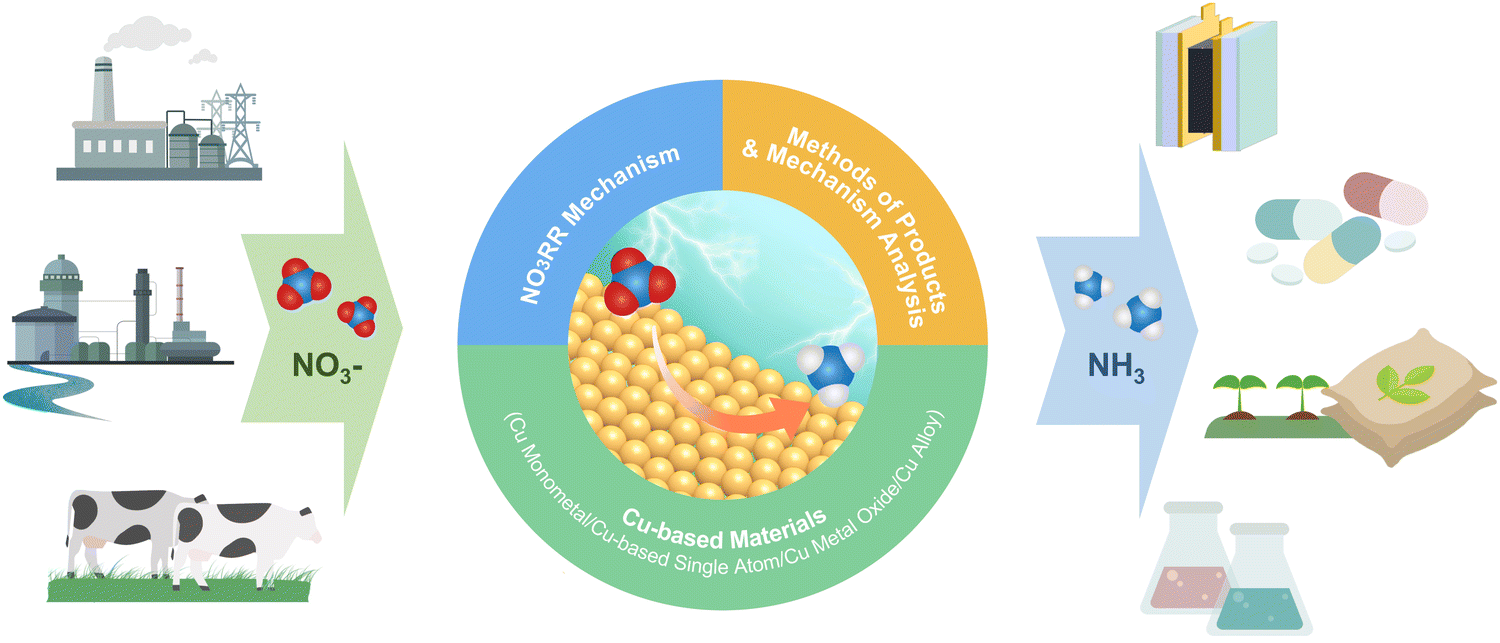 | ||
| Fig. 1 Schematic illustration of the nitrate reduction reaction towards ammonia synthesis. | ||
First, the reaction mechanism of NO3RR is discussed from the perspectives of reaction pathways and intermediates, activity criteria, and selectivity criteria on Cu-based electrocatalysts. In addition, the main challenges of nitrate reduction for ammonia production would be clarified. Second, different types of Cu-based materials for electrocatalytic ammonia production are introduced. Third, the analysis methods for electrocatalytic ammonia production used in product (ammonia) detection, the characterization of reactive intermediates and active species on the electrode surface are introduced. Finally, the application of Cu-based catalysts in electrocatalytic ammonia production via NO3RR and corresponding economic analysis are presented. The remaining challenges in the future development of NO3RR will be highlighted and future perspectives will be proposed.
2. Insights into the electrocatalytic mechanism
The development of efficient catalysts with excellent activity and selectivity is highly dependent on the in-depth understanding of the electrocatalytic mechanism. In this section, the reaction mechanism of NO3RR, including reaction pathways and intermediates, activity, and selectivity criteria, especially for Cu-based materials, will be described in detail as practical guidance for electrocatalyst design and selection.Before delving into the reaction pathways and intermediates of NO3RR, a general discussion of the working mechanism of NO3RR is presented on an electrode scale as shown in Fig. 2. First, the nitrate ions (NO3−) in the electrolyte migrate to the surface of the electrode, where they form absorbed nitrate (*NO3−). Then, the *NO3− ion combines with water molecules and electrons and the NO3RR takes place at the liquid–solid interface, converting *NO3− into absorbed ammonia (*NH3). The electrons, in this case, are provided by the external circuit and transferred through the electrode. After that, *NH3 desorbs from the surface, realizing the conversion from nitrate to ammonia. Generally, the NO3RR involves a series of deoxygenation steps from nitrate to *NO (or *N), followed by hydrogenation steps to produce ammonia. In each elementary step, hydrogen transfer occurs between hydrogen donors (*H) and acceptors (adsorbate).32 The kinetics of the NO3RR are strongly influenced by the nature of hydrogen transfer and the density of available hydrogen donors. However, if the *H recombine to form H2 through the HER pathway, it reduces the availability of *H for the subsequent steps of NO3RR and can limit the overall efficiency of ammonia production.
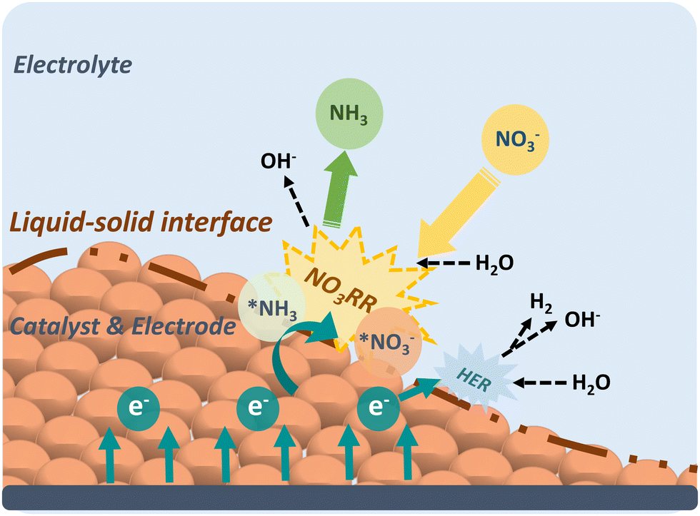 | ||
| Fig. 2 The schematic illustrating the NO3RR principle on an electrode-scale. | ||
Therefore, studying the mechanism of NO3RR is of utmost importance as it provides insights into the reaction pathway and enables the identification of strategies for regulating the process and minimizing the competing HER. A comprehensive understanding of the elementary steps involved in NO3RR, including the deoxygenation and hydrogenation steps, allows researchers to pinpoint the critical factors that influence the reaction kinetics and selectivity. This knowledge can then be utilized to design catalysts with tailored properties or modify reaction conditions to optimize the NO3RR process and mitigate the occurrence of the HER.
2.1. Reaction pathways and intermediates
With a broad span of valence states from NO3− to NH3 (ranging from +5 to −3), the conversion of nitrogen undergoes the complicated eight-electron transfer process involving a series of intermediates. In the whole process, intermediates such as NO2−ads, NOads, N2Oads, NHads, NH2ads, NH2OHads, etc. are involved between nitrate and ammonia. To better understand the mechanism, the reaction pathways and the intermediates of NO3RR should be identified under a thermodynamics framework.33 The overall reaction process of nitrate reduction towards ammonia could be presented in the form of an equation as shown below:34| NO3− + 6H2O + 8e− → NH3 + 9OH−, E0 = 0.88 V vs. RHE | (2.1) |
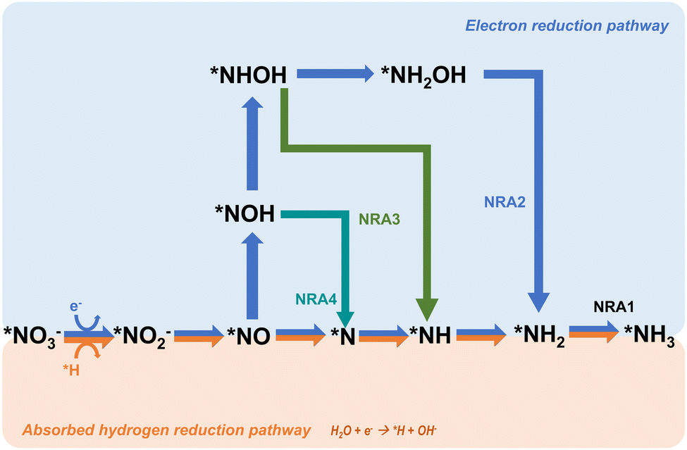
The mechanism in direct electrocatalytic reduction pathways is categorized into two parts based on the different mediation of the reaction, namely, absorbed hydrogen reduction and electron reduction. For the absorbed hydrogen reduction pathway, the reaction is regulated by the absorbed hydrogen atoms (*H) which are formed through the reduction of H2O (Volmer process) on the cathode surface.43 Then, the *H functions to reduce the NO3− ions to NH3 through a series of tandem reactions which are shown in the following equations proposed by Xu et al. (eqn (2.2)–(2.9)):44
| H2O + e− → *H + OH− | (2.2) |
| *NO3− + 2*H → *NO2− + H2O | (2.3) |
| *NO2− + *H → *NO + OH− | (2.4) |
| *NO → *N + *O | (2.5) |
| *N + *H → *NH | (2.6) |
| *NH + *H → *NH2 | (2.7) |
| *NH2 + *H → *NH3 | (2.8) |
| *NH3 → NH3 | (2.9) |
| *NO3− + H2O + 2e− → *NO2− + 2OH− | (2.10) |
| *NO2− + H2O + e− → *NO + OH− | (2.11) |
| *N + *N → N2 | (2.12) |
 | ||
| Fig. 3 The proposed direct electrocatalytic reduction pathways for nitrate reduction towards ammonia. | ||
Another common pathway, named NRA2 and shown in Fig. 2, involves the intermediate *NOH throughout the whole reaction.24,50,51 There are similar deoxygenation steps in these two pathways until the formation of NO*, and the main difference between these two pathways is the reaction sequence of hydrogenation and deoxygenation. Although these two pathways have been widely reported and reviewed, Hu et al. defined a more favourable pathway where deoxidation happens on *NHOH, forming *NH.33 This pathway is named NRA3. In Hu's work, all three pathways were evaluated on the commonly and stably exposed Cu (111) surface through density functional theory calculations under the defined condition of pH = 0. Gibbs free energies are regarded as a crucial factor in determining the spontaneity of a reaction and the key references in determining the reaction pathways. The results indicated that although NRA1 is more favourable in terms of thermodynamics, it exhibits sluggish kinetics with a higher energy barrier caused by the high activation energy (1.62 eV) of *NO → *N, which is 20 times higher than the activation energy (0.08 eV) of *NO → *NOH. Moreover, the activation energy (1.36 eV) of *NHOH → *NH2OH in NRA2 is much higher than the activation energy (0.23 eV) of *NHOH → *NH in NRA3. Besides, the intermediates in NRA2 tend to desorb more easily (such as hydroxylamine), thus forming more byproducts and causing side effects on the selectivity. Moreover, free Gibbs energies of each pathway under pH = 7 and 14 are considered as well. Taking all these factors into account, NRA3 was proved to be the most probable pathway in NO3RR over all pH ranges. Recently, Karamad et al. reported a pathway on Cu (111) similar to that in Hu's work,26 named NRA4 in this review. However, there are two intermediates different from those in the former NRA3 pathway as shown in Fig. 2. Particularly, the intermediates involved in deoxidation from *NOH to *NH differ between the two pathways, where *N is formed due to the reduction of *NO. Despite the slight differences in pathways, the potential limiting step remains the hydrogenation from *NO to *NOH.
Based on the NRA3 pathway, which is regarded as the most favourable pathway, the pH effects on the Gibbs free energies of the most typical Cu (111) surface are evaluated.33 As shown in Fig. 4, at pH = 0, the rate-determining step is the desorption of *NH3, which needs 0.37 eV in NRA3. However, under neutral conditions of pH = 7, the rate-determining step becomes the hydrogenation process *NO → *NOH with a free energy barrier of 0.50 eV. At pH = 14, the rate-determining step still occurs during this hydrogenation process with a higher Gibbs free energy of 0.91 eV. Speculated from the calculation results, the NO3RR process is more energetically favourable at higher H+ concentrations (lower pH values). Meanwhile, the competition between the NO3RR and HER is considered as well under the above three pH conditions. Under acidic conditions, the rate-determining step of HER is the formation of H2 (ΔGRDS = 0.25 eV), of which the Gibbs energy is lower than that in NO3RR, suggesting the inferior NO3RR performance due to the strong HER. Under neutral and alkaline conditions, the cases are different: the rate-determining step of the HER is H+ → *H, with Gibbs free energies of 0.58 eV and 1.14 eV, respectively. Both these values are higher than the corresponding ΔGRDS of the NO3RR process, indicating the improved selectivity towards ammonia with suppressed HER. To sum up, at a higher concentration of H+, the energy barriers would be lower for both NO3RR and HER. However, it is important to consider the competitive relationship between these two reactions when determining the optimal pH value for the NO3RR and thus the selectivity for ammonia synthesis can be maximized.
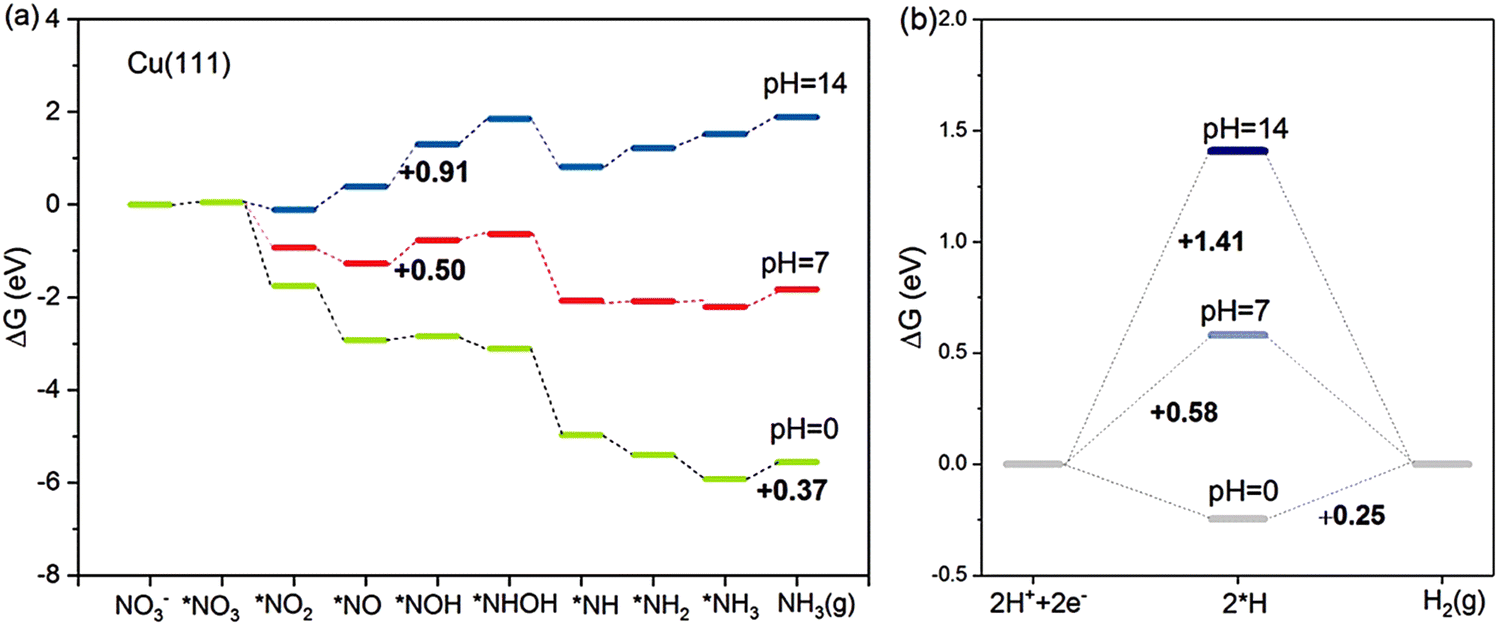 | ||
| Fig. 4 The competition between (a) NO3RR and (b) HER on Cu (111) at pH = 0, 7 and 14, studied by Hu et al. Reprinted with permission from ref. 33. Copyright 2021, American Chemical Society. | ||
2.2. Activity criteria
Activity is of primary importance in judging a specific catalyst and serves as a valuable guideline for developing a new catalyst. In general, for a particular catalyst, the catalytic activity for a reaction is decided by the applied potential and the adsorption strength of intermediates, affecting the concentration of both reactants and intermediates.49 In the NO3RR, the adsorption energies of the nitrogen atom and oxygen atom have direct impacts on the activities while the relationship between the maximum activity and the adsorption energies of a specific material is also controlled by the applied potential.Liu et al. investigated the activities of different transition metals (Cu, Co, Rh, Pd, Ag, and Pt) at different applied potentials (−0.2 V, 0 V, 0.2 V, and 0.4 V vs. reversible hydrogen electrode (RHE)) through computational mean-field microkinetic modelling based on density-functional theory (DFT).52–55 As shown in Fig. 4, the theoretical volcano plot of turnover frequencies (TOF) is constructed as a function of atomic oxygen and nitrogen adsorption energies. Comparing the maximum activities based on theoretical simulations, Cu has the highest activity in NO3RR among non-noble metal catalysts, which is in accordance with the former report based on experiments.29 Calculation of limiting potential steps is another approach for estimating the catalytic activities of metal.26 As reported by Karamad et al., the limiting potential step for Cu is *NO–*NOH with the corresponding limiting potentials of −0.23 V vs. RHE. Through comparison, it can be demonstrated that Cu is the most active among non-noble metal catalysts for NO3RR.
2.3. Selectivity criteria
Selectivity is another principal factor that should not be neglected in designing efficient electrocatalysts. As a reaction with complicated reaction pathways, various byproducts can be generated during the NO3RR process such as N2, N2O, NO, etc.35 Similarly, both the adsorption energies (ΔEO and ΔEN) and the applied potential have great impacts on the selectivity towards products.52 As shown in Fig. 5, generally, with more negative potentials, NH3 production would be promoted, whereas more positive potentials would promote selectivity towards N2, which is in accordance with the higher standard electrode potential (E0 = 1.25 V vs. RHE) in N2 production. Meanwhile, the formation of N2 requires strong adsorption energies for both atomic N and O while the formation of NH3 prefers relatively moderate ΔEO and ΔEN. Consequently, Cu has the best selectivity towards ammonia in the NO3RR among non-noble metals (Fig. 6).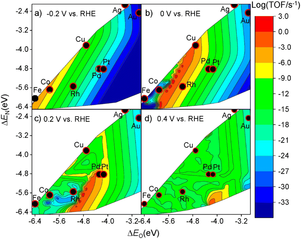 | ||
| Fig. 5 Theoretical volcano plots of the TOF as a function of atomic oxygen (ΔEO) and nitrogen (ΔEN) adsorption energies for electrocatalytic nitrate reduction on transition metal surfaces based on DFT-based microkinetic simulations at (a) −0.2 V, (b) 0 V, (c) 0.2 V, and (d) 0.4 V vs. RHE by Liu et al. Reprinted with permission from ref. 52. Copyright 2019, American Chemical Society. | ||
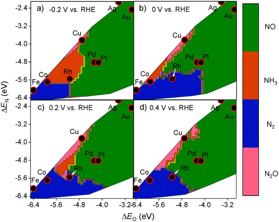 | ||
| Fig. 6 Theoretical selectivity maps to NO, N2O, N2, or NH3 products from electrocatalytic nitrate reduction as a function of oxygen and nitrogen adsorption energy at (a) −0.2 V, (b) 0 V, (c) 0.2 V, and (d) 0.4 V vs. RHE by Liu et al. Reprinted with permission from ref. 52. Copyright 2019, American Chemical Society. | ||
Apart from the formation of byproducts, the hydrogen reduction reaction (HER) is a strong competitive reaction against NO3RR under negative potentials. In this regard, the evaluation of NO3RR selectivity over HER is a key evaluation criterion. It has been reported that the binding energy of *H is a reasonable descriptor for the activity of HER.56,57 To clarify the selectivity tendency towards HER or NO3RR, Karamad et al. studied the relationship between the limiting potentials for HER and NO3RR on various transition metals.58 As shown in Fig. 7, UL(NO3RR) − UL(H2) represents the selectivity tendency for NO3RR over HER, while UL(NO3RR) reflects the activity tendency of NO3RR. The most effective catalysts appear in the upper right corner of the figure. In conclusion, Cu is suggested to be the most active and selective transition metal catalyst for NO3RR, making Cu-based materials promising for nitrate reduction towards ammonia.
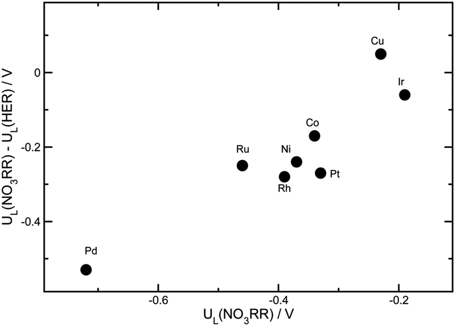 | ||
| Fig. 7 The differences between the limiting potentials for the NO3RR and HER by Xu et al. Reprinted with permission from ref. 26. Copyright Royal Society of Chemistry. | ||
In conclusion, with the great interest in Cu-based electrocatalysts for NO3RR, many works investigating the mechanism insights into Cu-catalyzed-NO3RR have been reported through theoretical calculations. Various pathways of NO3RR have been proposed with no definitive conclusion although the previously discussed NRA3 route is regarded more favorable on Cu. Besides, the activity and selectivity of Cu-based materials have been proven from the perspective of the underlying mechanism.
3. Cu-based materials
NO3RR is a promising electrocatalytic reaction of ammonia production. However, the complex electronic pathways of NO3RR to ammonia require highly active and selective electrocatalysts to counteract other competing reactions, of which HER is the most prominent. During the last few decades, various electrocatalysts have been reported to have excellent performance in the electrochemical synthesis of ammonia.59–61 Among them, transition metal-based catalysts, which have the unique electronic structure of partially filled d-orbitals, can easily donate and accept electrons from other molecules, therefore achieving the strong absorption of electron-rich nitrogen atoms.62 Meanwhile, the transition metal-based catalysts have the potential to inhibit the competing HER and raise the energy barriers for the by-products, thus promoting the FE of NO3RR and the selectivity towards ammonia.45 Besides, it has been demonstrated that the electron transfer can be accelerated due to the close energy levels between the highly occupied d-orbitals (HOMOs) and the lowest empty π-orbitals (LOMOs) of the transition metal-based catalysts.24 Following these considerations, transition metal-based electrocatalysts have been extensively studied and reported as promising catalysts for electrochemical ammonia synthesis.20,63,64The first reported Cu electrocatalyst for nitrate reduction was developed in 1979 by Pletcher and Poorabedi.65 In this work, the Cu disc working electrode acted as a catalyst in acidic perchlorate and sulfate as media, confirming the feasibility of nitrate reduction to ammonia through the electrochemical pathway. However, in the next several decades, only a limited number of works were reported because of the low FE and ammonia yield, which made this method of ammonia production seem worthless compared to biological and industrial methods.19,66–68 It was not until recent years that the field of electrochemical ammonia synthesis attracted the interest of researchers again due to the increasing demand for green ammonia with the aim of carbon neutrality. Besides, along with the outstanding advances in nanomaterial synthesis and characterization methods, many newly designed electrocatalysts have been reported since then.
To date, a large number of noble metal catalysts such as Ru, Rh, Pt, Pd, Au, etc. as well as their bimetallic and other novel structures/morphologies have been extensively investigated, showing satisfactory performance, including low overpotential which means limited energy consumption, high FE and ammonia yield rate.69–77 However, the high cost and low reserves of noble metals limit their potential for large-scale industrial applications. As a result, the non-noble transition metal catalysts, which not only have relatively low cost and abundant sources but also demonstrate comparable activity for the electrochemical synthesis of ammonia, have attracted considerable interest from researchers.78–81
Among these noble metal-free catalysts, Cu and Cu-based materials are promising candidates for NO3RR and even show better selectivity and activity than many noble metal catalysts, which has been proven through the comprehensive evaluation of both experimental results and computational theoretical analysis.26 To achieve ideal product selectivity and reaction kinetics, there has been a tremendous interest in developing advanced Cu-based electrocatalysts for NO3RR via tuning the Cu active site through various strategies such as crystal facet engineering, electronic and geometric tuning, alloying and doping modifications, single atom dispersion strategies.82–84 In addition, the design of copper-based catalysts involves careful selection and engineering of support materials to enhance their catalytic performance. This comprises the use of specific support materials with specific surface properties, porosity and electronic interactions with copper species.
In this section, the Cu-based materials functioning as electrocatalysts in the nitrate reduction reaction for ammonia production will be catalogued and introduced individually. The table below summarizes the state-of-the-art electrochemical performances of Cu-based materials in the NO3RR (Table 1).
| Material-type | Name | Potential | FE (%) | Yield | Electrolyte | Ref. |
|---|---|---|---|---|---|---|
| Cu monometal | Cu disc | −0.55 V vs. SCE | 68 | N/A | 1.0 M HClO4 and 5 mM NO3− | 65 |
| Cu nanosheet | −0.15 V vs. RHE | 99.7 | 0.39 mg mgCu−1 h−1 | 0.1 M KOH and 10 mM KNO3 | 82 | |
| Cu nanodisk | −0.5 V vs. RHE | 81.1 | 2.16 mg mgCu−1 h−1 | 0.1 M KOH and 10 mM KNO3 | 85 | |
| Cu single atom | Cu(I)–N3C1 | −0.64 V vs. RHE | 65.3 | 76.52 mg g−1Cu h−1 | 50 mM Na2SO4 and 7.1 mM NaNO3 | 86 |
| Cu–N–C SAC | −1.0 V vs. RHE | 84.7 | 212.5 mg g−1Cu h−1 | 0.1 M KOH and 0.1 M KNO3 | 87 | |
| Cu–N–C | −1.5 V vs. SCE | 94 | 9.23 mg g−1Cu h−1 | 0.5 M Na2SO4 and 3.6 mM NaNO3 | 88 | |
| Cu oxide | Cu@Cu2+1O NWs | −1.2 V vs. SCE | 78.57 | 0.58 mg g−1Cu h−1 | 0.5 M K2SO4 and 7.1 mM KNO3 | 48 |
| Cu2O | −0.8 V vs. RHE | 92.28 | N/A | 0.5 M Na2SO4 and 5.0 mM NaNO3 | 89 | |
| Cu2O (100) facets | −0.6 V vs. RHE | 82.3 | 0.74 mg g−1Cu h−1 | 0.1 M Na2SO4 and 3.6 mM NaNO3 | 90 | |
| Cu2O–OV | −1.1 V vs. Ag/AgCl | 89.54 | 1.40 mg−1 cm−2 h−1 | 0.5 M Na2SO4 and 3.2 mM NO3− | 91 | |
| Cu alloy | Ru–Cu NW | −0.13 V vs. RHE (1 A cm−2) | 90 | 76.5 mg cm−2 h−1 | 1.0 M KOH and 32.3 mM KNO3 | 77 |
| CuCo nanosheets | −0.2 V vs. RHE (1035 mA cm−2) | 100 | 0.96 mg g−1Cu h−1 | 1.0 M KOH and 100 mM KNO3 | 92 | |
| Au1Cu (111) | −0.2 V vs. RHE | 97 | 0.55 mg cm−2 h−1 | 0.1 M KOH and 7.1 mM KNO3 | 93 | |
| Cu49Fe1 | −0.7 V vs. RHE | 94.5 | 3.91 mg cm−2 h−1 | 0.1 M K2SO4 and 3.2 mM KNO3 | 94 | |
| Cu50Ni50 | −0.15 V vs. RHE | 99 | N/A | 1.0 M KOH and 0.1 M KNO3 | 74 | |
| Rh@Cu | −0.2 V vs. RHE | 93 | 21.59 mg cm−2 h−1 | 0.1 M Na2SO4 and 0.1 M NaNO3 | 83 | |
| 10Cu/TiO2−x | −0.75 V vs. RHE | 81.34 | 1.94 mg cm−2 h−1 | 0.5 M Na2SO4 and 3.2 mM NaNO3 | 95 |
3.1. Cu monometal
As early as 1979, a Cu disc was used as the cathode in aqueous acidic perchlorate and sulphate media for the first time.65 The experiments revealed that nitrate ions could be eventually reduced to ammonia if sufficient protons were provided in the reaction. The authors also proposed that the nitrate reduction is sensitive to the reaction condition, especially the electrode materials. Although the experimental and characterization methods were relatively poor compared to the present technology, this work did provide significant inspiration for further research on copper-based electrocatalysts at that time.Owing to the rapid development of nanotechnology, even monometallic materials have given rise to numerous fine-structure catalysts. When Cu is minimized down to the nanometer scale in one or several directions, the motion of electrons in this direction is subjected to confinement, which triggers a transition in the properties of the material and has a profound effect on the catalytic performance.96 For example, Fu et al. reported a Cu nanosheet catalyst for nitrate reduction to ammonia with extremely high ammonia selectivity.82 The FE reached a record-high value of 99.7% FE at −0.15 V vs. RHE, with an ammonia yield rate of 390.1 μg mgCu−1 h−1, which was over 400 times higher than that of bulk Cu foil. The outstanding performance could be attributed to the suppressed HER and increase in the current density of the rate-determining step, namely, nitrite generation (S1) in this reaction. It is worth mentioning that the authors analyzed the reduction peaks exhibited on the LSV curves corresponding to four different reaction processes (S1, S2, S3, and S4) as shown in Fig. 8.82,97,98 The equations/processes of the reactions are given below (eqn (3.1)–(3.3)):
| S1: NO3− + H2O + 2e− → NO2− + 2OH− | (3.1) |
| S2: NO2− + 4H2O + 4e− → NH2OH + 5OH− | (3.2) |
| S3: NO2− + 5H2O + 6e− → NH3 + 7OH− | (3.3) |
| S4: competing adsorption (Had) of the intermediate N–species |
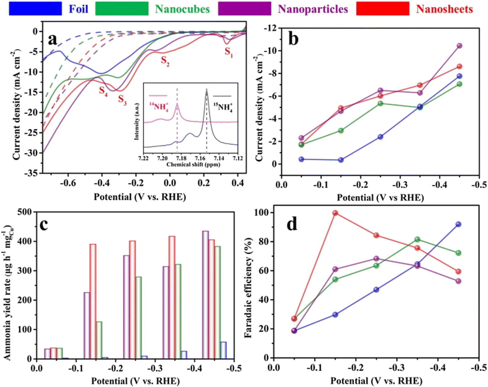 | ||
| Fig. 8 Electroreduction of nitrate to ammonia on the copper catalyst. (a) Linear sweep voltammetry curves of copper catalysts on carbon paper measured in 0.1 M KOH (dotted line) in the presence of 10 mM KNO3 (solid line). Scan rate: 20 mV s−1. (b) Current densities, (c) ammonia yield rates and (d) Faradaic efficiencies of various Cu catalysts for ammonia production at different applied potentials. Preprinted with permission from ref. 76. Copyright 2020 Elsevier Ltd. | ||
It was noteworthy that the ammonia yield rate was confirmed using both 1H nuclear magnetic resonance (NMR) spectra and the regular indophenol-blue method through ultraviolet-visible (UV-vis) spectroscopy, improving the data reliability.16 The details of the methods will be introduced in later sections. Since Cu (111) was reconstructed from the oxidation state of copper, the perfect Cu (111) surface was compared with the reconstructed Cu (111) surface in the investigation of catalytic mechanisms through DFT calculations. It could be concluded that the surface triatomic Cu clusters formed in the reconstruction weakened the interaction of N–O bonds and exhibited better absorption of NO3−, hence improving the NO3RR performance to a practical standard. Besides, when the size of Cu is minimized, it can be reduced to the ultimate form of nanoparticles – Cu single atoms, which exhibit unique electronic structures that maximize atomic utilization.99 The specific discussion on this type of electrocatalyst will be addressed in a later section.
Furthermore, recent studies have also explored facet tandem catalysis using Cu monometal catalysts. By modifying the Cu (100) and Cu (111) facets, a tandem catalysis system is created (Fig. 9), where nitrite is generated on the Cu (100) facet and subsequently hydrogenated on the Cu (111) facet.100 This tandem catalysis mechanism is achieved through crystal face engineering and has demonstrated high-performance NO3RR with an ammonia yield rate of 1.41 mmol h−1 cm−2 at −0.59 V vs. RHE, and excellent stability over 700 hours.
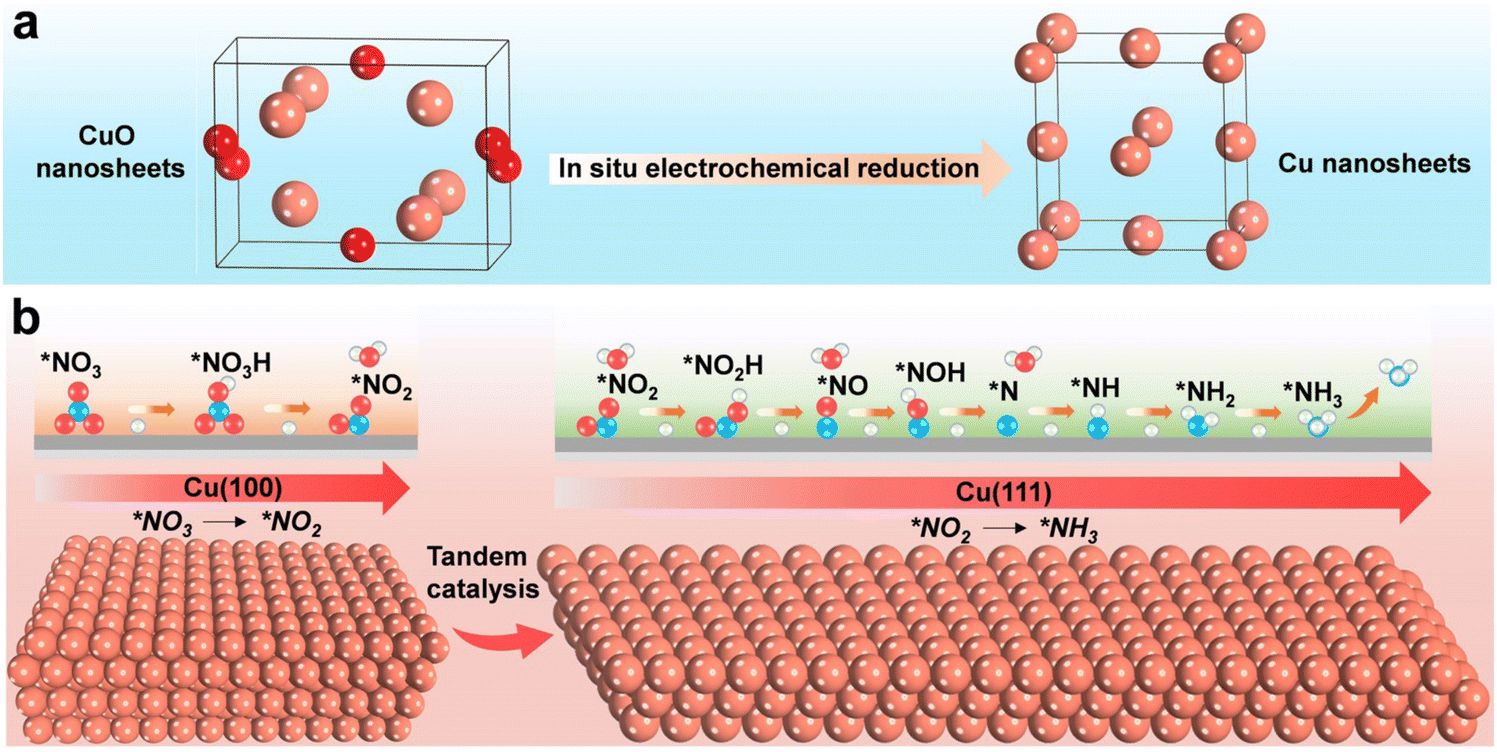 | ||
| Fig. 9 Schematic illustration for enhancing the electrochemical NO3RR over Cu nanosheets via tandem catalysis. (a) Electrochemical in situ reduction of the as-prepared CuO nanosheets during NO3RR. (b) Tandem interaction of Cu (100) and Cu (111) facets. Reprinted with permission from ref. 100. Copyright 2023 Wiley-VCH Verlag GmbH. | ||
3.2. Cu single atoms
Although bulk Cu metallic catalysts have been widely investigated in the nitrate reduction reaction for ammonia production, it still suffers from low stability and activity, especially after long-term operation.50,97 According to previous research, there are two issues related to this unsatisfactory performance, which are catalyst deactivation caused by corrosion and nitrite poisoning.61 To overcome these limitations, minimizing the size of Cu nanoparticles to a single-atom level is a promising strategy for Cu-based catalysis of NO3RR. Single-atom catalysts offer prominent advantages in terms of extremely high utilization efficiency and unique catalytic performance compared to their bulk materials.100–102 Specifically, several highlights attributing to these advantages are listed below: (1) adequately exposed active sites facilitate strong adhesion and conversion of the reactants, leading to better activity; (2) homogeneous active sites and structures allow uniform interaction between active sites and substrates, leading to better selectivity; and (3) the strong interactions between single atoms and coordination atoms stabilize the single metal atoms, leading to a better stability.103,104 Thus, using single atoms as catalysts has been a new frontier in the electrochemical catalysis area and several works have reported Cu single-atom catalysts for ammonia production through NO3RR.87,88,105For instance, Zhu et al. reported a metal–nitrogen–carbon (M–N–C) catalyst with Cu single atoms embedded into the nitrogenated carbon nanosheet (Cu–N–C), exhibiting extraordinary activity, selectivity, and stability in nitrate reduction reaction.104,105 The Cu–N–C single-atom catalyst was synthesized through pyrolysis of Cu-MOFs as a precursor in an Ar atmosphere. Also, the effect of annealing temperature on the size of Cu nanoparticles/atoms on the nanosheet was studied, revealing that increasing temperature resulted in the aggregation of Cu atoms. It iss worth mentioning that when the annealing temperature was lower than 800 °C, the Cu atoms were not exposed, but covered with a thick layer of carbon. The formation of Cu single atoms at 800 °C was confirmed through high-angle annular dark-field scanning transmission electron microscopy (HAADF-STEM) images, XRD, X-ray absorption near edge structure (XANES) and extended X-ray absorption fine structure (EXAFS). In this catalyst, Cu existed in the form of Cu(I) and Cu(II) due to the formation of Cu–N4 and Cu–N2. Cu(0) was not observed until the formation of Cu nanoparticles, as shown in Fig. 8. As a critical factor for electrocatalyst development, the outstanding stability of the Cu–N–C single-atom catalyst was clarified. Compared to Cu–N–C nanoparticles (pyrolysis temperature of 900 °C/1000 °C), it maintained a superior electrocatalytic performance with only 5.4% declination after 20 consecutive cycles. Moreover, through both experimental methods and theoretical calculations, the Cu–N–C single atom catalyst was proved to alleviate the nitrite production and accumulation compared to other bulk Cu catalysts, addressing a critical issue of Cu-based catalysts in NO3RR.
Yang et al. also reported Cu–N–C SAC for nitrate reduction to ammonia with a high Faradaic efficiency of 84.7% at −1.00 V (vs. RHE) and an ammonia yield rate of 4.5 mg cm−2 h−1.87 The synthesized catalyst featured a mesoporous structure and a large specific area of 1065 m2 g−1. In Cu–N–C SAC, the concentration of Cu was determined to be 1.0 wt%, and the content of N was 10.23 at%. The authors also revealed another mechanism of Cu–N–C, in which the Cu single atoms would reconstruct into nanoparticles during the electrochemical reduction process. The valence state of fresh Cu–N–C SAC was Cu(I) in the form of Cu–N4. However, in the nitrate reduction reaction process, Cu(I) was also reduced and aggregated into metallic Cu, which could be figured out in HAADF-STEM images. After the electrolysis, the aggregation of Cu0 nanoparticles would disintegrate reversibly and be stored in the Cu–N4 structure again after reoxidation in air. Besides, operando XAS and density functional theory calculations were also applied in the study to unveil the dynamic evolution of the Cu–Nx structure.
Most recently, Li et al. systematically unveiled the size effect of the Cu-based catalyst in NO3RR.99 Aiming at the study of size effects, the authors tailored the Cu-based catalyst ranging from single-atom catalysts to single-cluster catalysts and nanoparticles. The study revealed the effect of size and the coordination environment on the high catalytic activity and selectivity for the NO3RR and suggested a promising design strategy for size-controlled aerogel-based catalysts for various electrocatalytic reactions.
3.3. Cu metal oxide
Metal oxides are another major class of metal catalysts with various surface morphologies and compositions. Transition metal oxides occupy an important position in the catalysis field and contribute to relatively high catalytic activity. Among them, Cu metal oxides have been proven to be one of the most effective catalysts for electrochemical ammonia production.Alongside the direct formation of Cu metal oxides during the synthesis process, copper-based materials may undergo phase changes during the electrocatalysis process, forming copper metal oxides with different surfaces and compositions, resulting in different catalytic properties. Thus, the real active sites in electrochemical reactions might not be the original species on the electrode surfaces and in situ characterization studies are required in research.
Commonly, Cu2O is regarded as the real active sites for nitrate reduction to ammonia.89,90,106 Wang et al. unveiled the origin of the selectivity of nitrate reduction to ammonia on copper-based electrocatalysts.50 The CuO nanowire arrays were synthesized and reported with an outstanding FE of 95.8% at −0.85 V in 0.5 M Na2SO4 with only 200 ppm N-nitrate. The synthesis procedure of this catalytically efficient copper-based nanowire array was very simple through in situ growth and thermal treatment on Cu(OH)2 NWAs under an oxygen atmosphere at 300 °C. Through in situ electrochemical Raman spectra combined with XRD pattern and AES (Auger electron spectroscopy) spectra as shown in Fig. 10, the electrochemical reconstruction during the reaction process was confirmed. In this process, CuO NWAs were converted to Cu/Cu2O NWAs through in situ reduction. The author proposed that the formation of Cu/Cu2O promoted the electron transfer at the interface, which was further demonstrated in DFT calculations. The electrochemical method could also help illustrate the process; the CuO NAWs without pre-reduction showed an increased current density, which could be attributed to the reduction of CuO. Also, compared to bare Cu, extra electron density could be observed through the theoretical model. The energy barrier of hydrogen evolution was also calculated. Cu/Cu2O NWAs (0.33 eV) exhibited a much higher HER energy barrier than Cu NWs (0.12 eV), indicating an inhibiting effect and low activity towards HER. In conclusion, it was deduced that the high electron density led to a lower reaction barrier that inhibited the competitive HER, resulting in high conversion, FE and selectivity of Cu/Cu2O in nitrate reduction for ammonia.105,107–109
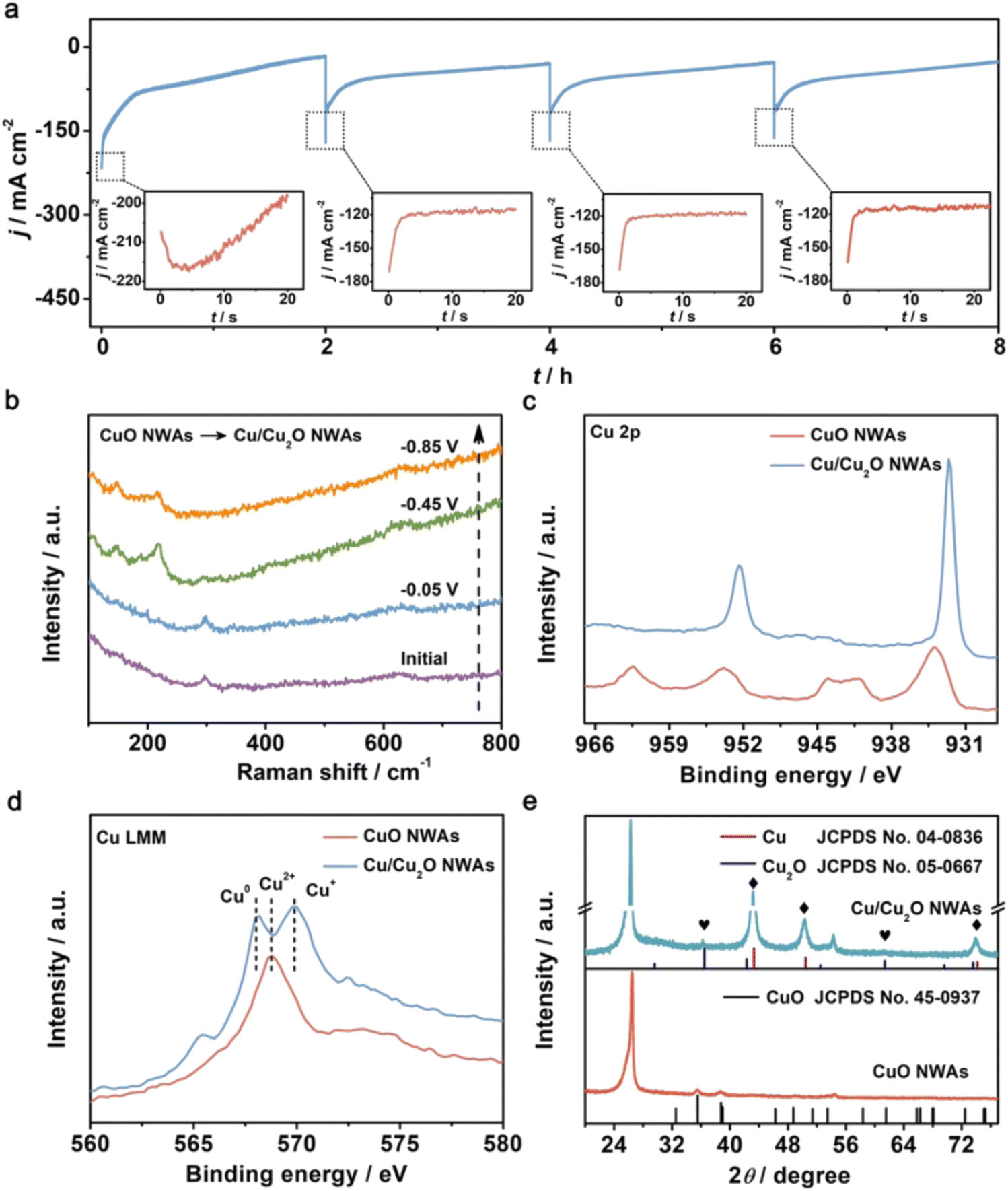 | ||
| Fig. 10 (a) The i–t curves of CuO NWAs during four consecutive cycling NRA processes at −0.85 V. Insets: enlarged details in the dotted box. (b) In situ electrochemical Raman spectra of CuO NWAs under given potentials. (c) Cu 2p XPS spectra of CuO NWAs and Cu/Cu2O NWAs. (d) Cu LMM AES spectra and (e) XRD patterns of CuO NWAs and Cu/Cu2O NWAs. Reprinted with permission from ref. 50. Copyright 2020 Wiley-VCH Verlag GmbH & Co. KGaA, Weinheim. | ||
Qin et al. investigated the mechanism of nitrate reduction to ammonia on different exposed facets of copper oxides. Two exposed facets of Cu2O, namely, Cu2O (111) and Cu2O (100), were investigated. The authors found that Cu2O (100) achieved higher selectivity and activity compared to Cu2O (111) due to the lower barrier energy. The variation in electronic properties was considered to be the reason for the difference and was investigated through theoretical calculations. Ren et al. fabricated a concave–convex surface Cu2+1O layer on Cu nanowires.48 In this electrode material, the interior metallic Cu improved the electronic transmission ability while the exterior Cu2+1O layer provided more active sites for nitrate reduction on the electrode surfaces. Besides, the Cu/Cu2+1O interface affected the modulation of the Cu d-band center, thus tuning the adsorption energies of various intermediates in the process. The highest ammonia-yielding FE of 87.07% was achieved under −1.2 V vs. saturated calomel electrode in a neutral solution.
Surface metal is usually considered as the active site in electrocatalytic reactions. Thus, anionic species including oxygen vacancies, hydroxyl groups, anion doping, etc. have been widely reported in recent works to be beneficial in promoting the activity of catalysts.110–114 For Cu oxide catalysts, creating oxygen vacancies using plasma treatment is an effective method for further improving the electrocatalytic NO3RR to ammonia.91 The laser-irradiation technique is an effective strategy for creating oxygen vacancies.117 Geng et al. employed laser irradiation in fabricating oxygen vacancy-rich CuOx nanoparticles which finally realized a large ammonia yield rate of 449.41 μg h−1 mg−1 with a FE of 74.18% at −0.25 V vs. RHE.118 Besides, Gong et al. reported the promotion of oxygen vacancies and hydroxyl groups on the surface of Cu2O after plasma treatment, facilitating better adsorption of nitrate and proton transfer. This contributed to a strongly enhanced selectivity, leading to outstanding selectivity reaching 85.7% and FE reaching 89.54% towards ammonia. Further in depth, the impact of plasma treatment time was studied, with results indicating that the hydroxylation of material surface reached the peak at a treatment of 40 min while a further increase in treating time led to the loss of hydroxyl groups from the surface.115,116
3.4. Cu-based alloy
Compared with single metal catalysts, alloy metal catalysts could modify the charge distribution on the catalyst through the introduction of other metals.45 On the one hand, heterogeneity within and between particles gives rise to various active sites and particle morphologies.119,120 In the nitrate reduction reaction, additional metals can introduce their intrinsic properties, such as inhibition of nitrite production or formation of sequential reaction mechanisms, thus improving the electrochemical performance of the catalyst.74,79,84,121–123 On the other hand, some researchers believed that Cu-based alloys could enhance the resistance to corrosion significantly and improve the long-term stability compared with Cu monometal catalysts.94,121,122,124,125 Indeed, combining copper (Cu) with a metal of lower electronegativity can mitigate oxidation, reducing Cu2+ formation. This strategy enhances the corrosion resistance of the Cu-based alloy, as the secondary metal's electron-donating capacity decreases the likelihood of Cu oxidation. Additionally, forming heteroatomic Cu–M bonds with high dissociation energy further inhibits Cu dissolution. These strategies collaboratively enhance the corrosion resistance of Cu-based alloys, significantly improving the long-term stability of Cu-based electrocatalysts, making them suitable for harsh environments and extended use.126Guo et al. reported metasequoia-like CuFe nanocrystals as a high-performance electrocatalyst for the NO3RR.94 The doping of Fe deepened the energy level of the Cu 3d band and favourably tuned the adsorption energy of the reaction intermediates, which led to improved activity with high FE and selectivity. Sargent et al. introduced Ni to form a CuNi alloy system in which the d-band center of Cu was tuned, and the adsorption energy of intermediates was modified. The positive shift of the d-band center was proved by combining the results of UPS and XPS. Also, the mechanism was further confirmed through DFT studies. Compared with pure Cu, the modified Cu50Ni50 alloy catalyst achieved a six-fold increase in NO3RR activity in the electrolyte comprising 1 M KOH and 100 mM KNO3. Gao et al. alloyed Cu with Ru and fabricated the reduced-graphene-oxide-supported RuCu alloy catalysts (RuxCux/rGO) for direct NO3RR.84 The efficient activity of RuxCux/rGO can be attributed to the synergistic effect between Ru and Cu sites through relay catalysis, in which Cu exhibits efficient activity in the reduction of NO3− to NO2−, while Ru shows excellent activity in the reduction of NO2− to NH3. In addition, doping Ru with Cu can adjust the d-band centre of the alloy and effectively regulate the adsorption energies of NO3− to NO2−, thus promoting the ammonia production performance.
The CuCo alloy is one of the most widely reported types of electrocatalysts for NO3RR.127–130 For this Cu–Co binary catalyst, He et al. also proposed a tandem catalysis mechanism.131 Specifically, Cu was the perfect active site for binding NO3− and catalyzing NO3− to NO2− while Co was highly selective towards the conversion of NO2− to NH3. Based on prior research, Fang et al. reported a CuCo bimetallic catalyst with excellent activity and selectivity for nitrate reduction to ammonia.92 At −0.2 V vs. RHE, the CuCo nanosheet delivered a FE of 100% under an industrial current density of 1035 mA cm−2 under alkaline condition (1 M KOH with 100 mM KNO3), representing the world-record performance for NO3RR so far. The addition of Co to Cu resulted in a fast electron transfer rate, as shown in electron transfer numbers and Tafel slopes (Fig. 11), providing electrons and hydrogen protons to nearby Cu species efficiently and enhancing the utilization of nitrate. In situ Fourier transformed infrared spectroscopy (FTIR) and in situ SHINERS associated with DFT calculations were applied to clarify the mechanism of the synergy effect of Cu and Co. Similarly, Fu et al. reported self-supported CoO/Cu foam as an efficient NO3RR catalyst.132 Through the establishment of an electric field at the interface between Cu foam and CoO, the electron transfer from Cu to CoO is enhanced, resulting in the positive charge on Cu, which further enhances the adsorption of nitrate ions. This mechanism greatly improved the selectivity for ammonia, reaching a Faraday efficiency of 96.7% with the highest ammonia yield rate of 4.3 mg cm−2 h−1, which is far beyond the performance of blank Cu foam and CoO on Ni foam. Recently, Liu et al. also reported core–shell heterostructure nanowire arrays (CuO NWAs@Co3O4) for NO3RR.130 The copper–cobalt heterostructure is synthesized through a simple two-step method including in situ growth of Cu(OH)2 NWAs and the on-site growth of Co3O4 flocs. This resulted in a high ammonia yield rate of 1.915 mmol cm−2 h−1 along with a Faraday efficiency of 99.17%. The authors attribute the enhanced activity to the synergistic effect of the active phases and improved atomic hydrogen adsorption. Based on the above views, although the specific mechanisms may vary between these works, they all shed light on the potential of utilizing Cu and Co in combination for enhanced catalytic performance.
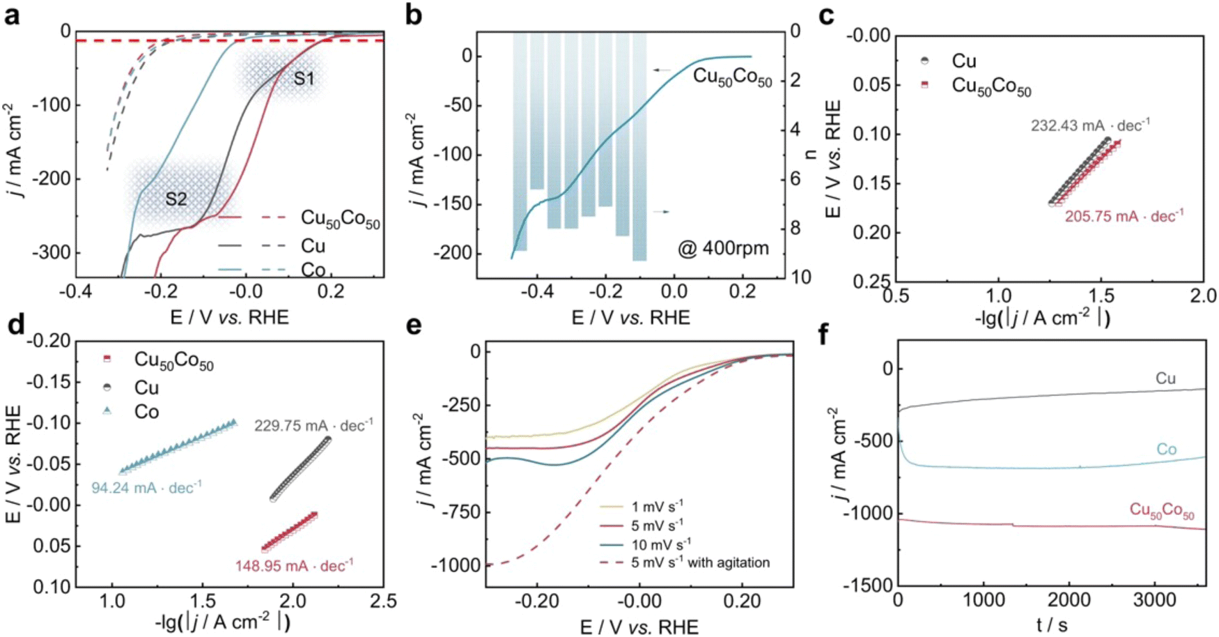 | ||
| Fig. 11 Electrochemical performance of NO3RR over Cu50Co50, pure Cu, and pure Co modified Ni foams reported by Fang et al. (a) j–E curve (80% i–R corrected) of the samples in a 1 M KOH solution containing 100 mM KNO3 (solid lines) or in the absence of KNO3 (dotted line) at a scan rate of 1 mV s−1. (b) j–E curve (80% i–R corrected) at 400 rpm and electron transfer numbers at different potentials. (c) and (d) Tafel slopes in the potential range of peaks S1 and S2, respectively. (e) j–E curves over Cu50Co50 in a 1 M KOH solution containing 100 mM KNO3 at different scan rates with/without agitation. (f) Time-dependent current density curves at −0.2 V with a magnetic stirring speed of 1000 rpm. Reprinted with permission from ref. 92 Copyright 2022 Springer Nature. | ||
Recently, there have been some works comparing different Cu-based alloys transversely from not only theoretical but also experimental perspectives. Zheng et al. studied a series of Cu-based diatomic site catalysts (CuTM/g-CN, TM = Fe, Co, Ni, Zn, Ti, V, Cr, and Mn) using theoretical insights.133 Zhao et al. focused on the horizontal comparison between different Cu-based alloys (abbreviated as CuM), including CuCo, CuFe, and CuNi on the ordered mesoporous carbon (abbreviated as OMC).124 The CuM/OMC series were synthesized through a simple hydrothermal method assisted with the coprecipitation method and different ratios of metal were investigated. Among them, the optimal ammonia yield rate at −0.8 V vs. RHE follows the following order: Cu5Fe5/OMC > Cu5Co5/OMC > Cu7Ni3/OMC > Cu/OMC > Fe/OMC > Co/OMC > Ni/OMC > OMC. All the CuM catalysts showed superior ammonia yield rates compared with monometallic catalysts, experimentally proving the promotion of synergistic effects in NO3RR.
To sum up, the four main types of Cu-based catalysts introduced above all show great potential in realizing high activity and selectivity in NO3RR. Meanwhile, considering the outstanding advantages such as low cost and high electrical conductivity, Cu-based catalysts merit further investigation and hold promise for practical applications in ammonia production via NO3RR. Several strategies are commonly employed for the development of Cu-based catalysts in NO3RR. (1) Nanostructuring: reducing the size of Cu catalysts to the nanoscale can increase the surface area and expose more active sites, leading to improved catalytic activity. Cu nanoparticles, nanowires, or even Cu single atoms have shown promising performance in NO3RR due to their unique electronic and structural properties. (2) Surface modification: introducing oxygen vacancies or nitrogen doping into the Cu-based catalyst surface can improve their electrocatalytic performance in NO3RR. (3) Crystal facet engineering: controlling the crystal facets of Cu catalysts can significantly influence their catalytic activity. Optimizing the exposure of specific facets (e.g., Cu (100) and Cu (111)) can enhance the overall catalytic performance. (4) Alloying with other metals: incorporating Cu with other metals, such as Co, Ag, Ru or Pd, can enhance the catalytic activity and selectivity of Cu-based catalysts through the synergistic effect.
4. Methods of product/mechanism analysis
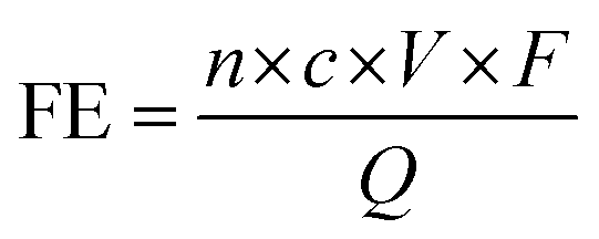
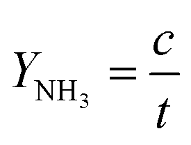
To justify the performance of electrocatalytic synthesis of ammonia, three evaluation criteria should be adopted, which are activity, selectivity, and stability. Regarding the judgment of the electrode activity and stability, the electrochemical tests, such as cyclic voltammetry (CV), linear sweep voltammetry (LSV), chronoamperometry, electrochemical impedance spectroscopy (EIS) analysis, electrochemical surface area (ECSA), etc. are universal methods.123 These tests are usually conducted and recorded through an electrochemical workstation. A three-electrode system is a common setup used in electrochemical experiments, particularly in H-cell configurations. It consists of two chambers separated by a membrane and three electrodes: a working electrode, a reference electrode, and a counter electrode. The three-electrode system in an H-cell configuration allows precise control and measurement of the electrochemical processes, making it a widely used setup in electrochemical research and applications. However, despite being essential indicators, electrochemical test results alone are insufficient to assess ammonia production performance. One major challenge is that the products of this reaction are complex and diverse due to the wide valence distribution from +5 to −3 in NO3RR. Simultaneously, the competing HER, which affects product selectivity, also contributes to a portion of the cathodic current. Besides, the electrochemical test results can only imply the occurrence of corresponding reactions in terms of the onset potential. Therefore, the products of NO3RR and ammonia yield could not be analyzed precisely and quantitively in this way.134 Considering the evaluation of selectivity, product detection methods, especially for ammonia detection, are indispensable. As a critical metric for ammonia production, on one hand, Faraday efficiency (FE) describes the efficiency with which electrons are utilized in the system to facilitate NO3RR. Normally, FE is calculated through the comparison of consumed electrons for ammonia production and the total electrons consumed during NO3RR process, and usually expressed in percentage (%). Therefore, obtaining accurate measurements of ammonia yields is essential for the evaluation of the selectivity of this reaction. On the other hand, the ammonia yield rate commonly refers to the rate of ammonia production during the NO3RR process. Typically, this value expresses the quantity of ammonia generated per unit of time, which provides a measure of the productivity of ammonia through the NO3RR process. Although both these parameters are crucial for assessing the performance of NO3RR, differences exist between them. The ammonia yield rate measures the absolute amount of ammonia produced and is a direct measurement of productivity, whereas Faraday efficiency focuses more on the information about the selectivity in the NO3RR process towards ammonia. Besides, the potential (normally expressed as volts vs. reversible hydrogen electrode) at a certain current density refers to the required electrode potential to reach a specific reaction rate of NO3RR, which plays a crucial role in describing the kinetics of the reaction. This potential also has a significant effect on the overall efficiency of the NO3RR process. Energy efficiency (EE) in NO3RR refers to the ability to use energy entering the system for ammonia production and is usually expressed in percentage (%). It is worth noting that, unlike the above evaluation metrics, EE evaluates the overall energy efficiency of the entire system, whereas, for comparison, FE focuses on the electrochemical processes of the NO3RR.The FE for ammonia production can be calculated based on the equation below:
The yield rate of ammonia can be calculated with the equation below:
The EE for ammonia production can be calculated based on the equation below:
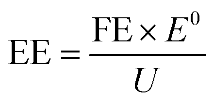
![[thin space (1/6-em)]](https://www.rsc.org/images/entities/char_2009.gif) 485 C mol−1); V is the volume of cathode electrolyte in the H-cell reactor (mL); Q is the total amount of charge consumed (C); E0 is the theoretical electric potential difference of the reactor (V); and U is the practical voltage of the reactor (V).
485 C mol−1); V is the volume of cathode electrolyte in the H-cell reactor (mL); Q is the total amount of charge consumed (C); E0 is the theoretical electric potential difference of the reactor (V); and U is the practical voltage of the reactor (V).
Various techniques such as 1H NMR, UV-vis spectroscopy, and ion chromatography (IC) should be applied in ammonia detection to eliminate interference or contamination from the environment or the catalyst itself.45
In addition to the diversity in products, NO3RR to ammonia is a complicated process involving a wide variety of intermediates. Meanwhile, the composition and structure of some electrocatalysts’ surfaces will also change during the electrochemical reaction process.35 Thus, classical ex situ electrochemical methods are inadequate to clarify the mechanism of various ammonia production pathways as they can only provide indirect information about the reaction. This motivates the development of in situ methods for characterizing electrode active species and reactive intermediates.135 In contrast to the ex situ methods, the most crucial feature of the in situ technique is that it provides direct and accurate information, which contributes to the identification of changes in the process under different conditions.
Therefore, this section will mainly discuss the state-of-the-art methods for ammonia detection and in situ characteristic techniques for electrocatalytic synthesis of ammonia. The structure of this section is shown schematically in Fig. 12.
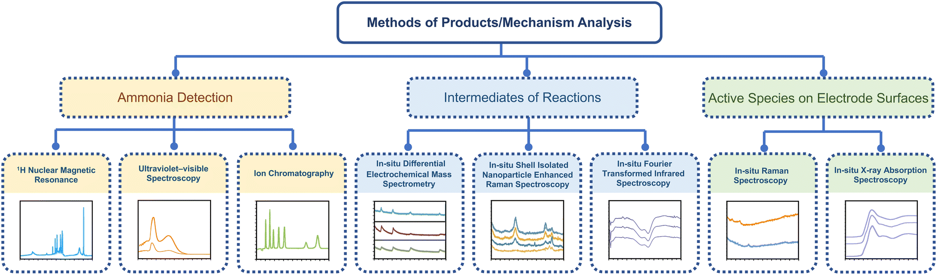 | ||
| Fig. 12 The schematic illustration of state-of-the-art methods for ammonia detection and in situ characteristic techniques. | ||
4.1. Ammonia detection
Based on the Lambert–Beer law, UV-vis spectroscopy is a quantitative technique that can be used to measure the concentration of a chemical substance through light absorption at a typical wavelength in gases and solutions.136 The detected substances can be quantified using a calibration curve based on standard samples. In ammonia detection, UV-vis is the most common method due to its low cost and simple operation.42 Before the absorption test, chromogenic agents are required and the indophenol blue method is one of the widely used colourimetric methods, which requires three reagents: a potassium sodium tartrate–salicylic acid solution, sodium hypochlorite solution, and sodium nitroferricyanide solution.89 The indophenol blue maximum absorbance could be measured at around 653 nm.137 Another commonly used chromogenic agent is Nessler's reagent, and the maximum absorbance is usually measured at around 420 nm. However, the maximum absorbance wavelength is not a fixed figure and is affected by the pH of the solution and the differences in the spectrometer itself.138 Besides, the concentration of the detected substance should be adjusted to the suitable absorption range of each spectrometer. Thus, the errors that may occur during the preparation of the solution are magnified many-fold during the dilution procedure, requiring extra precautions.IC is another common method for ammonia detection, employing the principle of ion exchange. Similarly, the electrolyte should be diluted to the detection range, and pre-treatment is required to avoid the contamination and damage of the equipment by organic substances and heavy metal ions.139 The results of IC should be quantitively close to those of UV-vis, thus confirming the accuracy and reliability of both methods.134
Although the common methods can detect ammonia concentration with relative accuracy, an isotopic labeling experiment using 1H NMR is prominent in determining the N-source of the product. Zhao et al. introduced the atomically dispersed bimetallic Fe–Co electrocatalysts for electrocatalytic nitrogen reduction to ammonia with an extraordinary Faradaic efficiency of 79.0 ± 3.8%.59 The isotopic labelling experiment confirmed the high selectivity of NRR, which was performed using 15N2 and 14N2 saturated in a 0.1 M Na2SO4 electrolyte at −0.30 V (vs. RHE) and undergoing reaction for 2 hours. D2O was used as a solvent for the dissolution of internal standards. For qualification, three characteristic peaks appear when using 14N as the source of nitrogen, and only two peaks appear when using 15N.140 For quantification, the yields of 15NH4+ and 14NH4+ were calibrated with the standard curves.141 The closely approximated values of 15NH4+ and 14NH4+ implied that the ammonium produced in this reaction originated from the Fe–Co electrocatalyzed nitrogen reduction.
Besides, the concentration of reactants and by-products should also be clarified when measuring ammonia production performance. For liquid substances, e.g., nitrate and nitrite, IC is mainly adopted, and the gaseous products can be typically quantified using gas chromatography (GC).142 In all these measurements, repeats of over 3 times should be performed to ensure dependability.
4.2. Intermediates of reactions
Due to the complicated electron pathway involved in electrocatalytic synthesis of ammonia,19,60 divergent intermediates are formed in this process, which increases the difficulties of elucidating the overall reaction mechanism. Appropriate in situ characterization methods are essential for understanding electrocatalytic processes at the molecular level and should be applied depending on different situations.In situ FTIR, pioneered by Bewick et al. in the 1980s is effective in the detection of the adsorbates, molecules, and reaction intermediates.144–148 In ammonia production reactions, usually, in situ FTIR is employed to differentiate the reactive intermediates absorbed on the catalyst electrodes. Liu et al. applied this technique in the mechanism study of nitrate reduction to ammonia.83 In Liu's work, a novel electrocatalyst consisting of Rh single-atoms and clusters dispersed on Cu nanowires was synthesized and demonstrated to exhibit high-activity and high-selectivity for the electrocatalytic synthesis of ammonia. The results of in situ infrared spectroscopy clearly showed that only a weak peak related to –NH2 could be detected for Cu nanowires, while after introducing Rh single-atoms/clusters to the electrocatalyst, an obvious peak of –NH2 could be detected. Through the comparison of the results, the authors suggested that the introduction of Rh improved the H-surface absorption drastically, indicating that the hydrogenation step of this electrocatalyst was no longer the rate-limiting step of the nitrate reduction process (Fig. 13). This hypothesis regarding the mechanism was identical to the results of 1H NMR, in situ DEMS, in situ EPR spectra, etc. The mechanism and pathway of the whole reaction were proposed based on these results with the aid of DFT calculations.
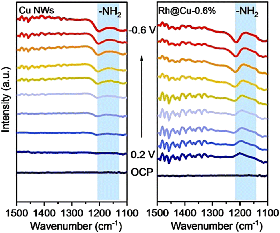 | ||
| Fig. 13 Electrochemical in situ infrared spectroscopy (IR) of Rh@Cu-0.6% and Cu NWs under different potentials in a 0.1 M Na2SO4 electrolyte (pH 11.5) with 0.1 M KNO3 by Liu et al. Reprinted with permission from ref. 83 Copyright 2022 Wiley-VCH GmbH. | ||
Yao et al. conducted further DEMS measurements to confirm the molecular formula of N2Hx.152 In Yao's work, DEMS was employed to explore the mechanism of nitrogen and nitrate reduction on the surface of rhodium. The signal of H2+ (m/z = 2) and N2H2 (m/z = 29 for N2H+ and 30 for N2H2+) was detected from 0.4 V to −0.4 V on an Rh-film electrode in both 0.1 M KOH and 0.1 M KNO3 solutions (Ar-saturated) and in 0.1 M KOH solution (N2-saturated) for nitrate reduction and nitrogen reduction, respectively. The signals for H2+ (m/z = 2) and N2H+ (m/z = 29) could be detected in both reactions, while the signals for N2H2+ (m/z = 30) were only detected in the nitrate reduction reaction (Fig. 14). The results implied that N2Hx served as an intermediate in both nitrate reduction and nitrogen reduction. At the same time, the selectivity of NRR was lower than that of nitrate reduction to ammonia, as indicated by comparison of the signals of N2H+ (m/z = 29).
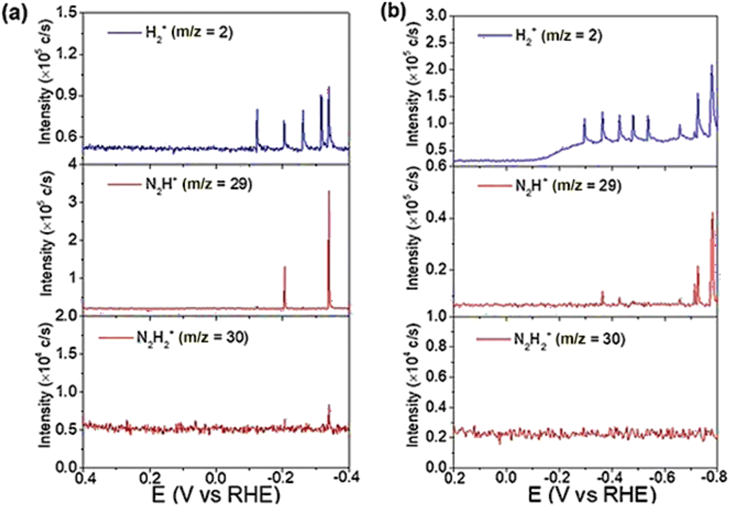 | ||
| Fig. 14 (a) DEMS of H2+ (m/z = 2), N2H+ (m/z = 29), and N2H2+ (m/z = 30) on Rh/C during a scan from 0.4 to −0.4 V in an Ar-saturated 0.1 M KOH + 0.1 M KNO3 solution (2.5 mV s−1). (b) DEMS of H2+ (m/z = 2), N2H+ (m/z = 29), and N2H2+ (m/z = 30) on Rh/C during a scan from 0.4 to −0.4 V in a N2-saturated 1 M KOH solution (5 mV s−1). Reprinted with permission from ref. 152 Copyright 2020 Wiley-VCH Verlag GmbH & Co. KGaA, Weinheim. | ||
As a state-of-the-art branch in Raman spectroscopy techniques, in situ SHINERS measurement is often applied in identifying the reactive intermediates on the catalyst surfaces in the area of electrochemical catalysis due to its accuracy and stability.35 Until now, many researchers have applied SHINERS to study the mechanisms, including the hydrogen evolution reaction, oxygen reduction reaction, CO reduction/oxidation reaction, nitrate reduction reaction, etc.156 For the nitrate reduction reaction, Jr et al. used SHINERS to reveal a series of reactive intermediates involved in the process of nitrate reduction, such as NO2− and HNO.113 Specifically, in Jr's work, the intermediates of nitrate reduction were observed by SHINERS on three crystal planes of copper, which were Cu (100), Cu (111) and Cu (110), respectively. The intermediates observed on the three planes were similar, thus indicating the same mechanism and reaction pathway. Each peak of SHINERS was analyzed in detail and assigned to a reactive intermediate. As shown by the results, the mild intensity peaks at 509 cm−1 and 619 cm−1 could be assigned to the formation of Cu2O due to partial oxidation. Two characteristic peaks could be observed in Cu (110) and Cu (111) but not in Cu (100), indicating the low formation rate of Cu2O on Cu (100), which was a key active species on the electrode surface. The LSV curves were in accordance with this explanation for the relatively inactive nitrate reduction performance of Cu (100).157
Furthermore, this method investigated the mechanism behind the decrease in nitrate reduction performance caused by chloride ions. Cl− is known to form a chloride array on the surface of Cu at around −0.3 V vs. RHE, which has been demonstrated to impede the copper-based nitrate reduction.65 SHINERS verified this phenomenon and gave a detailed reaction pathway in this work (Fig. 15). According to the results of SHINERS, there was no evidence of adsorption of nitrite or nitroxyl species when the potential was scanned from 0 mV to 800 mV compared to the Cl− free system. Instead, weak peaks associated with NH4+ and NH3 appeared at around −0.5 V vs. RHE on Cu (100), thus implying a different pathway for nitrate reduction on chloride-decorated copper electrodes. Also, as a high-sensitive surface detection technique, SHINERS could be used in the detection of active species on the electrode surfaces, which is discussed in the next section.
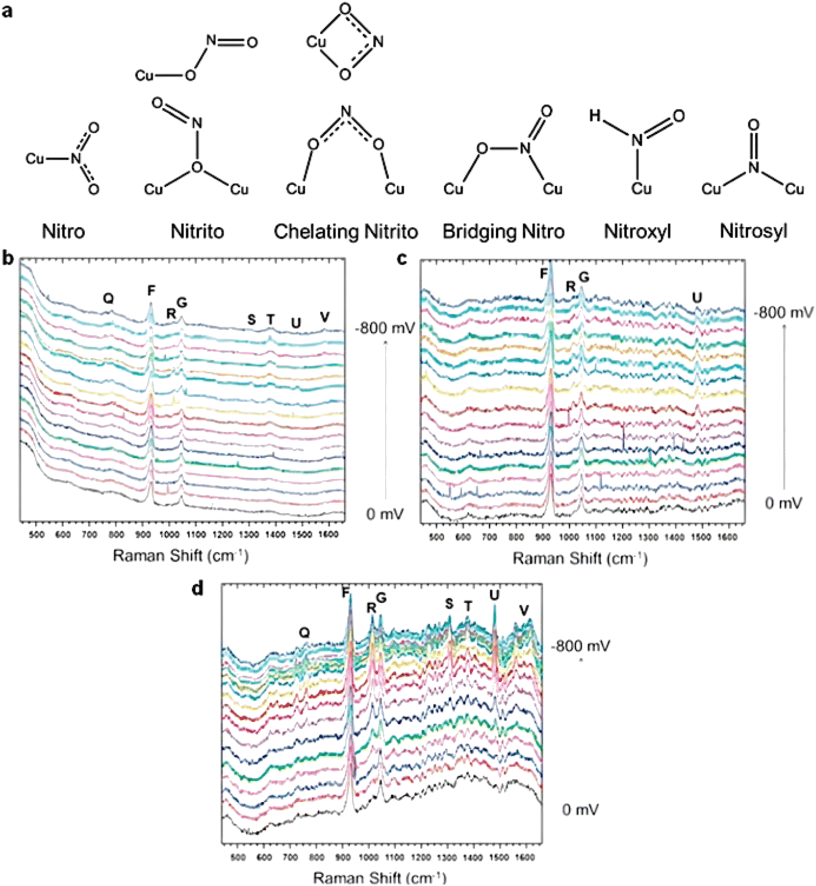 | ||
| Fig. 15 (a) Adsorption modes of nitrite, nitric oxide, and HNO on the Cu surface. Electrochemical in situ SHINERS spectra collected from (b) Cu (100), (c) Cu (111), and (d) Cu (110) in a 0.1 M HClO4 solution with 0.05 M HNO3 and 10 mM HCl at a potential between 0 and −0.8 V vs. Ag/AgCl. Reprinted with permission from ref. 157 Copyright 2016 Elsevier Ltd. | ||
In addition to the three in situ characterization methods mentioned above, there are some other techniques applied in the in situ analysis of reactive intermediates. In situ IC is a technique based on traditional IC and is conducted to detect the ions generated or consumed over time. Moreover, a fully automated and low-cost IC system for in situ analysis of nitrite and nitrate in natural waters was reported in 2020 by Paull et al.158In situ electron spin resonance (ESR) is a microwave absorption spectroscopy technique used to detect and study paramagnetic substances containing unpaired electrons. Hydrogen radicals play an important role in the reduction of nitrate to ammonia and can be monitored with in situ ESR to help elucidate the mechanism of the reaction.75
In brief, with the development of in situ techniques, more and more new methods are widely used to explain complex catalytic mechanisms.
4.3. Active species on electrode surfaces
Since electrochemical processes are investigated at the interface between a liquid electrolyte and a solid electrode,159 identifying and thoroughly exploring the active species on the electrode surface are important. The common ex situ characterization studies for electrode materials can only give the static result rather than continuous analysis during dynamic reaction processes. In this regard, electrochemical in situ characterization studies for active species are crucial for studying and designing the electrocatalyst.Normally, electrochemical in situ Raman spectroscopy measurements are carried out with a Raman apparatus and in situ Raman cells connected to an electrochemical workstation.35 As a critical component, the in situ Raman cell was once a major limitation in performing this measurement.162 Nowadays, an in situ Raman cell usually contains a working electrode, a counter electrode, a reference electrode, and a quartz optical window. To avoid corrosion of the solution and erosion of the instrument by gases, the Raman cell must be equipped with a sealing system for the optical window. Intervention from the solution signal under experimental conditions should be avoided as much as possible by using a thin layer of solution (0.1–1 mm between the electrode and the window), which is important for microscopic Raman systems. Thick optical windows or solution layers might cause changes in the optical path of the microscope system and degrade the collection efficiency of the surface Raman signal.
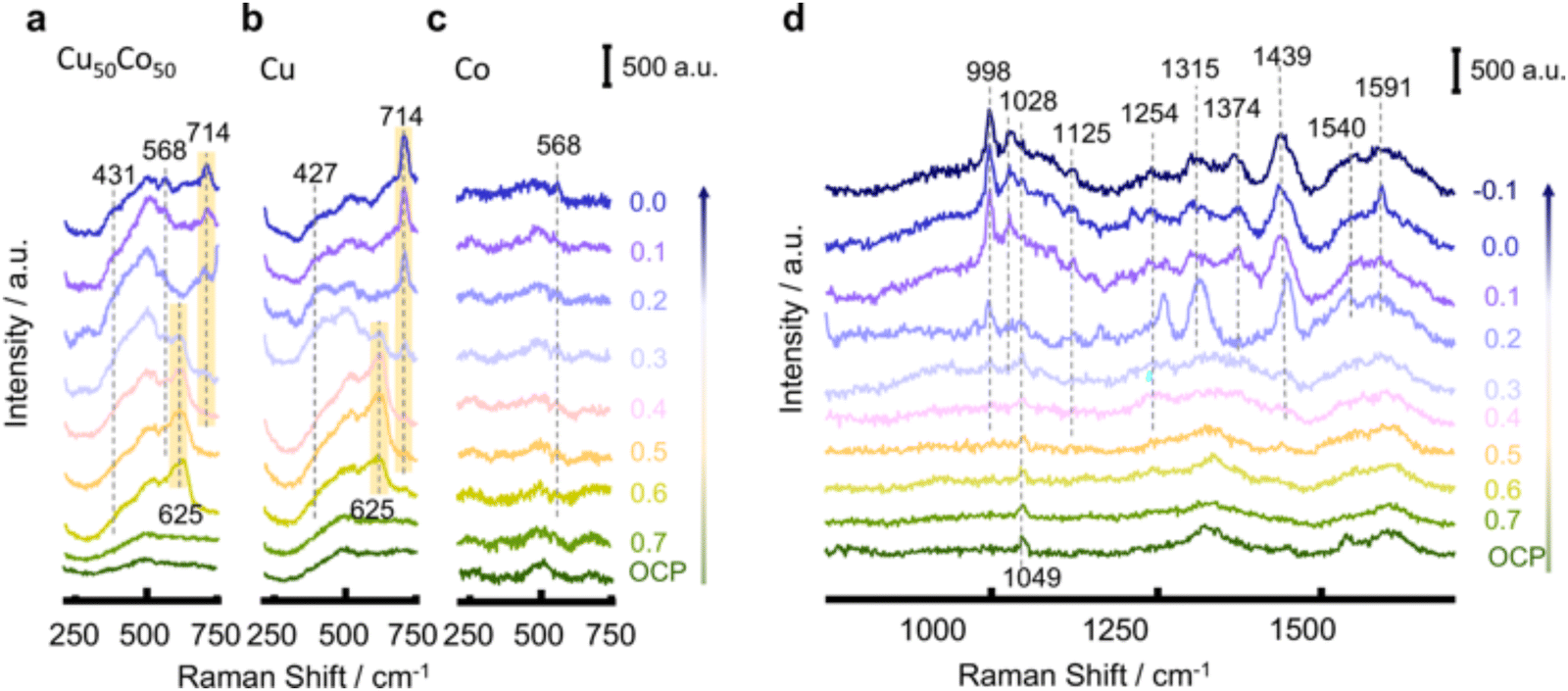
Fang et al. applied SHINERS spectra in probing both the surface of the catalyst and the reduced intermediates absorbed during the NO3RR process.92 The spectra between 230–750 cm−1 on Cu50Co50, Cu, and Co mainly clarified the chemical properties of the catalyst on the surface. As shown in Fig. 16, the characterization peaks belonging to Cu2O (625 cm−1) can be observed when the potential is over 0.6 V in Cu50Co50 and Cu. However, when the potential decreased, the peaks for the oxides gradually shrank. The reduction to the metallic state (Cu) even before the NO3RR indicated that the surface of the catalyst was partially oxidized by the air and the real active sites for NO3RR were metal Cu and Co. Besides, the peaks at 431 cm−1 and 568 cm−1 could be assigned to Cu–Ox and Co–Ox caused by the adsorption of oxynitride on the catalyst surface, respectively.163,164 The spectra between 750–1700 cm−1 clarified the signals of nitrate and intermediates adsorbed on the surface. With the potential shift from open circuit potential (OCP) to −0.1 V, the peaks for nitrate and intermediates appeared sequentially. In this way, the deoxygenation pathway was proposed to occur in the sequence of NO3− → *NO3 → *NO2 → *NO, while the hydrogenation pathway was suggested to occur in the sequence of *NO → *NOH → *NH2OH → *NH3 → NH3. Moreover, by comparing the peaks on Cu50Co50 and Cu, the peak related to NO2− appeared only on the Cu surface, suggesting its poor ability for further deoxygenation of nitrite.
 | ||
| Fig. 16 SHINERS spectra between 230–750 cm−1 on (a) Cu50Co50, (b) Cu, and (c) Co. (d) SHINERS spectra between 750–1700 cm−1 on Cu50Co50 in 100 mM KNO3 + 10 mM KOH during cathodic polarization from 0.7 to −0.1 V, by Fang et al. Reprinted with permission from ref. 92 Copyright 2022 Springer Nature. | ||
Wang et al. investigated the reactive species involved in nitrate reduction for ammonia production through the in situ Raman test.89 The initial Raman spectrum of the island-like copper structure indicated the existence of Cu2O and a small amount of CuO. With the reduction reaction happening on the electrode surface, the peak of CuO disappeared immediately after applying a negative potential, while the intensity of the peaks for Cu2O first increased to the maximum value and then decreased gradually with the negative shift in potential. Thus, it can be concluded that CuO was first reduced to Cu2O and then reduced further to Cu along with the reaction of nitrate reduction to ammonia. The conclusion above suggested that the real active sites for nitrate reduction were Cu2O formed during the reduction process rather than CuO on the initial electrode.
In addition, Zhang et al. reported an efficient electrocatalyst for green ammonia production starting from CuO nanowire arrays, which were then in situ converted into Cu/Cu2O nanowire arrays during the reduction process of nitrate to ammonia.50 The speculation regarding active sites was also confirmed by in situ Raman spectroscopy measurement, which was in accordance with Li's work.
Chen et al. adopted XAS measurement to provide a deeper understanding of the electronic properties of the Cu-based electrocatalyst (Ru-CuNW).77 The Ru-dispersed Cu nanowire catalyst with outstanding performance was reported to reach an industrial-grade current of 1 A cm−2 for nitrate reduction to ammonia while retaining high selectivity (FE of 93%). To clarify the structure and composition of the high-performance catalyst, the material was monitored by both ex situ XAS and in situ XAS. The ex situ Cu K edge XANES suggested that CuO/Cu2O was reduced to the Cu metallic state after pre-reduction. The in situ Cu K edge XANES clearly shows the process of gradual reduction from oxide to metal. Moreover, the metallic state of Cu was maintained throughout the procedure of nitrate reduction. The ex situ Ru K edge XANES also suggested that RuOx was successfully reduced to metallic ruthenium after pre-reduction, and in situ XAS could identify this procedure. The metallic Ru was proved to be the active site for ammonia production as well. Besides, the Fourier-transformed extended X-ray absorption fine structure (FT-EXAFS) clarified the coordination structure of Ru–Cu NW and Ru–CuO NW. As shown in FT-EXAFS, there was no peak for Ru–Ru (2.39 Å) and only the peak for Ru–O (1.50 Å) could be found in Ru–CuO NW, indicating the even dispersion of Ru atoms on the surface of Cu nanowires. Due to the extremely close positions of peaks for Ru–Cu (2.37 Å) and Ru–Ru (2.39 Å), it was hard to differentiate one from another. However, this peak was attributed to Cu–Ru based on other characterization studies mentioned later in the paper.
Similarly, Zhong et al. applied in situ XAS to unravel the origin of the high activity of FePc-pz in the NRR.166 The chemical state of Fe and its coordination structure were identified in a profound way. As shown in the in situ Fe K edge XANES profile (Fig. 17), there was no apparent change in the catalyst composition during the NRR. At different potentials, the pre-edge resonance signals of FePc-pz samples were different from those of Fe foils but similar to the signals of Fe(II)Pc, indicating the chemical state of Fe during the nitrogen reduction process. Meanwhile, the coordination of FeN4 sites in the NRR was unveiled through in situ Fe K-edge EXAFS analysis. With the potential moving negatively, the peak assigned to Fe–N of FePc-pz was shifted from 1.5 Å to 1.2 Å, suggesting that the Fe–N bond was compressed during NRR since the absorbed N intermediates and hydrogen radicals interacted with the Fe active sites. However, when the potential shifted back to the open circuit voltage, the Fe–N bond remained at 1.5 Å. It could be concluded that there was no structural damage in FePc-pz, thus confirming the stability of FeN4 active sites in the NRR process.
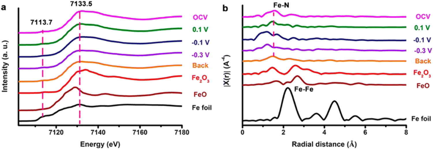 | ||
| Fig. 17 (a) Fe K-edge XANES and (b) EXAFS profiles of Fe foil, FeO, Fe2O3, and FePc-pz on carbon paper under different applied potentials (from OCP, +0.1, −0.1, and −0.3 V vs. RHE, then back to OCP) by Zhong et al. Reprinted with permission from ref. 166 Copyright 2021 American Chemical Society. | ||
Apart from the characterization methods discussed in this section, there are many other in situ techniques also that could be employed to investigate the interface of electrochemical reactions, thus providing profound insights into the material surface structures and complicated mechanisms for electrocatalytic synthesis of ammonia. In conclusion, with the development of modern characterization techniques, more and more state-of-the-art in situ methods are introduced, systematically contributing to the advancement of in-depth mechanistic studies.
5. Practical application and economic analysis
As a win–win strategy, the nitrate reduction to ammonia provides the possibility for both nitrate removal from wastewater and ammonia recovery.167 The illustration of the practical application of nitrate-to-ammonia conversion from wastewater is shown in Fig. 18. To date, most research works have focused on the material and mechanism perspectives as summarized in previous sections. There are two main lines of efforts to address the needs of practical applications: real wastewater (nitrate-rich) treatment and scaling-up prototypes.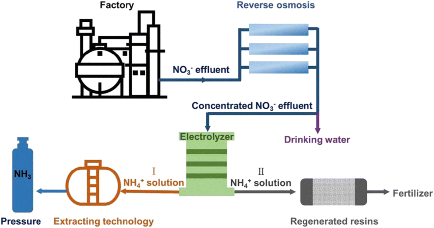 | ||
| Fig. 18 The schematic illustration of the practical application of nitrate-to-ammonia conversion from wastewater. Reprinted with permission from ref. 50 Copyright 2020 Wiley-VCH. | ||
5.1. Real wastewater treatment application
For municipal wastewater, the concentration of nitrate is usually in the range of 10–200 mg L−1 N–NO3.168 These two values are much lower than the most prevailing concentration of 0.1 M (1400 mg L−1 N-NO3) adopted in NO3RR, which makes its application in wastewater treatment challenging. It is heartening to find some recent representative works with their efforts focusing on the real wastewater-to-ammonia conversion utilizing Cu-based catalysts.169–171 For example, Ma et al. applied the outflowing wastewater from the Stockholm water plant as an electrolyte in NO3RR with an extremely low nitrate of 3.5 mg L−1 N-NO3.171 Cu nanorods are utilized as the catalyst for the selective nitrate conversion to ammonia. After the continuous conversion for 3 h at −0.6 V vs. RHE, 98% of the nitrate could be converted into ammonia. Zhao et al. also reported a 3D Pd–Cu(OH)2/CF cathode for the complete removal of nitrate with an initial concentration of 50 mg L−1 N-NO3.169 In 2023, Wang et al. employed a free-standing membrane172 incorporating Cu single atoms for NO3RR in flow-through electrofiltration.Besides, as a significant characteristic of wastewater, inorganic ions are complicated and unavoidable. These ions include both cations and anions such as Na+, K+, Ca2+, Mg2+, Al3+, SO42−, Cl−, I−, etc. Some monovalent cations can promote the performance of NO3RR by forming instantaneous neutral ion pairs, changing the bilayer structure of the cathode.167 The ion pair would attract the reducing ion (nitrate), which strengthens the connection between the cathode and reducing ions and facilitates easier reduction of nitrate. Besides, the HER would be suppressed with a suitable type and number of cations due to the repulse of H+. Meanwhile, cations like Mg2+ and Ca2+ have a negative effect on the NO3RR. Due to the continuous consumption of H+, precipitates would form on the cathode electrode, thus blocking the active sites of the reaction, which is also known as poisoning.173 Similarly, it has been reported that SO42− would compete with NO3− within a certain potential range for active sites. However, the differences in the enthalpy of adsorption for ions on particular cathodes affect the NO3RR performance and specific situations need to be analysed on a case-by-case basis.29,174
In the context of wastewater treatment application, there exists a substantial scope for advancement and scholarly investigation. This includes the exploration of the effects of low nitrate concentrations. Concurrently, the introduction of inorganic ions into the process presents another significant area for academic inquiry, underscoring the importance of these issues in the field.
5.2. Scaling-up application
Usually at the laboratory scale, single-chamber reactors and dual-chamber reactors (H-cell) are applied for nitrate-to-ammonia conversion with chamber volumes ranging from 30–200 mL (Fig. 19). For industrial-scale ammonia production, the reactor configuration needs to be significantly larger, potentially hundreds of litres or even cubic meters in size. Additionally, the electrolyte should be in a flow mode to ensure a continuous and sufficient supply of nitrate for the conversion process.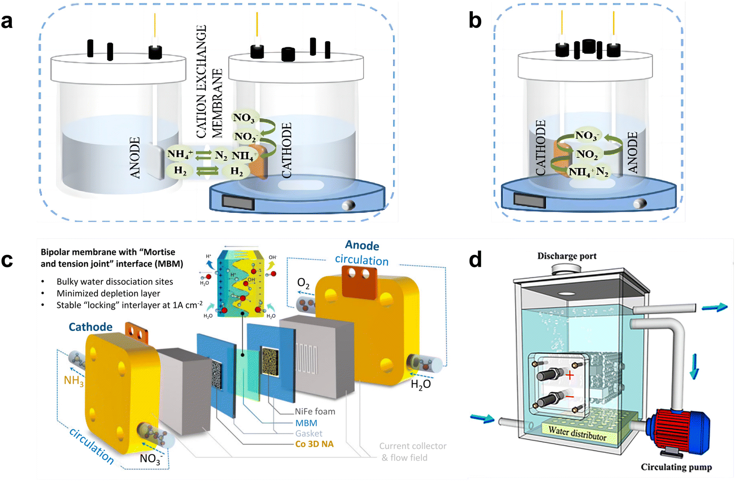 | ||
| Fig. 19 The schematic illustration of a (a) single-chamber reactor and (b) dual-chamber reactor. Reprinted with permission from ref. 167 Copyright 2023 Elsevier B.V. (c) Bipolar membrane reactor for ammonia electrosynthesis in a flow mode. Reprinted with permission from ref. 176 Copyright 2023 Springer Nature. (d) Prototype stack reactor for nitrate-to-ammonia conversion. Reprinted with permission from ref. 175 Copyright 2021 American Chemical Society. | ||
Some recent works have taken this consideration further towards industrial applications. Xu et al. designed a bipolar membrane reactor for continuous electrosynthesis of ammonia from 2000 ppm nitrate (equivalent to 0.034 M).175 In order to achieve ionic equilibrium, a bipolar membrane nitrate reduction process was proposed and the hydrolysis dissociation sites were increased by constructing a three-dimensional physically interlocking interface for the bipolar membrane in this work. The system finally realized a stable ammonia production of over 100 h at 1000 mA cm−2 with a Faradaic efficiency of 86.2% and a maximum yield rate of 68.4 mg h−1 cm−2. The schematic for a bipolar membrane reactor with a serpentine flow field supplying fresh electrolyte is shown in Fig. 19(c). Earlier, in 2021, Zheng et al. made the first trial and constructed a prototype reactor of 500 L for converting nitrate from real chemical wastewater to ammonia, realizing a FE of 90.4% at 2000 mg L−1 N-NO3.176 In this prototype reactor, two electrode stacks with 13 electrode sheets form the electrode module, fully immersed in the electrolyte tank. This electrode module originated in the field of bioelectrochemistry and has the advantage of not only alleviating the problem of limited capacity and reaction sites but also avoiding concentration fluctuations due to high space utilization.176,177
To sum up, the scaling-up production of ammonia from nitrate reduction has not been much studied to date, and further research on the design of the electric stack in particular is highly warranted. Exploring advanced electrode materials, scalable reactors and cost-effective control systems can contribute to enhancing the performance and efficiency of the stack, ultimately advancing the scaled-up production of ammonia.178
5.3. Economic analysis
As mentioned above, the economic effect is a critical part of industrial application of nitrate-to-ammonia conversion.The economic benefits of this strategy are listed below. First, compared with the traditional Haber–Bosch method, which is also the current mainstream for ammonia production, the nitrate-to-ammonia conversion is more sustainable and applicable for inexpensive renewable electricity. Second, it enables the concept of turning waste into treasure. Nitrate pollution is common in various types of wastewater with a normal range of 10–200 mg L−1 N-NO3,168 while this value could even exceed 1000 mg L−1 N-NO3 in some industries like fertilizer, metal, explosives, etc. Third, compared to NRR, the performance of NO3RR in the lab is much closer to the practical requirements, with the pilot breaking through the laboratory barriers.
Specifically, the economic cost of nitrate-to-ammonia conversion mainly includes the initial cost of system construction and installation, operation and maintenance, monitoring and compliance. Among them, energy consumption and the cost of electrode materials are regarded as two crucial factors for the application process.
At this early stage of practical application, several research works pay attention to economic analysis. McEnaney et al. performed a preliminary techno-economic analysis considering only the electricity cost for ammonium nitrate production.179 In this work, preliminary techno-economic considerations suggest that the pathway for recycling spent nitrate into ammonium products is promising and that full conversion to ammonia may be feasible if electricity consumption is sufficiently low. However, the capital costs, price of electricity, and cell efficiency are estimated with given prices and the authors also mentioned that these practical values should be considered for further exploration. Gao et al. studied the economic cost of energy consumption based on an energy-related parameter, which is determined by power and ammonia yield.180 In this work, a profitable region is given where higher nitrate concentration and lower electricity cost are beneficial. It is worth mentioning that this nitrate-to-ammonia process also eliminates nitrate pollution, whereas the normal nitrification/denitrification process is assumed to have an estimated cost of $15.56 per kg-N removed.181 From the perspective of nitrate removal, Wang et al. predicted the energy consumption of this strategy using the Cu/Ti electrode and Cu/GO/Ti electrode, which are 0.82 kW h g−1 nitrate-N and 0.47 kW h g−1 nitrate-N, respectively. According to the average industrial electricity cost at present ($0.005 per kW h), the cost of electricity consumption using Cu/GO/Ti electrodes is estimated to be $2.35 per kg-N removed.180
Although electrodes are a key component of the reactor, their economic analysis is not sufficiently conducted. Cu-based catalysts have been widely recognized for their high activity and selectivity in nitrate-to-ammonia conversion. Meanwhile, the price for the brass mesh (65% of Cu) is $5.7–22.9 per m2, which is undoubtedly suitable for industrial applications. Besides, another factor closely related to the cost of the electrode is the durability of the material itself, which should be taken into consideration on a case-by-case basis in the economic analysis.
In conclusion, the current reports reveal to some extent the great promise of this nitrate-to-ammonia strategy, but it is difficult to arrive at an accurate assessment because of the gaps in the relevant economic analysis. For the future, it is recommended to conduct a detailed feasibility study considering all the factors mentioned above to achieve an accurate economic analysis.
6. Conclusion and outlook
Electrocatalytic ammonia production from nitrate (NO3RR) is promising and highly attractive due to its ambient reaction condition, low energy consumption, and zero CO2 emission. This review summarized the recent progress in elucidating the mechanism of NO3RR, state-of-the-art Cu-based catalysts for NO3RR, corresponding analysis methods for product detection, practical applications and economic analysis conducted to date.In recent years, significant attempts have been made by researchers to design and develop efficient and low-cost catalysts for this reaction. Cu-based catalysts certainly show outstanding kinetics along with selectivity towards ammonia synthesis. Most current research works mainly focus on higher FE and smaller overpotentials, aiming to improve ammonia yield and ammonia selectivity. Among them, nanomaterials with finite structures expose more active sites through a larger specific surface area, which greatly enhances the activity of the material. Also, great achievements have been made in revealing the in-depth mechanisms of NO3RR recently. On one hand, theoretical calculations give insights into the reaction pathways and rationalize a series of experimental observations. Moreover, the activity and selectivity trends of different catalysts can be simulated and summarized, providing guidance for screening and designing efficient catalysts. On the other hand, the widespread utilization of in situ characterization methods enables direct experimental observation during real-time reactions, providing a powerful means for unveiling the reaction intermediates and active species of the electrode surface.
Although the great potential for electrochemical ammonia production via nitrate reduction has been proven, it is still far from the real-environment application and has some challenges that need to be explored and solved. First, as a significant concern in the industry, the long-term stability of Cu-based catalysts during NO3RR should be considerably improved. Although many reported Cu-based catalysts could reach a high FE of over 90%, the problems of corrosion and dissolution still exist especially in acidic environments, leading to inferior stability. Thus, future research and development efforts should focus on optimizing the stability of copper-based catalysts. This could be achieved through various strategies, such as the use of support materials to prevent the sintering of copper particles, the incorporation of stabilizing agents to inhibit the leaching of copper ions, and the modification of the catalyst preparation method to control the oxidation state of copper. For example, it has been reported that the single-atom Cu catalysts are more likely to present appreciable stability due to the strong interactions between Cu atoms and corresponding coordination atoms.104
Second, the conventional electrode fabrication method using polymeric binders (mostly Nafion) to fix the catalyst on the electrode surface would result in inefficient catalyst utilization, reduced conductivity and weakened mass transfer. Even more, the use of expensive Nafion solution adds to the costs in the electrode preparation process, increasing the overall economic cost. Therefore, self-supported catalysts which could be directly utilized as catalytic electrodes are a promising solution to this problem.
Third, large-scale reactors should be developed to fit the practical ammonia production requirements. The magnification of the reactor enables the maximum reaction rate and significantly increases the practical ammonia yield. However, with the scaling up of the reactor, it becomes important to comprehensively consider achieving ideal FE, energy efficiency, and economic efficiency, which was usually neglected in lab-scale reactors. Therefore, the rational design of the reactor and optimized reaction conditions such as cell voltage, temperature, and electrolyte type/concentration should be figured out. Furthermore, an in-depth investigation of mass/charge transport mechanisms at the cell level should be thoroughly conducted.
Fourth, future research efforts should aim at developing electrocatalysts capable of efficiently converting nitrate over a wide range of concentrations, from the low concentrations typically found in groundwater (e.g., 20 ppm) to the high concentrations found in industrial wastewater (e.g., 1000 ppm). The development of electrocatalytic systems that effectively address this wide range of nitrate levels is critical for practical applications in environmental remediation and industrial processes.
Last but not least, insights into the economic estimations in a professional and detailed way should be employed, including the cost of energy consumption, catalyst consumption, reactor construction, etc.
In conclusion, developing electrocatalytic ammonia production reactions from a lab scale to a practical scale will become the trend of research in this field. The development of electrocatalytic ammonia production via nitrate reduction will revolutionize the future sustainable ammonia economy, with Cu-based catalysts as the foundation.
Author contributions
L. A. proposed the topic of the review. X. Z. proposed the outline of the review. K. Z. drafted the manuscript. All authors contributed to the editing of the manuscript.Conflicts of interest
The authors declare no conflict of interest.Acknowledgements
We acknowledge the support from the National Natural Science Foundation of China (no. 22205187), Hong Kong Polytechnic University (CD4D and WZ4Q), and a grant received from the Research Institute for Smart Energy (CDA4) at The Hong Kong Polytechnic University.References
- J. G. Chen, R. M. Crooks, L. C. Seefeldt, K. L. Bren, R. M. Bullock, M. Y. Darensbourg, P. L. Holland, B. Hoffman, M. J. Janik and A. K. Jones, Science, 2018, 360, eaar6611 CrossRef PubMed
.
- D. Saygin, H. Blanco, F. Boshell, J. Cordonnier, K. Rouwenhorst, P. Lathwal and D. Gielen, Sustainability, 2023, 15, 1623 CrossRef CAS
- S. Chatterjee, R. K. Parsapur and K.-W. Huang, ACS Energy Lett., 2021, 6, 4390–4394 CrossRef CAS
-
V. Smil, Enriching the Earth: Fritz Haber, Carl Bosch, and the Transformation of World Food Production, MIT Press, 2004 Search PubMed
- M. Capdevila-Cortada, Nat. Catal., 2019, 2, 1055 CrossRef
- E. Meloni, G. Iervolino, C. Ruocco, S. Renda, G. Festa, M. Martino and V. Palma, Energies, 2022, 15, 3588 CrossRef CAS
- B. H. Suryanto, H.-L. Du, D. Wang, J. Chen, A. N. Simonov and D. R. MacFarlane, Nat. Catal., 2019, 2, 290–296 CrossRef CAS
- Y. Chen, H. Liu, N. Ha, S. Licht, S. Gu and W. Li, Nat. Catal., 2020, 3, 1055–1061 CrossRef CAS
- D. R. MacFarlane, P. V. Cherepanov, J. Choi, B. H. Suryanto, R. Y. Hodgetts, J. M. Bakker, F. M. F. Vallana and A. N. Simonov, Joule, 2020, 4, 1186–1205 CrossRef CAS
- M. C. Etter, Acc. Chem. Res., 1990, 23, 120–126 CrossRef CAS
- H. Liu, H. Wang and J. Xu, CIESC J., 2022, 73, 32–45 CAS
- B. Han, J. Liu, C. Lee, C. Lv and Q. Yan, Small Methods, 2023, 2300277 CrossRef CAS PubMed
- C. Lv, C. Yan, G. Chen, Y. Ding, J. Sun, Y. Zhou and G. Yu, Angew. Chem., 2018, 130, 6181–6184 CrossRef
- S. Chen, S. Perathoner, C. Ampelli, C. Mebrahtu, D. Su and G. Centi, Angew. Chem., Int. Ed., 2017, 56, 2699–2703 CrossRef CAS PubMed
-
M. Khalid, M. R. Hatshan, A. M. B. Honorato, B. Kumar and H. Varela, Nanomaterials for Electrocatalysis, Elsevier, 2022, pp. 317–334 Search PubMed
- S. Z. Andersen, V. Čolić, S. Yang, J. A. Schwalbe, A. C. Nielander, J. M. McEnaney, K. Enemark-Rasmussen, J. G. Baker, A. R. Singh and B. A. Rohr, Nature, 2019, 570, 504–508 CrossRef CAS PubMed
- C. Tang and S.-Z. Qiao, Chem. Soc. Rev., 2019, 48, 3166–3180 RSC
- Z. Geng, Z. Chen, Z. Li, X. Qi, X. Yang, W. Fan, Y. Guo, L. Zhang and M. Huo, Dalton Trans., 2018, 47, 11104–11112 RSC
- H. Shen, C. Choi, J. Masa, X. Li, J. Qiu, Y. Jung and Z. Sun, Chem, 2021, 7, 1708–1754 CAS
- P. Wei, J. Liang, Q. Liu, L. Xie, X. Tong, Y. Ren, T. Li, Y. Luo, N. Li and B. Tang, J. Colloid Interface Sci., 2022, 615, 636–642 CrossRef CAS PubMed
- M. J. Moorcroft, J. Davis and R. G. Compton, Talanta, 2001, 54, 785–803 CrossRef CAS PubMed
- B. T. Nolan, K. J. Hitt and B. C. Ruddy, Environ. Sci. Technol., 2002, 36, 2138–2145 CrossRef CAS PubMed
- P. H. van Langevelde, I. Katsounaros and M. T. Koper, Joule, 2021, 5, 290–294 CrossRef
- S. Garcia-Segura, M. Lanzarini-Lopes, K. Hristovski and P. Westerhoff, Appl. Catal., B, 2018, 236, 546–568 CrossRef CAS
- Y. Wang, Y. Yu, R. Jia, C. Zhang and B. Zhang, Natl. Sci. Rev., 2019, 6, 730–738 CrossRef CAS PubMed
- M. Karamad, T. J. Goncalves, S. J. Villegas, I. Gates and S. Siahrostami, Faraday Discuss., 2023, 243, 502–519 RSC
- H. Shin, S. Jung, S. Bae, W. Lee and H. Kim, Environ. Sci. Technol., 2014, 48, 12768–12774 CrossRef CAS PubMed
- L. Mattarozzi, S. Cattarin, N. Comisso, R. Gerbasi, P. Guerriero, M. Musiani and E. Verlato, Electrochim. Acta, 2017, 230, 365–372 CrossRef CAS
- G. Dima, A. De Vooys and M. Koper, J. Electroanal. Chem., 2003, 554, 15–23 CrossRef
- D. Reyter, D. Bélanger and L. Roué, J. Hazard. Mater., 2011, 192, 507–513 CrossRef CAS PubMed
- J. F. Su, I. Ruzybayev, I. Shah and C. Huang, Appl. Catal., B, 2016, 180, 199–209 CrossRef CAS
- O. Peng, Q. Hu, X. Zhou, R. Zhang, Y. Du, M. Li, L. Ma, S. Xi, W. Fu and Z.-X. Xu, ACS Catal., 2022, 12, 15045–15055 CrossRef CAS
- T. Hu, C. Wang, M. Wang, C. M. Li and C. Guo, ACS Catal., 2021, 11, 14417–14427 CrossRef CAS
- H. Wan, A. Bagger and J. Rossmeisl, Angew. Chem., 2021, 133, 22137–22143 CrossRef
- Y. Wang, C. Wang, M. Li, Y. Yu and B. Zhang, Chem. Soc. Rev., 2021, 50, 6720–6733 RSC
- M. De Groot and M. Koper, J. Electroanal. Chem., 2004, 562, 81–94 CrossRef CAS
- R. Lange, E. Maisonhaute, R. Robin and V. Vivier, Electrochem. Commun., 2013, 29, 25–28 CrossRef CAS
- D. Sicsic, F. Balbaud-Célérier and B. Tribollet, Eur. J. Inorg. Chem., 2014, 6174–6184 CrossRef CAS
- I. Katsounaros, Curr. Opin. Electrochem., 2021, 28, 100721 CrossRef CAS
- K. Vetter, Z. Elektrochem., 1959, 63, 1189–1191 CrossRef CAS
- E. Abel, H. Schmid and J. Schafranik, Z. Phys. Chem., 1931, 1931, 510–522 CrossRef
- D. Anastasiadou, Y. van Beek, E. J. Hensen and M. Costa Figueiredo, Electrochem. Sci. Adv., 2022, e2100220 Search PubMed
- M. G. De Chialvo and A. Chialvo, Electrochim. Acta, 1998, 44, 841–851 CrossRef
- D. Xu, Y. Li, L. Yin, Y. Ji, J. Niu and Y. Yu, Front. Environ. Sci. Eng., 2018, 12, 1–14 CrossRef CAS
- X. Lu, H. Song, J. Cai and S. Lu, Electrochem. Commun., 2021, 129, 107094 CrossRef CAS
- J. Martínez, A. Ortiz and I. Ortiz, Appl. Catal., B, 2017, 207, 42–59 CrossRef
- X. Deng, Y. Yang, L. Wang, X. Z. Fu and J. L. Luo, Adv. Sci., 2021, 8, 2004523 CrossRef CAS PubMed
- T. Ren, K. Ren, M. Wang, M. Liu, Z. Wang, H. Wang, X. Li, L. Wang and Y. Xu, Chem. Eng. J., 2021, 426, 130759 CrossRef CAS
- J. Gao, B. Jiang, C. Ni, Y. Qi and X. Bi, Chem. Eng. J., 2020, 382, 123034 CrossRef CAS
- Y. Wang, W. Zhou, R. Jia, Y. Yu and B. Zhang, Angew. Chem., Int. Ed., 2020, 59, 5350–5354 CrossRef CAS PubMed
- D. Hao, Z.-g Chen, M. Figiela, I. Stepniak, W. Wei and B.-J. Ni, J. Mater. Sci. Technol., 2021, 77, 163–168 CrossRef CAS
- J.-X. Liu, D. Richards, N. Singh and B. R. Goldsmith, ACS Catal., 2019, 9, 7052–7064 CrossRef CAS
- F. Wang, Y. p Liu, H. Zhang and K. Chu, ChemCatChem, 2019, 11, 1441–1447 CrossRef CAS
- X. Nie, M. R. Esopi, M. J. Janik and A. Asthagiri, Angew. Chem., 2013, 125, 2519–2522 CrossRef
- X. Nie, W. Luo, M. J. Janik and A. Asthagiri, J. Catal., 2014, 312, 108–122 CrossRef CAS
- T. F. Jaramillo, K. P. Jørgensen, J. Bonde, J. H. Nielsen, S. Horch and I. Chorkendorff, Science, 2007, 317, 100–102 CrossRef CAS PubMed
- J. Greeley, T. F. Jaramillo, J. Bonde, I. Chorkendorff and J. K. Nørskov, Nat. Mater., 2006, 5, 909–913 CrossRef CAS PubMed
- Z.-Y. Wu, M. Karamad, X. Yong, Q. Huang, D. A. Cullen, P. Zhu, C. Xia, Q. Xiao, M. Shakouri and F.-Y. Chen, Nat. Commun., 2021, 12, 2870 CrossRef CAS PubMed
- S. Zhang, M. Han, T. Shi, H. Zhang, Y. Lin, X. Zheng, L. R. Zheng, H. Zhou, C. Chen and Y. Zhang, Nat. Sustainability, 2022, 1–11 Search PubMed
- A. De Vooys, R. Van Santen and J. Van Veen, J. Mol. Catal. A: Chem., 2000, 154, 203–215 CrossRef CAS
- D. Çirmi, R. Aydın and F. Köleli, J. Electroanal. Chem., 2015, 736, 101–106 CrossRef
-
A. D. McNaught and A. Wilkinson, Compendium of Chemical Terminology, Blackwell Science Oxford, 1997 Search PubMed
- M. J. Liu, J. Guo, A. S. Hoffman, J. H. Stenlid, M. T. Tang, E. R. Corson, K. H. Stone, F. Abild-Pedersen, S. R. Bare and W. A. Tarpeh, J. Am. Chem. Soc., 2022, 144, 5739–5744 CrossRef CAS PubMed
- Z. N. Zhang, Q. L. Hong, X. H. Wang, H. Huang, S. N. Li and Y. Chen, Small, 2023, 2300530 CrossRef CAS PubMed
- D. Pletcher and Z. Poorabedi, Electrochim. Acta, 1979, 24, 1253–1256 CrossRef CAS
- L. Palmisano, V. Augugliaro, A. Sclafani and M. Schiavello, J. Phys. Chem., 1988, 92, 6710–6713 CrossRef CAS
- N. Furuya and H. Yoshiba, J. Electroanal. Chem. Interfacial Electrochem., 1990, 291, 269–272 CrossRef CAS
- N. Furuya and H. Yoshiba, J. Electroanal. Chem. Interfacial Electrochem., 1989, 263, 171–174 CrossRef CAS
- Q. Wang, G. Zheng, S. Hao, X. Liu, J. Zheng, Y. Wang, Z. Su, N. Xu, Y. He and L. Lei, ACS Sustainable Chem. Eng., 2019, 8, 44–49 CrossRef
- L. Janssen, M. Pieterse and E. Barendrecht, Electrochim. Acta, 1977, 22, 27–30 CrossRef CAS
- H. Wang, Y. Li, C. Li, K. Deng, Z. Wang, Y. Xu, X. Li, H. Xue and L. Wang, J. Mater. Chem. A, 2019, 7, 801–805 RSC
- H. Y. F. Sim, J. R. T. Chen, C. S. L. Koh, H. K. Lee, X. Han, G. C. Phan-Quang, J. Y. Pang, C. L. Lay, S. Pedireddy and I. Y. Phang, Angew. Chem., 2020, 132, 17145–17151 CrossRef
- M. I. Ahmed, C. Liu, Y. Zhao, W. Ren, X. Chen, S. Chen and C. Zhao, Angew. Chem., Int. Ed., 2020, 59, 21465–21469 CrossRef CAS PubMed
- Y. Wang, A. Xu, Z. Wang, L. Huang, J. Li, F. Li, J. Wicks, M. Luo, D.-H. Nam and C.-S. Tan, J. Am. Chem. Soc., 2020, 142, 5702–5708 CrossRef CAS PubMed
- J. Li, G. Zhan, J. Yang, F. Quan, C. Mao, Y. Liu, B. Wang, F. Lei, L. Li and A. W. Chan, J. Am. Chem. Soc., 2020, 142, 7036–7046 CrossRef CAS PubMed
- L. Su, K. Li, H. Zhang, M. Fan, D. Ying, T. Sun, Y. Wang and J. Jia, Water Res., 2017, 120, 1–11 CrossRef CAS PubMed
- F.-Y. Chen, Z.-Y. Wu, S. Gupta, D. J. Rivera, S. V. Lambeets, S. Pecaut, J. Y. T. Kim, P. Zhu, Y. Z. Finfrock and D. M. Meira, Nat. Nanotechnol., 2022, 1–9 Search PubMed
- H. Jiang, G. F. Chen, O. Savateev, J. Xue, L. X. Ding, Z. Liang, M. Antonietti and H. Wang, Angew. Chem., Int. Ed., 2023, 62, e202218717 CrossRef CAS PubMed
- Z. Zhang, Y. Liu, X. Su, Z. Zhao, Z. Mo, C. Wang, Y. Zhao, Y. Chen and S. Gao, Nano Res., 2023, 1–10 Search PubMed
- M. Xie, S. Tang, Z. Li, M. Wang, Z. Jin, P. Li, X. Zhan, H. Zhou and G. Yu, J. Am. Chem. Soc., 2023, 45, 13957–13967 CrossRef PubMed
- P. Li, L. Liao, Z. Fang, G. Su, Z. Jin and G. Yu, Proc. Natl. Acad. Sci., 2023, 120, e2305489120 CrossRef PubMed
- X. Fu, X. Zhao, X. Hu, K. He, Y. Yu, T. Li, Q. Tu, X. Qian, Q. Yue and M. R. Wasielewski, Appl. Mater. Today, 2020, 19, 100620 CrossRef
- H. Liu, X. Lang, C. Zhu, J. Timoshenko, M. Rüscher, L. Bai, N. Guijarro, H. Yin, Y. Peng and J. Li, Angew. Chem., 2022, e202202556 CAS
- W. Gao, K. Xie, J. Xie, X. Wang, H. Zhang, S. Chen, H. Wang, Z. Li and C. Li, Adv. Mater., 2023, 35, 2202952 CrossRef CAS PubMed
- K. Wu, C. Sun, Z. Wang, Q. Song, X. Bai, X. Yu, Q. Li, Z. Wang, H. Zhang and J. Zhang, ACS Mater. Lett., 2022, 4, 650–656 CrossRef CAS
- Y. Xue, Q. Yu, Q. Ma, Y. Chen, C. Zhang, W. Teng, J. Fan and W.-x Zhang, Environ. Sci. Technol., 2022, 56, 14797–14807 CrossRef CAS PubMed
- J. Yang, H. Qi, A. Li, X. Liu, X. Yang, S. Zhang, Q. Zhao, Q. Jiang, Y. Su and L. Zhang, J. Am. Chem. Soc., 2022, 144, 12062–12071 CrossRef CAS PubMed
- H. Chen, C. Zhang, L. Sheng, M. Wang, W. Fu, S. Gao, Z. Zhang, S. Chen, R. Si and L. Wang, J. Hazard. Mater., 2022, 434, 128892 CrossRef CAS PubMed
- C. Wang, F. Ye, J. Shen, K.-H. Xue, Y. Zhu and C. Li, ACS Appl. Mater. Interfaces, 2022, 14, 6680–6688 CrossRef CAS PubMed
- J. Qin, L. Chen, K. Wu, X. Wang, Q. Zhao, L. Li, B. Liu and Z. Ye, ACS Appl. Energy Mater., 2021, 5, 71–76 CrossRef
- Z. Gong, W. Zhong, Z. He, Q. Liu, H. Chen, D. Zhou, N. Zhang, X. Kang and Y. Chen, Appl. Catal., B, 2022, 305, 121021 CrossRef CAS
- J.-Y. Fang, Q.-Z. Zheng, Y.-Y. Lou, K.-M. Zhao, S.-N. Hu, G. Li, O. Akdim, X.-Y. Huang and S.-G. Sun, Nat. Commun., 2022, 13, 7899 CrossRef CAS PubMed
- Y. Zhang, X. Chen, W. Wang, L. Yin and J. C. Crittenden, Appl. Catal., B, 2022, 310, 121346 CrossRef CAS
- C. Wang, Z. Liu, T. Hu, J. Li, L. Dong, F. Du, C. Li and C. Guo, ChemSusChem, 2021, 14, 1825–1829 CrossRef CAS PubMed
- X. Zhang, C. Wang, Y. Guo, B. Zhang, Y. Wang and Y. Yu, J.
Mater. Chem. A, 2022, 10, 6448–6453 RSC
- F. Yang, D. Deng, X. Pan, Q. Fu and X. Bao, Natl. Sci. Rev., 2015, 2, 183–201 CrossRef CAS
- V. Rosca, M. Duca, M. T. de Groot and M. T. Koper, Chem. Rev., 2009, 109, 2209–2244 CrossRef CAS PubMed
- D. Reyter, D. Bélanger and L. Roué, Electrochim. Acta, 2008, 53, 5977–5984 CrossRef CAS
- R. Li, T. Gao, W. Qiu, M. Xie, Z. Jin and P. Li, Nano Res., 2023, 1–6 Search PubMed
- Z. Li, S. Ji, Y. Liu, X. Cao, S. Tian, Y. Chen, Z. Niu and Y. Li, Chem. Rev., 2019, 120, 623–682 CrossRef PubMed
- Y. Liu, W. Qiu, P. Wang, R. Li, K. Liu, K. M. Omer, Z. Jin and P. Li, Appl. Catal., B, 2024, 340, 123228 CrossRef CAS
- M. Wang, T. Hu, C. Wang, F. Du, H. Yang, W. Sun, C. Guo and C. M. Li, Sci. China Mater., 2023, 1–9 Search PubMed
- T. Zhang, D. Zhang, X. Han, T. Dong, X. Guo, C. Song, R. Si, W. Liu, Y. Liu and Z. Zhao, J. Am. Chem. Soc., 2018, 140, 16936–16940 CrossRef CAS PubMed
- T. Zhu, Q. Chen, P. Liao, W. Duan, S. Liang, Z. Yan and C. Feng, Small, 2020, 16, 2004526 CrossRef CAS PubMed
- S. Wang, H. Gao, L. Li, K. San Hui, D. A. Dinh, S. Wu, S. Kumar, F. Chen, Z. Shao and K. N. Hui, Nano Energy, 2022, 100, 107517 CrossRef CAS
- J. Zhou, F. Pan, Q. Yao, Y. Zhu, H. Ma, J. Niu and J. Xie, Appl. Catal., B, 2022, 317, 121811 CrossRef CAS
- P. Li, M. Wang, X. Duan, L. Zheng, X. Cheng, Y. Zhang, Y. Kuang, Y. Li, Q. Ma and Z. Feng, Nat. Commun., 2019, 10, 1711 CrossRef PubMed
- F. Song, W. Li, J. Yang, G. Han, T. Yan, X. Liu, Y. Rao, P. Liao, Z. Cao and Y. Sun, ACS Energy Lett., 2019, 4, 1594–1601 CrossRef CAS
- L. Tao, Y. Shi, Y.-C. Huang, R. Chen, Y. Zhang, J. Huo, Y. Zou, G. Yu, J. Luo and C.-L. Dong, Nano Energy, 2018, 53, 604–612 CrossRef CAS
- Q. Dang, S. Tang, T. Liu, X. Li, X. Wang, W. Zhong, Y. Luo and J. Jiang, J. Phys. Chem. Lett., 2021, 12, 8355–8362 CrossRef CAS PubMed
- K. Chu, Y.-p Liu, Y.-h Cheng and Q.-q Li, J. Mater. Chem. A, 2020, 8, 5200–5208 RSC
- Y. Zhu, Z. He, Y. Choi, H. Chen, X. Li, B. Zhao, Y. Yu, H. Zhang, K. A. Stoerzinger and Z. Feng, Nat. Commun., 2020, 11, 4299 CrossRef CAS PubMed
- A. Grimaud, O. Diaz-Morales, B. Han, W. T. Hong, Y.-L. Lee, L. Giordano, K. A. Stoerzinger, M. T. Koper and Y. Shao-Horn, Nat. Chem., 2017, 9, 457–465 CrossRef CAS PubMed
- J. Hwang, R. R. Rao, L. Giordano, K. Akkiraju, X. R. Wang, E. J. Crumlin, H. Bluhm and Y. Shao-Horn, Nat. Catal., 2021, 4, 663–673 CrossRef CAS
- L. Xu, Q. Jiang, Z. Xiao, X. Li, J. Huo, S. Wang and L. Dai, Angew. Chem., 2016, 128, 5363–5367 CrossRef
- H. Mistry, A. S. Varela, C. S. Bonifacio, I. Zegkinoglou, I. Sinev, Y.-W. Choi, K. Kisslinger, E. A. Stach, J. C. Yang and P. Strasser, Nat. Commun., 2016, 7, 12123 CrossRef PubMed
- R. Jia, Y. Wang, C. Wang, Y. Ling, Y. Yu and B. Zhang, ACS Catal., 2020, 10, 3533–3540 CrossRef CAS
- J. Geng, S. Ji, H. Xu, C. Zhao, S. Zhang and H. Zhang, Inorg. Chem. Front., 2021, 8, 5209–5213 RSC
- N. Marcella, J. S. Lim, A. M. Płonka, G. Yan, C. J. Owen, J. E. van der Hoeven, A. C. Foucher, H. T. Ngan, S. B. Torrisi and N. S. Marinkovic, Nat. Commun., 2022, 13, 832 CrossRef CAS PubMed
- F. Gao and D. W. Goodman, Chem. Soc. Rev., 2012, 41, 8009–8020 RSC
- Y. Liu, B. Deng, K. Li, H. Wang, Y. Sun and F. Dong, J. Colloid Interface Sci., 2022, 614, 405–414 CrossRef CAS PubMed
- C. Lu, X. Lu, K. Yang, H. Song, S. Zhang and A. Li, J. Mater. Sci., 2021, 56, 7357–7371 CrossRef CAS
- J. Li, H. Liu, F. Du, L. Liu, Y. Gu, C. Li, C. Guo and H. Wang, Chem. Eng. J., 2023, 471, 144488 CrossRef CAS
- Y. Chen, Y. Zhao, Z. Zhao and Y. Liu, Mater. Today Energy, 2022, 29, 101112 CrossRef CAS
- Z. Tang, Z. Bai, X. Li, L. Ding, B. Zhang and X. Chang, Processes, 2022, 10, 751 CrossRef CAS
- V. Okatenko, A. Loiudice, M. A. Newton, D. C. Stoian, A. Blokhina, A. N. Chen, K. Rossi and R. Buonsanti, J. Am. Chem. Soc., 2023, 145, 5370–5383 CrossRef CAS PubMed
- N. Sun, Y. Guo, L. Luo, X. Cai, S. Shen and J. Zhang, Appl. Surf. Sci., 2023, 624, 157118 CrossRef CAS
- Z. Niu, S. Fan, X. Li, P. Wang, Z. Liu, J. Wang, C. Bai and D. Zhang, Chem. Eng. J., 2022, 450, 138343 CrossRef CAS
- A. Wu, Y. Zhou, J. Lv, D. Zhang, Y. Peng, Q. Ye, P. Fu, W. Wang, X. Lin and S. Liu, ACS Sustainable Chem. Eng., 2022, 10, 14539–14548 CrossRef CAS
- H. Liu, J. Li, F. Du, L. Yang, S. Huang, J. Gao, C. Li and C. Guo, Green Energy Environ., 2023, 8, 1619–1629 CrossRef CAS
- W. He, J. Zhang, S. Dieckhöfer, S. Varhade, A. C. Brix, A. Lielpetere, S. Seisel, J. R. Junqueira and W. Schuhmann, Nat. Commun., 2022, 13, 1129 CrossRef CAS PubMed
- W. Fu, Y. Du, J. Jing, C. Fu and M. Zhou, Appl. Catal., B, 2023, 324, 122201 CrossRef CAS
- X. Zheng, Y. Yan, X. Li, Y. Liu and Y. Yao, J. Hazard. Mater., 2023, 446, 130679 CrossRef CAS PubMed
- F. Du, Z. Yao, J. Xiang, J. Li, C. Wang, C. Zhang, T. Hu, J. Liu, C. Li and C. Guo, Appl. Surf. Sci., 2023, 608, 155057 CrossRef CAS
- N.-T. Suen, S.-F. Hung, Q. Quan, N. Zhang, Y.-J. Xu and H. M. Chen, Chem. Soc. Rev., 2017, 46, 337–365 RSC
-
H.-H. Perkampus, UV-VIS Spectroscopy and its Applications, Springer Science & Business Media, 2013 Search PubMed
- P. L. Searle, Analyst, 1984, 109, 549–568 RSC
- C. D. Stalikas, A. C. Pappas, M. I. Karayannis and P. G. Veltsistas, Microchim. Acta, 2003, 142, 43–48 CrossRef CAS
-
P. R. Haddad and P. E. Jackson, Ion Chromatography, Elsevier, 1990 Search PubMed
- Y. Yao, L. Zhao, J. Dai, J. Wang, C. Fang, G. Zhan, Q. Zheng, W. Hou and L. Zhang, Angew. Chem., Int. Ed., 2022, 61, e202208215 CrossRef CAS PubMed
- J. Choi, B. H. Suryanto, D. Wang, H.-L. Du, R. Y. Hodgetts, F. M. Ferrero Vallana, D. R. MacFarlane and A. N. Simonov, Nat. Commun., 2020, 11, 1–10 CrossRef PubMed
- J. Long, S. Chen, Y. Zhang, C. Guo, X. Fu, D. Deng and J. Xiao, Angew. Chem., Int. Ed., 2020, 59, 9711–9718 CrossRef CAS PubMed
- J. M. Rajput, D. S. Nandre and B. G. Pawar, Int. J. Pharmaceut. Res. Anal., 2022, 7, 53–62 Search PubMed
- A. Bewick and K. Kunimatsu, Surf. Sci., 1980, 101, 131–138 CrossRef CAS
- A. Bewick, K. Kunimatsu, B. Pons and J. Russell, J. Electroanal. Chem. Interfacial Electrochem., 1984, 160, 47–61 CrossRef CAS
- A. Bewick, K. Kunimatsu, J. Robinson and J. Russell, J. Electroanal. Chem. Interfacial Electrochem., 1981, 119, 175–185 CrossRef CAS
- J. Schnaidt, M. Heinen, Z. Jusys and R. J. Behm, Electrochim. Acta, 2013, 104, 505–517 CrossRef CAS
- P. Christensen, A. Hamnett and S. Weeks, J. Electroanal. Chem. Interfacial Electrochem., 1988, 250, 127–142 CrossRef CAS
- H. Baltruschat, J. Am. Soc. Mass Spectrom., 2004, 15, 1693–1706 CrossRef CAS PubMed
- A. Abd-El-Latif, C. Bondue, S. Ernst, M. Hegemann, J. Kaul, M. Khodayari, E. Mostafa, A. Stefanova and H. Baltruschat, TrAC, Trends Anal. Chem., 2015, 70, 4–13 CrossRef CAS
- O. Wolter and J. Heitbaum, Ber. Bunseng. Phys. Chem., 1984, 88, 2–6 CrossRef CAS
- Y. Yao, S. Zhu, H. Wang, H. Li and M. Shao, Angew. Chem., 2020, 132, 10565–10569 CrossRef
- M. Fleischmann, P. J. Hendra and A. J. McQuillan, Chem. Phys. Lett., 1974, 26, 163–166 CrossRef CAS
- S. Schlücker, Angew. Chem., Int. Ed., 2014, 53, 4756–4795 CrossRef PubMed
- Y. Zhu, Y. Zhang, J. Li, B. Ren and Z. Tian, Chinese J. Appl. Chem., 2018, 35, 984 CAS
- C. S. Wondergem, T. Hartman and B. M. Weckhuysen, ACS Catal., 2019, 9, 10794–10802 CrossRef CAS
- D. P. Butcher Jr and A. A. Gewirth, Nano Energy, 2016, 29, 457–465 CrossRef
- E. Murray, P. Roche, M. Briet, B. Moore, A. Morrin, D. Diamond and B. Paull, Talanta, 2020, 216, 120955 CrossRef CAS PubMed
- M. F. Delley, E. M. Nichols and J. M. Mayer, J. Am. Chem. Soc., 2021, 143, 10778–10792 CrossRef CAS PubMed
- M. A. Vuurman and I. E. Wachs, J. Phys. Chem., 1992, 96, 5008–5016 CrossRef CAS
- H. Li, P. Wei, D. Gao and G. Wang, Curr. Opin. Green Sustainable Chem., 2022, 100589 CrossRef CAS
- I. E. Wachs, Top. Catal., 1999, 8, 57–63 CrossRef CAS
- Y. Zhao, X. Chang, A. S. Malkani, X. Yang, L. Thompson, F. Jiao and B. Xu, J. Am. Chem. Soc., 2020, 142, 9735–9743 CAS
- N. Orlovskaya, D. Steinmetz, S. Yarmolenko, D. Pai, J. Sankar and J. Goodenough, Phys. Rev. B: Condens. Matter Mater. Phys., 2005, 72, 014122 CrossRef
-
J. Evans, X-Ray Absorption Spectroscopy for the Chemical and Materials Sciences, John Wiley & Sons Ltd., 2017, pp. 1–8 DOI:10.1002/9781118676165
- H. Zhong, M. Wang, M. Ghorbani-Asl, J. Zhang, K. H. Ly, Z. Liao, G. Chen, Y. Wei, B. P. Biswal and E. Zschech, J. Am. Chem. Soc., 2021, 143, 19992–20000 CrossRef CAS PubMed
- X. Zou, J. Xie, C. Wang, G. Jiang, K. Tang and C. Chen, Chin. Chem. Lett., 2023, 34, 107908 CrossRef CAS
- C. Glass and J. Silverstein, Water Res., 1999, 33, 223–229 CrossRef CAS
- X. Zhao, X. Jia, H. Zhang, X. Zhou, X. Chen, H. Wang, X. Hu, J. Xu, Y. Zhou and H. Zhang, J. Hazard. Mater., 2022, 434, 128909 CrossRef CAS PubMed
- X. Zhao, X. Jia, Y. He, H. Zhang, X. Zhou, H. Zhang, S. Zhang, Y. Dong, X. Hu and A. V. Kuklin, Appl. Mater. Today, 2021, 25, 101206 CrossRef
- Z. Ma, M. Klimpel, S. Budnyk, A. Rokicińska, P. Kustrowski, R. Dronskowski, A. P. Mathew, T. Budnyak and A. Slabon, ACS Sustainable Chem. Eng., 2021, 9, 3658–3667 CrossRef CAS
- X. Wang, X. Wu, W. Ma, X. Zhou, S. Zhang, D. Huang, L. R. Winter, J.-H. Kim and M. Elimelech, Proc. Natl. Acad. Sci. U. S. A., 2023, 120, e2217703120 CrossRef CAS PubMed
- G. Jiang, M. Peng, L. Hu, J. Ouyang, X. Lv, Z. Yang, X. Liang, Y. Liu and H. Liu, Chem. Eng. J., 2022, 435, 134853 CrossRef CAS
- Y. Zeng, C. Priest, G. Wang and G. Wu, Small Methods, 2020, 4, 2000672 CrossRef CAS
- Z. Xu, L. Wan, Y. Liao, M. Pang, Q. Xu, P. Wang and B. Wang, Nat. Commun., 2023, 14, 1619 CrossRef CAS PubMed
- W. Zheng, L. Zhu, Z. Yan, Z. Lin, Z. Lei, Y. Zhang, H. Xu, Z. Dang, C. Wei and C. Feng, Environ. Sci. Technol., 2021, 55, 13231–13243 CAS
- A.-J. Wang, H.-C. Wang, H.-Y. Cheng, B. Liang, W.-Z. Liu, J.-L. Han, B. Zhang and S.-S. Wang, Environ. Sci. Ecotechnol., 2020, 3, 100050 CrossRef PubMed
- Z. Pan, F. Khalid, A. Tahir, O. C. Esan, J. Zhu, R. Chen and L. An, Fundam. Res., 2022, 2, 757–763 CrossRef CAS
- J. M. McEnaney, S. J. Blair, A. C. Nielander, J. A. Schwalbe, D. M. Koshy, M. Cargnello and T. F. Jaramillo, ACS Sustainable Chem. Eng., 2020, 8, 2672–2681 CrossRef CAS
- J. Gao, N. Shi, X. Guo, Y. Li, X. Bi, Y. Qi, J. Guan and B. Jiang, Environ. Sci. Technol., 2021, 55, 10684–10694 CrossRef CAS PubMed
- D. Vineyard, A. Hicks, K. Karthikeyan and P. Barak, J. Cleaner Prod., 2020, 262, 121145 CrossRef CAS
| This journal is © The Royal Society of Chemistry 2024 |