
 Open Access Article
 This Open Access Article is licensed under a Creative Commons Attribution-Non Commercial 3.0 Unported Licence
Reviewing thermal conductivity aspects of solar salt energy storage
Sanjeev
Gautam
 *a,
Monika
Verma
ab,
Rashi
Chauhan
c,
Sukesh
Aghara
d and
Navdeep
Goyal
e
*a,
Monika
Verma
ab,
Rashi
Chauhan
c,
Sukesh
Aghara
d and
Navdeep
Goyal
e
aAdvanced Functional Materials Lab., Dr S. S. Bhatnagar University Institute of Chemical Engineering & Technology, Panjab University, Chandigarh, 160 014, India. E-mail: sgautam@pu.ac.in; Tel: +91 97797 13212
bEnergy Research Centre, Panjab University, Chandigarh, 160 014, India
cElectrowaves Electronics Pvt. Ltd, Parwanoo, Himachal Pradesh-173 220, India
dCenter for Energy Innovation, UMass Lowell, One University Ave., Lowell, MA 01854, India
eDepartment of Physics, Panjab University, Chandigarh, 160 014, India
First published on 14th July 2023
Abstract
In recent years, nanoparticles have gained significant attention as additives in thermal energy storage materials for concentrated solar power plants. Depletion of fossil fuels and environmental concerns have prompted a shift towards clean renewable energy sources, like solar energy that is available in abundance. To harvest solar energy using thermal energy storage (TES) materials and enhancing such a materials thermal conductivity using nanoparticle additives, has emerged as a key research area. Hence, this review provides a comprehensive consideration of the thermal conductivity of solar salts with different nanoparticle additives; and the measurement techniques and various models that are used to study them experimentally and theoretically. Furthermore, the various factors that can influence the thermal conductivity are also analyzed and some issues – like high concentrations leading to high viscosity and agglomeration of nanoparticles in TES materials – are discussed. The different results show that thermal conductivity exhibits a linear relationship with the concentration of nanoparticles in TES materials at a certain level.
 Sanjeev Gautam | Dr Sanjeev Gautam leads an independent research group, the Advanced Functional Materials Lab., at Panjab University, India. He has 25+ years experience with over 161+ (h-index = 33) international publications. He completed his PhD (2007) in condensed matter physics at the Centre of Advanced Study in Physics, Panjab University. He worked as a grid computing administrator for the CMS (LHC) project (MCSE, 2001–2007). Then at the Korea Institute of Science and Technology, South Korea (2007–2014) he was awarded a star-post doc. At Panjab University (2014 onwards), he received international and national grants in the field of nanotechnology sustainable energy, food technology, catalysts, and environmental safety. He supervised 7 PhD and serves as an editorial board member for Scientific Reports, Materials Letters, Materials Letters: X and Heliyon. |
 Monika Verma | Monika Verma is a research scholar at the Advanced Functional Materials Lab., Dr SSB University Institute of Chemical Engineering & Technology, and Energy Research Centre, Panjab University, Chandigarh. She is working on photovoltaic efficiency enhancement using ion-beams. She completed her MSc (Physics with specialization in electronics) at the Department of Physics Panjab University, Chandigarh earning a gold medal. She graduated in physics (Hons.) from GD Goenka University, Gurugram, Haryana. Her research interests include energy storage systems, 2D energy materials and nanodevices. |
 Sukesh Aghara | Prof. Sukesh Aghara is a director of the Nuclear Engineering Program at the University of Massachusetts Lowell. He is the director of Integrated Nuclear Security and Safeguards Laboratory and a Nuclear Security Fellow with the Center for Terrorism and Security Studies. He co-directs the Intercontinental Nuclear Institute and is a NASA Administrator's Fellow at the NASA Langley Research Laboratory. He uses experimental and computational tools to understand the mechanisms of radiation interactions with matter. He contributes to workforce development and capacity building efforts for the IAEA. He chairs the University Radiation Safety Committee and sits on the Executive Board of the American Nuclear Society NE section, previously serving as the chair (2018–2019). |
 Navdeep Goyal | Prof. Navdeep Goyal is a leading professor at the Department of Physics, Panjab University, India, with 35+ years of experience. He did his postdoc at TIFR, Mumbai (1992–93). His main area of work is in experimental solid-state physics, especially the dielectric properties of chalcogenide glasses, device application of high critical temperature superconductors, magnetic properties of layered superconductors and power electronics. He has published more than 150 international publications and has a H-index of 21. |
1 Introduction
Recently the human population growth rate has been very high, with the global population reaching 7.9 billion in 2020,1 resulting in increased demand for basic necessities such as food, water and transportation. Transportation is necessary for many daily requirements and pleasures. However, the vehicles we rely on are predominantly oil-based engines, which contribute to significant pollution, global warming, and various health hazards. The excessive usage of fossil fuels has depleted non-renewable resources to a critically low level, and their replenishment takes millions of years; the escalating consumption of fossil fuel globally is illustrated in Fig. 1.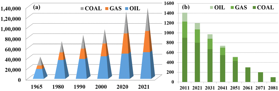 | ||
| Fig. 1 (a) Global consumption rate of fossil fuel has increased and (b) fossil fuel levels are degrading day by day and are currently low (energy consumption in Terawatt-hours on the y-axis).2 Adapted from Open Access data under the Creative Commons BY license. Copyright 2022 Global Change Data Lab. | ||
A growing population means more vehicles causing higher fossil fuel emissions that result in numerous deaths worldwide. One potential solution to mitigate these issues is to reduce the use of oil based engines and transit towards electric vehicles (EVs). EVs are designed to minimize the use of fossil fuels and becoming a hot topic of research due to its pollution-free nature, low maintenance requirements and numerous other advantages. However, it should be noted that powering EVs with fossil fuels still contributes to pollution:3
• 65% emission of carbon dioxide (CO2), one of the main greenhouse gases.
• 16% emission of methane that causes cardiovascular, respiratory problems, memory loss, depression.
• 2% emission of F-gases (fluorinated gases), the most powerful greenhouse gases.
• 6% emission of nitrogen oxides (NOx), which results the production of ozone and smog when react with sunlight.
• Particulate matter is the major cause of lung cancer and acute respiratory distress.
As mentioned, our increasing population and their demands have led to a continuous rise in energy consumption from 1980 to 2013, increasing from 7300 TW h to 22![[thin space (1/6-em)]](https://www.rsc.org/images/entities/char_2009.gif) 100 TW h, and the trend has continued.4 According to a report by the International Energy Agency,5 energy consumption almost doubled between 2010 and 2018. Various industries are actively working towards increasing the production of electric vehicles in the market, recognizing its potential as the next generation of vehicles. In 2017, there was a significant increase in EV sales, reaching nearly 200000 units, which is impressive compared to traditional oil-based engine sales.
100 TW h, and the trend has continued.4 According to a report by the International Energy Agency,5 energy consumption almost doubled between 2010 and 2018. Various industries are actively working towards increasing the production of electric vehicles in the market, recognizing its potential as the next generation of vehicles. In 2017, there was a significant increase in EV sales, reaching nearly 200000 units, which is impressive compared to traditional oil-based engine sales.
Efforts are being made worldwide to ban the sale of gasoline-powered cars, mainly due to environmental concerns and the declining availability of fossil fuels. Many countries, including India, are planning to completely phase out gas and diesel vehicles in the coming decade but its success will depend on the affordability of electric vehicles. The complex components involved in their production and the range of electric vehicles on a single charge can make them expensive, making it difficult for all to afford,6 however, as production increases and competition grows, there is the possibility of cost reduction in the future.
Currently, available electric vehicles in the market are still charged using electricity produced from non-renewable sources, contributing to pollution. Fig. 2 displays global electricity generation from 2015 to 2022 using different sources such as coal, natural gas, nuclear energy, and more.7 Although the usage of non-renewable energy sources has declined in recent years, but are still in use.
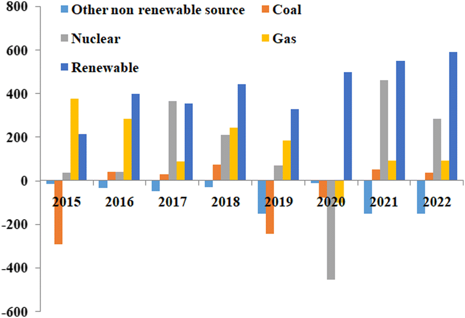 | ||
| Fig. 2 Global electricity generation from different energy sources, including renewable energy sources, from 2015 to 2022.7 Adapted from Open Access data under the Creative Commons BY license. Copyright 2021 International Energy Agency. | ||
With fossil fuel availability diminishing, electric vehicles powered by renewable energy sources like solar energy can be considered as an alternative to conventional gasoline engine vehicles. Solar energy is the most abundant renewable energy source globally, and harnessing it effectively can significantly reduce greenhouse gas emissions and reduce dependence on fossil fuels.
1.1 Solar energy
Relying solely on fossil fuels, will not meet our needs, switching towards renewable energy sources can address the electricity shortage problem, with a clean, pollution-free and abundant source. Among the various renewable energy sources, “solar energy” stands out the most readily available source that can be harnessed to generate electricity for multiple purposes, including charging stations for electric vehicles (EVs).The solar energy spectrum8 encompasses the entire range of electromagnetic radiation, including infrared, visible, and ultraviolet light, as shown in Fig. 3. While it resembles a blackbody spectrum, it can be specifically divided into five regions:
• Ultraviolet C (UVC): ranging from 100 to 280 nm, this high-frequency radiation is mostly absorbed by the Earth's atmosphere, resulting in a minimal percentage of UV rays reaching the surface.
• Ultraviolet B (UVB): ranging from 280 to 315 nm, most of this radiation is also absorbed by the Earth’s atmosphere.
• Ultraviolet A (UVA): ranging from 315 to 400 nm, this region of the spectrum reaches the Earth's surface in significant amounts.
• Visible (VIS): ranging from 380 to 700 nm, all parts of the visible spectrum are received by the Earth.
• Infrared (IR): ranging from 700 nm to 1000000 nm (1 mm), this infrared region is divided into three parts:
(a) Infrared-A: ranging from 700 nm to 1400 nm
(b) Infrared-B: ranging from 1400 nm to 3000 nm
(c) Infrared-C: ranging from 3000 nm to 1 mm
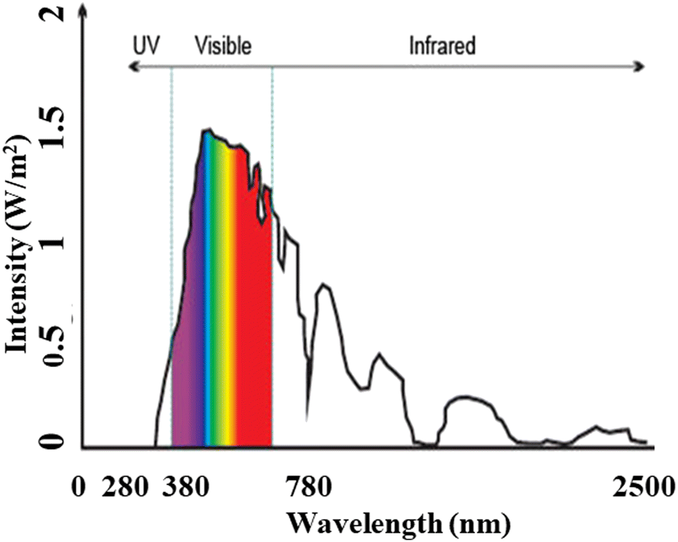 | ||
| Fig. 3 Solar radiation spectrum, similar to blackbody spectrum illustrating the span of electromagnetic radiation. | ||
Solar energy can be converted into electrical energy through two main processes: photovoltaic cells and concentrated power plants. Solar panels primarily convert visible light and a portion of infrared light into electricity, while the remaining energy from the spectrum goes to waste. When comparing various factors such as efficiency, electrical output, capacity utilization factor, net present value (NPV), net capital cost (NCC), levelized cost of energy (LCOE), and payback period for a plant with a capacity of 100 MW, concentrated solar power (CSP) systems exhibit higher efficiency compared to photovoltaic (PV) systems. In terms of electrical energy generation, CSP in its best case scenario outperforms PV as CSP can generate up to 33% more electricity than the best-case scenario of PV.9
1.2 Concentrated solar power plant
CSP plants operate on the basis of the thermal energy storage (TES) principle, which involves conversion of high-temperature thermal energy into power generation which provides a solution to the mismatch timing of solar energy availability and electricity demand.10 Solar energy has the potential to generate a significant amount of electricity if harnessed effectively. Two main methods exist for harnessing solar energy: active solar energy, which involves devices that convert solar energy into other usable forms; and passive solar energy, which focuses on the design, placement, and optimization of materials to maximize the utilization of sunlight, such as in greenhouse structures.11The first CSP plant was established in Italy by Sant'llario in 1968,12 since then, there have been continuous advancements taking place in the field. However, CSP technology is not yet widely used due to its relatively low development compared to other renewable energy technologies. Nevertheless, significant efforts are being made to reduce the dependency on fossil fuels, and many countries, such as Spain and the US, are striving to unlock the full potential of CSP, as illustrated in Fig. 4.13 The global installed capacity of concentrated solar power plants from 2012 to 2019 and the capacity of CSP installations across different countries, highlighting the competition and growth of large-scale commercial CSP projects.14,15
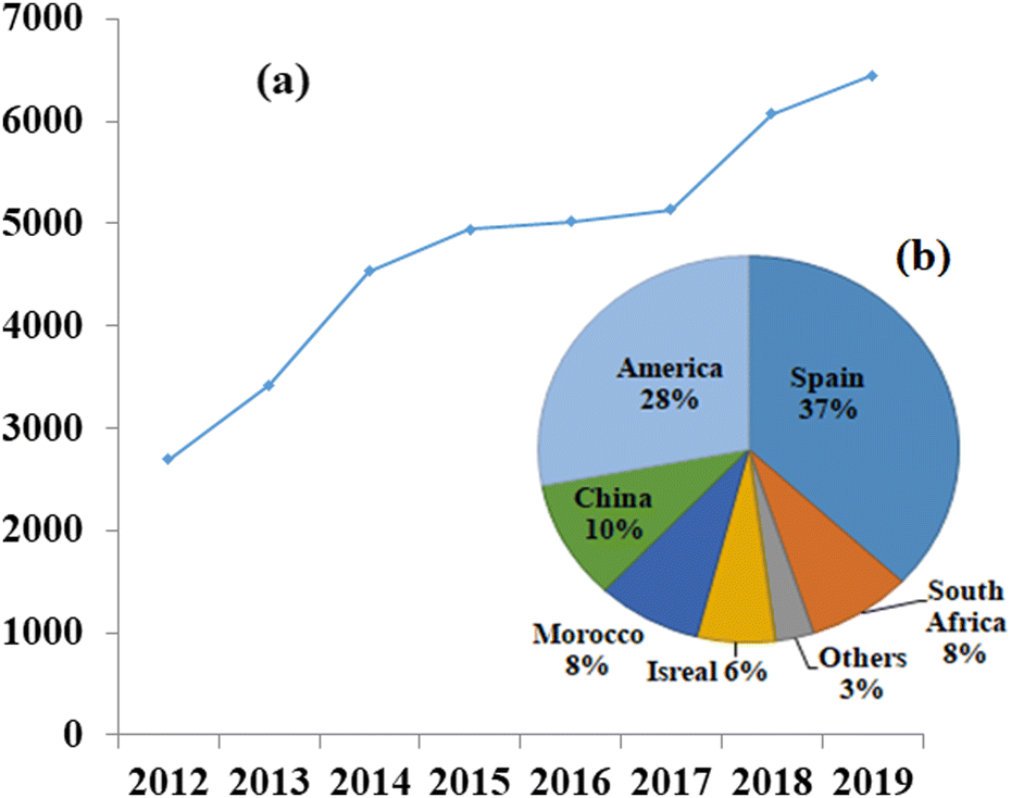 | ||
| Fig. 4 (a) Globally installed capacity of concentrated solar power plants in Megawatts, increasing over the years,13 and (b) contribution of different countries to the overall installation of concentrated solar power plants, with Spain and America leading the way.13 Adapted from Open Access data under the Creative Commons BY license. Copyright 2015 International Energy Agency. | ||
In India, during the first phase of the Jawaharlal Nehru National Solar Mission (JNNSM) from 2010 to 2013, CSP projects with a planned capacity of 470 MW were initiated.16 However, by 2018, only 228.5 MW had been achieved, but efforts are underway in India to generate clean energy and make the country self-reliant in this regard, by setting up a target to achieve 10000 MW of CSP capacity in the coming years.17
1.3 Components of CSP
Considering the value of CSP, many countries are now investing in this technology for electricity generation regardless of the challenges related to reproducibility, sustainability, and efficiency. CSP is a form of passive solar energy that relies on storing thermal energy using heat-storing materials that should possess specific characteristics, such as high thermal conductivity, low density, large heat capacity, a wide range of working temperatures, stability under radiation, and cost-effectiveness.18 Designing an efficient CSP system remains a significant challenge, as it requires considerations of factors such as the levelized cost of electricity (LCOE),19 sustainability, durability, and cost-effectiveness.A CSP system comprises various components, including a solar energy receiver, solar energy storage, a heat exchanger, a turbine, charging stations, and more,20,21 as shown in Fig. 5. Currently, operational CSP plants are expensive and suffer from lower efficiency but could be improved by optimizing various parameters and components within the system.
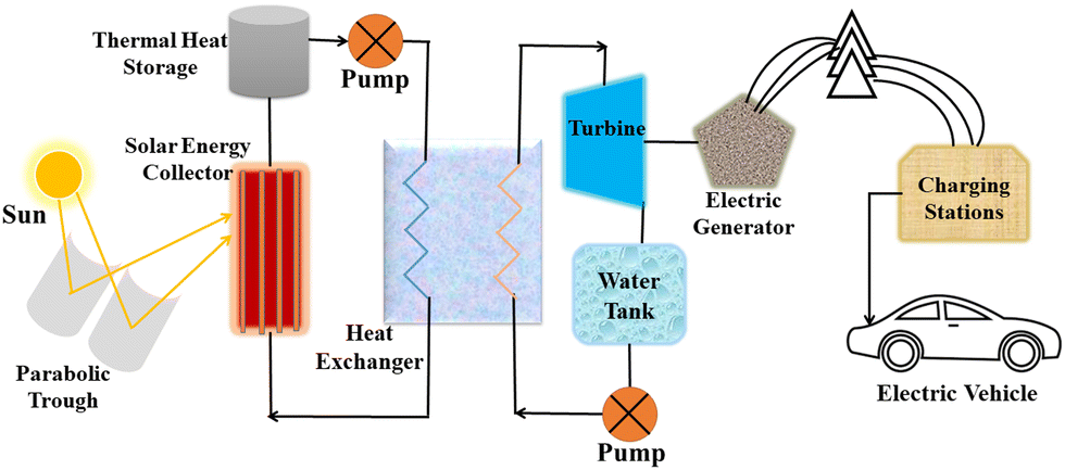 | ||
| Fig. 5 Basic components of a concentrated solar power plant for the storage of thermal energy. | ||
First step for efficiency enhancement is the collection of solar energy with technologies like troughs, linear Fresnel mirrors, or concentrators, as the development level of these technologies directly impacts the system's efficiency.22 Another crucial aspect is the TES material, which allows for the storage of thermal energy and its utilization during periods when the sun is not available, such as rainy days, cloudy days, or at night.
1.4 Thermal energy storage (TES)
TES plays a crucial role in storing solar thermal energy for later use, and different materials can be used, including synthetic oil, molten salt, nanofluids, saturated steam, and ethylene glycol.23,24 Some of these materials are used at an industrial level, while others are still in the research phase.For TES in a CSP, it is essential to use materials that can withstand high temperatures and effectively function within a wide temperature range. Molten salts are phase changing materials at specific temperature, with characteristics such as a low boiling point, a suitable working temperature difference, thermal stability, high thermal conductivity, and low density.25
The low boiling point of molten salts ensures their changing state which can transfer heat at relatively low temperatures.26 A good temperature difference implies a high heat capacity, enabling the capture of significant amounts of thermal energy from the sun. Thermal stability is important to maintain the efficiency and reproducibility of molten salts, preventing evaporation. Therefore, utilizing molten salts in CSP systems can reduce the LCOE,27–29 examples include liquid nitrate and carbonate salts, Hitec and Hitec XL doped with different nanoparticles at varying concentrations. The selection of an appropriate salt for TES depends on its working temperature, density (to avoid issues with viscosity), thermal conductivity, thermal stability, specific heat capacity, etc., and should be sustainable, reproducible and cost-effective.
1.5 Thermophysical properties – thermal conductivity and its importance
To consider such solar salts for thermal energy storage, several thermophysical properties need to be taken into account: thermal conductivity, specific heat capacity,29 viscosity, stability, working temperature and corrosion resistance. Among these factors, thermal conductivity is of utmost importance in solar thermal energy storage systems as it is the cause of low efficiency in current CSP systems, and is caused by different factors, including density, moisture content, temperature and fluidity.The thermal conductivity of solar salts is not particularly high, but by incorporating nanoparticles into solar salts, their conductivity can be enhanced, as shown in Fig. 6. When materials are reduced to the nanoscale, they exhibit fascinating properties such as photothermal and photoconductive behavior, as well as other attractive characteristics related to light: electricity, magnetism and catalysis. Nanoparticles of different metal oxides – such as Al2O3, TiO2, ZnO, CuO, MgO – have been used to enhance the thermal conductivity of solar salts in different domains.
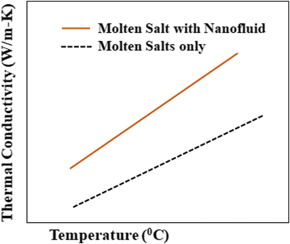 | ||
| Fig. 6 Elevation in thermal conductivity after addition of nanoparticles to a molten salt. Adapted from ref. 40, with permission from AIP Publishing, Copyright 2017. | ||
Al2O3 nanoparticles, with their spherical morphology and hexagonal structure, have been added to solar salts, resulting in an 8.3% increase in thermal conductivity at a temperature of 400 °C, depending on the shape, size, and concentration of the nanoparticles.30 TiO2 nanoparticles, which can exist in different structures (anatase, rutile, and brookite) depending on temperature, can enhance thermal conductivity by 8.1% when added to solar salts at particular concentrations.30 The addition of ZnO nanoparticles to solar salts has not been extensively studied, but it has been observed that their incorporation with water increases thermal conductivity.31 CuO nanoparticles, with their monoclinic structure,32 exhibits the excellent heat and electricity conductivity and act as a p-type semiconductor with a band gap of 1.2 eV.33 When nanoparticles of CuO are added to the base fluid, thermal conductivity of the mixture increases by approximately 30% at a volume concentration of 2%.34 Adding MgO nanoparticles to solar salt shows an enhancement of 62.1% at 5.0% concentration,35 but slightly increases the density of the nanofluid. Besides metal oxide nanoparticles, carbon nanotubes (CNTs)36 are gaining more attention due to their high thermal conductivity between 1100 W m−1 K−1 to 7000 W m−1 K−1.37 Therefore, adding CNTs to solar salt could improve its thermal conductivity extensively.38,39
As mentioned earlier, the thermal conductivity of solar salts is crucial for efficient heat transfer. However, their thermal conductivity falls between 0–1 W m−1 K−1 in liquid and in the solid state, which limits their heat transfer efficiency. Therefore, by incorporating nanoparticles the thermal conductivity of solar salts can be enhanced, resulting in increased efficiency and cost reduction.
2 Historical development
The historical understanding of thermal conductivity can be traced back to the 18th century when scientists began the study of heat. In 1686, Daniel Fahrenheit invented the mercury thermometer, which sparked interest in the study of heat.41 Prior to that, Guillaume Amontons proposed a theory about the flow of heat in the direction of decreasing temperature in a linear manner, although without any proof or experimental results. In 1761, Joseph Black introduced the concept of latent heat (the heat required to change the state of a substance) and specific heat (the quantity of heat required by a unit mass to raise its temperature by 1 °C), which laid the foundation for the concept of heat storage. Antoine Lavoisier and Pierre Simon Laplace demonstrated constancy of the latent heat of melting ice through the invention of the calorimeter.42 In 1776, Johann Heinrich Lambert advanced the study of heat movement by conducting experiments using a metal rod to study the linear temperature profile.43 However, the results showed that the temperature decreases logarithmically along the rod, which may have been due to the specific shape and material of the rod not being taken into account.Benjamin Franklin (1706–1790)44 carried out experiments to determine the relative heat conducting abilities of different metals using wax. He coated the metals with wax and uniformly heated them to observe at what distance the wax would melt for each case. Further experiments by Igen Housz (1730–1794)45 involved seven different metals of the same length and diameter, leading to the conclusion that different materials have different tendencies to conduct heat. His experiments also revealed that thermal conductivity in crystals is direction-dependent.
Count Rumford studied the relative insulating properties of various materials such as cotton, silk, wood, fur and down.46 He used a thermometer placed in a glass bulb filled with the material of interest (e.g., air, water, mercury) and immersed the apparatus in hot and cold water to establish temperature–time correlations, which allowed for the measurement of thermal conductivity.
By the end of the 18th century, a complete explanation of thermal conductivity had not yet been established. In 1802, Fourier studied heat diffusion and built upon the research of Jean-Baptiste Biot,47 who had focused on the heat conduction differential equation. Biot's work was based on Newton's law of cooling, which was derived for the case of radiative heat loss rather than conductive loss. So the idea of directly continuing Biot’s work was dropped by Fourier who further formulated thermal conductivity using a boundary condition at the radiative surface, as given in eqn (1),
| hT= −κ/dT/dx. | (1) |
 represents the temperature gradient. However, no devices or experiments were available at the time to directly measure heat flow, Fourier had to devise experiments to calculate thermal conductivity based on whether temperature is a function of heat or not. Subsequently, various experiments were conducted to determine the relative thermal conductivity of different materials and the absolute thermal conductivity after a specific stage was set by Fourier.48
3 Thermal conductivity analytics
Thermal conductivity is a material property that determines how well a material conducts heat, commonly represented by the symbol ‘k’, but in some books and literature, it is also denoted by ‘λ’ or ‘κ’; the inverse of thermal conductivity gives thermal resistivity. Materials with high thermal conductivity are often used in heat sinks as they can efficiently absorb and transfer heat energy to the environment. Many experiments have been conducted to develop devices that can precisely measure the thermal conductivity of materials. In 1807 to 1811, Joseph Fourier designed a device and formulated a mathematical expression that provides a good estimate of thermal conductivity. Fourier's law of thermal conduction (also known as the law of heat conduction),47 as described by eqn (2), states that the rate of heat transfer through a material is proportional to the negative gradient of temperature and the area of heat flow.| q = −κ·∇T | (2) |
Mathematics:
Consider a material in which the flow rate of heat is  through a cross-sectional area represented by A. Initially, at a distance x, the temperature is denoted as T, and after some time, at a distance x + ∇x and temperature T + ∇T. Heat flows in the positive direction, the temperature gradient must be negative, as heat flows from higher to lower temperatures, as shown in Fig. 7.
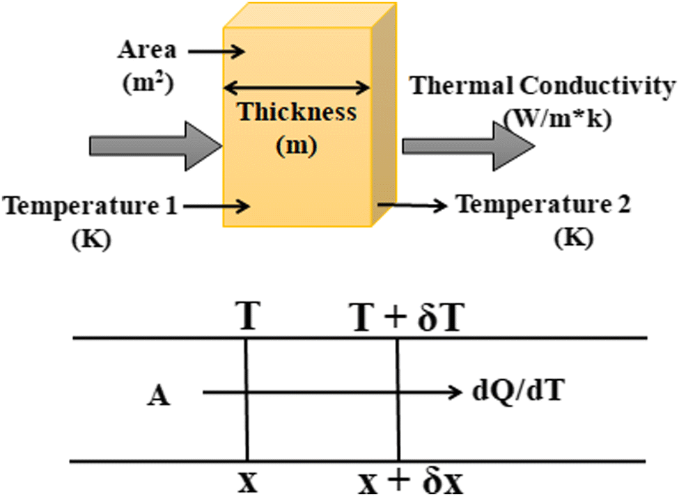 | ||
| Fig. 7 A typical heat flow mechanism inside the conductor. | ||
Now, the thermal conductivity κ can be defined as the ratio of heat flow rate per unit area to the negative of the temperature gradient. It can be written as in eqn (3):
| dQ/dt = κ·A·(dT/dx) | (3) |
Units:
• Fundamental units of thermal conductivity can be: temperature, length, mass and time.
• It can also be written as power/(length × temperature).
• Watts per meter-Kelvin (W m−1 K−1) is the standard unit of thermal conductivity.
• These units relate heat conduction rate for a unit thickness of a material, for each Kelvin of temperature difference.
Discussion so far considers a one-dimensional situation in an isotropic medium, where all properties are uniform and independent of direction. In such a scenario, heat flow is opposite to the temperature gradient. However, in an anisotropic medium, where properties vary with direction, the heat flow rate and the temperature gradient can differ along different axes of the crystal. In that case, the heat flow may not strictly be antiparallel to the temperature gradient, and thermal conductivity becomes a tensor quantity.
3.1 Thermal conductivity in different states
Matter is composed of extremely small particles that cannot be seen with the naked eye, and is classified into four states – solid, liquid, gas, and plasma – but for the purpose of discussion here only three states (excluding plasma) are considered. The thermal conductivity of a material49 varies depending on its state whether it is solid, liquid, or gas state. This variation is due to the differences in intermolecular spacing: the molecules in a liquid are further apart from each other than in a solid, and move in a random manner due to the larger intermolecular spacings. This random movement hinders the efficient conduction of heat, resulting in a decrease in thermal conductivity in liquids.Thermal conductivity is directly proportional to the mean molecular speed and mean free path.50 The mean free path depends on the diameter of the molecule, where larger molecules have a higher probability of collisions compared to smaller molecules. Light gases like hydrogen and helium have high thermal conductivity, whereas denser gases like xenon and dichlorodifluoromethane have low thermal conductivity due to hindered molecular movement. Additionally, the thermal conductivity of gases generally increases with temperature.
When comparing liquids to gases, liquids tend to have better thermal conductivity and with their fluidity properties, they are suitable to use as heat sinks. Liquids can absorb heat and effectively transfer it through the heat sink, acting as heat transfer agents but for non-metallic liquids, the thermal conductivity tends to decrease with increasing temperature. It is important to note that thermal conductivity cannot be generalized for all liquids, as it depends on the specific properties of each liquid.
3.2 Thermal conductivity of solar salts with nanoparticles
Molten salts undergo a phase change from solid to liquid when their temperature is increased, making them suitable for use as thermal energy storage media. However, the thermal conductivity of molten salt is not sufficiently high, an important characteristic for an applicable thermal energy storage material, addition of selected nanoparticles to molten salt could resolve this, as illustrated in Fig. 8. Among the molten salts, solar salt stands out due to its favorable thermophysical properties, affordability and availability in the market, as seen in Table 1, having significant potential for incorporation in CSP systems.51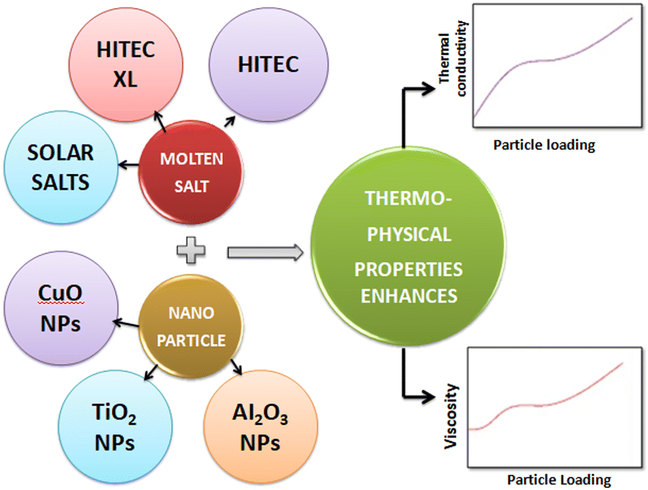 | ||
| Fig. 8 Addition of nanoparticles to molten salt, elevating their thermophysical properties for use as thermal energy storage materials. | ||
| No. | Salt | Composition (wt%) | T. C. (W m−1 K−1) | Cost (Rupees per kg) |
|---|---|---|---|---|
| 1 | Solar salt | NaNO3–KNO3 | 0.52 | 37.30 |
| 2 | Hitec | NaNO3–KNO3–NaNO2 | 0.33 | 70.78 |
| 3 | Hitec Xl | NaNO3–KNO3–Ca(NO3)2 | 0.52 | 108.82 |
| 4 | Therminol VP-1 | Biphenyl–diphenyl oxide | 0.090 | 301.36 |
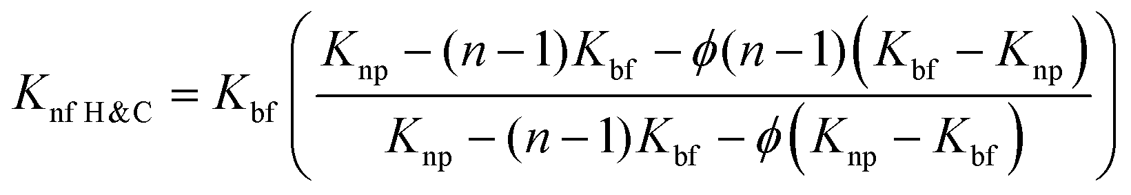
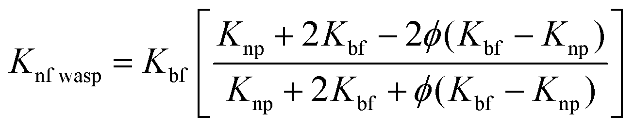
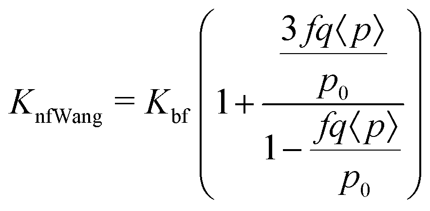
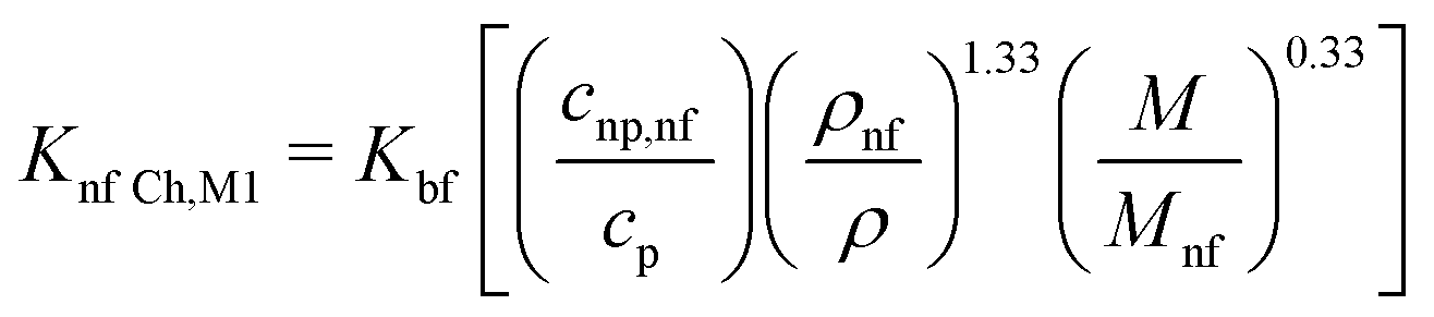
Extensive research has been conducted to investigate how the addition of nanoparticles and other parameters can enhance thermal conductivity. Several models have been proposed to explain the behavior of nanofluids, which are a weighted average of nanoparticles and base fluids, and their contribution to thermal conductivity.54 These models incorporate various factors such as the diameter of the base fluid, sphericity of nanoparticles, viscosity, temperature, volume fraction, nanolayer thickness, and so on. Maxwell was the first to propose a model predicting the thermal conductivity of nanofluids,55 which considered spherical bodies in low concentrations. In this context of nanofluids, the thermal conductivity is typically denoted as κ, but for ease of understanding, we will use K in this discussion. Different suffixes and prefixes are employed to represent the thermal conductivity of different fluids.
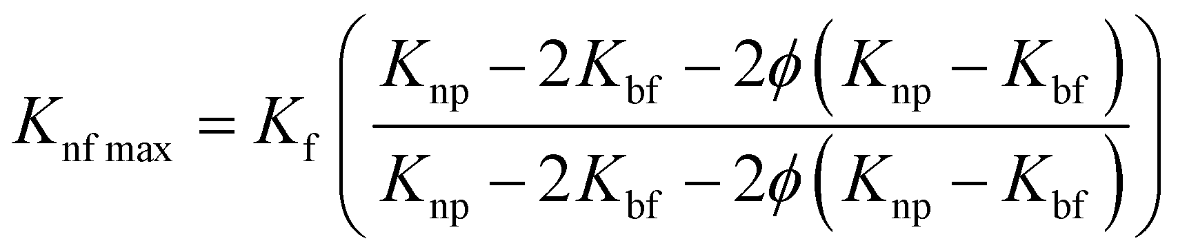 | (4) |
 | (5) |
| n = 3/w. | (6) |
 | (7) |
 | (8) |
None of these models consider the random movements of particles in the fluid due to Brownian motion, and are hence considered to be static models. Dynamic models have also been developed that include the viscosity, temperature, size and distribution, layer thickness, cluster formation etc., by which the thermal conductivity of nanofluids is affected. A dynamic model (eqn (9)) was given by Xuan et al.58 using the Maxwell model55 as a baseline and adding the other factors also.
| KnfXuan = Knfmax + 1/2ρnpcnpϕ(2DB)1/2 | (9) |
| DB = kBT/6πμbfrc | (10) |
The Kleinstreuer model59 again uses the Maxwell model55 as a base model and adds other dynamic factors that affect the thermal conductivity. These include volume fraction, types of particle, temperature and also the properties of the basefluid. It considers function f, that depends on these various factors, as given in eqn (11),
 | (11) |
 | (12) |
 | (13) |
| KnfP&C = 1 + 7.47ϕ. | (14) |
The next model was given by Timofeeva et al.64 and also includes agglomeration factors. The thermal conductivity model predicted is given by eqn (15),
| KnfTim = Kf(1 + 3φ). | (15) |
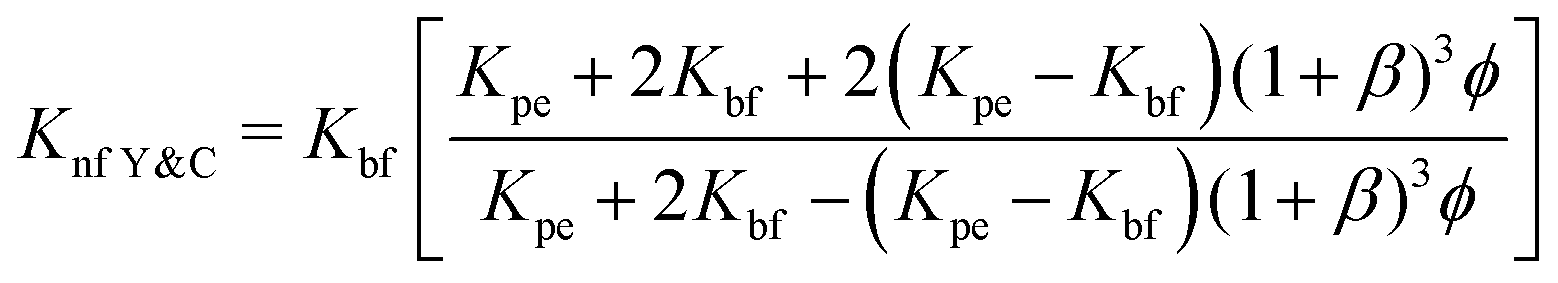 | (16) |
 | (17) |
 | (18) |
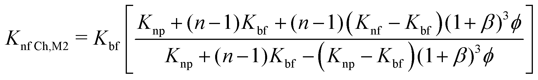 | (19) |
Another empirical model68 predicted by Corcione et al. (eqn (20)) includes factors of dynamic viscosity of the nanofluids, volume fraction, temperature but only for the range 294–324 K, and diameter of nanoparticles in the range 10–150 nm. This type of specified model is very beneficial from an engineering point of view for thermal design tasks:
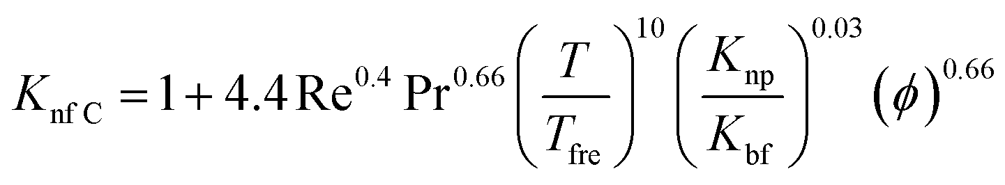 | (20) |
4 Factors affecting thermal conductivity
Various factors affect the thermal conductivity of a material, including its structure, density, phase, composition and temperature, and can be intensive or extensive in nature. The thermal conductivity also differs between metals and non-metals due to their distinct characteristics, which are also influenced by various factors.4.1 Effect of temperature
The behavior of thermal conductivity with temperature depends on whether the material is a metal or a non-metal, as each behaves differently in response to temperature changes.• According to the Wiedemann–Franz law, thermal conductivity is directly proportional to temperature and electrical conductivity.
• When the temperature increases, the electrical conductivity of a pure metal decreases due to electron collisions.
• This implies that the thermal conductivity of a pure metal varies slightly with increasing temperature and abruptly decreases when the temperature reaches 0 K.
• Alloys, on the other hand, exhibit less change in electrical conductivity, resulting in an increase in thermal conductivity with temperature.70
• In non-metals, thermal conductivity is mainly attributed to lattice vibrations that carry energy in the form of phonons due to scarcity of free electrons.
• As phonons travel and collide with each other they experience a mean free path that does not significantly change with temperature. This indicates that the thermal conductivity of non-metals remains largely unaffected by higher temperatures.
• Below the Debye's temperature,70 both the thermal conductivity and heat capacity of non-metals decrease.
4.2 Other factors that affect thermal conductivity
Variations in thermal conductivity can be attributed to several factors, including thermal anisotropy, electrical conductivity, magnetic fields, and more. The influencing factors of thermal conductivity in substances are illustrated below.• Phase change of material: changing the phase of a material results in abrupt changes in thermal conductivity. For example, water exhibits this dependency, where the thermal conductivity of ice71 is 2.18 W m−1 K−1 and changes to 0.56 W m−1 K−1 in the liquid phase.
• Thermal anisotropy: crystals have different planes, and as a result, the physical properties of crystals vary across these planes. It is possible that phonons along a specific plane are coupled differently to phonons in other planes of the same crystal. Thus, the thermal conductivity varies due to thermal anisotropy, which means that the direction of the temperature gradient may not align with the direction of heat flow.
• Influence of magnetic fields: the Maggi–Righi–Leduc effect72 describes the change in thermal conductivity of a conductor when subjected to an applied magnetic field, which causes formation of an orthogonal temperature gradient, that can be responsible for alterations in thermal conductivity.
• Isotopic purity of the crystal: while thermal conductivity is an intensive property, the addition of impurities decreases its value. For instance, in type IIa diamond, a 98.9% concentration of carbon-12 results in a thermal conductivity of 10000 W m−1 K−1, whereas a 99.9% enriched diamond exhibits a thermal conductivity of 41000 W m−1 K−1.73
4.3 Factors affecting the thermal conductivity of nanoparticles
It has been established that the thermophysical properties of bulk matter differ from nanoparticles. Various factors that affect the thermal conductivity of nanoparticles69 are listed below.• Numerous experiments have demonstrated how different nanoparticles of different shapes and size affect the thermal conductivity. Ambreen and Kim et al.74 showed that reducing nanoparticle size increases the effective surface area, enhancing Brownian motion and leading to an increase in thermal conductivity. Subsequently, Xu et al.75 and Anoop et al.76 conducted different experiments and showed that different shapes of nanoparticles, such as spherical, cylindrical, rod, banana-shaped, nearly-rectangular, brick, platelet, and blade shapes, have an impact on thermal conductivity.
• Thermal conductivity also depends on the base fluids and the concentration of nanoparticles. Increasing the concentration amplifies the interfacial area between the base fluid and the nanoparticles, resulting in an increase in thermal conductivity.77
• Thermal conductivity also depends on agglomeration of NPs, as it provides an extra conduction path to the nanofluids, but excessive agglomeration can lead to sedimentation, creating difficulties for fluid to flow.78,79
• Different experiments have been done to confirm if the thermal conductivity of nanoparticles depends on temperature. Chon et al.80 and Mintsa et al.81 showed that it is independent of temperature, but some experiments showed an inverse relation with temperature, like the experiment carried out by Duangthongsuk and Wongwises82 for water-based TiO2 nanofluids.
• The pH of nanofluids is a crucial factor that directly or indirectly affects thermal conductivity by influencing the degree of nanoparticle aggregation, zeta potential, particle size distribution, rheology, viscosity, and stability, all of which impact the thermal conductivity of nanofluids.83
• When a strong magnetic field is applied, small-dimensional particles form chains that tend to align with the direction of the magnetic field observed in experiments.84 The alignment of particles promotes heat transfer capability and lead to an increment in thermal conductivity.85
• Sonication also plays an important role. Decreasing sonication time reduces the probability of sedimentation and enhances Brownian motion, ultimately increasing the thermal conductivity of nanofluids. However, excessive sonication time can have a reverse effect on thermal conductivity.86,87
5 Experimental techniques
Thermal conductivity is enhanced by the addition of nanoparticles to solar salts, making it an important factor in the operation of CSP systems. Solar salts typically have low thermal conductivity, but inclusion of nanoparticles can improve. Different methods are available for the synthesis and mixing of nanoparticles with solar salts, as well as various techniques for measuring the thermal conductivity of nanofluids.The current methods for measuring thermal conductivity can be categorized based on their temperature dependence. Fig. 9 illustrates the various methods used to approximate thermal conductivity, primarily falling into three types: transient methods (where temperature changes with time), steady-state methods (where temperature remains constant and heat transfer is characterized by a constant, specific heat transfer), and the thermal comparator method (a relative method that uses a calibration curve to determine the value of the unknown parameters).88
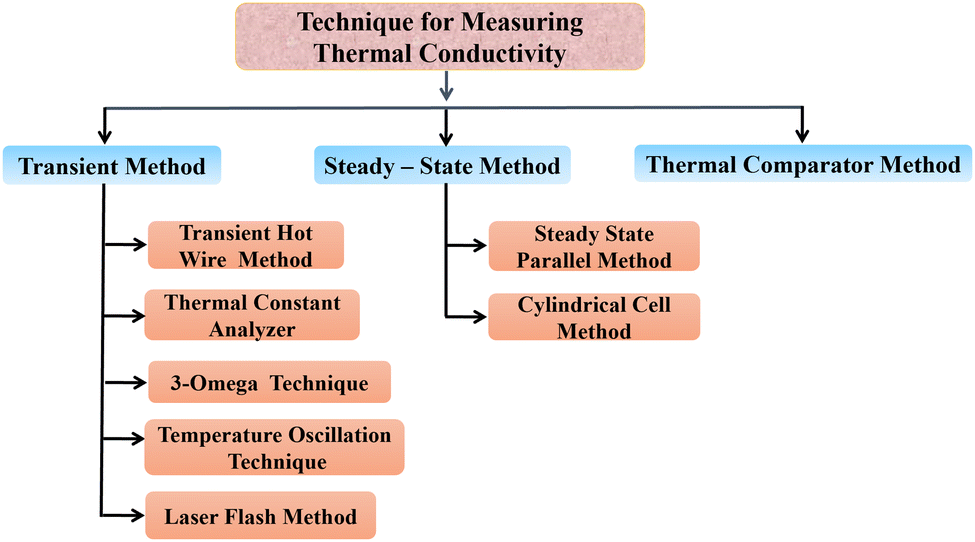 | ||
| Fig. 9 The different techniques for measuring the thermal conductivity of nanofluids. | ||
5.1 Transient hot wire method
Stalhane and Pyk proposed the transient hot wire method in 1932 as discussed by Horrocks et al.89 which is used to measure the thermal conductivity of nanomaterials where solar salts are used as the base fluid and nanomaterials are additives with temperature-dependent thermal conductivity. This method involves a thin wire, typically made of platinum or tantalum, which serves as both a sensor and a heat sink submerged in a sample cell filled with the test fluid, as shown in Fig. 10. Applying a specific voltage across the thin wire, heat is generated and transferred to the surrounding fluid at a rate dependent on the thermal conductivity of the liquid.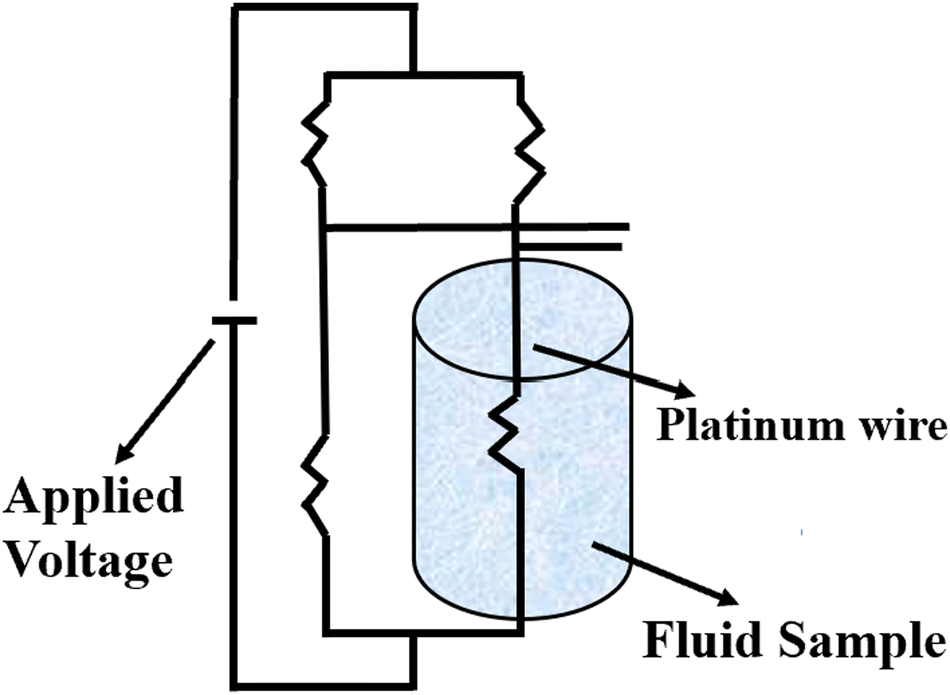 | ||
| Fig. 10 Schematic diagram of the transient hot wire method. Adapted from ref. 69, with permission from MDPI, Copyright 2021; and ref. 91 with permission from Elsevier, Copyright 2020. | ||
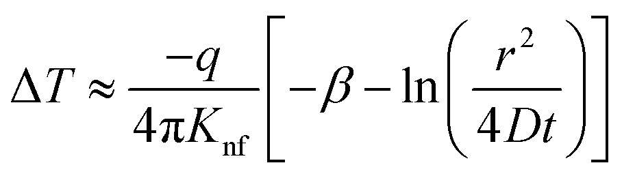
As the heat is transferred, the changes in resistance can be correlated with the variations in temperature, allowing for the calculation of thermal conductivity. According to Carslaw and Jaeger,90 the relationship between change in temperature with time can be described by eqn (21),
 | (21) |
 | (22) |
 | (23) |
 | (24) |
5.2 Thermal constants analyzer
The thermal constants analyzer technique is utilized to determine the thermal conductivity of nanofluids by employing a transient plane source based on Fourier's law of heat conduction. The setup consists of a thermal constants analyzer, a vessel, a constant temperature bath, and a thermometer, as depicted in Fig. 11. The probe is immersed in the vessel containing the nanofluid, which is then placed in the constant temperature bath. The thermometer is used to measure the temperature of the nanofluid.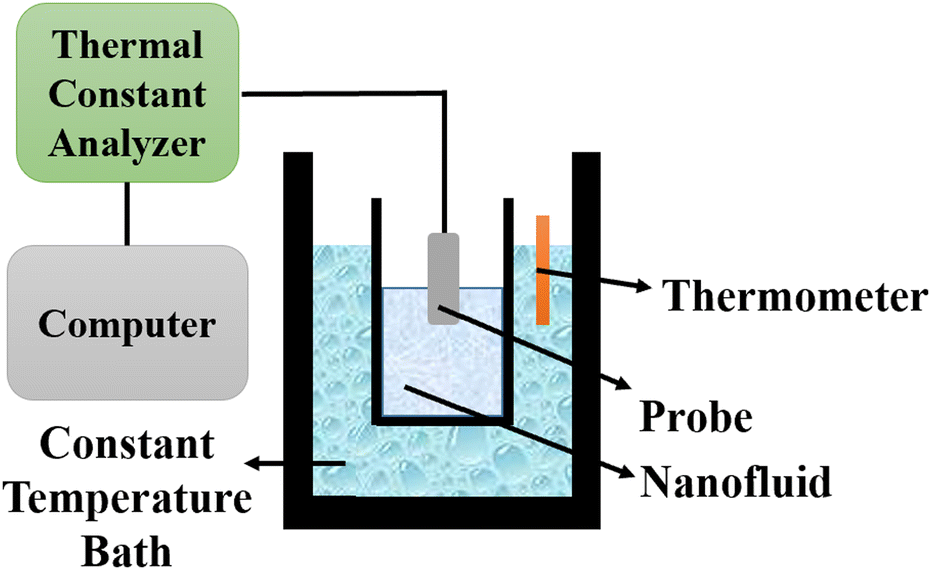 | ||
| Fig. 11 Schematic diagram of a thermal constants analyzer. Adapted from ref. 69, with permission from MDPI, Copyright 2021; and ref. 91 with permission from Elsevier, Copyright 2020. | ||
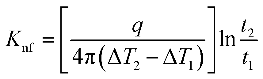
The probe utilized in this technique should comprise a thin foil made of an electrical conducting material, which is responsible for generating the heat. By applying Fourier's law of thermal conductivity and utilizing the relationship between resistance and temperature, described by eqn (25),92 the thermal conductivity of the nanofluid can be determined,
 | (25) |
 | (26) |
 | (27) |
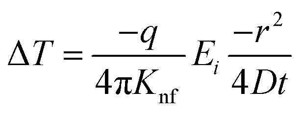
5.3 3-Omega method
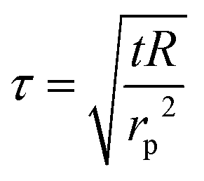
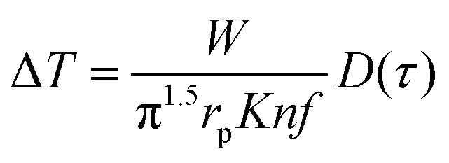
This method was initially developed for measuring the thermal conductivity of bulk materials and has been subsequently adapted for nanofluids and thin films.94 It involves the application of sinusoidal current with a frequency ω across the sample using a metal wire heater which is similar to the hot wire method, where the sample element serves as both the heater and the thermometer. The applied current at frequency ω generates heat at a frequency of 2 − ω, and the corresponding voltage is measured at 3 − ω. The thermal conductivity can be determined using eqn (28),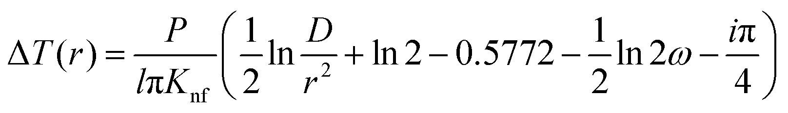 | (28) |
 represents the amplitude of the power per unit length generated at a frequency 2 − ω, D is the thermal diffusivity, and r is the distance. Hence thermal conductivity (Knf) can be measured using the real or imaginary part of the given equation. For more detail, one can look into the paper by Cahill et al.95
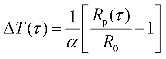
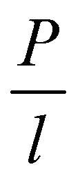
5.4 Temperature oscillation technique
The temperature oscillation technique is employed initially to measure the thermal diffusivity, then it is used for the calculation of thermal conductivity. A nanofluid is used to fill the cylindrical volume, and temperature oscillations are applied where amplitude and phase of the temperature oscillations are determined by selecting reference and end points, as shown in Fig. 12.96 It has been demonstrated that thermal diffusivity can be accurately measured using the amplitude attenuation of thermal oscillations. Therefore, by calculating the density and specific heat using eqn (29), the thermal conductivity can be determined using a principle first utilized by Das et al.97 for nanofluid comprising nanoparticles of Al2O3 and CuO in water,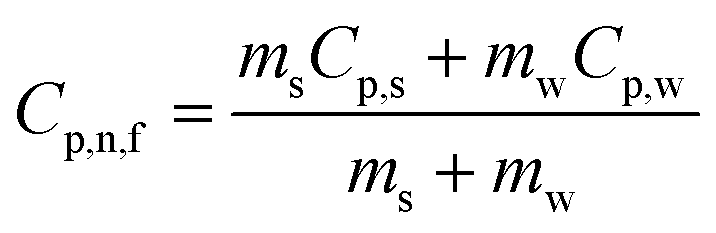 | (29) |
| Knf = αnfρnfCp,nf. | (30) |
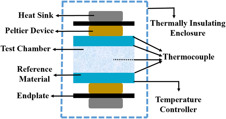 | ||
| Fig. 12 Schematic diagram of the temperature oscillation technique. Adapted from ref. 96, with permission from Elsevier, Copyright 2021. | ||
5.5 Laser flash method
The laser flash method was developed to determine the thermal diffusivity, which is subsequently used to calculate thermal conductivity. In this method, a short laser pulse is applied to heat up a specific region of the specimen, either at the lower or upper part, while the change in temperature is recorded using an infrared detector.98 The laser pulse is directed towards a disc-shaped sample containing nanoparticles, as illustrated in Fig. 13. The thermal diffusivity (α) can be calculated using eqn (31),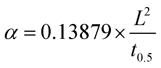 | (31) |
| K = α × ρ × Cp | (32) |
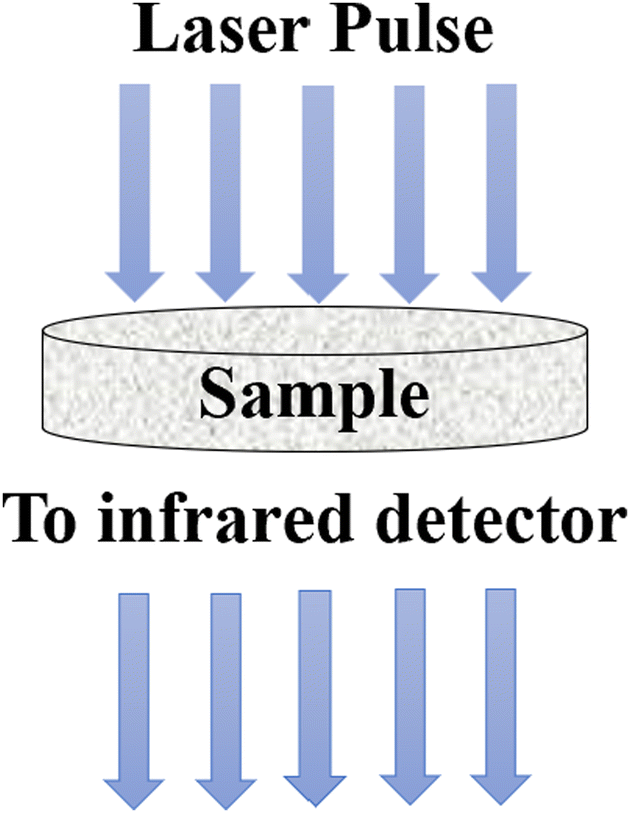 | ||
| Fig. 13 Schematic diagram of the laser flash method. Adapted from Open Access data under the Creative Commons BY license from ref. 69, Copyright 2021 MDPI. | ||
5.6 Steady-state parallel plate method
Different structures can be utilized to estimate the thermal conductivity of nanofluids based on steady-state heat conduction, where the temperature difference is constant. Two preferred structures for heat transfer measurement are the parallel plate and concentric cylindrical cells, employing the concept of heat conduction in a single direction and thermal resistance.In the parallel plate experimental setup, a sample is inserted between copper plates, and a main heater supplies heat. After a certain time, a steady temperature is achieved by the upper and lower copper plates, allowing the calculation of the sample's thermal conductivity given a detailed description by Wang et al.99 The schematic diagram of the technique is shown in Fig. 14 where another heater had been used to maintain the inner environment for the prevention from heat loss. This method was used to calculate the thermal conductivity of alumina and copper oxide-based nanofluids and the heat conduction in a single direction can be calculated using eqn (33),
 | (33) |
 | (34) |
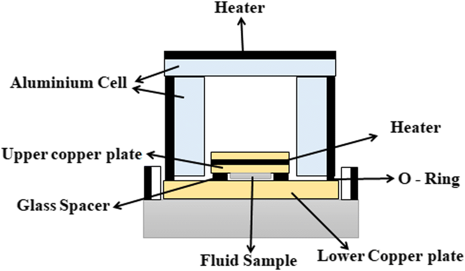 | ||
| Fig. 14 Schematic diagram of the steady-state parallel plate method. Adapted from ref. 100, with permission from IOP Science, Copyright 2017. | ||
5.7 Cylindrical cell method
The cylindrical cell method uses two concentric cylinders, similar to the parallel plates in the steady-state parallel method. A detailed description of this method can be found in the work by Kurt and Kayfeci,101 and the schematic diagram is shown in Fig. 15.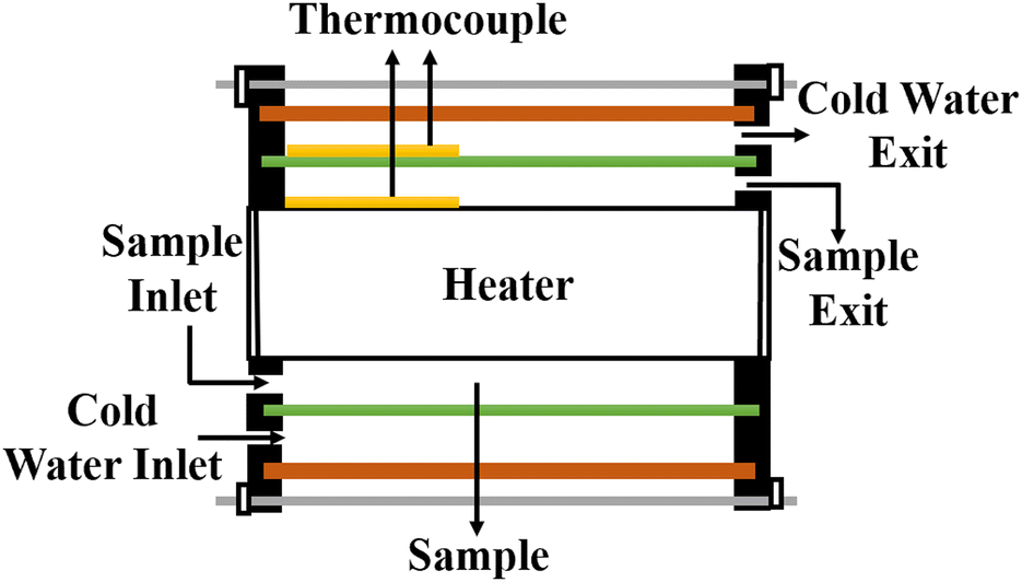 | ||
| Fig. 15 Cross-section of the cylindrical cell method. Adapted from ref. 101, with permission from Elsevier, Copyright 2009. | ||
In this setup, a sample fluid is inserted inside the coaxial cylinder, and an electrical heater is positioned inside the cylinder to heat it up. As the temperature of the inner cylinder increases, heat flows radially outwards through the sample, which fills the annular gap between the cylinders. Two calibrated thermocouples are used to measure the outer surface temperature Ti of the glass tube and the inner cylinder temperature T0. The thermal conductivity can then be calculated using eqn (35),
 | (35) |
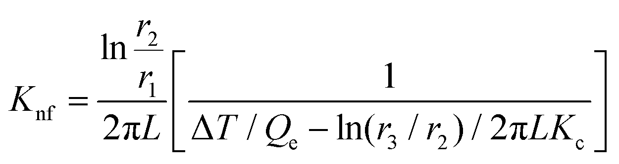
5.8 Thermal comparator method
The indirect technique, proposed by Powell et al.,102 is based on the principle of heat transfer from a hotter material to a colder one when they are brought into contact over a small area. The setup for this technique is shown in Fig. 16. The establishment of thermal equilibrium depends on the thermal conductivity of both materials involved. In this method, one material with a known thermal conductivity is chosen, while the other material has an unknown thermal conductivity where heat transfer occurs under steady-state conditions. Considering the flow of heat in semi-infinite bodies with the boundary conditions 0 < z < ∞ and −∞ < z < 0, having an initial temperature T0 for the material with a known thermal conductivity K1, and an unknown temperature T1 for the material with thermal conductivity K2. By considering the boundary conditions, the relationship can be expressed as eqn (36),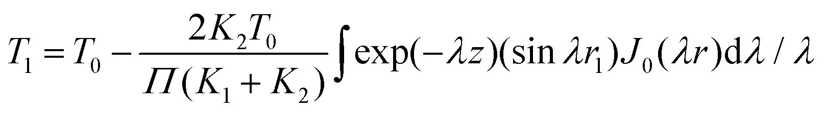 | (36) |
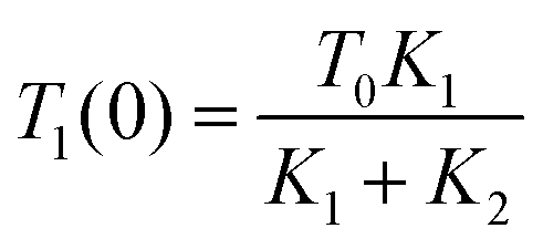 | (37) |
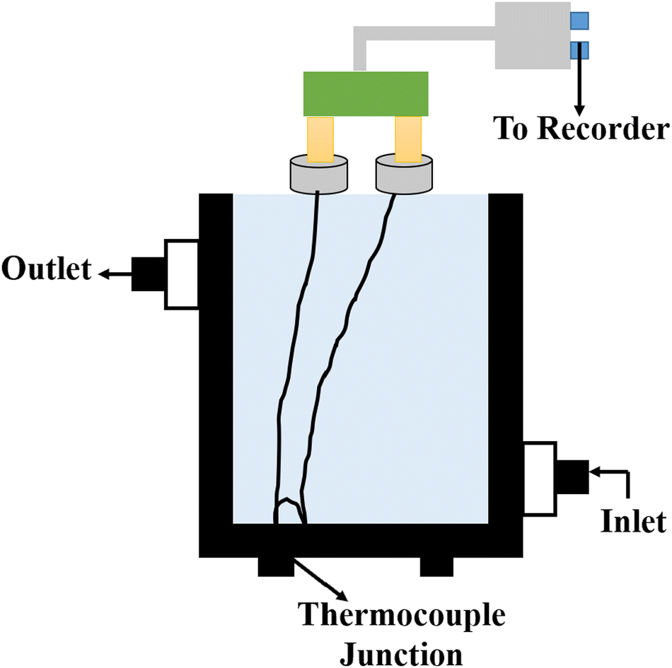 | ||
| Fig. 16 Schematic diagram of the thermal comparator method. Adapted from ref. 103, with permission from the American Chemical Society, Copyright 1983. | ||
6 Discussions and experimental results
Various approaches have been employed over the years for measuring the thermal conductivity of nanofluids, with some methods considered more sophisticated and widely accepted as standard. However, all of these methods share a common challenge: the measurements are highly sensitive to initial conditions, where minor changes can significantly impact the results. Measuring the thermal conductivity of nanomaterials is not an easy task, primarily due to the requirement for sample stability, which is influenced by factors such as material composition, temperature, and the concentration of the BF and NPs. Research has revealed that achieving sample stability can take up to a month, and ongoing maintenance is necessary to prevent sedimentation of nanoparticles.104 Among the various measurement techniques reviewed, the transient hot wire method (Section 5.1) stands out as the most commonly used approach which offers good accuracy, requires no calibration, and is a simple experiment with low cost.105,106 Here, we provide an overview of experimental results using the laser flash method.SEM of CuO in solar salt is shown in Fig. 17. The small and dark spots are the CuO particles spread in the salt where agglomeration of CuO particles happens in the order 100–300 nm, which is the result of natural convection taking place in the liquid phase of the salt. These particles are distributed very well in the salt and can be seen by visual inspection.
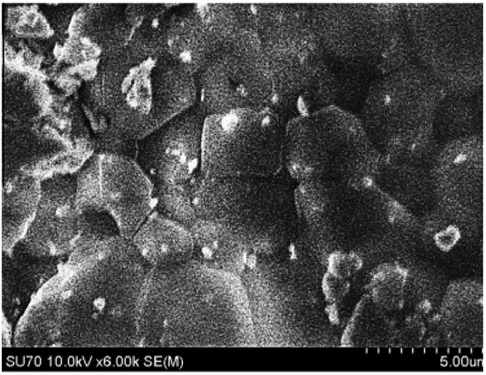 | ||
| Fig. 17 SEM of CuO in solar salt. Adapted from ref. 34, with permission from Elsevier, Copyright 2016. | ||
The thermal conductivity can be calculated using thermal diffusivity measured using the laser flash method (Section 5.5). The thermal conductivity results of CuO nanoparticles in solar salt are shown in Fig. 18, where incremental changes in thermal conductivity occur after mixing 2% by volume of CuO in pure NaNO3–KNO3 at different temperatures. Different concentrations of CuO nanoparticles enhance the thermal conductivity, although this is not significant at higher concentration due to the large error measurements.34
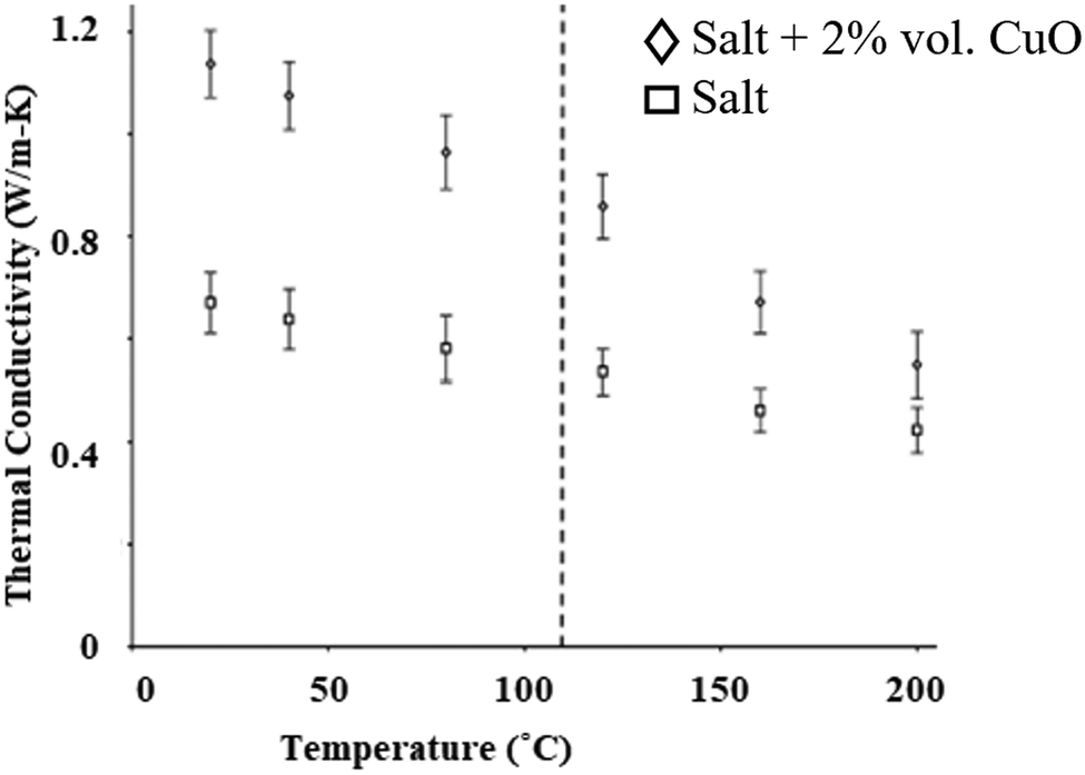 | ||
| Fig. 18 Experimental data showing elevation in thermal conductivity before and after addition of CuO nanoparticles to NaNO3–KNO3. Adapted from ref. 34, with permission from Elsevier, Copyright 2016. | ||
The thermal conductivity of Al2O3 and TiO2 nanoparticles have also been calculated using the laser flash method; resulting in an elevation in thermal conductivity of 8.3% and 8.1%, respectively, when adding different concentrations by mass at room temperature, which results in an increased heat transfer rate and lower melting point.30
The SEM image of another metal oxide, MgO, reveals size variation from 30–60 nm, as illustrated in Fig. 19(a) and again shows the good dispersion of nanoparticles in the solar salt (Fig. 19(b) and (c)) where nano-MgO particles are surrounded by the melted solar salt forming a solid–liquid interface. MgO in solar salt enhances the thermal conductivity from 5.4% to 62.1% with mass increments of 2.5% to 5.0%, as seen in Fig. 20(b), the measurements were done using the laser flash method at 375 °C for different concentrations in pure solar salt.
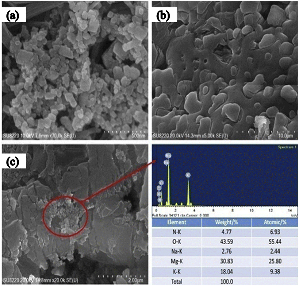 | ||
| Fig. 19 SEM of MgO with solar salt: (a) shows MgO nanoparticles, (b) solar salt, and (c) MgO with solar salt at 5% concentration. Adapted from ref. 35, with permission from Elsevier, Copyright 2020. | ||
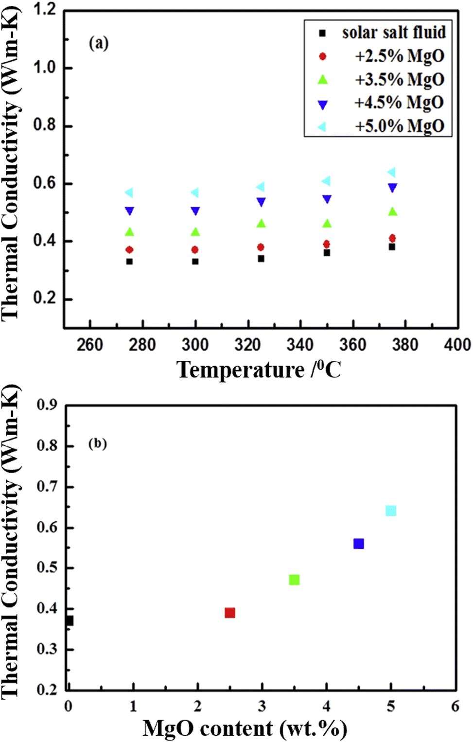 | ||
| Fig. 20 Experimental data showing the thermal conductivity of NaNO3–KNO3 (a) improves with the addition of MgO at different mass concentrations (2.5%, 3.5%, 4.5% and 5%) with temperature, and (b) the increasing thermal conductivity at different concentrations. Adapted from ref. 35, with permission from Elsevier, Copyright 2020. | ||
Besides metal oxides, results using CNTs as an additive in solar salt have been reported. An SEM image is shown in Fig. 21, which shows consistent CNT dispersion in NaNO3–KNO3.39 The authors reported that the solar salt appeared white at room temperature, and after addition of CNTs it became darker. Addition of nanocomposite CNTs39 in solar salt provides good elevation in thermal conductivity, as calculated using the laser flash method with varying mass percentage from 0.1% to 1.5% (Fig. 22). Although some calculations using theoretical models have been done, as discussed, the experimental results are very different due to different BFs, with a large difference in thermal conductivity results.107 However, it is clear that the addition of nanoparticles elevates thermal conductivity and this elevation depends on the quantity of nanoparticles added.
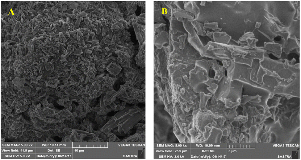 | ||
| Fig. 21 SEM images of pure (A) and CNT-enhanced solar salt, and (B). Adapted from ref. 39, with permission from the American Chemical Society, Copyright 2023. | ||
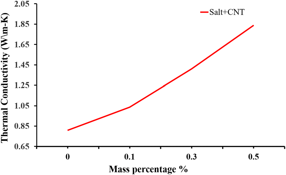 | ||
| Fig. 22 Experimental data showing how the thermal conductivity of NaNO3–KNO3 improves with addition of CNT at different mass concentrations of 0.1%, 0.3% and 0.5%. Adapted from ref. 39, with permission from the American Chemical Society, Copyright 2023. | ||
7 Conclusions and future aspects
An improvement in the thermal conductivity of a solar salt can be observed after the addition of nanoparticles in small amounts, like 2% of CuO by volume increases the thermal conductivity by approximately 30% over the range of temperature, which is a more significant increase than when adding a higher concentration. When using Al2O3 and TiO2 nanoparticles, the elevation in thermal conductivity seen is around 8.3% and 8.1%, respectively.30 However as the mass concentration increases, the changes in thermal conductivity are again not that significance, as also seen in the case of CuO.34 MgO nanoparticles with solar salts show good elevation even at higher concentrations of 5.4% to 62.1%, at 375 °C, but elevate the density of the nanofluid making flow difficult. In the case of CNTs, enhancement in thermal conductivity is around 27% which elevates with mass percentage. CNTs are thermally stable at 600 °C but at higher temperature mass loss rapidly occurs.39Research into latent heat increments in materials for thermal heat storage have included various experimental and theoretical models showing different outcomes and discrepancies.30,107,108 Issues like lack of theoretical understanding and instrumentation errors,91 may be causing the inaccuracy in nanofluid thermal conductivity measurements. Although study results are not always consistent, some conclusions can be drawn, as follows.
• Study of thermal conductivity and the heat transfer capability of the molten salts shows that it can be increased with NP additives.
• Better characterization techniques provide insight into NP additive effects.
• Techniques for the measurement of a nanofluids’ thermophysical properties are still under development.
• Theoretical models and experimental results do not match, which may be due to negligence of various factors.
• Increments in concentration of NPs in the BF leads to agglomeration, which causes uncertainty in the measurements.
• For long durability usage of nanofluids for TES, stability is mandatory for better efficiency and repeatability.
We provide insights into thermal conductivity with respect to theoretical discussion, experimental techniques and mathematics. This will be beneficial in terms of a complete review of variation with temperature or with concentration at a particular temperature, providing the complete results on thermal conductivity enhancement of TES using nanoparticles.
Author contributions
Sanjeev Gautam: conceptualization, investigation, formal analysis, writing – review & editing, resources, funding acquisition, project administration and supervision; Monika Verma: methodology, discussions and original draft preparation; Rashi Chauhan: investigation, formal analysis and revision; Sukesh Aghara: critic discussions and supervision; Navdeep Goyal: critic discussions and supervision.Conflicts of interest
There are no conflicts to declare.Acknowledgements
SG acknowledges the financial support from the CSR-Industrial Research Project from Electrowaves Electronics Pvt. Ltd, Parwanoo, Himachal Pradesh-173 220, India.Notes and references
- J. Bongaarts, Philos. Trans. R. Soc. London, Ser. B, 2009, 364, 2985–2990 CrossRef PubMed.
- H. Ritchie, M. Roser and P. Rosado, Energy, 2022, https://ourworldindata.org/energy.
- T. Stocker, Climate change 2013: the physical science basis: Working Group I contribution to the Fifth assessment report of the Intergovernmental Panel on Climate Change, Cambridge University Press, 2014 Search PubMed.
- Z. Liu, Glob. Energy Interconnect., 2015, 1, 1–64 Search PubMed.
- G. E. Iea, CO2Status Report 2018, IEA, Paris Technical Report, 2019.
- A. Guizani, M. Hammadi, J.-Y. Choley, T. Soriano, M. S. Abbes and M. Haddar, Mech. Ind., 2016, 17, 405 CrossRef.
- IEA, Electricity Market Report, IEA Technical Report, 2021.
- A. Stepanovich, Doctoral thesis, Ruhr-Universität Bochum, Universitätsbibliothek, 2014.
- A. B. Awan, M. Zubair, R. Praveen and A. R. Bhatti, Sol. Energy, 2019, 183, 551–565 CrossRef.
- U. Herrmann and D. W. Kearney, J. Sol. Energy Eng., 2002, 124, 145–152 CrossRef.
- J. F. Kreider, Solar heating design process: active and passive systems, OSTI, 1982 Search PubMed.
- E. B. Kapstein, A Golden Thread: 2500 Years of Solar Architecture and Technology, 1980 Search PubMed.
- L. R. Cirocco, M. Belusko, F. Bruno, J. Boland and P. Pudney, IET Renew. Power Gen., 2015, 9, 379–388 CrossRef.
- S. Manju and N. Sagar, Renewable Sustainable Energy Rev., 2017, 70, 298–313 CrossRef.
- W. Fuqiang, C. Ziming, T. Jianyu, Y. Yuan, S. Yong and L. Linhua, Renewable Sustainable Energy Rev., 2017, 79, 1314–1328 CrossRef.
- A. Ummadisingu and M. Soni, Renewable Sustainable Energy Rev., 2011, 15, 5169–5175 CrossRef.
- A. Kumar, O. Prakash and A. Dube, Renewable Sustainable Energy Rev., 2017, 79, 304–307 CrossRef.
- S. Hasnain, Energy Convers. Manage., 1998, 39, 1127–1138 CrossRef CAS.
- X. Xu, K. Vignarooban, B. Xu, K. Hsu and A. M. Kannan, Renewable Sustainable Energy Rev., 2016, 53, 1106–1131 CrossRef.
- W. Ruidong and M. Jun, IOP Conf. Ser.: Earth Environ. Sci., 2021, vol. 687, p. 012088 Search PubMed.
- J. Len, J. Fernandez and M. Berenguel, et al. , J. Process Control, 2019, 85, 76–90 Search PubMed.
- EASAC, Concentrating solar power plant: its potential contribution to a sustainable energy future, European Academics Science Adisory Council Technical Report, 2011.
- G. Paul, M. Chopkar, I. Manna and P. Das, Renewable Sustainable Energy Rev., 2010, 14, 1913–1924 CrossRef CAS.
- E. González-Roubaud, D. Pérez-Osorio and C. Prieto, Renewable Sustainable Energy Rev., 2017, 80, 133–148 CrossRef.
- K. Vignarooban, X. Xu, A. Arvay, K. Hsu and A. M. Kannan, Appl. Energy, 2015, 146, 383–396 CrossRef CAS.
- A. Gautam and R. Saini, J. Energy Storage, 2022, 48, 103993 CrossRef.
- J. E. Pacheco and R. Gilbert, Overview of recent results of the solar two test and evaluations program, Sandia National Labs., Albuquerque, NM (US) Technical Report, 1999 Search PubMed.
- H. Reilly and G. Kolb, SAND: Sandia National Laboratories, 2001, p. 3674 Search PubMed.
- U. Nithiyanantham, L. González-Fernández, Y. Grosu, A. Zaki, J. M. Igartua and A. Faik, Appl. Therm. Eng., 2020, 169, 114942 CrossRef CAS.
- T. Raja Jeyaseelan, N. Azhagesan and V. Pethurajan, J. Therm. Anal. Calorim., 2019, 136, 235–242 CrossRef.
- S. Ferrouillat, A. Bontemps, O. Poncelet, O. Soriano and J.-A. Gruss, Appl. Therm. Eng., 2013, 51, 839–851 CrossRef CAS.
- J. Singh, G. Kaur and M. Rawat, J. Bioelectron. Nanotechnol., 2016, 1, 1–9 Search PubMed.
- Ç. Oruç and A. Altndal, Ceram. Int., 2017, 43, 10708–10714 CrossRef.
- P. D. Myers Jr, T. E. Alam, R. Kamal, D. Goswami and E. Stefanakos, Appl. Energy, 2016, 165, 225–233 CrossRef.
- X. Wei, Y. Yin, B. Qin, W. Wang, J. Ding and J. Lu, Renewable Energy, 2020, 145, 2435–2444 CrossRef CAS.
- Q. Wang, C. Wu, X. Wang, S. Sun, D. Cui, S. Pan and H. Sheng, Int. J. Heat Mass Transfer, 2023, 205, 123904 CrossRef.
- H. Badenhorst, Sol. Energy, 2019, 192, 35–68 CrossRef CAS.
- B. Jo and D. Banerjee, Int. J. Therm. Sci., 2015, 98, 219–227 CrossRef CAS.
- P. Vigneshwaran, S. Shaik, S. Suresh, M. Abbas, C. A. Saleel and E. Cuce, ACS Omega, 2023, 8(20), 17563–17572 CrossRef CAS PubMed.
- B. Ma and D. Banerjee, AIP Adv., 2017, 7, 115124 CrossRef.
- J. Pearce, Int. J. Med., 2002, 95, 251–252 CAS.
- A.-L. Lavoisier and P. DeLaplace, Obes. Res., 1994, 2, 189–202 CrossRef CAS PubMed.
- J. H. Lambert, Pyrometrie oder vom Maaße des Feuers und der Wärme, bey Haude und Spener, 1779 Search PubMed.
- B. Franklin, Science, 1956, 123, 47–50 CrossRef CAS PubMed.
- J. Ingen-Housz, Nouvelles expériences et observations sur divers objets de physique, Th. Barrois, 1785, vol. 1 Search PubMed.
- C. Rumford, The Collected Works of Count Rumford, Harvard University Press, 1968, vol. 5 Search PubMed.
- J. B. J. Baron Fourier, The analytical theory of heat, The University Press, 1878 Search PubMed.
- T. Narasimhan, arXiv, 2010, preprint, arXiv:1005.2119.
- G.-H. KIm, D. Lee, A. Shanker, L. Shao, M. S. Kwon, D. Gidley, J. Kim and K. P. Pipe, Nat. Mater., 2015, 14, 295–300 CrossRef CAS PubMed.
- K. Wark and D. E. Richards, et al., Termodinámica, McGraw-Hill Madrid, Spain, 2001 Search PubMed.
- R. Serrano-López, J. Fradera and S. Cuesta-López, Chem. Eng. Process., 2013, 73, 87–102 CrossRef.
- D. C. P. Grogan, Development of Molten-Salt Heat Transfer Fluid Technology for Parabolic Trough Solar Power Plants – Public Final Technical Report, Abengoa solar, llc technical report, US Department of Energy, 2013.
- D. Kearney, U. Herrmann, P. Nava, B. Kelly, R. Mahoney, J. Pacheco, R. Cable, N. Potrovitza, D. Blake and H. Price, et al. , J. Sol. Energy. Eng, 2003, 125, 170–176 CrossRef CAS.
- P. K. Das, J. Mol. Liq., 2017, 240, 420–446 CrossRef CAS.
- J. C. Maxwell, Treatise on electricity and magnetism, Hansebooks, 2016 Search PubMed.
- B. Lamas, B. Abreu, A. Fonseca, N. Martins and M. Oliveira, Int. J. Therm. Sci., 2014, 78, 65–76 CrossRef CAS.
- E. J. Wasp, Solid–liquid flow slurry pipeline transportation, Trans. Tech. Publ., 1977 Search PubMed.
- Y. Xuan, Q. Li and W. Hu, AIChE J., 2003, 49, 1038–1043 CrossRef CAS.
- J. Koo and C. Kleinstreuer, J. Nanopart. Res., 2004, 6, 577–588 CrossRef.
- H. Xie, M. Fujii and X. Zhang, Int. J. Heat Mass Transfer, 2005, 48, 2926–2932 CrossRef CAS.
- J. Avsec and M. Oblak, Int. J. Heat Mass Transfer, 2007, 50, 4331–4341 CrossRef CAS.
- S. Pil Jang and S. U. S. Choi, J. Heat Transfer, 2007, 129, 617–623 CrossRef.
- B. C. Pak and Y. I. Cho, Exp. Heat Transfer, 1998, 11, 151–170 CrossRef CAS.
- E. V. Timofeeva, D. S. Smith, W. Yu, D. M. France, D. Singh and J. L. Routbort, Nanotechnology, 2010, 21, 215703 CrossRef PubMed.
- W. Yu and S. Choi, J. Nanopart. Res., 2003, 5, 167–171 CrossRef CAS.
- W. Wei, et al. , J. Adv. Res. Phys., 2017, 3(2), 021209 Search PubMed.
- M. Chandrasekar, S. Suresh, R. Srinivasan and A. C. Bose, J. Nanopart. Nanotechnol., 2009, 9, 533–538 CAS.
- M. Corcione, Energy Convers. Manage., 2011, 52, 789–793 CrossRef CAS.
- I. Gonçalves, R. Souza, G. Coutinho, J. Miranda, A. Moita, J. E. Pereira, A. Moreira and R. Lima, Appl. Sci., 2021, 11, 2525 CrossRef.
- D. W. Hahn and M. N. Özisik, Heat conduction, John Wiley & Sons, 2012 Search PubMed.
- M. L. Ramires, C. A. Nieto de Castro, Y. Nagasaka, A. Nagashima, M. J. Assael and W. A. Wakeham, J. Phys. Chem. Ref. Data, 1995, 24, 1377–1381 CrossRef CAS.
- D. W. G. Ballentyne and D. R. Lovett, A dictionary of Named effects and laws of Chemistry, physics and mathematics, Springer Netherlands, Dordrecht, 1980, pp. 200–217 Search PubMed.
- L. Wei, P. Kuo, R. Thomas, T. Anthony and W. Banholzer, Phys. Rev. Lett., 1993, 70, 3764 CrossRef CAS PubMed.
- T. Ambreen and M.-H. Kim, Appl. Energy, 2020, 264, 114684 CrossRef CAS.
- J. Xu, B. Yu, M. Zou and P. Xu, J. Phys. D: Appl. Phys., 2006, 39, 4486 CrossRef CAS.
- K. Anoop, T. Sundararajan and S. K. Das, Int. J. Heat Mass Transfer, 2009, 52, 2189–2195 CrossRef CAS.
- M. H. Esfe, S. Esfandeh, M. Afrand, M. Rejvani and S. H. Rostamian, Appl. Therm. Eng., 2018, 133, 452–463 CrossRef CAS.
- S. Jana, A. Salehi-Khojin and W.-H. Zhong, Thermochim. Acta, 2007, 462, 45–55 CrossRef CAS.
- S. H. Rostamian, M. Biglari, S. Saedodin and M. H. Esfe, J. Mol. Liq., 2017, 231, 364–369 CrossRef CAS.
- C. H. Chon, K. D. Kihm, S. P. Lee and S. U. Choi, Appl. Phys. Lett., 2005, 87, 153107 CrossRef.
- H. A. Mintsa, G. Roy, C. T. Nguyen and D. Doucet, Int. J. Therm. Sci., 2009, 48, 363–371 CrossRef CAS.
- W. Duangthongsuk and S. Wongwises, Exp. Therm. Fluid Sci., 2009, 33, 706–714 CrossRef CAS.
- C. T. Wamkam, M. K. Opoku, H. Hong and P. Smith, J. Appl. Phys., 2011, 109, 024305 CrossRef.
- B. Wright, D. Thomas, H. Hong, L. Groven, J. Puszynski, E. Duke, X. Ye and S. Jin, Appl. Phys. Lett., 2007, 91, 173116 CrossRef.
- D. Elcock, Potential impacts of nanotechnology on energy transmission applications and needs, Argonne national lab.(anl), argonne, il (united states) technical report, 2007.
- J. Philip and P. D. Shima, Adv. Colloid Interface Sci., 2012, 183, 30–45 CrossRef PubMed.
- A. Asadi, M. Asadi, M. Siahmargoi, T. Asadi and M. G. Andarati, Int. J. Heat Mass Transfer, 2017, 108, 191–198 CrossRef CAS.
- G. Xu, J. Fu, B. Dong, Y. Quan and G. Song, Int. J. Heat Mass Transfer, 2019, 130, 978–988 CrossRef CAS.
- J. Horrocks and E. McLaughlin, Proc. R. Soc. London, Ser. A, 1963, 273, 259–274 Search PubMed.
- H. S. Carslaw and J. C. Jaeger, Conduction of heat in solids, Clarendon Press, Technical Report, 1959 Search PubMed.
- L. Qiu, N. Zhu, Y. Feng, E. E. Michaelides, G. Żyła, D. Jing, X. Zhang, P. M. Norris, C. N. Markides and O. Mahian, Phys. Rep., 2020, 843, 1–81 CrossRef CAS.
- Y. Xuan and Q. Li, Int. J. Heat Fluid Flow, 2000, 21, 58–64 CrossRef CAS.
- J. G. Bleazard and A. S. Teja, J. Chem. Eng. Data, 1995, 40, 732–737 CrossRef CAS.
- A. A. Guermoudi, P. Y. Cresson, A. Ouldabbes, G. Boussatour and T. Lasri, J. Therm. Anal. Calorim., 2021, 145, 1–12 CrossRef CAS.
- D. G. Cahill, Rev. Sci. Instrum., 1990, 61, 802–808 CrossRef CAS.
- P. Bhattacharya, S. Nara, P. Vijayan, T. Tang, W. Lai, P. Phelan, R. Prasher, D. Song and J. Wang, Int. J. Heat Mass Transfer, 2006, 49, 2950–2956 CrossRef.
- S. K. Das, N. Putra, P. Thiesen and W. Roetzel, J. Heat Transfer, 2003, 125, 567–574 CrossRef CAS.
- B. Lin, H. Ban, C. Li, R. N. Scripa, C.-H. Su and S. L. Lehoczky, ASME International Mechanical Engineering Congress and Exposition, 2005, pp. 725–730 Search PubMed.
- X. Wang, X. Xu and S. U. Choi, J. Thermophys. Heat Transfer, 1999, 13, 474–480 CrossRef CAS.
- T. T. Loong and H. Salleh, IOP Conf. Ser.: Mater. Sci. Eng., 2017, vol. 226, p. 012146 Search PubMed.
- H. Kurt and M. Kayfeci, Appl. Energy, 2009, 86, 2244–2248 CrossRef CAS.
- R. Powell, J. Sci. Instrum., 1957, 34, 485 CrossRef.
- A. A. Rousan and D. M. Roy, Ind. Eng. Chem. Prod. Res. Dev., 1983, 22, 349–351 CrossRef CAS.
- S. Ganguly and S. Chakraborty, Phys. Lett. A, 2011, 375, 2394–2399 CrossRef CAS.
- S. Lee, S.-S. Choi, S. Li and J. Eastman, J. Heat Transfer, 1999, 121(2), 280–289 CrossRef CAS.
- J. Magnusson, M. Memmott and T. Munro, Ann. Nucl. Energy, 2020, 146, 107608 CrossRef CAS.
- S. M. Mamand, Appl. Sci., 2021, 11, 1459 CrossRef CAS.
- D. Ceotto and V. Y. Rudyak, Colloid J., 2016, 78, 509–514 CrossRef CAS.
| This journal is © The Royal Society of Chemistry 2023 |