
 Open Access Article
 This Open Access Article is licensed under a
 Creative Commons Attribution 3.0 Unported Licence
Optimising the synthesis of LiNiO2: coprecipitation versus solid-state, and the effect of molybdenum doping†
Jaime-Marie
Price
 *ab,
Phoebe
Allan
*ab and
Peter
Slater
*ab
*ab,
Phoebe
Allan
*ab and
Peter
Slater
*ab
aSchool of Chemistry, University of Birmingham, Birmingham, B15 2TT, UK. E-mail: p.r.slater@bham.ac.uk; jxp407@student.bham.ac.uk; p.allan@bham.ac.uk
bThe Faraday Institution, Harwell Science and Innovation Campus, Didcot, OX11 0RA, UK
First published on 4th May 2023
Abstract
LiNiO2 (LNO) was prepared by two synthesis techniques: solid-state (SS-LNO) and coprecipitation (C-LNO). The results showed that C-LNO could be synthesised in as little as 1 hour at 800 °C in O2 to give a pristine material. The layered oxide structures of both materials have been investigated using PXRD, confirming that phase pure samples have been made. Electrochemical properties were explored over a range of voltage windows (2.7–4.1 V, 2.7–4.2 V and 2.7–4.3 V vs. Li+/Li), to analyse how the H2–H3 phase transition impacts the cathode materials’ capacity retention. Electrochemical measurements showed that the initial discharge capacity and cycle stability are improved in C-LNO compared to SS-LNO, achieving 221 mA h g−1 and 199 mA h g−1 respectively in the voltage range 2.7–4.3 V (at 10 mA g−1), with capacity retentions of 47% and 41% after 100 cycles. A Mo doped system, Li1.03Mo0.02Ni0.95O2 (Mo-LNO) was then prepared via the solid-state route. Mo-LNO showed an even higher initial discharge capacity of 240 mA h g−1 between 2.7–4.3 V vs. Li+/Li, with a slightly enhanced capacity retention of 52%. Through the investigation of the different voltage ranges it was shown that capacity fade can be minimised by cycling the materials below 4.2 V, (attributed to avoiding the detrimental H2–H3 phase transition) although this results in a lower discharge capacity. This is shown by the cycling of SS-LNO, C-LNO and Mo-LNO in the voltage window 2.7–4.1 V, where discharge capacities of 144 mA h g−1, 168 mA h g−1 and 177 mA h g−1 were achieved with higher capacity retentions of 84%, 76% and 90% after 100 cycles respectively, the latter system showing promise as a cobalt-free cathode material.
Introduction
As countries commit to reducing green-house gas emissions, emphasis on developing more sustainable modes of transport has led to a large increase in the use of electric vehicles (EVs). As of 2022, 17 countries have committed to totally phase out internal combustion engine vehicles or to develop 100% zero-emission transportation by 2050.1 With this in mind, extensive research has been employed into the development and manufacture of rechargeable Li-ion batteries (LiBs), which are crucial to delivering high voltage, high energy density and long cycle life for EV applications.2 Given that the battery and particularly the cathode material is the most expensive component of an EV, significant attention is focused on developing high-performance cathode materials that can deliver lower cost, improved safety and longer driving times between charges.1First commercialised in 1991 by Sony, LiCoO2 is a layered oxide cathode material with a hexagonal structure, analogous to α-NaFeO2.3,4 It is an O3 type structure, meaning that lithium ions occupy octahedral sites with three CoO2 layers per unit cell.5 Oxygens stack in an ABCABC arrangement along the c-axis, giving rise to the hexagonal lattice (space group R![[3 with combining macron]](https://www.rsc.org/images/entities/char_0033_0304.gif) m).6,7 This structure allows lithium to move easily in and out of the material between the CoO2 layers.8 This was originally the cathode material of choice as it has a high operating voltage (∼3.6 V vs. Li+/Li) and a theoretical capacity of ∼274 mA h g−1, albeit the usable capacity is significantly lower at around 150 mA h g−1. However, cobalt is expensive at $52
m).6,7 This structure allows lithium to move easily in and out of the material between the CoO2 layers.8 This was originally the cathode material of choice as it has a high operating voltage (∼3.6 V vs. Li+/Li) and a theoretical capacity of ∼274 mA h g−1, albeit the usable capacity is significantly lower at around 150 mA h g−1. However, cobalt is expensive at $52![[thin space (1/6-em)]](https://www.rsc.org/images/entities/char_2009.gif) 000 per ton,9 and unevenly distributed globally. There are also serious ethical concerns over the mining of cobalt, including stories of forced child labour, a lack of personal protective equipment for workers and forced evictions for mining projects.10 This has shifted the research focus to other layered transition metal oxide cathode materials where the Co content is reduced, including LiMO2 (M = Ni, Mn), Li [Ni1−x−yCoxMny]O2 (NMC) and Li[Ni1−x−yCoxAly]O2 (NCA).11–15
000 per ton,9 and unevenly distributed globally. There are also serious ethical concerns over the mining of cobalt, including stories of forced child labour, a lack of personal protective equipment for workers and forced evictions for mining projects.10 This has shifted the research focus to other layered transition metal oxide cathode materials where the Co content is reduced, including LiMO2 (M = Ni, Mn), Li [Ni1−x−yCoxMny]O2 (NMC) and Li[Ni1−x−yCoxAly]O2 (NCA).11–15
With the idea of driving down costs, LNO has been explored as a potential cathode material since the late 1990s. In September 2022, the price of Ni was $22000 per ton, significantly cheaper than Co, with it also being more abundant.9,16 LNO is isostructural to LiCoO2 and so it was only logical to investigate its electrochemical properties. Although it was shown to have a high experimental capacity of around 200 mA h g−1, this material itself faces some drawbacks and so shifted out of focus for many years. These drawbacks include being inherently difficult to synthesise stoichiometrically, predominantly down to cation mixing between Li+/Ni2+, due to similarities in the ionic size of Li+ and Ni2+. As a result of this, antisite defects occur (Li and Ni exchange sites within the layers).17 LNO also commonly contains an excess of Ni2+ in the Li layers due to lithium loss occurring through the long synthesis times and because of the incomplete oxidation of Ni2+ to Ni3+. These issues correlate to rapid capacity fade being observed, which leads to poor cycling stability. These deficiencies have led to LNO currently not being used in mass applications, although Mn and Co doped analogues (NMCs) are widely used.
To overcome the synthetic challenges of LNO, various synthesis techniques have been employed in the literature including solid-state reactions (SS), coprecipitation methods and hydrothermal processes, however, details of the optimisation of these synthetic processes have not previously been reported. The hydrothermal process is regarded as an inherently complicated process and is difficult to scale up and so is not studied here.18 This work therefore focuses on optimising the synthesis of LNO via two methods-solid-state and coprecipitation. Synthesis conditions including reaction time, temperature, and Li-excess level were optimised to synthesise stoichiometric LNO with minimal numbers of antisite defects. It is shown herein that the coprecipitation route has the advantage of synthesising phase pure LNO in a 1 hour sintering step, saving energy, time, and money. The work is then extended to prepare a new Mo-doped LNO material via SS, where we show a promising performance.
During cycling, LNO undergoes multiple phase transitions enabled by the electrostatic interactions from the ionic bonds that stabilize its structure. On delithiation, LNO is observed to transition through a series of phases; hexagonal (H1) → monoclinic (M) → second hexagonal (H2) → third hexagonal (H3), all of which possess an O3 sequence, with a symmetry reduction from Rm to C2/m for the monoclinic phase.19–23 On charging LixNiO2, the material undergoes a solid-solution reaction until x = 0.75, when the material undergoes its first phase transition from H1 → M. The M phase then remains stable until x = 0.4 to 0.36, when the phase changes again from M → H2. Finally, at 4.2 V (vs. Li+/Li), where the lithium content ranges from x = 0.26–0.16, a transition from H2 → H3 occurs, with the c-lattice parameter of the H3 phase being considerably smaller. Currently in the literature, there is debate around what state of charge (SoC) these transitions occur at, however, the discrepancies observed could be a result of different cycling conditions, cell fabrication and also the amount of cation mixing occurring within materials.19,21 Nevertheless, it is agreed in the literature that when LNO cells are cycled at 4.2 V or above (vs. Li+/Li), rapid capacity fade is seen. This coincides with the H2 → H3 transition and the drastic changes in the c-lattice parameter.19,23,24 As expected, this strains the LNO particles, leading to cracking and stacking faults in primary particles, thus reducing the stability of the material. In particular, cracks can lead to the cathode material becoming permanently electronically disconnected from the bulk, decreasing the capacity the material can achieve. Cracks also lead to fresh cathode material being exposed to electrolyte, allowing further side reactions to occur.19,20,23 Therefore, in this work we have also investigated the effect of limiting the upper cut-off voltage to 4.1 V, 4.2 V and 4.3 V (vs. Li+/Li) during electrochemical cycling. This is to evaluate how the H2–H3 transition affects the capacity fade of the materials made here and to determine whether high capacities can be achieved without severe capacity fade.
We also investigated the possibility of doping LNO to improve the performance. Mo was chosen as a dopant for a few reasons; it has been shown in the literature to enhance the electrochemical performance of NMC type materials, and Mo has a high charge and so allows extra Li introduction into the structure for charge balance.25–32 Research conducted by Park et al. indicated that Mo may have a ‘pillaring effect’ in Ni-rich NMC type materials.33 This is achieved by doping Mo into the layered oxide structure, where Mo occupies Ni sites. On high levels of delithiation, it is thought the Mo ions then act as pillars to hold the TM layers apart, thereby reducing the effect of the H2–H3 phase transition, as the difference between the H2 and H3 c-lattice parameter is no longer as great, allowing for the re-intercalation of the Li ions more easily back into the layered oxide structure. This then in turn reduces the capacity fade seen in the material. Other groups have also reported that low level doping with Mo in NMC materials can enhance the capacity and electrochemical stability.25–30,32 Sun et al. indicated that 1% Mo6+ doping in TM layers of Ni-rich Li[Ni0.91Co0.09]O2 led to an increased capacity retention with in situ XRD measurements showing smaller volume and c-lattice parameter changes during charging and discharging, compared to their pristine material. This is thought to be down to the stabilisation of the micro and atomic structure via pillaring effects.34 Yet to the best of our knowledge, there are limited reports on the effect of Mo-doping on pristine LNO. In this research, low level doping Mo was therefore employed via solid-state synthesis to try and overcome the capacity fade seen in LNO and diminish some of the effects of the H2–H3 phase transition. The results of Mo doping indicated a 20% improvement in discharge capacity as well as improved cycling stability. This is discussed later in the paper.
Experimental
Solid-state synthesis
LiNiO2 (SS-LNO) and Li1.03Mo0.02Ni0.95O2 (Mo-LNO) were synthesised by hand grinding together stoichiometric amounts of precursors Li2CO3 (Alfa Aesar, 99%) and Ni(NO3)2·6H2O (Alfa Aesar, 99.99%) and MoO3 (Sigma Aldrich, 99.99%). These were then heated in air at 650 °C for 12 hours with a ramp rate of 2.5 °C min−1 in a furnace in a fumehood. The resultant powders were then ball milled (Fritsch, Planetary Micro Mill Pulverisette 7 Classic Line) for 30 minutes at 500 rpm in ∼2 mL hexane, using zirconia mill pots and 10 mm ZrO2 balls. Powders were dried and heated a second time for 12 hours using different atmospheres and/or temperatures: between 700–900 °C with a ramping rate of 5 °C min−1 under a constant flow of oxygen or between 900–950 °C with a ramping rate of 5 °C min−1 in air.Coprecipitation synthesis
LiNiO2 (C-LNO) was also prepared using a coprecipitation route. Ni(OH)2 precursor particles were synthesised by precipitation from an aqueous solution of Ni(NO3)2·6H2O. Ni(NO3)2·6H2O was first dissolved in 100 mL of water and stirred on the hotplate at 80 °C for 1 hour. 2 M NaOH (aq) was then added until pH 11 was reached. The pale green precipitate of Ni(OH)2 was filtered, washed and dried at 100 °C overnight. The Ni(OH)2 precursor was then ground with stoichiometric amounts of LiOH·H2O and heated between 700–800 °C with a ramp rate of 5 °C min−1 under a constant flow of oxygen for 1–12 hours to obtain LNO.X-ray diffraction
For identification of crystalline phases, powder samples were analysed using a Bruker D8 X-ray diffractometer (Cu Kα radiation source, λ = 1.5418). Diffraction patterns were collected in the 2θ range of 15–70° at 0.02° steps for 0.5 seconds per step. Rietveld refinement was employed using the General Structure Analysis System II (GSAS-II) programme to determine the cell parameters. Li/Ni site mixing was also refined. This was done by making Li and Ni atom positions equivalent and then refining their respective fractions in each of these atomic positions.Electrochemistry
Cathode slurries were made by mixing N-methyl-2-pyrrolidone (NMP) with a powder containing active material (AM), carbon black (C-65), graphite and polyvinylidene difluoride (PVDF) in the ratio 80:10:5:5 respectively. The slurry was mixed using a Thinky mixer (Intertronics, Thinky ARE-250) at 2000 rpm. This was then coated onto an Al foil current collector to a thickness of 100 microns using a doctor blade. It was allowed to dry on a hotplate in a fume hood at 80 °C for 1 hour to allow the NMP to evaporate. The coating was then transferred to a vacuum oven and allowed to dry overnight at 110 °C.
The cathode coating was then used to construct LIR2032 coin cells. These contained around 3–5 mg of active material cut into 14.8 mm discs. CF/C glass fibre separator was used with Li-metal as a counter electrode, cut into 16 mm and 15 mm discs respectively. 80 μL 1M LiPF6 in 1:1 ethylene carbonate:dimethyl carbonate (EC:DMC) with 2 wt% of vinyl chloride was used as the electrolyte. The coin cells were assembled in a dry room (temperature controlled at 20 °C, with an average dew point of −50 °C Td). The cycling performance of the cathode materials was analysed in the voltage window 2.7–4.3 V (vs. Li+/Li) at 25 °C (Biologic BCS-COM cell tester used, operated by BT-Lab software). For cells tested over the different voltage ranges 2.7–4.1 V, 2.7–4.2 V and 2.7–4.3 V, the current density was kept constant at 10 mA g−1 for 100 cycles to allow the stability of the materials at different cut-off voltages to be examined. To test the rate capability of the materials (between 2.7–4.3 V vs. Li+/Li) the current density was changed every 5 cycles (10 mA g−1, 20 mA g−1, 30 mA g−1, 40 mA g−1, 50 mA g−1, 10 mA g−1). These cell tests were all done in triplicate.
Results and discussions
Initially, the optimised synthetic conditions for the synthesis of LNO via solid-state synthesis and coprecipitation were investigated.Solid-state synthesis
As a baseline sample, LNO was prepared by solid-state synthesis. For solid-state synthesis, all materials were heated to 650 °C in air, ball milled and then reheated a second time between 700–950 °C for 12 hours in different atmospheres. PXRD patterns provide a lot of detail about the quality of the LNO sample synthesised. It is widely acknowledged in the literature that the intensity ratio of I(003)/I(104) gives a good indication of the order within the lattice system, with a ratio value of 1.2 or above showing a well-ordered lattice with minimal antisite defects.4,24,35,36 Splitting between (006) and (102) as well as (108) and (110) also indicate the order within the lattice and minimal cation mixing.32,37–39 Other key reflections include the (101) and (006)/(102) reflections at 36° and 38° 2θ, which give an indication of the cation mixing within the sample. Samples with fewer antisite defects from cation mixing will exhibit PXRD patterns where the (101) reflection is more intense than the (006)/(102).24,35,40 These characteristics can be used as an early indication that the LNO made has a good layered structure and will give a good electrochemical performance.35 Structural data for SS LNO samples are tabulated in Table 1.| Sample | Synthesis conditions | c (Å) | a (Å) | Volume (Å3) | I (003)/I(004) | R w |
|---|---|---|---|---|---|---|
| SS-LNO | 700 °C/12 h in O2 | 14.1948(5) | 2.8782(1) | 101.84(1) | 1.66 | 4.1 |
| SS-LNO | 900 °C/12 h in O2 | 14.2151(7) | 2.8878(3) | 102.66(1) | 1.19 | 5.0 |
| SS-LNO | 650 °C/12 h in O2 | 14.1800(8) | 2.8853(2) | 102.23(6) | 1.15 | 4.8 |
Prior literature suggests at least 12 hours of heating is needed to form LNO via SS methods.19,22,41 Therefore, SS-LNO was first synthesised at 950 °C in air with no excess lithium for 12 hours respectively (Fig. 1). However, analysis of the PXRD pattern gave an I(003)/I(104) ratio of 1.15 (less than the accepted 1.2 for a well ordered lattice) and no clear splitting between the (006)/(102) and (108)/(110) peaks is observed. Site occupancy factors from Rietveld refinement of the LNO structure against PXRD data indicated that more than 7% cation mixing was present (ESI,† Table S2). Previous reports in the literature indicated that the best conditions to synthesise near-stoichiometric LNO was under a constant flow of oxygen and with a small amount of lithium excess.4,20,24,40 A constant flow of O2 hinders the reduction of Ni3+ to Ni2+, which in turn lowers the number of antisite defects and cation mixing. The lithium excess is used to counteract the volatility of Li at higher temperatures, as such Li loss can again give a suboptimal material.4,24,35,42 LNO synthesised in oxygen flow using 5% excess lithium at a slightly lower temperature of 900 °C (Fig. 1) for 12 hours displayed an I(003)/I(104) ratio of 1.19, which was still indicative of Li/Ni site mixing. Li/Ni site mixing was minimised by heating the sample to 700 °C for 12 hours under a flow of oxygen, using 5% excess lithium to counteract the lithium volatility during the long duration heat treatment. The I(003)/I(104) ratio achieved was 1.66 with clear peak splitting observed between (006)/(102) and (108)/(110) and the (101) reflection is more intense than the (006)/(102) reflections, indicating that cation mixing is minimal. The Mo-doped LNO material was also synthesised using these optimised solid-state conditions (XRD shown in the ESI,† Fig. S1).
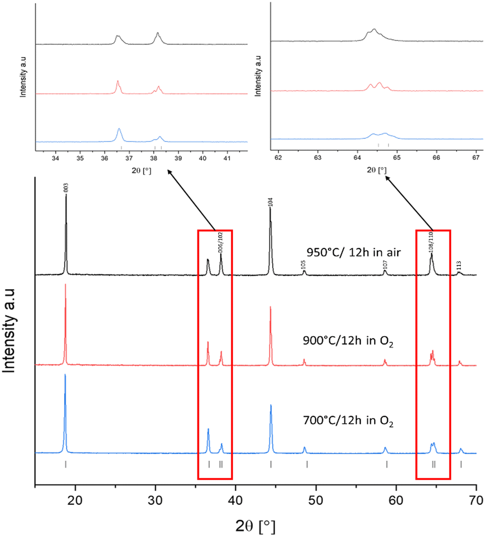 | ||
| Fig. 1 XRD patterns for SS-LNO synthesised at different temperatures and different atmospheres. Caption for each pattern outlines: sintering temperature, sintering time and atmosphere used. Boxed regions shown zoomed images of peak splitting. | ||
Coprecipitation synthesis
In a bid to try to reduce synthesis times, LNO has also been synthesised via an initial coprecipitation route. This method has only one heating stage compared to two for the SS method. It is also thought to give more homogenous mixing of reagents to generate materials with higher reactivity.43 This process involves the synthesis of a Ni(OH)2 precursor, followed by a grinding step with LiOH·H2O and then finally heating to between 700–800 °C in O2. As a starting point, C-LNO was synthesised at 700 °C for 12 hours under a flow of oxygen with varying lithium excess from no excess to 10% excess (Fig. S2, ESI†). The resultant XRD pattern showed an unoptimized synthesis, showing materials with a layered oxide structure but with impurities present such as Li2CO3 and NiO. With these impurities in mind, and to try and reduce sintering times further, a range of synthesis tests were performed (Tabulated in the ESI,† Table S3). Ultimately, LNO was synthesised via coprecipitation by heating to 800 °C for 1 hour only in O2. Between 0–5% excess lithium was explored, with no excess proving the optimised synthesis conditions to form phase pure LNO (Fig. S3, ESI†). In this respect, it is interesting to note that Li et al., have commented on how long sintering times and temperatures 700 °C and above leads to Li loss from the lattice and Ni reduction, exacerbating the effects of cation off-stoichiometry and mixing.17 This Li loss then leads to Ni and Li leaving the lattice and migrating to the surface of the material where it forms impurity phases such as NiO, Li2CO3 and LiOH when exposed to O2, CO2 and H2O in the air.17,20,24,40 Thus, we have shown here that these effects are somewhat diminished due to the very short heating time used, and no Li excess was needed to form this phase pure C-LNO.Comparison of samples synthesised by solid-state and coprecipitation routes
Fig. 2 shows the XRD patterns for the optimised materials made via solid-state and coprecipitation, both with a layered oxide structure (Rm space group), with refined parameters shown in the ESI† (Fig. S4 and S5). Cell parameters for each of these samples are shown in Table 2. The I(003)/I(104) ratio for C-LNO and SS-LNO are 2.12 and 1.66 respectively, showing the materials made via the optimised synthesis have a good layered order with minimal antisite defects. C-LNO has not only the highest I(003)/I(104) ratio, but also good peak splitting between (006) and (102) as well as (108) and (110) reflections, indicating that this material has a lesser degree of cation mixing compared to the other materials synthesised.2,44,45
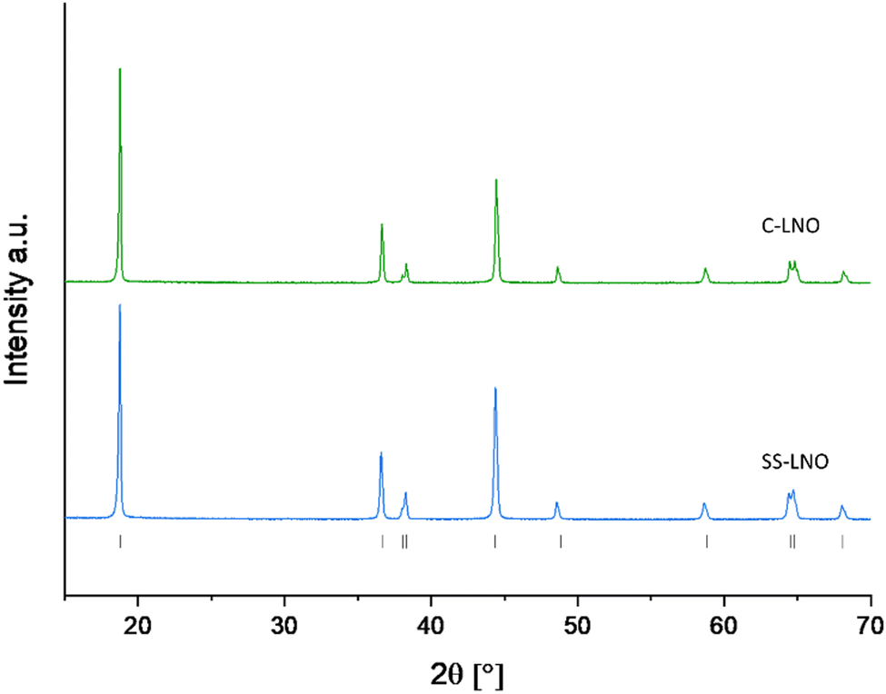 | ||
| Fig. 2 XRD pattern of SS-LNO synthesised at 700 °C for 12 hours in O2 (blue), and C-LNO synthesised at 800 °C for 1 hour in O2 (green). | ||
| Sample | c (Å) | a (Å) | c/a | Volume (Å3) | Li (3b) | Ni (3b) | I (003)/I(104) |
|---|---|---|---|---|---|---|---|
| SS-LNO | 14.1948(5) | 2.8782(1) | 4.932 | 101.84(1) | 0.98(1) | 0.02(1) | 1.66 |
| C-LNO | 14.2021(4) | 2.8795(3) | 4.932 | 101.98(1) | 0.99(1) | 0.01(1) | 2.12 |
To try and improve the capacity fade and maintain a high capacity of LNO, the material was doped with low levels of MoO3 to form Li1.03Mo0.02Ni0.95O2 (denoted Mo-LNO herein). Due to the fact that it was not possible to make a Mo doped Ni(OH)2 precursor (since Mo6+ precipitates under acidic rather than basic conditions), this material was prepared by the solid-state route under the same conditions used for LNO (for XRD and refinement see Fig. S1 and S6 in ESI†). The Li content was increased, and the Ni content reduced to charge balance the introduction of the higher charge of Mo.
Electrochemical testing – solid-state LNO
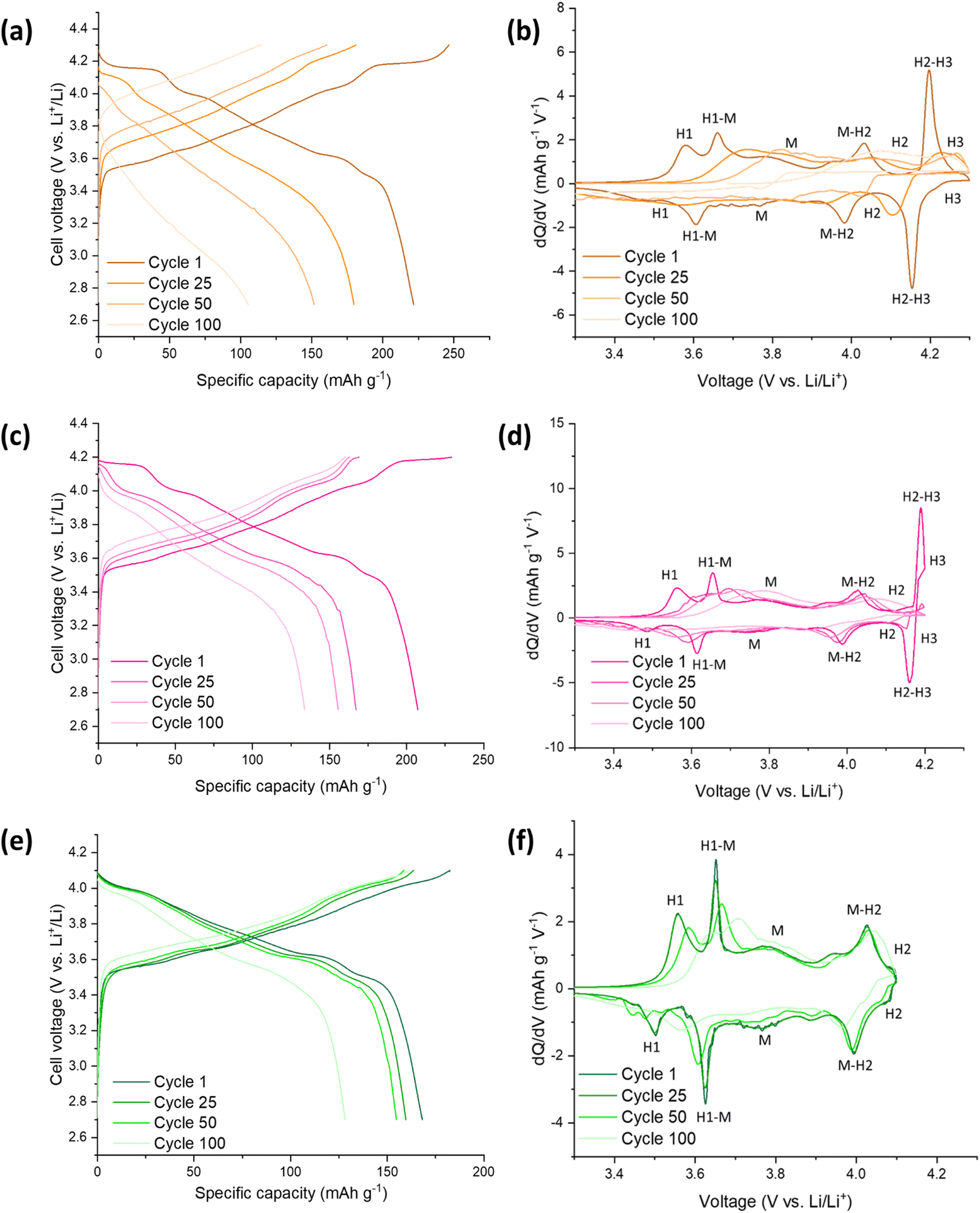
The electrochemical performance of the SS-LNO material was evaluated by galvanostatic cycling in a LIR2032 coin cell. The half-cells were cycled between voltage limits of 2.7–4.3 V against Li metal. The SS LNO cells shown in Fig. 3 were cycled at a current density of 10 mA g−1 for 100 cycles with cut-off voltages of 4.1 V, 4.2 V and 4.3 V (Fig. 3(a), 3(c) and 3(e) respectively). SS LNO had an initial discharge capacity of 199.1 mA h g−1, 181.8 mA h g−1 and 143.8 mA h g−1 at cut-off 4.3 V, 4.2 V and 4.1 V respectively. Thus, as expected, decreasing the cut-off voltage lowers the capacity that the material can achieve.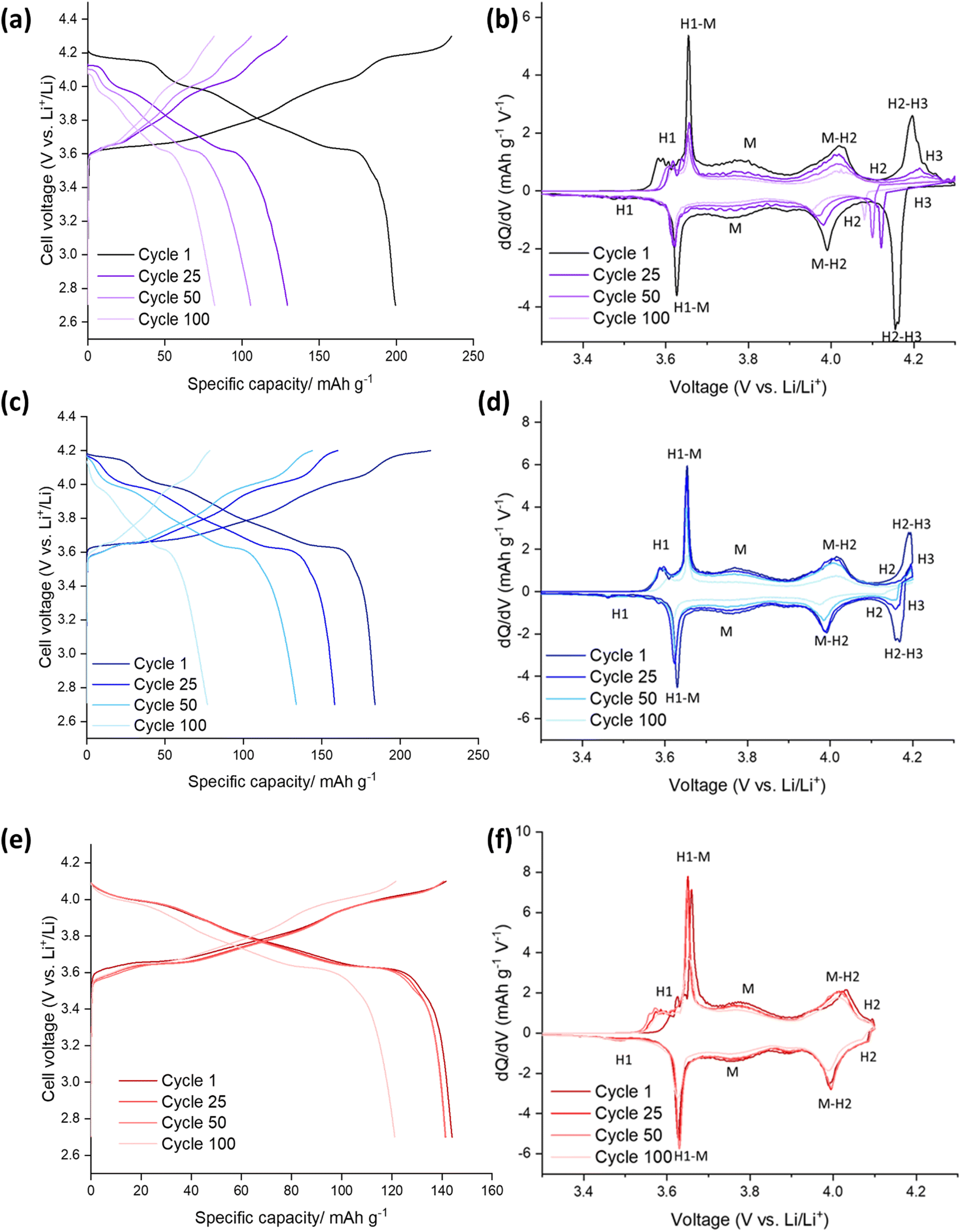 | ||
| Fig. 3 Electrochemical performance during galvanostatic charge and discharge of SS-LNO/Li half cells at 10 mA g−1: (a) between 2.7–4.3 V (b) corresponding differential capacity (dQ/dV) plot with phases (c) between 2.7–4.2 V (d) corresponding differential capacity (dQ/dV) plot with phases (e) between 2.7–4.1 V (f) corresponding differential capacity (dQ/dV) plot with phases. | ||
After 100 cycles, the discharge capacities are 82.2 mA h g−1 (cut-off 4.3 V), 77.0 mA h g−1 (cut-off 4.2 V) and 121.2 mA h g−1 (cut-off 4.1 V), giving capacity retentions of 41%, 42% and 84% respectively. This shows that the lower cut-off voltage of 4.1 V leads to slower capacity fade in the material and significantly, a higher capacity after 100 cycles than for higher cut off voltages. From the differential capacity plots shown in Fig. 3 (dQ/dV vs. V), above 4.1 V the plots in Fig. 3(d) and (e) show a well-defined peak which has been assigned to the H2–H3 phase transition, with the H3 phase transitions occurring at 4.2 V. The dQ/dV plots and the discharge capacities reported here match well with previous literature.22,23,46 This H2–H3 transition leads to the abrupt shrinkage of the c-lattice parameter, as highlighted in the introduction.19–21,23,24 This translates to severe strain across the material, facilitating electrode pulverisation and leading to the observed large irreversible capacity loss. This can be seen in dQ/dV plots in Fig. 3(b) and (d) by the lowering of peak intensities and the slight shift in peaks as the cells are cycled up to 100 times. Cycling to the lower cut off voltage of 4.1 V means that the H2–H3 phase transition does not occur, and so only 16% of the initial capacity was lost after 100 cycles (with peak intensities also remaining consistent in the dQ/dV plot), emphasising that it is the H2–H3 transition that is mainly responsible for the detrimental performance loss of the material.
Electrochemical testing – coprecipitation LNO
Fig. 5 highlights the voltage profiles for C-LNO at voltages 2.7–4.3 V, 2.7–4.2 V and 2.7–4.1 V and their corresponding differential capacity plots. C-LNO had initial discharge capacities of 221.4 mA h g−1, 207.1 mA h g−1 and 168.0 mA h g−1 at cut-offs of 4.3 V, 4.2 V and 4.1 V respectively. This is on average 14% higher than the SS-LNO material, showing that the material synthesised via coprecipitation at 800 °C for 1 hour has a higher capacity than the material synthesised via solid-state at 700 °C for 12 hours. It is important to note that in the C-LNO material, the redox activity starts at 3.5 V (vs. Li+/Li), compared to at 3.6 V (vs. Li+/Li) for SS-LNO. This could be one factor as to why a higher capacity is seen for C-LNO as the material is redox active over a slightly higher voltage range. However, after 100 cycles significant capacity fade is still seen at all the cut-off voltages. The cells cycled to 4.3 V, 4.2 V and 4.1 V had discharge capacities of 103.4 mA h g−1, 133.8 mA h g−1 and 128.2 mA h g−1 after 100 cycles, giving a capacity retention of 47%, 65% and 76% respectively. The capacity retentions at cut off voltages 4.3 V and 4.1 V are comparable for the SS-LNO and C-LNO after 100 cycles. However, interestingly the capacity retention at cut-off voltage 4.2 V is significantly higher (65% vs. 42%) in the C-LNO material when compared to the SS-LNO. One explanation for this could be because C-LNO has less cation mixing and antisite defects than SS-LNO (3b site occupancies tabulated in Table 2). This may improve the inherent stability of the material and lead to less losses on prolonged cycling of the material.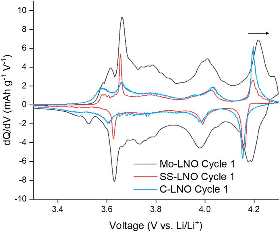 | ||
| Fig. 4 Comparison of first cycle differential capacity (dQ/dV) plots for Mo-LNO (black), SS-LNO (red) and C-LNO (blue) in the voltage window 2.7–4.3 V. This shows a shift to a higher voltage for the H2–H3 phase transition in Mo-LNO. | ||
 | ||
| Fig. 5 Electrochemical performance during galvanostatic charge and discharge of C-LNO/Li half cells at 10 mA g−1: (a) between 2.7–4.3 V (b) corresponding differential capacity (dQ/dV) plot with phases (c) between 2.7–4.2 V (d) corresponding differential capacity (dQ/dV) plot with phases (e) between 2.7–4.1 V (f) corresponding differential capacity (dQ/dV) plot with phases. | ||
Electrochemical testing – SS Mo-LNO
The Mo-LNO was electrochemically tested using the same conditions as the SS-LNO and C-LNO materials to make all the data directly comparable. Fig. 6 shows the voltage profiles and corresponding differential capacity plots for Mo-LNO tested between voltage limits 2.7–4.1 V, 2.7–4.2 V and 2.7–4.3 V, with Fig. 7 showing the cycling stability over 100 cycles and rate tests for the respective voltage ranges.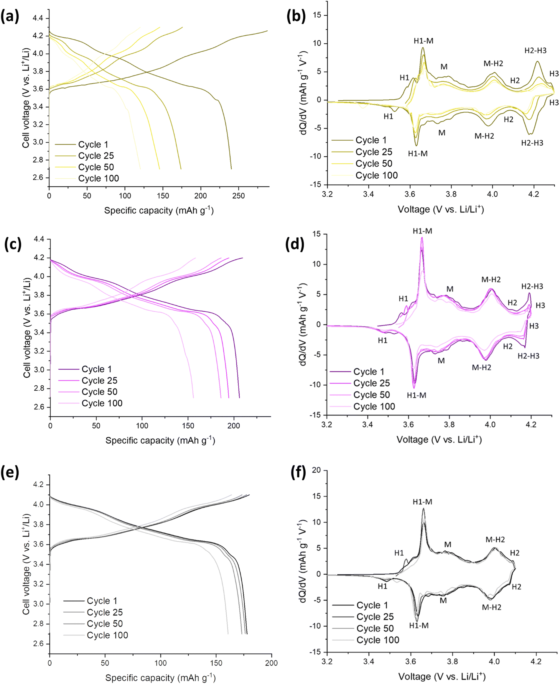 | ||
| Fig. 6 Electrochemical performance during galvanostatic charge and discharge of Mo-LNO/Li half cells at 10 mA g−1: (a) between 2.7–4.3 V (b) corresponding differential capacity (dQ/dV) plot with phases (c) between 2.7–4.2 V (d) corresponding differential capacity (dQ/dV) plot with phases (e) between 2.7–4.1 V (f) corresponding differential capacity (dQ/dV) plot with phases. | ||
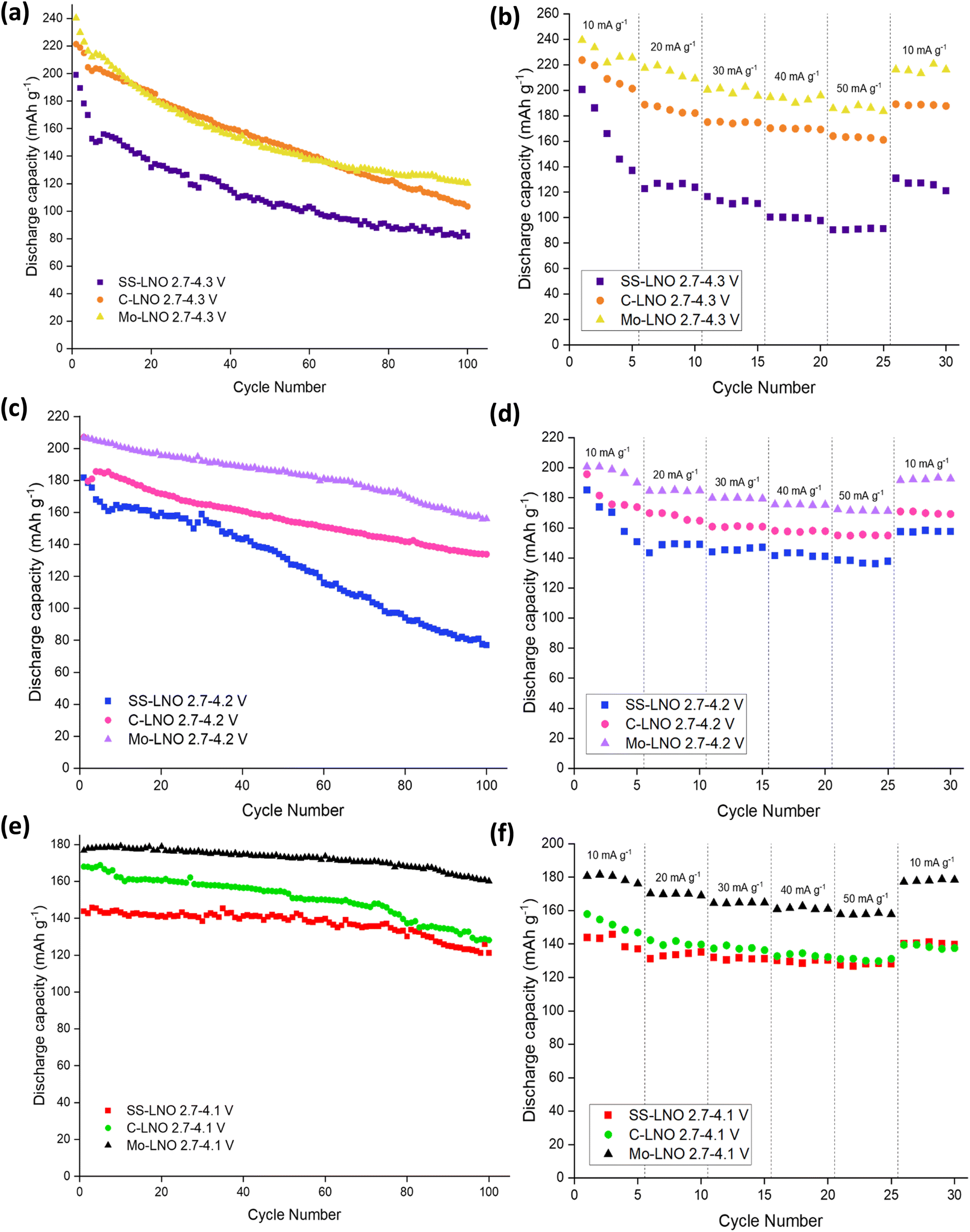 | ||
| Fig. 7 Comparison of SS-LNO, C-LNO and Mo-LNO over 100 cycles at (a) 2.7–4.3 V, (c) 2.7–4.2 V and (e) 2.7–4.1 V. Rate tests also shown between (b) 2.7–4.3 V, (d) 2.7–4.2 V and (f) 2.7–4.1 V for SS-LNO, C-LNO and Mo-LNO. | ||
The highest initial capacity for any of the materials discussed in this paper was achieved for this Mo-LNO phase in the voltage window 2.7–4.3 V (vs. Li+/Li). This gave a value of 240 mA h g−1, compared to 221.4 mA h g−1 and 199.1 mA h g−1 for C-LNO and SS-LNO in the same voltage window (Fig. 3(a) and 5(a) respectively). The Mo-LNO also had a higher initial capacity in the 2.7–4.2 V and 2.7–4.1 V voltage windows, being 207 mA h g−1 and 177 mA h g−1 respectively (Fig. 6(c) and (e)). After the Mo-LNO had completed 100 cycles, the discharge capacity dropped to 120 mA h g−1, 156 mA h g−1 and 160 mA h g−1 for cut off voltages 4.3 V, 4.2 V and 4.1 V respectively. This corresponds to a capacity retention of 50% (4.3 V), 75% (4.2 V) and 90% (4.1 V). From the dQ/dV plots in Fig. 6(b) and (d), at cut-off voltages of 4.3 V and 4.2 V, the H2–H3 phase transition is still present in this Mo-LNO material. However, the capacity fade seen in Mo-LNO is less than in the corresponding SS-LNO and C-LNO at all the cut-off voltages. Nevertheless, it should also be noted that the peaks for the H2–H3 phase transition in Fig. 6(b) and (d) are slightly broader compared to the dQ/dV plots for C-LNO and SS-LNO under the same electrochemical conditions (Fig. 5(b), 5(d) and 3(b) and 3(d) respectively), while the high voltage “plateau” starts to slope more. This may give an early indication that the Mo could be having some pillaring type effect within the layered oxide Mo-LNO material to reduce the large volume change effect of the H2–H3 phase transition (as the H2–H3 transition is still occurring) and stabilising the structure, which in turn helps to reduce the capacity fade seen within the material.
From Fig. 4, making a direct comparison of the dQ/dV plots for the Mo-LNO and LNO samples also shows significantly that the H2–H3 transition is shifted to a slightly higher voltage, which is consistent with more Li being removed before the transition occurs, and therefore allowing for a greater Li removal and hence higher capacity.
The results here thus agree with previous research where Mo doping has been utilised for Ni-rich NMC cathode materials, and the improved performance attributed to this pillaring effect allowing facile movement of Li+ between these layers during charge and discharge.25–34
In terms of the significantly improved overall capacity on Mo doping, this can be attributed to several factors: the introduction of Mo6+ in place of Ni3+ requires further charge balance by the introduction of extra Li+ in place of Ni3+ leading to a Li rich phase where Li:Ni ratio >1, increasing the theoretical capacity of the material. The consequence of this will be also likely to help suppress detrimental Li/Ni antisite defects. Therefore, the increased Li content, reduction in Li/Ni antisite defects, Mo pillaring effect and influence of the shifted H2–H3 transition, all allowing for more Li removal, can most likely account for the significantly improved performance.
During the course of this paper being under review, similar beneficial results for Mo doping were reported by Li et al.47 In this work, the authors examined higher Mo contents, Li1+yNi(3−5y)/3Mo2y/3O2 0.03 ≤ y ≤ 0.12) with samples prepared by a sol gel-type route. This work suggested the coexistence of a Mo doped Li rich LiNiO2 phase and Li4MoO5 with the former refined as Li1.04Ni0.93Mo0.03O2, which is close to the composition reported here, which we observed as the Mo doping limit before a rock salt impurity was observed (ESI†-Fig. S15). Interestingly this work by Li et al., showed that the presence of Li4MoO4 appears to help to reduce capacity fade by providing an”epitaxial stabilization” effect for the Li rich LNO domain. It is therefore possible that some of the improved capacity retention in our systems compared to undoped LNO may relate to a small amount of local Li4MoO4 domains, although the retention we observe (for the comparable 4.3 V cut off) is lower than observed for the higher Mo contents studied by Li et al., therefore suggesting that any Li4MoO4 levels are significantly lower. Also, given the observed changes in peak ratios I(003)/I(104) (reported in Table S1, ESI†) and the shift to a higher voltage of the H2–H3 transition, we believe that the evidence points to most of the Mo being incorporated into the LNO phase in our material.
Long term cycling and rate testing of SS LNO, C-LNO and SS Mo-LNO
A comparison of SS-LNO, C-LNO and Mo-LNO at different cut off voltages over 100 cycles and during rate tests is shown in Fig. 7. These materials were also electrochemically tested between 2.7–4.3 V, 2.7–4.2 V and 2.7–4.1 V at different current densities. The capacity retention at these different current densities is shown in Fig. 7(b), 7(d) and 7(f) respectively. For SS-LNO, at 2.7–4.3 V (vs. Li+/Li), the discharge capacity drops rapidly over the first 5 cycles from 200 mA h g−1 to 137 mA h g−1 at a current density of 10 mA g−1.Here the H2–H3 phase transition is occurring, showing the detrimental effect this has on the capacity the material can achieve. When the current density was increased to 50 mA g−1, a capacity of 91 mA h g−1 was achieved – 45.5% of the initial capacity, representing a substantial drop in performance. A similar effect is seen for rate tests performed between 2.7–4.2 V for SS-LNO, shown in Fig. 7(d). Again, the H2–H3 transition occurs in these cells. In this case, 26% of the initial capacity was lost in the first 5 cycles (from 185 mA h g−1 to 137 mA h g−1). However, the capacity was more stable at higher rates, still maintaining 137 mA h g−1 at a current density of 50 mA g−1. When the current density returned to 10 mA g−1, the capacity returned to 157 mA h g−1, giving a capacity retention of 85% at a cut off voltage of 4.2 V. The rate performance tests were shown to be most stable for SS-LNO between 2.7–4.1 V, where the H2–H3 phase transition is not occurring. Although the initial capacity was lowest in this voltage range at 144 mA h g−1, after the first 5 cycles the capacity was still 137 mA h g−1, giving a capacity retention of 95%. At 50 mA g−1, a capacity of 128 mA h g−1 was achieved (88% of initial capacity) and then when the current density was returned to 10 mA g−1, the capacity increased to 141 mA h g−1, indicating a capacity retention of 98%. These rate tests further confirm that it is the occurrence of the H2–H3 transition in SS-LNO that detrimentally affects the rate capability and capacity retention of the LNO cathode material.
As with SS-LNO, C-LNO was also electrochemically tested at multiple current densities between voltage limits of 2.7–4.1 V, 2.7–4.2 V and 2.7–4.3 V (vs. Li+/Li) to evaluate the effect the synthesis technique and the cut-off voltage had on the rate capability of the material. This is also shown in Fig. 7. The initial discharge capacity between 2.7–4.3 V for C-LNO was 224 mA h g−1, dropping to 201 mA h g−1 after 5 cycles giving a capacity loss of 11% (Fig. 7(b)). This is lower than the capacity lost for SS-LNO over the first 5 cycles in the sample voltage range, which lost 31.5% of its original capacity. When C-LNO was cycled at a current density of 50 mA g−1 between 2.7–4.3 V, a discharge capacity of 163 mA h g−1 was achieved. On returning the current density to 10 mA h g−1, a discharge capacity of 189 mA h g−1 was retained, corresponding to 84% of the initial discharge capacity. This was a higher capacity retention of 84% for C-LNO compared to 65% for SS-LNO under the same testing conditions, with C-LNO also having a higher discharge capacity, once more illustrating the better capacity performance of the coprecipitation material. Similar effects are seen for C-LNO tested between 2.7–4.2 V and 2.7–4.1 V, as shown in Fig. 7(d) and 7(f) respectively. The C-LNO sample tested between 2.7–4.2 V achieved an initial discharge capacity of 196 mA h g−1, decreasing to 173 mA h g−1 after the first 5 cycles. However, SS-LNO only achieved 185 mA h g−1 decreasing to 137 mA h g−1 under the same conditions. For C-LNO, the capacity appears to be more stable at higher rates when the cut off voltage is limited to 4.2 V compared to 4.3 V, giving a discharge capacity of 155 mA h g−1 at 50 mA g−1 (79% of initial capacity). When returning the current density to 10 mA g−1, 87% of the original discharge capacity was achieved. Although the initial discharge capacity is lowest for C-LNO when the voltage is set between 2.7–4.1 V, the material is most stable when performing rate tests within these voltage limits, as the H2–H3 phase transition is not occurring in this voltage range. From Fig. 7(f) you can see an initial discharge capacity of 158 mA h g−1 is achieved, decreasing by 7% in the first 5 cycles. At 50 mA g−1, a discharge capacity of 131 mA h g−1 is seen and when the current density is returned to 10 mA g−1, the capacity increases back to 139 mA h g−1 giving 88% capacity retention. As for the other voltage ranges, C-LNO shows a higher capacity of 158 mA h g−1 compared to 144 mA h g−1 for SS-LNO when comparing rate testing between 2.7–4.1 V. Overall, these results indicate that although the H2–H3 phase transition is occurring in C-LNO tested at cut-off voltages 4.2 V and 4.3 V, the effects are not as severe as in SS-LNO, which is evident in the reduced capacity fade. The higher capacities and the reduction in capacity fade seen in C-LNO can be attributed to the more optimised synthesis of C-LNO. Thus, synthesising C-LNO at 800 °C for 1 hour only in O2 yields a higher quality material with less cation mixing (Table 2) and a more perfectly ordered layered oxide, which can be supported by the higher capacities seen for the C-LNO material.
Fig. 7 also shows the rate tests performed on the Mo-LNO material within the voltage windows of 2.7–4.3 V, 2.7–4.2 V and 2.7–4.1 V. As shown for the undoped LNO materials, the voltage window 2.7–4.1 V proved to be the most stable during cycling at varied rates, due to the H2–H3 phase transition not occurring here (Fig. 7(f)). An initial discharge capacity of 181 mA h g−1 was achieved, losing only 2% of this initial capacity in the first 5 cycles. At 50 mA g−1, the material had a discharge capacity of 158 mA h g−1, giving 81% capacity retention. When the current density was returned to 10 mA g−1, the Mo-LNO showed a capacity of 178 mA h g−1, meaning 98% of the overall capacity was retained. This is not only a higher capacity achieved compared to SS-LNO and C-LNO, but also a better capacity retention. For Mo-LNO tested between 2.7–4.2 V, an initial discharge capacity of 200 mA h g−1 was seen, decreasing to 190 mA h g−1 in the first 5 cycles. At 50 mA g−1, 172 mA h g−1 was achieved and when the rate was returned to 10 mA g−1, the capacity also increased back to 192 mA h g−1, giving an overall capacity retention of 96%. In the voltage window 2.7–4.3 V, an initial capacity of 240 mA h g−1 was observed, reducing by 6% on the first 5 cycles and further reducing to 188 mA h g−1 at a rate of 50 mA g−1. When the rate was returned to 10 mA g−1, a capacity of 216 mA h g−1 was achieved, giving a 90% capacity retention.
Overall, the data in Fig. 7 shows that the Mo-LNO material proved to be more stable with a higher capacity and less capacity fade than the SS-LNO and C-LNO during rate testing and long-term cycling, suggesting that the detrimental effect of the H2–H3 phase transition is slightly suppressed by the incorporation of small amounts of Mo into the LNO material. It is also evident that low level Mo doping enhances the discharge capacity seen in LNO, possibly relating to the corresponding increase in Li content for charge balance, the small shift in the voltage for the H2–H3 phase transition and a pillaring effect by Mo.
Conclusions
This work has investigated optimising the synthesis of LNO via solid-state and coprecipitation, as well as exploring the effects of varying the cut-off voltage on electrochemical performance. It has shown that via a coprecipitation route LNO can be synthesised in as little as 1 hour at 800 °C under a flow of oxygen. This is the shortest time reported so far for this material. PXRD data suggests that this C-LNO is more crystalline and has a better layered order with less cation mixing than SS-LNO synthesised for 12 hours at 700 °C. Electrochemical data also reveal a higher discharge capacity for C-LNO, although substantial capacity fade is seen in all materials above 4.2 V due to the occurrence of the H2–H3 phase transition. Mo doping was then investigated and was shown to not only increase the capacity, but also reduce the effect of the H2–H3 phase transition, decreasing the capacity fade seen. Particularly, in the lower voltage window 2.7–4.1 V, this material gave a high capacity of 177 mA h g−1 along with a respectable retention of 90% after 100 cycles. Further work is needed to investigate the synthesis of this Mo doped phase via a coprecipitation route to further optimise performance, as well as the study of larger Mo contents, which have the potential to offer improved stability due to a stabilising effect from Li4MoO4 domains.47 In this respect, the preparation of this phase by this route is more challenging, due to the fact that the Ni2+ precipitates in alkaline conditions, while the Mo6+ only precipitates in acidic conditions.Overall, this work highlights that LNO can be prepared in very short heat treatment times, and that low level Mo doping can have a significant effect on improving the cathode materials performance. These finding can be employed to form new Ni-rich doped materials (e.g. co-doping with Mo and other transition metals) to propel us ever closer to optimising this phase to reach the demands needed to satisfy the expanding EV industry.
Data availability
All data associated with this paper are openly available from: https://doi.org/10.25500/edata.bham.00000934.Author contributions
Jaime-Marie Price: methodology, investigation, formal analysis, and writing – original draft. Peter R. Slater: conceptualization, methodology, supervision, resources, and writing – review and editing. Phoebe K. Allan: conceptualization, supervision, resources, and writing – review and editing.Conflicts of interest
There are no conflicts to declare.Acknowledgements
This research has been supported by the Faraday Institution CATMAT project (FIRG016), ReLiB (FIRG005 and FIRG006) and nextrode (FIRG015) projects. The authors would like to thank Daniel Butler, Bo Dong, Rosie Madge and Abbey Jarvis for their continued support during the months this lab work and research was conducted.Notes and references
- IEA, Global EV Outlook 2020, https://www.iea.org/reports/global-ev-outlook-2020, (accessed 29 October 2020).
- S. Cui, Y. Wei, T. Liu, W. Deng, Z. Hu, Y. Su, H. Li, M. Li, H. Guo, Y. Duan, W. Wang, M. Rao, J. Zheng, X. Wang and F. Pan, Adv. Energy Mater., 2016, 6, 1501309 CrossRef.
- J. W. Fergus, J. Power Sources, 2010, 195, 939–954 CrossRef CAS.
- T. Ohzuku, A. Ueda and M. Nagayama, J. Electrochem. Soc., 1993, 140, 1862–1870 CrossRef CAS.
- T. A. Arunkumar, E. Alvarez and A. Manthiram, J. Mater. Chem., 2008, 18, 190–198 RSC.
- J. Bai, W. Sun, J. Zhao, D. Wang, P. Xiao, J. Y. P. Ko, A. Huq, G. Ceder and F. Wang, Chem. Mater., 2020, 32, 9906–9913 CrossRef CAS.
- N. Mohamed and N. K. Allam, RSC Adv., 2020, 10, 21662–21685 RSC.
- K. Momma and F. Izumi, J. Appl. Crystallogr., 2011, 1272–1276 CrossRef CAS.
- The London Metal Exchange – an HKEX Company, LME Cobalt, https://www.lme.com/en-GB/Metals/Minor-metals/Cobalt#tabIndex=2, (accessed 13 April 2021).
- Amnesty International, Amnesty International Report, 2020.
- J. Cheng, L. Mu, C. Wang, Z. Yang, H. L. Xin, F. Lin and K. A. Persson, J. Mater. Chem. A, 2020, 8, 23293–23303 RSC.
- S. T. Myung, F. Maglia, K. J. Park, C. S. Yoon, P. Lamp, S. J. Kim and Y. K. Sun, ACS Energy Lett., 2017, 2, 196–223 CrossRef CAS.
- D. Andre, S. J. Kim, P. Lamp, S. F. Lux, F. Maglia, O. Paschos and B. Stiaszny, J. Mater. Chem. A, 2015, 3, 6709–6732 RSC.
- H. H. Ryu, G. T. Park, C. S. Yoon and Y. K. Sun, J. Mater. Chem. A, 2019, 7, 18580–18588 RSC.
- M. M. Thackeray, S. H. Kang, C. S. Johnson, J. T. Vaughey, R. Benedek and S. A. Hackney, J. Mater. Chem., 2007, 17, 3112–3125 RSC.
- The London Metal Exchange – an HKEX Company, LME Nickel, https://www.lme.com/en-GB/Metals/Non-ferrous/Nickel#tabIndex=2, (accessed 13 April 2021).
- H. Li, W. Hua, M. Etter, S. Mangold, G. Melinte, N. Pietro, M. Casati, H. Ehrenberg and S. Indris, Chem. Mater., 2022, 34, 8163–8177 CrossRef CAS.
- K. Heo, J. Lee, Y.-W. Song, M.-Y. Kim, H. Jeong, A. DoCheon, K. Jaekook and J. Lim, J. Electrochem. Soc., 2021, 168, 010521 CrossRef CAS.
- C. Xu, P. J. Reeves, Q. Jacquet and C. P. Grey, Adv. Energy Mater., 2021, 11, 1–12 Search PubMed.
- M. Bianchini, M. Roca-Ayats, P. Hartmann, T. Brezesinski and J. Janek, Angew. Chem., Int. Ed., 2019, 58, 10434–10458 CrossRef CAS PubMed.
- L. de Biasi, A. Schiele, M. Roca-Ayats, G. Garcia, T. Brezesinski, P. Hartmann and J. Janek, ChemSusChem, 2019, 12, 2240–2250 CrossRef CAS PubMed.
- W. Li, J. N. Reimers and J. R. Dahn, Solid State Ionics, 1993, 67, 123–130 CrossRef CAS.
- C. S. Yoon, D. W. Jun, S. T. Myung and Y. K. Sun, ACS Energy Lett., 2017, 2, 1150–1155 CrossRef CAS.
- P. Kalyani and N. Kalaiselvi, Sci. Technol. Adv. Mater., 2005, 6, 689–703 CrossRef CAS.
- O. Breuer, A. Chakraborty, J. Liu, T. Kravchuk, L. Burstein, J. Grinblat, Y. Kauffman, A. Gladkih, P. Nayak, M. Tsubery, A. I. Frenkel, M. Talianker, D. T. Major, B. Markovsky and D. Aurbach, ACS Appl. Mater. Interfaces, 2018, 10, 29608–29621 CrossRef CAS PubMed.
- Y. Feng, C. Li, S. Li and L. Ai, IOP Conf. Ser. Earth Environ. Sci., 2018, 153, 1–6 Search PubMed.
- Y. Su, Y. Yang, L. Chen, Y. Lu, L. Bao, G. Chen, Z. Yang, Q. Zhang, J. Wang, R. Chen, S. Chen and F. Wu, Electrochim. Acta, 2018, 292, 217–226 CrossRef CAS.
- F. A. Susai, D. Kovacheva, A. Chakraborty, T. Kravchuk, R. Ravikumar, M. Talianker, J. Grinblat, L. Burstein, Y. Kauffmann, D. T. Major, B. Markovsky and D. Aurbach, ACS Appl. Energy Mater., 2019, 2, 4521–4534 CrossRef CAS.
- Y. Zang, C. X. Ding, X. C. Wang, Z. Y. Wen and C. H. Chen, Electrochim. Acta, 2015, 168, 234–239 CrossRef CAS.
- X. Yuan, Q. J. Xu, X. Liu, W. Shen, H. Liu and Y. Xia, Electrochim. Acta, 2016, 207, 120–129 CrossRef CAS.
- H. Konishi, M. Yoshikawa and T. Hirano, J. Power Sources, 2013, 244, 23–28 CrossRef CAS.
- Y. Zhang, Z. B. Wang, F. Da Yu, L. F. Que, M. J. Wang, Y. F. Xia, Y. Xue and J. Wu, J. Power Sources, 2017, 358, 1–12 CrossRef CAS.
- G. T. Park, B. Namkoong, S. Bin Kim, J. Liu, C. S. Yoon and Y. K. Sun, Nat. Energy, 2022, 7, 946–954 CrossRef CAS.
- H. H. Sun, U. H. Kim, J. H. Park, S. W. Park, D. H. Seo, A. Heller, C. B. Mullins, C. S. Yoon and Y. K. Sun, Nat. Commun., 2021, 12, 1–11 CrossRef PubMed.
- Y. Sun, P. Wan, J. Pan, C. Xu and X. Liu, Solid State Ionics, 2006, 177, 1173–1177 CrossRef CAS.
- H. Das, A. Urban, W. Huang and G. Ceder, Chem. Mater., 2017, 29, 7840–7851 CrossRef CAS.
- G. Li, Z. Zhang, R. Wang, Z. Huang, Z. Zuo and H. Zhou, Electrochim. Acta, 2016, 212, 399–407 CrossRef CAS.
- X. Bie, F. Du, Y. Wang, K. Zhu, H. Ehrenberg, K. Nikolowski, C. Wang, G. Chen and Y. Wei, Electrochim. Acta, 2013, 97, 357–363 CrossRef CAS.
- A. Sharma, A. Rajkamal, S. Kobi, B. S. Kumar, A. K. Paidi, A. Chatterjee and A. Mukhopadhyay, ACS Appl. Mater. Interfaces, 2021, 13, 25836–25849 CrossRef CAS PubMed.
- J. Xu, E. Hu, D. Nordlund, A. Mehta, S. N. Ehrlich, X. Q. Yang and W. Tong, ACS Appl. Mater. Interfaces, 2016, 8, 31677–31683 CrossRef CAS PubMed.
- H. Li, N. Zhang, J. Li and J. R. Dahn, J. Electrochem. Soc., 2018, 165, A2985–A2993 CrossRef CAS.
- R. Moshtev, P. Zlatilova, V. Manev and K. Tagawa, J. Power Sources, 1996, 62, 59–66 CrossRef CAS.
- Y. K. Sun, D. J. Lee, Y. J. Lee, Z. Chen and S. T. Myung, ACS Appl. Mater. Interfaces, 2013, 5, 11434–11440 CrossRef CAS PubMed.
- J. P. Peres, C. Delmas, A. Rougier, M. Broussely, F. Perton, P. Biensan and P. Willmann, J. Phys. Chem. Solids, 1996, 57, 1057–1060 CrossRef CAS.
- H. Arai, S. Okada, H. Ohtsuka, M. Ichimura and J. Yamaki, Solid State Ionics, 1995, 80, 261–269 CrossRef CAS.
- J. Barker, R. Koksbang and M. Y. Saidi, Solid State Ionics, 1996, 2738, 25–35 CrossRef.
- B. Li, G. Rousse, L. Zhang, M. Avdeev, M. Deschamps, A. M. Abakumov and J. M. Tarascon, Energy Environ. Sci., 2023, 2, 1210–1222 RSC.
Footnote |
| † Electronic supplementary information (ESI) available. See DOI: https://doi.org/10.1039/d3ya00046j |
| This journal is © The Royal Society of Chemistry 2023 |