
 Open Access Article
 This Open Access Article is licensed under a Creative Commons Attribution-Non Commercial 3.0 Unported Licence
Enhancing low electronic conductivity materials in all active material electrodes through multicomponent architecture†
Chen
Cai
and
Gary M.
Koenig
Jr.
 *
*
Department of Chemical Engineering, University of Virginia, 102 Engineers Way, Charlottesville, VA 22904-4741, USA. E-mail: gary.koenig@virginia.edu; Fax: +1-434-982-2658; Tel: +1-434-982-2714
First published on 13th January 2023
Abstract
Lithium-ion batteries are used in many applications due to their high volumetric and gravimetric energy density. One general route to increase cell level battery energy density is to use thick electrodes, although as electrode thickness increases electronic and ionic microstructure transport limitations must be given more consideration. One system that enables the development and study of very thick electrodes is “All Active Material” (AAM) electrodes, which are comprised of only electroactive material which has been mechanically compressed and mildly thermally treated to result in a porous electrode pellet. In this manuscript, the incorporation of a material with relatively high gravimetric capacity but low electronic conductivity into an AAM cathode will be described. The material, LiNi0.5Mn0.5O2 (LNMO), when used in isolation has very high polarization as an AAM electrode which is attributed to the low electronic conductivity in the electrode microstructure. A second material with higher electronic conductivity but lower gravimetric capacity, LiCoO2 (LCO), was combined with the LNMO to form a multicomponent AAM cathode. The LCO/LNMO blends displayed improvements in electrochemical battery properties attributed to the LCO forming a percolated network for electron conduction while the LCO and LNMO particles/phases still remained segregated in the electrode architecture. The electrochemical outcomes were further analyzed in the context of pseudo-two-dimensional simulations of cycling the cells. This study establishes a new concept in incorporating relatively low electronic conductivity materials into AAM electrodes by taking advantage of a multicomponent architecture.
1. Introduction
Secondary lithium-ion batteries (LIBs) have been the prevailing energy storage technology for electric vehicles and portable electronics.1–5 Towards achieving higher energy density in LIBs, researchers have pursued increasing areal and volumetric energy within electrodes.6–13 One general route to increase areal energy/capacity/loading is to increase the electrode thickness. However, with thicker electrodes, the rate limiting process shifts from resistances due to solid-state diffusion and/or the electroactive interface and towards ionic transport through the microstructure, which includes both depletion of accessible Li+ concentrations in the electrolyte and increased ionic resistance due to long transport path lengths.6–14 When conventional composite electrodes are used, the ion transport is even more restrictive due to inactive binder and conductive additives in the interstitial regions of the electrode, resulting in high tortuosity. Conventional composite electrode tortuosity has been reported with values up to 9, with corresponding Bruggeman exponents up to 4.5; compared to exponents of 1 for perfectly aligned pores and 1.5 often assumed for packed spheres.15–18 One electrode design free of polymer and carbon additives is All Active Material (AAM) electrodes (also called “sintered electrode” in our previous works), where the electroactive material particles are hydraulically pressed and mildly thermally treated to form a porous pellet.8–13,19 Although the dimensions of AAM electrodes in many reports do not change with thermal treatment and structural changes such as necking are generally not observed, the heating process is still necessary for mechanical stability of the porous pellets. AAM electrodes usually have thicknesses over a half millimeter and areal loadings exceeding 200 mg cm−2.20 Such electrode microstructures not only reduce tortuosity, but due to large thickness decrease the relative fraction of inactive but necessary cell components such as current collectors and separators.8,11,13,16In the absence of conductive additives, electronic transport through the matrix for AAM electrodes must proceed solely through the electroactive material. LiCoO2 (LCO), with relatively high electronic conductivity (upon ∼3% delithiation over 1 S m−1),15,21 thus has been used as an AAM cathode in multiple studies.11–13 However, LCO has drawbacks of environmental concerns and relatively high cost, and also the gravimetric capacity is lower than many other layered metal oxide cathode materials.22,23 Alternative layered oxide cathode materials with higher capacity often substitute Co with lower cost Ni and Mn, however, electronic conductivities of these materials are intrinsically much lower than LCO.24–30
Inspired by the framework of conventional composite electrodes where conductive carbon additives form a percolated network to facilitate efficient electronic conduction through the electrode matrix, it was hypothesized that LCO could serve a similar role of providing the necessary electronic conductivity to enable the use of Co-free cathode materials. These materials otherwise have limited capacity in AAM electrodes at reasonable rates of charge/discharge due to low electronic conductivity. An illustrative cartoon of the concept of the LCO phase facilitating electronic conduction through the electrode matrix can be found in Fig. 1. In this work, blended AAM cathodes with different ratios of LCO and a Co-free layered cathode material LiNi0.5Mn0.5O2 (LNMO) were prepared. LNMO was chosen as an exemplar material because it is Co-free, has relatively low electronic conductivity to make the impact of the blending with LCO more pronounced,31,32 and has the same Li stoichiometry and layered structure as LCO and thus deleterious interface formation during thermal processing was expected to be less likely.19,30,33
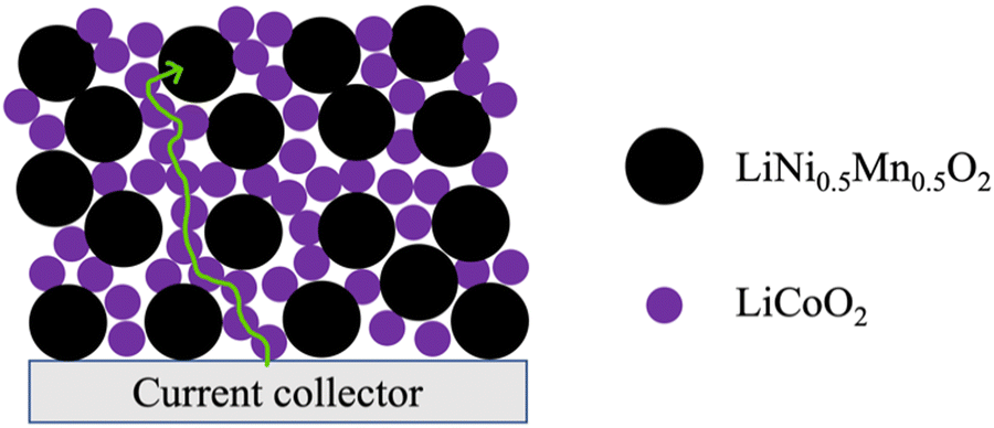 | ||
| Fig. 1 Cartoon illustrating the LiCoO2 (LCO) network in a multicomponent AAM electrode facilitating electronic conductivity through the electrode matrix. Larger black dots and smaller purple dots represent the LiNi0.5Mn0.5O2 (LNMO) and LCO particles, respectively. The green line depicts a relatively low resistance electronic conduction path from the current collector to a LNMO particle far from the current collector via the LCO network in the AAM electrode. | ||
2. Methods & materials
2.1 Active material powder synthesis
LNMO was synthesized via high temperature lithiation and calcination of a transition metal oxalate precursor.34–36 The precursor was synthesized using precipitation methods. 200 mM of sodium oxalate (Na2C2O4) was dissolved into 400 mL of deionized (DI) water within a 1000 mL beaker. 100 mM of manganese sulfate monohydrate (MnC2O4·2H2O, Fisher Chemical) and 100 mM of nickel sulfate hexahydrate (NiSO4·6H2O, Fisher Chemical) were dissolved into 400 mL DI water using a separate 1000 mL beaker. Both solutions were heated to 60 °C before pouring the Mn/Ni sulfate solution into the oxalate solution all at once. The precipitation reaction proceeded for 30 minutes at 60 °C at 300 RPM stirring. Then, the precipitate was collected using vacuum filtration and rinsed with 1.6 L DI water before drying overnight at 80 °C in air. The resulting Ni0.5Mn0.5C2O4·2H2O was mixed with LiOH with a target molar ratio of 1![[thin space (1/6-em)]](https://www.rsc.org/images/entities/char_2009.gif) :1.1 transition metal:Li using mortar and pestle by hand for 10 minutes. The powder mixture was then transferred to a furnace (Carbolite CWF 1300) for calcination. The temperature profile for the thermal process included a hold at 480 °C for 3 hours and then 950 °C for 10 hours in air. Temperature increases occurred at a rate of 1 °C min−1, but the cooling rate back to room temperature was not controlled.
:1.1 transition metal:Li using mortar and pestle by hand for 10 minutes. The powder mixture was then transferred to a furnace (Carbolite CWF 1300) for calcination. The temperature profile for the thermal process included a hold at 480 °C for 3 hours and then 950 °C for 10 hours in air. Temperature increases occurred at a rate of 1 °C min−1, but the cooling rate back to room temperature was not controlled.
For LCO, 200 mM each of Na2C2O4 and cobalt sulfate heptahydrate (CoSO4·7H2O, Acros Organics) were separately dissolved into 400 mL of DI water in two 1000 mL beakers. The reaction conditions were otherwise the same as the LNMO precursor synthesis. The CoC2O4·2H2O was mixed with Li2CO3 (Fisher Chemical) with a target molar ratio of 2:1.05 oxalate precursor:lithium carbonate. The mixture was heated to 800 °C without a hold at the top temperature using a heating rate of 1 °C min−1. Upon reaching the set temperature, cooling proceeded to room temperature without temperature control. The synthesized powder was then ball-milled (Fritsch Pulverisette 7 planetary ball miller) with zirconia beads of 4.8 mm diameter for 5 hours at 300 RPM using a powder to beads mass ratio of 1:5.
2.2 AAM electrode fabrication
To fabricate AAM electrode cathodes, the synthesized active material powders of LNMO and LCO were used in isolation or in blends. For AAM anodes, the material was purchased from a commercial vendor and was Li4Ti5O12 (LTO, NEI corporation). Material and electrochemical properties for the LCO and LTO materials, both in conventional composite and AAM electrodes, have been reported previously.8,11,12 To prepare an AAM electrode, 1 g of active material powder was blended with 2 mL of 1 wt% polyvinyl butyral (PVB, Pfaltz & Bauer) in ethanol. The suspension was mixed using mortar and pestle by hand until the ethanol evaporated and the powder appeared dry. PVB-coated powder was used for fabricating all the AAM electrodes.For AAM cathodes used in battery full cells, PVB-coated LNMO and LCO powder were used and blended at the desired mass ratio by hand using mortar and pestle. The compositions used on a LCO mass percentage basis were 0%, 15%, 30%, 45%, 60%, and 100% (denoted as 0%LCO, 15%LCO, 30%LCO, 45%LCO, 60%LCO, and 100%LCO). 0.2 g of resulting cathode powder was loaded into a pellet die (Carver) with diameter of 13 mm before being hydraulically pressed at 430 MPa for 2 minutes (Carver). The pressed pellet was thermally treated by heating to 600 °C at a rate of 1 °C min−1 without a hold and then allowed to cool without control over the cooling rate to room temperature in air. 600 °C was chosen to according to previous studies, as below this temperature the pellets often have lower mechanical stability which impacts processing into functional cells.8,30 The AAM cathode pellets had thicknesses ranging from 450 to 550 μm as measured using callipers and loadings ranging from 145 to 150 mg cm−2. Due to the morphology and particle size differences, the pellet geometric void/pore volume fraction for pure LNMO was 0.41 and approximately linearly decreased to 0.33 for pure LCO (see Fig. S1, ESI†). No noticeable shrinkage or expansion was observed before and after the mild sintering for all processed pellets.
AAM cathodes were also processed and paired with Li metal anodes for experiments where constant current followed by constant voltage (CCCV) charging and electrochemical impedance spectroscopy (EIS) were conducted. For these cathodes, the PVB coated 0%LCO, 45%LCO, or 100%LCO powder of 0.2 g were pressed using a 16 mm diameter pellet die (Carver) at 280 MPa for 2 minutes. The same processing temperature after compression was used, and the same range of porosities were observed (and there was no shrinkage after thermal treatment of the pellets). The increased diameter of 16 mm was chosen to minimize excess electrolyte outside of the pellet region, which was important for analysis of the high frequency resistance. The resulting pellets had loadings 96–99 mg cm−2.
For AAM LTO anode fabrication for full cell batteries, 0.2 g of PVB-coated LTO was pressed following the same procedures as the cathode powders. For thermal treatment of the electrode, the temperature was increased at a rate of 1 °C min−1 to 600 °C, held for 1 h, and the temperature was ramped down at a rate of 1 °C min−1 back to room temperature. The AAM LTO electrodes had thickness ranging from 710–720 μm and loadings ranging from 148–152 mg cm−2, with geometric porosity/void fractions of 0.40.
2.3 Material characterization
Scanning electron micrographs (SEM) were collected using a FEI Quantum 650. Primary particle sizes were measured for 20 particles in SEM images to calculate mean primary particle size. SEMs were taken for both LNMO and LCO as both loose active material powder and after processing into AAM pellets. X-ray diffraction (XRD) patterns were collected on both powders and pellets using a PANalytical X'pert ProMPD.2.4 Electrochemical characterization
For conventional composite electrode cells, the as-synthesized and “AAM treated” (same thermal treatment procedure as AAM electrodes without hydraulic compression, and then the resulting powder was processed into a composite electrode) cathode active material powder (LNMO or LCO) was blended with acetylene carbon black (CB, Alfa Aesar), and polyvinyl pyrrolidone (PVP, Sigma Aldrich, 360 kDa molecular weight) using ethanol (Fisher) as solvent with a mass ratio of 8:1:1 electroactive material:CB:PVP. The ethanol solution used in forming the slurry contained 3.33 wt% PVP. The blend was then processed in a slurry mixer (Thinky AR-100) at 2000 RPM for 4 minutes, sonicated for 5 minutes, and blended in the slurry mixer for an additional 4 minutes at 2000 RPM. The resulting slurry was coated onto an aluminum foil using a doctor blade with a 400 μm gap thickness. The casted conventional composite electrode was vacuum dried at 80 °C before punching into circular discs with an area of 1.33 cm2 and transferring the electrodes into a glove box. The loadings for all conventional composite electrodes were 2–5 mg cm−2. Celgard 2325 punched into circular discs with an area of 1.98 cm2 was used as separator and Li foil discs with an area of 1.60 cm2 were used as anodes. 1.2 M LiPF6 in 3:7 ethylene carbonate:ethyl methyl carbonate (Gotion) was used as electrolyte. Coin cells (2032-type) were assembled and cycled using a multichannel battery cycler (MACCOR) with a voltage range of 2.5 V to 4.4 V (vs. Li/Li+).
For AAM electrode cells, AAM pellet cathode and anode were adhered to a stainless steel bottom plate and a spacer, respectively, using a custom carbon paste. The carbon paste was made by blending a slurry consisting of by weight 4.76%:4.76%:90.48% CB:PVP:ethanol. The attached pellet electrodes were vacuum dried at 80 °C for 1 h before transferring to the glove box. Glass fiber (Fisher, type G6 circles) was used as a separator for AAM electrode cells and the same electrolyte as for the conventional composite electrode cells was used. Cells were cycled between 1.0 V and 2.85 V (cell voltage relative to LTO anode). Each individual charge and discharge cycle used the same current density, although the current density/rate applied was systematically varied for rate capability testing. Rate capability tests were conducted using C rates varying from C/20 to C/2.5, where the C rate was determined by cathode material mass and an assumed gravimetric capacity of 150 mA h g−1 cathode. As a frame of reference, C/20 for AAM electrode cells was ∼1.13 mA cm−2 as loading was ∼150 mg cm−2.
The cells assembled for CCCV and EIS measurements were assembled in the glovebox using the same electrolyte as all other cells. The AAM cathode was paired with and circular Li foil of 2 cm2 (same area as the AAM cathodes) as anode. Two layers of Celgard separator with diameter of 18 mm were used to prevent shorting during lithium plating. CCCV was performed by first charging the cell at a constant current of 1.1 or 0.55 mA cm−2 until reaching a target voltage, and then holding at each target voltage for 20 h. The target voltages were between 3.9 to 4.4 V in 0.1 V increments. The CCCV was accomplished using a MACCOR multichannel battery cycler, and EIS was performed using a Gamry Reference 600 after each voltage hold. The high frequency intercept of the Nyquist plot was fitted using Zview. All cells for electrochemical characterizations were assembled inside the glove box.
2.5 P2D simulation
Simulations were based on the pseudo-two dimensional (P2D) framework originally developed by Newman et al.,37,38 but with two features generally not incorporated in P2D LIB simulations. First, P2D simulations often assume a single and constant electrode matrix electronic conductivity, which is largely due to the conductive additives in the conventional composite. For AAM electrodes there are no conductive additives, and thus matrix electronic conductivity must be provided by the electroactive material itself. Thus, a variable matrix electronic conductivity for the electrode as a function of lithiation was used. The second modification was that for discharge simulations often the cathode and anode are assumed to start with homogeneous lithium concentrations in the solid and liquid phases throughout a given electrode. However, for the discharge simulations herein the lithium distribution (in both liquid and solid phase) was initially heterogeneous as a function of electrode depth, with the concentration profile being determined by simulation of the preceding charge cycle. Details and discussion of these two modifications for AAM electrode LIB simulations can be found in a previous report.13 Simulations were implemented using implicit numerical methods in Python 3.7. To simulate the pure LNMO AAM cathode electrode cell, the system of partial differential equations (PDE) can be found in previous publications13,30 and also in the ESI.† To simulate the 45%LCO cathode battery, the solid electrode had two electroactive materials instead of one. At each discretized point, the delithiation/lithiation happened to both electroactive materials. The modified PDEs for this situation are also provided in the ESI.† The detailed parameters used in the simulations can also be found in Tables S1–S3 (ESI†). Overpotential distributions were also calculated, which provide insight into the processes that are contributing the most polarization during cell discharge. Detailed description of the methods and calculations to extract overpotential distributions from P2D simulations can be found in a previous publication.143. Results and discussion
3.1 Material characterization
The XRD patterns for synthesized powders of both LNMO and LCO are available in Fig. S2 (ESI†). Each peak was assigned based on the expected space group for these materials of R![[3 with combining macron]](https://www.rsc.org/images/entities/char_0033_0304.gif) m,39,40 and no impurity peaks were observed. SEM images of the powders revealed that LCO had an irregular particle morphology and relatively small primary particle size of 300 ± 150 nm, while LNMO had slightly larger primary particles of 420 ± 130 nm with a more rounded morphology (uncertainties were the standard deviation based on 20 randomly selected individual primary particles). For reference, representative SEMs can be found in Fig. S3 (ESI†). Some of the differences in the observed morphology may have originated as a consequence of LCO undergoing a ball-milling process, while LNMO was not ball-milled. Part of the reason why LCO was ball-milled was to be consistent with processes used in prior reports,9,10,12 although for the goal of a blended electrode with percolated LCO finer LCO particles may also be desirable to improve dispersion in the interstitial regions between LNMO particles, though it is noted such morphology impacts on distribution of LCO material was speculative.41
m,39,40 and no impurity peaks were observed. SEM images of the powders revealed that LCO had an irregular particle morphology and relatively small primary particle size of 300 ± 150 nm, while LNMO had slightly larger primary particles of 420 ± 130 nm with a more rounded morphology (uncertainties were the standard deviation based on 20 randomly selected individual primary particles). For reference, representative SEMs can be found in Fig. S3 (ESI†). Some of the differences in the observed morphology may have originated as a consequence of LCO undergoing a ball-milling process, while LNMO was not ball-milled. Part of the reason why LCO was ball-milled was to be consistent with processes used in prior reports,9,10,12 although for the goal of a blended electrode with percolated LCO finer LCO particles may also be desirable to improve dispersion in the interstitial regions between LNMO particles, though it is noted such morphology impacts on distribution of LCO material was speculative.41
As described in Section 2, powders were hydraulically compressed and underwent an additional thermal treatment to form AAM electrodes. XRD patterns collected for all AAM electrodes can be found in Fig. S4 (ESI†). The XRD patterns suggested that the mild sintering procedure did not result in any new phases for 0%LCO (pure LNMO) and 100%LCO. With increasing LCO content, the relative peak intensity of the LCO constituent increased (e.g., the (003) peak at a 2θ of 18.96°) as expected. Although the thermal treatment would be expected to result in some interdiffusion between Co and Mn/Ni,30,42,43 from XRD the LCO and LNMO materials appeared to remain segregated and compositionally and structurally distinct. More specifically, the (003) peak for pure LNMO was distinctly located at 2θ of 18.63°, while for LCO the corresponding peak was at 2θ of 18.96°. For the blended materials, the relative magnitudes of these peaks changed, but the peak positions did not shift, suggesting that the two materials remained largely compositionally and structurally segregated, at least for the bulk materials responsible for the XRD patterns.
SEM images of the surfaces for each AAM electrode composition after compression and thermal treatment processing can be found in Fig. S5 (ESI†). For pure LCO and LNMO, with the mild thermal treatment conditions applied to the porous ceramic pellets, there was a slight increase in the mean primary particle size, however, the size distribution was wide so it was difficult to explicitly confirm a particle coarsening effect. The primary particle size was 400 ± 80 nm for LCO, and 460 ± 100 nm for LNMO (uncertainties based on standard deviation for 20 independent particle measurements). For the blend pellets, it was noticed that as the LCO content was increased the fraction of smaller particles observed in SEM also increased, consistent with a relative increase of the amount of smaller LCO particles in the electrode pellet.
Disordered jammed sphere packing, expected to be a reasonable representation of the AAM electrodes, has been reported to have a critical volume fraction to achieve percolation for a given sphere material in the system of 0.199 for a three-dimensional system.44 Based on the reported crystal density for LNMO and LCO,45,46 the LCO volume fraction reached 0.17 for 30%LCO (slightly below the threshold) and 0.27 for 45%LCO (well above the threshold). The calculated volume fraction of LCO for each sample can be found in Fig. S6 (ESI†). To further support the formation of a percolated LCO network, EDS mapping of 15%LCO, 30%LCO, 45%LCO, and 60%LCO AAM electrodes was performed and can be found in Fig. 2. While the two-dimensional EDS maps cannot confirm that there was three-dimensional continuous connectivity of the LCO particles, it was observed that the LCO particles started to form larger connected regions for 45%LCO, and had a very well-connected structure for the 60%LCO. Due to the two-dimensional limitations of EDS and preferential surface sensitivity of the technique,47,48 formation of a percolated network of LCO may have occurred at a lower loading than the observed 45%LCO.
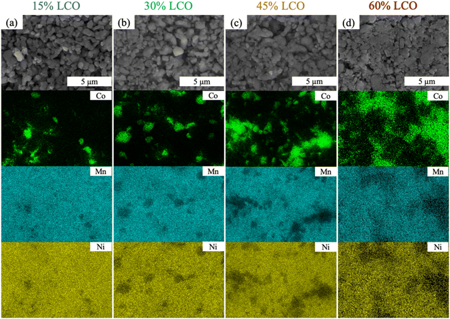 | ||
| Fig. 2 SEM images (first row) and EDS maps (second, third, and fourth row) from AAM electrode cathodes of (a) 15%LCO, (b) 30%LCO, (c) 45%LCO, and (d) 60%LCO. The EDS maps correspond to the same regions as the SEM images and the color scale corresponds to locations where the indicated elements were detected: green for Co (second row), blue for Mn (third row), and yellow for Ni (fourth row). | ||
3.2 Electrochemical characterization
For the AAM LCO electrode (100%LCO) paired with AAM LTO using a voltage window from 1.0 V to 2.85 V (corresponding to approximately 2.56 V to 4.41 V vs. Li/Li+, assuming the OCV of LTO was 1.56 V vs. Li/Li+),52 the first cycle at a slow charge/discharge rate (C/80) attained nearly the same gravimetric discharge capacity (139 mA h g−1 cathode) as the conventional composite cathode cells (initial discharge voltage profile can be found in Fig. 3a). The AAM electrode cell dQ/dV calculated using the initial discharge curve (Fig. 3b) had a small initial peak at ∼2.6 V, which corresponded to the small peak at ∼4.15 V (vs. Li/Li+, AAM treated LCO in conventional composite cell, see Fig. S7b, ESI†). There was a strong peak at 2.3 V, which was consistent with the conventional composite cell data and previous reports.8,12,13 As shown in Fig. 4, at higher rates of C/20, C/10, C/5, and C/2.5, the AAM electrode cell discharge capacity was 112 mA h g−1, 62 mA h g−1, 29 mA h g−1, and 12 mA h g−1, respectively, on an LCO mass basis. Such decrease in capacity was expected to have originated from the ionic transport limitations though the thick electrode microstructure for this material pairing, as has been described thoroughly in previous reports.8–13 Additional cycling voltage profiles and rate capability outcomes can be found in Fig. S8a and S9 (ESI†).
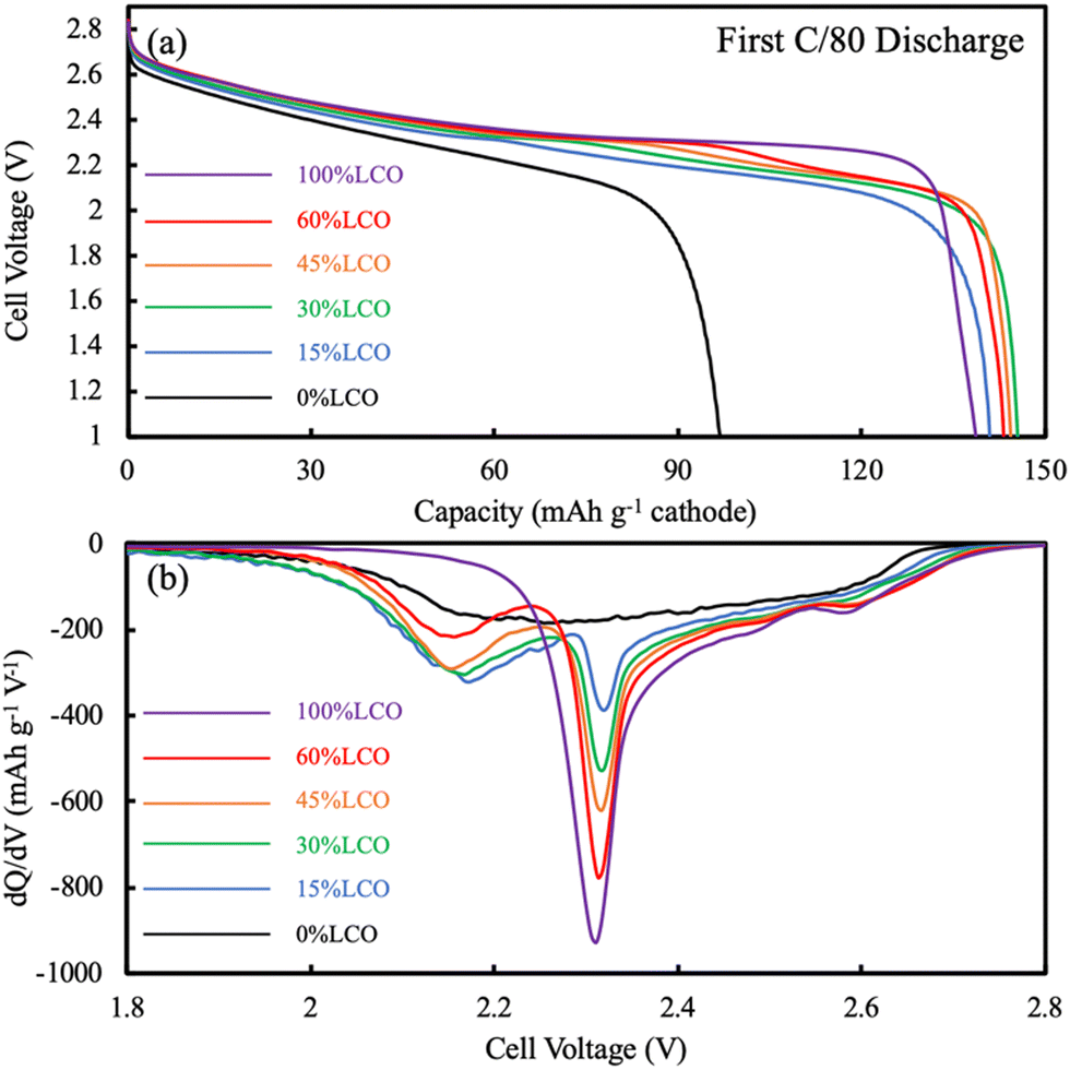 | ||
| Fig. 3 (a) Discharge voltage profiles at low rate for AAM electrode cells containing LTO anodes and cathodes comprised of 100%LCO (purple), 60%LCO (red), 45%LCO (orange), 30%LCO (green), 15%LCO (blue), and 0%LCO (black). The discharge was at a rate of C/80, which was the same rate used for the charge cycle and corresponded to ∼0.282 mA cm−2. (b) The corresponding dQ/dV plots calculated from the discharge results shown in (a). | ||
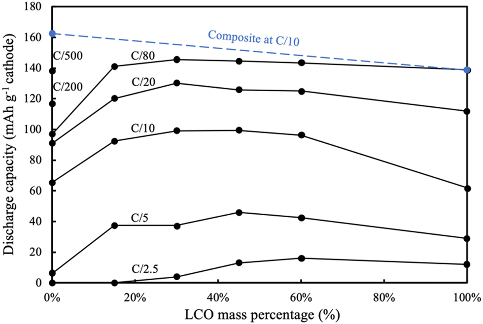 | ||
| Fig. 4 Discharge capacity (gravimetric on cathode mass basis) from rate capability testing of AAM electrode cells comprised of LTO anodes and cathodes with the indicated relative LCO compositions on the x-axis (balance of electroactive material mass was LNMO). The blue dashed line at the top indicates the capacity expected based on the mass of active material in the electrodes and their gravimetric capacity in conventional composite electrodes cycled at a relatively low rate of charge/discharge. For reference, ∼1.13 mA cm−2 was used as C/20 rate for all AAM electrodes. | ||
For the AAM LNMO cathode cell (0%LCO in Fig. 3), the first discharge at C/80 (0.282 mA cm−2) only reached 97 mA h g−1 cathode (Fig. 4). Based on the conventional composite electrode dQ/dV result and the voltage offset from using LTO in the AAM cell, a peak was expected at 2.16 V; however, a sharp dQ/dV peak was not observed for this discharge (Fig. 3b). The first cycle discharge capacity retention of the AAM cell relative to the conventional composite cathode cell for LNMO was 60%, while for LCO it was 99% at C/80. Such differences were hypothesized to result from the much lower electronic conductivity of the LNMO, which has been reported with a range from 10−5 to 10−6 S cm−1 for the pristine material before cycling.31,32 These electronic conductivity values were more than 4 orders of magnitude lower than LCO, where for over 95% of the lithiation range typically accessed for LCO the electronic conductivity was over 10−1 S cm−1.13,56,57 Cells cycled at C/200 and C/500 delivered 117 mA h g−1 LNMO and 138 mA h g−1 LNMO on the first discharge cycle (see Fig. S10 for the first cycle voltage profiles, ESI†), which was 72% and 85% retention relative to conventional composite electrode initial discharge gravimetric capacity. Interestingly, the first charge capacities at C/200 and C/500 were quite similar (169 mA h g−1 and 171 mA h g−1), where the differences (2 mA h g−1 cathode) were much smaller than that of the discharge (21 mA h g−1 cathode). This outcome was consistent with the LNMO material having a variable electronic conductivity as a function of lithiation, where the electronic conductivity increases upon delithiation similar to other layered materials such as LCO.13,56,57 Thus, the charging process may have extracted all available capacity from the LNMO active material, facilitated by the improved electronic conductivity as the material was delithiated. However, as more Li intercalated into the LNMO crystal during discharge, the electronic conductivity would have decreased. This severe drop would have resulted in electronic overpotential which likely limited the electrochemical capacity that was able to be discharged. The later P2D simulations section contains a more detailed discussion of the impacts of LNMO electronic conductivity.
Although LNMO has lower electronic conductivity than LCO, at C/10 the AAM LNMO discharged 63 mA h g−1, which was greater than the pure AAM LCO. This was likely due to a few contributing factors. First, as mentioned earlier it was suspected that LNMO has an increasing electronic conductivity with delithiation, and thus was able to extract that level of capacity at C/10 before reaching extents of lithiation during discharge where the electronic conductivity dropped, and the resulting overpotential limited the ability to deliver additional capacity. Second, another factor beyond electronic conductivity was the potential of the electrochemical reactions for the different cathode materials (e.g., thermodynamic, or OCV, factors). LNMO had an overall lower OCV for electrochemical charge/oxidation compared to LCO. As an example, a large charging voltage plateau region for LCO was ∼0.14 V higher than that of LNMO (see Fig. S7, ESI†). The lower charging potential for extracting lithium and capacity means that after reaching an equivalent charging capacity that LNMO has greater potential range remaining before hitting the cutoff voltage, where the cutoff was the same for all AAM electrode full cells. Thus, the relative thermodynamic driving force for extracting additional capacity on charge at greater charging extents was expected to be greater for LNMO relative to LCO. In addition, porosity of AAM LCO electrodes (∼0.33) was lower than that of LNMO electrodes (∼0.41), likely due to morphology differences for the powders. Thus, the overpotential from ion transport through the electrode microstructure was greater for the LCO electrodes relative to LNMO electrodes. Ion transport through the electrode microstructure has previously been demonstrated to be a major limiting factor for thick AAM electrodes,9,11,13,14 and the higher porosity for the LNMO would improve the relative ionic conductivity of these electrodes. At higher rates such as C/5 the AAM LMNO delivered very low capacity (6 mA h g−1), suggesting the low electronic conductivity of LNMO (0%LCO) was too resistive at that rate to facilitate much of the electrode achieving high extents of lithiation. Voltage profiles and rate capability results starting from C/20 can be found in Fig. S8f and S9 (ESI†).
Closer inspection of the first discharge voltage profile at C/80 (Fig. 3a) revealed that as the LCO content in the AAM electrodes increased, the average discharge voltage also increased. This was a consequence not only of the higher electronic conductivity of LCO compared to LNMO, but the intrinsic properties of the material with regards to the potentials at which the intercalation reactions occur. The relative impact of the voltage of the electrochemical reactions of the different materials can be further informed by examining the dQ/dV of the first discharge voltage profile at C/80 (Fig. 3). As mentioned previously, pure LNMO (0%LCO) had a very broad dQ/dV across the voltage range without a sharp peak. However, even the 15%LCO AAM cathode had a clear dQ/dV peak assigned as arising from the LNMO component at 2.16 V (vs. LTO/anode). As the LCO content in the electrodes was increased from 15%LCO towards 100%LCO, the dQ/dV peak that was due to the LCO component (at ∼2.3 V) increased while the LNMO dQ/dV peak decreased, as would be expected for their changing relative compositions in the electrodes. However, the LNMO peak intensity change was not proportional to the LNMO content, in particular when comparing the dQ/dV peaks for 15%LCO and 30%LCO. This observation may have been due to the more limited improvement in matrix electronic conductivity at these extents of LCO loading, which then did not enable the LNMO to be fully accessible in the electrode for delivering capacity at these discharge rates.
3.3 P2D Simulations and analysis
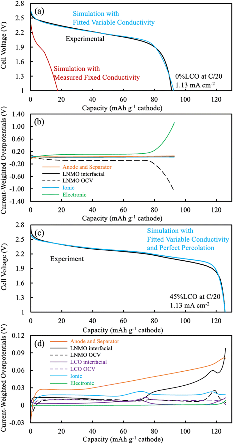 | ||
| Fig. 5 (a and c) Voltage profiles and (b and d) overpotential distributions extracted from P2D simulations of AAM electrode cells. The pure LNMO cathode cell corresponds to (a) and (b) while the 45%LCO corresponds to the results in (c) and (d). All simulations were run for a discharge at C/20 (1.13 mA cm−2). For the discharge simulations in (a) and (c) the blue curve used fitted variable electronic conductivity, the red curve used the measured electronic conductivity, and the experimental outcome is the black curve. The simulated overpotential distributions in (b) and (d) were extracted at different extents of the discharge capacity using the fitted variable electronic conductivity in the model. Note that the y-axis scales in (b) and (d) are of different magnitudes. For (b) and (d), the overpotentials from anode and separator were summed together (orange solid), while all others were from the cathode. The cathode overpotentials were separately LNMO interfacial (black solid), LNMO OCV (black dashed), LCO interfacial (purple solid), LCO OCV (purple dashed), ionic (blue), and electronic (green). | ||
An overpotential distribution analysis throughout the discharge simulation was performed (Fig. 5b), and a detailed introduction of the process associated with such analysis can be found in a previous report.14 In brief, the overpotentials associated with ionic resistance, electronic resistance, interfacial resistance, and OCV differences are calculated at different depths within the cell during the discharge simulation. These overpotentials are then weighted by the electrochemical current being produced at each location, and then summed. Thus, at any given point in the discharge the relative overpotential for each of the resistances mentioned above for the cathode, anode, and separator were calculated. Such analysis provides insights into the factor(s) responsible for deviations between the discharge potential and the thermodynamic maximum potential for a given extent of discharge capacity delivered. In addition, the electrolyte and electrode Li+ concentrations at selected discharge capacities were calculated during the simulation and can be found in Fig. S12 (ESI†).
Due to the limited electronic conductivity of the solid phase (lower than ionic conductivity of electrolyte phase), the initial condition from discharge simulation included a more delithiated region near the current collector for the LNMO electrode (Fig. S12b, ESI†).30 For the first 10 mA h g−1 cathode discharged, due to a combination of the OCV difference across the cathode depth due to the lithiation distribution at the end of charge and the limited electronic conductivity, the intercalation was largely confined near the current collector in the LNMO (Fig. S12b, ESI†). The OCV overpotential contribution was even negative due to the more lithiated LNMO near the current collector, and the low electronic conductivity drove the electronic overpotential to ∼0.08 V (Fig. 5b). As the discharge proceeded up to 79 mA h g−1 cathode, the intercalation preferentially still happened near the current collector side, which was due to the low matrix electronic conductivity arising from the LMNO material. The electronic overpotential reached a plateau of ∼0.11 V, which notably exceeded the other overpotential sources, including the sum of overpotentials from the separator and anode. The OCV overpotential reached a plateau of ∼−0.09 V and resulted from the material being more lithiated near the current collector side first during discharge, and thus net resulted also due to the low electronic conductivity of the LNMO material. For the rest of the discharge process (concluding at 93 mA h g−1 cathode), very little lithiation occurred in the LNMO near the current collector due to the limited capacity still available in this region, which then resulted in more lithiation occurring near the separator. The current had to travel via the electroactive material before reaching the lithiation region near the separator and the electronic conductivity near the current collector had significantly decreased due to that material being near the full lithiation state. These two effects combined to result in the electronic overpotential significantly increasing. In summary, the following processes resulted in the LNMO AAM cathode full cells having relatively low discharge capacity: (i) the low electronic conductivity drove intercalation/lithiation early in the discharge near the current collector region in the cathode; (ii) once the current collector side reached near its capacity limit, more and more current had to pass through this region which had very low electronic conductivity (due to decreasing electronic conductivity with increasing lithiation); and (iii) the electronic overpotential then severely increased, causing the cell voltage to plummet and reach the lower voltage cutoff.
The electrochemical potential of the electrode materials provided the driving force for the electrochemical reactions to occur.30 This was analyzed in the context of the OCV of the materials in the electrode, which varied as a function of charge/discharge time and location as the reactions proceeded. LCO had ∼90% of its capacity above ∼3.8 V (versus Li/Li+), where LNMO had only ∼56% of its capacity above this voltage. Before moving to the same analysis as the one done to the pure LNMO cell, a capacity contribution separately from each material (LNMO and LCO) was extracted from the simulation and can be found in Fig. 6. For the first ∼30 mA h g−1 cathode capacity delivered, both LCO and LNMO contributed roughly similar capacity, which could be attributed to the initially sloped OCV functions for both materials. From ∼30 until ∼60 mA h g−1 cathode capacity delivered, the LCO started to contribute more capacity because it had much more capacity at ∼2.3 V (cell voltage, corresponding to the LCO voltage plateau at ∼3.9 V vs. Li/Li+). From ∼60 until ∼115 mA h g−1 cathode capacity delivered, the LNMO replaced LCO as the major capacity contributor due to its voltage plateau at ∼2.1 V (cell voltage, corresponding to the LNMO voltage plateau at ∼3.7 V vs. Li/Li+). For the final portion of delivered capacity until the end of discharge, both LCO and LNMO approximately equally contributed capacity, due to the sloped OCV function and similar to the early portion of the discharge capacity. It is noted here that the blended electrodes resulted in the electrochemical lithiation during discharge being more distributed throughout the electrode depth during discharge. In contrast, single component electrodes had more localized electrochemical activity as a function of cell depth. It is speculated that spreading out the reaction as a function of electrode depth may have advantages in accommodating the changes in stress/strain that accompany changes in lithium composition in the AAM electrodes. Such mechanical advantages are speculative, but are intended to be investigated in more detail in future work.
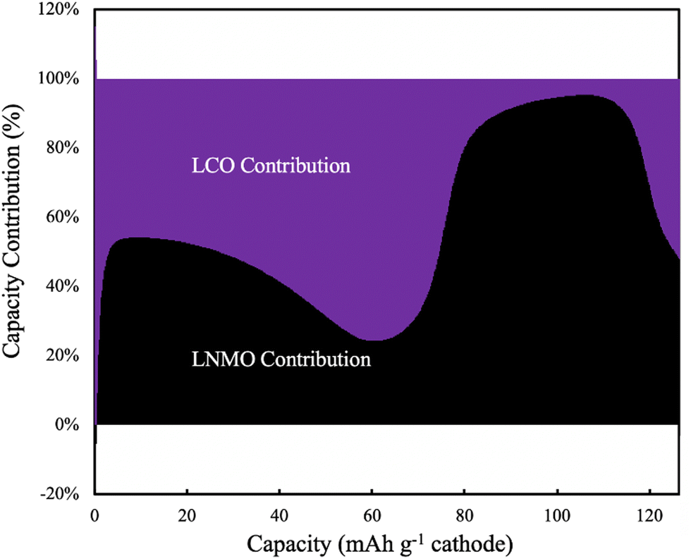 | ||
| Fig. 6 Simulated capacity contribution from LCO (purple) and LNMO (black) at C/20 discharge (1.13 mA cm−2) for the 45%LCO cathode AAM electrode cell. | ||
The same overpotential distribution analysis from the simulation results as was conducted for the LNMO AAM electrode cell was performed for the cell with the 45%LCO cathode and is shown in Fig. 5d. The Li concentration in the electrode for the solid (averaged based on the wt% of LNMO and LCO) and electrolyte phase can be found in Fig. S13 (ESI†). The change in Li electrode concentration of each of LNMO and LCO at selected delivered capacity points is also provided in Fig. S14 (ESI†). For the first 30 mA h g−1 cathode capacity delivered, both LCO and LNMO had slightly more Li intercalated near the separator region. This was in contrast to the pure LNMO case where the initial intercalation was near the current collector and was due to the relatively higher electronic conductivity of the blended material solid electrode compared to the ionic conductivity of the electrolyte. The interfacial overpotential from LNMO was slightly greater than that of the LCO, which originated from the smaller interfacial area of LNMO and smaller reaction rate constant used in the simulation. From 30 until 56 mA h g−1 cathode capacity delivered, the LCO interfacial overpotential increased but that of LNMO decreased, which was because the LCO was in its voltage plateau regions and thus less capacity was provided by LNMO. Correspondingly, much more Li was intercalated into LCO and also more Li was intercalated near the separator region. From 56 until 78 mA h g−1 cathode capacity delivered, the capacity from LCO voltage plateau was nearly depleted. A large amount of Li intercalated into the LCO, but this capacity was concentrated in the current collector region. Such observation was consistent with previous thick AAM electrode reports,11,12,30 where an electrode with a flat OCV curve and relatively higher electronic conductivity (relative to ionic conductivity) resulted in a reaction front which initiated from the separator and propagated towards the current collector. Correspondingly, the ionic overpotential rose and fell depending on whether it was further from or closer to the separator, respectively. From 78 to 110 mA h g−1 cathode capacity delivered, the LNMO interfacial overpotential increased but that of LCO decreased, which was because the LNMO started delivering a larger fraction of the capacity due to now being in the LNMO voltage plateau region. In examining the change in Li electrode concentration, the LNMO accepted more Li, but the reaction was not as concentrated as LCO at the separator side. Such behavior may have resulted due to (i) the electrode electronic conductivity was not as high as when LCO was being discharged because the LCO network was now at a much higher extent of lithiation and correspondingly lower electronic conductivity; (ii) LNMO had slightly smaller reaction rate constant and interfacial area than that of LCO; and (iii) LNMO OCV compared to LCO was more sloped (see Fig. S7, ESI†), and flatter OCV profiles promote sharper reaction propagation gradients.
From 110 mA h g−1 cathode capacity delivered until the end of discharge, a reaction front in the LNMO similar to that observed for LCO earlier was observed. There was also a similar peak that occurred with regards to the ionic overpotential, and more Li was intercalated into the LNMO at the current collector side. Note that the electronic overpotential throughout the discharge was dramatically suppressed from the electronic conductivity enhancement of the blended LCO. The electronic overpotential started to increase at ∼120 mA h g−1 cathode capacity due to the decreasing electronic conductivity of LCO phase. Such decrease in electronic conductivity of LCO led to a decreased voltage, and the resulting voltage was lower than observed experimentally suggesting that the electronic conductivity in the simulation may have been underestimated at high extents of lithiation for the LCO.
3.4 EIS and CCCV analysis
EIS measurements were also conducted as a function of charging voltage for AAM cathodes. The cathodes were paired with Li metal to avoid effects from the lithiation heterogeneity of the LTO AAM anode. The P2D simulations suggested Li inhomogeneity developed as a function of depth in the thick AAM electrodes, thus the charging profile was CCCV, where a long voltage hold of 20 hours was used at each voltage where EIS was conducted to minimize lithiation heterogeneity within the electrodes as a function of depth. It was expected that these the high frequency intercept region from these EIS measurements would provide insights into the relative electronic conductivity changes of the AAM cathodes as a function of delithiation. The high frequency intercept (Rcell) from the Nyquist plot was extracted at each 0.1 V increment of the charging process for the cell. At the high frequency, interfacial and slower diffusive processes were excluded, and the current through the AAM electrode could be treated as a transmission line model,59 where the current partially travelled through the solid AAM electrode and partially travelled through the liquid electrolyte. The relative passage of current was determined by the relative electronic conductivity of AAM electrode and ionic conductivity of liquid electrolyte in the interstitial region of the AAM electrode. However, because the electronic conductivity in the AAM electrodes was expected to vary by orders of magnitude, and could swing from orders of magnitude above and below the ionic conductivity of the liquid electrolyte, quantitatively calculating the AAM electronic conductivity was challenging. In addition, it is noted that the high frequency intercept reflected multiple other contributions which could influence interpreting changes in its magnitude, including the change in electrolyte ionic conductivity due to irreversible side reactions which can change electrolyte concentration upon cycling,60 contact resistance between the current collectors and electrodes, and external cell connections. The Rcell values were fitted using an equivalent circuit model for the lithium half cell, with model and plots shown in Fig. S15 (ESI†).61,62In qualitatively examining the Rcell at different holding voltages (Fig. 7a), all three cells started at ∼10.6 Ω, suggesting the pristine AAM electrode without delithiation had electronic conductivities which were much lower than the electrolyte conductivity, and thus the liquid electrolyte carried the most of the current. Such observation was consistent with the literature reported and measured electronic conductivity data, where the solid LCO and LNMO were both over 2 orders of magnitude lower in electronic conductivity than the ionic conductivity of the liquid electrolyte. Until 3.9 V, the LCO had the largest decrease in Rcell followed by 45%LCO, and the LNMO, implying electronic conductivity increased in all AAM electrodes. Such observation was also consistent with the aforementioned cell data. Between 3.9 V and 4.4 V, all Rcell values increased, which may have been due to reductions in the ionic conductivity of the liquid electrolyte. It was expected that the electrolyte would be consumed by side reactions for both the cathode electrolyte interface (CEI) and solid electrolyte interface (SEI) on the Li foil. SEI would be expected to especially consume electrolyte during the lithium plating which occurred during the charging process. Note that the areal AAM loading was on the order of 100 mg cm−2, thus thick SEI should form during charge and change the electrolyte composition dramatically. The LCO and 45%LCO had very similar trends in Rcell values, which supported the speculation that 45%LCO had a percolated LCO network which resulted in an electronic conductivity similar in magnitude to pure LCO. The increase in Rcell for both LCO and 45%LCO at higher voltages had smaller increases than the LNMO AAM electrode cell. This would be consistent with lower electronic conductivity for the LNMO because for that material a higher fraction of the current must travel through the liquid electrolyte, which would result in a greater Rcell increase if the electrolyte concentration changed and the resulting electrolyte conductivity decreased.
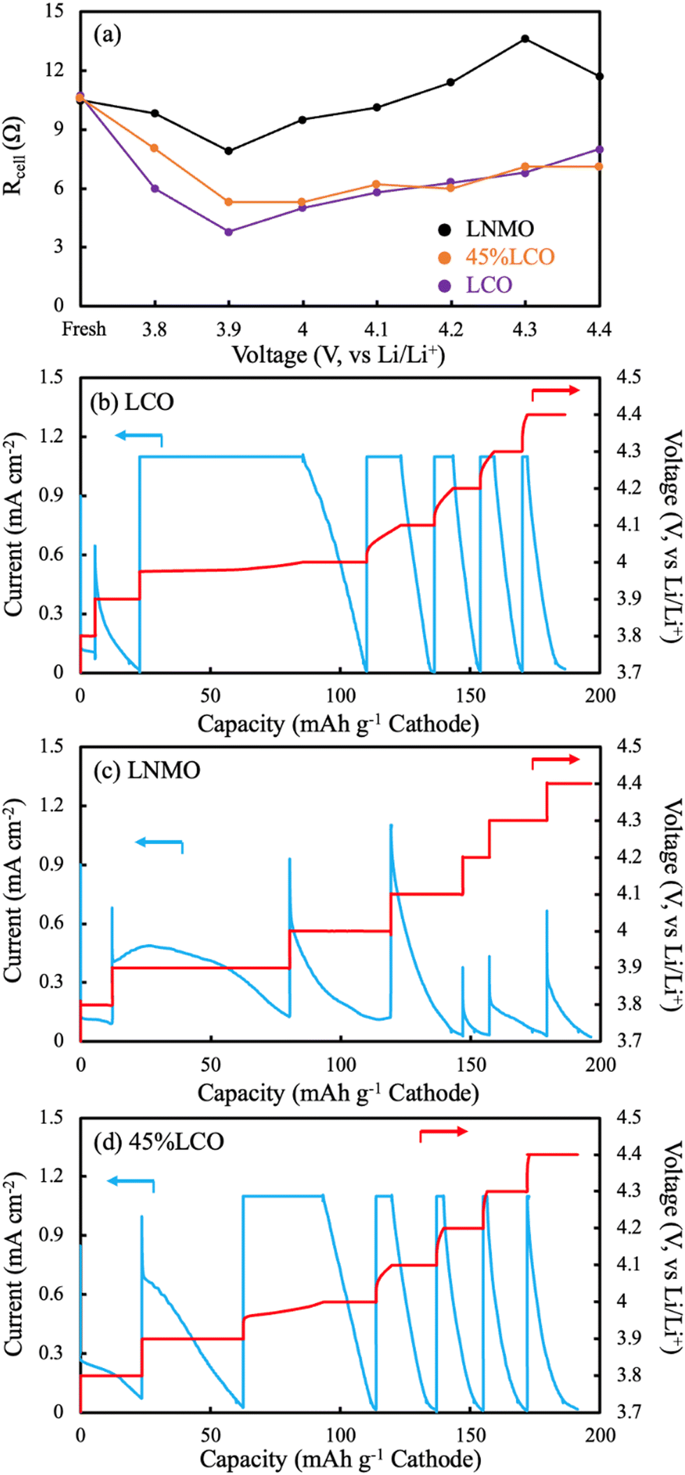 | ||
| Fig. 7 (a) Rcell as a function of voltage for AAM LNMO (black), AAM 45%LCO (orange), and AAM LCO (purple). Values were obtained by fitting EIS Nyquist plots. EIS was conducted after the voltage hold step of a CCCV chare of a cell with the indicated cathode paired with a lithium metal anode. The CCCV charge outcomes are displayed for the relevant cells with (b) LCO, (c) LNMO, and (d) 45%LCO, where red and blue curves represent the voltage and the current density, respectively. | ||
CCCV profiles (Fig. 7b–d) were also evaluated for the different AAM electrode cells. For LCO, only a small capacity was achieved below 3.9 V, which was attributed to the relatively low electronic conductivity at the extent of lithiation below this potential and the relatively low amount of capacity for LCO at this lower redox potential. Above 3.9 V, the charging capacity from during the CC steps in the experiment were much greater, suggesting the increased electronic conductivity of LCO after delithiation had facilitated less polarization from that process within the cell.
For LNMO, nearly all capacity occurred during the CV step until 4.4 V. One specific observation of note was the CV step at 3.9 V, where there was an initial increase in current followed by a decrease. In most cases for a CCCV discharge, the current is supposed to exponentially decay during the CV step. Such observation was additional support that the electronic conductivity increased for LNMO with delithiation. However, this electronic conductivity increase was still insufficient to provide much charge capacity during the subsequent CC step. A separate identically processed cell was charged with CCCV mode all the way to 4.4 V (CCCV profile can be found in Fig. S16, ESI†) with half of the current density. The voltage initially spiked to ∼4.0 V (∼0.3 V above the potential from the same material processed into a composite electrode), then decreased down to ∼3.9 V, and finally more gradually increased to 4.4 V. There was no material activation process in the identical material evaluated in conventional composite electrodes at C/10 (Fig. S7, ESI†). Thus, this initial voltage spike and then decline on charge was attributed to the LNMO electronic conductivity effect on the electrode matrix electronic conductivity as a function of the extent of lithiation.
The 45%LCO AAM electrode had similar CCCV patterns to the LCO AAM electrode, where below 3.9 V there was minimal capacity from CC mode. Above 4.0 V, the charge capacities during CC steps were much greater. These observations were also consistent with the aforementioned trend where 45%LCO was expected to approach LCO AAM electrode electronic conductivity due to LCO material percolation.
4. Conclusions
In this report, AAM electrode full cells were fabricated where the cathode was either all LCO, all LNMO, or a blend of the two components. Pure LCO had been previously reported as an AAM cathode material and has advantages particularly with regards to electronic conductivity because within AAM electrodes the electrons must transport through the electroactive material itself in the electrode matrix. LNMO served as a model alternative layered phase metal oxide material, where the gravimetric capacity is higher than LCO, but the electronic conductivity especially at high extents of lithiation is much lower. Pure LNMO AAM electrodes resulted in cells with high polarization and low capacity and rate capability during discharge. Blends of LNMO and LCO were investigated with the aim of forming a percolated network of LCO to conduct the electrons through the cathode matrix. Experimental results suggested the LCO and LMNO remained segregated as separate phase particles during processing, and that the addition of LCO significantly improved the discharge capacity and rate capability of AAM electrode cells containing these cathodes. To provide further support for the role of LCO in the improved electrochemical outcomes for the AAM electrodes, P2D simulations were conducted. The P2D simulations further supported that the source of high voltage drops and capacity limitations for pure LNMO AAM electrodes was the limited electronic conductivity of the material. After modification of the electronic conductivity as a function of lithiation, the simulations were able to match the experimental polarization curves well and provide further insights into the discharge process for the blended LCO and LNMO electrodes. Additional EIS and CCCV analyses were performed, which were consistent with the role of electronic conductivity of the AAM electrodes with regards to dependence on electrode composition and extent of delithiation. This study provides support for the use of a percolated secondary phase to enable the use of low electronic conductivity electrode materials in AAM electrode cells at reasonable rates, provided that undesirable interfacial phases do not form during the processing of these multicomponent all active material electrodes.Conflicts of interest
There are no conflicts to declare.Acknowledgements
This research was supported by the National Science Foundation, via grants CMMI-1825216 and CBET-1652488.References
- J. B. Goodenough and Y. Kim, Chem. Mater., 2010, 22, 587–603 CrossRef CAS.
- J. B. Goodenough and K. S. Park, J. Am. Chem. Soc., 2013, 135, 1167–1176 CrossRef CAS PubMed.
- D. Deng, Energy Sci. Eng., 2015, 3, 385–418 CrossRef.
- N. Nitta, F. Wu, J. T. Lee and G. Yushin, Mater. Today, 2015, 18, 252–264 CrossRef CAS.
- V. Etacheri, R. Marom, R. Elazari, G. Salitra and D. Aurbach, Energy Environ. Sci., 2011, 4, 3243–3262 RSC.
- M. E. Sotomayor, C. de la Torre-Gamarra, B. Levenfeld, J. Y. Sanchez, A. Varez, G. T. Kim, A. Varzi and S. Passerini, J. Power Sources, 2019, 437, 226923 CrossRef CAS.
- K. G. Gallagher, S. E. Trask, C. Bauer, T. Woehrle, S. F. Lux, M. Tschech, P. Lamp, B. J. Polzin, S. Ha, B. Long, Q. Wu, W. Lu, D. W. Dees and A. N. Jansen, J. Electrochem. Soc., 2016, 163, A138–A149 CrossRef CAS.
- J. P. Robinson, J. J. Ruppert, H. Dong and G. M. Koenig, J. Appl. Electrochem., 2018, 48, 1297–1304 CrossRef CAS.
- Z. Nie, R. Parai, C. Cai, C. Michaelis, J. M. LaManna, D. S. Hussey, D. L. Jacobson, D. Ghosh and G. M. Koenig, J. Electrochem. Soc., 2021, 168, 060550 CrossRef CAS.
- Z. Nie, R. Parai, C. Cai, D. Ghosh and G. M. Koenig, Mol. Syst. Des. Eng., 2021, 6, 708–712 RSC.
- Z. Nie, S. Ong, D. S. Hussey, J. M. Lamanna, D. L. Jacobson and G. M. Koenig, Mol. Syst. Des. Eng., 2020, 5, 245–256 RSC.
- Z. Nie, P. McCormack, H. Z. Bilheux, J. C. Bilheux, J. P. Robinson, J. Nanda and G. M. Koenig, J. Power Sources, 2019, 419, 127–136 CrossRef CAS.
- C. Cai, Z. Nie, J. P. Robinson, D. S. Hussey, J. M. LaManna, D. L. Jacobson and G. M. Koenig, J. Electrochem. Soc., 2020, 167, 140542 CrossRef CAS PubMed.
- C. Cai, D. Hensley and G. M. K. Jr, J. Energy Storage, 2022, 54, 105218 CrossRef.
- A. Mistry, S. Trask, A. Dunlop, G. Jeka, B. Polzin, P. P. Mukherjee and V. Srinivasan, J. Electrochem. Soc., 2021, 168, 070536 CrossRef CAS.
- M. Ebner, D. W. Chung, R. E. García and V. Wood, Adv. Energy Mater., 2014, 4, 1–6 Search PubMed.
- B. Tjaden, S. J. Cooper, D. J. Brett, D. Kramer and P. R. Shearing, Curr. Opin. Chem. Eng., 2016, 12, 44–51 CrossRef.
- M. Doyle, J. Electrochem. Soc., 1996, 143, 1890 CrossRef.
- C. Cai and G. M. Koenig, Electrochim. Acta, 2021, 401, 139484 CrossRef.
- R. Elango, A. Nadeina, F. Cadiou, V. De Andrade, A. Demortière, M. Morcrette and V. Seznec, J. Power Sources, 2021, 488, 229402 CrossRef CAS.
- A. N. Mistry, K. Smith and P. P. Mukherjee, ACS Appl. Mater. Interfaces, 2018, 10, 6317–6326 CrossRef CAS PubMed.
- L. Leyssens, B. Vinck, C. Van Der Straeten, F. Wuyts and L. Maes, Toxicology, 2017, 387, 43–56 CrossRef CAS PubMed.
- S. Ahmed, P. A. Nelson, K. G. Gallagher, N. Susarla and D. W. Dees, J. Power Sources, 2017, 342, 733–740 CrossRef CAS.
- N. Co, I. Saadoune and C. Delmas, J. Solid State Chem., 1998, 136, 8–15 CrossRef.
- R. Amin, D. B. Ravnsbæk and Y.-M. Chiang, J. Electrochem. Soc., 2015, 162, A1163–A1169 CrossRef CAS.
- M. Park, X. Zhang, M. Chung, G. B. Less and A. M. Sastry, J. Power Sources, 2010, 195, 7904–7929 CrossRef CAS.
- J. Molenda, J. Marzec, K. Świerczek, W. Ojczyk, M. Ziemnicki, M. Molenda, M. Drozdek and R. Dziembaj, Solid State Ionics, 2004, 171, 215–227 CrossRef CAS.
- J. Molenda, J. Marzec, K. Świerczek, D. Pałubiak, W. Ojczyk and M. Ziemnicki, Solid State Ionics, 2004, 175, 297–304 CrossRef CAS.
- S. Yaniamura, H. Koshika, M. Nishizawa, T. Matsue and I. Uchida, J. Solid State Electrochem., 1998, 2, 211–215 CrossRef.
- C. Cai, Z. Nie and G. M. Koenig, Mater. Adv., 2022, 4200–4212 RSC.
- P. S. Kumar, A. Sakunthala, M. Prabu, M. V. Reddy and R. Joshi, Solid State Ionics, 2014, 267, 1–8 CrossRef.
- N. Murali, K. Vijaya Babu, K. Ephraim Babu and V. Veeraiah, Mater. Sci. Pol, 2016, 34, 404–411 CrossRef CAS.
- J. P. Robinson, P. D. Kichambare, J. L. Deiner, R. Miller, M. A. Rottmayer and G. M. Koenig Jr, J. Am. Ceram. Soc., 2018, 101, 1087–1094 CrossRef CAS.
- H. Dong and G. M. Koenig, CrystEngComm, 2020, 22, 1514–1530 RSC.
- C. Cai, H. Dong and G. M. Koenig, Powder Technol., 2021, 394, 214–224 CrossRef CAS.
- H. Dong and G. M. Koenig, J. Mater. Chem. A, 2017, 5, 13785–13798 RSC.
- T. F. Fuller, J. Electrochem. Soc., 1994, 141, 1 CrossRef CAS.
- M. Doyle, T. F. Fuller and J. Newman, J. Electrochem. Soc., 1993, 140, 1526–1533 CrossRef CAS.
- Z. Lu, Z. Chen and J. Dahn, Chem. Mater., 2003, 2, 3214–3220 CrossRef.
- M. Holzapfel, C. Haak and A. Ott, J. Solid State Chem., 2001, 156, 470–479 CrossRef CAS.
- R. B. Nuernberg, N. M. P. Machado, M. Malki and M. Neyret, J. Nucl. Mater., 2021, 546, 152777 CrossRef CAS.
- J. Li, R. Doig, H. Liu, G. Botton and J. R. Dahn, J. Electrochem. Soc., 2016, 163, A2841–A2848 CrossRef CAS.
- J. Li, R. Doig, J. Camardese, K. Plucknett and J. R. Dahn, Chem. Mater., 2015, 27, 7765–7773 CrossRef CAS.
- R. M. Ziff and S. Torquato, J. Phys. A: Math. Theor., 2017, 50, 085001 CrossRef.
- S. Venkatraman and A. Manthiram, Chem. Mater., 2003, 15, 5003–5009 CrossRef CAS.
- J. Mao, W. Tiedemann and J. Newman, ECS Trans., 2014, 58, 71–81 CrossRef.
- G. M. Koenig, I. Belharouak, H. Deng, Y. K. Sun and K. Amine, Chem. Mater., 2011, 23, 1954–1963 CrossRef CAS.
- J. I. Goldstein, D. E. Newbury, J. R. Michael, N. W. M. Ritchie, J. H. J. Scott and D. C. Joy, Scanning electron microscopy and X-ray microanalysis, Springer, 2017 Search PubMed.
- J. Cho, Y. J. Kim and B. Park, J. Electrochem. Soc., 2001, 148, A1110 CrossRef CAS.
- Y. Lyu, X. Wu, K. Wang, Z. Feng, T. Cheng, Y. Liu, M. Wang, R. Chen, L. Xu, J. Zhou, Y. Lu and B. Guo, Adv. Energy Mater., 2021, 11, 1–29 Search PubMed.
- Z. Qi and G. M. Koenig, ChemistrySelect, 2016, 1, 3992–3999 CrossRef CAS.
- B. Zhao, R. Ran, M. Liu and Z. Shao, Mater. Sci. Eng. R Rep., 2015, 98, 1–71 CrossRef.
- W. Liu, M. Qin, L. Xu, S. Yi, J. Deng and Z. Huang, Trans. Nonferrous Met. Soc. China, 2018, 28, 1626–1631 CrossRef CAS.
- R. Fantin, E. Trevisanello, R. Ruess, A. Pokle, G. Conforto, F. H. Richter, K. Volz and J. Janek, Chem. Mater., 2021, 33, 2624–2634 CrossRef CAS.
- K. S. Lee, S. T. Myung, J. S. Moon and Y. K. Sun, Electrochim. Acta, 2008, 53, 6033–6037 CrossRef CAS.
- S. Levasseur, M. Ménétrier, E. Suard and C. Delmas, Solid State Ionics, 2000, 128, 11–24 CrossRef CAS.
- I. Saadoune and C. Delmas, J. Mater. Chem., 1999, 9, 1135–1140 RSC.
- J. B. Goodenough, Prog. Solid State Chem., 1971, 5, 145–399 CrossRef CAS.
- R. Morasch, J. Keilhofer, H. A. Gasteiger and B. Suthar, J. Electrochem. Soc., 2021, 168, 080519 CrossRef CAS.
- X. Wu, T. Liu, Y. Bai, X. Feng, M. M. Rahman, C. J. Sun, F. Lin, K. Zhao and Z. Du, Electrochim. Acta, 2020, 353, 136453 CrossRef CAS.
- W. Choi, H. C. Shin, J. M. Kim, J. Y. Choi and W. S. Yoon, J. Electrochem. Sci. Technol., 2020, 11, 1–13 CrossRef CAS.
- F. Schipper, H. Bouzaglo, M. Dixit, E. M. Erickson, T. Weigel, M. Talianker, J. Grinblat, L. Burstein, M. Schmidt, J. Lampert, C. Erk, B. Markovsky, D. T. Major and D. Aurbach, Adv. Energy Mater., 2018, 8, 1701682 CrossRef.
Footnote |
| † Electronic supplementary information (ESI) available. See DOI: https://doi.org/10.1039/d2ya00269h |
| This journal is © The Royal Society of Chemistry 2023 |