
Water flow and finger-tapping mediated piezoelectric energy generation using a natural hematite-based flexible PVDF-HFP membrane†
Saheli
Ghosh
a,
Dhananjoy
Mondal
 a,
Shubham
Roy
b,
Jhilik
Roy
ac,
Souravi
Bardhan
d,
Ayan
Mazumder
a,
Neelanjana
Bag
a,
Ruma
Basu
c and
Sukhen
Das
*a
a,
Shubham
Roy
b,
Jhilik
Roy
ac,
Souravi
Bardhan
d,
Ayan
Mazumder
a,
Neelanjana
Bag
a,
Ruma
Basu
c and
Sukhen
Das
*a
aDepartment of Physics, Jadavpur University, Kolkata-700032, India. E-mail: sdasphysics@gmail.com; Tel: +91 9433091337
bShenzhen Key Laboratory of Advanced Functional Carbon Materials Research and Comprehensive Application, Shenzhen Key Laboratory of Flexible Printed Electronics Technology, and School of Science, Harbin Institute of Technology, Shenzhen 518055, China
cDepartment of Physics, Jogamaya Devi College, Kolkata-700026, India
dDepartment of Environmental Science, Netaji Nagar College for Women, Kolkata-700092, India
First published on 4th September 2023
Abstract
Energy demand is increasing exponentially nowadays, which is the primary cause of the burning of fossil fuels, creating enormous amounts of environmental degradation. To arrest this, there is an emerging need for clean and green technologies. Herein, piezoelectric materials have become a favourite choice among scientists. Previously, many groups have exploited this fascinating technology by imparting pressure from different available sources. This article deals with gadolinium (Gd)-incorporated naturally occurring hematite nanocrystals, which show an efficient piezoelectric effect when incorporated into a PVDF-HFP polymer. In reality, PVDF-HFP is capable of producing nominal piezoelectric polarization (40–60% β-polarization), which in our case is found to be around 80.3%. Such elevated polarizability helps to generate piezoelectric power under water flow or finger tapping. This reported material is not only flexible and bendable but can also produce maxima of 16.92 V and 0.52 μA instantaneous voltage and current, respectively, under simple finger tapping, but 8 V under flowing water. Moreover, these phenomena have been discussed and analyzed in great depth by involving various characterization tools such as XRD, FESEM, TEM, FTIR, and zeta potential. This is probably the first time that a rare-earth-incorporated natural nano-rock mineral has been used to fabricate such a multifunctional device.
1. Introduction
The requirements of energy harvesting and harnessing energy from new and innovative techniques is a blossoming field of research since energy is indispensable for all aspects of life. Since conventional energy is highly dependent on non-renewable fossil fuels like coal, natural gas, and crude oil, their extensive use has jeopardized their availability in the world, resulting in increased inflation and skyrocketing fuel prices.1,2 Moreover, the widespread use of such fossil fuels has also resulted in problems of global warming and environmental pollution, eventually upsetting the Earth's carbon budget.3 Hence, such environmental and economic crises have pushed the world to opt for alternative, cost-effective sustainable energy sources feasible for real-life applications.4,5 Several alternative techniques for energy production have been implemented,6 but among them, energy harvesting from any vibrational or mechanical source has gained immense interest7 due to their better reliability and scalability, sustainable nature, enhanced energy density, self-powered nature, and facile and economical fabrication process compared to other methods.6,8–10Piezo-responsive materials are the front-runners in this scenario as energy-harvesting materials, although some of them require expensive raw materials or generate secondary pollution.11 In the piezoelectric effect, mechanical energy is converted to electrical energy or vice versa.12,13 Several piezoelectric materials are used to harvest energy from mechanical stress, like perovskite, metal oxide nanoparticles, quantum dots, polymers, etc.14,15 Currently, extensive research is devoted to the development of sustainable, cheaper, and commercially feasible energy harvesters that can harvest energy from any mechanical movement.16 Hence, harvesting energy from continuously available mechanical forces like sea waves, waterfalls, streams, etc. can not only reduce dependency on non-renewable resources but also be a futuristic solution to the energy crisis. Furthermore, the usage of widely available natural materials for the development of piezoelectric materials can effectively reduce production costs. Hence this work aims to develop a piezoelectric material from cost-effective sources. A self-poled piezoelectric membrane made of a Gd-incorporated natural hematite (α-Fe2O3) decorated PVDF-HFP polymer has been synthesized. This synthesized piezoelectric material is cost-effective, as the hematite used in this study is naturally formed and one of the most commonly found iron ores.17 A robust and flexible membrane made of this material is therefore used to fabricate an energy harvesting device, which can efficiently generate a high open circuit output voltage under finger impression as well as under water flow. Energy production from an unconventional type of mechanical energy source like water flow made our fabricated device into a futuristic piezoelectric energy harvester.
Here the characteristics of this polymer nanocomposite (hematite NP-based PVDF-HFP membrane) have been studied by using X-ray diffraction (XRD), a field-effect scanning microscope (FESEM), and Fourier transform infrared spectroscopy (FTIR). TGA was further employed to determine mass loss over a range of temperature. The electrical characteristics here illuminate the degree of piezoelectric polarization and show it to be a potential piezoelectric material. The piezo-response was further used to harness electrical energy from mechanical perturbation. Then the efficiency of the nanocomposite polymer was confirmed through experimental methods, which show it may be advantageous for future “green energy” harvesting applications.
2. Experimental
2.1. Materials
The naturally formed hematite (α-hematite), was obtained from Bharat Engineering, Kolkata. Gadolinium oxide (Gd2O3) powder, dimethylformamide (DMF) (HPLC grade), and aqueous ammonia solution (25%) were purchased from Merck, India. Poly(vinylidene fluoride-hexafluoropropylene) (PVDF-HFP) pellets were purchased from Sigma-Aldrich, Germany. All the reagents used were of analytical grade. Millipore water with a resistivity of 18.2 MΩ cm was used throughout the experiments.2.2. Synthesis procedure
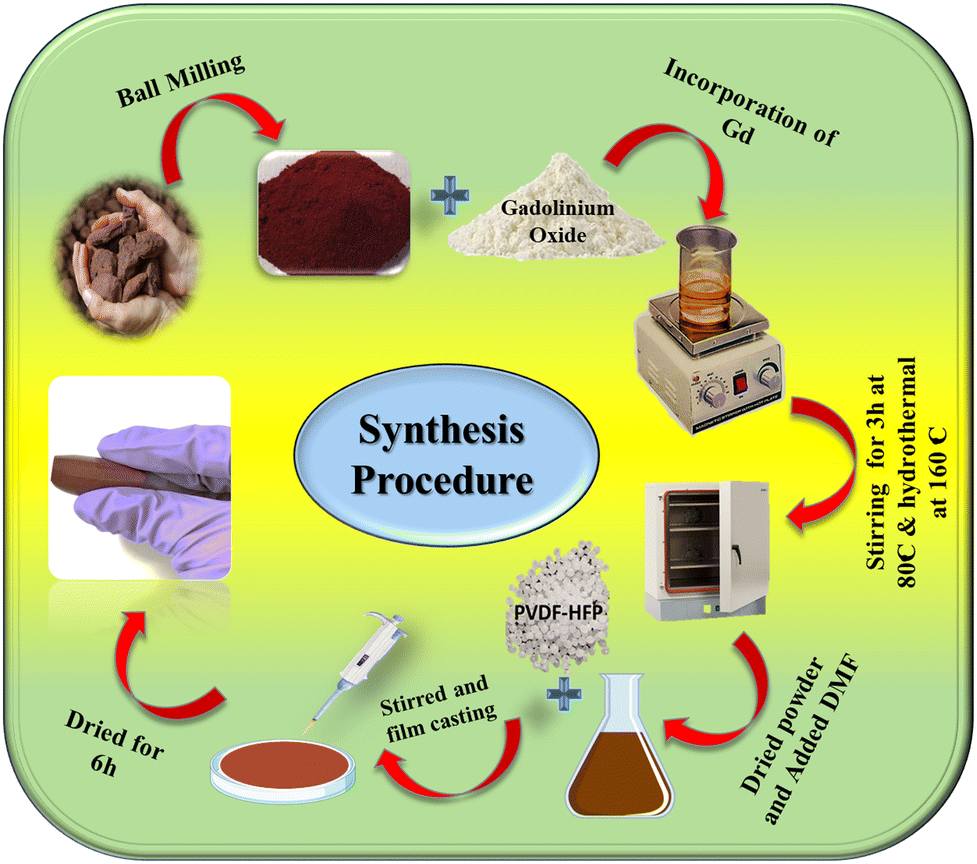 | ||
| Scheme 1 Schematic representation of the synthesis procedure. | ||
2.3. Characterisation techniques
The synthesized nanocomposite membranes were characterized by several methods to study their properties. X-ray diffraction was performed using a Bruker AXS D8 (Wisconsin, USA) diffractometer to analyze the structural and microstructural evolutions of the synthesized samples.18 The diffractometer with a Cu Kα target of 1.5418 Å was operated at a current of 35 mA and a voltage of 35 kV, and at a scan rate of 3 s per step. To investigate the physicochemical properties and the microstructural parameters of mechanically ground hematite, Rietveld refinement was performed by using the MAUD (Material Analysis Diffraction) v2.94 software package.19 A standard cif file (crystallographic information file) for hematite (AMCSD file no. 1011240) was used for refinement of the experimental diffractograms. Primarily, the Caglioti PV function and Gaussian broadening were applied for calibration, and background parameters were also refined. It was found that the experimental diffractogram is well-fitted with promising fitting coefficients over the theoretical data and many microstructural parameters, including cell dimension, crystal size, and microstrain were improved. The VESTA (Visualisation for Electronic and Structural Analysis) program v3.5.2 was used to visualize the bonding networks and microstructures of the unit cell. The X-ray diffraction of the Gd-incorporated hematite-based nanocomposite membrane was also studied. The nanocomposite membrane shows that the β-phase of PVDF at 20.2° increases with doping concentration and is found to be a maximum in PVGF2.5. Fourier transform infrared (FTIR) spectroscopy was employed for analysis of the bonding network as well as the β-phase nucleation of the membrane in the wavenumber region 500–4000 cm−1.20 The morphology of the Gd-incorporated hematite and PVGF0, PVGF2.5, and PVGF5 films was studied and visualized with an INSPECT F50 field-effect scanning electron microscope (FESEM) (FEI, Netherlands) at an accelerating voltage of 10–20 kV.21 The film was set on carbon tape and sputter coated with gold prior to the experiment. Energy-dispersive X-ray spectroscopy (EDS), with a Supra 55 (ZEISS) attached to the FESEM, was performed to check the purity by determining the elemental constituents of the sample. A JEM-2100 Plus transmission electron microscope (TEM) operating at 200 kV was used to visualize the detailed morphology.22 To determine the thermodynamic properties and stability, TGA-DTA analysis23 was performed using a DTG-60H Shimadzu at increasing temperature from 10 °C to 150 °C at a heating rate of 10 °C min−1 under a nitrogen atmosphere. The surface charge of the nanoparticles was determined from zeta potential analysis using a Malvern 167 Zetasizer. The powdered nanoparticle sample was well dispersed in distilled water (1 mg mL−1) using ultrasonication for 30 min.3. Results and discussion
3.1. Physical characterisation
X-ray diffraction was employed to analyse the structural and microstructural parameters of the synthesized materials.24 The XRD patterns of the hematite nanoparticles and Gd-incorporated hematite nanoparticles have been illustrated in Fig. 1(a and b). It was observed that all the diffraction peaks of hematite NPs (nanoparticles) are well matched with JCPDS card no 72–0469. Thus, the absence of any undesirable maxima in the diffraction pattern confirms the purity of the hematite NPs. Even after doping with 5% Gd3+ the peak positions do not alter, suggesting successful doping of Gd3+ ions into the matrix of hematite NPs.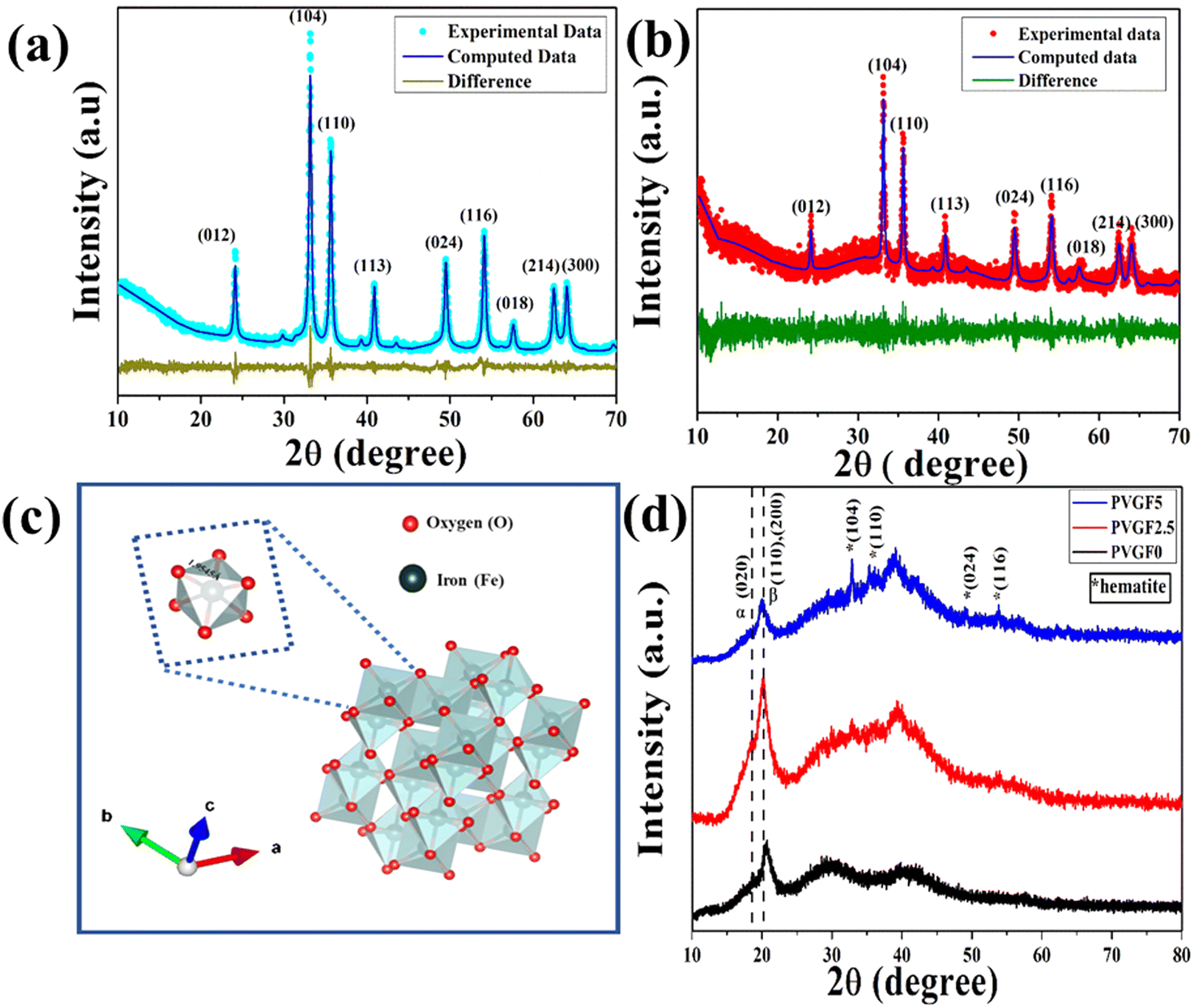 | ||
| Fig. 1 (a) and (b) Experimental and computed XRD patterns of natural α-hematite and Gd-incorporated α-hematite, respectively. (c) Unit cells of Gd-incorporated α-hematite. (d) XRD patterns of natural Gd-incorporated α-hematite nanocomposite membranes suggesting that incorporation of nanocomposite into the polymer matrix enhances the polar phase, finding a maximum in PVGF2.5. | ||
Cell dimensions of both a and b of 5.034 Å and c of 13.745 Å were found from the Rietveld refinement and the unit cell was visualized with Vesta v3.4.3 (visualization for electronic and structural analysis) software [Fig. 1(c)]. It was observed that due to the incorporation of Gd3+, the microstrain had increased from 1.3 × 10⁻⁴ to 9.0 × 10⁻⁴ as Gd3+ is larger than Fe3+, creating excessive stress during the substitution of host ions and thus forming defects in the lattice structure.25,26 Along with microstrain, it was found that oxygen vacancies had been created in the doped NPs owing to such cationic substitution. These alterations in microstrain and oxygen vacancies significantly enhanced the physicochemical properties of the doped NPs.27,28
The XRD diffractograms of Gd-doped hematite-incorporated PVDF membranes have been depicted in Fig. 1(d). The peaks at 18.3° and 20.2° represent the non-polar α-phase and polar β-phase, respectively, of the nanocomposite films.29 The peak at 20.2° has been enhanced after the incorporation of nanocomposite into the PVDF matrix and was found to be a maximum for PVGF2.5. This implies that the incorporation of nanocomposite in the PVDF matrix enhanced its polar β-phase. The enhancement of the polar phase in the PVGF2.5 membrane made it suitable for applications that are modulated by the polarizing effects of membranes, like piezoelectricity.
FESEM and TEM were employed to study the morphological parameters, particle size, etc.30 The structure of the Gd-doped hematite displayed a hexagonal structure, as evident from the TEM micrographs. The size distribution curve was prepared by employing ImageJ software to determine the particle size, which suggests ranges of NPs from 3 to 6 nm, with the median at 5 nm (Fig. 2b).
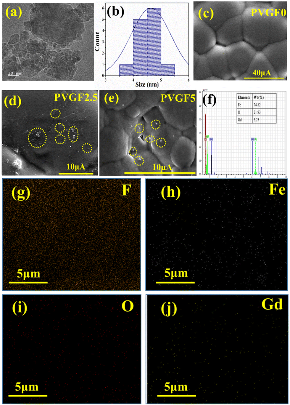 | ||
| Fig. 2 (a) and (b) TEM image and the size distribution curve of Gd-incorporated α-hematite. (c)–(e) FESEM micrographs of PVGF0, PVGF2.5, PVGF5. (f) EDX images Gd-incorporated hematite NPs. (g)–(j) Mapping of the PVGF2.5 membrane suggesting the homogeneous distribution of doped-Gd-incorporated hematite in the PVDF matrix. The carbon distribution of the membrane is not shown due to the use of carbon tape during the EDS mapping measurement. | ||
The FESEM of the membrane in Fig. 2c illustrates the smooth and homogeneous surface in the pristine PVDF (PVGF0) membrane, which becomes rough and spherulite in nature after doping with Gd-doped hematite NPs. PVGF5 [Fig. 2(e)] shows a more perturbed and rougher surface than PVGF2.5 [Fig. 2(d)] due to enhancement of the dopant in the PVDF matrix.31,32 From the spherulite nature of the micrographs, it is evident that β-phase formation in PVGF2.5 and PVGF5 is due to the interaction between the Gd-doped hematite and the CH2–CF2 moiety of the PVDF polymer chain.31,33
Elemental composition analysis was performed with EDS which depicts the stoichiometric ratio of Fe, O, and Gd in the doped hematite NPs. It was found that Gd showed 3.25 wt% instead of 5% doping in the nanocomposite due to improper attachment of some Gd3+ ions in the hematite NPs and these were washed out by centrifugation [Fig. 2(f) and Fig. S4, ESI†]. The nanocomposite was incorporated into the PVDF matrix at 2.5 and 5 wt%. By performing the percentage calculation, it was found that in the PVGF2.5 membrane, Gd is present at 0.07% whereas in PVGF5, Gd is present at 0.14%. The mapping data of PVGF2.5 depicted homogeneous distributions of Fe, O, and Gd in the PVDF matrix in the proper stoichiometric ratio [Fig. 2(g–j)]. The C contained in the PVDF membrane is not found in the mapping data since it was eliminated because of the use of carbon tape for attachment in the EDS measurement.
The zeta potential was evaluated to understand the surface charge of the hematite NPs and their modified counterparts. The naturally formed hematite exhibits a negative surface charge (−3.75 mV) (S3 in ESI†). Incorporation of a very small amount of rare earth metal in its matrix generates stress and microstrain, as evident from the crystallographic refinement. Such stress creates oxygen vacancies in the hematite matrix and creates active sites. The electronegative oxygen vacancies enhance the surface charge of the nanocomposite to +12.3 mV [Fig. 3(e)]34,35
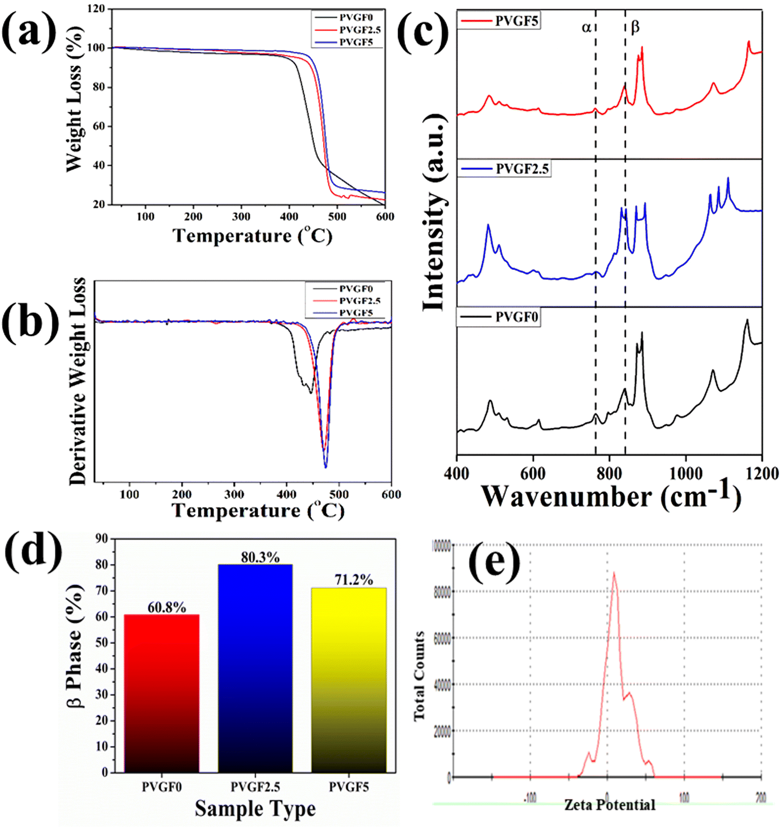 | ||
| Fig. 3 (a) Percentage weight losses of nanocomposite membranes. (b) Derivative weight loss of the nanocomposite membranes, suggesting better stability in doped membranes. (c) FTIR spectroscopy of PVGF0, PVGF2.5, and PVGF5, showing polar phase enhancement after nanocomposite inclusion into the polymer matrix. (d) Percentage β-phase of samples PVGF0, PVGF2.5, and PVGF5. (e) The zeta potential of Gd-incorporated hematite shows a high positive surface charge. | ||
FTIR was employed to determine bonding networks of the nanocomposite membranes and to confirm the formation of β-phase nucleation due to doping36 and is depicted in Fig. 3(c). The absorbance bands observed at 532 cm−1 (–CF2 bending), 615 cm−1 (–CF2 bending), 762 cm−1 (skeletal bending), and 794 and 976 cm−1 (–CH2 rocking) are from the α-phase of PVDF which is being reduced in PVGF2.5 and PVGF5.37 The peaks at 484 cm−1 (–CF2 deformation), 510 cm−1 (–CF2 stretching), 602 cm−1 (–CF2 wagging), and 841 cm−1 (–CF2 stretching, –CH2 rocking and skeletal C–C stretching) are β-phase absorbance bands which increase with NP incorporation and are found to be maxima in PVGF2.5. In the case of PVGF5, the β-phase is slightly reduced compared to PVGF2.5 but the percentage of β-phase is more than that in PVGF0.37,38 The Lambert–Beer law was used to calculate the fraction of electroactive β-phase according to the relation:
 | (1) |
To determine the thermal stability of the nanocomposite membranes, TGA (thermogravimetric analysis) and DTG (derivative thermogravimetric) analysis were performed and the percentage mass loss of the membranes with varying temperature was calculated [Fig. 3(a and b)].40 It was found that decomposition of the bare PVDF membrane starts close to about 430 °C, whereas incorporation of Gd-doped hematite into the PVDF membrane shifts the decomposition temperature from 430 °C to 475 °C. It is evident that the thermal stability is enhanced after the incorporation of nanocomposite into the PVDF matrix. The interaction between the PVDF chain and the Gd-doped hematite enhances the stability by forming crosslinks, as well as the greater adhesion between the well-distributed nanofillers and the PVDF matrix restricting the movement of the PVDF chain and leading to an enhancement in thermal stability.41–43 The mass losses of the synthesized membranes were found to be negligible for PVGF0 at 4.1%, PVGF2.5 at 3.47%, and PVGF5 at 1.8%, as depicted in Fig. 3(a). This phenomenon suggests that the membrane can work efficiently even at a higher temperature.
3.2. Electrical properties and estimation of piezoelectric coefficients of the membrane
The piezoelectric nature of a sample is highly dependent on its polarity; hence it is essential to enhance the polar nature of the sample to achieve better results. For a better understanding of the successful enhancement of polarizability, the electrical properties were explored by evaluating the dielectric permittivity, tangent loss, and storage capacity of the samples.44 The dielectric constant was calculated from the relation containing a real (ε′) part associated with dielectric permittivity, illustrating the capacity for energy storage due to polarization, and an imaginary (ε′′) part conveying dissipation factor according to:17,45| ε = ε′ + jε′′ | (2) |
The real part, i.e. dielectric permittivity, is calculated from the following equation:46
 | (3) |
The powdered hematite NP and Gd-incorporated modified NPs were compressed into pellets of dimensions 10 mm × 1.7 mm using a hydraulic press. The dielectric permittivity and tangent loss of the hematite NPs and Gd-incorporated hematite NPs are depicted in Fig. 4(a) and (c). It can be observed that the dielectric constants for both samples are high at low frequency and gradually reduce with an increase in frequency due to Maxwell–Wagner interfacial polarisation.47 This also shows good agreement with Koop's theory.48 Along with this, Gd-doped hematite NPs were found to have higher values of dielectric constants than hematite NPs. This is due to the doping with Gd3+ that can generate crystal defects which create imperfections in the alignments of the crystal as the Gd3+ ion is larger than Fe3+, creating stress inside the host lattice which also shows agreement with the XRD data.25,27 Space charge at the interface has formed due to the external field trapped by the interfacial defects at the grain boundaries, resulting in a rise in the dielectric constant for the Gd-doped hematite NPs.27,49 Thus, the dielectric constant and polarization capability for the doped NPs are greater due to the generation of defects and oxygen vacancies as well as stress inside the crystals. The high polarization efficiency of the Gd-incorporated hematite NPs was further utilized by fabricating nanocomposite membranes.
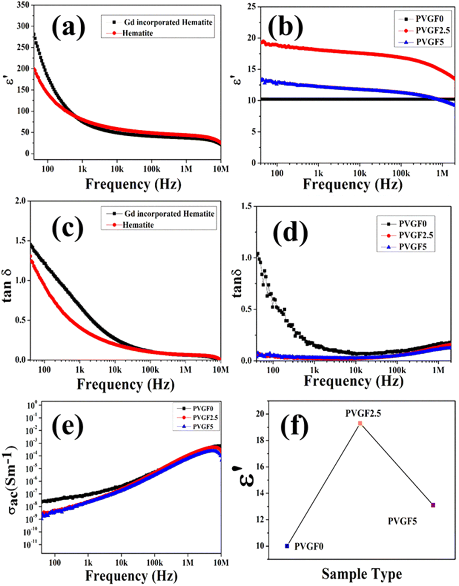 | ||
| Fig. 4 (a) Dielectric constants with frequency for α-hematite and Gd-incorporated α-hematite nanoparticles, suggesting that the incorporation of Gd enhanced the dielectric constant of the NPs. (b) Dielectric constants of PVGF0, PVGF2.5, and PVGF5. (c) and (d) Tangent loss of NPs and membranes, suggesting low energy dissipation. (e) Variation of ac conductivities with frequency for the nanocomposite membranes shows maximum conductivity in PVGF2.5. (f) A comparison of the dielectric constants of samples PVGF0, PVGF2.5, and PVGF5 at 40 Hz. | ||
The dielectric constants of the nanocomposite membranes were also measured. Pieces of the three films (PVGF0, PVGF2.5, PVGF5) of 1 cm2 in size had two aluminium electrodes attached to form a device to measure the electrical properties of the membranes. Graphs of the dielectric constants of the three nanocomposite membranes with frequency are shown in Fig. 4(b). It is noteworthy that the dielectric constant has increased due to doping with Gd-doped hematite NPs. PVGF2.5 shows the highest dielectric value of 19 at 40 Hz and the pristine PVDF membrane has the lowest value of 10 at 40 Hz [Fig. 4(f)]. The polarization increases due to the doping with NPs which also causes an enhancement in dielectric phenomena as well as the β-phase of the PVGF2.5 film.50 It was also noticed that the dielectric constant reduces with an increase in frequency, which is evidence of Maxwell–Wagner polarisation, which explains that with high frequency, the dipole cannot change rapidly causing a reduction in dielectric permittivity.51 Tangent loss and the ac conductivity with varying frequencies were also measured. A doped membrane exhibits lower tangent loss (0.05) than a pure one at a frequency of 40 Hz, as depicted in Fig. 4(d). The very low tangent loss minimizes energy dissipation, which is very advantageous for future use.52 The ac conductivity of the membranes increases with an increase in frequency, as shown in Fig. 4(e). In reality, the conducting grains achieve the required amount of activation energy to become free at higher frequency, enhancing the conductivity in the higher frequency range.53 The dielectric permittivity data suggest that the maximum polarization occurs in PVGF2.5. This result is also analogous to the XRD and FTIR measurements, which showed that the maximum polarization was achieved in the 2.5% nanocomposite doped membrane. These high polarizing properties meant this self-poled free-standing membrane was promising for piezo-responsive applications.
The piezoelectric coefficients (d33) of all the fabricated membranes were also measured to determine the piezo-effectiveness.54 The piezoelectric coefficients of the synthesized membranes were calculated with the following relation:55
 | (4) |
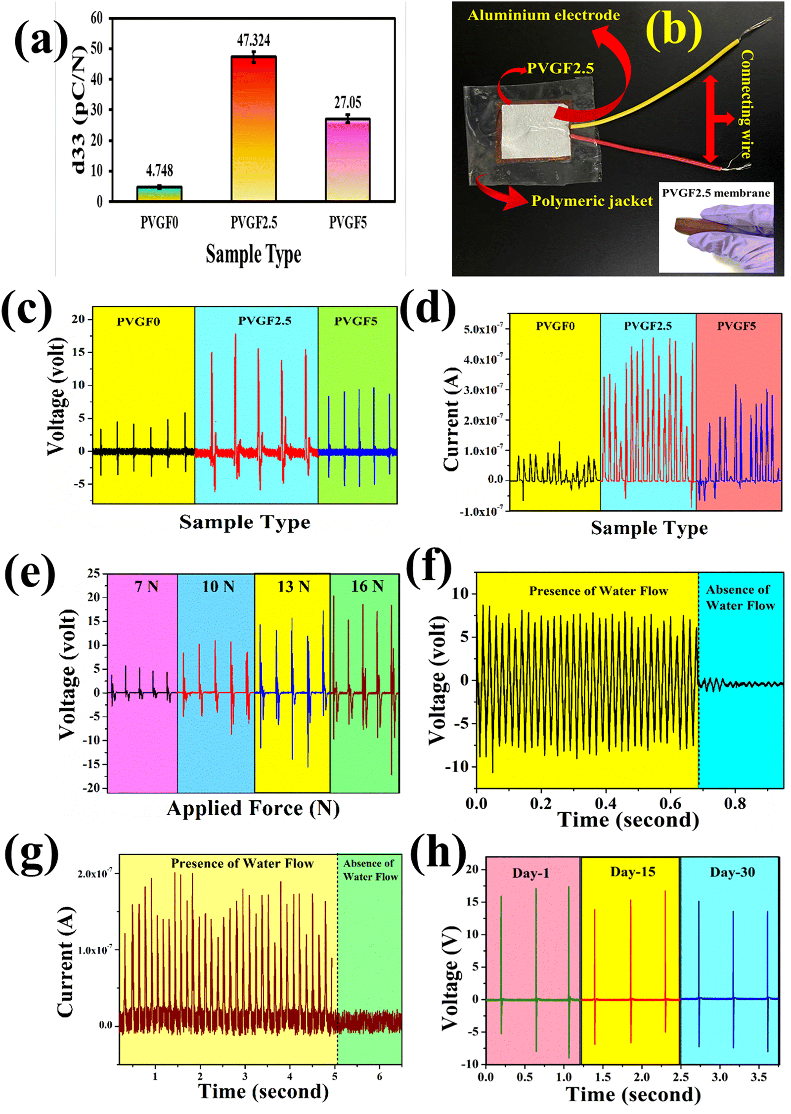 | ||
| Fig. 5 (a) Piezoelectric coefficients of the nanocomposite membranes suggesting that PVGF2.5 possesses the highest d33 value. (b) Real image of the fabricated device and in the inset the fabricated PVGF2.5 nanocomposite membrane. (c) and (d) Open circuit voltage and short circuit current due to finger tapping on PVGF0, PVGF2.5 and PVGF5 devices. (e) Piezoelectric voltage generation under different applied forces. (f) and (g) Open circuit voltage and short circuit current of the PVGF2.5 device under water flow. (h) Performance test of the device over time. | ||
3.3. Piezoelectric energy generation
![[thin space (1/6-em)]](https://www.rsc.org/images/entities/char_2009.gif) :1 passive probe). The short circuit currents were obtained using a Keithley DAQ6510 multi-meter system. The open circuit output voltages were found to be around 6.5, 16.92, and 10.1 V for PVGF0, PVGF2.5, and PVGF5, respectively. The short circuit currents were also recorded and found to be 0.14, 0.52, and 0.32 μA, respectively, due to finger tapping with a tapping force of 13.49 N (S5). Graphs of the instantaneous voltage and current are shown in Fig. 5(c) and (d), respectively. The force-varying open circuit voltages were also measured and it was found that the voltage increases with increasing force on the device [Fig. 5(e)]. The voltages were found to be 5.6 V, 11.07 V, 16.92 V, and 20.44 V at forces of 7, 10, 13, and 16 N, respectively. It was found that under a constant mechanical force, the voltage and current generation are at their maximum in PVGF2.5, which is in good agreement with the experimental evidence from XRD, FTIR, D.C., and d33 measurements. The instantaneous power density was calculated from the following relation:31
:1 passive probe). The short circuit currents were obtained using a Keithley DAQ6510 multi-meter system. The open circuit output voltages were found to be around 6.5, 16.92, and 10.1 V for PVGF0, PVGF2.5, and PVGF5, respectively. The short circuit currents were also recorded and found to be 0.14, 0.52, and 0.32 μA, respectively, due to finger tapping with a tapping force of 13.49 N (S5). Graphs of the instantaneous voltage and current are shown in Fig. 5(c) and (d), respectively. The force-varying open circuit voltages were also measured and it was found that the voltage increases with increasing force on the device [Fig. 5(e)]. The voltages were found to be 5.6 V, 11.07 V, 16.92 V, and 20.44 V at forces of 7, 10, 13, and 16 N, respectively. It was found that under a constant mechanical force, the voltage and current generation are at their maximum in PVGF2.5, which is in good agreement with the experimental evidence from XRD, FTIR, D.C., and d33 measurements. The instantaneous power density was calculated from the following relation:31 | (5) |
Besides finger tapping, the device can also harvest energy from water flow and it was found that the open circuit voltage during the flow of water was 8 V and its graph has been depicted in Fig. 5(f). The corresponding short circuit current due to the flow of water was found to be around 0.2 μA [Fig. 5(g)]. The experimental setup and energy generation by water flow have been depicted in a video in the ESI† Section of this paper S8. Herein, tap water with a TDS (total dissolved solids) value of 162 ppm was taken as the water source and generated the water flow by means of a simple overhead stirrer. A water-quality-dependent study was illustrated in recent work from our group. Basically, the TDS of water plays a pivotal role in water-flow-based energy generation. Water with more TDS applied more force on the device because of the solids dissolved in it and the voltage was also enhanced.59
| S. no. | Type of mechanical force | Material | Output voltage | d 33 | Ref. | ||
|---|---|---|---|---|---|---|---|
| 1 | Applying stress – 500 N | Cu-BZT-BCT/PVDF | 20.61 V | 600 pC/N | 65 | ||
| 2 | Finger tapping | Water tapping | Bilayered pBT@CNF/PVDF-g-MA nanofibrous membranes | 1.2 V | 2 V | 27.2 pC/N | 66 |
| 3 | Finger tapping | BaTiO3/poly(vinylidene fluoride–trifluoroethylene) | 0.6 V | 67 | |||
| 4 | Repetitive finger tapping | Stretchable polymer-modulated PVDF-HFP/TiO2 nanoparticles | 9.7 V | 68 | |||
| 5 | Repetitive tapping | Water flow | P(VDF-TrFE) nanofibers with BaSrTiO3 nanoparticles (NF-PENG composed of ES-3BST20PNF) | 7.5 V | 0.10 V | 57.6 pm V−1 | 69 |
| 6 | Finger tapping | GaFeO3–PVDF composites | 3 V | 70 | |||
| 7 | Bending | BaTiO3/P(VDF-TrFE) | 0.45 V | 40 pm V−1 | 71 | ||
| 8 | Ball dropping | CNT-PVDF | 0.9 V | 72 | |||
| 9 | Finger tapping | Water flow | Gd-incorporated hematite decorated PVDF membrane | 16.92 V | 8 V | 47.32 pC/N | This work |
4. Conclusions
This article reports the successful synthesis procedure of Gd-incorporated natural hematite in nano form and also the incorporation of these nanoparticles into a polymeric matrix to fabricate flexible membranes. The incorporation of a rare earth element (Gd3+) into the α-Fe2O3 structure greatly influences the microstrain, which ultimately enhances the polarisability. Moreover, doping of the Gd-loaded hematite in the PVDF-HFP matrix enhances the β-phase of the film, as established from the FTIR, dielectric, and d33 studies. The nanoparticle loading also improves the stability of the membrane, making it suitable for commercial use. A solid-state device fabricated from the flexible membrane is capable of generating piezoelectric energy from finger tapping as well as water flow. It is recorded that the voltage generated due to finger tapping is 16.92 V and the current is 0.52 μA and hence the power density is 232.38 μW cm−3. Another interesting finding of this article is that the device reported herein can also harvest piezoelectric energy from water flow like a non-invasive stimulus. Thus, a reusable, robust, free-standing, cost-effective device can be useful for harvesting energy from naturally flowing water sources, cutting down dependency on conventional energy sources. From the flow of water, it has generated a voltage of 8 V and a current of 0.2 μA which are quite high and thus it could be a sustainable and futuristic solution to eliminate the energy crisis for growing industrialization and modernization.Data availability
Data and codes will be available on reasonable request.Author contributions
Saheli Ghosh: data curation, conceptualization, computation, writing – original draft. Dhananjoy Mondal: data curation, investigation. Jhilik Roy: data curation. Souravi Bardhan: data curation, writing – assistance. Shubham Roy: conceptualization, computation, writing – editing. Ayan Mazumdar: data curation, computation. Neelanjana Bag: data curation. Ruma Basu: supervision. Sukhen Das: supervision, funding acquisition.Conflicts of interest
The authors declare that they have no competing interests.Acknowledgements
The authors would like to thank the Department of Physics, Jadavpur University, for extending experimental facilities. S. D. and D. M. would like to acknowledge UGC-DAE-CSR (Grant No. CRS/2021-22/02/498), and J. R. and R. B acknowledge UGC-DAE-CSR (Grant No. CRS/2021-22/02/514) for funding.References
- B. Chapman, Understanding the Global Energy Crisis, 2014, 27–72.
- R. Poudyal, P. Loskot, R. Nepal, R. Parajuli and S. K. Khadka, Renewable Sustainable Energy Rev., 2019, 116, 109388 CrossRef.
- B. Mufutau Opeyemi, Energy, 2021, 228, 120519 CrossRef.
- J. Rogelj, P. M. Forster, E. Kriegler, C. J. Smith and R. Séférian, Nature, 2019, 571, 335–342 CrossRef CAS.
- X. Zheng, D. Streimikiene, T. Balezentis, A. Mardani, F. Cavallaro and H. Liao, J. Cleaner Prod., 2019, 234, 1113–1133 CrossRef.
- T. Molla, B. Khan, B. Moges, H. H. Alhelou, R. Zamani and P. Siano, CSEE J. Power Energy Syst., 2019, 5(2), 249–258 Search PubMed.
- N. Sezer and M. Koç, Nano Energy, 2021, 80, 105567 CrossRef CAS.
- A. Kasaeian, A. Razmjoo, R. Shirmohammadi, F. Pourfayaz and A. Sumper, Environ. Prog. Sustain. Energy, 2020, 39, e13354 CrossRef CAS.
- A. G. Olabi, M. Mahmoud, B. Soudan, T. Wilberforce and M. Ramadan, Renew Energy, 2020, 147, 2003–2012 CrossRef.
- A. Qazi, F. Hussain, N. A. B. D. Rahim, G. Hardaker, D. Alghazzawi, K. Shaban and K. Haruna, IEEE Access, 2019, 7, 63837–63851 Search PubMed.
- O. Guselnikova, R. Elashnikov, P. Postnikov, V. Svorcik and O. Lyutakov, ACS Appl. Mater. Interfaces, 2018, 10, 37461–37469 CrossRef CAS PubMed.
- A. Mhasde, S. Sutar, N. Tamboli, S. Randive, J. Athalye and K. Ghorpade, Int. J. Res. Eng. Sci., 2021, 9(12), 98–101 Search PubMed.
- S. K. Karan, S. Maiti, J. H. Lee, Y. K. Mishra, B. B. Khatua and J. K. Kim, Adv. Funct. Mater., 2020, 30, 2004446 CrossRef CAS.
- S. M. H. Qaid, B. A. Al-Asbahi, H. M. Ghaithan, M. S. AlSalhi and A. S. Al Dwayyan, J. Colloid Interface Sci., 2020, 563, 426–434 CrossRef CAS PubMed.
- Z. Zhang, Y. Nan, Y. K. Mishra, M. Willatzen and Z. L. Wang, Appl. Phys. Lett., 2023, 123(2), 023501 CrossRef CAS.
- N. Parvin, V. Kumar, A. Manikkavel, S. S. Park, T. Kumar Mandal and S. Woo Joo, Appl. Surf. Sci., 2023, 613, 156078 CrossRef CAS.
- S. Ghosh, S. Roy, S. Bardhan, N. Khatua, B. Bhowal, D. K. Chanda, S. Das, D. Mondal, R. Basu and S. Das, J. Electron. Mater., 2021, 50, 3836–3845 CrossRef CAS.
- D. Nath, F. Singh and R. Das, Mater. Chem. Phys., 2020, 239, 122021 CrossRef CAS.
- S. Dagar, A. Hooda, S. Khasa and M. Malik, J. Alloys Compd., 2019, 806, 737–752 CrossRef CAS.
- H. Asai, Y. Terada and K. Nakane, Polymer, 2022, 244, 124650 CrossRef CAS.
- Z. Li, D. Liu, Y. Cai, Y. Wang and J. Teng, Fuel, 2019, 257, 116031 CrossRef CAS.
- R. F. Egerton, Micron, 2019, 119, 72–87 CrossRef CAS.
- F. El Kalai, E. B. Çınar, C. H. Lai, S. Daoui, T. Chelfi, M. Allali, N. Dege, K. Karrouchi and N. Benchat, J. Mol. Struct., 2021, 1228, 129435 CrossRef PubMed.
- A. Ali, Y. W. Chiang and R. M. Santos, Minerals, 2022, 12, 205 CrossRef CAS.
- L. Yang, G. Xiao, D. Ding, B. Chen, J.-X. Wang, D. Wang, S. Roy, S. Bardhan, D. K. Chanda, A. Maity, S. Ghosh, D. Mondal, S. Singh and S. Das, Mater. Res. Express, 2020, 7, 025020 CrossRef.
- P. Raizada, V. Soni, A. Kumar, P. Singh, A. A. Parwaz Khan, A. M. Asiri, V. K. Thakur and V. H. Nguyen, J. Materiomics, 2021, 7, 388–418 CrossRef.
- S. Roy, K. Pal, S. Bardhan, S. Maity, D. K. Chanda, S. Ghosh, P. Karmakar and S. Das, Inorg. Chem., 2019, 58, 8369–8378 CrossRef CAS PubMed.
- A. Das, R. R. Wary and R. G. Nair, Solid State Sci., 2020, 104, 106290 CrossRef CAS.
- P. Saha, T. Debnath, S. Das, S. Chatterjee and S. Sutradhar, Mater. Sci. Eng., B, 2019, 245, 17–29 CrossRef CAS.
- J. Singh, S. Sharma, S. Soni, S. Sharma and R. Chand Singh, Mater. Sci. Semicond. Process., 2019, 98, 29–38 CrossRef CAS.
- D. Mondal, S. Bardhan, N. Das, J. Roy, S. Ghosh, A. Maity, S. Roy, R. Basu and S. Das, Nano Energy, 2022, 104, 107893 CrossRef CAS.
- H. Chai, L. Gao and J. Jin, ChemSusChem, 2022, 15, e202201030 CrossRef CAS.
- H. Kahil, A. Faramawy, H. El-Sayed and A. Abdel-Sattar, Crystals, 2021, 11, 1153 CrossRef CAS.
- G. Midekessa, K. Godakumara, J. Ord, J. Viil, F. Lättekivi, K. Dissanayake, S. Kopanchuk, A. Rinken, A. Andronowska, S. Bhattacharjee, T. Rinken and A. Fazeli, ACS Omega, 2020, 5, 16701–16710 CrossRef CAS PubMed.
- K. Pan, C. Yang, J. Hu, W. Yang, B. Liu, J. Yang, S. Liang, K. Xiao and H. Hou, J. Hazard. Mater., 2020, 389, 122072 CrossRef CAS PubMed.
- A. Ahmed, Y. Jia, H. Deb, M. F. Arain, H. Memon, K. Pasha, Y. Huang, Q. Fan and J. Shao, J. Mater. Sci.: Mater. Electron., 2022, 33, 3965–3981 CrossRef CAS.
- Y. Fu, Y. Cheng, C. Chen, D. Li and W. Zhang, Polym. Test., 2022, 108, 107513 CrossRef CAS.
- S. Ghosh, S. Bardhan, D. Mondal, D. Sarkar, J. Roy, S. Roy, R. Basu and S. Das, Ceram. Int., 2023, 49, 14710–14718 CrossRef CAS.
- A. H. Asghar, S. Abbas, A. Qaseem, T. Kokab, A. Tajammul, A. Ramzan, S. Saeed and U. Iqbal, Proceedings of 18th International Bhurban Conference on Applied Sciences and Technologies, IBCAST 2021, 2021, 55–66.
- D. Díez, A. Urueña, R. Piñero, A. Barrio and T. Tamminen, Processes, 2020, 8, 1048 CrossRef.
- A. M. AlAhzm, M. O. Alejli, D. Ponnamma, Y. Elgawady and M. A. A. Al-Maadeed, J. Mater. Sci.: Mater. Electron., 2021, 32, 14610–14622 CrossRef CAS.
- P. C. Irwin, Y. Cao, A. Bansal and L. S. Schadler, Conference on Electrical Insulation and Dielectric Phenomena (CEIDP), Annual Report, 2003, 120–123.
- G. Moradi, S. Zinadini and M. Rahimi, J. Environ. Chem. Eng., 2023, 11, 109952 CrossRef CAS.
- J. M. Hadi, S. B. Aziz, M. S. Mustafa, M. H. Hamsan, R. T. Abdulwahid, M. F. Z. Kadir and H. O. Ghareeb, J. Mater. Res. Technol., 2020, 9, 9283–9294 CrossRef CAS.
- P. Priyadarshini, S. Senapati, S. Bisoyi, S. Samal and R. Naik, J. Alloys Compd., 2023, 945, 169222 CrossRef CAS.
- M. Junaid, M. A. Khan, M. N. Akhtar, A. Hussain and M. F. Warsi, Ceram. Int., 2019, 45, 13431–13437 CrossRef CAS.
- C. Li, G. Chen, X. Qiu, Q. Lou and X. Gao, AIP Adv., 2021, 11, 65227 CrossRef CAS.
- P. Sivaprakash, S. Divya, R. Parameshwari, C. Saravanan, S. Sagadevan, S. Arumugam and S. Esakki Muthu, J. Mater. Sci.: Mater. Electron., 2020, 31, 16369–16378 CrossRef CAS.
- Q. Raza, I. Bibi, F. Majid, S. Kamal, S. Ata, A. Ghafoor, M. I. Arshad, S. H. Al-Mijalli, A. Nazir and M. Iqbal, J. Ind. Eng. Chem., 2023, 118, 469–482 CrossRef CAS.
- M. Kushwah, R. Sagar, A. A. Rogachev and M. S. Gaur, Vacuum, 2019, 166, 298–306 CrossRef CAS.
- B. Sharmila, N. George, S. Sasi, J. V. Antony, J. Chandra, V. Raman and D. Nambath Purushothaman, Polym. Adv. Technol., 2022, 33, 3151–3162 CrossRef.
- M. T. Sebastian, R. Ubic and H. Jantunen, Int. Mater. Rev., 2015, 60, 392–412 CrossRef.
- T. Defferriere, D. Klotz, J. C. Gonzalez-Rosillo, J. L. M. Rupp and H. L. Tuller, Nat. Mater., 2022, 21, 438–444 CrossRef CAS PubMed.
- C. Miclea, A. Asoiu, L. Amarande, C. F. Miclea, C. PlAvitu, A. Avitu, M. Cioangher, L. Trupina, C. T. Miclea and C. David, Rom. J. Inf. Sci. Technol., 2007, 10, 243–250 Search PubMed.
- N. Das, D. Sarkar, M. M. Saikh, P. Biswas, S. Das, N. A. Hoque and P. P. Ray, Nano Energy, 2022, 102, 107628 CrossRef CAS.
- N. Sezer and M. Koç, Nano Energy, 2021, 80, 105567 CrossRef CAS.
- Q. Zhu, T. Wu and N. Wang, Biosensors, 2023, 13, 113 CrossRef CAS PubMed.
- Z. Y. Shen and J. F. Li, J. Ceram. Soc. Jpn., 2010, 118, 940–943 CrossRef CAS.
- D. Mondal, S. Bardhan, N. Das, J. Roy, S. Ghosh, A. Maity, S. Roy, R. Basu and S. Das, Nano Energy, 2022, 104, 107893 CrossRef CAS.
- S. K. Si, S. Paria, S. K. Karan, S. Ojha, A. K. Das, A. Maitra, A. Bera, L. Halder, A. De and B. B. Khatua, Nanoscale, 2020, 12, 7214–7230 RSC.
- A. Gebrekrstos, T. S. Muzata and S. S. Ray, ACS Appl. Nano Mater., 2022, 5, 7632–7651 CrossRef CAS.
- M. B. Starr, J. Shi and X. Wang, Angew. Chem., 2012, 124, 6064–6068 CrossRef.
- D. Sarkar, N. Das, M. M. Saikh, P. Biswas, S. Das, S. Das, N. A. Hoque and R. Basu, ACS Omega, 2021, 6, 28710–28717 CrossRef CAS PubMed.
- R. Caliò, U. B. Rongala, D. Camboni, M. Milazzo, C. Stefanini, G. de Petris and C. M. Oddo, Sensors, 2014, 14, 4755–4790 CrossRef PubMed.
- D. J. Shin, J. H. Ji, J. Kim, G. H. Jo, S. J. Jeong and J. H. Koh, J. Alloys Compd., 2019, 802, 562–572 CrossRef CAS.
- L. Wang, T. Cheng, W. Lian, M. Zhang, B. Lu, B. Dong, K. Tan, C. Liu and C. Shen, Carbohydr. Polym., 2022, 275, 118740 CrossRef CAS PubMed.
- J. Nunes-Pereira, V. Sencadas, V. Correia, V. F. Cardoso, W. Han, J. G. Rocha and S. Lanceros-Méndez, Composites, Part B, 2015, 72, 130–136 CrossRef CAS.
- R. Mitra, B. Sheetal Priyadarshini, A. Ramadoss and U. Manju, Mater. Sci. Eng., B, 2022, 286, 116029 CrossRef CAS.
- S. An, H. S. Jo, G. Li, E. Samuel, S. S. Yoon and A. L. Yarin, Adv. Funct. Mater., 2020, 30, 2001150 CrossRef CAS.
- M. Mishra, A. Roy, S. Dash and S. Mukherjee, IOP Conf. Ser.: Mater. Sci. Eng., 2018, 338, 012026 Search PubMed.
- F. Wang, Y. W. Mai, D. Wang, R. Ding and W. Shi, Sens. Actuators, A, 2015, 233, 195–201 CrossRef CAS.
- F. Mokhtari, M. Shamshirsaz, M. Latifi and S. Asadi, J. Text. Inst., 2016, 108, 906–914 CrossRef.
Footnote |
| † Electronic supplementary information (ESI) available. See DOI: https://doi.org/10.1039/d3tc01920a |
| This journal is © The Royal Society of Chemistry 2023 |