
Strategies to improve the photocatalytic performance of covalent triazine frameworks
Yubing
Liu†
a,
Hao
Wu†
a and
Qian
Wang
 *ab
*ab
aGraduate School of Engineering, Nagoya University, Furo-cho, Chikusa-ku, Nagoya 464-8603, Japan. E-mail: wang.qian@material.nagoya-u.ac.jp; Tel: +81-527893250
bInstitute for Advanced Research, Nagoya University, Furo-cho, Chikusa-ku, Nagoya 464-8601, Japan
First published on 19th September 2023
Abstract
Covalent triazine frameworks (CTFs) have emerged as a prominent group of organic semiconductors, distinguishing themselves from covalent organic frameworks (COFs) for their applications in photocatalysis. Their unique features, such as a fully conjugated structure, triazine unit, interlayer π–π interaction, large specific surface area, and exceptional thermal and chemical stability, make them promising candidates for artificial photosynthetic processes, including photocatalytic water splitting and CO2 reduction reactions. However, challenges like high exciton binding energy and carrier recombination need to be addressed. In this review, we highlight the latest advances in utilizing CTFs for photocatalytic applications and delve into strategies aimed at modifying the band structure, enhancing photoexcited carrier separation, and improving carrier transfer processes in CTFs. These approaches involve molecular design, structural regulation, and the creation of heterostructures, all aimed at boosting the quantum efficiency of photocatalytic reactions. These efforts hold tremendous potential for advancing solar fuel production.
 Yubing Liu | Yubing Liu received his PhD degree from the School of Chemistry and Chemical Engineering at Nanjing University in 2016. He then continued as a postdoctoral fellow at the School of Environment at Nanjing University. Currently, he joined the research group of Professor Qian Wang at Nagoya University as a visiting scholar. His research interests mainly focus on the design and construction of covalent organic framework materials and their applications in photocatalysis. |
 Hao Wu | Hao Wu is pursuing his PhD degree under the supervision of Prof. Qian Wang at Nagoya University, Japan. He received his Bachelor's degree in 2019 and Master's degree in 2022 from Beijing University of Chemical Technology, China. His current research interests focus on the design of artificial photosynthesis devices for CO2 reduction. |
 Qian Wang | Qian Wang is currently an Associate Professor at Nagoya University, Japan. She obtained her PhD in 2014 at the University of Tokyo, Japan and subsequently conducted postdoctoral research at the same institution. In 2018, she became a Marie Sklodowska-Curie Research Fellow at the University of Cambridge. She joined Nagoya University as an Associate Professor in May 2021 and established her research group, which is currently developing new materials, approaches, and technologies for solar energy storage in the form of renewable fuels via artificial photosynthesis. |
1. Introduction
As one of the most popular star materials in recent years, covalent organic framework materials (COFs)1,2 have been intensively studied in various fields including photocatalysis,3,4 electrocatalysis,5 drug delivery,6 heterogeneous catalysis,7,8 batteries9 and environmental applications.10,11 Covalent triazine framework materials (CTFs)12 are a type of covalent organic framework material that are generally constructed by connecting different monomers with triazine rings as linking groups (Fig. 1). CTFs, as ordered crystalline organic semiconductor materials, exhibit the following characteristics: (1) rich N content. The triazine structure as a connecting group greatly increases the N content of CTFs. This high N content contributes to the heteroatom effect, resulting in abundant active and functional centers for catalytic reactions.13,14 Moreover, the N-rich structure enables CTFs to exhibit certain basic and electron donor properties.15,16 (2) Ordered conjugated structure.14 The ordered arrangement of triazine rings and functionalized monomers in the structure of CTFs forms a highly conjugated structure. This ordered conjugation of crystalline states can facilitate the transport of non-equilibrium carriers in the excited state and reduce the chance of charge recombination. (3) Large specific surface area.17 The ordered in-plane arrangement of monomers in the CTF structure and the ordered stacking between layers lead to the formation of regular pore channels. This unique structure contributes to a large specific surface area, providing a significant number of active sites for catalytic reactions. (4) Diverse monomer selection.18 The diverse range of organic monomers used in the construction of CTFs allows for easy modulation of the optoelectronic properties of the synthesized CTF materials by altering the monomer composition. This tunability of properties makes CTFs highly promising for applications in the field of photocatalysis.19–23 (5) High thermal and chemical stability due to C![[double bond, length as m-dash]](https://www.rsc.org/images/entities/char_e001.gif) N in the triazine structure.24
N in the triazine structure.24
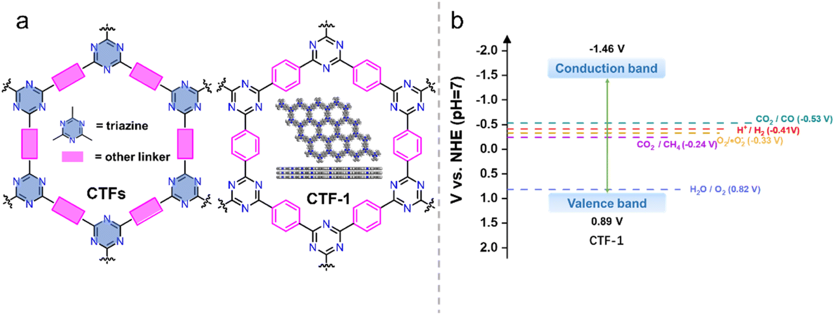 | ||
| Fig. 1 (a) The structures of CTF and CTF-1. (b) Energy diagram of CTF-1 (ref. 25) (t-BuOK-assisted synthesis). | ||
Due to the growing scarcity of energy resources and the environmental impact associated with the extensive use of fossil fuels, there is an urgent need to explore and develop alternative clean energy sources. Converting and storing solar energy into chemical energy via artificial photosynthetic processes, such as photocatalysis, offers a promising approach to alleviate the reliance on fossil fuels while simultaneously reducing greenhouse gas emissions. These processes involve using solar energy to drive the water-splitting reaction that produces green hydrogen (H2) from water and convert CO2 into high-value carbon-based chemicals and fuels (C1 to C4 species).26–28
Since the groundbreaking work by Fujishima and Honda on water splitting over TiO2 photoelectrodes under UV light irradiation,29 the field of photocatalyst research has experienced rapid development. Efficient photocatalysts are characterized by several key factors, including (1) a narrow bandgap to ensure effective utilization of solar energy; (2) suitable conduction and valence band positions to drive desired oxidation and reduction reactions involved in processes like proton/CO2 reduction and water oxidation; (3) good stability during the photocatalytic reaction; (4) low cost; (5) good recyclability; and (6) practicality and feasibility for commercial-scale applications.
CTFs have demonstrated great potential in terms of controllable energy band structures, photocatalytic performance, stability, and cost-effectiveness. However, unmodified CTFs still face challenges, including low utilization of visible light, high recombination probability of photogenerated carriers, and tight stacking that hinders the exposure of active sites.13,30 In this review, we investigate the recent advancements in the utilization of CTFs for photocatalytic applications, specifically in the areas of water splitting, CO2 reduction, and organic transformations. We also outline emerging techniques that have been employed to enhance the photocatalytic performance of CTFs, including molecular design, structural regulation, and heterostructure engineering (Fig. 2). Throughout the review, we not only highlight the significant findings and achievements in this field but also identify the remaining challenges ahead, aiming to provide valuable insights and guidance for the development of new and highly efficient photocatalytic systems based on CTFs.
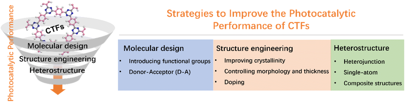 | ||
| Fig. 2 The strategies to improve the photocatalytic performance of CTFs. | ||
2. CTFs for photocatalytic applications
Photocatalytic reactions (Fig. 3) involve three key steps:27 (1) photon absorption: photocatalysis begins with photons being absorbed, elevating electrons from the valence band (VB) to the conduction band (CB) and generating electron–hole pairs (e−/h+). (2) Charge separation and migration: excited electrons and holes move within the photocatalyst material, concentrating at active surface sites for subsequent reactions. (3) Redox reactions: accumulated electron–hole pairs initiate redox reactions facilitated by cocatalysts. Electrons participate in reduction reactions, while holes engage in oxidation reactions. Thus, the CB minimum must be more negative than the reduction potential, and the VB maximum must be more positive than the oxidation potential.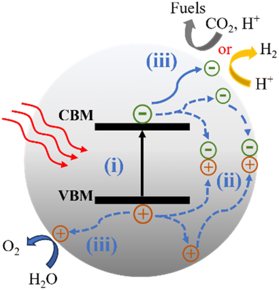 | ||
| Fig. 3 Scheme of the photocatalytic CO2 reduction reaction and water splitting for the semiconductor. CBM: conduction-band minimum; VBM: valence-band maximum. (i) Absorption of photons. (ii) Charge separation, migration and recombination. (iii) Surface reactions. | ||
To achieve specific photocatalytic reactions, for example, water splitting, an energy requirement (ΔE) of 1.23 V is necessary to decompose one molecule into H2 and 1/2 O2, corresponding to a change in Gibbs free energy of 237.2 kJ mol−1. Consequently, the photocatalyst must possess a bandgap wider than 1.23 V. In practice, a bandgap greater than 1.6 eV is often desired to fulfill additional kinetic requirements.31 CO2 is known to be a thermodynamically stable and chemically inert molecule, making the breaking of the CO bond a highly energy-demanding process.32 Photocatalytic CO2 reduction is a complex process that produces various reduction products including gaseous products (CO, CH4, etc.) and liquid products (CH3OH, CHOOH, etc.)33 through single or multiple electron transfer processes.
CTFs are well suited for photocatalytic hydrogen production reactions in terms of the energy band structure. As an example, CTF-1 (Fig. 1), the most representative CTF, has a bandgap of about 2.35 eV.25 The valence and conduction band positions (Fig. 1b) are suitable for enabling both hydrogen and oxygen evolution. Additionally, the energy band structure of CTF-1 can finely be tailored by employing different synthesis methods and selecting different monomeric raw materials, linkage groups, and functional groups,34 adjusting the crystallinity of the material,35 or introducing donor–acceptor (D–A)36 structures. These strategies provide opportunities to optimize the energy band alignment to suit a specific photocatalytic reaction. Furthermore, the inherent basicity of CTFs37,38 and the incorporation of basic functional groups can enhance the adsorption of CO2 and promote the activation of CO2 molecules in the photocatalytic CO2 reduction reaction,39 which contribute to enhanced conversion efficiency of CO2, making CTFs promising materials for efficient photocatalytic CO2 reduction.
In the design of photocatalysts, it is desirable for the catalyst to have a wide absorption range, as approximately 43% of the energy in solar radiation falls within the visible range (400–700 nm).27 In the structure of CTFs, π-conjugated units play a crucial role in light absorption, where visible light allows electrons to undergo the π → π* transition.40 To enhance the absorption range of CTFs and improve their photocatalytic performance, specific groups are often introduced from a structural design perspective.
In addition to the stringent thermodynamic requirements, photocatalytic reactions also face kinetic challenges. The timescales for charge separation, migration of photogenerated carriers, and surface reactions can range from picoseconds (ps) to milliseconds (ms).41,42 Achieving efficient solar energy conversion requires effective synergy between each step. The crystal structure, crystallinity, and particle size of the photocatalyst significantly influence charge separation and migration of photogenerated carriers. CTFs exhibiting poor crystallinity are often associated with a high density of structural defects. These defects typically function as sites for the capture and recombination of photogenerated electrons and holes, resulting in a reduction in quantum efficiency and consequently low photocatalytic activity.43 Conversely, a higher crystal quality promotes efficient charge separation and reduces carrier recombination, enhancing the overall quantum efficiency and photocatalytic performance. Controlling the particle size is another crucial factor in optimizing photocatalytic activity. Smaller particle sizes result in a shorter distance between the photogenerated electrons and holes, facilitating their migration to the surface reaction sites.44 This reduced distance can also reduce the probability of carrier recombination, thereby enhancing photocatalytic efficiency. In the case of CTFs, their π–π layered stacking structure and relatively fewer layers favor the transport of photogenerated carriers from the bulk phase to the surface through interlayer migration.13 To further improve the separation and migration efficiency of photogenerated carriers, related studies have focused on strategies such as increasing crystallinity, introducing D–A structures, and exfoliating CTFs into oligomeric or monolayer.
The last step of surface chemistry involves the presence of active sites on the photocatalyst surface. Even if photogenerated electrons and holes possess thermodynamically sufficient redox potentials, they will recombine with each other if there are no active sites available for redox reactions on the surface. In the H2 evolution reaction (HER), Pt is commonly used as a cocatalyst. Pt not only promotes charge separation and transport but also acts as a reaction site to catalyze the HER. However, Pt can also facilitate the oxygen reduction reactions, which is the reverse reaction of water splitting. This makes Pt unideal for use in overall water splitting (OWS) processes.45 To address this, materials such as Ru or Rh have been widely utilized as alternatives to Pt in promoting the OWS reaction.46 For the CO2 reduction reaction (CO2RR), metal–organic complexes are often employed as cocatalysts to provide active centers.32 The structural diversity and modifiability of CTFs can offer a rich variety of active sites, while their high specific surface area and regular pore structure facilitate the construction of numerous active sites with well-defined structures. This property of CTFs allows for the exploration of various active site structures and their correlation with photocatalytic performance, serving as research models for improving the photocatalytic performance and elucidating the relationships between active site structures and overall photocatalytic efficiency.
3. Strategies for improving the photocatalytic activity of CTFs
3.1 Molecular design
| Functional groups | Photocatalyst | Reaction | Reactants | Light source | Production | Ref. |
|---|---|---|---|---|---|---|
| a TEOA: triethanolamine. b AA: ascorbic acid. c AQY: apparent quantum yield. d EQE: external quantum efficiency. | ||||||
| Nx | 5 mg N3-COF 0.68 wt% Pt | HER | H2O + TEOAa | 300 W Xe lamp (900 > λ > 420 nm) | 1703 μmol h−1 g−1 AQYc = 0.44% | 54 |
| Pyrene | 50 mg CTF-Py 3 wt% Pt | HER | H2O + TEOA | 300 W Xe lamp (λ > 420 nm) | 3080 μmol h−1 g−1 | 55 |
| Thiazolo[5,4-d]thiazole | 10 mg CTF-NWU-1 3 wt% Pt | HER | H2O + TEOA | 300 W Xe lamp (λ > 420 nm) | 17![[thin space (1/6-em)]](https://www.rsc.org/images/entities/char_2009.gif) 600 μmol h−1 g−1 AQY = 0.2% at 420 nm 600 μmol h−1 g−1 AQY = 0.2% at 420 nm |
56 |
| Thiophene | 30 mg ThPy-CPP 10 mL 1-methyl-2-pyrrolidinone | HER | H2O + TEOA | 300 W Xe lamp (λ > 420 nm) | 16690 μmol h−1 g−1 AQY = 4.59% at 420 nm |
36 |
| Thiophene | 20 mg CMP-1 3 wt% Pt | HER | H2O + TEOA | 300 W Xe lamp (λ > 420 nm) | 9698.53 μmol h−1 g−1 AQY = 1.57% at 420 nm | 57 |
| Sulfone | 5 mg FS-COF ≈ 4 wt% Pt | HER | H2O + AAb | 300 W Xe lamp (λ > 420 nm) | 16300 μmol h−1 g−1 EQEd = 3.2% at 420 nm |
61 |
| Thiophene and furan | 10 mg CTF-7 1 wt% Pd | HER | H2O + TEOA | Visible light irradiation (λ > 420 nm) | 7430 μmol h−1 g−1 | 63 |
| –CC– |
50 mg g–C18N3–COF 3 wt% Pt | HER | H2O + AA | Visible light irradiation | 292 μmol h−1 g−1 AQY = 1.06% at 420 nm | 68 |
| Pyrene | 10 mg CTF-Py 5 μmol Co(II) bipyridine complexes | CO2RR | H2O + TEOA | 300 W Xe lamp (λ > 420 nm) | CO selectivity: 95.4% 1373 μmol h−1 g−1 | 55 |
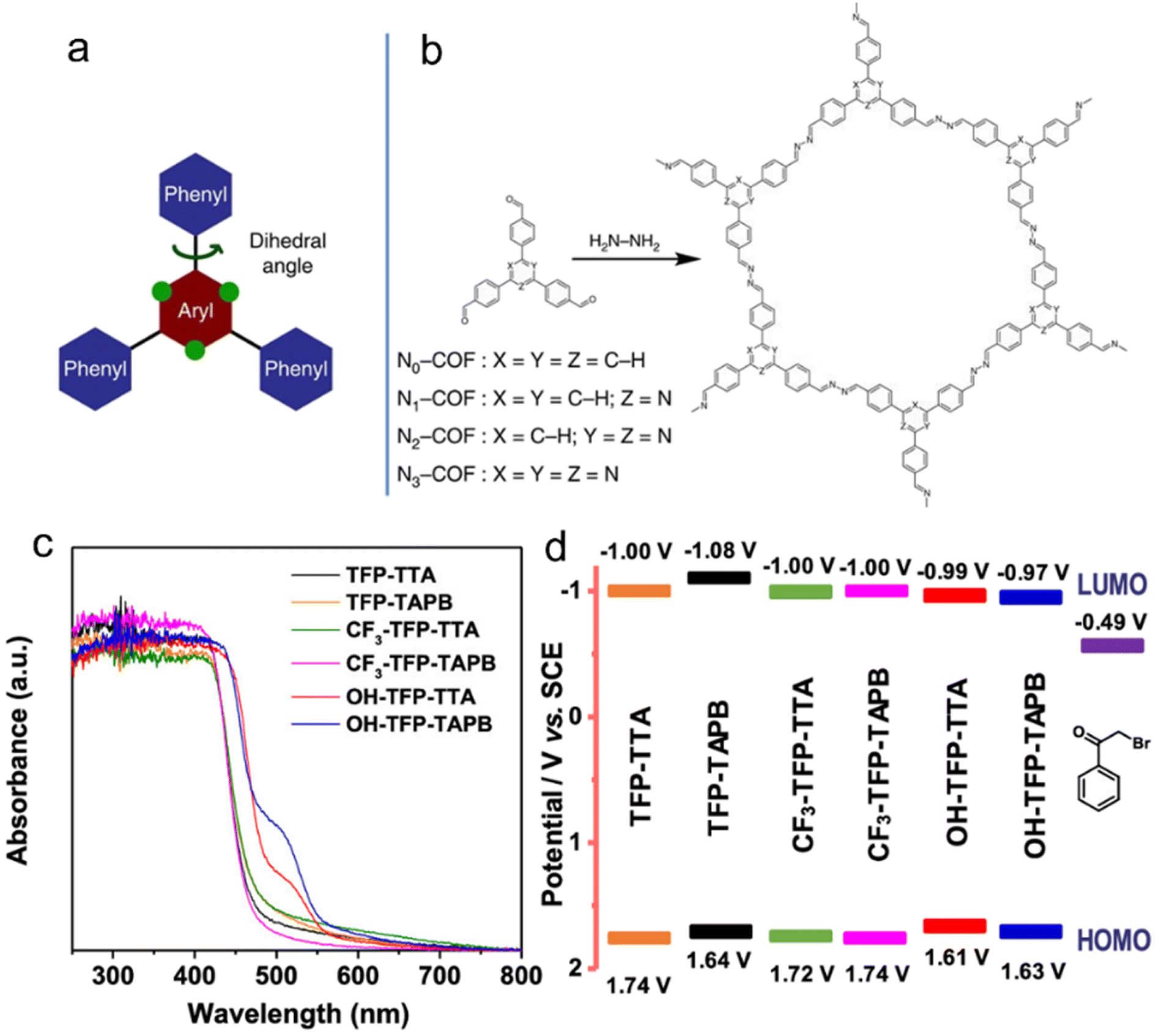 | ||
| Fig. 4 (a) The design of a tunable triphenylarene platform for photocatalytic hydrogen evolution under visible light irradiation by using TEOA as a sacrificial agent. ‘N atoms’ replace ‘C–H’ at the green dots and change the angle between the central aryl and peripheral phenyl rings, leading to varied planarity in the platform. (b) Synthesis of Nx-COFs from Nx-aldehydes and hydrazine. Reproduced with permission from ref. 54. Copyright 2015, Springer Nature. (c) UV-vis spectra, (d) Schematic energy band structures (vs. SCE, with reference to the redox potential of 2-bromoacetophenone) of COFs with –OH, –H and –CF3 substituents. Reproduced with permission from ref. 49. Copyright 2020, American Chemical Society. | ||
Van Speybroeck et al.48 conducted a study combining experimental and theoretical calculations to investigate the modulation of the large π-system and π-electron defects in CTFs in order to broaden the absorption range of the spectrum. Their findings revealed that incorporating aromatic rings, increasing the nitrogen content, or terminating the linker with electron-withdrawing –CN groups were effective strategies for enhancing the absorption capability. In the photocatalytic reductive dehalogenation reactions,49 the introduction of –OH substituents into the aromatic ring of CTFs resulted in a narrower bandgap compared to –H and –CF3 substituents, thereby enhancing the photocatalytic activity under a green light-emitting diode (LED) lamp (30 W, 520–530 nm) (Fig. 4c and d).
Other studies focused on enhancing the transfer of photogenerated electrons by incorporating phenanthroline50 and bipyridine units51,52 into the CTF backbone through precise control of the N-site positions at the atomic level. For instance, the incorporation of phenazoline units in the conjugated Phen-CTF demonstrated improved photoluminescence and strong photoredox properties. In photocatalytic reactions involving activated carbon–halogen bonds (C–Br and C–Cl), such as dehalogenation processes, the presence of CTFs facilitated the formation of C–C, C–P, and C–B bonds through radical trapping under light illumination. Furthermore, investigations into the photocatalytic HER and OWS of various bipyridine-based COFs51–53 revealed that even slight variations in the N sites within COFs can lead to significant differences in electron transfer and band structures.
Jin's group designed and synthesized CTFs based on pyrene (Py)55 and thiazolo[5,4-d]thiazole (TzTz).56 The introduction of pyrene, a well-known fluorescent group, into CTF-PY resulted in high activity in the photocatalytic HER and CO2RR in the presence of triethanolamine (TEOA) as an electron donor under visible light irradiation (λ > 420 nm). On the other hand, the TzTz moieties in CTF-NWU-1 exhibited excellent light absorption properties and strong electron acceptor characteristics, leading to a narrower bandgap and enhanced charge separation ability. In addition to TzTz, other organic sulfides such as thiophene (Th),57 thiourea,58 benzothiadizole (BT)59,60 and sulfone61 are frequently utilized to construct novel CTF materials containing triazine rings. Thiophene, for instance, possesses a higher dipole moment, and its incorporation into CTF backbones created a strong internal electric field,36 which promoted efficient separation and migration of photogenerated charge carriers, thereby enhancing the photocatalytic activity in processes such as the HER,36,57 Ugi reaction, and functionalization of thiophenols.62
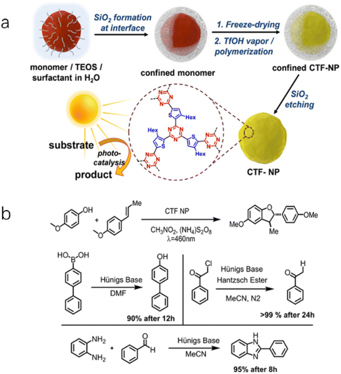
Liu et al.63 compared the photocatalytic HER activity of CTF-7 and CTF-8 synthesized using thiophene and furan as building blocks, respectively. The experimental results revealed that CTF-7 exhibited better performance than CTF-8 for the HER, primarily attributed to its polarized π electron distribution structure, which facilitated efficient charge separation. Thiourea derivatives can activate substrates in organocatalytic reactions by forming two hydrogen bonds through the acidic N-H groups. Building on this concept, the introduction of thiourea groups in CTFs enhanced their polarization and significantly promoted proton transfer as well as electron/hole accumulation at the N 2p and CO/CS groups.58 These thiourea functionalized CTFs were found to activate the two-electron reduction of O2 to H2O2 without sacrificial agents or cocatalysts, and the yields of H2O2 increased with the polarity of the thiourea moieties. Benzothiadiazole (BT) moieties are commonly employed in the design of organic photovoltaic materials. By incorporating electron-deficient BT moieties into the conjugated structure of CTFs (CTF-BT), the electronic structure can be tuned to enhance the performance of various photocatalytic reactions such as H2O2 production,59 syntheses of dibenzofuran, and organic reactions involving dehalogenation, hydroxylation, and benzoimidazole (Fig. 5).60
 | ||
| Fig. 5 (a) Synthetic route of CTF-BT nanoparticles. (b) Four photoredox reactions catalyzed by CTF-BT. Reproduced with permission from ref. 60. Copyright 2020, John Wiley and sons. | ||
Cooper et al. synthesized crystalline CTFs using benzobis (benzothiophene sulfone), and the obtained CTFs showed much higher HER activity compared to their amorphous or semicrystalline counterparts.61 The experimental data suggest that the high quantum efficiency of fused sulfone CTFs was attributed to their crystallinity, strong visible light absorption, and wettable hydrophilic pores.
The introduction of π-conjugation units effectively expands the π-conjugated system of CTFs, leading to a broader absorption of visible light and accelerated separation of electrons and holes. Carbon–carbon double bonds (–CC–)64 and triple bonds (–C![[triple bond, length as m-dash]](https://www.rsc.org/images/entities/char_e002.gif) C–)65 are considered as an effective π-bridge unit in organic semiconductor materials, which facilitates the extension of π-conjugation to improve the charge carrier mobility. Olefin or acetylene-linked COFs containing these double or triple bonds exhibit exceptional stability compared to their imine or C–C single-bond linked analogs. Furthermore, these COFs demonstrate intriguing properties such as magnetic coupling, electrochemical behavior, and photocatalytic activity, allowing their application in various fields.53,66,67 CTFs that contain sp2 carbon-conjugated linkages are renowned for their exceptional chemical stability and extended electron delocalization. These unique features have made them highly sought-after for various photocatalytic applications. For instance, researchers have utilized a Knoevenagel condensation approach to synthesize sp2-carbon-linked COFs with well-defined, crystalline honeycomb-like structures (Fig. 6).68 The obtained triazine-cored COFs with microfibrillar morphologies were used for the fabrication of thin film photoelectrodes, which exhibited good photocatalytic HER activity in the presence of ascorbic acid (AA) as an electron donor under visible light irradiation. Additionally, a novel sp2-carbon triazine-based COF has been synthesized using an acid-catalyzed aldol reaction, which exhibited satisfactory efficiency and reusability in organic dye photodegradation as well as C–H functionalization of heteroarenes and arenes.69 Electron spin resonance (ESR) spectroscopy has revealed the generation of superoxide radical anions as the dominant species responsible for degrading organic dyes, thus expanding the applications of sp2-carbon triazine-based COFs to photocatalytic aerobic reactions. For instance, olefin-linked CTFs have demonstrated selective oxidation of phenyl methyl sulfide with O2 under blue light irradiation.70,71
C–)65 are considered as an effective π-bridge unit in organic semiconductor materials, which facilitates the extension of π-conjugation to improve the charge carrier mobility. Olefin or acetylene-linked COFs containing these double or triple bonds exhibit exceptional stability compared to their imine or C–C single-bond linked analogs. Furthermore, these COFs demonstrate intriguing properties such as magnetic coupling, electrochemical behavior, and photocatalytic activity, allowing their application in various fields.53,66,67 CTFs that contain sp2 carbon-conjugated linkages are renowned for their exceptional chemical stability and extended electron delocalization. These unique features have made them highly sought-after for various photocatalytic applications. For instance, researchers have utilized a Knoevenagel condensation approach to synthesize sp2-carbon-linked COFs with well-defined, crystalline honeycomb-like structures (Fig. 6).68 The obtained triazine-cored COFs with microfibrillar morphologies were used for the fabrication of thin film photoelectrodes, which exhibited good photocatalytic HER activity in the presence of ascorbic acid (AA) as an electron donor under visible light irradiation. Additionally, a novel sp2-carbon triazine-based COF has been synthesized using an acid-catalyzed aldol reaction, which exhibited satisfactory efficiency and reusability in organic dye photodegradation as well as C–H functionalization of heteroarenes and arenes.69 Electron spin resonance (ESR) spectroscopy has revealed the generation of superoxide radical anions as the dominant species responsible for degrading organic dyes, thus expanding the applications of sp2-carbon triazine-based COFs to photocatalytic aerobic reactions. For instance, olefin-linked CTFs have demonstrated selective oxidation of phenyl methyl sulfide with O2 under blue light irradiation.70,71
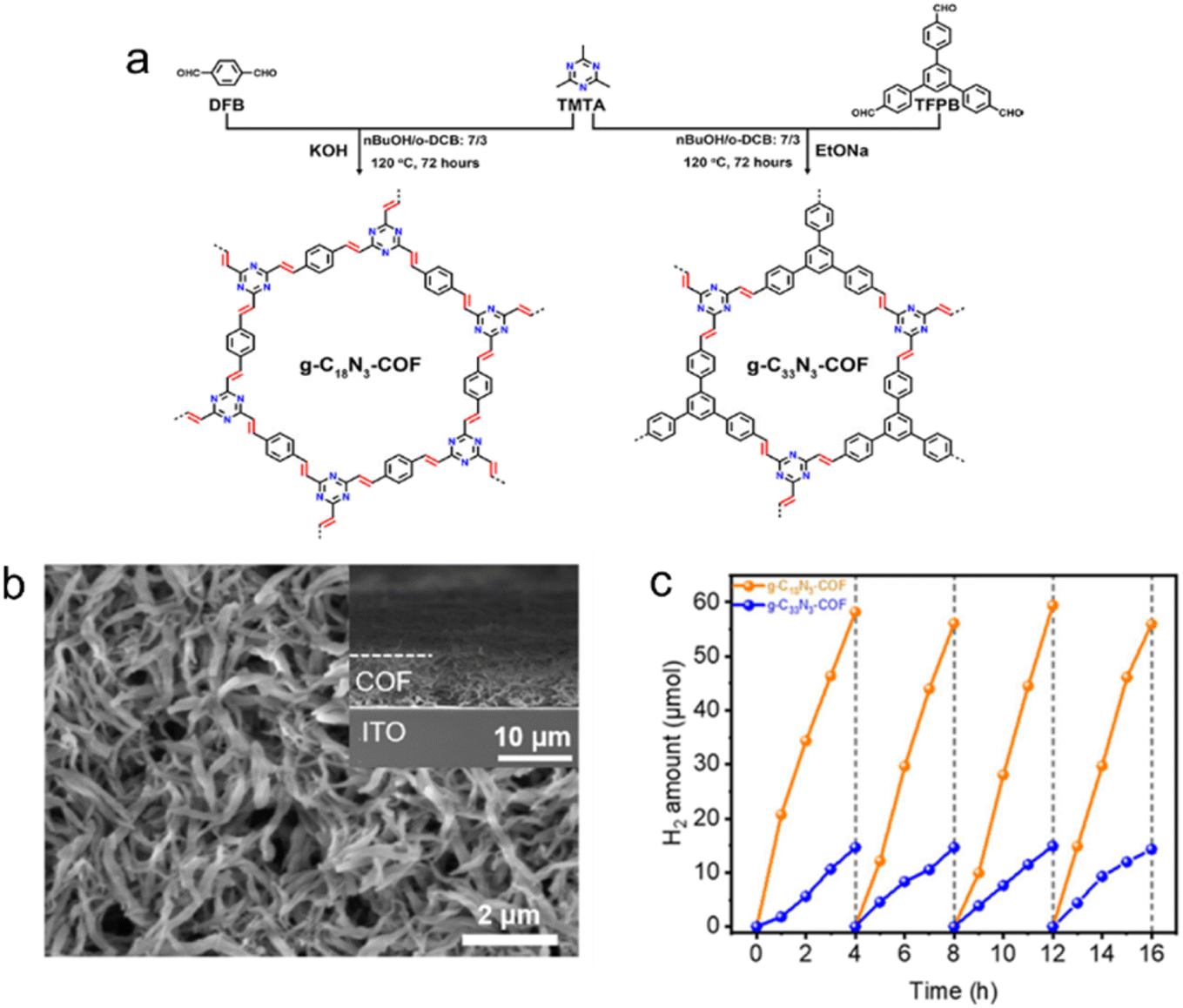 | ||
| Fig. 6 (a) Rational synthesis of g–C18N3–COF and g–C33N3–COF by Knoevenagel condensation. (b) The scanning electron microscopy (SEM) micrograph of the g–C18N3–COF film from the top view. (c) Photocatalytic H2 evolution of g–C18N3–COF and g–C33N3–COF under visible light irradiation by using ascorbic acid as a sacrificial agent. Reproduced with permission from ref. 68. Copyright 2020, American Chemical Society. | ||
The incorporation of acetylene (–CC–) or diacetylene (–CC–CC–) moieties in CTFs has been found to inhibit backward charge recombination, thereby extending the lifetime of charge carriers migrating from the donor to the acceptor. These –CC– and –CC–CC– moieties can significantly reduce the formation energy of OH* and facilitate a two-electron oxidation pathway for producing H2O2.72 The spatial separation between the triazine and acetylene cores further enhances charge separation and migration.73 Acetylene-bridged CTFs have demonstrated good performance in the selective oxidation of sulfides and oxidative coupling of amines under visible light irradiation.74,75 Optical and electronic analyses have demonstrated that the introduction of vinylene and acetylene moieties into the CTF skeleton promoted accelerated charge mobility and improved the visible light absorption capacity.74 The acetylene moiety, serving as a π-cross-linker within the framework, plays a crucial role in promoting exciton dissociation, minimizing exciton binding energy, and enhancing oxygen adsorption capacity for facilitating O2˙− and 1O2 formation in oxidative coupling reactions.75 CTFs containing triazine rings linked by both vinyl and acetylene groups, such as COF-TMT-A, have exhibited excellent performance in the photocatalytic CO2RR.76 In comparison to CTFs without acetylene groups, these materials demonstrated significantly improved photocatalytic performance for the CO2RR, with a remarkable 99% selectivity towards the product HCOO−.
Obviously, the introduction of specific functional groups plays a pivotal role in modulating the substrate affinity, conjugated structure, and inherent photoelectric characteristics of CTFs (Fig. 7). This modulation is advantageous for enhancing the adsorption of reaction substrates and facilitating the separation and transport of photogenerated electrons and holes. The deliberate design of CTFs with innovative and well-thought-out structures shows immense potential to boost the efficiency of photocatalytic reactions. It is important to note, however, that CTFs currently tend to display suboptimal photocatalytic performance when hosting various functional groups on their surface simultaneously.
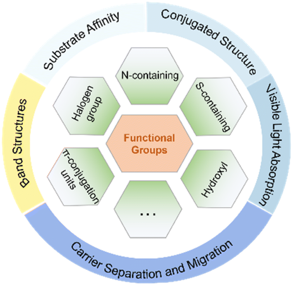 | ||
| Fig. 7 The roles of specific functional groups in modulating the characteristics of CTFs. | ||
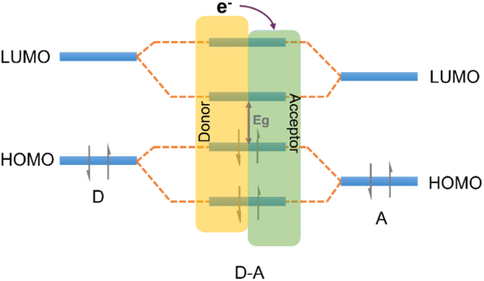 | ||
| Fig. 8 The effect of orbital coupling of donor and acceptor units on the bandgap and the transfer path of photogenerated electrons. | ||
The strategic modification of CTFs with donor–acceptor (D–A) units can enable the fine-tuning of their properties and facilitate anisotropic charge carrier migration, thereby enhancing the photocatalytic activity of CTFs. Recent studies have explored various D–A units, such as thiophene (Th),36,84,85 thieno[2,3-b]thiophene,86 phenyl,87 amide,88 benzodifuran (BDF),89 naphthalene,90 carbazole,80,91 triphenylamine,92 benzodithiophene (BDT),93 phenothiazine (PTZ)94 as electron donors and benzothiadiazole (BT)80,84 as an electron acceptor to design CTFs for photocatalytic applications (Table 2). Notably, in these D–A CTF materials, the role of triazine can vary, acting as either an electron donor or acceptor within the CTF structure, owing to the various electronic properties between triazine and the aforementioned moieties.85,87,91–93
| Donor | Acceptor | Photocatalyst | Reaction | Reactants | Light source | Production | Ref. |
|---|---|---|---|---|---|---|---|
| a TEOA: triethanolamine. b AA: ascorbic acid. c AQY: apparent quantum yield. | |||||||
| Carbazole | Triazine benzothiadiazole | 50 mg ter-CTF-0.7 2 wt% Pt | HER | H2O + TEOAa | 300 W Xe lamp (λ > 420 nm) | 19300 μmol h−1 g−1 AQYc = 22.8% at 420 nm |
80 |
| Thiophene | Benzothiadiazole | 50 mg CTF-0.5BT | HER | H2O + TEOA | 300 W Xe lamp (λ > 420 nm) | 2240 μmol h−1 g−1 AQY = 4% at 420 nm | 84 |
| Thiophene | Benzothiadiazole | 50 mg CTF-BT/Th-1 3 wt% Pt | HER | H2O + TEOA | 300 W Xe lamp (λ > 420 nm) | 6600 μmol h−1 g−1 AQE = 7.3% at 420 nm | 95 |
| Benzodifuran | Tris-(4-aminophenyl) triazine | 10 mg BDF-TAPT-COF 8 wt% Pt | HER | H2O + AA | 300 W Xe lamp (λ > 420 nm) | 1390 μmol h−1 g−1 AQY = 7.8% at 420 nm | 89 |
| Fluorene | Triazine | 50 mg CTF-N 2.11 wt% Pt | HER | H2O + TEOA | 300 W Xe lamp (λ > 420 nm) | 10760 μmol h−1 g−1 AQY = 4.07% at 420 nm |
91 |
| Pyrazole | Benzothiadiazole | 50 mg P1 3 wt% Pt | HER | H2O + TEOA | 300 W Xe lamp (λ > 420 nm) | 1000 μmol h−1 g−1 AQE = 1.43% at 420 nm | 101 |
| Triphenylamine | Triazine | 3 mg TtaTfa 8 wt% Pt | HER | H2O + AAb | 300 W Xe lamp (λ > 420 nm) | 20700 μmol h−1 g−1 AQE = 1.43% at 450 nm |
104 |
| Triazine | Benzodithiophene | 20 mg BDTCTF-1 3 wt% Pt | HER | H2O + TEOA | 300 W Xe lamp (λ > 420 nm) | 4500 μmol h−1 g−1 AQY = 3.9% at 420 nm | 105 |
| Triphenylamine | Triazine | 30 mg DA-CTF 3 μmol CoCl2·6H2O 0.1 mmol 2,2′-bipyridine | CO2RR | H2O + MeCN + TEOA | 300 W Xe lamp (λ > 420 nm) | 4 μmol CO after one hour 3 μmol H2 after one hour | 92 |
Thiophene or benzothiadiazole (BT) units have been introduced as dopants to enhance the charge carrier separation and migration in CTF-based photocatalysts. Experimental results and density functional theory (DFT) calculations have demonstrated that CTFs modified with Th or BT exhibit extended absorption of visible light and more efficient charge carrier transfer compared to pristine CTF-1.84 The incorporation of Th in the CTF promoted π-electron delocalization and facilitated charge transfer, as supported by DFT calculations.85 As a result, CTP-Th demonstrated remarkable photocatalytic activity in the hydrogenation of maleic acid and furfural, leading to the production of succinic acid and furfuryl alcohol, respectively. In addition, the introduction of a D (carbazole)-A1 (triazine)-A2 (benzothiadiazole) system led to a dramatically improved apparent quantum yield (AQY) of CTF to 22.8% at 420 nm, surpassing the performance of most conjugated porous polymers, which typically achieve AQYs within the range of 10% (Fig. 9).80 The bandgap of CTF-1 can be tuned in the range of 2.11 to 2.26 eV by adjusting the ratio of A2 in the structure and the LUMO energy values of CTF-1 became less negative as the amount of BT increased (Fig. 9e). To create molecular heterostructures, CTF-BT/Th was synthesized by incorporating benzothiadiazole (an electron-withdrawing unit) and thiophene (an electron-donating unit) into the covalent triazine frameworks through sequential polymerization.95 The resulting CTF-BT/Th exhibited a staggered bandgap arrangement at the heterojunction, resulting in significantly improved efficiency in charge carrier separation.
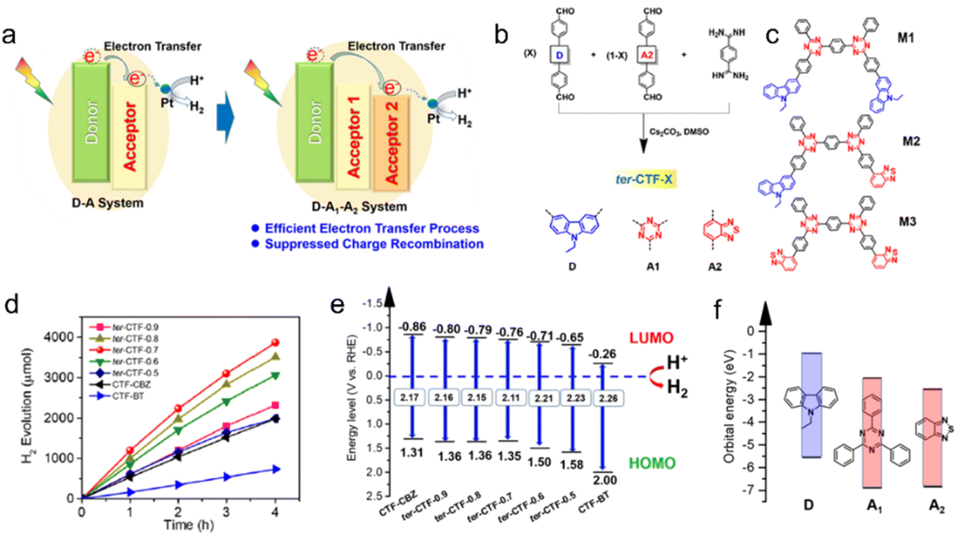 | ||
| Fig. 9 (a) The photoinduced electron-transfer process of the D–A system and D–A1–A2 system. (b) Rational synthesis of ter-CTF-X (X refers to the percentage of M-CBZ in the total aldehyde monomers). (c) Three proposed model fragments in ter-CTF-X (M1: CBZ combined with triazine; M2: CBZ combined with triazine and BT; and M3: BT combined with triazine). (d) Temporal photocatalytic H2 evolution over CTFs under visible light by using TEOA as a sacrificial agent. (e) The proposed energy alignments of CTFs based on experimental results. (f) The theoretical energy levels of building blocks. Reproduced with permission from ref. 80. Copyright 2019, American Chemical Society. | ||
A series of BDT-based CTFs were synthesized to investigate the structure–activity relationship in these materials with different D–A ratios.93 The experimental results showed that an appropriate D–A ratio in BDT-based CTFs led to efficient charge separation and low electron–hole recombination rates, which greatly promoted the photocatalytic activity for the HER.
The phenothiazine (PTZ) unit, known for its electron-rich tricyclic heteroaromatic structure containing strong electron-donating N and S atoms, is commonly utilized as an electron donor or hole transport material. Incorporating the PTZ unit in the CTF resulted in a broad visible light absorption range of CTF-PTZ. Additionally, CTF-PTZ demonstrated efficient charge separation and transfer, yielding a significant enhancement in the photocatalytic performance for the selective aerobic oxidation of sulfides to sulfoxides.94
Zhang et al. synthesized D–A CTFs containing thiophene (Th),96 diphenyl-thiophene (Th-Ph2) and diphenyl-benzothiadiazole (BT-Ph2)97 units directly on the surface of mesoporous silica (SBA-15). This approach aimed to combine the advantageous properties of both SBA-15 and D–A CTFs to form SBA-15-supported D–A CTF catalysts. These catalysts exhibited a high specific surface area, water compatibility, and demonstrated excellent photocatalytic performance in various reactions, such as the degradation of organic dyes, selective oxidation of styrene, selective oxidation of alcohols98 and partial oxidation of 5-hydroxymethylfurfural.99 Notably, these reactions were carried out in a solvent-free and solid-state environment, showcasing the potential of SBA-15-supported D–A CTF catalysts as efficient and versatile photocatalytic materials.
The introduction of different functional groups on the donor or acceptor units in D–A CTFs has a significant impact on their photoelectric properties. For instance, two CTFs containing naphthalene moieties (with and without methoxy groups) exhibited variations in morphology, CO2 adsorption capacity, and optical properties. The presence of methoxy groups on the naphthalene core also influenced these properties.90 Additionally, both DFT calculations and experimental results indicated that the conversion of the cyano group to amide functional groups led to a decrease in the bandgap of the CTF from 2.64 eV to 2.29 eV.88 The incorporation of amide groups as electron donors enhanced the visible light absorption and modified the band structure of the CTFs, thereby promoting the migration and separation of photogenerated charges. Jiang's group conducted DFT calculations to investigate the band alignment and charge transfer properties of potential D–A COFs employing various functional groups of tereph-thaldehydes as donors (Fig. 10).100 The exciton binding energy (Eb) is directly associated with the exciton effect exhibited by these COFs and the relative value of Eb corresponds to the strength of the D–A interactions. The activity trends of the COFs, as determined from the calculated and experimental data, aligned with the exciton effects predicted by DFT. This computer-aided design approach, enabling precise molecular structure tuning, contributes to the advancement of photocatalysts with exceptional performance.
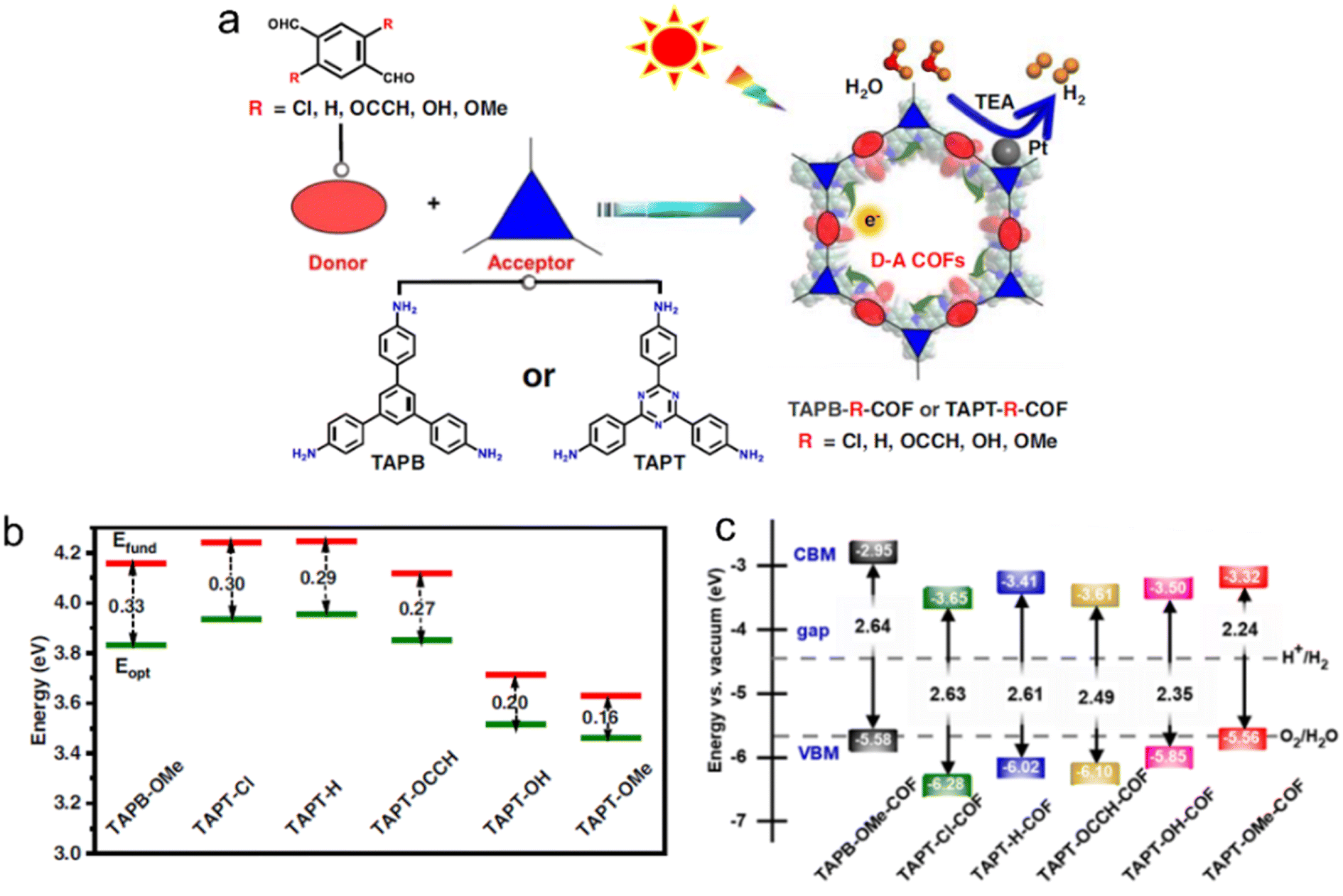 | ||
| Fig. 10 (a) D–A COFs constructed from amine monomers and functionalized tereph-thalaldehydes for photocatalytic H2 evolution under a 300 W Xe lamp (λ > 380 nm) by using triethylamine as a sacrificial agent. TAPB, TAPT and TEA indicate 1,3,5-tris(4-aminophenyl)benzene, 1,3,5-tris(4-aminophenyl)triazine and triethylamine, respectively. (b) Extrapolation results of fundamental gap (Efund, red line) and optical gap (Eopt, green line) energies of D–A pairs. Eb (exciton binding energy) = Efund − Eopt. (c) The calculated bandgap and band position of COFs relative to the vacuum level. The dashed lines are the redox potential of water at pH = 0. Reproduced with permission from ref. 100. Copyright 2023, Springer Nature. | ||
The one-atom substitution approach is commonly employed to design D–A-type conjugated porous polymers with specific optical bandgaps and aromatic properties.101 For instance, when using the same electron donor (pyrazole), CTFs with benzothiadiazole (S atom) as the electron acceptor exhibited superior photocatalytic HER activity in water compared to those with 2,1,3-benzoselenadiazole (Se atom) and 2,1,3-benzoxadiazole (O atom). The stronger electron acceptor, 2,1,3-benzoxadiazole (O atom), resulted in a broader bandgap and a more negative LUMO energy level, leading to poorer photocatalytic activity. Conversely, the weaker electron acceptor, 2,1,3-benzoselenadiazole (Se atom), caused a red shift in the absorption edge of visible light. However, it also led to an increase in bond length and a decrease in acceptor aromaticity, which negatively impacted the intramolecular charge transfer process and increased the electron–hole recombination rate. Furthermore, the substitution of fluorine atoms on the edge aromatic units improved the crystallinity and porosity of CTFs, which was beneficial for the efficient charge transfer of photogenerated carriers.102 The resulting F-substituted CTFs exhibited enhanced O2 chemisorption and achieved remarkable H2O2 yield rates under visible light illumination (λ > 400 nm). CTFs with S heteroatoms exhibited 5.6 times higher H2 evolution activity from H2O compared to CTFs with O heteroatoms.63 Gaussian and Mulliken calculations revealed that the migration of excited electrons from S heteroatoms to triazine units was more efficient than from O heteroatoms in CTFs. Electron paramagnetic resonance (EPR) spectra also indicated the generation of a greater number of electrons and holes in CTFs with S heteroatoms.
Protonation of CTFs has been demonstrated to enhance their hydrophilicity and increase the concentration of water molecules around the catalytic site.103 This protonation process leads to an obvious red-shift in light absorption, a substantial increase in charge separation efficiency, and an overall improvement in the hydrophilic properties of D–A-type imine-linked COFs, and thus enhanced photocatalytic performance.104
The extensive repertoire of organic molecules offers a diverse range of options for constructing CTFs, thereby bestowing them with remarkable structural versatility. Through meticulous and rational design strategies at the molecular level, precise control over the selection of precursor molecules exhibiting suitable electronic and spatial characteristics becomes achievable. This deliberate molecular engineering enables the fine-tuning of the structural and optoelectronic properties of CTFs, thereby enhancing their photocatalytic performance. The ability to modulate molecular structures plays a pivotal role in dictating the intricate relationship between the structure, property, and activity in these materials.
The strategy of constructing D–A structures has been proved to be effective in designing novel CTFs. By adjusting the degree of conjugation and electron affinity between the donor and acceptor, the absorption spectral range of CTFs is broadened, the exciton binding energy is reduced, and the photogenerated carriers are effectively separated and migrated in D–A CTFs. Currently, D–A CTFs are mainly constructed using binary monomers via covalent bonds, and there are still limited CTFs with ternary or poly D–A structures (e.g., D–A1–A2, D1–D2–A1, D1–A1–D2, etc.). Moreover, the choice of donor and acceptor and how to design a reasonable structure to maximize the advantages of the D–A structure are still in the theoretical stage. Further research is needed to explore these possibilities.
3.2 Structure engineering
Unlike the synthesis of typical COFs, achieving high crystallinity in CTFs poses a challenge due to the inherent stability of the triazine ring. The dynamic processes of covalent bond breaking and self-healing are not easily applicable to CTFs. Nevertheless, several methods have been developed to synthesize CTFs, such as the ionothermal method,111–115 superacid-catalyzed method,109,116–119 polycondensation method,25,120–122 and P2O5 (ref. 123) catalyzed method. For a more comprehensive exploration of COF synthesis methods, we direct the reader to refer to previous in-depth reviews on this topic.14,35
CTFs have been synthesized using the high-temperature ZnCl2 ionothermal route. However, the resulting CTFs had low crystallinity due to the irreversible carbonization process and reversible trimerization of nitrile, which allowed for the reorganization of the dynamic triazine backbone during synthesis.124,125 To mitigate the carbonization of the CTF skeleton, a three-salt eutectic mixture (NaCl/KCl/ZnCl2) was introduced as an alternative to pure ZnCl2. This approach enabled the synthesis of CTFs at lower temperatures while maintaining the desired crystallinity.126,127
Strong Brønsted acids, especially trifluoromethanesulfonic acid (CF3SO3H),109,116,128 are widely used catalysts for nitrite trimerization reactions in CTF synthesis, enabling lower temperature preparation. However, direct synthesis of CTFs using CF3SO3H often results in low crystallinity. To address this issue, microwave-assisted methods have been developed to enhance crystallinity by promoting dynamic triazine association and dissociation at lower temperatures.104 Microwave-assisted polymerization of highly ordered CTF-1 exhibited increased crystallinity with higher microwave power, although excessive power can distort the structure by damaging hexagonal units and extending the layer distance.129 Xu's group successfully developed a rapid and scalable microwave-assisted synthesis method for preparing a series of highly crystalline CTFs within 20 minutes. Moreover, this method can be easily scaled up to produce one hundred grams of CTFs.130 Notably, increased crystallinity led to a gradual narrowing of the bandgap of CTFs and a shift of the CB towards a more negative position. Subsequently, a scalable and eco-friendly method using polyphosphoric acid (H6P4O13) was developed by the same group, achieving superior crystallinity at the kilogram level.119 The crystallinity of CTFs prepared from H6P4O13 was superior to that of CTFs prepared from analogs P2O5 and H3PO4.123 Experimental and DFT results demonstrated that H6P4O13 has a lower activation energy for the nitrile trimerization reaction.
The polycondensation method offers a solution to the challenges posed by super acids, as it not only avoids their strong corrosive nature but also allows for control over the nucleation rate during the reaction.18 This method proves highly effective in improving the crystallinity of CTFs. In a study, four CTF-HUST samples were synthesized using the condensation reaction between aldehydes and diamine hydrochloride, involving the formation of Schiff base and subsequent Michael addition, as shown in Fig. 11.120 The maximum photocatalytic hydrogen production rate of CTF-HUST in aqueous solution (TEOA as a sacrificial agent) under visible light irradiation was obtained as 2647 μmol h−1 g−1. While the crystallinity of CTF-HUST was not optimal, the study suggests that controlled in situ oxidation of alcohols to form aldehyde monomers can significantly enhance the crystallinity of CTFs.131 The strategy of alcohol in situ oxidation promoted the formation of low-density nuclei and crystal growth of CTFs. This resulted in highly crystalline CTFs with enhanced visible light absorption up to approximately 850 nm, leading to dramatically improved photocatalytic performance in hydrogen evolution compared to less crystalline or amorphous CTFs. The presence of defects in amorphous CTF structures contributes to the recombination of photogenerated electron–hole pairs, which hinders their photocatalytic activity. Additionally, researchers have successfully synthesized highly crystalline CTFs with tailored pore structures by controlling the monomer feeding rate to regulate nucleation and crystal growth.110 In particular, under visible light illumination, the CTF-HUST-HC1 sample with exposed [001] crystal facets exhibited superior performance in the removal of nitric oxide (NO) compared to amorphous CTF-HUST-1 and even conventional g-C3N4 photocatalysts. Nonetheless, the hydrophobic nature of CTFs, stemming from their aromatic backbone, limited their applicability in aqueous medium. To address this, specific functional groups were incorporated into the monomers to modulate the hydrophilicity of CTFs. The dominant role of the base reagent t-BuOK in synthesizing CTFs with improved crystallinity and hydrophilicity using benzylamine-functionalized monomers has been highlighted.25 The crystallinity of CTFs was found to be enhanced with increasing strength of the base reagent. The resulting CTF-HUST-A1 exhibited excellent performance in the photocatalytic water splitting reaction, utilizing NiPx and Pt as cocatalysts without the need for sacrificial agents. In another study, aniline and aromatic co-solvents were utilized as dual modulators to synthesize CTFs with remarkable crystallinity.108 The crystalline CTFs were regulated through peripheral functionalization to enhance the oxidation of sulfides, achieving high conversion rates under blue LED irradiation.
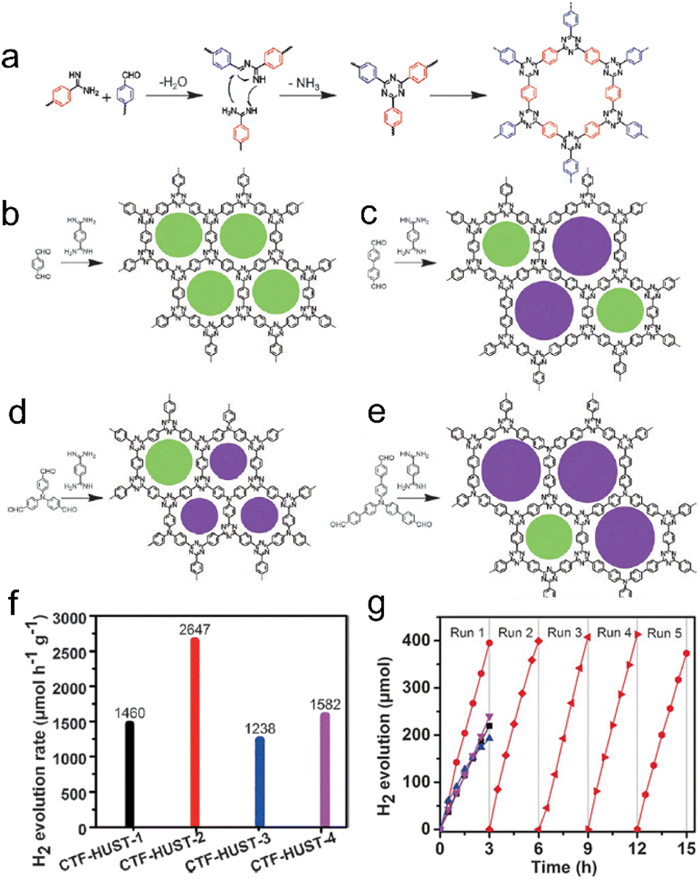 | ||
| Fig. 11 Rational synthesis of (a) CTF-HUST, (b) CTF-HUST-1, (c) CTF-HUST-2, (d) CTF-HUST-3, and (e) CTF-HUST-4. The circles filled with different colors represent two types of pores. HUST: Huazhong University of Science and Technology. (f) Photocatalytic H2 evolution rate of various CTF-HUSTs. (g) Photocatalytic H2 evolution of CTF-HUST-1, CTF-HUST-2, CTF-HUST-3 and CTF-HUST-4 and the stability test for CTF-HUST-2 for running over 5 times. The above photocatalytic experiments were done under visible light irradiation by using TEOA as a sacrificial agent. Reproduced with permission from ref. 120. Copyright 2017, John Wiley and sons. | ||
From a crystallinity perspective, high crystallinity in semiconductors typically promotes efficient charge transfer from the center to the surface, leading to enhanced photocatalytic activity. However, it has been observed that low crystallinity can also enhance photocatalytic activity in certain inorganic semiconductors by providing active centers for photocatalytic reactions through the generation of shallow trapping sites such as impurities and vacancies.132,133 Interestingly, similar observations have been made in the case of CTFs. It has been found that CTFs with low crystallinity sometimes exhibit better photocatalytic activity.134,135 The relationship between crystallinity and photocatalytic activity in CTFs is complex and multifaceted. It is possible that CTFs with different degrees of polymerization and crystallinity can form inherent electric fields between them, thereby improving the efficiency of charge carrier separation.
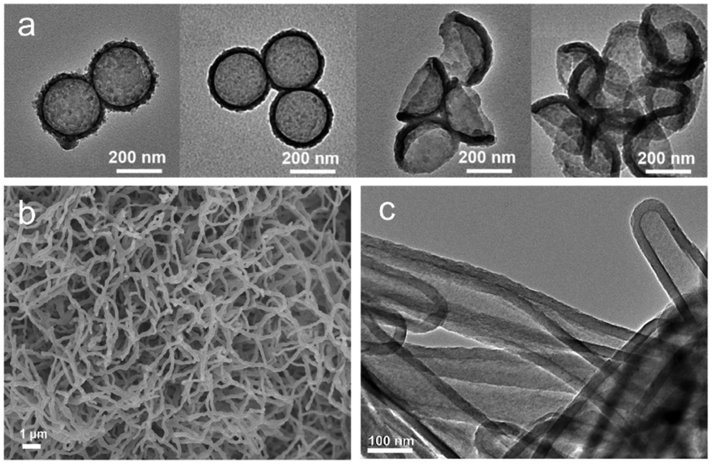 | ||
| Fig. 12 (a) The transmission electron microscope (TEM) images of different etched CTFs. Reproduced with permission from ref. 136. Copyright 2019, John Wiley and sons. (b) SEM and (c) TEM images of olefin-linked CTF nanotubes. Reproduced with permission from ref. 71. Copyright 2021, Elsevier. | ||
When a photocatalyst is exposed to sunlight, the photogenerated carriers must effectively migrate from the bulk phase to the photocatalyst surface to participate in the reaction. Few-layer CTF nanosheets offer a solution to this challenge as they shorten the charge migrate distance to the solid–liquid interface and provide more exposed active sites compared to bulk materials. Two main strategies are commonly employed to obtain few-layer CTFs: exfoliation and bottom-up synthesis.138,139 Exfoliation, in particular, has garnered significant interest due to its unique advantage of directly producing nanosheets from bulk COFs.
For instance, sulfuric acid was used as an intercalant and ammonium persulfate as an oxidant to exfoliate bulk CTFs into ultrathin CTF nanosheets.140 This process resulted in nanosheets with an extended visible light absorption edge up to 750 nm and a narrowed bandgap from 2.82 eV (pristine-CTF) to 2.36 eV. Experimental and DFT calculations showed that the conduction-band position of these ultrathin nanosheets was more favorable for promoting H2 evolution from water compared to that of the bulk CTF under visible light irradiation. In another study, researchers successfully prepared an ultrathin CTF nanosheet with a thickness of 1.5 nm using a redox exfoliation process.88 The resulting nanosheet exhibited distinct lamellar features and smooth morphology after 30 drop-casting cycles and demonstrated a competitive H2 evolution rate of 25.7 mmol h−1 m−2 among reported film devices.
Furthermore, a glycerol intercalation strategy was employed to exfoliate bulk CTFs into crystalline sheets (E-CTF-HC1).141 The exfoliation process was found to be influenced by the vibrational states of glycerol molecules at different temperatures. N-doped quantum dots (CTFQDs) were obtained by exfoliating and cutting CTFs in piranha solution, resulting in a blue shift in the UV-vis spectra compared to bulk CTFs.142 Ultrasonic assistance and grinding/ball milling have been widely used for the exfoliation of two-dimensional materials by overcoming interlayer interactions. For instance, Wang's group successfully prepared exfoliated CTF143 and fluorinated CTF144 nanosheets through mechanical milling processes. Micrometer-sized few-layer CTF sheets were obtained through micromechanical cleavage and liquid sonication.145 However, CTF thin films prepared using these mechanical methods often exhibit lower crystallinity.
Bottom-up synthesis is another effective method for producing thin films of CTFs, allowing for large-area, controllable thickness films in a single step. One general approach to synthesizing porous CTF membranes with intrinsic porosity involves catalyzing aromatic nitrile trimerization reactions at low temperatures using super acids. Dai117 and Chung,146 for example, used CF3SO3H for in situ catalytic synthesis of CTF membranes on glass, although controlling the thickness, size, and crystallinity of these films can be challenging. Therefore, the two-phase interface synthesis method has been developed, which involves the trimerization of carbonitrile at the interface of CH2Cl2 and CF3SO3H to synthesize single-layer/few-layer triazine-based two-dimensional polymers (2DPs).147 The high-resolution transmission electron microscopy (HR-TEM) images demonstrated the high structural order of these 2DPs.
Additionally, a mixture of 1,4-dicyanobenzene and CH2Cl2 has been used to prepare few-layer 2D-CTF-1 nanosheets.148 Wang et al. achieved the synthesis of single-layer CTF nanosheets with a thickness of approximately 1.1 nm through a combination of interface synthesis, mild oxidation, and ultrasonic-assisted exfoliation.149 Moreover, Tan et al. developed an innovative organic solvent/air interfacial polymerization method to prepare large-area, thickness-controlled semicrystalline CTF films (Fig. 13).122 These films exhibited a high hydrogen evolution rate of 5.4 mmol h−1 m−2, attributed to their good light absorption, large lateral size, and crystal structure. In a recent development, monolayer-assisted surface-initiated Schiff-base-mediated aldol polycondensation was utilized to prepare large-area crystalline CTF films on various solid substrates.150 The resulting films demonstrated lateral sizes of up to 120 cm2 and tunable thicknesses ranging from tens of nanometers to a few micrometers.
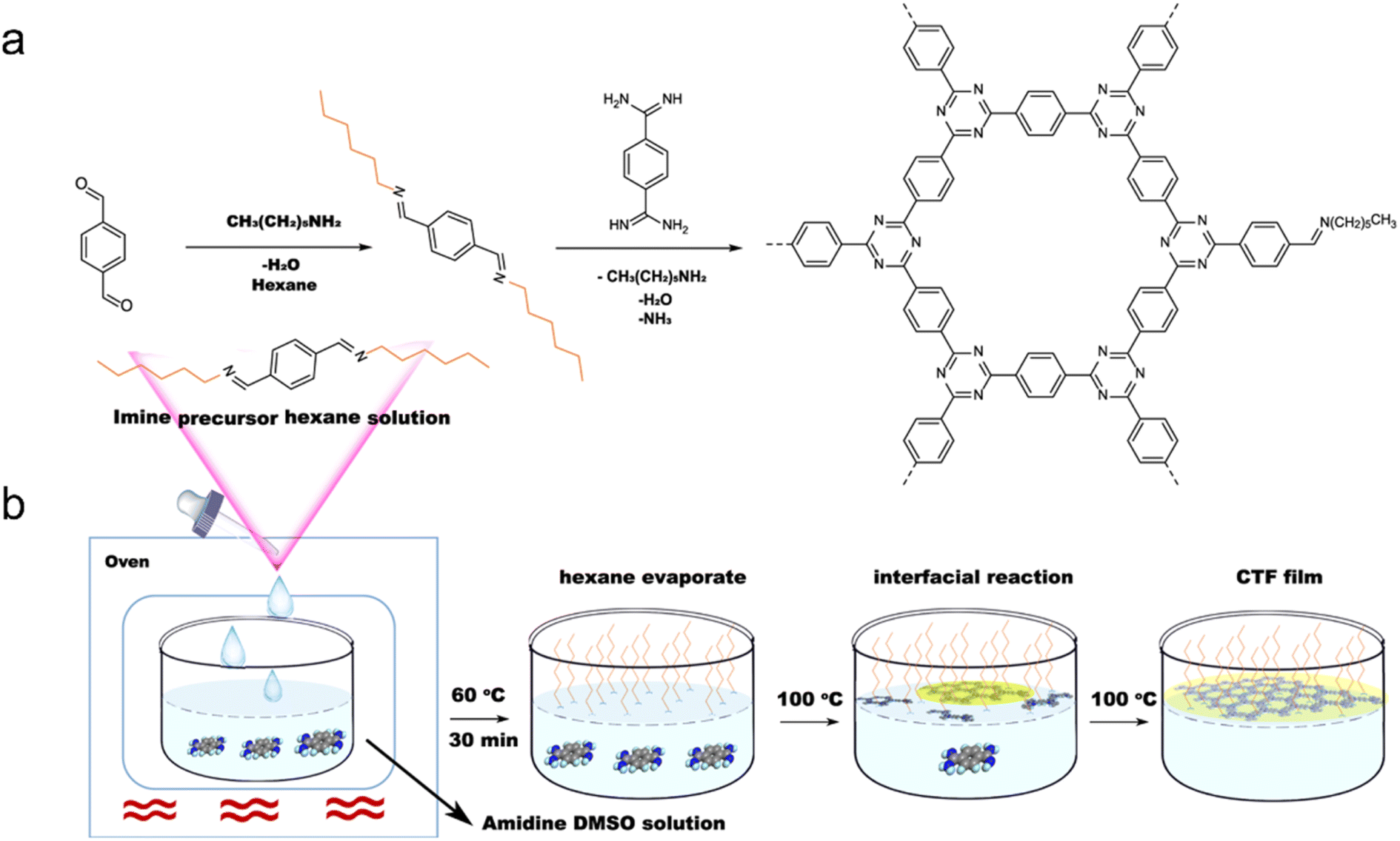 | ||
| Fig. 13 (a) Rational synthesis of CTFs. (b) Synthetic procedure for the fabrication of CTF films on the dimethyl sulfoxide (DMSO) surface assisted by the imine precursor. Reproduced with permission from ref. 122. Copyright 2021, Springer Nature. | ||
The low-dimensional structure and reduced particle size of CTF films serve to shorten the migration distance for photogenerated carriers while increasing the active sites on the surface. Both exfoliation and interfacial synthesis methods, which are commonly used, are effective for synthesizing CTF films. However, compared to exfoliation which produces small-area and inhomogeneous thin films, interfacial synthesis is more favorable for producing large-area films with a controllable number of layers, offering the potential to design and prepare photocatalytic devices based on CTF films in the future.
For instance, the introduction of halogen elements through chemical doping has been shown to significantly decrease the bandgap of CTFs.153 Specifically, Cl doping resulted in a narrower bandgap of 2.48 eV than pristine CTF (bandgap: 2.94 eV), leading to an approximately 6.1 times increase in the H2 evolution rate from water splitting (TEOA as a sacrificial agent) under visible light (Fig. 14). This improvement can be attributed to the more negative CB position of the Cl-doped CTF, which facilitates more efficient charge transfer. DFT and experimental result analyses indicated that the formation of Cl–N and Cl–C bonds in CTFs promotes electron delocalization and accelerates charge carrier transportation.154
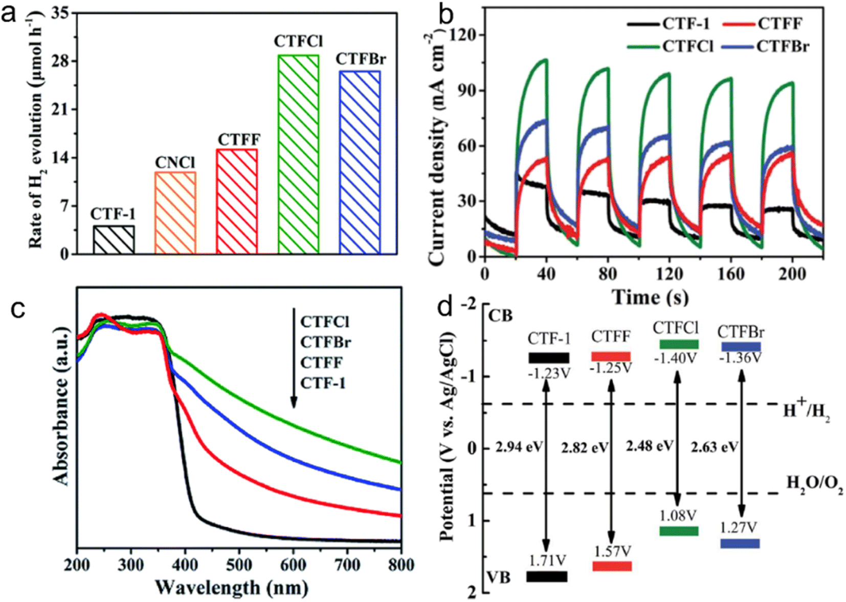 | ||
| Fig. 14 (a) Photocatalytic H2 evolution rates over CTF-1, CNCl and CTFX (X = Cl, F, Br) samples under visible light illumination by using TEOA as a sacrificial agent. (b) Photocurrent responses over CTF-1 and CTFX photoelectrodes under visible-light irradiation. (c) UV-vis DRS spectra of CTF-1 and CTFX. (d) Electronic band structure of CTF-1 and the CTFX samples (versus the saturated Ag/AgCl reference electrode at pH = 7). Reproduced with permission from ref. 153. Copyright 2019, Royal Society of Chemistry. | ||
N-doped CTFs (T3N-CTF) have been achieved through Schiff-base condensation reactions using 5,5′,5′′-(1,3,5-triazine-2,4,6-triyl)tris(pyridine-2-amine) as the monomer.155 Both triazine nitrogen and pyridine nitrogen have been identified as active sites in the CTF. The incorporation of specific nitrogen atoms within the framework of T3N-CTF has shown improvements in light absorption, surface area expansion, and enhanced charge separation efficiency. Additionally, a simple hydrothermal treatment of CTF-1 with hydrazine hydrate has enabled the synthesis of self-doped nitrogen CTFs (NCTF-1).156 NCTF-1 exhibited a CH4 generation rate of 11.48 μmol g−1 h−1 in the photocatalytic CO2RR, which was nine times higher than that of CTF-1. The excess nitrogen in NCTF-1 provided a CO2-friendly scaffold for selective adsorption and separation of CO2.
Similarly, P doping in CTF-1 promoted its hydrogen evolution performance, exhibiting a rate approximately 4.5 times higher than that of undoped CTF-1.157 Moreover, P-doped CTF-1 maintained high stability in H2 evolution over a 20-hour cyclic reaction without significant changes in its crystal structure.
Furthermore, the introduction of a small amount of sulfur effectively altered the electronic properties and energy band structure of CTFs.158 Photoelectric characterization studies revealed that S-doped CTFs exhibited a narrower bandgap, broader absorption edge, and reduced recombination of photogenerated carriers than bare CTFs.
Doping other elements in organic semiconductor materials, especially in CTFs, is indeed more challenging compared to inorganic semiconductor materials. CTFs consist of carbon, hydrogen, nitrogen, and other non-metallic elements linked by covalent bonds, and doping often requires breaking the original covalent bond, which can damage the conjugated structure and reduce the crystallinity of CTFs. Additionally, controlling the precise position of the doped atoms within the CTF structure is difficult. These challenges make the process of doping other elements in CTFs more complex and less controllable compared to inorganic semiconductors.
3.3 Heterostructures
| Heterojunction | Photocatalyst | Reaction | Reactants | Light source | Production | Ref. |
|---|---|---|---|---|---|---|
| a LA: lactic acid. b TEOA: triethanolamine. c MeCN: acetonitrile. d AA: ascorbic acid. e AQY: apparent quantum yield. | ||||||
| Type-II | 20 mg CdS NPs/3% CTF-1 1 wt% Pt | HER | H2O + LAa | 300 W Xe lamp (λ > 420 nm) | 12150 μmol h−1 g−1 |
165 |
| 20 mg 20% CdS-CTF-1 1 wt% Pt | HER | H2O + LA | 300 W Xe lamp (λ > 420 nm) | 11430 μmol h−1 g−1 AQYe = 16.3% 420 nm |
166 | |
| 10 mg NH2-UiO-66/COF 3 wt% Pt | HER | H2O + TEOAb | 300 W Xe lamp (λ > 400 nm) | 8440 μmol h−1 g−1 | 177 | |
| Z-scheme | 10 mg 5 wt%CuCo2O4/CTF-1 7.0 mg [Ru(bpy)3]Cl2·6H2O | CO2RR | H2O + TEOA + MeCNc | 300 W Xe lamp (λ > 420 nm) | 14.9 μmol h−1 g−1 CO | 167 |
| 50 mg COP-ZnIn2S4 1 wt% Pt | HER | H2O + Na2S + Na2SO3 | 300 W Xe lamp | 5040 μmol h−1 g−1 | 171 | |
| 50 mg Au@TiO2-12%TrTh 3% Pt | HER | H2O + TEOA | 300 W Xe lamp (λ > 420 nm) | 4288.54 μmol h−1 g−1 | 179 | |
| 15 mg 60-TiO2@CTF-Py 0.045 mM CoCl2 | CO2RR | H2O | 300 W Xe lamp (λ > 320 nm) | CO selectivity: 98.3% 43.34 μmol h−1 g−1 CO | 180 | |
| NCTS-2 | CO2RR | MeCN + AAd | 300 W Xe lamp | CO selectivity:100% 7.51 μmol CO after 4 h AQY = 6.81% 365 nm | 182 | |
| 20 mg SnS2/S-CTFs | CO2RR | TEOA + H2O | 300 W Xe lamp (λ > 420 nm) | 123.6 μmol h−1 g−1 CO 43.4 μmol h−1 g−1 CH4 | 187 | |
In a type-II heterojunction (Fig. 15a) between photocatalyst A (PC A) and photocatalyst B (PC B), electron and hole pairs are generated in both PC A and PC B upon illumination.164 The electrons from PC A are transferred to PC B, while the holes move from PC B to PC A in the opposite direction. As a result, PC B accumulates electrons for reduction reactions and PC A accumulates holes for oxidation reactions. This spatial separation of charge carriers allows for efficient reactions on each photocatalyst, enhancing overall photocatalytic performance. For instance, the combination of CdS and CTF exhibited a photocatalytic H2 production rate of 12150 μmol g−1 h−1 from water under visible light irradiation, which was approximately 3 times higher than that of pure CdS.165 This enhanced performance can be attributed to the strong interaction and matched band potentials between CdS and CTF, which facilitated the delocalization of photogenerated carriers out of the CTF plane and effectively suppressed the photocorrosion of CdS induced by photogenerated holes. Additionally, the CTF served not only as a supporter but also as a photocatalyst and an electron donor within the composite structure.166
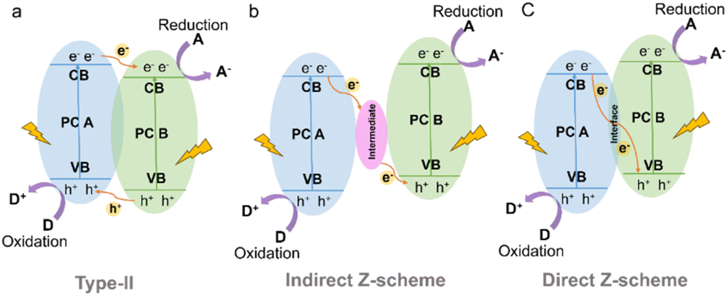 | ||
| Fig. 15 Schematic illustration of the electron-transfer route in a combined system using two kinds of semiconductors with (a) type-II (b) indirect Z-scheme and (c) direct Z-scheme heterojunctions. | ||
The Z-scheme heterojunction consists of two semiconductors with a similar band structure to that of the type-II heterojunction, but with different electron–hole transfer paths, as shown in Fig. 15.167 In the Z-scheme heterojunction, the electrons from the CB of PC A combine and annihilate with the holes from the VB of PC B through either a suitable intermediate (indirect Z-scheme heterostructure) (Fig. 15b) or direct contact interface (direct Z-scheme heterostructure) (Fig. 15c).168 This arrangement leads to a spatial separation of electrons and holes, with electrons accumulating in the CB of PC B and holes accumulating in the VB of PC A, leading to a higher redox capability.
For example, the coupling of CdS and CTF-1 in a membrane configuration exhibited outstanding photocatalytic sterilization effects in photocatalytic in situ cleaning and disinfection due to the generation of abundant hole pairs as well as reactive oxygen species, solving the stubborn fouling problems of 2D membranes.169 In addition, a Z-scheme SnS2/sulfur-bridged CTF (S-CTF) photocatalyst (SnS2/S-CTFs) was developed, exhibiting efficient CO2 adsorption due to the CO2-friendly nature of S-CTFs and promoting efficient separation of photogenerated carriers. Such SnS2/S-CTFs exhibited exceptional visible-light-driven CO2 photoreduction activity, generating CO and CH4.170 ZnIn2S4 (ZIS) is a sulfide photocatalyst with a tunable bandgap (2.06–2.85 eV).171 Despite its high photogenerated electron efficiency, the recombination of photogenerated carriers remains an issue. By constructing a Z-scheme heterojunction between a porphyrin-based CTF and ZIS, effective charge separation was achieved. Experimental and theoretical calculations demonstrated that photogenerated electrons were transferred via the Z-scheme route, overcoming the speed-limiting step in photocatalytic hydrogen evolution.
Due to their excellent optical properties and electronic conductivity, 2D materials such as carbon nitride (C3N4) and black phosphorus (BP) nanosheets have been extensively explored to form heterojunctions with CTFs and enhance the visible light absorption and charge transfer properties of CTF-based photocatalysts.172–174 For instance, integration of 2D C3N4 with a CTF resulted in a metal-free heterostructure with a type I band alignment, facilitating efficient charge migration. The hybrid material exhibited remarkable stability and high selectivity for the photocatalytic CO2RR to produce CO during 3 cyclic runs in 30 h by using [Co(bpy)3]2+ as the cocatalyst.172 Similarly, the incorporation of BP nanosheets into a CTF enabled highly active photocatalytic H2 evolution at a rate of 17.1 mmol h−1 g−1 in water (formaldehyde as a sacrificial agent) under a 300 W xenon lamp with full spectrum.173 The crucial P–C bonding at the interface promoted electron transfer, while the accumulation of electrons on BP nanosheets prevented surface oxidation. Furthermore, a sandwich-type CTF-BP-Pt photocatalyst was fabricated by depositing Pt on BP, forming a bridge joint with Pt(δ+)–P(δ−)–N(δ+) surface bonding states, enabling efficient charge separation and extending the light absorption range of the hybrid material.175 A type II heterojunction was also constructed using a triphenylphosphine-based COF (P-COF) and CTF.176 The interaction between P-COF and the CTF expanded the visible spectrum utilization and facilitated the transfer of photogenerated carriers, resulting in a hydrogen production rate approximately 2.5 times higher than that of pristine CTF.
Metal–organic frameworks (MOFs) have been extensively applied in photocatalytic fields due to their electrical conductivities and manifold building structure. Similar to porous crystalline materials, MOFs can be well integrated with CTFs to fabricate hybrid materials with rapid charge transfer and good stability. For instance, in the case of NH2-UiO-66 (Zr), the dissolution of the link between the carboxyl in 2-aminoterephthalic acid and Zr2+ of NH2-UiO-66 (Zr) in alkaline environments limits its practical application as a photocatalyst. To overcome this issue, a CTF was anchored on the surface of NH2-UiO-66 (Zr) to slow down its decomposition. The resulting hybrid material (NH2-UiO-66/CTF-3wt% Pt) demonstrated a hydrogen production rate of 8.44 mmol h−1 g−1 in alkaline aqueous solution (TEOA as a sacrificial agent) under a 300 W Xe lamp (400 nm cutoff filter) and could be recycled up to 10 times with consistent performance.177 As another example, a conductive 2D MOF (Ni-CAT-1) was tightly grafted onto a CTF to create a Z-scheme heterostructure through a unique coordinating connection between the dual N sites of the CTF terminal amidine groups and Ni ions of Ni-CAT-1.178 The transient photocurrent density of Ni-CAT-1/CTF-1 was more than twice as high as that of pure Ni-CAT-1 and CTF-1, indicating the superior separation and migration ability of the composite. The hybrid material also exhibited high activity for H2 evolution under visible light.
Metal oxide semiconductors such as TiO2, CuCo2O4 and ZnFe2O4 have been successfully combined with CTFs to fabricate organic–inorganic hybrid materials for photocatalytic solar fuel production.167,179–181 As an example, the Au@TiO2-X%TrTh Z-scheme heterojunction, comprising CTF-based TrTh, TiO2, and Au nanoparticles, demonstrated high activity for photocatalytic hydrogen production in aqueous solution (TEOA as a sacrificial agent) under visible light irradiation.179 This was attributed to the synergetic effect of the localized surface plasmon resonance of Au nanoparticles and the Z-scheme electron transfer pathway for photogenerated carriers. Additionally, a Co2+-immobilized pyridine CTF (CTF-Py) decorated on an NH2−-functionalized TiO2 (NH2-TiO2) surface enabled the conversion of CO2 into CO using H2O as the electron donor without the need for additional sacrificial agents.180 The excited electrons transfer from TiO2 to CTF-Py, accumulating at the metal sites on the hybrid material surface for reducing CO2, while the holes concentrate on the TiO2 surface for H2O oxidation. The formation of a Z-scheme heterojunction between the staggered band structures of TiO2 and CTF-Py facilitated electron–hole separation and photoinduced charge transfer. Defect TiO2 anchored on a CTF through a well-defined chemical bonding between the amine group of the CTF and Ti3+ also achieved efficient photocatalytic CO2 conversion.182 The large surface area of the CTF provided rich adsorption sites for CO2, and the Ti-N facilitated the selective conversion of CO2 into CO with a selectivity of approximately 100%. Similarly, the direct Z-scheme heterojunction between p-type semiconductor CuCo2O4 and CTF-1 allowed for the efficient photocatalytic conversion of CO2 into CO. Electron spin resonance (ESR) analysis revealed that photogenerated holes tended to accumulate in the valence band of CuCo2O4, while electrons transferred to the conduction band of CTF-1, achieving spatial separation of electrons and holes.167 ZnFe2O4 is a promising visible-light-responsive photocatalyst due to its narrow bandgap while being resistant to photochemical corrosion. When ZnFe2O4 was combined with a CTF, the band gap energy of CTF-1 was reduced, resulting in a broadened range of visible light absorption. Therefore, the obtained ZnFe2O4/CTF exhibited excellent performance in the photocatalytic degradation of methylene blue (MB).181 In comparison to ZnFe2O4/CTF, ZnFe2O4/FeP-CTF exhibited a higher exposure of (311) crystal planes and a larger surface area, which facilitated closer contact between CO2 and the active sites. The strong interaction between ZnFe2O4 and FeP-CTF enhanced interfacial charge transfer and separation, thereby leading to improved reaction performance in photocatalytic CO2 reduction (Fig. 16a).183
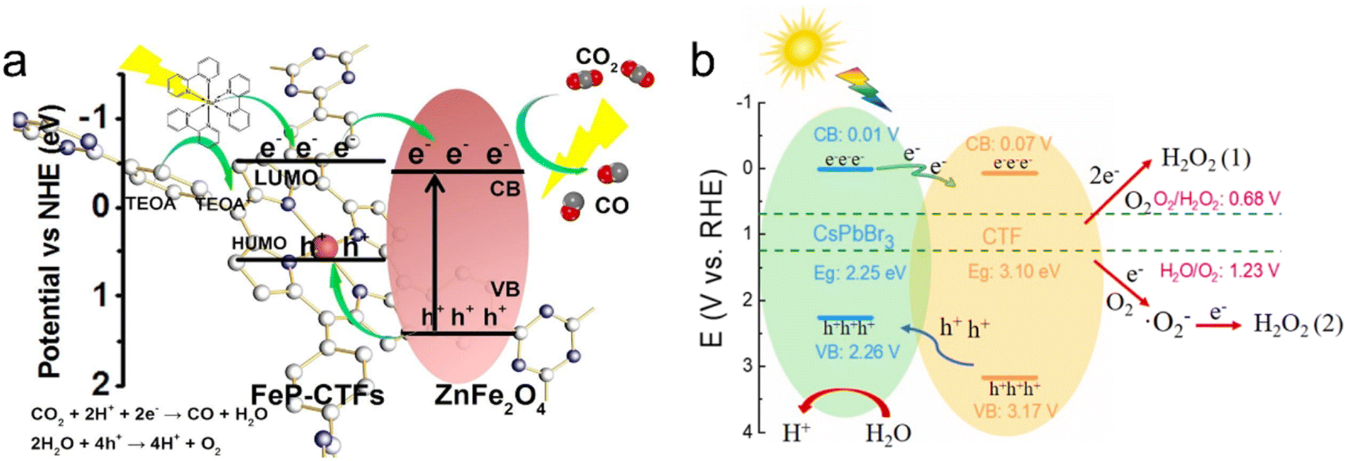 | ||
| Fig. 16 The proposed charge transfer mechanisms: (a) ZnFe2O4/FeP-CTF for the photocatalytic CO2 reduction system. Reproduced with permission from ref. 183. Copyright 2021, Elsevier. (b) CsPbBr3/CTF-2 for photocatalytic H2O2 production. Reproduced with permission from ref. 186. Copyright 2022, Elsevier. | ||
Metal halide perovskites are well known for their promising photocatalytic properties, characterized by their high molar extinction coefficients and tunable light absorption.184 In a study, CsPbBr3 quantum dots (QDs) were immobilized on CTF-1 for photocatalytic CO2 reduction to CO, resulting in an AQY of over 0.07% at 450 nm. CTF-1 acted as a suitable support with abundant cavities for adsorbing and activating CO2, while also enhancing the charge transfer ability of CsPbBr3 QDs.185 Similarly, CsPbBr3/CTFs demonstrated excellent performance in photocatalytic H2O2 production. The photogenerated holes oxidize H2O to produce hydrogen H+, while the electrons migrate from CsPbBr3 to the surface of the CTF to react with adsorbed O2 to produce H2O2via a one-step two-electron reaction pathway and two-step one-electron reaction path (Fig. 16b).186
The design concept of heterojunction materials has been widely utilized in photocatalysis, facilitated by the built-in electric field in the heterojunction that drives the separation of photogenerated electrons and holes. By selecting semiconductor materials with matching energy band structures and Fermi energy levels to CTFs, the efficiency of photogenerated carrier separation and migration can be significantly improved, thereby enhancing the photocatalytic performance. While CTFs and organic semiconductors can often be effectively contacted through interactions like π–π and electrostatic adsorption, achieving effective contact with inorganic semiconductors poses a challenge. In many cases, the electrostatic adsorption between CTFs and inorganic semiconductors cannot overcome the density difference, resulting in separation and the inability to fully exploit the benefits of a heterojunction structure in the photocatalytic reaction. However, it has been reported that modifying the surface of the inorganic semiconductor can facilitate the formation of covalent bonds with CTFs, enhancing the contact force and offering insights for future design on the composites of CTFs and inorganic materials.
Cu,189 Co,191,201 Ru202 and Re203 are of great interest due to their considerable catalytic activity in the photocatalytic CO2RR. As an example, Cu single atoms confined into CTF-1 effectively enhanced the visible light absorption and the CO2 adsorption capacity of CTF-1, with a production selectivity of CH4 over 98.31% in the photocatalytic CO2RR.189 DFT calculations confirmed the synergic effect of the single atom metal sites and CTF host, reducing the reaction energy barriers for forming *COOH intermediates and accelerating CO2 adsorption and desorption of produced gas.190In situ diffuse reflectance infrared Fourier transform spectroscopy (DRIFTS) assisted by DFT demonstrated that the transition of *COOH to *CO species is more thermodynamically favorable on Fe single atoms/CTF surface compared with the pure CTF surface. Moreover, the specific atomic-level interaction is more inclined to dissociate *CO into CO instead of further CO* protonation to CHO* and therefore exhibited high CO selectivity in the CO2 reduction process. CTFs confining Co single atoms were used for efficient CO2RR and H2 production, enabling an efficiency far surpassing those of Co nanoparticles/CTFs and pure CTFs.204 Numerous literature results indicate that metal ions anchored on bipyridyl and porphyrin-based COFs improve the CO2 photoreduction performance.205–207 The bipyridyl-CTF coordinated with Ru202 and Re203 single atoms showed good activity in the photocatalytic CO2RR to form formate and CO, respectively, with a formate production rate of 2090 μmol g−1 h−1, and a turnover number (TON) of 4.8 for CO2-to-CO conversion. Recently, the fully conjugated viCOF-bpy-Re was synthesized through an aldol condensation reaction by incorporating a rhenium complex and triazine ring structures (Fig. 17a and b). viCOF-bpy-Re exhibited an outstanding performance for converting CO2 into CO under visible light by using H2O as a sacrificial agent (Fig. 17c–e).208 DFT results further revealed the excited intramolecular charge transfer process from the triazine ring unit to the Re–bipyridine complex. As another example, a Co-porphyrin-based CTF was synthesized under mild conditions to preserve the structure of porphyrin units, showing good charge separation ability in photoluminescence spectra.209 Additionally, the high N content of CTFs endowed this catalyst with a strong CO2 adsorption capacity, exhibiting better activity in the photocatalytic CO2RR with a CO yield of 2562.8 μmol g−1 h−1 (Fig. 17f).
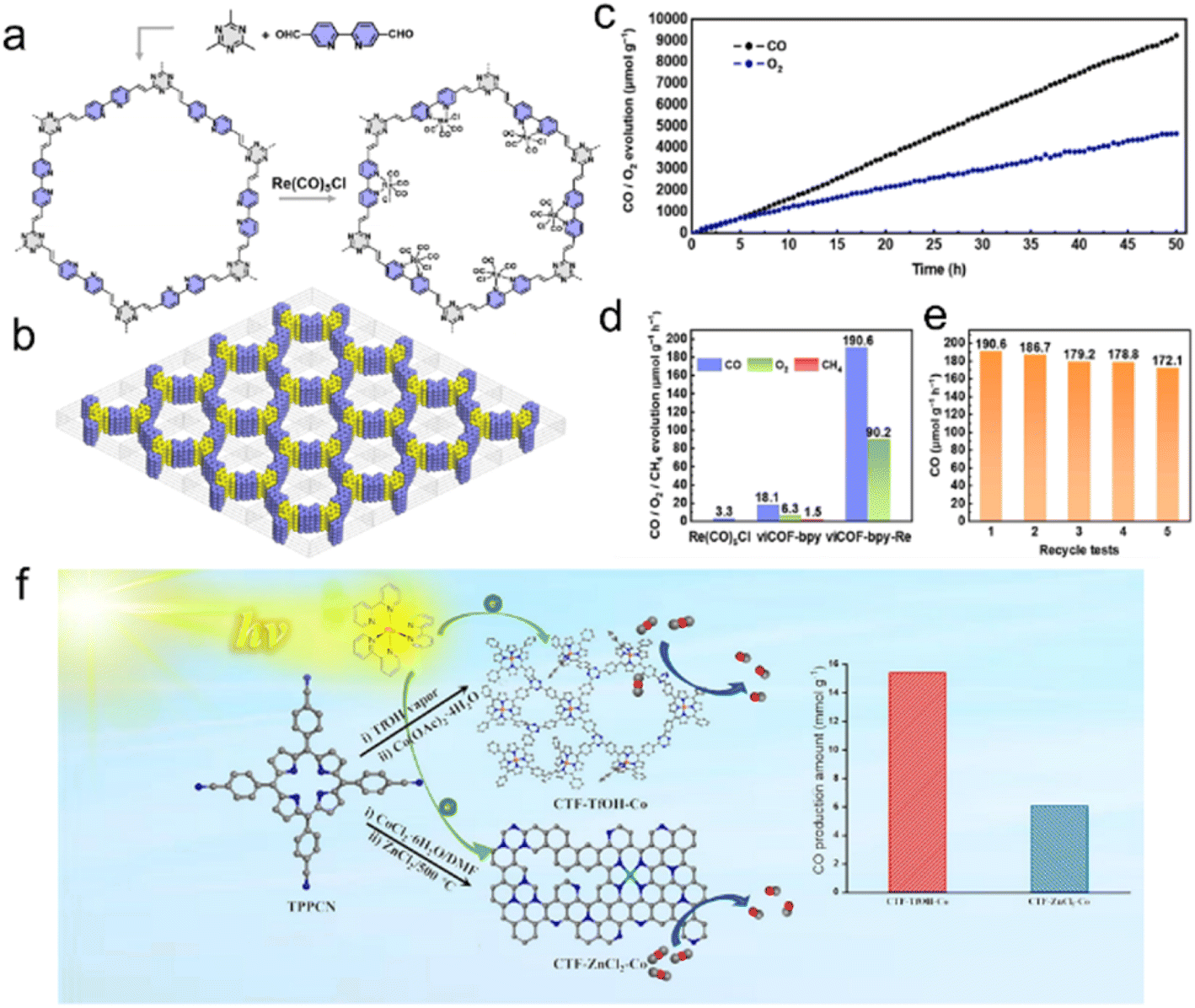 | ||
| Fig. 17 (a) The synthesis of viCOF-bpy and viCOF-bpy-Re. (b) Diagram of the alternating arrangement of bipyridine and triazine ring units. (c) Time-dependent CO and O2 production performance of viCOF-bpy-Re. (d) Photocatalytic CO2 reduction performance of the Re-complex, viCOF-bpy, and viCOF-bpy-Re. (e) Stability tests of viCOF-bpy-Re. Reproduced with permission from ref. 208. Copyright 2023, John Wiley and Sons. (f) Porphyrin-based CTFs for photocatalytic CO2 reduction. Reproduced with permission from ref. 209. Copyright 2023, Elsevier. | ||
Single-atom catalyst-loaded CTFs fully harness the catalytic ability of metal atoms, with their ultra-high atom utilization enhancing the photocatalytic performance and reducing the amount of precious metal required. However, to maximize the catalytic performance of metal atoms, it is essential to consider the introduction of effective ligand units into the structure of CTFs.
Transition metal phosphides (TMPs) have gained significant attention in the field of photocatalysis due to their exceptional electrical conductivity, cost-effectiveness, and versatile composition. For instance, Ni2P alloys have shown excellent performance in photocatalytic H2 evolution from water, making them a potential alternative to Pt as a cocatalyst.211 Previous studies have confirmed that 2.8 wt% Ni2P alloys-CTF demonstrated comparable H2 evolution rates (5.84 mmol h−1 g−1) to 3.0 wt% Pt/CTF (∼6.1 mmol h−1 g−1) under visible light irradiation.212 Similarly, Co2P nanocrystals anchored on CTFs using a simple phosphidation strategy resulted in a P-CTF-Co2P photocatalyst, which exhibited outstanding photocatalytic H2 evolution activity (7.6 mmol h−1 g−1) among CTF-based hybrid materials with non-platinum cocatalysts.213 Co2P accumulated rich electrons via the interfacial P–C bonds for reducing protons to produce H2. Further investigations have revealed that the Pδ−–Coδ+–Nδ− state in the CTF/CoP complex induced by the polarization effect of the N site facilitated the adsorption and dissociation of H2O, as shown in Fig. 18.214
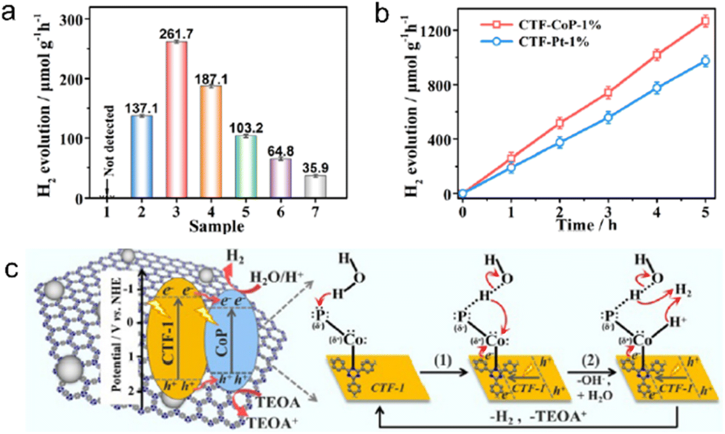 | ||
| Fig. 18 (a) Photocatalytic H2 evolution over (1) CTF-1 or CoP, CTF-CoP photocatalysts with different contents of CoP: (2) 0.5%, (3) 1%, (4) 3%, and (5) 5%, (6) physically immobilized CTF/CoP-1% and (7) physically mixed CTF-1 + CoP-1%. (b) Photocatalytic H2 evolution rate over CTF-CoP-1% and CoP-Pt-1%. (c) The possible mechanism of charge transfer over the obtained CTF-CoP-1% for photocatalytic H2 evolution. The above experiments were done under visible light irradiation by using TEOA as a sacrificial agent. Reproduced with permission from ref. 214. Copyright 2022, Royal Society of Chemistry. | ||
Carbon materials such as carbon quantum dots (CQDs), carbon nanotubes (CNTs), and graphene oxide (GO) have found widespread use in various fields, including photocatalysis, electrocatalysis, sensing, and bioimaging, attributable to their unique photoelectric properties, quantum confinement effects, high photochemical stability, and environmentally friendly nature.215–217 In the study of CQDs/CTFs for photocatalytic hydrogen evolution from water, photoelectrochemical characterization revealed that the introduction of CQDs not only extended the visible light response range but also helped in electron storage, with the light emitted in its multiphoton active process being captured by CTF-1 to enhance the separation of photogenerated electron–hole pairs.218 Moreover, when the CTF was combined with the electronic conductivity mediator CNT, the Schottky barrier was reduced, which facilitated the transfer of photogenerated charges from the CTF bulk to the surface catalytically active sites, resulting in an almost complete reduction of Cr(VI) under visible light irradiation for 2 hours.219 Additionally, the combination of π-conjugation-linked CTF-1 with GO was found to boost photocatalytic H2 evolution, with GO enhancing the hydrogen production efficiency of the CTF by nine times at a content of 3% under visible light irradiation through the π-conjugation effect between them.217 The uniform thin GO layer not only acted as an electron transport “bridge” to facilitate the separation of photogenerated charges but also shortened the distance of electron migration.
The research on replacing precious metals and other co-catalysts represents a highly practical and significant endeavor. The investigation of the composite structure of CTFs, as mentioned earlier, has instilled confidence in the potential replacement of precious metal co-catalysts like Pt and Rh with non-precious metal compounds. These studies offer crucial experimental data to support the quest for cost-effective and efficient co-catalysts for hydrogen and oxygen evolution reactions.
4. Conclusions and perspectives
CTFs possess triazine ring structures with a robust conjugated system, ample nitrogen content, exceptional visible light absorption, high chemical stability, substantial specific surface area, and versatile modifiability. These outstanding properties render CTFs highly advantageous for photocatalytic hydrogen and oxygen evolution from water in the presence of sacrificial reagents, overall water splitting, CO2 reduction, and organic reactions. Nonetheless, CTFs do exhibit certain defects and boundaries that hinder the transmission of photogenerated electrons, leading to suboptimal separation efficiency of photogenerated carriers and significant electron–hole recombination.This review highlights various strategies to overcome these challenges and enhance the photocatalytic performance of CTFs (Table 4). By designing and constructing new types of CTFs, such as by introducing organic functional groups and leveraging the synergistic effect between functional groups and triazine rings, the intrinsic photoelectric properties of CTFs, such as bandgaps, photogenerated carrier separation, and recombination efficiency, can be regulated. In addition, the D–A theory serves as a valuable tool for designing and synthesizing high-performance photocatalytic materials. The conjugation system in the D–A structure, with different electron affinity and ionization energy between the donor and acceptor, broadens the visible light absorption range and facilitates the transfer of photogenerated electrons from the donor to the acceptor. This acceleration of photogenerated electron–hole pair separation increases the electron transport rate within the molecule and reduces the recombination sites for electrons and holes.
| Strategy | Absorption of photons | Charge migration | Surface reaction |
|---|---|---|---|
| Introducing functional groups | ✓ | ✓ | ✓ |
| Donor–acceptor | ✓ | ✓ | — |
| Improving crystallinity | ✓ | ✓ | — |
| Morphology and thickness | ✓ | ✓ | — |
| Doping | ✓ | ✓ | ✓ |
| Heterojunction | ✓ | ✓ | ✓ |
| Single-atom | — | ✓ | ✓ |
| Composite structures | ✓ | ✓ | ✓ |
The high crystallinity of semiconductor materials contributes to fewer defects, which in turn reduces the recombination sites for electrons and holes. However, during the synthesis of CTFs, poorly reversible self-healing often results in unsatisfactory crystallinity, particularly for non-imine bonded CTFs. To address this issue, several synthesis methods have been developed, including ionothermal, superacid-catalyzed, polycondensation, polyphosphoric acid-catalyzed, and microwave-assisted methods. Among these, microwave-assisted synthesis and polyphosphoric acid methods have shown potential for large-scale synthesis of high crystallinity CTFs. Photocatalytic reactions rely on the efficient migration of photogenerated electrons to the surface of semiconductors. However, CTFs tend to stack up and form bulk materials due to π–π interactions between layers, which hinders the effective diffusion of charges to the active center. In contrast, single-layer or oligomeric CTF nanosheets have the advantages of short migration paths for photogenerated electrons and tunable optoelectronic properties. Therefore, the preparation of single-layer or oligomeric CTFs by exfoliation or interfacial synthesis is considered as an approach to enhance the photocatalytic performance of CTFs.
Semiconductor doping is a conventional method used to improve the photocatalytic performance of inorganic semiconductor materials. Similarly, doping heteroatoms into the CTF framework can significantly alter its band structure, broaden the light absorption range, and enhance carrier mobility. Thus, doping is also a viable approach to enhance the photocatalytic performance of CTFs. Moreover, constructing heterostructures can effectively promote the separation and migration of photogenerated carriers in CTFs. By utilizing electrostatic adsorption, covalent bonding, and π–π interactions, CTFs can form heterostructures with other semiconductors such as inorganic semiconductor materials, MOFs, and COFs, leading to type-II and Z-scheme heterostructures. This enables efficient transfer of photogenerated carriers on the contact surface between them, effectively separating electron–hole pairs. Additionally, the composites of single atoms and CTFs provide abundant active sites for reactions and enhance the conductivity of catalysts, improving the mobility of photogenerated electrons.
Although the photocatalytic performance of CTFs has shown notable advancements through the aforementioned research and theoretical studies, it is essential to acknowledge that there is still room for improvement. The structure–activity relationship of CTFs also requires further detailed investigation.
We believe that investigating the following aspects of CTFs will be crucial for future applications:
4.1 Development of green and scalable synthesis methods
The excellent stability and nitrogen-rich structure of CTFs not only make them promising for photocatalytic applications but also popular in electrocatalysis, industrial catalysis, and other fields.143,220–222 There is an urgent need to develop a more green, safe, and cost-effective process for large-scale synthesis of high-quality CTFs to meet the demands of various industries.4.2 Design of novel structure CTFs and CTFs-organic semiconductor heterojunctions
The strategies summarized above to improve the photocatalytic performance of CTFs aim to broaden the visible light absorption range of CTFs, improve the separation efficiency of photogenerated carriers, shorten the migration paths of photogenerated electrons and holes, and reduce crystal defects of CTFs. For that purpose, by combining the advantages of various strategies, CTFs with high visible light absorption efficiency, high crystallinity, and single-layer or oligolayer D–A structures can be designed and synthesized. Based on the easy modification of CTFs with other organic semiconductor materials, the CTFs-organic semiconductor heterojunction constructed through electrostatic adsorption or covalent bonding easily regulates the band structure and promotes the separation and migration of photogenerated carriers.4.3 Mechanistic studies of CTFs in photocatalytic reactions
In-depth investigations are necessary to fully understand the mechanisms of CTFs in photocatalytic reactions, especially the impact of D–A structures on their performance. Currently, the understanding of the effect of D–A structures is largely based on theoretical calculations, and there is a lack of relevant experimental characterization. Advanced characterization techniques such as steady-state fluorescence emission100 and time-resolved electron paramagnetic response (TREPR) spectroscopy223 can provide valuable experimental evidence for studying the photogenerated electron–hole separation and transfer states during photocatalytic reactions. Such studies would contribute to a comprehensive understanding of the role of D–A structures in enhancing the photocatalytic performance of CTFs.4.4 Photocatalytic CO2RR application
CTFs show advantages in adsorbing CO2 due to their N-rich characteristics. However, the research on the photocatalytic CO2RR is still in its initial stages, and in most cases, the CO2 reduction product is CO. Developing efficient photocatalysts for the photocatalytic CO2RR to produce valuable organic compounds holds great promise and presents an attractive avenue for further research.4.5 Exploration of 3D CTFs
Most current CTF research focuses on 2D structures and less work has been done on 3D CTFs.224 The novel structure of 3D CTFs may offer unexpected optoelectronic properties, breaking the barriers of 2D materials.4.6 Utilizing intelligent computing tools
The design of new CTFs for photocatalytic applications is often based on existing literature and the experiences of researchers, which may not always lead to optimal photocatalytic properties. To address this challenge, the utilization of machine learning intelligent computing tools to pre-design high-performance photocatalysts,100,225 combined with high-throughput technology226 for rapid prediction of the catalytic performance of CTFs, can significantly improve the efficiency of developing new and advanced catalysts. By leveraging these advanced techniques, researchers can swiftly identify promising CTF candidates with enhanced photocatalytic properties and expedite the discovery of high-performance photocatalysts for various applications.In summary, although still in its early stages, the exciting research on using CTF-based materials for photocatalytic applications is already laying the groundwork for effective modification strategies and design rules to enhance their photocatalytic performance. With this strong and encouraging foundation, future efforts hold the promise of having a significant impact on solar fuel and chemical production.
Author contributions
All the authors contributed to the paper. Yubing Liu: writing – original draft, visualization, and funding acquisition. Hao Wu: writing – original draft and visualization. Qian Wang: supervision, writing – review & editing, and funding acquisition.Conflicts of interest
There are no conflicts to declare.Acknowledgements
This work was supported by the JSPS Leading Initiative for Excellent Young Researchers program (to Q. W.), the JST Fusion Oriented REsearch for disruptive Science and Technology program (GAN JPMJFR213D, to Q. W.) and the National Natural Science Foundation of China (no. 22002058, to Y. L.).Notes and references
- A. P. Côté, A. I. Benin, N. W. Ockwig, M. Keeffe, A. J. Matzger and O. M. Yaghi, Science, 2005, 310, 1166 CrossRef PubMed.
- H. Wang, Y. Yang, X. Yuan, W. Liang Teo, Y. Wu, L. Tang and Y. Zhao, Mater. Today, 2022, 53, 106–133 CrossRef CAS.
- H. Wang, H. Wang, Z. Wang, L. Tang, G. Zeng, P. Xu, M. Chen, T. Xiong, C. Zhou, X. Li, D. Huang, Y. Zhu, Z. Wang and J. Tang, Chem. Soc. Rev., 2020, 49, 4135–4165 RSC.
- G. B. Wang, S. Li, C. X. Yan, F. C. Zhu, Q. Q. Lin, K. H. Xie, Y. Geng and Y. B. Dong, J. Mater. Chem. A, 2020, 8, 6957–6983 RSC.
- K. Kamiya, Chem. Sci., 2020, 11, 8339–8349 RSC.
- G. Zhang, X. Li, Q. Liao, Y. Liu, K. Xi, W. Huang and X. Jia, Nat. Commun., 2018, 9, 2785 CrossRef PubMed.
- R. Liu, K. T. Tan, Y. Gong, Y. Chen, Z. Li, S. Xie, T. He, Z. Lu, H. Yang and D. Jiang, Chem. Soc. Rev., 2021, 50, 120–242 RSC.
- C. Qian, W. Zhou, J. Qiao, D. Wang, X. Li, W. L. Teo, X. Shi, H. Wu, J. Di, H. Wang, G. Liu, L. Gu, J. Liu, L. Feng, Y. Liu, S. Y. Quek, K. P. Loh and Y. Zhao, J. Am. Chem. Soc., 2020, 142, 18138–18149 CrossRef CAS PubMed.
- D. Zhu, G. Xu, M. Barnes, Y. Li, C. P. Tseng, Z. Zhang, J. J. Zhang, Y. Zhu, S. Khalil, M. M. Rahman, R. Verduzco and P. M. Ajayan, Adv. Funct. Mater., 2021, 31, 2100505 CrossRef CAS.
- J. Wang and S. Zhuang, Coord. Chem. Rev., 2019, 400, 213046 CrossRef CAS.
- Y. Mou, X. Wu, C. Qin, J. Chen, Y. Zhao, L. Jiang, C. Zhang, X. Yuan, E. Huixiang Ang and H. Wang, Angew. Chem., Int. Ed., 2023, e202309480 CAS.
- C. Krishnaraj, H. S. Jena, K. Leus and P. Van Der Voort, Green Chem., 2020, 22, 1038–1071 RSC.
- T. Sun, C. Wang and Y. Xu, Chem. Res. Chin. Univ., 2020, 36, 640–647 CrossRef CAS.
- R. Sun and B. Tan, Chem. Res. Chin. Univ., 2022, 38, 310–324 CrossRef CAS.
- Y. Zhang and S. Jin, Polymers, 2019, 11, 31 CrossRef PubMed.
- Z. F. Qian, Z. J. Wang and K. A. I. Zhang, Chem. Mater., 2021, 33, 1909–1926 CrossRef CAS.
- H. Wang, L. Guan, J. Liu, T. Lei, Y. Xue, Z. Qu, S. Jin, H. Ma and Z. Guo, J. Mater. Chem. A, 2022, 10, 16328–16336 RSC.
- L. Guo, X. Wang, Z. Zhan, Y. Zhao, L. Chen, T. Liu, B. Tan and S. Jin, Chem. Mater., 2021, 33, 1994–2003 CrossRef CAS.
- Z. Qian, Z. J. Wang and K. A. I. Zhang, Chem. Mater., 2021, 33, 1909–1926 CrossRef CAS.
- F. Niu, L. Tao, Y. Deng, H. Gao, J. Liu and W. Song, New J. Chem., 2014, 38, 5695–5699 RSC.
- C. Yang, W. Huang, L. C. da Silva, K. A. I. Zhang and X. Wang, Chem.–Eur. J., 2018, 24, 17454–17458 CrossRef CAS PubMed.
- Y. Cong, X. Chen, W. Wang and S. W. Lv, New J. Chem., 2021, 45, 21278–21284 RSC.
- H. Lin, C. Chen, T. Zhou and J. Zhang, Sol. RRL, 2020, 5, 2000458 CrossRef.
- M. Liu, L. Guo, S. Jin and B. Tan, J. Mater. Chem. A, 2019, 7, 5153–5172 RSC.
- S. Zhang, G. Cheng, L. Guo, N. Wang, B. Tan and S. Jin, Angew. Chem., Int. Ed., 2020, 59, 6007–6014 CrossRef CAS PubMed.
- S. Tao and D. Jiang, CCS Chem., 2021, 3, 2003–2024 CrossRef CAS.
- Q. Wang and K. Domen, Chem. Rev., 2020, 120, 919–985 CrossRef CAS PubMed.
- J. Ozdemir, I. Mosleh, M. Abolhassani, L. F. Greenlee, R. R. Beitle and M. H. Beyzavi, Front. Energy Res., 2019, 7, 77 CrossRef.
- A. Fujishima and K. Honda, Nature, 1972, 238, 37–38 CrossRef CAS PubMed.
- H. W. Li, Z. Guan, Y. Cheng, T. Lui, Q. Yang, C. S. Lee, S. Chen and S. W. Tsang, Adv. Electron. Mater., 2016, 2, 1600200 CrossRef.
- S. Zhu and D. Wang, Adv. Energy Mater., 2017, 7, 1700841 CrossRef.
- X. Chang, T. Wang and J. Gong, Energy Environ. Sci., 2016, 9, 2177–2196 RSC.
- E. Gong, S. Ali, C. B. Hiragond, H. S. Kim, N. S. Powar, D. Kim, H. Kim and S. I. In, Energy Environ. Sci., 2022, 15, 880–937 RSC.
- V. S. Vyas, F. Haase, L. Stegbauer, G. Savasci, F. Podjaski, C. Ochsenfeld and B. V. Lotsch, Nat. Commun., 2015, 6, 8508 CrossRef CAS PubMed.
- R. Sun and B. Tan, Chem.–Eur. J., 2023, 29, e202203077 CrossRef CAS PubMed.
- S. Zhang, F. Zhao, G. Yasin, Y. Dong, J. Zhao, Y. Guo, P. Tsiakaras and J. Zhao, J. Colloid Interface Sci., 2023, 637, 41–54 CrossRef CAS PubMed.
- G. Tuci, M. Pugliesi, A. Rossin, C. Pham-Huu, E. Berretti and G. Giambastiani, Chemistryselect, 2022, 7, e20220356 Search PubMed.
- P. Puthiaraj and W. S. Ahn, J. Energy Chem., 2017, 26, 965–971 CrossRef.
- R. Luo, W. Xu, M. Chen, X. Liu, Y. Fang and H. Ji, ChemSusChem, 2020, 13, 6509–6522 CrossRef CAS PubMed.
- Y. Zou, S. Abednatanzi, P. Gohari Derakhshandeh, S. Mazzanti, C. M. Schüßlbauer, D. Cruz, P. Van Der Voort, J. W. Shi, M. Antonietti, D. M. Guldi and A. Savateev, Nat. Commun., 2022, 13, 2171 CrossRef CAS PubMed.
- Y. Sun, W. Li, Z. Wang, J. Shi and Z. Jiang, Curr. Opin. Biotechnol., 2022, 73, 67–73 CrossRef CAS PubMed.
- M. R. Hoffmann, S. T. Martin, W. Choi and D. W. Bahnemann, Chem. Rev., 1995, 95, 69–96 CrossRef CAS.
- X. An, T. Li, B. Wen, J. Tang, Z. Hu, L. M. Liu, J. Qu, C. P. Huang and H. Liu, Adv. Energy Mater., 2016, 6, 1502268 CrossRef.
- R. Abe, J. Photochem. Photobiol., C, 2010, 11, 179–209 CrossRef CAS.
- Y. Sasaki, A. Iwase, H. Kato and A. Kudo, J. Catal., 2008, 259, 133–137 CrossRef CAS.
- W. Kurashige, Y. Mori, S. Ozaki, M. Kawachi, S. Hossain, T. Kawawaki, C. J. Shearer, A. Iwase, G. F. Metha, S. Yamazoe, A. Kudo and Y. Negishi, Angew. Chem., Int. Ed., 2020, 59, 7076–7082 CrossRef CAS PubMed.
- F. Haase, T. Banerjee, G. Savasci, C. Ochsenfeld and B. V. Lotsch, Faraday Discuss., 2017, 201, 247–264 RSC.
- L. De Bruecker, J. Everaert, P. Van Der Voort, C. V. Stevens, M. Waroquier and V. Van Speybroeck, ChemPhysChem, 2020, 21, 2489–2505 CrossRef CAS PubMed.
- H. Liu, C. Li, H. Li, Y. Ren, J. Chen, J. Tang and Q. Yang, ACS Appl. Mater. Interfaces, 2020, 12, 20354–20365 CrossRef CAS PubMed.
- A. López-Magano, N. Salaverri, L. Marzo, R. Mas-Ballesté and J. Alemán, Appl. Catal., B, 2022, 317, 121791 CrossRef.
- M. Alves Fávaro, D. Ditz, J. Yang, S. Bergwinkl, A. C. Ghosh, M. Stammler, C. Lorentz, J. Roeser, E. A. Quadrelli, A. Thomas, R. Palkovits, J. Canivet and F. M. Wisser, ACS Appl. Mater. Interfaces, 2022, 14, 14182–14192 CrossRef PubMed.
- Y. Yang, X. Chu, H. Y. Zhang, R. Zhang, Y. H. Liu, F. M. Zhang, M. Lu, Z. D. Yang and Y. Q. Lan, Nat. Commun., 2023, 14, 593 CrossRef CAS PubMed.
- Z. Zhao, X. Chen, B. Li, S. Zhao, L. Niu, Z. Zhang and Y. Chen, Adv. Sci., 2022, 9, 2203832 CrossRef CAS PubMed.
- V. S. Vyas, F. Haase, L. Stegbauer, G. Savasci, F. Podjaski, C. Ochsenfeld and B. V. Lotsch, Nat. Commun., 2015, 6, 8508 CrossRef CAS PubMed.
- G. Cheng, K. Wang, S. Wang, L. Guo, Z. Wang, J. Jiang, B. Tan and S. Jin, Sci. China Mater., 2021, 64, 149–157 CrossRef CAS.
- H. Wang, L. Guan, J. Liu, T. Lei, Y. Xue, Z. Qu, S. Jin, H. Ma and Z. Guo, J. Mater. Chem. A, 2022, 10, 16328–16336 RSC.
- Q. Sheng, X. Zhong, Q. Shang, Y. Dong, J. Zhao, Y. Du and Y. Xie, Front. Chem., 2022, 10, 854018 CrossRef CAS PubMed.
- C. Wu, Z. Teng, C. Yang, F. Chen, H. B. Yang, L. Wang, H. Xu, B. Liu, G. Zheng and Q. Han, Adv. Mater., 2022, 34, 2110266 CrossRef CAS PubMed.
- X. Yu, B. Viengkeo, Q. He, X. Zhao, Q. Huang, P. Li, W. Huang and Y. Li, Adv. Sustainable Syst., 2021, 5, 2100184 CrossRef CAS.
- W. Huang, N. Huber, S. Jiang, K. Landfester and K. A. I. Zhang, Angew. Chem., Int. Ed., 2020, 59, 18368–18373 CrossRef CAS PubMed.
- X. Wang, L. Chen, S. Y. Chong, M. A. Little, Y. Wu, W.-H. Zhu, R. Clowes, Y. Yan, M. A. Zwijnenburg, R. S. Sprick and A. I. Cooper, Nat. Chem., 2018, 10, 1180–1189 CrossRef CAS PubMed.
- W. Zhang, Z. Deng, J. Deng, C. T. Au, Y. Liao, H. Yang and Q. Liu, J. Mater. Chem. A, 2022, 10, 22419–22427 RSC.
- M. Liu, K. Yang, Z. Li, E. Fan, H. Fu, L. Zhang, Y. Zhang and Z. Zheng, Chem. Commun., 2022, 58, 92–95 RSC.
- M. Xiao, R. L. Carey, H. Chen, X. Jiao, V. Lemaur, S. Schott, M. Nikolka, C. Jellett, A. Sadhanala, S. Rogers, S. P. Senanayak, A. Onwubiko, S. Han, Z. Zhang, M. Abdi-Jalebi, Y. Zhang, T. H. Thomas, N. Mahmoudi, L. Lai, E. Selezneva, X. Ren, M. Nguyen, Q. Wang, I. Jacobs, W. Yue, C. R. McNeill, G. Liu, D. Beljonne, I. McCulloch and H. Sirringhaus, Sci. Adv., 2021, 7, eabe5280 CrossRef CAS PubMed.
- M. Seri and A. Marrocchi, J. Mater. Chem. C, 2021, 9, 16164–16186 RSC.
- A. Acharjya, L. Longworth-Dunbar, J. Roeser, P. Pachfule and A. Thomas, J. Am. Chem. Soc., 2020, 142, 14033–14038 CrossRef CAS PubMed.
- Z. Wang, Y. Yang, Z. Zhao, P. Zhang, Y. Zhang, J. Liu, S. Ma, P. Cheng, Y. Chen and Z. Zhang, Nat. Commun., 2021, 12, 1982 CrossRef CAS PubMed.
- S. Wei, F. Zhang, W. Zhang, P. Qiang, K. Yu, X. Fu, D. Wu, S. Bi and F. Zhang, J. Am. Chem. Soc., 2019, 141, 14272–14279 CrossRef CAS PubMed.
- Y. Yang, H. Niu, L. Xu, H. Zhang and Y. Cai, Appl. Catal., B, 2020, 269, 118799 CrossRef CAS.
- H. Hao, F. Zhang, X. Dong and X. Lang, Appl. Catal., B, 2021, 299, 120691 CrossRef CAS.
- F. Zhang, H. Hao, X. Dong, X. Li and X. Lang, Appl. Catal., B, 2022, 305, 121027 CrossRef CAS.
- L. Chen, L. Wang, Y. Wan, Y. Zhang, Z. Qi, X. Wu and H. Xu, Adv. Mater., 2020, 32, 1904433 CrossRef CAS PubMed.
- L. Zhai, Z. Xie, C. X. Cui, X. Yang, Q. Xu, X. Ke, M. Liu, L. B. Qu, X. Chen and L. Mi, Chem. Mater., 2022, 34, 5232–5240 CrossRef CAS.
- X. Lan, J. Wang, Q. Li, A. Wang, Y. Zhang, X. Yang and G. Bai, ChemSusChem, 2022, 15, e202102455 CrossRef CAS PubMed.
- X. Lan, X. Liu, Y. Zhang, Q. Li, J. Wang, Q. Zhang and G. Bai, ACS Catal., 2021, 11, 7429–7441 CrossRef CAS.
- T. Lei, Y. Mi, Z. Wei, S. Li and S. Pang, Dalton Trans., 2023, 52, 1761–1767 RSC.
- J. Barber, Chem. Soc. Rev., 2009, 38, 185–196 RSC.
- S. M. Sartor, Y. M. Lattke, B. G. McCarthy, G. M. Miyake and N. H. Damrauer, J. Phys. Chem. A, 2019, 123, 4727–4736 CrossRef CAS PubMed.
- Q. Zhang, J. Chen, H. Che, P. Wang, B. Liu and Y. Ao, ACS Mater. Lett., 2022, 4, 2166–2186 CrossRef CAS.
- L. Guo, Y. Niu, S. Razzaque, B. Tan and S. Jin, ACS Catal., 2019, 9, 9438–9445 CrossRef CAS.
- G. J. Hedley, A. Ruseckas and I. D. W. Samuel, Chem. Rev., 2017, 117, 796–837 CrossRef CAS PubMed.
- Y. Xu, P. Xu, D. Hu and Y. Ma, Chem. Soc. Rev., 2021, 50, 1030–1069 RSC.
- L. Wu, C. Huang, B. P. Emery, A. C. Sedgwick, S. D. Bull, X. P. He, H. Tian, J. Yoon, J. L. Sessler and T. D. James, Chem. Soc. Rev., 2020, 49, 5110–5139 RSC.
- Z. A. Lan, X. Chi, M. Wu, X. Zhang, X. Chen, G. Zhang and X. Wang, Small, 2022, 18, 2200129 CrossRef CAS PubMed.
- Y. Hu, W. Huang, H. Wang, Q. He, Y. Zhou, P. Yang, Y. Li and Y. Li, Angew. Chem., Int. Ed., 2020, 59, 14378–14382 CrossRef CAS PubMed.
- W. Y. Geng, X. X. Lu, H. Zhang, Y. H. Luo, Z. X. Wang, S. F. Guo, Z. Y. Zhou and D. E. Zhang, Sep. Purif. Technol., 2022, 290, 120829 CrossRef CAS.
- W. Huang, J. Byun, I. Rörich, C. Ramanan, P. W. M. Blom, H. Lu, D. Wang, L. Caire da Silva, R. Li, L. Wang, K. Landfester and K. A. I. Zhang, Angew. Chem., Int. Ed., 2018, 57, 8316–8320 CrossRef CAS PubMed.
- C. Wang, H. Zhang, W. Luo, T. Sun and Y. Xu, Angew. Chem., Int. Ed., 2021, 60, 25381–25390 CrossRef CAS PubMed.
- G. B. Wang, F. C. Zhu, Q. Q. Lin, J. L. Kan, K. H. Xie, S. Li, Y. Geng and Y. B. Dong, Chem. Commun., 2021, 57, 4464–4467 RSC.
- B. Fuerte-Diez, A. Valverde-Gonzalez, M. Pintado-Sierra, U. Diaz, F. Sanchez, E. M. Maya and M. Iglesias, Sol. RRL, 2022, 6, 2100848 CrossRef CAS.
- L. Guo, Y. Niu, H. Xu, Q. Li, S. Razzaque, Q. Huang, S. Jin and B. Tan, J. Mater. Chem. A, 2018, 6, 19775–19781 RSC.
- H. Zhong, Z. Hong, C. Yang, L. Li, Y. Xu, X. Wang and R. Wang, ChemSusChem, 2019, 12, 4493–4499 CrossRef CAS PubMed.
- B. W. Cai, L. Cao, R. J. Zhang, N. Z. Xu, J. Tang, K. Q. Wang, Q. Li, B. L. Xu, Y. B. Liu and Y. N. Fan, ACS Appl. Energy Mater., 2023, 6, 930–938 CrossRef CAS.
- B. Wu, Y. Liu, Y. X. Zhang, L. Fan, Q. Y. Li, Z. Y. Yu, X. S. Zhao, Y. C. Zheng and X. J. Wang, J. Mater. Chem. A, 2022, 10, 12489–12496 RSC.
- W. Huang, Q. He, Y. Hu and Y. Li, Angew. Chem., Int. Ed., 2019, 58, 8676–8680 CrossRef CAS PubMed.
- C. Ayed, W. Huang and K. A. I. Zhang, Front. Chem. Sci. Eng., 2020, 14, 397–404 CrossRef CAS.
- C. Ayed, J. Yin, K. Landfester and K. Zhang, Angew. Chem., Int. Ed., 2023, 62, e202216159 CrossRef CAS PubMed.
- W. Huang, B. C. Ma, H. Lu, R. Li, L. Wang, K. Landfester and K. A. I. Zhang, ACS Catal., 2017, 7, 5438–5442 CrossRef CAS.
- C. Ayed, W. Huang, G. Kizilsavas, K. Landfester and K. A. I. Zhang, ChemPhotoChem, 2020, 4, 571–576 CrossRef CAS.
- Y. Qian, Y. Han, X. Zhang, G. Yang, G. Zhang and H. L. Jiang, Nat. Commun., 2023, 14, 3083 CrossRef CAS PubMed.
- J. Yu, S. Chang, X. Xu, X. He and C. Zhang, J. Mater. Chem. C, 2020, 8, 8887–8895 RSC.
- H. Wang, C. Yang, F. Chen, G. Zheng and Q. Han, Angew. Chem., Int. Ed., 2022, 61, e202202328 CrossRef CAS PubMed.
- H. Ye, N. Gong, Y. Cao, X. Fan, X. Song, H. Li, C. Wang, Y. Mei and Y. Zhu, Chem. Mater., 2022, 34, 1481–1490 CrossRef CAS.
- J. Yang, A. Acharjya, M. Y. Ye, J. Rabeah, S. Li, Z. Kochovski, S. Youk, J. Roeser, J. Grüneberg, M. Schwarze, T. Wang, Y. Lu, R. van de Krol, M. Oschatz, R. Schomäcker, P. Saalfrank, A. Thomas and C. Penschke, Angew. Chem., Int. Ed., 2021, 60, 19797–19803 CrossRef CAS PubMed.
- B. Cai, L. Cao, R. Zhang, N. Xu, J. Tang, K. Wang, Q. Li, B. Xu, Y. Liu and Y. Fan, ACS Appl. Energy Mater., 2023, 6, 930–938 CrossRef CAS.
- F. Yang, J. Qu, Y. Zheng, Y. Cai, X. Yang, C. M. Li and J. Hu, Nanoscale, 2022, 14, 15217–15241 RSC.
- B. Mishra, A. Alam, B. Kumbhakar, D. D. Díaz and P. Pachfule, Cryst. Growth Des., 2023, 23, 4701–4719 CrossRef CAS.
- X. Wang, S. Zhang, X. Li, Z. Zhan, B. Tan, X. Lang and S. Jin, J. Mater. Chem. A, 2021, 9, 16405–16410 RSC.
- S. Ren, M. J. Bojdys, R. Dawson, A. Laybourn, Y. Z. Khimyak, D. J. Adams and A. I. Cooper, Adv. Mater., 2012, 24, 2357–2361 CrossRef CAS PubMed.
- M. Liu, K. Jiang, X. Ding, S. Wang, C. Zhang, J. Liu, Z. Zhan, G. Cheng, B. Li, H. Chen, S. Jin and B. Tan, Adv. Mater., 2019, 31, 1807865 CrossRef PubMed.
- S. Kuecken, A. Acharjya, L. Zhi, M. Schwarze, R. Schomaecker and A. Thomas, Chem. Commun., 2017, 53, 5854–5857 RSC.
- P. Kuhn, M. Antonietti and A. Thomas, Angew. Chem., Int. Ed., 2008, 47, 3450–3453 CrossRef CAS PubMed.
- P. Kuhn, A. Forget, D. Su, A. Thomas and M. Antonietti, J. Am. Chem. Soc., 2008, 130, 13333–13337 CrossRef CAS PubMed.
- S. Hug, M. E. Tauchert, S. Li, U. E. Pachmayr and B. V. Lotsch, J. Mater. Chem., 2012, 22, 13956–13964 RSC.
- A. Bhunia, I. Boldog, A. Moeller and C. Janiak, J. Mater. Chem. A, 2013, 1, 14990–14999 RSC.
- A. Bhunia, D. Esquivel, S. Dey, R. Fernandez-Teran, Y. Goto, S. Inagaki, P. Van der Voort and C. Janiak, J. Mater. Chem. A, 2016, 4, 13450–13457 RSC.
- X. Zhu, C. Tian, S. M. Mahurin, S. H. Chai, C. Wang, S. Brown, G. M. Veith, H. Luo, H. Liu and S. Dai, J. Am. Chem. Soc., 2012, 134, 10478–10484 CrossRef CAS PubMed.
- Z. Yang, T. Liu, S. Wang, H. Chen, X. Suo, T. Wang, B. P. Thapaliya, D.-e. Jiang, I. Popovs and S. Dai, Chem. Mater., 2021, 33, 3386–3393 CrossRef CAS.
- T. Sun, Y. Liang, W. Luo, L. Zhang, X. Cao and Y. Xu, Angew. Chem., Int. Ed., 2022, 61, e202203327 CrossRef CAS PubMed.
- K. Wang, L. Yang, X. Wang, L. Guo, Gg. Cheng, C. Zhang, S. Jin, B. Tan and A. Cooper, Angew. Chem., Int. Ed., 2017, 56, 14149–14153 CrossRef CAS PubMed.
- L. Guan, G. Cheng, B. Tan and S. Jin, Chem. Commun., 2021, 57, 5147–5150 RSC.
- X. Hu, Z. Zhan, J. Zhang, I. Hussain and B. Tan, Nat. Commun., 2021, 12, 6596 CrossRef CAS PubMed.
- S. Y. Yu, J. Mahmood, H. J. Noh, J. M. Seo, S. M. Jung, S. H. Shin, Y. K. Im, I. Y. Jeon and J. B. Baek, Angew. Chem., Int. Ed., 2018, 57, 8438–8442 CrossRef CAS PubMed.
- P. Katekomol, J. Roeser, M. Bojdys, J. Weber and A. Thomas, Chem. Mater., 2013, 25, 1542–1548 CrossRef CAS.
- M. J. Bojdys, J. Jeromenok, A. Thomas and M. Antonietti, Adv. Mater., 2010, 22, 2202–2205 CrossRef CAS PubMed.
- J. Maschita, T. Banerjee, G. Savasci, F. Haase, C. Ochsenfeld and B. V. Lotsch, Angew. Chem., Int. Ed., 2020, 59, 15750–15758 CrossRef CAS PubMed.
- Z. A. Lan, M. Wu, Z. Fang, Y. Zhang, X. Chen, G. Zhang and X. Wang, Angew. Chem., Int. Ed., 2022, 61, e202201482 CrossRef CAS PubMed.
- J. Bi, W. Fang, L. Li, J. Wang, S. Liang, Y. He, M. Liu and L. Wu, Macromol. Rapid Commun., 2015, 36, 1799–1805 CrossRef CAS PubMed.
- J. Xie, S. A. Shevlin, Q. Ruan, S. J. A. Moniz, Y. Liu, X. Liu, Y. Li, C. C. Lau, Z. X. Guo and J. Tang, Energy Environ. Sci., 2018, 11, 1617–1624 RSC.
- T. Sun, Y. Liang and Y. Xu, Angew. Chem., Int. Ed., 2022, 61, e202113926 CrossRef CAS PubMed.
- M. Liu, Q. Huang, S. Wang, Z. Li, B. Li, S. Jin and B. Tan, Angew. Chem., Int. Ed., 2018, 57, 11968–11972 CrossRef CAS PubMed.
- W. Cen, T. Xiong, C. Tang, S. Yuan and F. Dong, Ind. Eng. Chem. Res., 2014, 53, 15002–15011 CrossRef CAS.
- T. Gyulavári, G. Veréb, Z. Pap, A. Dombi and K. Hernádi, Catal. Today, 2018, 313, 231–238 CrossRef.
- K. Schwinghammer, S. Hug, M. B. Mesch, J. Senker and B. V. Lotsch, Energy Environ. Sci., 2015, 8, 3345–3353 RSC.
- D. Kong, X. Han, J. Xie, Q. Ruan, C. D. Windle, S. Gadipelli, K. Shen, Z. Bai, Z. Guo and J. Tang, ACS Catal., 2019, 9, 7697–7707 CrossRef CAS PubMed.
- N. Wang, G. Cheng, L. Guo, B. Tan and S. Jin, Adv. Funct. Mater., 2019, 29, 1904781 CrossRef CAS.
- W. Huang, Z. J. Wang, B. C. Ma, S. Ghasimi, D. Gehrig, F. Laquai, K. Landfester and K. A. I. Zhang, J. Mater. Chem. A, 2016, 4, 7555–7559 RSC.
- H. Wang, Z. Zeng, P. Xu, L. Li, G. Zeng, R. Xiao, Z. Tang, D. Huang, L. Tang, C. Lai, D. Jiang, Y. Liu, H. Yi, L. Qin, S. Ye, X. Ren and W. Tang, Chem. Soc. Rev., 2019, 48, 488–516 RSC.
- Y. Tao, W. Ji, X. Ding and B. H. Han, J. Mater. Chem. A, 2021, 9, 7336–7365 RSC.
- L. Li, Y. Zhu, N. Gong, W. Zhang, W. Peng, Y. Li, F. Zhang and X. Fan, Int. J. Hydrogen Energy, 2020, 45, 2689–2698 CrossRef CAS.
- J. Liu, M. Liu, X. Wang, K. Wang, S. Jin and B. Tan, Adv. Mater. Interfaces, 2021, 8, 2100374 CrossRef CAS.
- Y. Z. Zhu, M. Qiao, W. C. Peng, Y. Li, G. L. Zhang, F. B. Zhang, Y. F. Li and X. B. Fan, J. Mater. Chem. A, 2017, 5, 9272–9278 RSC.
- Z. Lei, X. Chen, W. Sun, Y. Zhang and Y. Wang, Adv. Energy Mater., 2019, 9, 1801010 CrossRef.
- H. Zhang, W. Sun, X. Chen and Y. Wang, ACS Nano, 2019, 13, 14252–14261 CrossRef CAS PubMed.
- J. Liu, P. Lyu, Y. Zhang, P. Nachtigall and Y. Xu, Adv. Mater., 2018, 30, 1705401 CrossRef PubMed.
- Y. P. Tang, H. Wang and T. S. Chung, ChemSusChem, 2015, 8, 138–147 CrossRef CAS PubMed.
- J. Liu, W. Zan, K. Li, Y. Yang, F. Bu and Y. Xu, J. Am. Chem. Soc., 2017, 139, 11666–11669 CrossRef CAS PubMed.
- G. Li, W. Wang, Q. Fang and F. Liu, J. Membr. Sci., 2020, 595, 117525 CrossRef CAS.
- C. Yin, Z. Zhang, J. Zhou and Y. Wang, ACS Appl. Mater. Interfaces, 2020, 12, 18944–18951 CrossRef CAS PubMed.
- K. Wang, H. Yang, Z. Liao, S. Li, M. Hambsch, G. Fu, S. C. B. Mannsfeld, Q. Sun and T. Zhang, J. Am. Chem. Soc., 2023, 145, 5203–5210 CrossRef CAS PubMed.
- W. Zhao, J. Ding, Y. Zou, C.-a. Di and D. Zhu, Chem. Soc. Rev., 2020, 49, 7210–7228 RSC.
- B. Lüssem, M. Riede and K. Leo, Phys. Status Solidi A, 2013, 210, 9–43 CrossRef.
- Z. Cheng, K. Zheng, G. Lin, S. Fang, L. Li, J. Bi, J. Shen and L. Wu, Nanoscale Adv., 2019, 1, 2674–2680 RSC.
- S. Li, M. F. Wu, T. Guo, L. L. Zheng, D. Wang, Y. Mu, Q. J. Xing and J. P. Zou, Appl. Catal., B, 2020, 272, 118989 CrossRef CAS.
- X. Han, F. Zhao, Q. Shang, J. Zhao, X. Zhong and J. Zhang, ChemSusChem, 2022, 15, e202200828 CrossRef CAS PubMed.
- Q. Niu, Z. Cheng, Q. S. Chen, G. C. Huang, J. Y. Lin, J. H. Bi and L. Wu, ACS Sustainable Chem. Eng., 2021, 9, 1333–1340 CrossRef CAS.
- Z. Cheng, W. Fang, T. Zhao, S. Fang, J. Bi, S. Liang, L. Li, Y. Yu and L. Wu, ACS Appl. Mater. Interfaces, 2018, 10, 41415–41421 CrossRef CAS PubMed.
- L. Li, W. Fang, P. Zhang, J. Bi, Y. He, J. Wang and W. Su, J. Mater. Chem. A, 2016, 4, 12402–12406 RSC.
- J. Low, J. Yu, M. Jaroniec, S. Wageh and A. A. Al-Ghamdi, Adv. Mater., 2017, 29, 1601694 CrossRef PubMed.
- H. Yang, Mater. Res. Bull., 2021, 142, 111406 CrossRef CAS.
- M. Lin, H. Chen, Z. Zhang and X. Wang, Phys. Chem. Chem. Phys., 2023, 25, 4388–4407 RSC.
- Q. Pan, T. Chen, L. Ma, G. Wang, W. B. Hu, Z. Zou, K. Wen and H. Yang, Chem. Mater., 2019, 31, 8062–8068 CrossRef CAS.
- J. Zhang, X. Chen, Q. Chen, Y. He, M. Pan, G. Huang and J. Bi, Nanomaterials, 2022, 12, 4111 CrossRef CAS PubMed.
- K. Chen, A. Cai and T. T. Li, ChemSusChem, 2023, 16, e202300021 CrossRef CAS PubMed.
- D. Wang, X. Li, L. L. Zheng, L. M. Qin, S. Li, P. Ye, Y. Li and J. P. Zou, Nanoscale, 2018, 10, 19509–19516 RSC.
- D. Wang, H. Zeng, X. Xiong, M. F. Wu, M. Xia, M. Xie, J. P. Zou and S. L. Luo, Sci. Bull., 2020, 65, 113–122 CrossRef CAS PubMed.
- G. Y. Lin, L. Sun, G. C. Huang, Q. S. Chen, S. Q. Fang, J. H. Bi and L. Wu, Sustainable Energy Fuels, 2021, 5, 732–739 RSC.
- B. P. Mishra and K. Parida, J. Mater. Chem. A, 2021, 9, 10039–10080 RSC.
- G. Li, J. Ye, Y. Shen, Q. Fang and F. Liu, Chem. Eng. J., 2021, 421, 127784 CrossRef CAS.
- S. Guo, P. Yang, Y. Zhao, X. Yu, Y. Wu, H. Zhang, B. Yu, B. Han, M. W. George and Z. Liu, ChemSusChem, 2020, 13, 6278–6283 CrossRef CAS PubMed.
- C. Cui, X. Zhao, X. Su, N. Xi, X. Wang, X. Yu, X. L. Zhang, H. Liu and Y. Sang, Adv. Funct. Mater., 2022, 32, 2208962 CrossRef CAS.
- J. He, X. Wang, S. Jin, Z. Q. Liu and M. Zhu, Chin. J. Catal., 2022, 43, 1306–1315 CrossRef CAS.
- L. W. Zhang, Y. M. Zhang, X. J. Huang, L. M. Tao and Y. P. Bi, Appl. Catal., B, 2021, 283, 119633 CrossRef CAS.
- H. Wang, Y. Wu, M. Feng, W. Tu, T. Xiao, T. Xiong, H. Ang, X. Yuan and J. W. Chew, Water Res., 2018, 144, 215–225 CrossRef CAS PubMed.
- L. L. Zheng, D. Wang, S. L. Wu, X. H. Jiang, J. Zhang, Q. J. Xing, J. P. Zou and S. L. Luo, J. Mater. Chem. A, 2020, 8, 25425–25430 RSC.
- N. Z. Xu, Y. B. Liu, W. J. Yang, J. Tang, B. W. Cai, Q. Li, J. W. Sun, K. Q. Wang, B. L. Xu, Q. T. Zhang and Y. N. Fan, ACS Appl. Energy Mater., 2020, 3, 11939–11946 CrossRef CAS.
- Y. Wang, Q. Yang, F. Yi, R. Lu, Y. Chen, C. Liu, X. Li, C. Wang and H. Yan, ACS Appl. Mater. Interfaces, 2021, 13, 29916–29925 CrossRef CAS PubMed.
- L. H. Shao, A. X. Huang, X. C. Yan, Y. H. Liu, Y. Wang, X. Jin and F. M. Zhang, J. Colloid Interface Sci., 2023, 633, 233–242 CrossRef CAS PubMed.
- X. Han, Y. Dong, J. Zhao, S. Ming and Y. Xie, Int. J. Hydrogen Energy, 2022, 47, 18334–18346 CrossRef CAS.
- Z. Xu, Y. Cui, D. J. Young, J. Wang, H. Y. Li, G. Q. Bian and H. X. Li, J. CO2 Util., 2021, 49, 101561 CrossRef CAS.
- E. Saputra, B. A. Prawiranegara, M. W. Nugraha, N. S. Sambudi, H. Sugesti, A. Awaluddin, Komalasari, P. S. Utama and M. Manawan, Environ. Sci. Pollut. Res., 2023, 30, 39961–39977 CrossRef CAS PubMed.
- Y. Wang, Z. Hu, W. Wang, Y. Li, H. He, L. Deng, Y. Zhang, J. Huang, N. Zhao, G. Yu and Y. N. Liu, Appl. Catal., B, 2023, 327, 122419 CrossRef CAS.
- Y. L. Yan, Q. J. Fang, J. K. Pan, J. Yang, L. l. Zhang, W. Zhang, G. L. Zhuang, X. Zhong, S. W. Deng and J. G. Wang, Chem. Eng. J., 2021, 408, 127358 CrossRef CAS.
- K. Ren, S. Yue, C. Li, Z. Fang, K. A. M. Gasem, J. Leszczynski, S. Qu, Z. Wang and M. Fan, J. Mater. Chem. A, 2022, 10, 407–429 RSC.
- Q. Wang, J. Wang, J. C. Wang, X. Hu, Y. Bai, X. Zhong and Z. Li, ChemSusChem, 2021, 14, 1131–1139 CrossRef CAS PubMed.
- Y. Zheng, T. Gao, S. Chen, C. T. J. Ferguson, K. A. I. Zhang, F. Fang, Y. Shen, N. A. Khan, L. Wang and L. Ye, Compos. Commun., 2022, 36, 101390 CrossRef.
- S. Guo, P. Yang, Y. Zhao, X. Yu, Y. Wu, H. Zhang, B. Yu, B. Han, M. W. George and Z. Liu, ChemSusChem, 2020, 13, 6278–6283 CrossRef CAS PubMed.
- G. C. Huang, Q. Niu, J. W. Zhang, H. M. Huang, Q. S. Chen, J. H. Bi and L. Wu, Chem. Eng. J., 2022, 427, 131018 CrossRef CAS.
- G. C. Huang, Q. Niu, Y. X. He, J. J. Tian, M. B. Gao, C. Y. Li, N. An, J. H. Bi and J. W. Zhang, Nano Res., 2022, 15, 8001–8009 CrossRef CAS.
- L. Ran, Z. W. Li, B. Ran, J. Q. Cao, Y. Zhao, T. Shao, Y. R. Song, M. K. H. Leung, L. C. Sun and J. A. Hou, J. Am. Chem. Soc., 2022, 144, 17097–17109 CrossRef CAS PubMed.
- Y. He, X. Chen, C. Huang, L. Li, C. Yang and Y. Yu, Chin. J. Catal., 2021, 42, 123–130 CrossRef CAS.
- J. Li, P. Liu, Y. Tang, H. Huang, H. Cui, D. Mei and C. Zhong, ACS Catal., 2020, 10, 2431–2442 CrossRef CAS.
- S. J. Gao, P. Zhang, G. C. Huang, Q. S. Chen, J. H. Bi and L. Wu, Chemsuschem, 2021, 14, 3850–3857 CrossRef CAS PubMed.
- Z. W. Li, S. Qiu, Y. R. Song, S. Y. Huang, J. F. Gao, L. C. Sun and J. A. Hou, Sci. Bull., 2022, 67, 1971–1981 CrossRef CAS PubMed.
- Z. Xu, Y. Cui, B. Guo, H. Y. Li and H. X. Li, ChemCatChem, 2021, 13, 958–965 CrossRef CAS.
- D. A. Bulushev, F. S. Golub, S. V. Trubina, V. V. Zvereva, L. G. Bulusheva, E. Y. Gerasimov, M. Navlani-Garcia, A. D. Krot and H. S. Jena, ACS Appl. Nano Mater., 2022, 5, 12887–12896 CrossRef CAS.
- N. F. Xu, Y. X. Diao, Z. T. Xu, H. Z. Ke and X. J. Zhu, ACS Appl. Energy Mater., 2022, 5, 7473–7478 CrossRef CAS.
- Y. Xiong, Y. Qin, L. Su and F. Ye, Chem.–Eur. J., 2017, 23, 11037–11045 CrossRef CAS PubMed.
- J. Chen, G. Li, N. Lu, H. Lin, S. Zhou and F. Liu, Mater. Today Chem., 2022, 24, 100832 CrossRef CAS.
- C. Zhu, L. Lu, Q. Fang, S. Song, B. Chen and Y. Shen, Adv. Funct. Mater., 2023, 33, 2210905 CrossRef CAS.
- J. Bi, B. Xu, L. Sun, H. Huang, S. Fang, L. Li and L. Wu, ChemPlusChem, 2019, 84, 1149–1154 CrossRef CAS PubMed.
- L. Wang, L. Wang, S. F. Yuan, L. P. Song, H. Ren, Y. K. Xu, M. M. He, Y. H. Zhang, H. Wang, Y. C. Huang, T. Wei, J. W. Zhang, Y. Himeda and Z. J. Fan, Appl. Catal., B, 2023, 322, 122097 CrossRef CAS.
- R. Xu, X. S. Wang, H. Zhao, H. Lin, Y. B. Huang and R. Cao, Catal. Sci. Technol., 2018, 8, 2224–2230 RSC.
- G. C. Huang, G. Y. Lin, Q. Niu, J. H. Bi and L. Wu, J. Mater. Sci. Technol., 2022, 116, 41–49 CrossRef CAS.
- X. Wang, Z. Fu, L. Zheng, C. Zhao, X. Wang, S. Y. Chong, F. McBride, R. Raval, M. Bilton, L. Liu, X. Wu, L. Chen, R. S. Sprick and A. I. Cooper, Chem. Mater., 2020, 32, 9107–9114 CrossRef CAS.
- N. Tahir, C. Krishnaraj, K. Leus and P. Van der Voort, Polymers, 2019, 11, 1326 CrossRef CAS PubMed.
- Z. Liang, H. Y. Wang, H. Zheng, W. Zhang and R. Cao, Chem. Soc. Rev., 2021, 50, 2540–2581 RSC.
- Y. Z. Cheng, W. Ji, P. Y. Hao, X. H. Qi, X. Wu, X. M. Dou, X. Y. Bian, D. Jiang, F. T. Li, X. F. Liu, D. H. Yang, X. Ding and B. H. Han, Angew. Chem., Int. Ed., 2023, e202308523 CAS.
- K. Ma, J. Li, J. Liu, C. Li, X. B. Chen, Z. Li, L. Wang, Z. Shi and S. Feng, Appl. Surf. Sci., 2023, 629, 157453 CrossRef CAS.
- Y. Li, C. Lai, S. Liu, Y. Fu, L. Qin, M. Xu, D. Ma, X. Zhou, F. Xu, H. Liu, L. Li, Q. Sun and N. Wang, J. Mater. Chem. A, 2023, 11, 2070–2091 RSC.
- Z. Sun, H. Zheng, J. Li and P. Du, Energy Environ. Sci., 2015, 8, 2668–2676 RSC.
- N. Z. Xu, B. W. Cai, Q. Li, Y. B. Liu, J. Tang, K. Q. Wang, B. L. Xu and Y. N. Fan, J. Alloys Compd., 2021, 871, 159565 CrossRef CAS.
- L. W. Zhang, Y. M. Zhang, X. J. Huang and Y. P. Bi, Chem. Sci., 2022, 13, 8074–8079 RSC.
- L. Huang, D. Wang, H. Zeng, L. Zheng, S. Lai and J. P. Zou, Nanoscale, 2022, 14, 18209–18216 RSC.
- Y. Yan, J. Miao, Z. Yang, F. X. Xiao, H. B. Yang, B. Liu and Y. Yang, Chem. Soc. Rev., 2015, 44, 3295–3346 RSC.
- Y. L. Chen, G. C. Huang, Y. N. Gao, Q. S. Chen and J. H. Bi, Int. J. Hydrogen Energy, 2022, 47, 8739–8748 CrossRef CAS.
- C. Liu, Y. C. Wang, Q. Yang, X. Y. Li, F. L. Yi, K. W. Liu, H. M. Cao, C. J. Wang and H. J. Yan, Chem.–Eur. J., 2021, 27, 13059–13066 CrossRef CAS PubMed.
- Y. Chen, G. Huang, Y. Gao, Q. Chen and J. Bi, Int. J. Hydrogen Energy, 2022, 47, 8739–8748 CrossRef CAS.
- X. Xu, W. Huang, X. Li, Y. Sui, W. Chen, Y. Li, H. Ye, C. Pan, H. Zhong and M. Wen, J. Environ. Chem. Eng., 2023, 11, 109331 CrossRef CAS.
- C. Lu, J. Yang, S. Wei, S. Bi, Y. Xia, M. Chen, Y. Hou, M. Qiu, C. Yuan, Y. Su, F. Zhang, H. Liang and X. Zhuang, Adv. Funct. Mater., 2019, 29, 1806884 CrossRef.
- P. Su, K. Iwase, T. Harada, K. Kamiya and S. Nakanishi, Chem. Sci., 2018, 9, 3941–3947 RSC.
- J. Roeser, K. Kailasam and A. Thomas, Chemsuschem, 2012, 5, 1793–1799 CrossRef CAS PubMed.
- X. Chen, X. Zhang, X. Xiao, Z. Wang and J. Zhao, Angew. Chem., Int. Ed., 2023, 62, e202216010 CrossRef CAS PubMed.
- R. Sun, X. Wang, X. Wang and B. Tan, Angew. Chem., Int. Ed., 2022, 61, e202117668 CrossRef CAS PubMed.
- L. Ge, Y. Ke and X. Li, Chem. Commun., 2023, 59, 5795–5806 RSC.
- C. B. Meier, R. Clowes, E. Berardo, K. E. Jelfs, M. A. Zwijnenburg, R. S. Sprick and A. I. Cooper, Chem. Mater., 2019, 31, 8830–8838 CrossRef CAS PubMed.
Footnote |
| † These authors contributed equally to this work. |
| This journal is © The Royal Society of Chemistry 2023 |