
Dynamic compensation of MnOOH to mitigate the irregular dissolution of MnO2 in rechargeable aqueous Zn/MnO2 batteries†
Guojun
Lai‡
a,
Pengchao
Ruan‡
a,
Xueting
Hu
a,
Bingan
Lu
 b,
Shuqiang
Liang
a,
Yan
Tang
*a and
Jiang
Zhou
*a
b,
Shuqiang
Liang
a,
Yan
Tang
*a and
Jiang
Zhou
*a
aSchool of Materials Science and Engineering, Hunan Provincial Key Laboratory of Electronic Packaging and Advanced Functional Materials, Central South University, Changsha 410083, China. E-mail: ty_csu@csu.edu.cn; zhou_jiang@csu.edu.cn
bSchool of Physics and Electronics, Hunan University, Changsha 410082, China
First published on 21st June 2023
Abstract
As a recognized promising cathode material for rechargeable aqueous Zn batteries, an MnO2 cathode often suffers from rapid fading of capacity due to irreversible Mn dissolution, which hinders high-performance Zn batteries. Herein, we introduced Ce(SO4)2 additives into the electrolyte of Zn/MnO2 batteries to cope with the irreversible dissolution of MnO2. During charging, the MnOOH formed by the reaction between Ce4+ and Mn2+ deposited on the cathode with the attraction of H+ and was converted subsequently to MnO2 to achieve dynamic compensation. Meanwhile, MnOOH was generated from the transformation of MnO2 during discharge, and the reaction between Ce3+ and MnOOH was beneficial for the reversibility of Ce4+, but also competitive with the disproportionation of MnOOH. As a result, Zn/MnO2 batteries with Ce(SO4)2 additives showed high capacity retention of 97.4% at 1.0 A g−1 after 1000 cycles, which far exceeded that of the batteries without Ce(SO4)2 (40.5%).
 Jiang Zhou | Professor Jiang Zhou received a bachelor's degree (2011) and doctorate (2015) from Central South University (CSU). He studied in the research team of Professor Hua Zhang at Nanyang Technological University as an exchange doctoral student. He has carried out postdoctoral research in the research team of Professor Ju Li at the Massachusetts Institute of Technology since 2016. He joined CSU as a professor at the end of 2017. His research interests include lithium (sodium)-ion batteries and aqueous zinc-ion batteries. He has published more than 100 articles in international journals, which has attracted more than 18000 citations with an h-index of 71. He has been ranked by Web of Science (Clarivate) as a “highly cited researcher” since 2021. |
1 Introduction
Rechargeable aqueous zinc batteries (RAZBs) have attracted great interest in the energy-storage market due to their prominent strengths: plentiful resource of Zn, high theoretical capacity of the zinc anode, and high safety.1–3 The cathode plays an important part in battery performance. The cathode materials of RAZBs are based mainly on Mn and V, organic compounds, and Prussian blue analogs. MnO2 is an extensively applied cathode material due to high theoretical capacity and affordable cost.4–7 Recently, substantial studies on the MnO2 cathode have been conducted to raise the electrochemical performance and have made great strides. However, the cycle stabilities remain unsatisfactory, which is caused by the irreversible dissolution of MnO2.8 The reduced utilization rate of the active materials is caused by the dissolution of cathode materials, and the possibility of unfavorable side effects on the electrode interface will be increased. Simultaneously, structural degradation and performance attenuation are induced.9Various strategies have been postulated to solve these issues, including electrolyte additives (e.g., Mn2+) and modification of electrode interfaces (inorganic/organic coatings).10–12 To achieve Mn2+ equilibrium in an electrolyte, MnSO4 was introduced into the ZnSO4 electrolyte to restrain dissolution of the MnO2 cathode.10 Also, “graphene scrolls” can be used as a protector, which inhibits the dissolution of MnO2 effectively and enhances conductivity.11 For the Zn/MnO2 battery, the structural transformation of MnO2 during cycling will likely be responsible for the instability of MnO2, which promotes the dissolution of MnO2. Moreover, during discharging/charging, MnO2 is reduced to Mn2+ and Mn3+, and the disproportionation reaction of Mn3+ (which helps to enhance of Mn2+) will promote dissolution further.12,13 Introduction of a certain amount of Mn(CF3SO3)2 to Zn(CF3SO3)2 will lead to inhibition of the unfavorable dissolution of Mn2+, with in situ generation of a uniform porous MnOx layer. The latter will deposit on the cathode and have a significant role in maintaining the integrity of the MnO2 cathode.14 Hence, such in situ generation could be a tactic to alleviate the dissolution of MnO2. Inspired by the mechanism of MnO2 dissolution and the concept of in situ generation, we postulated a scheme whereby MnOOH was generated in situ in the electrolyte and deposited on the MnO2 cathode and “dynamic compensation” occurred.
Herein, we introduced Ce(SO4)2 as an additive of the basic electrolyte (2 M ZnSO4 + 0.1 M MnSO4) for a Zn/MnO2 battery, which was noted as a Zn–Ce electrolyte. In the basic electrolyte, the Mn2+ generated from the disproportionation with MnOOH in discharging is regarded to dissolve in the electrolyte, which cannot take advantage of the MnO2 cathode. While the introduced Ce4+ reacted with Mn2+ can make a contribution to the conversion of Mn2+ to MnOOH, and the generated MnOOH deposits partly on the cathode due to the attraction of H+ formed during charging. The part of MnOOH that transforms to MnO2 during charging compensates for the active substance to achieve dynamic compensation. Meanwhile, MnOOH is generated from the transformation of MnO2 during discharging. The reaction between Ce3+ and MnOOH is beneficial for the reversibility of Ce4+, but also competes with the disproportionation of MnOOH. As a result, compared with the basic electrolyte, the Zn/MnO2 battery with a Zn–Ce electrolyte shows an excellent cycle life and capacity retention (97.4% vs. 40.5% at 1.0 A g−1 after 1000 cycles).
2 Results and discussion
Visualization of the mechanism of dynamic compensation was investigated through a series of demonstrations conducted on MnO2 cathodes and electrolytes at different charge/discharge states (Fig. 1). The conversion of MnO2 was found to be related with eqn (1) (Fig. 1a).10,15 According to the results of ex situ X-ray diffraction (XRD), MnOOH was transformed from MnO2 during discharging and the opposite reaction occurred during charging. However, during discharging, parts of MnOOH tended to transform into Mn2+via disproportionation, and this phenomenon was consistent with increases in levels of Mn-OSO32− and Mn in the electrolyte (Fig. 1b and S1†).16 Also, parts of Mn2+ would diffuse into the electrolyte and could not return back to the cathode spontaneously during charging, which is responsible for the capacity fading of MnO2.| H+ + e− + MnO2 ↔ MnOOH | (1) |
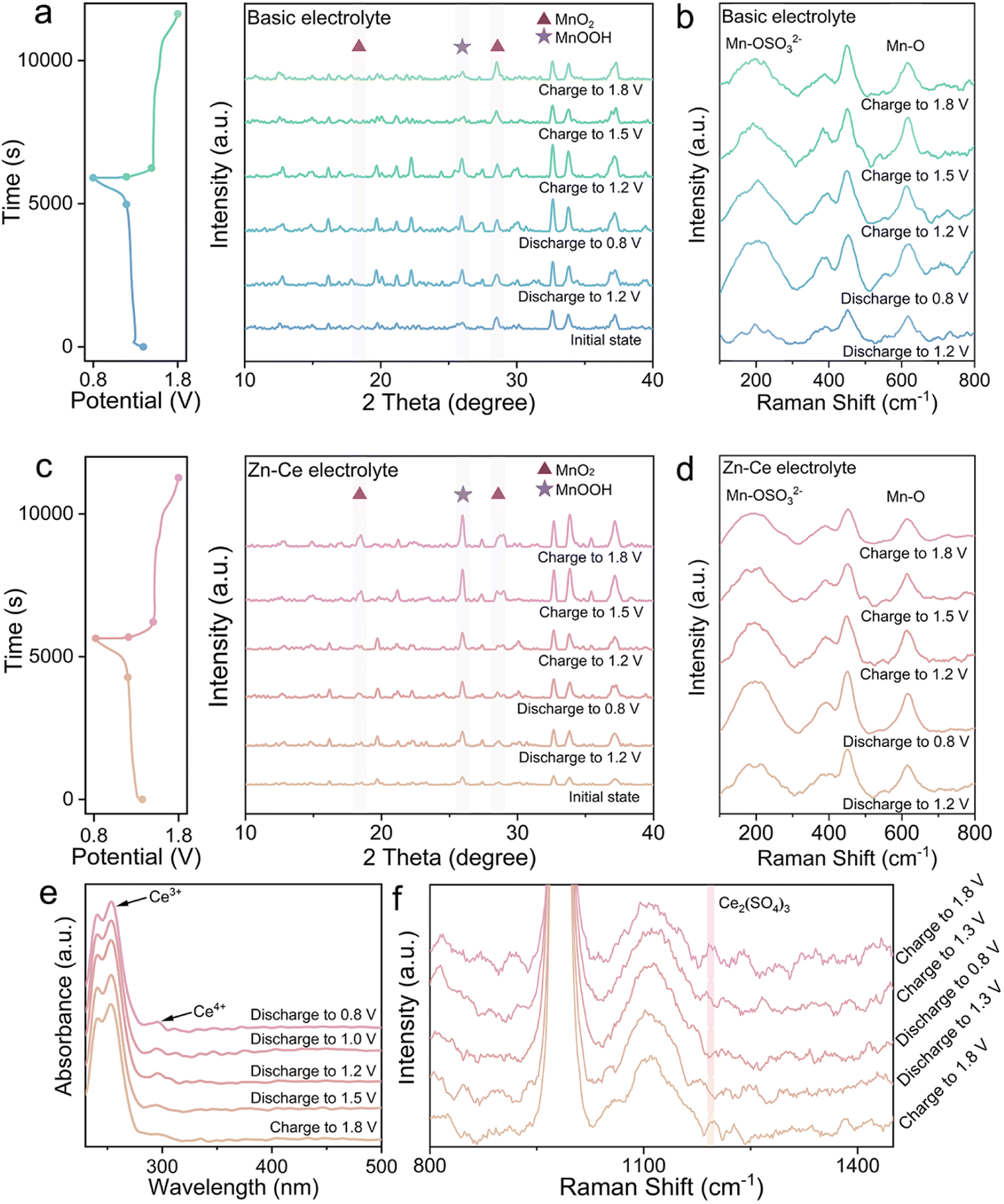 | ||
| Fig. 1 Investigation of the dynamic compensation mechanism. Ex situ (a) XRD patterns for the MnO2 cathodes and (b) Raman spectra for the electrolyte of the Zn/MnO2 battery with the basic electrolyte at different charge/discharge stages. Ex situ (c) XRD patterns for MnO2 cathodes and (d) Raman spectra for the electrolyte of the Zn/MnO2 battery with the Zn–Ce electrolyte at different charge/discharge stages. (e) UV-vis spectroscopy and (f) Raman spectra of the Zn–Ce electrolyte at different charge/discharge stages. | ||
For the Zn–Ce electrolyte, the increasing diffraction peaks of MnOOH on the cathode and decreasing peaks of Mn-OSO32− in the electrolyte were found during charging, which was not in accordance with eqn (1) (Fig. 1c and d). Addition of Ce(SO4)2 was considered to be the reason for this deviation, which was investigated further by ultraviolet-visible (UV-vis) spectroscopy. As shown in UV-vis and Raman spectra, periodic oscillation could be found for Ce3+ and Ce4+ (Fig. 1e and f).17,18 Based on these analytical results, the role of Ce4+ could be proposed as shown in eqn (2). With respect to the reaction, addition of Ce4+ is related to the redox couple for Mn2+. As mentioned above, the MnOOH generated during discharging tends to be converted to Mn2+ with the Jahn–Teller effect. During charging, parts of Mn2+ cannot return back to MnO2. Ce4+ can react with Mn2+ to form MnOOH via a redox reaction during charging. Subsequently, parts of MnOOH will deposit on the cathode by H+ attraction and transform further to MnO2 for participation in the electrochemical reaction on the cathode, which helps to increase the mass of active substances and enhance the capacity (Fig. 1c and S2†).
| Mn2+ + Ce4+ + 2H2O ↔ MnOOH + Ce3+ + 3H+ | (2) |
Furthermore, the Zn–Ce electrolyte was centrifugated and analyzed (Fig. 2). The peaks located at 882.6/886.6 eV and 883.0 eV in the high-resolution XPS Ce 3d spectrum for the Zn–Ce electrolyte represented Ce4+ and Ce3+, respectively. The peaks located at 642.5/653.9 eV and 643.1/655.0 eV in the high-resolution XPS Mn 2p spectrum for the sediment represent Mn3+ and Mn2+, respectively (Fig. 2a).19–23 Furthermore, the lattice-oxygen Mn–O–Mn and surface-adsorbed oxygen Mn–O–H also confirmed the generation of MnOOH.24 The XRD pattern showed that the sediment was mainly MnOOH (space group: Pbnm, JCPDS card number: 01-089-2354) (Fig. 2b). Moreover, the obvious co-existing signals of Ce4+ and Ce3+ demonstrated the reversibility of the Ce4+/Ce3+ conversion reaction (Fig. 2c). Combined with the oscillation of Ce3+/Ce4+ and Mn2+/MnOOH, we speculated that eqn (2) was reversible. That is, the decline of Ce3+ upon discharge was related to negative eqn (2), consistent with the increase in Ce4+ and Mn2+ (Fig. 1d and f). Moreover, the increase in Ce4+ and decrease in Ce3+ were shown by UV-vis spectroscopy, which was related to the reaction between Ce3+ and MnOOH during discharge (Fig. 1e). During discharge, the reaction between Ce3+ and MnOOH would be competitive, with the disproportionation of MnOOH, which would be beneficial for the Ce4+/Ce3+ reversible conversion reaction, and the opposite process would be found simultaneously. Herein, Hess's law can be introduced to explain this phenomenon (see ESI Discussion†). The change in Mn2+ and MnOOH with eqn (1) is the driving force of eqn (2). Based on this interpretation, the assumption that positive eqn (2) is influenced by the peak content of Mn2+ in the electrolyte at the termination of discharge is reasonable. The Mn content stayed about the same after one cycle because the balance of Ce4+/Ce3+ is obtained and negative eqn (2) competes with the disproportionation of MnOOH (Fig. S1†). As a result, stronger peaks of MnOOH can be found after 10 cycles, which is caused by the addition of Ce4+ (Fig. S3†). At the beginning of the cycle, positive eqn (2) is stronger due to the amount of Ce4+, whereas the balance is built later (Fig. 2c). Moreover, the variation in Mn at the cathode was studied by X-ray fluorescence (XRF) spectrometry (Fig. S4†). The mass of Mn was ∼45% after 50 cycles compared with the first cycle in the basic electrolyte, whereas it was 84% in the Zn–Ce electrolyte, showing that the dynamic compensation mechanism could inhibit the dissolution of Mn effectively. In summary, Mn2+ generated from the disproportionation of MnOOH during discharge was reconverted to MnOOH with the addition of Ce4+ during charging. MnOOH would deposit on the cathode by H+ attraction and be converted to MnO2 for capacity compensation during charging. Meanwhile, during discharge, Ce3+ would react with MnOOH and be converted to Ce4+ to achieve dynamic reversible Ce4+/Ce3+ conversion (Fig. 2d).
 | ||
| Fig. 2 Characterization of the results in the Zn–Ce electrolyte. (a) High-resolution X-ray photoelectron spectroscopy (XPS) of Ce 3d, Mn 2p, and O 1s of the Zn–Ce electrolyte. (b) XRD pattern of the sediment in the Zn–Ce electrolyte. (c) UV-vis spectroscopy of the Zn–Ce electrolyte in different cycles. (d) Dynamic compensation mechanism for the Zn/MnO2 battery with the Zn–Ce electrolyte (schematic). | ||
The scanning electron microscope (SEM) images, corresponding mapping images, and energy dispersive spectroscopy (EDS) of MnO2 cathodes upon discharging to 0.8 V and charging to 1.8 V revealed that the structures of MnO2 in the two types of electrolytes were distinct (Fig. S5–S7†). The concentration of Zn, O, and S suggested that Zn4SO4(OH)6·4H2O appeared on the MnO2 cathode in the basic electrolyte (Fig. S6†).25 During discharge, the increasing OH− in the electrolyte was the result of positive eqn (1), and reacted with Zn2+ and SO42− on the cathode to form Zn4SO4(OH)6·4H2O, which corresponded to the cathode in the basic electrolyte (Fig. S5a†). In contrast, the cathode surface in the Zn–Ce electrolyte was mainly MnOOH instead of Zn4SO4(OH)6·4H2O because OH− was likely to react with the extra H+ generated in eqn (2) rather than Zn2+ and SO42− (Fig. S7 and S8†).
Cyclic voltammetry (CV) at scan rates from 0.1 to 1 mV s−1 was performed to investigate the electrochemistry of Zn/MnO2 batteries with the Zn–Ce electrolyte (Fig. 3a). As reported previously, the scan (v) and peak current (i) can be used to analyze the contribution of diffusive-controlled and capacitive-controlled effects based on eqn (3) and (4).26,27
| i = avb | (3) |
log(i) = b![[thin space (1/6-em)]](https://www.rsc.org/images/entities/char_2009.gif) log(v) + log(a) log(v) + log(a) | (4) |
| i = k1v + k2v0.5 | (5) |
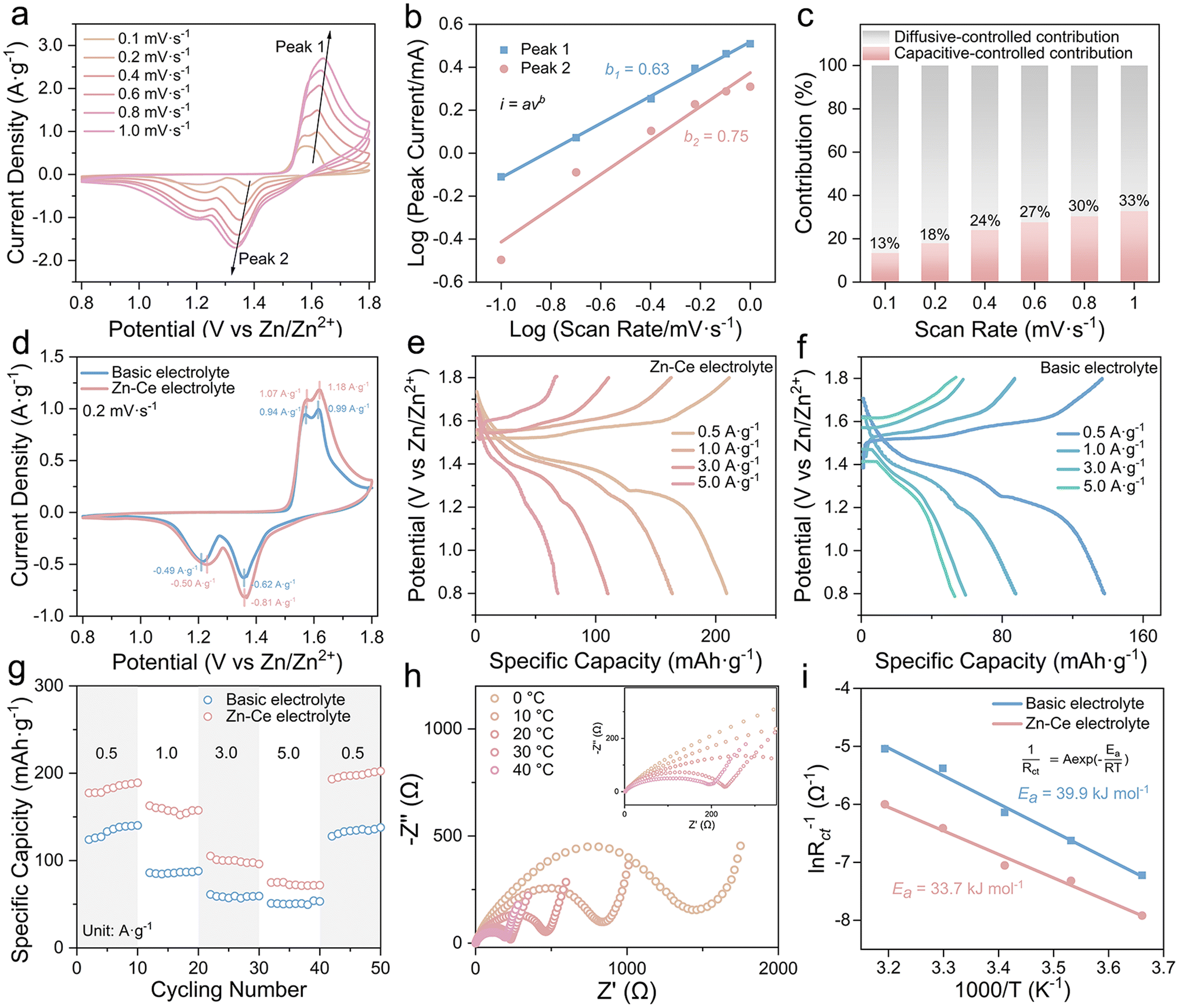 | ||
| Fig. 3 Electrochemical performance of the Zn/MnO2 battery. (a) CV curves at various scan rates from 0.1 to 1.0 mV s−1, (b) relationship between log(i) and log(v) plot at corresponding redox peaks, and (c) capacitive contribution ratio of the Zn/MnO2 battery with the Zn–Ce electrolyte. (d) CV curves of the Zn/MnO2 battery with the Zn–Ce electrolyte and basic electrolyte at 0.2 mV s−1. (e and f) Charge/discharge curves and (g) rate performance of Zn/MnO2 batteries with the basic electrolyte and Zn–Ce electrolyte at different current densities. (h) EIS curves of Zn/MnO2 batteries with the Zn–Ce electrolyte at different temperatures. (i) Activation energy (Ea) values of Zn/MnO2 batteries with the basic electrolyte and Zn–Ce electrolyte. | ||
The two peak-current values were utilized as the i values in eqn (3) and (4), and the linear relationship between log(i) and log(v) is shown in Fig. 3b. The corresponding b1 and b2 values of peaks were 0.63 and 0.75, respectively.28 Furthermore, the capacitive contribution ratio could be calculated using eqn (5). The result showed that the electrochemical behavior of the Zn/MnO2 battery with the Zn–Ce electrolyte was dominated by a diffusive-controlled contribution (Fig. 3c).29
According to the CV curves at 0.2 mV s−1 (Fig. 3d), one pair of redox peak corresponding to the MnO2/MnOOH conversion reaction could be found in the Zn/MnO2 battery with two types of electrolytes, which was consistent with the charge/discharge plateaus in galvanostatic charge/discharge curves (GCDs).30–32 Meanwhile, the higher current density of Zn/MnO2 batteries with Ce(SO4)2 additives in comparison with that without Ce(SO4)2 additives indicated a higher specific capacity, which was ascribed to the dynamic compensation mechanism (Fig. 3e–g).33 Therefore, the Zn/MnO2 battery with the Zn–Ce electrolyte exhibited a reversible capacity of 190.4 mA h g−1 at 0.5 A g−1 and maintained 105.2 mA h g−1 at 3 A g−1, and the capacity returned to 202.4 mA h g−1 when the current density returned to 0.5 A g−1 after 40 cycles, thereby demonstrating outstanding cycling stability (Fig. 3f). The charge-transfer resistance of the Zn/MnO2 battery with the Zn–Ce electrolyte at 30 °C was 217 Ω, which was far lower than that of the Zn/MnO2 battery with the basic electrolyte (608.6 Ω), indicating faster charge-transfer kinetics (Table S1†). Compared with the higher activation energy of the Zn/MnO2 battery with the basic electrolyte (39.9 kJ mol−1), that of the Zn/MnO2 battery with Zn–Ce electrolyte was lower (33.7 kJ mol−1), thereby indicating better reaction kinetics and resulting in a satisfactory rate performance (Fig. 3h–i and S9†). The lower Rct of the Zn/MnO2 battery with the Zn–Ce electrolyte at different cycles was attributed to the accelerated kinetics process shown above. Furthermore, accelerated kinetics at the anode was also shown with activation energy using electrochemical impedance spectroscopy (EIS) at different temperatures (Fig. S10 and Table S2†).30
Fig. 4 shows a comparison of the electrochemical performance of Zn/MnO2 batteries. The Rct changes of Zn/MnO2 batteries with the basic electrolyte and Zn–Ce electrolyte were studied (Fig. 4a, S11 and S12†). With an increase in shelf time, Zn/MnO2 batteries with the Zn–Ce electrolyte exhibited a much slower Rct growth compared with Zn/MnO2 batteries with the basic electrolyte, denoting better stability for storage. Moreover, this phenomenon was confirmed by the impendence–time curves of the Zn/MnO2 battery with the basic electrolyte and Zn–Ce electrolyte at 1000 Hz (Fig. S13†). Meanwhile, the Zn/MnO2 battery with the Zn–Ce electrolyte delivered greater capacity retention after 200 cycles at different temperatures, indicating superior wide-temperature stability (Fig. 4b and S14†). Furthermore, benefiting from the dynamic compensation of MnOOH, the Zn/MnO2 battery with the Zn–Ce electrolyte achieved reversible capacity retention of 97.4% and a capacity of 130.1 mA h g−1 at 1 A g−1 after 1000 cycles (vs. 40.5% and 75.8 mA h g−1 for the Zn/MnO2 battery with the basic electrolyte), and identical results were obtained at a current density of 0.5 A g−1 (Fig. 4c and d). It also had greater capacity retention compared with the partial Zn/MnO2 battery based on different optimization methods (Fig. 4e and Table S3†).34–40
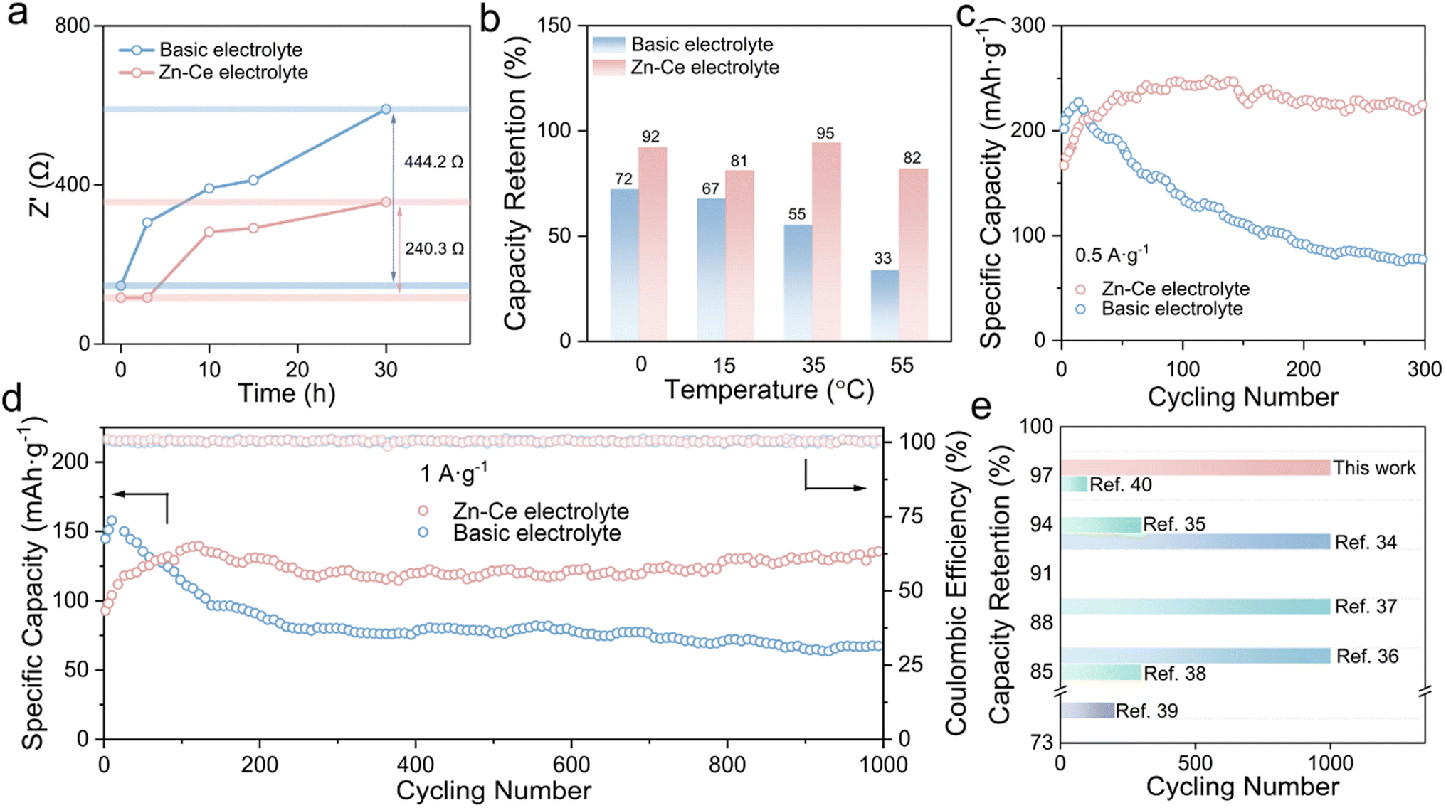 | ||
| Fig. 4 Comparison of the electrochemical performance of Zn/MnO2 batteries. (a) Changes in Rct values of Zn/MnO2 batteries with the basic electrolyte and Zn–Ce electrolyte during 30 h at room temperature. (b) Capacity retention of Zn/MnO2 batteries with the basic electrolyte and Zn–Ce electrolyte after 200 cycles at 0, 15, 35, and 55 °C. (c and d) Long cycling performance of Zn/MnO2 batteries with the basic electrolyte and Zn–Ce electrolyte at 0.5 and 1.0 A g−1. (e) Comparison of electrochemical performance of the Zn/MnO2 battery based on the Zn–Ce electrolyte with other Zn/MnO2 batteries reported previously.34–40 | ||
3 Conclusions
The Zn–Ce electrolyte was prepared to enhance the capacity retention of Zn/MnO2 batteries. The dynamic compensation mechanism was proposed to mitigate the disproportionation of MnOOH. Mn2+ formed from the disproportionation of MnOOH during discharging diffused into the electrolyte. Introduction of Ce4+ led it to react with part of Mn2+ to form MnOOH, which deposited partly on the cathode via the attraction of H+, and subsequently transformed to MnO2 during charging to dynamically compensate the active substance. Meanwhile, during discharge, Ce3+ reacted with MnOOH to reversibly convert to Ce4+, which inhibited the disproportionation of MnOOH. Benefiting from this strategy, Zn/MnO2 batteries with Ce(SO4)2 additives showed a capacity retention of 97.4% at 1.0 A g−1 after 1000 cycles, which far exceeded that of the Zn/MnO2 battery without Ce(SO4)2 additives.Author contributions
J. Z. and Y. T. conceived and supervised the research. G. L. and P. R. carried out the experiments and analysed the experimental data. B. L., S. L., and X. H. helped with the analysis of electrochemical data. All authors commented on the manuscript.Conflicts of interest
There are no conflicts of interest to declare.Acknowledgements
This work was supported by the National Natural Science Foundation of China (52172263, 51932011), Natural Science Foundation of Hunan Province (2022JJ30051), Hunan Natural Science Fund for Distinguished Young Scholar (2021JJ10064), and Program of Youth Talent Support for Hunan Province (2020RC3011).Notes and references
- Z. Xing, G. Xu, J. Han, G. Chen, B. Lu, S. Liang and J. Zhou, Trends Chem., 2023, 5, 380–392 CrossRef CAS.
- R. Yi, X. Shi, Y. Tang, Y. Yang, P. Zhou, B. Lu and J. Zhou, Small Struct., 2023, 2300020 CrossRef.
- W. Nie, H. Cheng, Q. Sun, S. Liang, X. Lu, B. Lu and J. Zhou, Small Methods, 2023, 2201572 CrossRef PubMed.
- S. Chen, K. Li, K. S. Hui and J. Zhang, Adv. Funct. Mater., 2020, 30, 2003890 CrossRef CAS.
- J. Ding, Z. Du, L. Gu, B. Li, L. Wang, S. Wang, Y. Gong and S. Yang, Adv. Mater., 2018, 30, 1800762 CrossRef PubMed.
- Y. Lu, T. Zhu, W. van den Bergh, M. Stefik and K. Huang, Angew. Chem., Int. Ed., 2020, 59, 17004–17011 CrossRef CAS PubMed.
- X. Chen, P. Ruan, X. Wu, S. Liang and J. Zhou, Acta Phys.-Chim. Sin., 2022, 38, 2111003 Search PubMed.
- E. Faegh, T. Omasta, M. Hull, S. Ferrin, S. Shrestha, J. Lechman, D. Bolintineanu, M. Zuraw and W. E. Mustain, J. Electrochem. Soc., 2018, 165, A2528–A2535 CrossRef CAS.
- G. Yang, Q. Li, K. Ma, C. Hong and C. Wang, J. Mater. Chem. A, 2020, 8, 8084–8095 RSC.
- H. Pan, Y. Shao, P. Yan, Y. Cheng, K. S. Han, Z. Nie, C. Wang, J. Yang, X. Li, P. Bhattacharya, K. T. Mueller and J. Liu, Nat. Energy, 2016, 1, 16039 CrossRef CAS.
- B. Wu, G. Zhang, M. Yan, T. Xiong, P. He, L. He, X. Xu and L. Mai, Small, 2018, 14, 1703850 CrossRef PubMed.
- Q. Ren, Y. Yuan and S. Wang, ACS Appl. Mater. Interfaces, 2022, 14, 23022–23032 CrossRef CAS PubMed.
- J. Yang, J. Cao, Y. Peng, W. Yang, S. Barg, Z. Liu, I. A. Kinloch, M. A. Bissett and R. A. W. Dryfe, ChemSusChem, 2020, 13, 4103–4110 CrossRef CAS PubMed.
- N. Zhang, F. Cheng, J. Liu, L. Wang, X. Long, X. Liu, F. Li and J. Chen, Nat. Commun., 2017, 8, 405 CrossRef PubMed.
- Q. Dai, L. Li, B. Hu, Y. Jia, T. Tu, T. K. A. Hoang, M. Zhang and L. Song, Mater. Today Commun., 2022, 31, 103578 CrossRef CAS.
- Z. Liu, Y. Yang, B. Lu, S. Liang, H. J. Fan and J. Zhou, Energy Storage Mater., 2022, 52, 104–110 CrossRef.
- W. J. Jeon, H. Kim and S. H. Byeon, Colloids Surf., A, 2022, 640, 128416 CrossRef CAS.
- R. Flouty, E. AbiAad, S. Siffert and A. Aboukaïs, J. Therm. Anal. Calorim., 2003, 73, 727–734 CrossRef CAS.
- J. Chen, W. Shi and J. Li, Catal. Today, 2011, 175, 216–222 CrossRef CAS.
- M. Chang, J. Wu, D. Chen and S. Ye, Corros. Sci. Technol., 2018, 17, 1–5 CAS.
- L. Gong, R. Tang, Y. Zhu and D. Chen, Int. J. Miner., Metall. Mater., 2012, 19, 800–804 CrossRef CAS.
- B. R. Strohmeier and D. M. Hercules, J. Phys. Chem. C, 1984, 88, 4922–4929 CrossRef CAS.
- Y. Wang, L. Chen, M. Chen, Z. Zhong, Q. Meng and W. Xing, Sci. China Mater., 2019, 62, 527–535 CrossRef CAS.
- Y. O. Yesilbag, F. N. Tuzluca and M. Ertugrul, J. Mater. Sci.: Mater. Electron., 2019, 30, 8201–8209 CrossRef CAS.
- X. Guo, J. Zhou, C. Bai, X. Li, G. Fang and S. Liang, Mater. Today Energy, 2020, 16, 100396 CrossRef.
- W. Yang, W. Yang, Y. Huang, C. Xu, L. Dong and X. Peng, Chin. Chem. Lett., 2022, 33, 4628–4634 CrossRef CAS.
- Y. Li, P. Wu, W. Zhong, C. Xie, Y. Xie, Q. Zhang, D. Sun, Y. Tang and H. Wang, Energy Environ. Sci., 2021, 14, 5563–5571 RSC.
- Y. Liu, S. Liu, X. Xie, Z. Li, P. Wang, B. Lu, S. Liang, Y. Tang and J. Zhou, InfoMat, 2023, 5, e12374 CAS.
- Z. Pan, J. Yang, J. Yang, Q. Zhang, H. Zhang, X. Li, Z. Kou, Y. Zhang, H. Chen, C. Yan and J. Wang, ACS Nano, 2020, 14, 842–853 CrossRef CAS.
- X. Xie, J. Li, Z. Xing, B. Lu, S. Liang and J. Zhou, Natl. Sci. Rev., 2023, 10, nwac281 CrossRef PubMed.
- Y. Song, P. Ruan, C. Mao, Y. Chang, L. Wang, L. Dai, P. Zhou, B. Lu, J. Zhou and Z. He, Nano-Micro Lett., 2022, 14, 218 CrossRef CAS PubMed.
- X. Cai, Y. Liu, J. Zha, F. Tan, B. Zhang, W. Yan, J. Zhao, B. Lu, J. Zhou and C. Tan, Adv. Funct. Mater., 2023, 2303009 CrossRef.
- H. Chen, S. Cai, Y. Wu, W. Wang, M. Xu and S. J. Bao, Mater. Today Energy, 2021, 20, 100646 CrossRef CAS.
- Z. Shen, Z. Tang, C. Li, L. Luo, J. Pu, Z. Wen, Y. Liu, Y. Ji, J. Xie, L. Wang, Y. Yao and G. Hong, Adv. Energy Mater., 2021, 11, 2102055 CrossRef CAS.
- Y. Zeng, X. Zhang, Y. Meng, M. Yu, J. Yi, Y. Wu, X. Lu and Y. Tong, Adv. Mater., 2017, 29, 1700274 CrossRef.
- H. Tang, W. Chen, N. Li, Z. Hu, L. Xiao, Y. Xie, L. Xi, L. Ni and Y. Zhu, Energy Storage Mater., 2022, 48, 335–343 CrossRef.
- J. Gao, X. Xie, S. Liang, B. Lu and J. Zhou, Nano-Micro Lett., 2021, 13, 69 CrossRef.
- J. Yang, G. Yao, Z. Li, Y. Zhang, L. Wei, H. Niu, Q. Chen and F. Zheng, Small, 2023, 19, 2205544 CrossRef CAS.
- L. C. Dong, Y. B. Zhong, S. Zhe, T. Y. Zheng and H. Wang, RSC Adv., 2016, 6, 21037–21042 RSC.
- S. Islam, M. H. Alfaruqi, V. Mathew, J. Song, S. Kim, S. Kim, J. Jo, J. P. Baboo, D. T. Pham, D. Y. Putro, Y.-K. Sun and J. Kim, J. Mater. Chem. A, 2017, 5, 23299–23309 RSC.
Footnotes |
| † Electronic supplementary information (ESI) available. See DOI: https://doi.org/10.1039/d3ta02202a |
| ‡ These authors contributed equally to the work. |
| This journal is © The Royal Society of Chemistry 2023 |