
 Open Access Article
 This Open Access Article is licensed under a
 Creative Commons Attribution 3.0 Unported Licence
Neutron and muon characterisation techniques for battery materials
Gabriel E.
Pérez
 ab,
Jake M.
Brittain
ab,
Innes
McClelland
bc,
Stephen
Hull
ab,
Martin O.
Jones
ab,
Helen Y.
Playford
ab,
Serena A.
Cussen
bc,
Peter J.
Baker
ab and
Emily M.
Reynolds
*ab
ab,
Jake M.
Brittain
ab,
Innes
McClelland
bc,
Stephen
Hull
ab,
Martin O.
Jones
ab,
Helen Y.
Playford
ab,
Serena A.
Cussen
bc,
Peter J.
Baker
ab and
Emily M.
Reynolds
*ab
aISIS Neutron and Muon Source, Rutherford Appleton Laboratory, Harwell Science and Innovation Campus, Didcot, UK. E-mail: emily.reynolds@stfc.ac.uk
bThe Faraday Institution, Quad One, Harwell Science and Innovation Campus, Didcot, UK
cDepartment of Materials Science and Engineering, The University of Sheffield, Sheffield, UK
First published on 29th March 2023
Abstract
Neutron and muon characterisation techniques offer unique capabilities for investigating the complex structure and dynamics of rechargeable battery systems. Whilst the non-monotonic interaction of the neutron with the nuclei of atoms makes it sensitive to light and neighbouring elements in the periodic table, its weakly interacting nature allows it to penetrate deep into the sample without damaging it, enabling the flexible use of complex sample environments such as in situ/in operando cells. Meanwhile, the also non-invasive nature of an implanted positive muon allows it to be used as a probe to study bulk ionic diffusion phenomena within materials at different depths by tuning the energy of the incident muons. This review discusses the application of relevant neutron and muon characterisation techniques to the study of specific phenomena in ion batteries, highlighting key literature cases that serve as the archetypal example for the utility of each technique. Furthermore, this review includes an accessible overview of the working principles of each technique that has been condensed and optimised to provide a basic understanding of their relevance to the particular challenges they can address.
1 Alkali-ion batteries
The 2019 Nobel Prize in Chemistry was awarded to John B. Goodenough, M. Stanley Whittingham and Akira Yoshino for their work on the development of lithium-ion (Li-ion) batteries in 1980, creating a “rechargeable world”.1 In 1991, Sony commercialised the first Li-ion battery, which accelerated their wide-spread use. Today, Li-ion technology can be found in a range of devices, such as mobile phones, laptops, battery electric vehicles and stationary energy storage systems. However, with the demand for rechargeable battery technology on the rise and the shift in focus to green sustainability, Li-ion technology cannot be the sole solution, and characterisation is the key to unlocking new, more environmentally conscious technologies.2,3 For instance, sodium-ion (Na-ion) can be a complementary technology to Li-ion, and more sustainable as sodium is much more abundant than lithium.4 Na-ion technology can help total battery technology supply meet demand; for example Na-ion is perfectly suited to short-term stationary grid storage, where sustainability and low-cost are more important than energy density.Be it new Li/Na-ion materials, or components used in other battery technologies such as Mg-ion, Li–S, or Li-air, the challenges associated with characterisation of the structure and dynamics in the battery components and the whole are non-trivial. This review highlights the ways in which neutron and muon techniques can address the characterisation challenges of alkali-ion batteries, specifically Li and Na due to the research involving these technologies, however the techniques are more widely applicable to general energy storage materials. This section provides the reader with an introduction to the battery terminology and chemistry that is covered in the main text of this review paper, followed by a discussion highlighting the relevant advantages of neutrons and muons as characterisation probes.
1.1 Typical anatomy and electrochemistry of a Li/Na-ion cell
A Li/Na-ion cell primarily consists of a cathode, an anode, and an electrolyte (Fig. 1). To complete a cell, a separator, current collectors, and casing are also required. The separator is a micro-porous material that is positioned between the cathode and anode to prevent short-circuiting, but allowing the diffusion of Li/Na-ions through the liquid electrolyte. The current collectors connect the electrodes to the external electrical circuit. They should be cheap and excellent electrical conductors. Na-ion cells typically use aluminium at both electrodes. Li-ion cells require a more expensive copper current collector at the anode due to the detrimental alloy reactions associated with lithium and aluminium. All components of the cell are carefully compressed together, and typically cased in either coin cells, pouch cells, or cylindrical (e.g. 18![[thin space (1/6-em)]](https://www.rsc.org/images/entities/char_2009.gif) 650) cells.
650) cells.
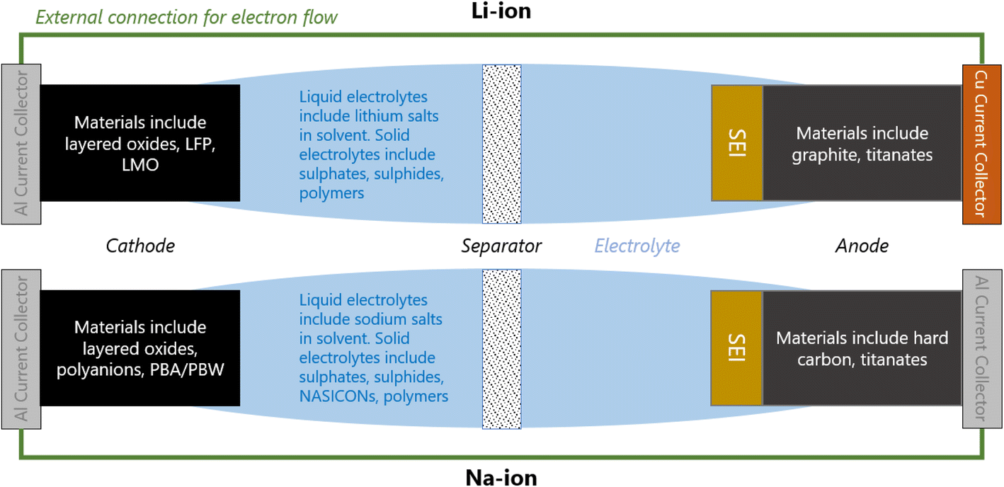 | ||
| Fig. 1 Schematic of a typical: (Top) Li-ion cell; (Bottom) Na-ion cell. | ||
When a positive current is applied across the electrodes, the cell begins charging; Li/Na-ions deintercalate from the cathode, diffuse through the electrolyte and insert into the anode. In order to maintain charge neutrality in the cathode, the redox-active metals undergo oxidation, losing one electron to the current collector per Li/Na-ion that deintercalates. The electrons flow around the electrical circuit and reduce the anode. When the cell is in use (discharging), the reverse processes take place.
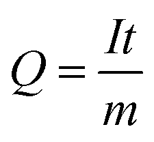
The capacity of a cell is related to the number of Li/Na-ions that are shuttled between the cathode and anode during one full charge–discharge cycle. The specific capacity, Q, typically measured in mA h g−1, is given by
| E = ∫VdQ |
The C-rate indicates how fast a cell is being cycled and is normalised to its maximum capacity to facilitate comparison between different systems – a cell cycling at 1 C will perform a half-cycle in 1 h.
1.2 Cathode materials
In the pristine state, the cathode material is typically Li/Na-ion rich, containing redox-active metals. It is vital the cathode provides facile diffusion of the Li/Na-ions and has good electrical conductivity. A high working voltage is targeted vs. Li/Li+ (or Na/Na+) to increase the average cell voltage.Goodenough et al. discovered the LixCoO2 cathode material in 1980.5 It adopts a layered structure with octahedrally coordinated Li-ions between the CoO6 layers (Fig. 2, left). This structure was revolutionary and forms the basis of many cathode materials today. LiNixMnyCozO2 (NMC) and LiNixCoyAlzO2 (NCA) are high-energy Li-ion cathode materials, used extensively in commercial applications. They adopt the same layered structure as LixCoO2.
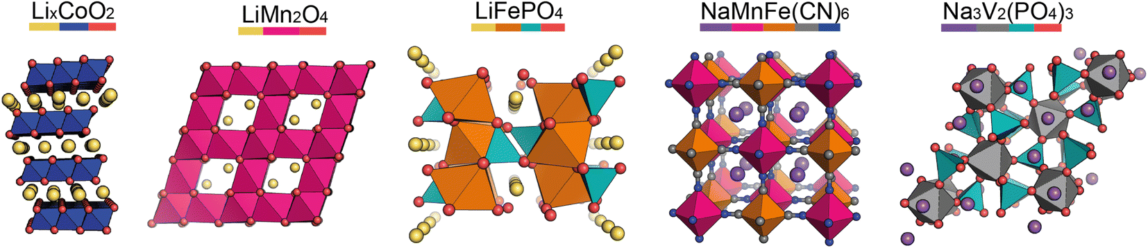 | ||
| Fig. 2 Structures of the key cathode materials covered in this review. Left to right: layered oxide (which NMC, NCA, and the Na-ion P2 and O3 materials are based on), LMO, LFP, PBA, NASICON. Element colours are shown by the coloured bar under the formulae. | ||
Other common Li-ion cathode materials, displayed in Fig. 2, include lithium iron phosphate, LiFePO4 (LFP), and lithium manganese oxide, LiMn2O4 (LMO). LFP adopts the olivine structure with a hexagonally close-packed oxygen array, the 1D channels through the structure allow facile Li-ion diffusion leading to a high power output. The structure is stable on cycling—only a slight expansion/contraction on charging/discharging—leading to a very long cycle life. Thackeray et al. discovered the application of LMO as a cathode material in 1983.6 It adopts a spinel structure, with 3D Li-ion diffusion. Typically it has better energy density than LFP, but the cycle life is poorer.
For Na-ion cathode materials, three cathode structure types dominate the literature: layered oxides, Prussian blue/white analogues (PBAs/PBWs) and polyanionics. Each have their advantages and disadvantages for commercial applications. For high energy applications, layered oxides are leading the way. Due to the larger size of Na-ions compared to Li-ions, the coordination geometry of Na-ions in these materials are elongated octahedral or trigonal prismatic, leading to two common phase sub-groups, O and P.7 O3 materials have high sodium-stoichiometries, ideal for high energy applications,8 whereas P2 materials have better Na diffusion resulting in higher power densities than O3 materials.9
PBAs have the general formula NaM[Fe(CN)6] and form in a perovskite-type cubic structure. PBAs typically have a high working voltage, are low-cost, and have long cycle lives.10 Polyanionics typically exhibit stable host frameworks for Na-ion diffusion. NASICON-type phosphates are the most common, displaying superior ionic conductivity due to their 3D open frameworks (Fig. 2, right).11 The best known Na-ion NASICON material has the formula Na3V2(PO4)2F3.12 Two sodium sites are present in the structure, but only Na-ions in one of the sites can be reversibly extracted, resulting in a low capacity.
When designing novel battery technologies, energy density, power density, and cycling stability are all crucial properties to enhance. The energy densities of typical cathode materials are an order of magnitude lower than typical anode materials, meaning they are the limiting factor. The ease of ionic mobility through the cathode structure contributes to power density, but studying bulk ionic diffusion can be challenging as the common techniques such as EIS and GITT are dependant on sample preparation and morphology, whereas NMR can be difficult for materials containing magnetic ions such as cobalt. Furthermore, phase changes or Li/Na-vacancy ordering on cycling can be detrimental to the cycle life of cathodes and understanding oxygen redox could enhance energy density. However, extracting Li or oxygen positions as well determining an atomic structure that involves multiple transition metals can be challenging using the most commonly available characterisation techniques such as those based on X-rays.
1.3 Anode materials
Pristine anode materials typically contain an open-framework structure in which Li/Na-ions can easily intercalate reversibly. Electrical conduction is equally important as in the cathode materials and the voltage of the anode material vs. Li/Li+ (or Na/Na+) should be low to increase the average cell voltage.Graphite-based anodes (Fig. 3, left) are deemed the standard anode for Li-ion batteries. Typically they are low-cost, with high energy densities due to their low de-/lithiation potentials (around 0.2 V vs. Li/Li+) and high gravimetric capacities. However, Li-ion intercalation into the graphite layers has a low diffusion rate associated with it, making the anode material non-ideal for high power applications.13 Na-ions cannot intercalate into graphite (without the help of co-intercalation solvents), so hard carbons are typically used.14,15 Hard carbon is a turbostratically disordered analogue of graphite, containing curvature within the layers (Fig. 3, third left to right). The intrinsic disorder and curvature creates pores and greater interlayer spacing, favouring the intercalation of Na-ions.
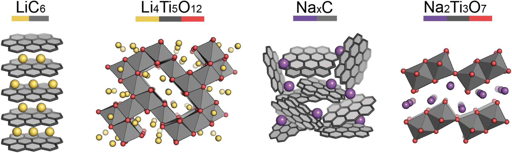 | ||
| Fig. 3 Structures of the key anode materials covered in this review. (Left to right) Graphite, lithium titanate, hard carbon, sodium titanate. Element colours are shown by the coloured bar under the formulae. | ||
Lithium titanate (Li4Ti5O12) adopts a spinel structure with space group Fd![[3 with combining macron]](https://www.rsc.org/images/entities/char_0033_0304.gif) m (Fig. 3, second left to right). During Li-ion intercalation on charging, this forms a rock salt structure, with minimal change in cell volume. This is advantageous as minimal crystal strain is induced on cycling, leading to superior cycling stability. Its high operating voltage limits SEI formation too, enabling high safety, however this reduces the working voltage and therefore cell energy density. Another drawback is its poor conductivity, however, at the time of writing research into lithium titanates is in its infancy. The sodium analogue, sodium titanate (Na2Ti3O7), exchanges Na-ions at very low voltages (0.3 V), which is its main advantage over hard carbon anodes.16 This material has a high capacity (200 mA h g−1), due to the intercalation of two sodium ions per formula unit. The characterisation challenges of anode materials are very similar to those of cathodes, but semi-amorphous materials, such as hard carbon, have the added complexity of characterising their porosities and disordered structures.
m (Fig. 3, second left to right). During Li-ion intercalation on charging, this forms a rock salt structure, with minimal change in cell volume. This is advantageous as minimal crystal strain is induced on cycling, leading to superior cycling stability. Its high operating voltage limits SEI formation too, enabling high safety, however this reduces the working voltage and therefore cell energy density. Another drawback is its poor conductivity, however, at the time of writing research into lithium titanates is in its infancy. The sodium analogue, sodium titanate (Na2Ti3O7), exchanges Na-ions at very low voltages (0.3 V), which is its main advantage over hard carbon anodes.16 This material has a high capacity (200 mA h g−1), due to the intercalation of two sodium ions per formula unit. The characterisation challenges of anode materials are very similar to those of cathodes, but semi-amorphous materials, such as hard carbon, have the added complexity of characterising their porosities and disordered structures.
1.4 Electrolyte
While liquid electrolytes are the most commonly used,17 research into novel solid electrolytes is growing due to their increased safety features.18 The electrolyte connects the cathode and anode, allowing diffusion of the Li/Na-ions between the two. It should be chemically inert to the cathode and anode materials, electrically insulating, and must be stable across the whole voltage range. A solid electrolyte interface (SEI) layer commonly forms on the first cycle by decomposition of the electrolyte onto the anode surface. It is an essential component of the cell, preventing further decomposition and maintaining cycling performance; however, SEI's must be controlled as they can be detrimental to ion diffusion and electrical conductivity.19While the active electrode materials set the energy output for the cell, the electrolyte is vital for ionic mobility. Typical electrolyte salts have inorganic anions based on a central atom with electronegative ligands withdrawing electron density to create a delocalised negative charge over the anion. This creates weakly coordinating cations-anions; perfect for ion mobility. Such anions are also more likely to be stable against oxidation, but the choice of salt affects the chemical and electrochemical stability. Examples of typical electrolyte salts are LiPF6, LiC2NO4F6S2 (LiTFSI), and NaPF6. Typical electrolyte solvents must be polar and have a low viscosity in order to dissolve the Li/Na-salt and facilitate ionic mobility. A large electrochemical stability window (ESW) is also essential—particularly the lower limit of the ESW as this dictates the lower limit of the electrolyte's ESW—meaning the solvents are always aprotic. Typical solvents include ethylene carbonate (EC), propylene carbonate (PC) and diethyl carbonate (DEC).
Solid-state electrolytes are intrinsically safer than liquid electrolytes, with the key challenge being the interface between the electrolyte and electrode. Typical materials include sulphates, sulphides, polymers and NASICONs. These electrolytes each bring their own characterisation challenges – for example polymers are disordered and contain light elements such as H. However, for electrolyte performance in general, the dynamics within the material, especially the Li/Na mobility, is most important. As mentioned, each technique has limitations, and to study their dynamic behaviour, complex experiments, such as in situ or operando, are needed.
Finally, the SEI has a large impact on the electrochemical performance, yet it is very difficult to study. Reasons for this include the many disordered components, that these components are buried interfaces, and that the SEI is usually not a stable structure but one that evolves during cycling. To characterise the SEI requires different probes, especially those that can measure its formation and evolution in operando. These and all the forementioned challenges require a holistic characterisation approach and a wide range of specialist techniques that can provide very specific information about any given battery system of interest.
2 Advantages of neutrons and muons for battery research
As described in the previous section, typical battery systems contain a plethora of intricacies at a wide range of length scales which must be understood to push forward the commercialisation of novel materials. The main challenges facing battery technologies are energy and power density, cycle life, cost, safety, environmental impact, and sustainability. Addressing the breadth of characterisation challenges involved in the development of next-generation battery systems requires the use of all available characterisation tools. Neutrons and muons can be used as characterisation probes offering unique capabilities to investigate various phenomena and properties of the different components in battery systems. This is summarised in Fig. 4 and the main reasons behind their advantageous use are briefly summarised here.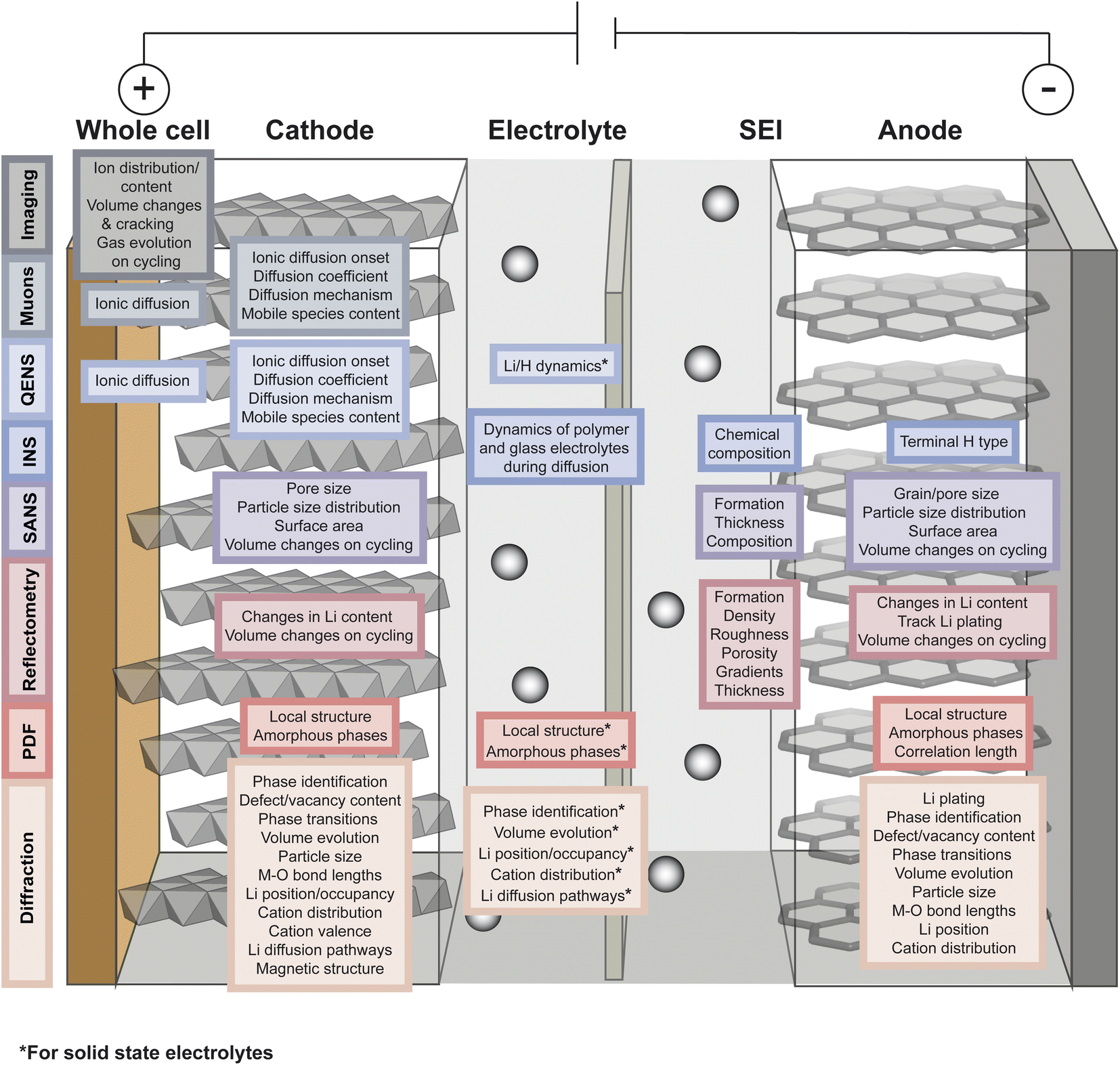 | ||
| Fig. 4 Overview of the capabilities of neutron and muon characterisation techniques for the study of the different components in rechargeable battery systems. | ||
The nuclear interaction of neutrons with a sample is not exclusively nor monotonically dependent on the number of neutrons, protons, or electrons in the atom. This means that neutrons can interact significantly with light elements such as hydrogen and lithium, as well as easily distinguish most neighbouring elements in the periodic table. These capabilities are more challenging to achieve using electron cloud-scattering probes such as electrons, X-rays, and other lower energy photons due to their monotonic dependence on atomic number. Modern X-ray scattering techniques can, to some extent, overcome these limitations, especially at synchrotrons where resonant X-ray scattering is available for almost all relevant transition metals. However, neutrons offer superior contrast for studies in which light or neighbouring elements are a subject of interest.
The nature of such interaction offers a couple of major advantages to battery research; firstly, the ability to distinguish between elements with a similar number of electrons is relevant for studying cathode materials that often contain a mixture of first row transition metals (TM). This applies to all techniques, but specifically neutron diffraction and total scattering which are used for characterising the long range or local TM distribution in electrodes and solid state electrolytes. On the other hand, the sensitivity of neutrons to light elements makes it possible to use them to study the usually low atomic number ions, such as Li, Na, and Mg, used in ion batteries. For instance, neutron diffraction can be used to extract the sites and occupancies, and thermal parameters of Li in the structure more easily than it would be with X-ray diffraction. Moreover, neutron reflectometry can be used to probe interfacial structures such as the SEI with high sensitivity to organic species, while and imaging techniques can probe Li distribution across an entire electrode or battery.
The nuclear dependence of neutron scattering also results in the possibility of two isotopes having substantially different scattering lengths. Therefore, using isotopic substitution it is possible to modify the neutron nuclear scattering length of samples for different purposes such as lowering the incoherent scattering of the sample, or labelling specific parts of a molecule to identify more easily their specific effect on the scattering spectrum.
Another important characteristic of the neutron as a probe is that it is relatively weakly interacting due to the very short range of the strong interaction. This renders the neutron as a highly penetrating probe enabling the investigation of the bulk of the sample rather than the just the surface. This is usually a limiting factor for electron cloud-interacting probes unless their energy is highly increased, and such highly energetic X-rays or electrons can damage the sample; in contrast, neutrons are a non-destructive probe due to their weak and non-electronic interactions with the sample. Moreover, the use of sample environments such as cryostats, pressure chambers, and furnaces is simpler since neutrons can easily penetrate through them, especially if their design includes specifically designed neutron-transparent windows. For batteries, this makes neutron scattering an excellent probe for operando experiments of bespoke or commercial cells. This includes, but is not limited to, diffraction experiments to understand the structural changes of electrodes, small angle neutron scattering (SANS) to observe the formation of the SEI and evolution of porous structures, and neutron imaging to observe changes in Li distribution and cell degradation, all during cycling in half or full cells.
The weak interaction of neutrons has one main disadvantage, which is arguably the main disadvantage of neutron characterisation techniques. This is that a high amount of neutron interactions are required to obtain meaningful data with sufficient statistical accuracy. Although neutron interactions can, to some extent, be increased by substituting some isotopes with others with a stronger nuclear scattering length, this is not always possible and it can only increase the detected neutron intensity by a limited amount. Other factors used to improve data quality are long measurement times and large sample sizes, neither of which are always convenient or good for time-resolved studies. In order to significantly increase the amount of neutron interactions, higher neutron fluxes are needed which are entirely dependant on the neutron source and instrumentation.
The final relevant unique characteristic of neutrons is their energy – thermal neutrons have energies within the energy range (μeV to eV) of atomic and electronic processes such as quantum tunneling, ionic diffusion, and lattice vibrations (phonons). This means that inelastic neutron scattering (INS) and quasi-elastic neutron scattering (QENS) experiments are able to probe these phenomena, providing insight into the dynamics of solid-state electrolytes that enable diffusion processes, and ionic diffusion mechanisms in electrodes, to name a few examples.
Muons possess intrinsic properties that allow them to be used in a unique way to study battery materials. Due to their charged nature, they can be implanted into a sample and held within through electrostatic forces. A positively charged muon usually stops at interstitial sites of high electron density such as the vicinity of O2− anions where its spin is altered by any magnetic moments that are in close proximity to the implanted muon. A unique characteristic of the muon is that after a couple of μs, it decays emitting a positron that critically conserves the spin of the muon at the time of decay. An analysis of such change in the muon's spin can be performed to determine intrinsic material properties, such as the diffusion coefficient, an activation energy for ionic motion, and the strength/proximity of local magnetic fields to the muon site, provided that the sample is adequately characterised structurally. For that reason, coupled with the convenience that both probes are usually produced in the same facilities, neutron and muon techniques can be highly complementary to each other, especially since both probes are highly penetrating and negligibly-damaging to the sample of interest. One example of this is their potential to study buried regions, such as the solid electrolyte interface, without inducing any significant effects on its highly sensitive chemistry. Another typical example of this complementary is the wide range of time scales at which dynamics can be studied by combining techniques such as quasielastic neutron scattering, 10−7 to 10−13 s, and muon spectroscopy, 10−5 to 10−8 s. An additional important advantage of muons is that their energy can be tuned to define the depth of implantation making it possible to study different regions within the bulk of a sample whilst ignoring the effects of any adjacent interface.
The next two sections will provide an overview of the different neutron and muon characterisation techniques that have been applied to battery research and discuss how they have been used to investigate the structural and dynamic properties of battery materials.
3 Neutron scattering
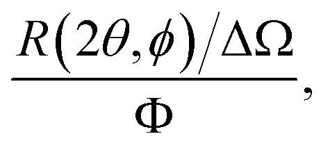
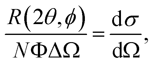
In a scattering experiment, the sample of interest is irradiated with a wave-behaving probe that has an incident wavevector, ki, and an incident frequency, ωi. After interacting with the sample, the probe emerges with a different wavevector, kf, and a different frequency, ωf. The information about the structure and dynamics of the sample is encoded within such wavevector and frequency changes, Q = ki − kf and ω = ωi − ωf, respectively. However, what is measured in a scattering experiment is the fraction of incident probing particles that emerge in different three-dimensional directions, defined by the angles θ and ϕ as shown in Fig. 5, after being scattered by the sample. This can be quantified as the rate of arrival of the scattered particles in a given direction, R(2θ, ϕ), into a detector that subtends an infinitesimally small solid angle ΔΩ from the sample, divided by the incident flux Φ:where the SI units of R(2θ, ϕ), ΔΩ, and Φ, are s−1, steradians (sr), and m−2 s−1, respectively. This quantity can be normalised against a desired scattering unit N such as atoms, molecules, kg, m3, etc. The resulting expression becomes:
 | (1) |
 , to study the spatial arrangement of matter in the sample. The derivative of the differential cross-section will yeld the double differential cross-section which can be measured as a function of both the wavevector and frequency change,
 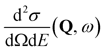 , to study the temporal arrangement of matter in the sample. Most of the scattering techniques discussed in this review focus exclusively on the measurement and analysis of elastic scattering in which there is no change in energy between the incident and scattered particle, i.e. ω = ωi − ωf = 0. In such case, the magnitude of the wavevector change can be derived from vector geometry in Fig. 5 as:
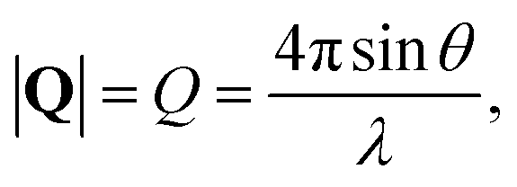 | (2) |
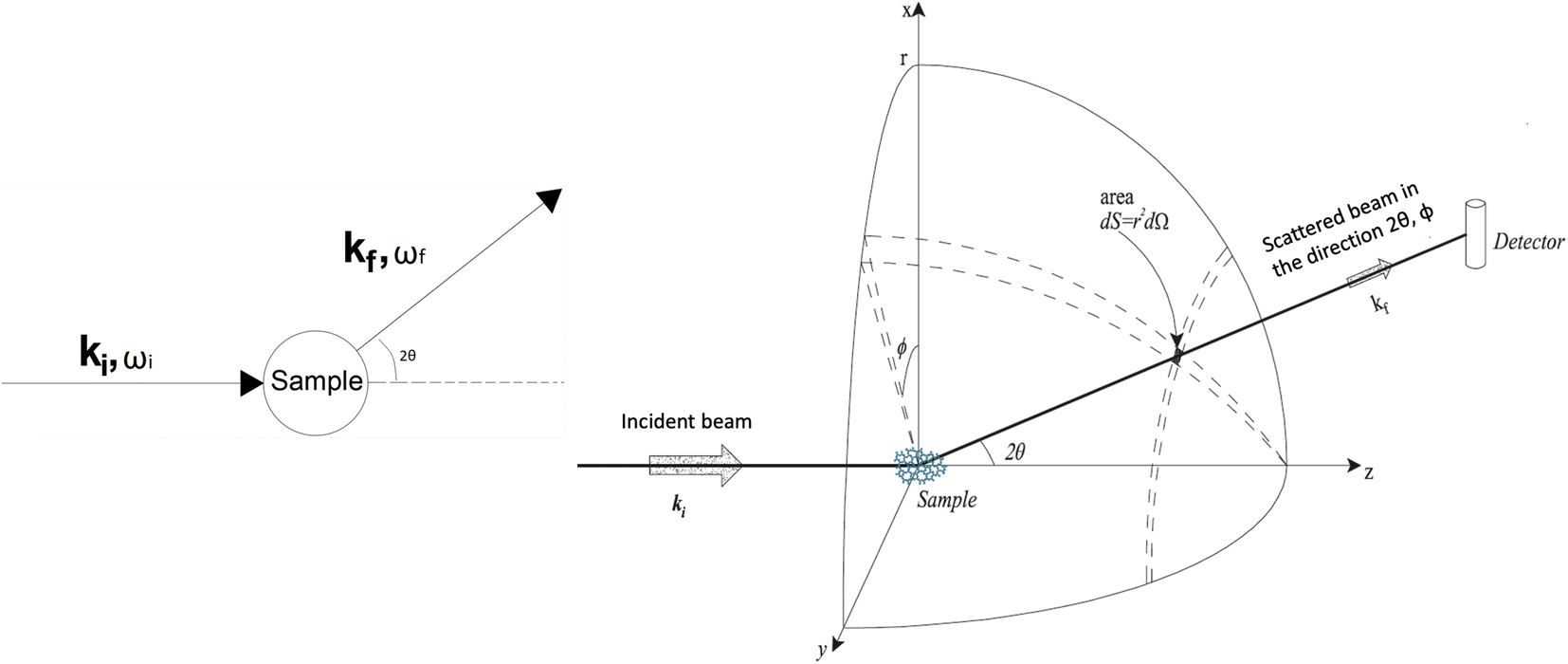 | ||
| Fig. 5 (Left) Vector representation of a particle scattered by a sample. (Right) Geometry for a scattering experiment. Reproduced with permission from ref. 20. Copyright 2016, Elsevier Ltd. | ||
This differential cross-section is proportional to the atomic scattering factor, 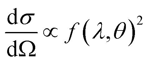 , which is dependent on the atomic composition of the scatterer, but also on the type of scattering probe used.
Neutrons can interact with the nucleus of an atom via the strong force, and with the dipole moments of the sample's constituents via the neutron's spin. Nucleus-interacting neutrons are known as thermal neutrons, and their wavelength (∼10−10 m) is significantly bigger than their interaction range with the nucleus (∼10−14 m). This results in the nucleus behaving as a point scatterer; and thus, the scattering being isotropic. This means that the neutron's nuclear scattering factor is independent from θ and ϕ, and therefore
| f(θ, λ) = −b, |
 | (3) |
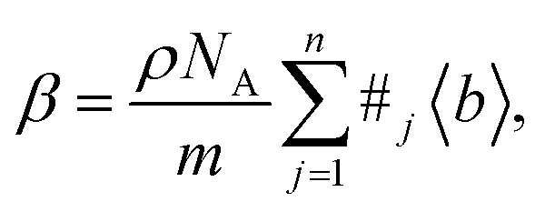
In principle, b is a complex number, but its imaginary part is negligible for most nuclei interacting with thermal neutrons which allows b to be treated as a real quantity. Both the independence from λ and the real treatment of b depend on the low absorption of thermal neutrons by the nucleus. For nuclei that strongly absorb thermal neutrons the appropriate corrections to the collected data must be applied for its accurate analysis. The quantity b depends on the makeup of the nucleus and the orientation of its spin relative to that of the neutron. The quantum mechanical nature of these characteristics means that b is isotope specific and does not vary in a simple monotonic way (Fig. 6), which is the reason why neutrons are well-suited to study light or neighbouring elements containing samples. Moreover, same-element atoms with isotopic distributions and non-zero spins will have an average b and a standard deviation, Δb, which produce coherent and incoherent scattering, respectively. In most neutron scattering techniques, on only the former is of interest, and the later is minimised as much as possible as it produces a background that reduces the signal to noise ratio. A typical example of this practice is substituting the sample's of hydrogen for deuterium whose incoherent scattering cross section is 10 times lower than that of hydrogen. A notable exception is in quasi-elastic neutron scattering, where the incoherent component use used to gather information on lattice dynamics.
 | ||
| Fig. 6 Neutron scattering lengths of different isotopes (those relevant to battery materials are labelled). The magnitude of b is indicative of the isotope's scattering strength and its sign indicates a 180° phase difference relative to values with the opposite sign. | ||
The low magnitude of b, in the order of tens of fm, is responsible for the weakly interacting nature of the neutron. As mentioned before, this allows it to be highly penetrating compared to other probes, such as X-rays. The downside to this is that the counting rates of scattered neutrons are substantially lower than those of their electron-cloud interacting counterparts. Coupled with the much lower fluxes that can be typically achieved compared to X-ray synchrotron sources, neutron scattering measurements are limited in the rate at which data can be collected and require larger sample and beam sizes as well as highly concentrated samples. It is important to note that, although the previous discussion has been mainly based on the neutron's nuclear interaction, which is partly responsible for the non-damaging property of the probe, it can also interact with any magnetic moment within the sample, such as those created by unpaired electrons, via its spin. This allows it to be used to study magnetism-related phenomena, however, a discussion of such capability is beyond the scope of this review.
At the time of this writing, there are two main types of neutrons sources for neutron scattering experiments; continuous sources, and pulsed sources. Most continuous sources make use of a nuclear reactor where neutrons are produced by fission of fissile elements such as 235U. Reactor sources can yield high fluxes of up to 1015 s−1 cm−2 of a wide range of neutron wavelengths. However, since it is not possible to know the wavelength of the neutrons in a continuous source before they hit the sample without chopping the beam, it needs to be monochromated to become useful for neutron scattering experiments. This causes most of the flux to be lost. Moreover, the moderators determine the highest energetic (lowest wavelength) neutrons that can be produced in a reactor source which can be a limitation for high-energy neutrons experiments.
Spallation neutron sources have been more recently developed and are based on particle accelerator technology. In this type of source, neutrons are generated by colliding an accelerated beam of protons with a heavy element target such as tungsten, lead, or mercury. Generally, the accelerated protons are fired at the target in periodical bursts or pulses with typical repetition rates between 10 and 60 Hz. In a pulsed source, it possible to know the common starting point of all the neutrons and subsequently determine their wavelengths through the time of flight technique. This removes the need to monochromate the neutron beam which means that most of the beam is used, and thus the final flux available from a pulsed spallation source is comparable to that of a continuous reactor source despite the usually lower raw flux produced by the former. Although not common, spallation sources can be made continuous and reactor sources can be made pulsed. Two examples of this are the Swiss Spallation Neutron Source, SINQ, in Switzerland, and the IBR-2 reactor in Russia. It is important to note that, depending on the type of source, the technical requirements of an experiment, data processing challenges, and analysis limitations can be different. Users are, therefore, advised to consult a specialist when designing an experiment.
For an in-depth discussion of scattering theory and neutron sources the reader is directed elsewhere.20–23 Meanwhile, the final remark of this brief overview is that it is in how the differential cross-section is measured, expressed and analysed, that each scattering technique differs. This variety of ways to treat the differential-cross section enables the study of many structural and dynamic characteristics at a wide range of length and time scales in matter. The remaining of this section will focus on discussing the utility of each relevant neutron scattering technique for the study of battery materials. A brief explanation of the working principles of each technique in the context of battery research will also be provided.
3.1 Neutron diffraction
Structure determination via diffraction is the pillar of chemistry, biology, solid-state physics, mineralogy, and materials science. The theory of diffraction involves the analysis of the differential cross-section described for crystalline materials with a highly ordered and repetitive structure that can be fully constructed by applying translational symmetry to a motif.21,24 However, a more common way of describing the diffraction phenomenon is through Bragg's law.25 In general, a crystalline material can act as a diffraction grating to incident waves such as a neutron beam, resulting in discrete reflections across a given Q range. The position of these reflections contains information on the size and shape of the unit cell, while the intensity of the diffraction profile contains information on the atomic composition. Analysis of this data can provide a complete understanding of a crystalline structure. Experimentally, measurements can be performed on thin film, single crystal or powder samples, the latter is the most relevant for battery studies.As mentioned, the intensity profile of a powder diffraction pattern contains information of the contents of the unit cell, and the best way to extract this information is to perform Rietveld analysis.26 A Rietveld refinement involves a least squares minimisation process of the data against the calculated pattern from a complete structural model. This can allow the refinement of lattice parameters, atomic positions, occupancies, atomic displacement parameters (ADPs). From this one can easily extract information such as bond distances from the refined model.
This technique is therefore suited to understanding the crystalline structure of new solid-state materials (cathodes, anodes, electrolytes). It is particularly well-suited to locating Li/Na in electrode materials,27,28 Li/Na occupancy,29 distribution of cations in TM cathodes,30,31 magnetic structure,32 M−O bond lengths and cation oxidation state,33,34 and understanding structural changes during cycling.35–37
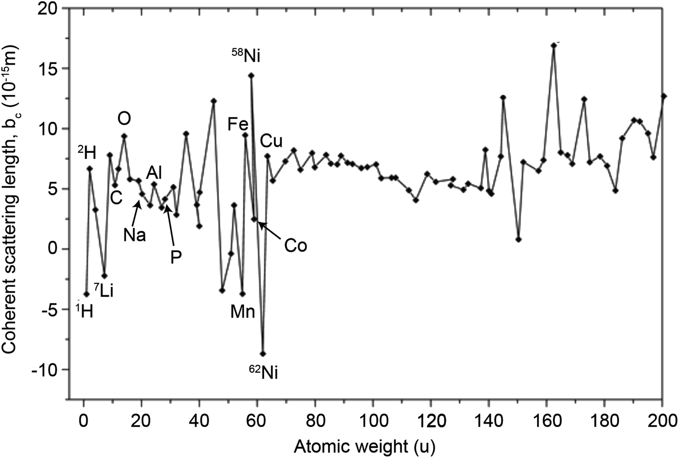
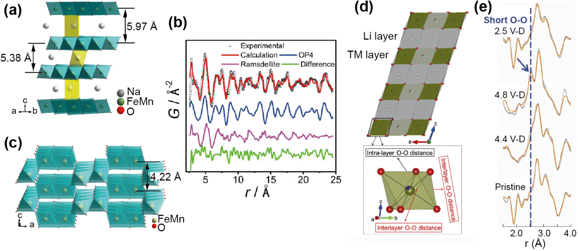
Medarde et al.39 explored the structure and Na+ diffusion pathways of the layered cathode material Na0.7CoO2 using the high resolution diffractometer HRPT at SINQ. They identified two phase transitions on heating that are a result of very small structural distortions and so required high resolution to resolve the small peak splitting at high angle, seen in Fig. 7a. Structural details were extracted using Rietveld refinement, such as the distance between the two Na sites, their occupancies, and their displacement parameters. After the first transition to the intermediate phase, they observed that one of the Na1–Na2 distances increases dramatically, the occupancies show a transfer from one site to the other, and the overall Na occupancy decreases slightly. These all indicate Na mobility, and they use Fourier difference mapping to show 1D and 2D diffusion pathways.
 | ||
| Fig. 7 (a) A contour intensity plot showing a high angle region of the NPD pattern of Na0.7CoO2, showing the phase transitions. (b) Fourier difference maps of the z = 0.25 Na planes at T = 50, 350, 450 K, showing the residual density at the Na sites for the different phase regions that indicate diffusion pathways evolve from 1D to 2D. Reprinted figures with permission, Copyright 2013 by the American Physical Society. (c) Structure of P2-Na0.6[Cr0.6Ti0.4]O2, showing split Na sites in grey.40 Copyright 2015, CC BY 4.0. | ||
Fourier difference maps are a powerful way to visualise diffusion, as intensity indicates missing nuclear density from the model in real space. The map (Fig. 7b) in the intermediate regime showed intensity between two Na sites, revealing a quasi-1D diffusion path. It also indicated an interstitial Na site, that is consistent with the structural changes in this phase. The higher temperature maps showed additional intensity between the other Na sites, revealing the 2D diffusion pathway now accessible. This study shows how high resolution powder diffraction can reveal subtle changes in structure and infer Na diffusion pathways in a Na-ion cathode material.
Neutron diffraction also excels at understanding cation distribution in TM cathode materials.30,31 The high resolution neutron powder diffraction experiment on Na cathode material P2-Na0.6[Cr0.6Ti0.4]O2 is a good example of this. The study focused on characterising the Na/vacancy and cation ordering, both known to impact electrochemical performance.40 In this case NPD is an especially powerful tool as it is sensitive to Cr/Ti order (bCr = 3.635 fm, bTi = −3.370 fm), but in addition to this the Cr/Ti sublattice has a relatively small overall scattering length (b = 0.833 fm) which means the Na (b = 2.18 fm) has a relatively large contribution to the pattern. A diffraction experiment on the high resolution diffractometer Echidna at ANSTO revealed that the cations are randomly disordered, and the Na are split into two slightly off-centre sites (Fig. 7c). To investigate structural changes on cycling, samples with Na = 0.33, 0.5, 0.6, 1 were prepared, and an increase in Na mobility and disorder as Na content decreases was observed. This was expected as a result of the interlayer distance and Na vacancy content increasing. This example shows how the difference in neutron scattering lengths can result in desirable contrast, to reveal structural changes that occur with chemical substitution and the impact on Na diffusion.
Prussian blue analogues (PBAs) are of interest as Na-ion cathode materials, and the presence of water is known to impact the structure and properties of PBAs.41,42 Characterisation using X-rays is particularly challenging, as they contain elements with a similar number of electrons; C and N, H2O and Na, as well as the transition metals. Therefore, neutrons are a particularly useful tool in characterising the structure including the location of water as exemplified in a recent study.42 Neutron diffraction was used to investigate the impact of water on the structure of Prussian white, a Na rich PBA. Fourier difference maps were used to locate the H2O oxygen within the framework, understand how this influences the overall structure, and therefore improve synthetic control over the structure and electrochemical properties of this family of cathode materials. Another example of where the contrast provided by neutron diffraction has been shown to be particularly useful is for structure determination in the Na NASICON cathode family, either for distinguishing between Mn and Cr in Na4MnCr(PO4)3,43 or O and F in the fluoride-doped Na3V2(PO4)3.44
There are many aspects of battery characterisation that cannot be understood with ex situ studies alone. Operando diffraction studies can reveal the evolution of the electrode structure,45,46 formation of intermediate/metastable phases,47 dynamics of intercalation/deintercalation,37,48 and component degradation on electrochemical cycling.49,50 Neutrons are the ideal probe to study an operating battery system, as they interact relatively weakly with matter and so can easily penetrate complex sample environments, and are sensitive to lighter elements such as Li. There are many examples of operando experiments, using either commercial cells or custom cells optimised for data quality, that provide key insights into the electrochemical performance of battery systems.45–49
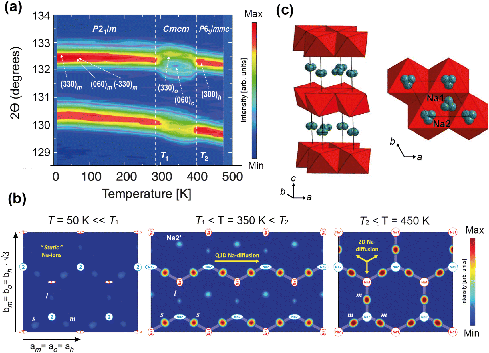
A good illustration of the power of in situ neutron studies is provided by the work of Sharma et al.35 on a commercial prismatic cell. The cell containing LiFePO4/graphite was cycled at various currents and temperatures, and the structural evolution of the LiFePO4 cathode observed. The LFP system has been the subject of multiple studies that show inconsistencies in the phase evolution of LiFePO4, indicating that the structural changes on charge/discharge depend on the experimental conditions. This operando experiment on the commercial cell allowed the authors to shed light on the dependence of the structural response on the operating temperature and current.
The authors were able to extract information using Rietveld refinement, where the refinement, data, and extracted parameters are shown in Fig. 8a–c, respectively. They found that a sharp rise in temperature is detrimental to the battery and causes irreversible changes, and that a lag in the phase evolution between LiFePO4 and FePO4 occurs following an increase in current. They also observed that the phase evolution is faster for charge than for the discharge process under the high temperature and current conditions. Observing the structural evolution of the electrodes inside the working commercial cell is vital to understanding the dependence of the cycling processes on temperature and current.
 | ||
| Fig. 8 (a) The Rietveld refinement profile using data of LiFePO4in operando experiment, where data are red crosses and the calculation is shown in black and the difference between the two in purple. Vertical lines are Bragg reflection markers for the various battery phases as identified. (b) A contour plot of in operando NPD data shown in a selected 2θ range (56–79°) composed of 534 NPD patterns that are stacked along the y-axis (time). (c) The evolution of the LiFePO4 (black) and FePO4 (red) relative weight fraction, along with the measured voltage (blue), applied current (purple), and temperature of the battery at the surface closest to (red) and at the other side (green) of the halogen lamps. Reprinted from ref. 35 Copyright © 2017 with permission from Elsevier. | ||
Operando measurements have also been used to understand degradation mechanisms in commercial batteries. Von Lüders et al.51 used in situ NPD to investigate Li plating in 18650 commercial LFP/graphite cells at −2 °C. By tracking the intensity of the LiC6/LiC12 peaks at different rates of charge, as well as on relaxation, they showed that the proportion of stage 1 (LiC6) to stage 2 (LiC12) is current-dependent, and that on relaxation stage 2 converts to stage 1 as the metallic lithium intercalates into the graphite. Although there was not enough metallic plated Li to be detected in the pattern, they used the difference in degree of lithiation (calculated from structure factors) before and after resting to estimate the amount of Li plating. This enabled them to extract a correlation between charging rate and Li plating, where they found that the amount of plating correlates non-linearly with the charging rate. Furthermore, above a threshold current of C/5, lithium plating increased dramatically.
Studies such as this one that can give insight into degradation processes in the commercial cells are integral to improving their performance. However, extracting structural information from commercial batteries using in situ NPD is challenging. Commercial cells contain components such as steel casing that produce very strong Bragg peaks, as well as H-containing components that contribute to the background, and this combined with small electrode quantities results in weak NPD signal from the electrode itself. The development of custom made cells is the best way to achieve in situ NPD data of sufficient quality for Rietveld refinement, whilst maintaining acceptable electrochemical performance.
A custom cell design aims at maximising the coherent scattering from the active material relative to the coherent scattering from other components and the incoherent background signal from the hydrogen-containing components. This is challenging as the electrolyte, separator, and binder often contain hydrogen which has a large contribution to the background due to its large incoherent scattering cross section. Furthermore, neutron measurements require a large amount of sample, much more than what is in a standard coin cell. Unfortunately, the electrochemical performance is best for small electrode quantities. Various designs have been developed to attempt to overcome these challenges, and these are shown in Fig. 9. The main consideration for overall cell geometry is if the cell is for a reactor (monochromatic) facility or for a pulsed (time-of-flight) one. An advantage of a pulsed source is that diffraction experiments are fixed-geometry which allows, for example, use of the coin cell geometry. On the other hand, reactor sources will typically have dynamic experimental set-ups in order to maximise the accessible diffraction angles, and for this a circular based cell geometry is preferred.
 | ||
| Fig. 9 (a) Cylindrical cell developed by Bergstöm et al.52 at Uppsala with gold-plated Pyrex tube. Reproduced with permission of the International Union of Crystallography. (b) Cylindrical cell developed by Vitoux et al. at PSI with double-sided cathode.53 Copyright 2018, CC BY 4.0. (c) Representation of TiZr Swagelok cell developed by Bianchini et al.54 at ILL, with TiZr alloy “null matrix material” as casing and current collectors. (d) Circular cell developed by Godbole et al.55 at PSI, with aluminium outer body and titanium plunger used to create pressure. Reproduced from ref. 55 with permission from the Royal Society of Chemistry. (e) Pouch cell developed by Pang et al.56 at ANSTO with electrodes in a parallel connecting stack. Reproduced with permission of the International Union of Crystallography. (f) Wound electrode cell by Roberts et al.57 Reprinted from ref. 57 copyright © 2012 with permission from Elsevier. (g) Roll Over cell developed by Sharma et al. at ANSTO58 Reprinted from ref. 58 copyright © 2011 with permission from Elsevier. (h) Coin cell developed by Dong et al.59 | ||
One way to satisfy the requirement for a large amount of active material while maintaining the electrochemical requirements is a design that has stacked layers, either rolled or in a pouch cell. Some of these designs also allow a double sided electrode resulting in double the active material. In order to reduce the background, the hydrogen electrolyte can be replaced with a deuterated electrolyte, as deuterium has a much lower incoherent scattering cross section. This is done in a lot of cases but the downsides are the cost, as well as potentially sluggish electrochemistry. In addition to this one may replace the hydrogen containing binder and separator, however a different separator might require more electrolyte so this needs to be taken into consideration. Another factor is the electrode preparation – while using a powder is the most straightforward option, processing the powder to apply a coating to the current collector will give superior electrochemical performance.
The cell developed at ISIS shown in Fig. 9h is a coin cell, a geometry that is common for X-ray experiments that has been scaled up to hold a sufficient amount of electrode material for neutron studies. The body of the cell, cell windows, and the current collectors that hold the electrode material are all made of nickel. The choice of nickel was made based on its simple diffraction pattern and small background contribution. The use of this cell was demonstrated in a recent study on Polaris showing the structural evolution of LiCoO2.59 The electrochemical performance of the assembled cell was tested and found to be similar to that of a standard coin cell. Neutron diffraction patterns were collected ex situ for cells with deuterated and protonated electrolyte. The cell with deuterated electrolyte resulted in a lower background as expected, with the data comparable to the measurement of LiCoO2 in a vanadium can. The in situ experiment with 10 min collection times resulted in good quality data, from which structural evolution could be followed with Rietveld refinement.
Bianchini et al. designed a novel electrochemical Swagelok cell for in situ and operando neutron diffraction, shown in Fig. 9c.54 The cell geometry allows the beam to pass through the active material only, as well as the casing which is a Ti–Zr alloy that is a so called “null matrix material”. As the neutron scattering lengths for Ti and Zr are bTi = −3.37 × 10⁻¹² cm and bZr = 7.16 × 10⁻¹² cm, the overall neutron scattering intensity can be tuned to zero when they are combined in a roughly 1:2 ratio. The electrochemical performance and quality of diffraction data of the cell was tested with the well-known positive electrode material LiFePO4, using deuterated electrolyte to reduce the background. The data was of sufficient quality to extract structural parameters from Rietveld refinement, including Li occupancy, in good agreement with those obtained from measurement of the pure powder. Because of the cell design, the data were fit with a single phase – that of the active material. The operando data showed the complete two-phase reaction between LiFePO4 and FePO4, consistent with the electrochemistry, and reliable structure parameters could be extracted for these measurements.
Whilst in situ/operando studies using neutron powder diffraction has provided many insights into the structural behaviour of battery materials during the charge/discharge processes, the major drawback of the technique is the relatively long counting times (typically several minutes) required to collect data of sufficient statistical quality for full structural characterisation. This normally precludes studies at the fastest charge/discharge rates, but these will become accessible in the future with the construction of new powder diffraction instrumentation at more powerful neutron sources (e.g. the ESS). However stroboscopic measurements are able to overcome this challenge using the current neutron sources, as demonstrated by Sheptakov et al.60 on Li-ion LiNi0.5Mn1.5O4 full cells in the first application of stroboscopic neutron diffraction.
3.2 Neutron total scattering
Diffraction as a technique is incredibly powerful, but it is limited to studying the average structure of crystalline materials. As a result, it is not suitable for characterising disorder in crystalline systems, or the local structure of amorphous systems. In contrast to this, total scattering analysis can be used to study the local structure of materials that need not have long range order. The atomic pair distribution function (PDF) obtained from total scattering data, historically used to study the structure of liquids and glasses, is now a widespread analysis technique used to study the local structure of a range of materials.The PDF, usually used in reference to the radial distribution function G(r), is the weighted probability of finding a pair of atoms separated by a given distance (r). This function, that exists in real-space, is the Fourier transform of the total scattering function, S(Q). The total scattering function is obtained by diffraction measurement that contains not only the Bragg peaks, but the diffuse scattering that is usually treated as background in traditional diffraction.
Diffuse scattering contains information on deviations from the average structure, and so the PDF probes local structure and its analysis is not dependant on long-range order. This analysis is applicable to a range of materials and a range of problems in materials science; disordered components or defects in crystalline materials, materials with limited long range order such as nanoparticles, and materials with no long range order i.e. amorphous materials. The insight into the local structure has been found to be essential in understanding function in complex materials such as oxide ion conductors,61 piezoelectrics,62 and colossal magnetoresistor perovskites.63
The neutron total scattering experiment itself has the same general set-up as a neutron diffraction experiment. However, since both the Bragg and diffuse components are measured, a few additional considerations exist with respect to the diffraction measurement. Firstly, the scattering due to the anything other than the sample, for example the sample holder, must be identified and ideally removed. This usually requires extra measurements of the empty instrument and sample holder. The other requirement is of a large Q-range, as this translates to real-space resolution in the PDF. The development of high intensity synchrotron X-ray sources and neutron spallation sources has increased the accessible Q-range, and therefore the accessibility of total scattering measurements in general.
Calculated diffraction and PDF patterns of the cathode LiCoO2 are shown in Fig. 10a and b, and Fig. 10e shows the low-r region of the PDF with dashed lines corresponding to the closest interatomic distances represented in Fig. 10d. The structural information that the PDF can provide is the bond lengths from the peak positions, variation in bond lengths from the peak widths, abundance of atomic pairs from the peak area, and finally the particle size or coherence length from how far in r the peaks reach. Depending on the system, some of this information can be obtained using simple peak fitting, but more complex analysis is usually required. The most common analysis is small-box modelling in which a model, usually the average structure, is refined to fit the data in a process similar to a Rietveld refinement. More in-depth modelling involves making larger models to compare to the data, and can be as complex as reverse Monte Carlo (RMC) usually referred to as big-box modelling.64 RMC involves generating a supercell, or large atomistic configuration, and allowing atoms to make moves that are judged by how well the calculated model fits the experimental data. The moves are accepted or rejected according to a Metropolis criteria, and after many iterations should produce a configuration that minimises the difference between the calculated and experimental PDF. Although a powerful technique, the results must be taken with consideration of the limitations; that RMC will give the most disordered configuration, and that a single result is one of many configurations that may give the same PDF fit.
 | ||
| Fig. 10 Calculated neutron scattering (a) and PDF (b) of LiCoO2, the layered structure is shown in (c) and the CoO6 sub-unit is shown in (d), with interatomic distances represented by dashed lines, and the corresponding positions in the PDF shown in the low-r region (e). The Co, O, and Li are represented by blue, red, and yellow spheres, respectively. | ||
Rechargeable battery systems are comprised of many complex materials that present characterisation challenges. While a lot of these materials are crystalline, there are many examples of electrodes with amorphous structures, and electrodes are often used in nanoparticle form for larger surface area. Diffraction is not able to extract structural information from either amorphous or nano systems, but PDF analysis can. Overall, the main applications of neutron total scattering experiments in battery characterisation is determining short and medium range order in electrodes and solid state electrolytes,67–69 understanding local TM arrangement,70,71 identifying and characterising amorphous components of electrodes including hard carbon, Si, and products of cycling,65,72–74 and observing local structural distortions in electrodes as a result of cycling, including anion redox.66,75,76 The current limitation of NPDF is that relatively long collection times and the complication of additional components in extracting the PDF of the active material makes operando experiments extremely challenging.
For example, PDF analysis was used to show that the observed capacity loss in the P2 Na-ion cathode material Na0.67Fe0.5Mn0.5O2 is a result of an irreversible transformation to a disordered phase.65 In this ex situ experiment a chemically desodiated sample was measured, in order to study as pure a sample as possible (free of carbon and binder). The total scattering of Na0.23Fe0.49Mn0.5O2 was measured using the NOMAD diffractometer at the SNS, and the resultant PDF analysed by a small-box approach. The phase transition on cycling, as observed by operando XRD, is from the P2 to an OP4 structure. Using the OP4 as a model (Fig. 11a) was insufficient to fit the PDF data at low r, leading to the possibility of the presence of a disordered phase not detected by XRD (due to lack of long range order). Indeed, the data were successfully fit (Fig. 11b) with the addition of a MnO2-type Ramsdellite phase with a short coherence length, represented in Fig. 11c. Using PDF analysis the structural details of this phase were determined, and it was found to be a Na-depleted phase. The analysis also revealed the relationship of this phase to the parent P2 phase and its formation on cycling, that it is irreversible, and that this explains the poor cycling performance of the material. PDF analysis of total scattering data was essential in discovering this disordered phase and the origin of performance reduction.
 | ||
| Fig. 11 (a) Structure of the OP4 phase. (b) Refined NPDF pattern of the desodiated sample, showing contributions from the OP4 phase and the ramsdellite phase. (c) Schematic illustration of the ramsdellite structure. Reprinted with permission from ref. 65 Copyright 2020 American Chemical Society. (d) Structure of Li1.2Ni0.13Mn0.54Co0.13O22 and TMO6 octahedra showing interlayer and intralayer O–O distance. (e) Comparison of the ex situ NPDF results of LMR-NMC collected at different charge–discharged states. Reprinted from ref. 66 Copyright (2020), with permission from Elsevier. | ||
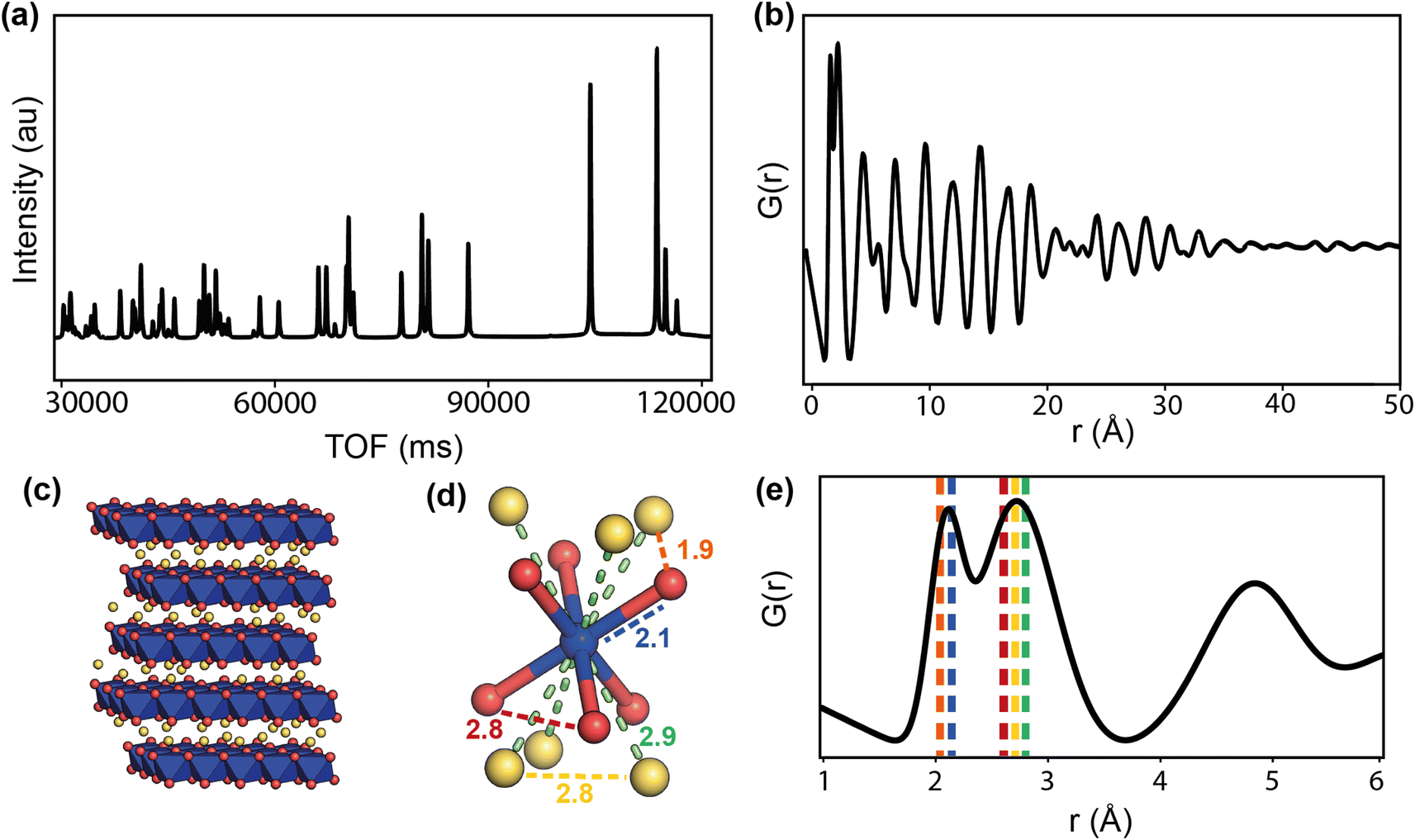
Anion redox is an important process, with the potential to add capacity to the system, but can also cause irreversible damage if the redox results in O2 recombination. Understanding this process in electrodes is important, but can be difficult to observe as it usually occurs locally. Zhao et al.66 used PDF analysis of total scattering data, collected on the POWGEN instrument at the SNS, to observe the structural changes in a Li-ion cathode Li1.2Ni0.13Mn0.54Co0.13O2 due to oxygen redox. Using an ex situ experiment on samples of different charged–discharged states, they observed the change in local structure upon cycling (Fig. 11e). The PDF showed two O–O peaks due to the distorted TMO6 octahedra (Fig. 11d), and they observed that the amount of interlayer short O–O distances increased as a structural response to oxygen redox. This increase disappeared on discharge, demonstrating that the structural distortion is reversible. They used theoretical calculations to support the finding that this local lattice distortion accommodates the oxygen redox whilst maintaining the average structure of the material, and that this response is sensitive to the TM–O bond character.
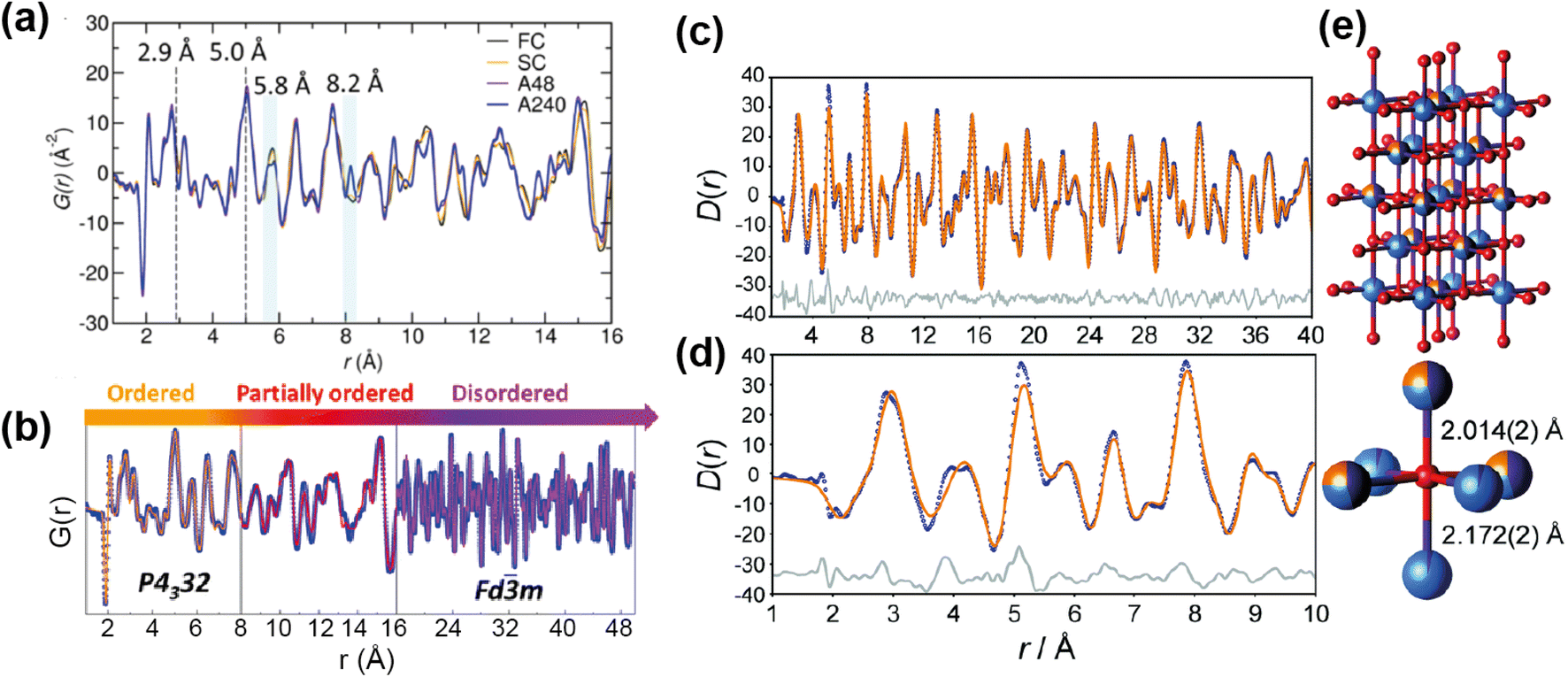
One area in which neutron total scattering excels is in determining local TM cation arrangement. There are two families of TM oxides that have received a lot of attention as Li-ion cathodes and contain cation disorder; spinel-type LiMnNiO4, and Li-rich rocksalt-type structures such as Li1.25Nb0.25M0.05O2 and Li1.9Mn0.95O2.05F0.95. The spinel LiMnNiO4 exists as both an ordered and disordered polymorph, with the former accessed by adding a post-annealing step to the synthesis. While both polymorphs are attractive materials, the disordered structure with Ni/Mn randomly disordered is generally considered to have the better electrochemical performance. This was assumed to be as a result of the locally disordered cation arrangement, albeit the exact mechanism unknown. A recent study71 used PDF to explore the short, medium, and long range order of the “ordered” and “disordered” polymorphs, as well as fast and slow cooled samples of each of these. The large difference in neutron scattering lengths between Ni (10.3 fm) and Mn (−3.73 fm) make neutron total scattering an optimal technique to study the relationship between synthesis, short range structure, and electrochemical performance in this system.
The neutron PDFs of the four samples are shown in Fig. 12a, with the first result being that the short range order (below 5 Å) does not vary i.e. all have Ni/Mn order below this length scale. Above this range, both of the “disordered” samples, fast and slow cooled, appeared to have Ni/Mn disorder, while both “ordered” samples appeared to have Ni/Mn order, as expected. Small-box modelling was implemented to quantify the order/disorder over the different length scales (Fig. 12b).
 | ||
| Fig. 12 (a) PDFs of ordered and disordered polymorphs of LiMnNiO4. (b) Fitted PDF of the disordered sample with sections showing the regions of the PDF that differentiate the samples. Reprinted with permission from ref. 71. Copyright 2016 American Chemical Society. (c and d) Neutron PDF data for an ordered slow-cooled sample of Li1.25Nb0.25Mn0.5O2 that has been fitted using a structural model based on the unit cell of γ-LiFeO2. (e) The O coordination environment is shown (bottom-right) along with the two axial bond lengths.77 Reproduced from ref. 77 with permission from the Royal Society of Chemistry. | ||
Interestingly, while for the ordered samples there was no difference in the PDF up to 50 Å and the same low level of Ni/Mn mixing was extracted from refinement, the Rietveld refinement of these materials gave a higher Mn/Ni mixing (14%) for the sample with shorter post-annealing. Additionally, this sample had better rate capability than its longer post-annealed counterpart. The results here indicated that the better performance can be attributed to higher length scale features, such as ordering domain size or domain boundary defects, instead of differences in local Mn/Ni mixing. This result showed that only post-annealing significantly impacts the long-range order of the sample, and that local Mn/Ni order is achieved for the samples with and without post-annealing.
The other family of materials mentioned above, Li-rich cation disordered rocksalt structures, also pose characterisation challenges with inherent disorder that gives rise to desirable diffusion properties. Jones et al.77 used PDF analysis to study the local structure of Li1.25Nb0.25Mn0.5O2, comparing samples with fast and slow cooling rates. The slow-cooled sample displayed additional reflections in the PXRD indicating additional order, indexed as tetragonal, while the fast-cooled sample was more disordered and cubic. PDF analysis revealed additional information about cation order for the tetragonal structure, this indicated that the TM sites are split (Fig. 12e). The model was refined against the PDF data, and this revealed that the cation distribution contains additional local order, and these occupancies were extracted from the PDF refinement (Fig. 12c and d). These examples demonstrate that total scattering can reveal subtle structural phenomena that can have important implications for the electrochemical performance.
3.3 Small angle neutron scattering
Whilst high resolution information about the atomic structure of materials can be obtained by analysing the scattering cross-section at high Q, larger scale (nm–μm) structures, morphology, and phenomena can be investigated by analysing the scattering cross-section at low Q. By combining Bragg's law and eqn (2), the relationship between Q and the length-scale probed can be easily obtained as:
Thus, larger length-scales can be investigated by increasing the wavelength of the scattering probe and measuring the scattering cross-section at smaller angles. Since the experimental setup (Fig. 13) and the analysis theory are heavily based on the later, this technique is called small angle scattering, or more specifically when neutrons are the scattering probe, small angle neutron scattering (SANS). The small angle approximation, which states that when 2θ ≈ 0, sin2θ = tan2θ = θ, makes the analytical modelling of the data possible in the same way as the distance between two scatterers can be determined by multiplying the wavelength of the scattering probe by the length between the scatterer and the detector and dividing them by the distance between fringes in a diffraction grating (Fig. 14).
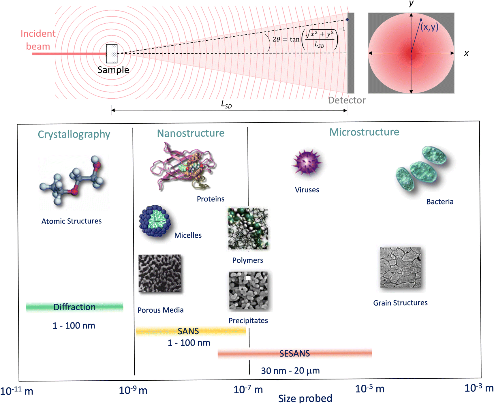 | ||
| Fig. 13 (Top) Geometry for a small angle scattering experiment. The size, d = λ/(4πsin(θ)), of the objects that can be probed by the technique depends on the wavelength of the incident beam, λ, and the scattering angle, 2θ, at any given (x, y) within the scattering signal. From the expression shown for 2θ it can be seen that the small scattering angles can be achieved by increasing the sample to detector distance, LSD. (Bottom) Scale range accessible by different scattering techniques. Adapted from Pynn 1990.78 | ||
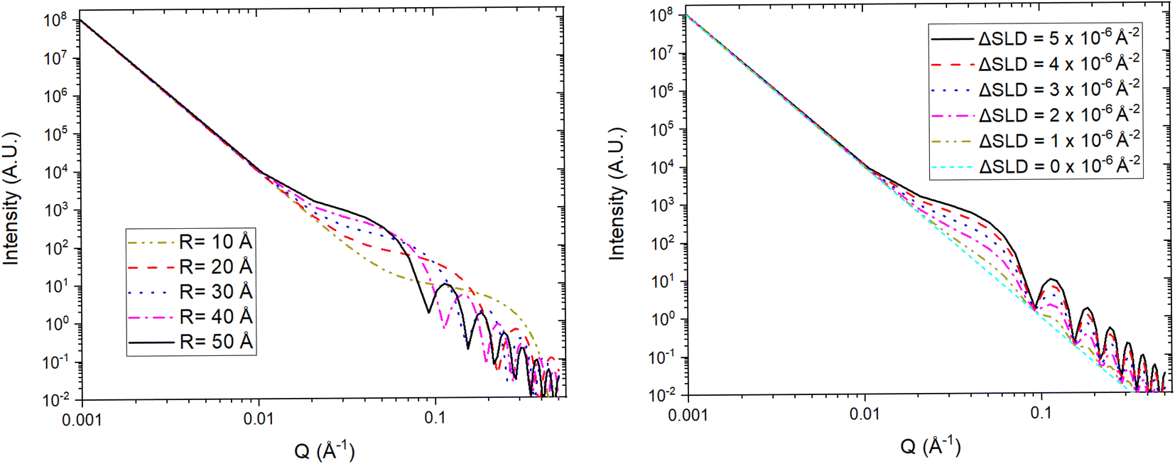 | ||
| Fig. 14 Simulated SANS profiles from a type of simple porous electrode with idealised spherically shaped nanopores. (Left) The position of the fringes, produced by the coherent scattering from the nanopores, in Q depends on the radius (R) of the electrode's pores. (Right) The intensity of the fringes is proportional to the scattering contrast (ΔSLD) between the pores and the electrode network. A three phase system (e.g. liquid electrolyte, electrode network, and SEI in pores) can be reduced to a two phase system by matching the SLDs of two phases (e.g. SLDelectrolyte = SLDelectrode network). | ||
For a simple sample, i.e. a solution consisting of monodisperse, isolated, and isotropically oriented objects of interest in a sea of solvent, the low Q part of a SANS spectrum can be analysed to obtain information about the size and composition of the object of interest while the high Q part can be analysed to obtain information about its shape. This is done through the Guinier approximation, which relates the measured SANS intensity at low Q to the object's classical analog radius of gyration, and the Porod's law, which relates the measured SANS intensity at high Q to the object's surface area.21 More complex samples, such as those that have constituents that are polydisperse, anisotropically oriented, and/or interacting with each other, require the building or use of a customised mathematical model that describes the differential-cross section from such system as accurately as possible. This model is then fitted to the SANS data in an iterative process that varies the sample parameters in the model until a good agreement between the measured data and the model is achieved. Regardless of the complexity of the sample, it is highly desirable to know as many of the sample's characteristics as possible previous to the SANS experiment to reduce the number of unknowns during the data analysis and improve its simplicity and reliability. SANS benefits from the advantages of any neutron technique such as light element detection and contrast matching making it ideal for ion-battery related research. The latter is a particularly useful feature for SANS as the sample can be reduced to a two-phase system, from the technique's perspective, to which small angle scattering theory can be straightforwardly applied. A typical example of this practice in battery research is deuterating a liquid organic electrolyte to match its SLD to that of a porous electrode. The electrolyte filled pores would then become indistinguishable from the electrode network in the SANS signal allowing the dynamic content of the pores, e.g. formation of new chemical species, to appear as a secondary distinct phase in the signal. Since SANS probes at the nano-micro scale, this technique is ideal to study the size, shape, and distribution of particles and pores in electrode and solid electrolyte materials. Perhaps more crucially, the composition of the pore contents can also be investigated making it possible to study phenomena such as ion intercalation and SEI formation.
Variable-wavelength neutrons can be produced in both reactor and spallation sources, however, due its pulsed nature, and consequent time of flight data format collection, the latter is generally better suited for the use of neutrons with different wavelengths. As shown in Fig. 13, small angle data detection can be achieved by using long flight paths between the sample and the detector, which is often equipped with the ability to move closer or farther away from the sample. The combination of variable wavelengths and sample-detector flight distances allow for the collection of SANS data within a wide range of Q. Further lower Q values can be accessed by sister techniques such as Ultra SANS (USANS) and Spin-Echo SANS (SESANS), however their utility for investigating battery materials has yet to be demonstrated in literature.
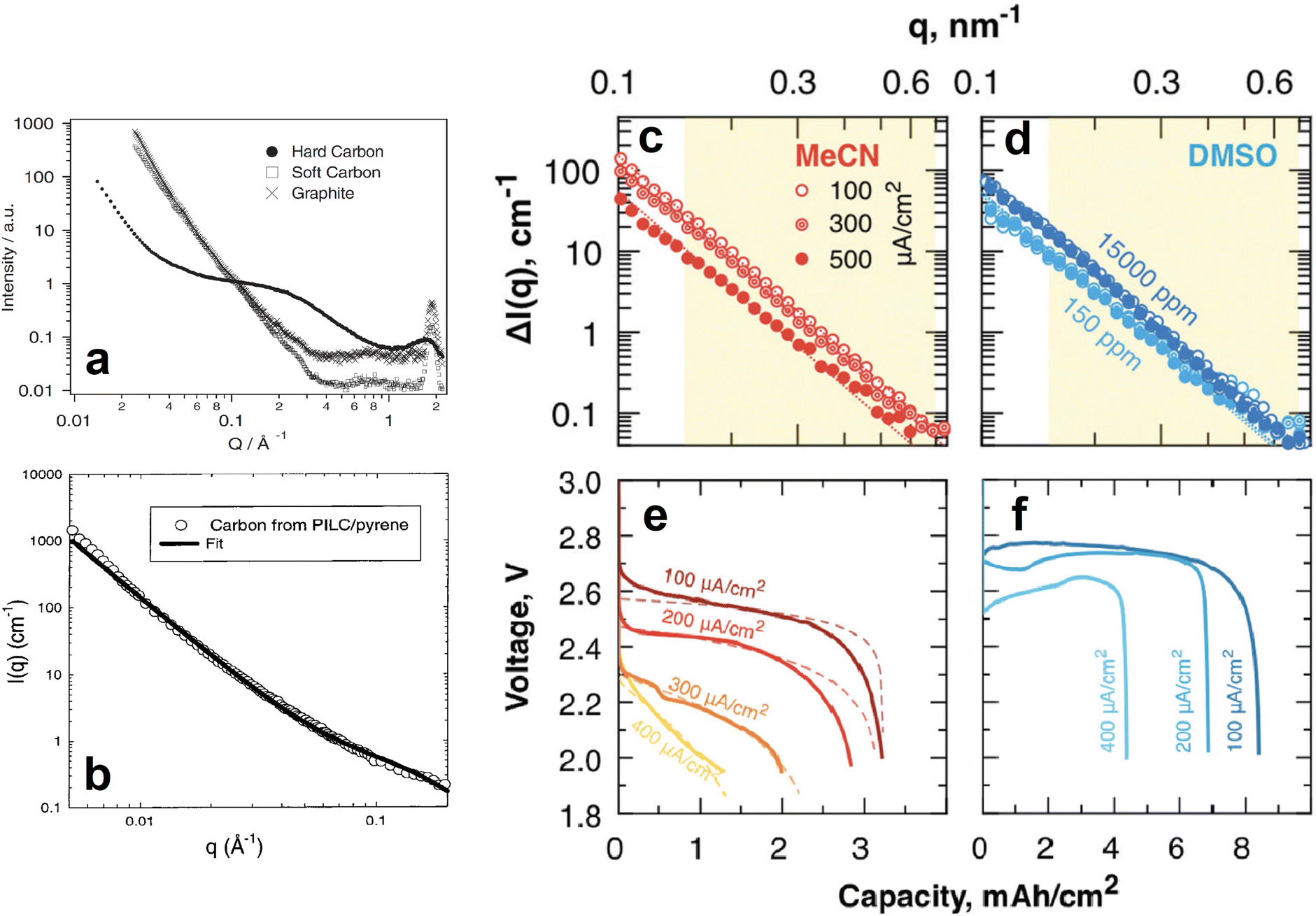 | ||
| Fig. 15 (a) SANS 1D profiles of different carbon based anodes. Reproduced with permission from ref. 79. Copyright © 2002, Springer Nature. (b) SANS data and corresponding fit of a pyrolyzed pillared clay synthesised from a pyrene precursor. Reproduced with permission from ref. 80. Copyright © 1999, American Chemical Society. (c–f) SANS 1D profiles of MeCN (c) and DMSO (d) soaked, carbon paper electrodes fully discharged at different current densities (e and f for MeCN and DMSO, respectively). Reproduced with permission from ref. 81. Copyright © 2019, Royal Society of Chemistry. | ||
Similar SANS experiments have also been conducted on cathode materials to understand the role of their nanostructures in the performance and lifetime of batteries. For example, most promising Li/Na–air batteries use mesoporous carbon as the cathode, and investigating the phenomena occurring within the pores is crucial to the development of this particular battery technology. SANS was used by Zakharchenko et al. to investigate the filling of these pores with Li2O2 at various discharge current densities when the carbon is in a poor, acetonitrile (MeCN), and in a good, dimethylsulfoxide (DMSO), solvating medium (Fig. 15c–f).81 Researchers partially deuterated both solvation media to contrast match their SLDs to that of the carbon black cathode so that the Li2O2 entering the pores upon discharge could be tracked. The SANS intensities of the fully discharged MeCN soaked cathodes decreased as the discharge current density increased (Fig. 15c). The calculated pore fraction of the cathode at the lowest discharge current density was ≈85% and decreased to ≈25% at the highest discharge current density. In contrast, the pore fraction of the fully discharged DMSO soaked cathodes was the same throughout the different discharge current densities. This was evidenced by their very similar SANS intensities (Fig. 15d). SANS can also be a powerful tool in determining the structure and orientation of cathode nanoparticles. He et al. used SANS to determine the particle size, 250 nm, of a porous Li1.2Mn0.56Ni0.16Co0.08O2 cathode material and the surface layer thickness, 0.95 nm, of its carbonaceous modified surface.88 These experiments helped to conclude that the cathode's specific structure and composition resulted in high Li+ ion conductivity, good structural stability during intercalation, and reduced volume change, all of which are responsible for the materials high rate and long-term cycling performance. In a similar experiment Chung et al. determined the macroscopic morphology of LiFePO4 crystals whose SANS data was fitted very well by a model describing polydisperse spheres surrounded by a 2 nm shell.89
SANS main historical utility to the battery research community derives from its ability to provide information about the dynamic content of pores in the anode. In addition to its contribution to the isolated analysis of the electrodes, such ability makes it possible to track the formation and evolution of the SEI as the battery is cycled. A clear demonstration of this was done by Jafta et al. who investigated the impact of concentration of a LiN(SO2CF3)2/propylene carbonate (LiTFSI/PC) electrolyte on the microstructural dynamic chemistry of a Li/ordered mesoporous hard carbon electrode based battery.86 This was done by obtaining multiple SANS profiles at different stages of discharge of two cells, each with a differently concentrated electrolyte. All SANS data exhibited a peak in the mid q range caused by the mesopore ordering in the hard carbon. Using an appropriate model to fit the data, the peaks position and intensity in all the profiles were calculated and related to the intra-pore spacing in the electrode and the contents of the pore, respectively. It was found that during the OCV – 1.1 V stage, Li(PC)4 is adsorbed onto both the meso- and micropores of the hard carbon in the cell with the low concentration (1 M) electrolyte, however, Li(PC)-TFSI is adsorbed only onto the mesopores of the sample with the high concentration (4 M) electrolyte due to its high viscosity. The change in contrast variation during this discharge stage indicated that this is when pores are filled, the Li(PC)4 is adsorbed, and the SEI starts forming on the hard carbon surface. In combination with XPS measurments it was also found that LiTFSI gets reduced at a higher voltage in the cell with the 1 M electrolyte and that, during the 1.1–0.9 V plateu/intercalation stage, its SEI has a higher content of carbonaceous compounds (e.g. C–O, C–F) than the SEI of the cell with the 4 M electrolyte which has a higher content of Li salts (LiOH, Li2O, LiF). At the low 0.3–0.05 V region it was also found that the SEI was thinner in the cell with the 1 M electrolyte.
A similar operando SANS experiment was conducted by Bridges et al. in which they used LiPF6-EC/DMC electrolytes with different levels of deuteration in hard carbon based cells.87 The change in the mesopore SANS peak intensity as a function of voltage trend was different during the SEI formation stage (75–372 mA h g−1) but similar during the lithium intercalation stage (372–1500 mA h g−1) in the different cells, each having an electrolyte with a different level of deuteration (Fig. 16e–g). Since the intensity of the peak is proportional to the difference between the SLDs of the carbon matrix and the pore content, the researchers compared the SLD of different compounds to that of the carbon matrix and determined which compounds in each SEI are consistent with their corresponding peak intensity change trends. It was found that the changes in contrast are consistent with the initial formation of carbonaceous compounds (Li2CO3 and/or (CH2OCO2Li)2) during the SEI formation stage followed by the increasing concentration of Li salts (Li2O, LiOH, or LiF) during the lithium intercalation stage. The utility of contrast matching in SANS experiments has also been demonstrated by Risse et al., who used a deuterated electrolyte in lithium–sulfur batteries to observe the time-dependent initial wetting of microporous carbon and to determine that sulfur and Li2S do not precipitate in the micropores.90 Since the SLD of the deuterated electrolyte used is very close to the SLD of carbon, it was possible to treat these two components as a single phase allowing the precipitates to be treated as the second phase for the SANS analysis. This also allowed them to suggest that the smallest particles of Li2S dissolve first than the larger ones throughout the cycling process.
 | ||
| Fig. 16 SANS intensity (cm−1) as a function of the scattering vector q, 1st discharge time and voltage for (a) the 1 M LiTFSI/PC electrolyte system and (b) the 4 M LiTFSI/PC electrolyte system. Electrochemical and operando, and SANS analysus results for the 1 M (c) and (d) the 4 M electrolyte systems – (Top) electrochemical cycling profile; (middle): integrated Gaussian peak intensity for pore ordering and micropore (high q) scattering intensity (MPSI); (bottom) pore–pore spacing determined by the Gaussian peak position. Reproduced with permission from ref. 86. Copyright © 2019, Royal Society of Chemistry. (e and f) Results of fits to in situ SANS data from the Gaussian peak corresponding to the pores in hard carbon with a LiPF6 in EC:DMC electrolyte. The peak intensity versus nominal capacity is shown in (e), and the pore–pore spacing versus nominal capacity is shown in (f). The discharge process is given on the left and charge process on the right, while background colors indicate stages (I) (purple; initial discharge; 2.5–1.3 V), (II) (blue; SEI formation; 1.3–0.7 V), (III) (green; lithium intercalation; 0.7 V–5 mV), and (IV) (yellow; charging; 5 mV–3 V) of the initial charge/discharge cycle. (g) Plots comparing the calculated scattering length densities (SLDs) of the electrolytes, carbon framework, and potential components of the solid-electrolyte interphase (SEI) layer as a function of deuteration level. The deuteration level of the electrolytes varies from 0% to 100%, and the SLDs of the SEI layer have been adjusted accordingly for each case. The yellow band indicates the region over which a component in the SEI will result in a decrease in contrast between the framework and pore relative to a fresh cell, and these components have been highlighted in green for each deuteration level. Only the Li2O and LiOH components will cause an increase in contrast for all deuteration levels. Reproduced with permission from ref. 87. Copyright © 2012, American Chemical Society. | ||
3.4 Neutron reflectometry
The one dimensional change in composition of an object with a thin layered architecture can be investigated by analysing the object's specular reflection of an incident beam of waves, including neutrons. This change in composition is tracked in the direction normal to the surface on which the beam is incident and the sample of interest must have compositional homogeneity along the parallel axes of such plane (Fig. 17). One of the advantages of this single-dimension reduction of the problem is that it is possible to study multiple interfaces as opposed to, for example, small angle scattering in which the investigation is often limited to a single two phase interface.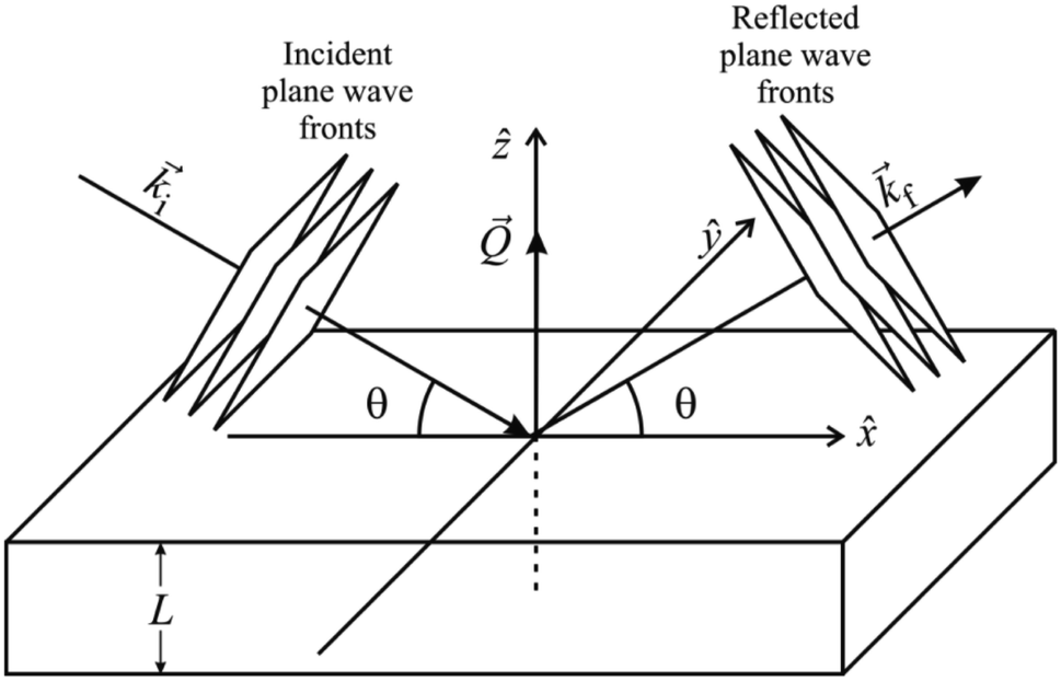 | ||
| Fig. 17 Simplified geometrical breakdown of the reflectometry phenomenon. | ||
To obtain the neutron reflectivity (NR) profile of a sample as a function of Q, a beam of neutrons of variable or fixed wavelengths is directed towards the sample at one or several incident angles. The reflectivity is then collected as a function of θ and/or λ depending on the neutron source and instrument configuration. Whilst off-specular reflectivity can be collected at angles different to the incident one to study lateral heterogeneities in the sample, it is the specular reflectivity that yields the information of the layered structure of the sample in the vertical direction. The differential cross-section of a laterally homogeneous sample with a varying composition in the direction of the vertical axis is related to the specular reflectivity as:
 | (4) |
While eqn (4) describes the reflectivity with sufficient accuracy at high Q, it does not hold at low Q near and below the critical angle, θc, at which total reflection occurs (R = 1). This is mainly because, at low Q values, eqn (4) violates the physical constrain that R must be less or equal than 1. The likely reason behind that is the breakdown of the Born approximation at low Q, which is considered when deriving eqn (4). This approximation states that the incident wave is only scattered once within the sample and is likely to not hold at small angles and for long wavelengths due to the longer path travelled by the waves and their low energy, respectively. Fortunately, a classical optics analysis can be applied to the reflectivity phenomenon allowing the SLD of each layer to be related to their refractive index. This makes it possible to derive exact solutions for the reflectivity of a sample comprised of any given number of layers.21
An initial model, based on known or expected sample parameters, of the change in SLD as a function of the sample's depth (z) is then proposed to calculate the respective reflectivity as a function of Q. This model is fitted to the collected reflectivity data in an iterative process until a good agreement between the model and the data is reached. If the model fails to fit well to the data after several iterations varying the parameters of the proposed system, it can be an indication that an extra layer needs to be added to the model. This added layer usually corresponds to the existence or formation of an interface that had not being previously considered. The best model is then processed into an SLD vs. sample depth profile which is usually the most combinient way of visualizing and analysing the final results. Just as for other neutron techniques, the complexity of the data analysis can be reduced and the accuracy of the model improved if some sample parameters are previously known such as the number, thickness and composition of some of the layers within the sample.
There are two crucial practical considerations for the collection of meaningful reflectivity data whose analysis can yield an accurate representation of the sample. The first consideration is that the layers of interest must be relatively thin (tens to a few hundreds of nm depending on how strong the layer scatters) for the neutron beam to be meaningfully reflected, from a data collection perspective, throughout all the layers of interest. The second one, and usually the most challenging to achieve, is that the interfaces between layers should be as smooth as possible. This is because roughness is effectively treated as a diffuse interface by the analytical description of the reflectivity, which can make it difficult to identify the specific point at which one layer ends and the next one starts. This blurring effect caused by the interfacial roughness can be expressed as a convolution of a Gaussian-like factor, e−σ2Q2, where σ is the root mean square roughness, which effectively dampens the reflectivity signal. This, however, means that it is also possible to determine the roughness of the different layers within the sample which is the third parameter, besides SLD and thickness, that can usually be provided by the technique.
Reflectometry is arguably one of the best techniques for investigating buried interfaces in thin film batteries. Phenomena such as ion intercalation and migration, volume expansion, and interface formation and evolution such as the SEI can be accurately determined within the 1D constraints discussed above, if the appropriate experimental set up is provided. Since such phenomena in batteries often have a large impact on the electrochemical performance but are notoriously difficult to characterise, this often overlooked technique that can be crucial for thin film battery investigations. A limiting factor of this technique is that meticulous preparation of a semi-idealised sample is usually needed to meet the requirements mentioned above.
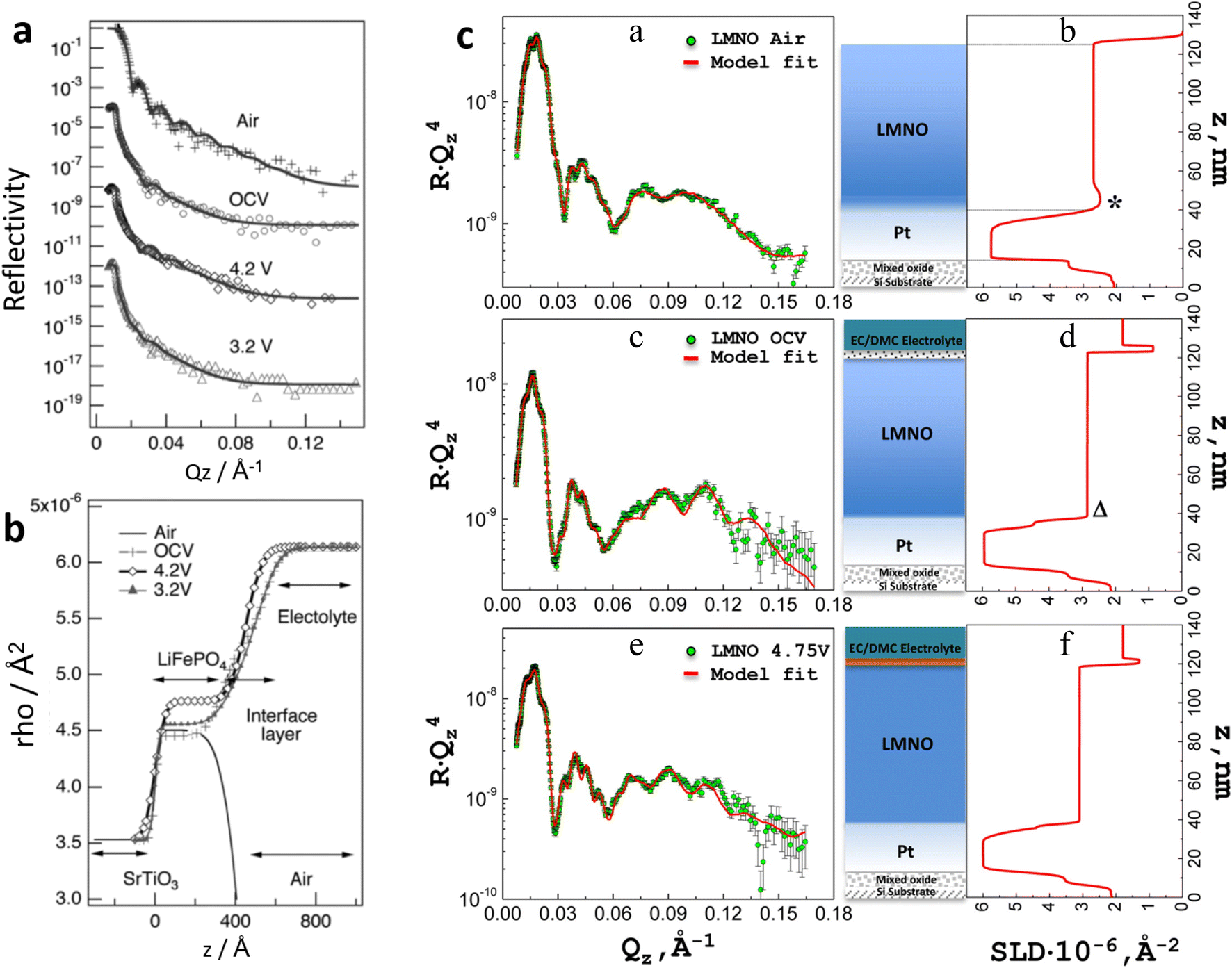 | ||
| Fig. 18 (a) In situ NR spectra and (b) scattering length density profiles of a LiFePO4 (100) film in air, after being soaked in the electrolyte, and during the first charging and discharging conditions. Reproduced with permission from ref. 91. Copyright © 2010, J-STAGE. (c) Reflectivity profiles collected in situ from the LMNO film (a, top left) in air, (c, middle left) at the OCV, and (e, bottom left) charged to 4.75 V. Corresponding SLD plots representing the film thickness (b, top right; d, middle right; f, bottom right). The schematics in the middle represent the layers formed from the silicon substrate upwards in the vertical direction. Reproduced with permission from ref. 92. Copyright © 2014, American Chemical Society. | ||
Browning et al. conducted a very similar experiment to study the interface between a LiMn1.5Ni0.5O4 (LMNO) cathode and an EC:DMC:LiPF6 electrolyte.92 They found that a 3.3 nm interfacial layer with an SLD of 0.87 × 10⁻⁶ Å−2 is formed between the cathode and the electrolyte at the OCV stage (Fig. 18b). The relatively low SLD of this layer was argued to be consistent with a Li-rich composition likely originated from the Li in the LiPF6 salt. While the thickness of this interfacial layer was slightly reduced by 2 nm when the cell was charged (at 4.75 V), its SLD increased to 1.3 × 10⁻⁶ Å−2, which was attributed to a possible combination of loss of Li due to delithiation and, less evidently, a gain of Pt from the anode or F from the electrolyte. The ability to probe multiple layers simultaneously with NR allowed the researchers to also investigate other interfaces within the system such as the ones between the cathode and the Pt current collector, and the Pt (cathode current collector) and Si substrate. At the former interface, it was found that some of the Li in the cathode diffuses into the Pt current collector forming a 14.46 nm LMNO/Pt interfacial region between the cathode and current collector. At the OCV stage, this region contracts by more than half of its size and its SLD increases by almost 56%, which the researchers argued could be explained by Li leaving this interface and diffusing into the bulk LMNO.
Minato et al.94 have conducted the same type of in situ NR experiment on one of the most widely used cathode material for Li-ion batteries, LiCoO2, and also reported the formation of an interfacial layer between the cathode and the electrolyte (d-EC:d-DMC:LiClO4). This interfacial layer had relatively high roughness of 25.9 nm, indicative of a diffuse interface, which was attributed to the reaction between the LiCoO2 surface and the electrolyte. The SLD of this interfacial layer was 8.51 × 10⁻⁶ Å−2 which the researchers interpreted to be an indication that its composition was dominated by poly(ethylene oxide) since, out of all the species known to be present in this type of interfacial layer (Li2CO3, LiOD, LiCL, LiOCO2CD3, and (LiCO2CD2)2), it has the closest SLD (7.51 × 10⁻⁶ Å−2) to that of the interface. At the charge state (4.2 V), the SLD of this interfacial layer increased to 3.33 × 10⁻⁵ Å−2 which the researchers suggested could be indicative of the formation of inorganic species, Li2CO3, LiCL, LiOCO2CD3, and (LiCO2CD2)2, as their SLD's are all higher than that of the interfacial layer at the OCV state. Researchers also suggested that, if this interfacial layer is highly porous, its increase in SLD during delithiation could also be caused by the adsorption of electrolyte, which has a high SLD of 5.54 × 10⁻⁵ Å−2. At the discharge state, the SLD of the interfacial layer decreased slightly, but perhaps more relevantly, its thickness decreased from 48.8 nm at the charge state to 35.6 nm which is closer to the original 30.6 nm at the OCV state (Fig. 19). This expansion and contraction of the interfacial layer at different states of charge was clear evidence of its dynamic behaviour.
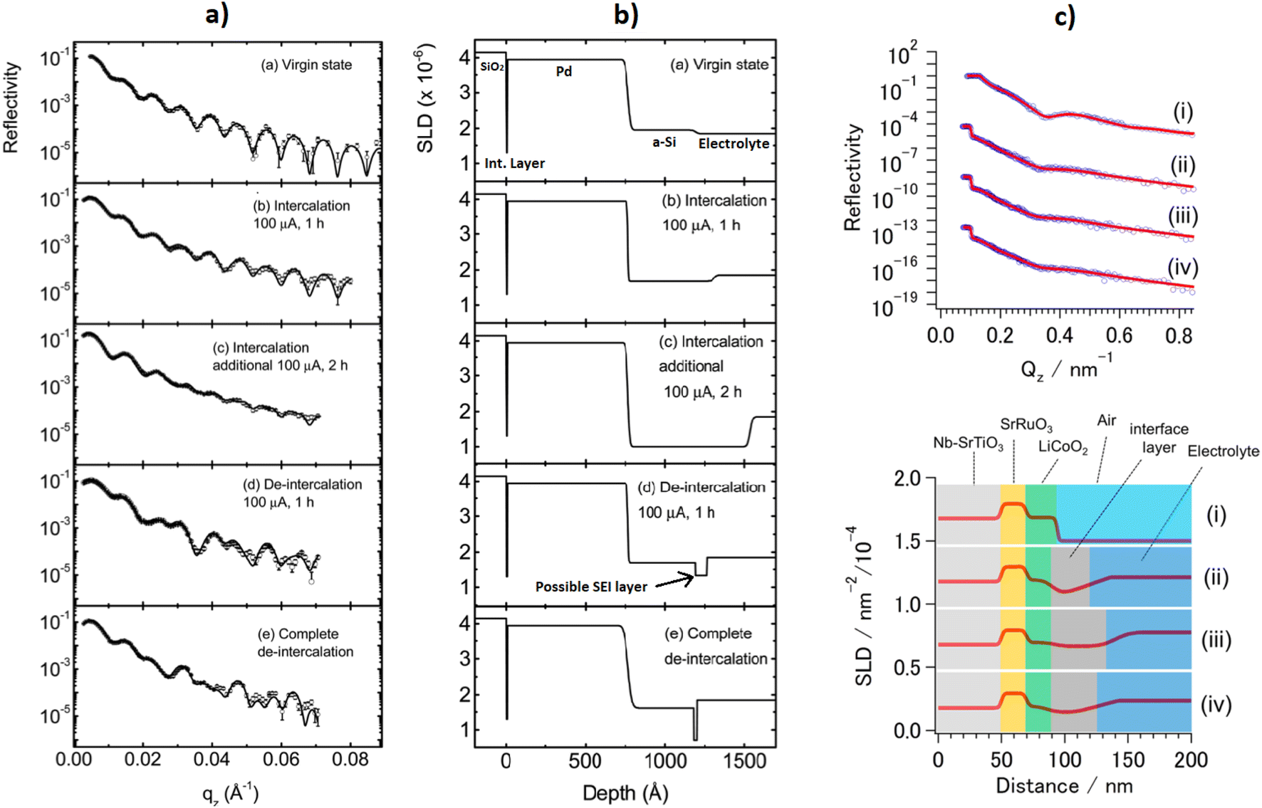 | ||
| Fig. 19 (a) Neutron reflectivity profiles and corresponding SLD profiles (b) of amorphous Si at different stages of charge. Reproduced with permission from ref. 93. Copyright © 2013, Royal Society of Chemistry. (c) Neutron reflectivity (top) and analysed SLD (bottom) from (i) the as-prepared sample (LiCoO2(104)/SrRuO3(100)/Nb–SrTiO3(100)), (ii) the sample after immersion in electrolyte (1 M LiClO4 in deuterated EC:DMC (vol. 1:2)), (iii) the sample after Li+ extraction at 4.2 V (vs. Li+/Li), and (iv) sample after Li+ insertion at 3.3 V (vs. Li+/Li). The blue dots and red curves in (c) correspond to experimental and fitted data, respectively. The neutron reflectivity in (ii), (iii), and (iv) and SLD values in (i), (ii), and (iii) are shifted by a fixed y-axis offset for clarity. Reproduced with permission from ref. 94. Copyright © 2016, American Chemical Society. | ||
As with most neutron experiments, when doing in situ or operando NR battery studies it is crucial to minimise the incoherent scattering of hydrogenous materials to obtain high quality data. Since most battery architectures contain organic electrolytes it is good practice to use deuterated versions of these (e.g. Hirayama et al. and Minato et al.). This often comes at the expense of electrochemical performance, so it is important to optimise the level of deuteration in the system to obtain a good neutron signal without substantially compromising the electrochemical performance of the device.
Since NR can be used to track the changes in size and composition caused by Li intercalation of the different layers within the battery architecture, it is particularly useful to investigate silicon anodes. This is because understanding the mechanisms behind the major drawback of this promising high theoretical capacity type of anode, its substantial volumetric change during intercalation and consequent structural fragmentation, can lead to unlocking its full potential. Jerliu et al., for example, demonstrated that the thickness of an amorphous Si (a-Si) anode in a SiO2/Pd/Si/PC:LiClO4 cell increases from 425 to 769 Å after full lithiation.93 They also observed the insertion of Li in the a-Si layer which was evidenced by its decrease in SLD from 1.95 × 10⁻⁶ to 1.00 × 10⁻⁶ Å−2. Researchers also reported that the formation of a layer, tentatively labelled as the SEI, was detected only during the delithiation step for which the corresponding data could only be fitted by adding a 74 Å layer with an SLD of 1.33 × 10⁻⁶ Å−2 to the model. Upon further delithiation this additional layer decreased its thickness and SLD to 20 Å and 0.71 10−6 Å−2, respectively, however no explanation for this trend was offered and further investigation was suggested instead. As expected, the thickness of the a-Si layer decreased from 769 Å at full lithiation to 414 Å at full delithiation evidencing the highly expandable and contractable nature of a-Si. Moreover, its SLD increased from 1.00 × 10⁻⁶ Å−2 to 1.61 × 10⁻⁶ Å−2, respectively, which is expected as Li leaves the a-Si anode. However, the fact that the SLD does not increase up to its original non-cycled value of 1.95 × 10⁻⁶ Å−2 is evidence of a partial irreversible change in composition which typically indicates a permanent decrease in capacity for subsequent cycles.
NR's utility in investigating lithiation kinetcis in Si anodes has also been demonstrated by Seidlhofer et al. who did an NR operando study of a crystalline silicon (c-Si) cell with a (c-Si)/SiO2/surface layer product of the reaction between SiO2 and the electrolyte (SL)/LiPF6:EC:DEC electrolyte (El) architecture (Fig. 20).95 They found that a previously unreported 5.5 nm Li-enriched layer forms on top of the SL during the early stages of the first lithiation. This layer was found to have a maximum of 13% Li enrichment with respect to the El, and to disappear after 100 minutes of lithiation at 25 μA. They also reported the dissolution and transformation of the native SiO2 into a Li-rich layer, which the authors suggested to be likely comprised of Li2O or LixSiOy, after 365 minutes of lithiation. Contrary to various previous reports of similar Si-anode-based architectures investigated with other characterisation techniques, Seidlhofer et al. also found that Li penetration is not homogeneous throughout the c-Si electrode. Instead, two different main regions form within c-Si during full lithiation. Near the electrolyte there is a strongly lithiated ∼18 nm skin region with a minimum SLD is −0.08 × 10⁻⁵ Å−2, corresponding to a maximum amount of Li x ≈2.5 in LixSi, which gradually increases with distance towards the opposite end of the c-Si layer. The latter is evidence that there is a gradual decrease of Li with distance away from the electrolyte until a second ∼32 nm bulk region with a relatively constant SLD of 1.8 × 10⁻⁵ Å−2, corresponding to a Li amount of x ≈ 0.1, is detected. Researchers suggested that the internal stress induced by the substantial volume changes of the anode during lithiation could be the main reason for the formation of these two different regions. Upon delithiation researchers found that a finite amount of Li, x ≈ 1.1, remains in the skin region and that a new surface layer, suggested to be the SEI, forms at the electrode/electrolyte interface. Both of these findings are in agreement with those of Jerliu et al. previously discussed. The same skin and bulk regions formed again during a second lithiation cycle in which the alleged SEI also disappeared after 400 minutes. The second cycle followed a similar path to the first including the velocity of lithiation, 2 × 10⁻¹² m s−1, and delithiation, 7 × 10⁻¹² m s−1, with the most noticeable difference being that the bulk region had a higher thickness, 76 nm, during second lithiation. A similar experiment was conducted by the same research group in which a successive growth of the lithiation zone was observed throughout four cycles. The coulombic efficiency loss was directly correlated to the formation of a layer that dissolves into the silicon layer suppressing lithium insertion. It was also found that inital parasitic side reactions occur after which current losses of less than 5% can be achieved.96
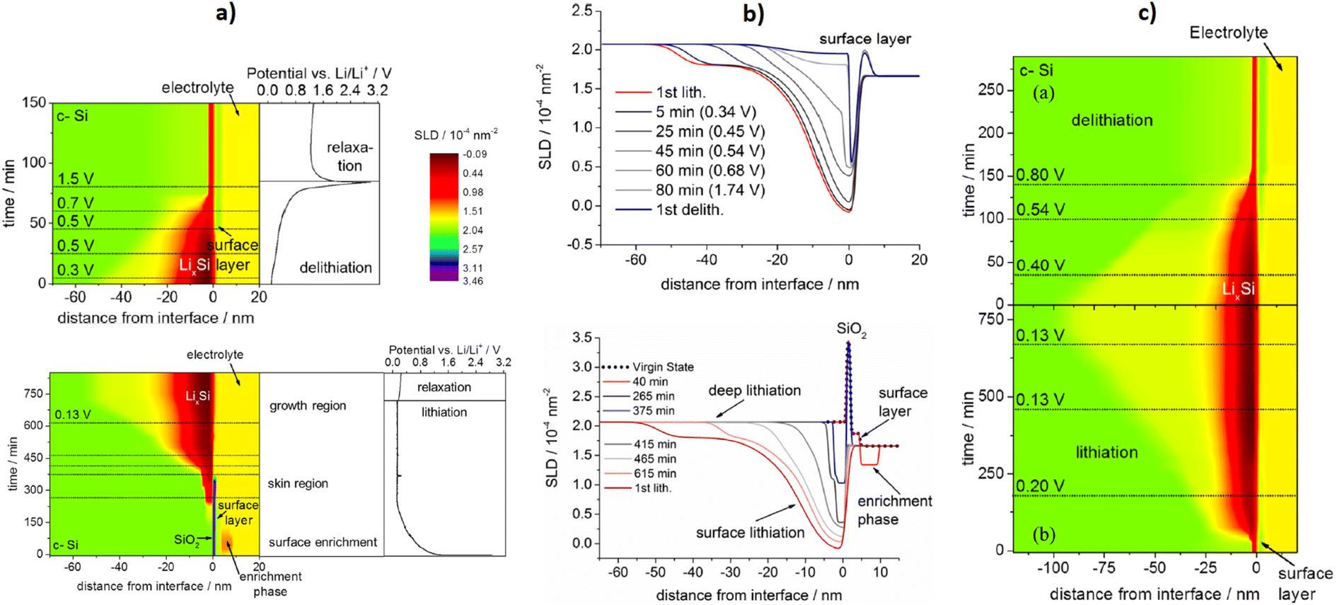 | ||
| Fig. 20 (a) Evolution of the scattering length density profile of crystalline Si as a function charge (bottom) and discharge (top). (b) Some SLD profiles taken at specific voltages (top) and times (bottom). (c) Evolution of the SLD profile during the second cycle. Reproduced with permission from ref. 95. Copyright © 2016, American Chemical Society. | ||
3.5 Inelastic and quasielastic neutron scattering
The techniques discussed so far involve elastic scattering in which there is negligible energy transfer between neutrons and the sample. Inelastic neutron scattering (INS), which involves an energy and momentum exchange between neutrons and the sample, is a powerful tool that can probe the dynamics of a system. As the energies of thermal neutrons are comparable to excitation energies in materials, INS can provide insight into processes including molecular vibrations, rotations, lattice vibrations (phonons), and diffusion. Quasielastic neutron scattering (QENS) refers to scattering that involves a small energy exchange, due to processes with a distribution of energies such as translation, as opposed to discrete energy steps, such as vibration. Therefore, these scattering experiments can probe very different dynamic phenomena depending on the energy transfer (Fig. 21), and we will discuss which experiments are most relevant to battery characterisation in this section.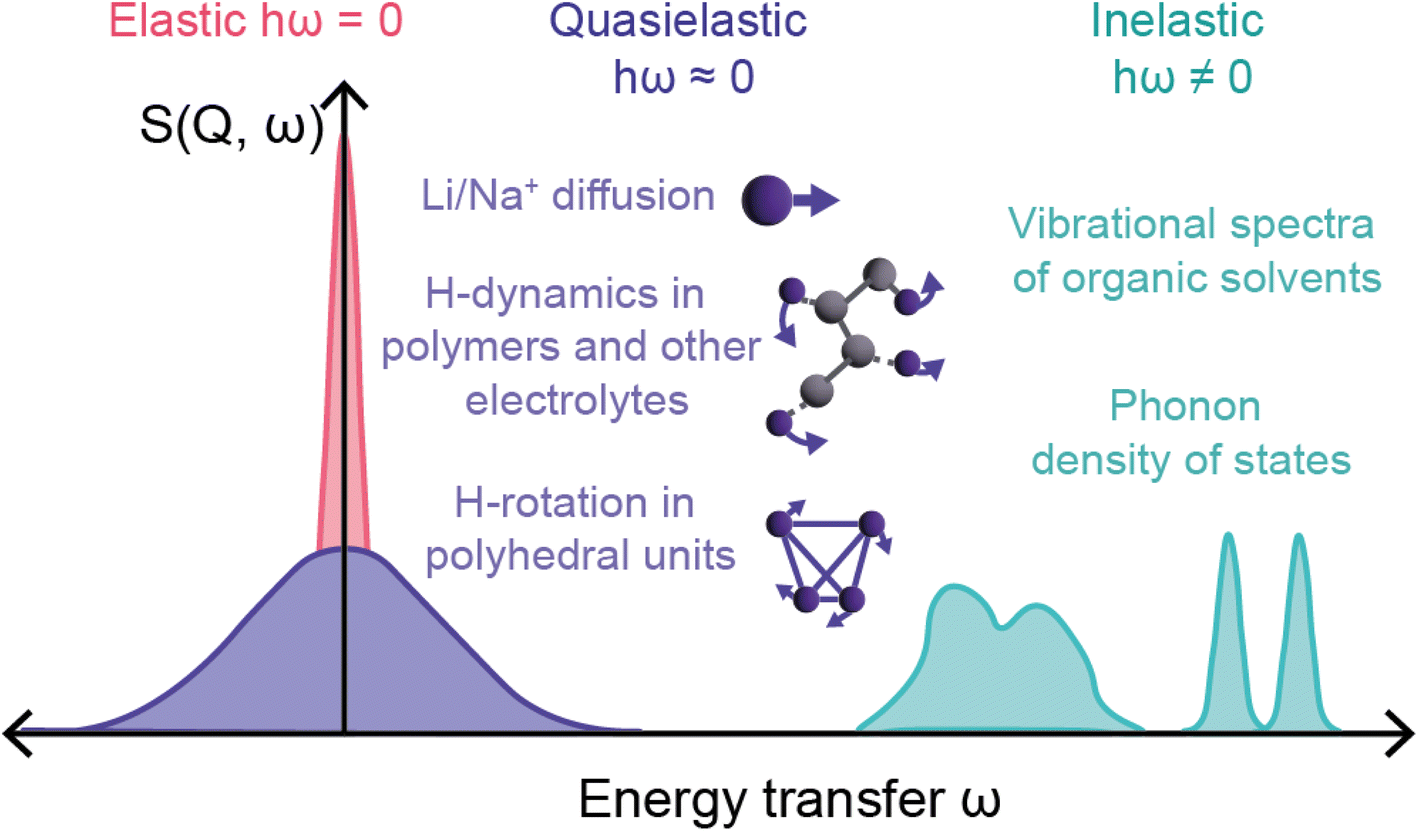 | ||
| Fig. 21 Diagram showing representations of elastic, quasielastic, and inelastic scattering signals from various dynamic processes that can be probed in battery systems. | ||
The neutron scattering length, b, for each element is isotope dependent. In elastic scattering experiments the interference of coherent scattering from a sample gives structural information, and this is from the average scattering length of the nuclei b. The incoherent component is a result of variation in b due to isotope differences, including the difference in nuclear spin orientation. For elastic scattering, the incoherent scattering is isotropic, and manifests as a background contribution. However, for inelastic scattering the incoherent scattering is very significant.
The correlation function, G(r,t), represents the probability of finding a particle at time t and position r, given a particle is at position r = 0 at time t = 0. Fourier transforms with respect to time and space yield the dynamical scattering function S(Q,ω). Similarly, the self correlation function, Gs(r,t), is the probability of finding the same particle at position r,r = 0 and time t, t = 0. Fourier transforms yield the incoherent scattering function Sinc(Q,ω). The measured scattering is a combination of both coherent and incoherent contributions, that describe the dynamics of collective and individual nuclei, respectively.
Thus, the incoherent inelastic scattering can provide information on ionic diffusion, as well as rotational diffusion. The incoherent scattering cross section varies between isotopes, and is extremely large for hydrogen (σinc = 80.26 barn) compared to deuterium (σinc = 2.05 barn). As a result, the technique is exceptional at probing hydrogen dynamics, and contrast matching experiments are very effective. On the other hand, samples containing hydrogen are often deuterated for elastic measurements to minimise the incoherent background contribution from hydrogen.
QENS can probe dynamics including long range diffusion on the 10−7 to 10−13 s time scale. This makes it complimentary to muon spectroscopy which probes slower processes, and NMR which has limitations in samples containing paramagnetic ions. Compared to other techniques that probe diffusion such as electrochemical impedance spectroscopy (EIS) and galvanostatic intermittent titration technique (GITT), QENS (and muons) gives true bulk diffusion information independent of surface and grain boundary effects. QENS data can also provide information on the diffusion mechanism, and is therefore a technique that can probe both the temporal and spatial aspects of diffusion.
INS and QENS are useful techniques for battery characterisation, as they can probe the many dynamic processes involved in battery function. INS is particularly useful in understanding the dynamics of polymer electrolytes.97 QENS is mainly suited to probing ionic diffusion in electrodes and electrolytes,98–101 and can also probe rotational dynamics in electrolyte materials.102,103 The main limitations of these techniques is that the measurements take a relatively long time and can require large samples. Currently, this time limitation precludes operando studies.
The vibrational structure of a sample can be understood by measuring the phonon density of states in an INS experiment. Benedek et al. used this experiment on the active cathode material LiFePO4 (LFP) to understand the differences between the surface and bulk of LFP.104 The authors achieved this by preparing platelet-shaped particles of different sizes with their surface/bulk ratio ranging from 0.4–11%. The differences in DOS could therefore be linked to the nature of the surface structure. The platelets were made to have a majority (010) facet surface, as the Li transport occurs along the [010] direction making this the important surface for interface effects (Fig. 22a–c). In addition, the particles were treated as active material and had a carbon coating applied.
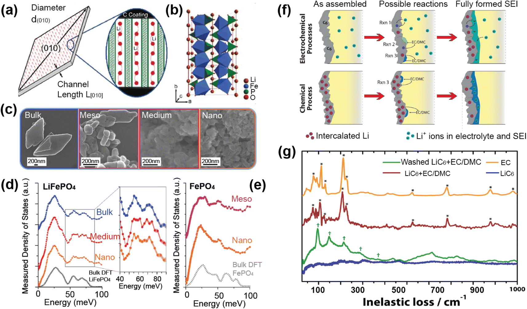 | ||
| Fig. 22 Platelet shape (a), structure (b), and SEM images (c) of LiFePO4 (LFP) particles with the INS spectra of the lithiated and delithiated samples shown in (d) and (e), respectively. Reproduced from ref. 104 with permission from the Royal Society of Chemistry. (f) Schematic of the different strategies for forming an SEI along with the types of reactions involved. (g) Inelastic neutron scattering of EC, LiC6 + EC/DMC, and washed LiC6 + EC/DMC. Asterisks indicate major peaks ascribed to EC and daggers correspond to peak locations of poly(ethylene oxide)-type vibrations. Reprinted with permission from ref. 105 Copyright (2015) American Chemical Society. | ||
By performing INS measurements the authors obtained the phonon density of states (PDOS) of three different sized lithiated samples (Fig. 22d) and two delithiated samples “Nano” and “Meso” (Fig. 22d). The PDOS of the lithiated samples showed a merging of peaks with decreasing particle size, while no change was seen for the delithiated samples. They concluded that the changes are related to the Li vibrations. DFT calculations were used to show the impact of different surface terminations on the Li–O bond length, revealing that the Li–O bond is shorter for the vacuum terminated and carbon terminated surfaces. This impact of the surface on the Li–O bonding is consistent with the changes in the PDOS which showed a shift to higher energy vibrations from the stronger Li–O bonds. The INS coupled with DFT calculations were able to show the impact of surface terminations on the Li–O vibrations and therefore the Li diffusion, and the role that coatings can have in tuning the bonding character at the surface.
The SEI is a vital component of a working battery system, however it is perhaps the most challenging in terms of characterisation of its formation, structure, and evolution. The interface usually isn't air-stable which means ex situ experiments are often not possible. Neutrons are ideal for probing buried interfaces as they can penetrate relatively far into materials. As shown in the previous section, SANS is a useful technique to probe the SEI, and an in situ experiment could extract information about the formation and nature of the SEI. A limitation of this experiment was that the chemical species present were unknown and had to be inferred by SLD changes.
Sacci et al. studied the formation of an SEI on lithiated graphite (Fig. 22f) using both SANS and INS techniques.105 Optical spectroscopy was unable to obtain chemical information from the sample due to the strong graphite signal, in contrast INS is extremely sensitive to hydrogen in organic components so proved to be a unique tool in this case. The INS measurements were carried out on the VISION spectrometer at the SNS. The lithiated graphite alone showed a small background signal, as expected, while the sample soaked in EC/DMC showed a signal primarily of the organic EC solvent (Fig. 22g). The measurement from the washed sample with excess EC removed should correspond to the SEI component, and they found that the spectra exhibited vibrational features similar to polyethylene oxide (PEO). They concluded that the SEI is organic and polymeric in nature, and further analysis of the contrast-matching SANS experiment was consistent with this.
QENS experiments probe dynamics that aren't associated with discrete energies. In the battery area these dynamics include ionic diffusion and rotational or relaxation dynamics in electrodes and electrolytes. For probing ionic diffusion, QENS is an extremely powerful tool for extracting the diffusion coefficient and information on the mechanism for timescales in the range 10−7 to 10−13 s. While the incoherent scattering gives direct information on diffusion, as this component is related to the time-dependant self-correlation function, not all atoms of interest have a large incoherent scattering cross section. However, the coherent scattering can also be used to understand diffusion, and there are some examples of this.108–110 Sodium has a reasonable incoherent scattering cross section (1.62 barn) and sodium ion diffusion in the cathode material Na0.8CoO2 was investigated using QENS measured on OSIRIS at ISIS, in combination with diffuse X-ray scattering and ab initio molecular dynamics simulations.101
In this study the authors observed QENS broadening from the onset of diffusion (Fig. 23a) and they correlated the temperature dependence of this broadening to the formation of disordered phases identified using diffuse scattering (Fig. 23b). By resolving the Q-dependence of this line width the diffusion mechanism was identified as translational diffusion. Further analysis of the data suggested that hopping between the 2d and 2b sites is the dominant diffusion process, with a diffusion coefficient of 1.4(2) × 10−7 cm2 s−1. This diffusion rate was consistent with that obtained using PITT measurement, but there was a large discrepancy with the rate obtained using EIS measurement (10−10). This study demonstrates the power of QENS in extracting the ionic diffusion rate and mechanism in an electrode material.
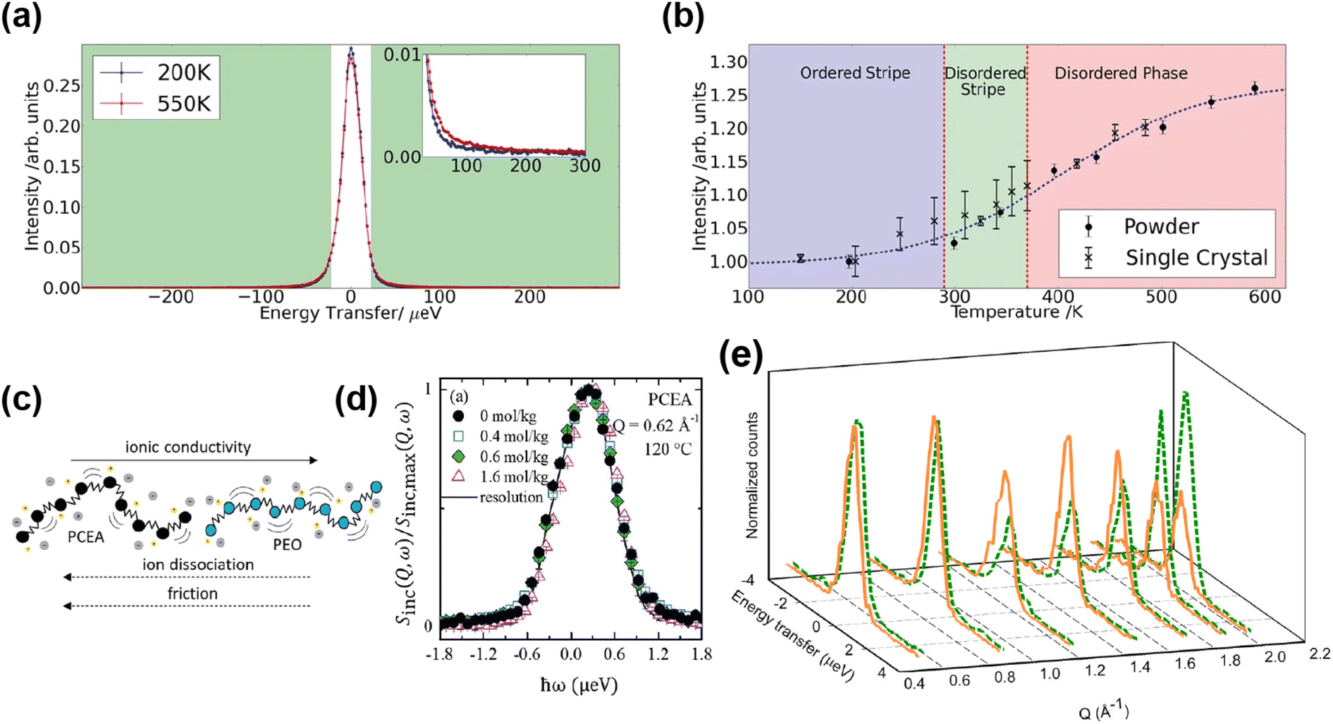 | ||
Fig. 23 (a) QENS spectra from Na0.8CoO2 at T ![[2 with combining tilde]](https://www.rsc.org/images/entities/char_0032_0303.gif) 00 K (blue) and T 00 K (blue) and T ![[5 with combining tilde]](https://www.rsc.org/images/entities/char_0035_0303.gif) 50 K (red) integrated over Q. Inset shows increase in the quasi-elastic region. (b) QENS intensity integrated over Q and energy transfer as a function of temperature for the powder and single-crystal samples of Na0.8CoO2.101 Copyright 2018, CC BY 4.0. (c) Representation of PEO and PCEA polymers. (d) Normalized incoherent structure factor, Sinc(Q,ω)/Sinc,max(Q,ω), in the frequency domain, plotted as a function of energy, hω, at Q = 0.62 Å−1 and 120 C. Reprinted with permission from ref. 103 Copyright (2020) American Chemical Society. (e) QENS spectra recorded for 7Li(11BD4)0.75I0.25, at 300 K, without (orange solid line) and with (green dashed line) the application of a potential (f = 1 kHz, U = 3 V, and I = 0.4 mA).107 Reprinted with permission from ref. 107 Copyright 2013 American Chemical Society. 50 K (red) integrated over Q. Inset shows increase in the quasi-elastic region. (b) QENS intensity integrated over Q and energy transfer as a function of temperature for the powder and single-crystal samples of Na0.8CoO2.101 Copyright 2018, CC BY 4.0. (c) Representation of PEO and PCEA polymers. (d) Normalized incoherent structure factor, Sinc(Q,ω)/Sinc,max(Q,ω), in the frequency domain, plotted as a function of energy, hω, at Q = 0.62 Å−1 and 120 C. Reprinted with permission from ref. 103 Copyright (2020) American Chemical Society. (e) QENS spectra recorded for 7Li(11BD4)0.75I0.25, at 300 K, without (orange solid line) and with (green dashed line) the application of a potential (f = 1 kHz, U = 3 V, and I = 0.4 mA).107 Reprinted with permission from ref. 107 Copyright 2013 American Chemical Society. | ||
The Na-ion diffusion mechanism was also investigated in the amorphous phase of Na2Si2O5 using a combination of QENS and ab initio and force-field molecular dynamics simulations.99 The data were modeled by a jump-diffusion model with a mean jump length of about 3 Å, residence time of 9 ps, and diffusion coefficient value of (16 ± 11) × 10−10 m2 s−1 at 748 K. The crystalline phase is a poor ionic conductor, and the QENS results were able to shed light on why by revealing that the diffusion pathways are dependant on different orientations of silicon polyhedral units that are rigid in the crystalline phase.
Similarly, magnesium borohydride, a potential Mg-ion conductor, was studied using QENS and this system also exhibits higher conductivity in the amorphous phase.111 PDF measurements showed the short range structure to be the same in both samples, and that the 3D diffusion networks are likely still present in the amorphous phase. QENS is sensitive to the H motion in the BH4 units, and so the H-dynamics in this system were probed in this case. The measurements indicated a greater rotational mobility of these units in the amorphous phase relative to the crystalline (Fig. 23e). This indicated that the so-called “paddle-wheel” mechanism, where diffusion is supported by the rotating BH4 units, is the reason for the higher observed conductivity in the amorphous phase relative to the crystalline.
QENS is able to probe segmental dynamics in polymer electrolytes.110 The polymers PEO and poly(carboxyethyl)acrylate (PCEA), both mixed with different concentrations of lithium bis(trifluoromethane)sulfonimide (LiTFSI) salt, have been compared using QENS and impedance spectroscopy.103 The QENS signal is dominated by the H in the polymers, so the mean-square displacement of the H in each sample could be determined and related to the diffusion parameter which decreases with increasing salt concentration. From this data the authors calculated the monomeric friction coefficient, which is a measure of the segmental rate of relaxation of the polymer. They found that the segmental dynamics are about 100 times slower in PCEA than in PEO, and this is one of the main factors in determining ionic conductivity. This can in part explain the difference in conductivity between the two polymers, and they built a simple expression that describes the dependence of ionic conductivity on friction, salt dissociation, and salt concentration (Fig. 23c and d).
QENS can also provide information on the dynamics in other electrolytes including solvent-in-salt,112 water-in-salt,113 and solid state electrolytes.102,107 For example, González et al. studied the dynamics in water-in-salt electrolytes using QENS.113 The translational diffusion of water in the electrolytes was obtained and compared to that from MD simulations. Deuterated water was used strategically and both the incoherent and coherent scattering analysed in order to separate the dynamics in the water and ionic framework.
The ion dynamics in the potential solid-state electrolyte LiBH4:LiI was studied using DFT and QENS measurements with and without an applied bias potential of 3 V.107 Again, both the protonated and deuterated systems were measured and this allowed the dynamics of the H and the Li to be separated. The QENS results indicated long range diffusion of Li+, with jump lengths of one unit cell for the HT hexagonal phase, compared to a shorter length (2 Å) at 300 K. The shorter length could correspond to a jump process of Li+ interstitials to an intermediate lattice site, and this is consistent with the DFT results. The QENS spectra – both the elastic line intensity and broadening – depended heavily on the application of the bias, shown in Fig. 23e, and they found that the application of the bias potential increases the diffusion constant by a factor of 2.
Although the diffusion probed using QENS is usually thermal diffusion with no applied potential, these experiments are still useful in lieu of operando measurements. However this last example, in which the QENS measurement was performed using a specially designed aluminum flat cell with the application of a potential to the solid electrolyte, showed that the diffusion coefficients almost doubled with the 3 V potential compared to without. This demonstrates the possibility and utility of this type of measurement, and moving towards measuring the dynamics in operating cells will take full advantage of these techniques in the battery area.
3.6 Neutron imaging
Neutron imaging is a unique neutron technique because it directly probes features in real space. The term imaging refers to a number of separate techniques; traditional imaging known as radiography is simply the image detected by transmitting neutrons through an object, analogous to the X-ray imaging of a broken bone, and tomography is the reconstruction of many radiographs of the object at different orientations to give a 3D image. These techniques give spatial information on the chemical composition in a sample, but not the structure. Bragg edge imaging, used alone or as a contrast technique, can provide information on the structures contained in an object.Radiography is the most traditional form of imaging, in which the neutrons are transmitted through an object, and a 2D image is obtained by detecting the transmitted neutrons. The transmission is described by the Beer–Lambert law and depends on the incoming beam, sample density, and total microscopic cross section which is both the microscopic absorption and scattering cross section. By analysing this it is possible to extract the attenuation across the sample and information on the chemical composition.114 Tomography is the reconstruction of many radiographs of the sample at different orientations to give a 3D image that represents the attenuation coefficient distribution. The reconstruction is not a simple process, involving complex mathematical algorithms that can produce artefacts.115 Finally, Bragg edge imaging can provide information on crystalline structure.116 This technique utilises the fact that neutrons can be scattered by the sample, as well as absorbed. If an object contains crystalline components, the neutrons will be diffracted when Bragg conditions are satisfied. As neutrons are diffracted the attenuation will increase, or transmission decrease, until the Bragg conditions are not satisfied at which point the transmission will abruptly increase. This rapid increase in the transmission spectrum as a function of energy produces saw-tooth features known as Bragg edges. These edges correspond to lattice planes, and can be fitted to provide information on the crystal structure. The technique is also known as energy resolved neutron imaging as the transmission is detected as a function of neutron energy.
Neutron imaging directly probes features in real space, and the instrument set up reflects this in the geometry and detectors. In most cases, an imaging experiment will measure the transmitted intensity, so the detector will be placed in the beam path after the sample. The resulting resolution depends on optimisation of the beam and the detector system, but the contrast and transmission depends on the composition of sample. Spallation sources have advantages for this technique; wide wavelength spectrum gives best flux conditions in transmission geometry, and the TOF method gives high energy resolution.
Although X-ray imaging is a more widely known technique, neutrons bring certain advantages to imaging, particularly in relation to battery characterisation. X-ray attenuation is proportional to the number of electrons but this is not the case for neutrons, and some of the lightest elements have the highest attenuation. For example, H and Li have high attenuation making neutron imaging sensitive to organic matter as well as Li content. Since attenuation depends strongly on the isotope, isotopic substitution can be used to enhance contrast. Furthermore, due to their neutral charge, neutrons can penetrate materials that X-rays can't, so sample containers, electrochemical cells, and commercial batteries can be studied more effectively with neutrons. The main battery-relevant uses for neutron imaging are observing relatively large features in working batteries, such as electrode expansion and cracking, structural degradation and gas evolution. Imaging is also useful in tracking Li distribution and phase distribution across electrodes and entire cells, this is important as inhomogeneity is a common issue that impedes performance.
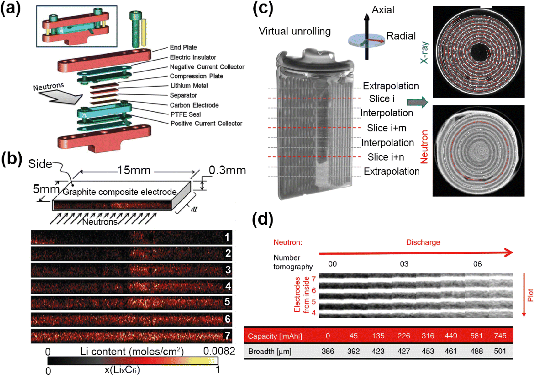 | ||
| Fig. 24 (a) Diagram showing the custom cell built by ref. 117 for neutron imaging experiments. (b) Time-resolved radiographs showing Li distribution in the graphite electrode during the first discharge. Reprinted from ref. 117 Copyright 2012, with permission from Elsevier. (c) Reconstructed tomograms from neutron and X-ray CT along with examples of sections extracted following virtual unrolling of the reconstructions. (d) Image shows cut-outs of virtual unrolled multilayer sections of the measured neutron tomograms at different states of charge from the pristine state to the partly discharged state, with the change in Li intensity through battery shown on the right.118 Reprinted with permission copyright 2020, CC BY. | ||
Another phenomenon that neutron imaging is able to observe is the formation of bubbles as gas evolves from cycling, and Michalak et al. used radiography to observe gas evolution from cells with combinations of LiNi0.5Mn1.5O4 (LNM), LiFePO4 cathodes and graphite, Li4Ti5O12 anodes.121 From imaging measurements on the ICON beamline at SINQ the amount of gas evolved on cycling could be calculated, and different cell combinations were used to understand the origins of the gas produced. It was concluded that gas evolution occurs from the SEI formation on graphite, and oxidation of the electrolyte on the LNM cathode. The study also found that contamination of SEI formation on graphite by LMN increases gas evolution. Neutron imaging provides a unique opportunity to observe and understand the origins of gas evolution in batteries, a process that can cause damage to the battery components and safety concerns.
Tomography can provide enormous insight into the many processes that occur in working batteries on cycling, including those associated with operation and degradation. Ziesche et al. carried out combined X-ray and neutron tomography of commercial Duracell batteries with LiMnO2 cathode, collecting neutron imaging data on CONRAD-2 at HZB.118 The volume changes, cracking, and other changes throughout the battery on cycling were tracked. Consumption of excess electrolyte was observed and is thought to be due to electrolyte reaction to form the interface layer, as well as filling the emerging cracks in the cathode as it expands upon lithiation. Both measurements indicated that the state of charge (SoC) has a major impact on the cathode volume expansion; this is caused by Li insertion in the LixMnO2 structure and significant electrode cracking. Both discharge processes showed a linear cathode volume expansion with an equal volume increase for similar C-rates.
Neutron imaging enables the direct detection of the Li diffusion from the Li metal electrode to the LixMnO2 electrode. In order to overcome the challenges of analysis of the spiral-wound electrode, Ziesche et al. applied a virtual unrolling of the datasets which allowed them to track the change in Li distribution across the electrode with cycling (Fig. 24c). Heterogeneous intensity change over the cathode indicated higher Li intercalation at the outer electrode side (Fig. 24d), which could be explained by the higher compression of the material at the inner side caused by the electrode roll up during cell manufacturing. The lower compression at the outer side allows easier Li intercalation and less resistance for electrode expansion. Lithiation was not detected at the inner and outer cathode endings, which was caused by the Li metal electrode ending before reaching the cathode end. This study demonstrates the power of neutron tomography in observing Li intercalation and the associated impact on all battery components.
Bragg edge imaging, unlike radiography and tomography, can provide information on structure and phase distribution in the battery. Kino et al. performed an in situ Bragg-edge imaging experiment of commercial 18650 LIB batteries at different states of charge.119 Radiographs showed the migration of the electrolyte with charging, and they obtained spatially resolved Bragg-edge spectra for each sample (Fig. 25a and b). These revealed that the dominant negative electrode phases are graphite, LiC12, and LiC6 for the discharged, intermediate, and charged states, respectively. For the positive electrodes, Li0.9Ni0.8Co0.2O2, Li0.7Ni0.8Co0.2O2, and Li0.5Ni0.8Co0.2O2 were used to fit the spectra.
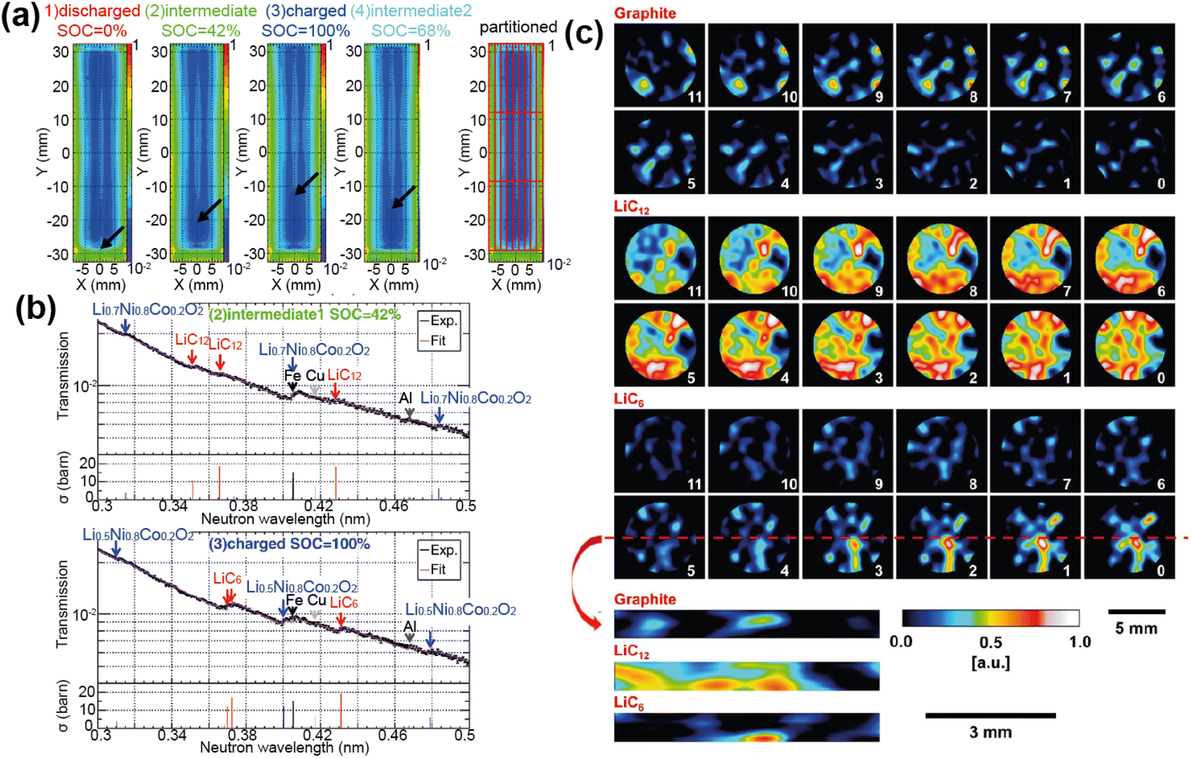 | ||
| Fig. 25 (a) Transmission images of the four charge states, arrows indicate electrolyte migration. (b) Examples of the fits of the transmission spectra, with arrows indicate the positions of the Bragg edges for corresponding materials. The graph below each transmission spectrum indicates the cross section at the Bragg edge of crystalline materials on the basis of the calculation of the coherent elastic scattering. The cross sections of the graphite and LiC6 are scaled 12 and 2 times larger, respectively. Reprinted from ref. 119 Copyright 2016, with permission from Elsevier. (c) Maps of Bragg edge heights of graphite, LiC12 and LiC6 phases for horizontal (upper) and vertical slices (lower) for electrode-1 at ca. 33% SoC. The slices show an inhomogeneous distribution of the phases where black/blue represent the absence or a low proportion of the lithiation phase and red/white a high proportion. The horizontal slice number 0 was closest to the lithium-metal counter-electrode, i.e., with increasing slice number, the distance from the Li-metal electrode.120 Copyright 2020, CC BY. | ||
A recent example on combined tomography and Bragg-edge imaging was reported by Ziesche et al. who studied directional ice-templated (DIT) graphite electrodes at various stages of lithiation using the IMAT beamline at ISIS.120 DIT preparation results in elongated channel-like pores in the electrode structure that improve performance by promoting uniform Li concentration throughout a relatively thick electrode. The 4D data they obtained was a tomographic reconstruction with each voxel containing wavelength-dependent attenuation coefficients of each material component in terms of Bragg edges. Radiographs revealed air bubbles in some of the electrodes and the Bragg-edges for graphite, LiC12, and LiC6 were visible in the electrodes. These could be quantified and the shifts in the edges corresponding to changes in lattice parameters with lithiation was observed. Finally, the Bragg-edge tomography allowed the spatial distribution of each phase both across the electrode and through the electrode to be understood, shown in Fig. 25c. These showed an inhomogeneous distribution of the phases, and that in general the higher concentration of Li is seen closer to the Li source.
Inhomogenous Li distribution was also observed in pouch cells using a combination of energy-resolved neutron imaging, neutron diffraction, and X-ray radiography.122 Neutron imaging techniques are particularly effective when used in combination with other techniques including X-ray imaging, as they provide complementary information.
4 Muon spectroscopy
A muon is a subatomic, unstable particle from the lepton family which can be likened to a heavy electron (mμ ≈ 200 me) or a light proton (mμ ≈ 1/9 mp) depending on their charge. Muons for research are most typically produced at high-energy proton accelerators such as ISIS as one of the decay products from a short-lived positive pion,123 itself created from the collision of a proton with a graphite target. Muons produced from negative pions have found less common applications in research related to materials characterisation, however there has been increasing interest in the last decade on using negatively charged muons for elemental analysis. A pulse of spin-polarized positive muons are then directed towards a sample in which they are implanted inside, rather than scattered, generally stopping in proximity to an electronegative ion, often oxygen in battery materials. The muon spin then acts as a very sensitive local probe of its surrounding magnetic environment, and will become depolarized to an extent depending on the composition of its surroundings.By building an asymmetry picture of one of the muon's decay products, a positron which is emitted preferentially in the direction of the muon spin at the time of decay, one can deduce information about intrinsic material properties, both static and dynamic. The detection of the positrons with an asymmetrical spin distribution is practically achieved by positioning a forward and a backward detector on each opposing side of the sample (Fig. 26).
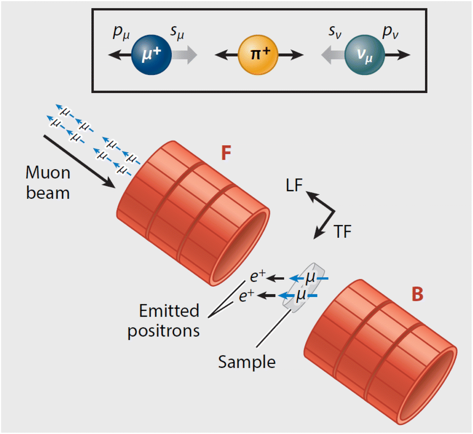 | ||
| Fig. 26 Geometry of the experimental set up for muon spectroscopy. Reproduced with permission from ref. 124. Copyright © 2019, Annual Reviews. | ||
The compatibility between the timescale of ionic site hopping in energy materials and the average muon lifetime (∼2.2 μs) affords the possibility to probe the dynamic processes within an array of battery materials, given the ion in question has a non-negligible nuclear magnetic moment.124 From a muon spectroscopy experiment one can obtain the Li/Na diffusion coefficient and activation energy to ionic motion, and deduce information about the diffusion pathway. The time scale of measurements is between 10−5 to 10−8 s, shifted to a slightly lower range from that of QENS (10−7 to 10−13 s), and hence allows the capability to study a different timescale of ionic motion.
Similar techniques such as nuclear magnetic resonance (NMR), which is a powerful, lab-based technique, can also be employed to study ionic dynamics, and may be preferable to μSR due to reduced cost and experimental simplicity. However, such measurements may be complicated by the presence of magnetic ions, commonly present in battery materials, which do not pose such an issue for μSR due to its simpler separation of electronic and nuclear contributions.
The volume-averaged nature of muon implantation means that gradiented or concentrated information may be lost in the total signal for some samples. However, this property can be used to an advantage to remove the often dominating effects from areas such as interfacial layers or grain boundaries, which can mask intrinsic material properties when using electrochemical techniques such as electrochemical impedance spectroscopy (EIS). Furthermore, sample inhomogeneity can be readily distinguished if certain areas have altered magnetic/diffusional properties (i.e. the sample surface125). The proportion of such environments can be simply extracted as the relative amplitude of each fitting function during data analysis. Furthermore, the ability to link information gained with other complementary techniques, such as neutron diffraction or EIS, allows the correlation of multiple viewpoints.
Given the plethora of techniques available to study diffusion processes in batteries, μSR offers an alternative with which to probe internal behaviour beneath the surface. Like neutrons, muons are a non-destructive probe and have the potential to study buried regions, such as the solid electrolyte interface, without disturbance. Such investigation can be applied to both solid- and liquid-based battery chemistries. Meanwhile, careful sample design and appropriate usage of both pulsed and continuous muon sources opens up capabilities to investigate a wide-range of battery phenomena as yet unstudied by μSR, such as depth-resolved diffusion, directionally dependent diffusion, or operando cells. Furthermore, the applicability of the muon to probe any dynamic ion with a non-zero nuclear magnetic moment, such as Na+,126 Mg2+,127 K+,128 and I−,129 remains an enticing opportunity for the characterisation of future battery technologies (Fig. 27).
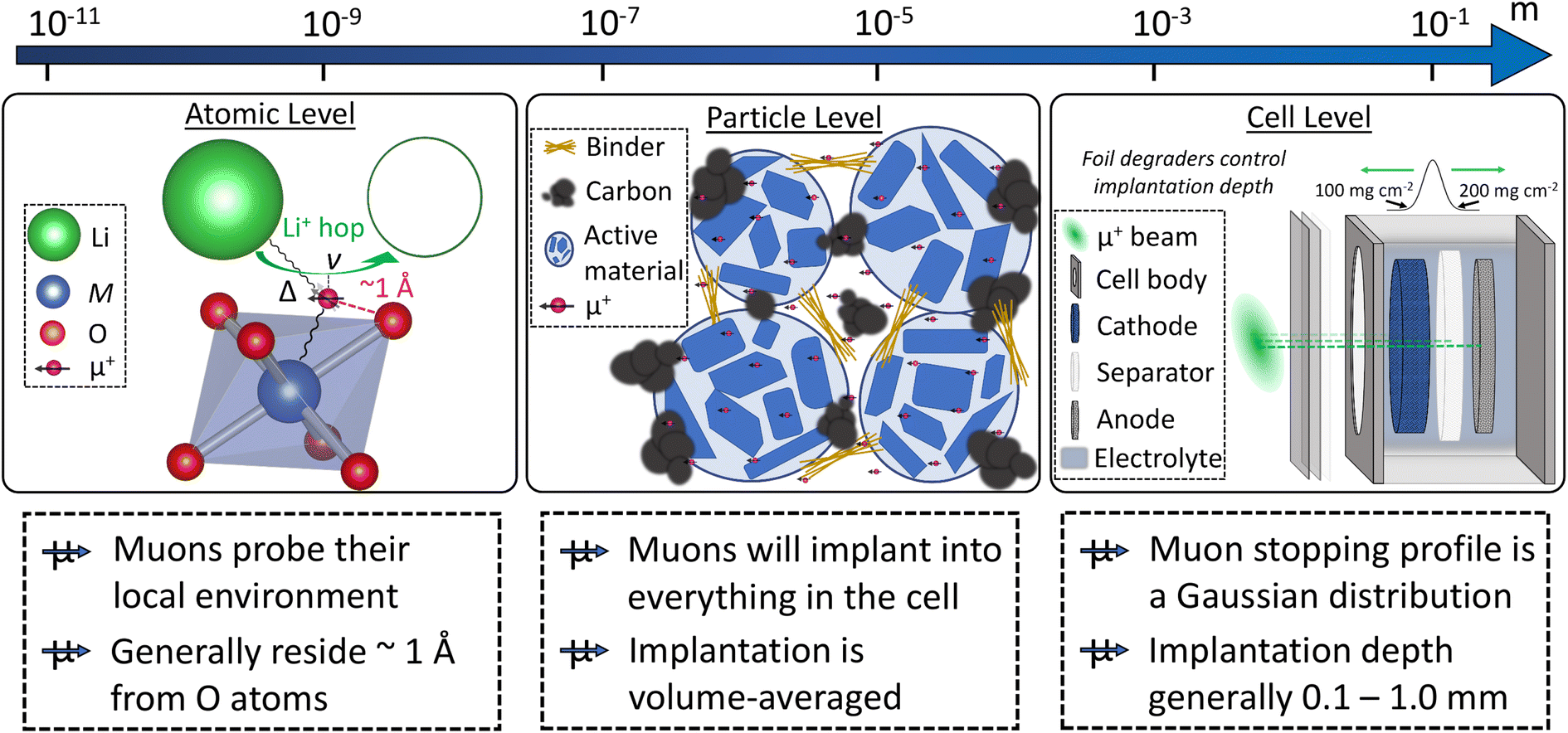 | ||
| Fig. 27 Depiction across length scales of how muons would be used to study an example of a functioning Li-ion battery, such as for an operando experiment. At the atomic level, muons generally bond with an oxygen atom; their spin is sensitive to their local environment, including nearby ions with a magnetic moment and dynamic hopping processes. Valuable information such as the field fluctuation rate (ν) and the static field distribution width (Δ) can be determined. At the particle level, muon implantation is volume-averaged across all components in the battery, which may include carbon, binder, and electrolyte. Given ionic diffusion in such materials is likely too fast (i.e. within the electrolyte) or too slow (i.e. within the binder) to be detected by the muon lifetime, any relaxing component of the total signal may be assigned to diffusion processes from within the active material. At the cell level, the muon implantation range (i.e. 100–200 mg cm−2 on EMU, ISIS) can be controlled to probe any region of the battery given it has sufficient thickness. | ||
4.1 Muon spectroscopy experiments
Muon spectroscopy experiments of battery materials generally probe ionic diffusion, for which there are many examples, especially involving Li+.130,131 Recent work which has broadened the horizons of μSR beyond more traditional battery technologies includes a recent study by Matsubara et al.,128 who became the first to investigate K+ dynamics using μSR, the study of which is challenging using standard techniques.132 Data was collected for honeycomb layered oxide material K2Ni2TeO6 between 50–550 K on the EMU beamline at ISIS Neutron and Muon Source using applied field strengths of 0, 10, and 30 G at each temperature. Two exponentially relaxing dynamic Kubo–Toyabe functions were fitted to the data, suggesting two distinct muon sites in the lattice, agreeing with low temperature zero-field measurements. The more common muon environment, AKT1, displays little change in the signal relaxation rate (λ), or the field fluctuation rate (ν), indicating a quasi-static environment with little variation in dynamics over the measured temperature range. ν can be directly related to the ionic hopping rate for most materials.133The second muon site, however, displays a rapid increase in ν above 250 K which signals the onset of diffusion above this temperature. The possibility of this trend originating from μ+ diffusion can be excluded via the corroboration of electrochemical measurements which also indicate K+ ion mobility above 250 K. The K+ diffusion coefficient, DK, was determined as around 1.9 × 10⁻¹¹ cm2 s−1 at 300 K, around an order of magnitude lower than that of Li+ motion in LiCoO2133 and around half that of Na+ motion in Na0.7CoO2.126 A low activation energy of 120 meV also highlighted the fast ion transport near the second muon site. In this instance, an accurate prediction of the muon site would prove beneficial for a greater understanding of diffusion pathways and to distinguish between the two experimentally determined muon environments.
Ferdani et al. also recently expanded the frontier of ionic diffusion experiments using μSR by tracking iodide ion transport in a perovskite solar cell material MAPbI3.129 Their study used complementary information gathered by ab initio modelling, impedance spectroscopy, and μSR to show that iodide ion motion is suppressed by the addition of cation dopants. Furthermore, Umegaki et al. used negatively charged muons to observe Li metal deposition on an overcharged graphite anode, with the potential to detect Li dendrite propagation.134 These works demonstrate the suitability of muons to observe ionic dynamics in future battery technologies and other research avenues, such as solar and fuel cells, as well as diagnose potential failure mechanisms in existing systems.
Electrochemical measurements, such as cyclic voltammetry, may also be used to determine Li diffusion rates in solid materials. Such techniques can evaluate the chemical diffusion coefficient, ![[D with combining tilde]](https://www.rsc.org/images/entities/i_char_0044_0303.gif) Li, which is related to DLi by a thermodynamic factor Θ. Although an important parameter governing the kinetic limitations of charging rates in batteries, the determination of Li is difficult due to an uncertainty in accuracy of the reactive surface area of a porous electrode in a liquid electrolyte. Sugiyama et al. have previously shown how μSR can be combined with electrochemical methods to predict the reactive surface area and cross-examine the diffusion coefficient. Their study observed the dependence of diffusion kinetics on lithium content in a common battery material LixCo1/3Ni1/3Mn1/3O2 (NMC111).135
Li, which is related to DLi by a thermodynamic factor Θ. Although an important parameter governing the kinetic limitations of charging rates in batteries, the determination of Li is difficult due to an uncertainty in accuracy of the reactive surface area of a porous electrode in a liquid electrolyte. Sugiyama et al. have previously shown how μSR can be combined with electrochemical methods to predict the reactive surface area and cross-examine the diffusion coefficient. Their study observed the dependence of diffusion kinetics on lithium content in a common battery material LixCo1/3Ni1/3Mn1/3O2 (NMC111).135
Various graphite/NMC111 cells were prepared and cycled to different potentials to obtain ex situ samples, which were extracted and transferred to μSR sample holders. The diffusion coefficient DLi was found to be lowest when the Li sites are fully occupied (x = 1), before increasing noticeably to reach a maximum at lower lithium contents (x ≈ 0.8), and finally falling slightly at a higher state of delithiation (x = 0.49). To reliably discuss these results, an interpretation of the possible muon sites is beneficial. As such, Fig. 28a displays how the electrostatic potential across the ab plane will change with Li content. This potential can be calculated at each site by using dipolar field calculations, and when compared to the experimentally determinable static field distribution width (Δ), can provide excellent validation for any predicted muon stopping sites. Additionally, Δ provides information on the nuclear magnetic environment of the muon, which can be linked to various phenomena such as bond length changes or phase transitions, particularly if the relevant structural information is known.
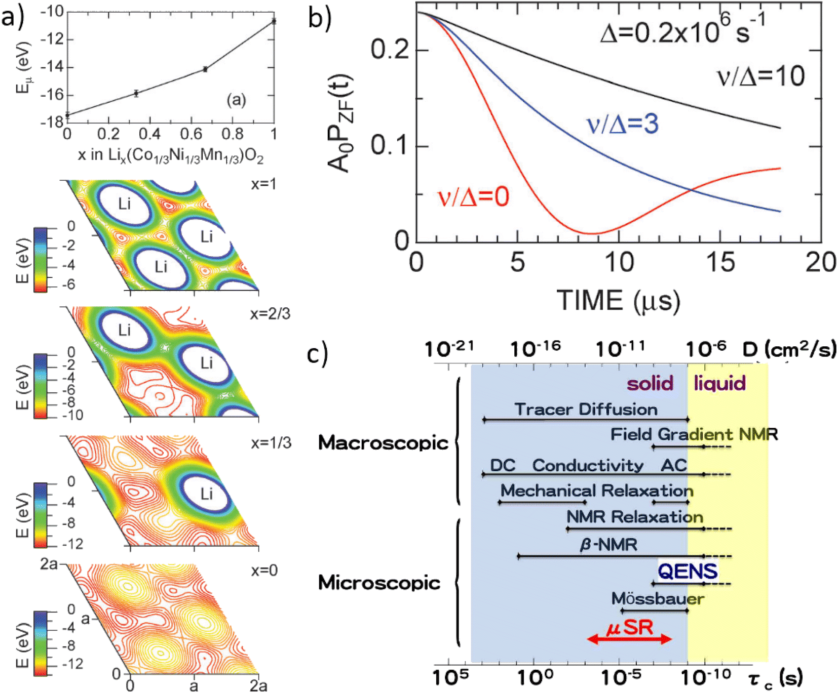 | ||
| Fig. 28 (a) The trend in electrostatic potential (Eμ) at the muon sites (Em) for the Li content in common cathode material Lix(Co1/3Ni1/3Mn1/3)O2, and its distribution (E) in the (a,b,0) plane. The reduction in electrostatic potential is clear as the cathode is delithiated (i.e. during charging). (b) Examples of a typical asymmetry spectrum from a μSR experiment. At low values of ν the trend resembles a static Kubo-Toyabe function and ionic dynamics are low, while at high values of ν the asymmetry takes an exponential form with time. © IOP Publishing. Reproduced with permission. All rights reserved. (c) The time range of μSR alongside the typical ranges of the diffusion coefficient (D) and motional correlation time (τc) of various techniques to measure ionic diffusion in liquids and solids. Reproduced from ref. 126 with permission from the PCCP Owner Societies. | ||
To link electrochemistry with μSR, Sugiyama et al. estimated the upper and lower boundary of the reactive surface area of an NMC111 electrode in a liquid electrolyte as between the geometrical area and the Brunauer–Emmet–Teller area from nitrogen adsorption. DLi, which was determined electrochemically for the maximum and minimum surface area, spanned around four orders of magnitude, roughly between 10−13 to 10−9 cm2 s−1, while DLi estimated via μSR was around 10−11 cm2 s−1 at an intermediate stage of delithiation. By comparison of both μSR and electrochemical methods, the reactive surface area can be narrowed down further, highlighting the strength of comparing multiple data sets from separate techniques. Furthermore, the diffusivity of ionic species as a function of lithium content, as opposed to in a pristine state, offers an improved quality of information which can be well correlated with points of change in the electrochemistry. As a consequence one can determine kinetic limitations or structural changes as a function of delithiation state, vital to fully characterise areas of material weakness and failure.
Further to bulk measurements of ionic diffusion using surface muons, it is also possible to use low energy muon (LEM) techniques to investigate materials using a narrower implantation depth profile.136 While conventional surface muon beams123 (energy ∼4 MeV) possess an energy spread of ∼10%, low energy muons can be controlled more precisely to within an energy range of 0 to 30 keV. This can allow controlled implantation of muons into the surface or near surface layers of materials at a depth resolution on a nanometer scale. These LEM techniques have excellent potential to be applied towards thin films,137 surface layers, or interfacial layers, all of which are vitally important for energy materials. Since the accurate determination of ion diffusion with μSR requires an adequate characterisation of the sample's composition and architecture, neutron reflectometry's capability to provide insights into the structure of nanometer thick features makes it highly complementary to LEM methods.
To date, there is only one LEM beam available for routine experiments, at the continuous muon source at the Paul Scherrer Institute (PSI) in Switzerland. The production of pulsed beams of LEMs has been demonstrated at the RIKEN-RAL facility at ISIS and developments are continuing at J-PARC with the aim of delivering higher muon fluxes than presently available. While LEM beams already offer excellent control of the muon implantation depth, the low efficiency of slowing down the muons from MeV to keV limits the counting statistics available in realistic measurement times. Developments of the production target and beamline at PSI, and also those at J-PARC, will hopefully increase the available fluxes to the level needed to study a wider range of energy materials. LEM beams could then be employed as a powerful tool to characterise specific aspects of battery design such as protective cathode coating layers, thin film batteries, or solid electrolyte interphases. Careful collaboration with bulk-sensitive techniques may also allow LEM experiments to elucidate the rate limiting layers/regions for ionic transport across a range of battery chemistries.
It is well understood how interfacial and surface layers can act as a bottleneck for ionic diffusion across many battery chemistries,138,139 although direct characterisation of these areas can be experimentally challenging due to their short length scale and often buried nature. Sugiyama et al.137 previously employed a low energy muon technique at PSI to study the Li+ diffusion behaviour in an isotropic thin film (thickness of 190 nm) of the low voltage spinel compound Li4Ti5O12 deposited on a substrate using pulsed laser deposition. These results were combined with powder measurements of the same compound using a surface muon beam at ISIS to compare how the form of the material influences the ionic diffusivity. Interestingly, Li+ diffusion in the Li4Ti5O12 thin film is faster (∼3.2(8) × 10−11 cm2 s−1) than in the powder sample (∼2.3(1) × 10−11 cm2 s−1). This is primarily ascribed to the single crystalline nature of the thin film: the absence of grain boundaries, which are generally of higher resistances than the inner grains, can afford a faster overall diffusion rate in the sample.
The next development towards the measurement of diffusion properties in realistic environments, such as functioning electrochemical cells, can be provided by in situ or operando measurements.140 In this case, in situ is defined as the measurement of an active material within a working cell but under no applied electric field gradient (i.e. cycling is paused), while operando is defined as the collection of μSR measurements while a cell is subject to an applied electric field (i.e. cycling). The first example of such an in situ μSR experiment was provided by McClelland et al.,141 who studied the first discharge of a NASICON-structured all-solid-state battery. A solid electrolyte LiZr2PO4 (LZP) was co-sintered with a similarly structured LiTi2PO4 (LTP) composite cathode and assembled within a CR2016 MTI coin cell possessing a 10 mm diameter Kapton inspection window. The muon stopping profile was controlled using silver foil degraders to ensure that data was collected from inside the solid electrolyte LZP, which was predicted to show little change in diffusional or structural properties over cycling. Instead, the field fluctuation rate is found to drop significantly below 1.2 V, indicating a drop in Li+ conductivity through the cell at low potential. Concurrently, a gradual decline in the field distribution width over discharge suggests a structural change, which may cause the narrowing of diffusion channels. This affect is also more pronounced below 1.2 V, reflecting the lower potential limit below which this system should not be cycled.
Alongside μSR measurements, EIS data were also collected, which inform on a gradual resistance increase over discharge likely reflecting how the instability between LZP and the Li anode influences the overall cell resistance. The information on interfacial and grain boundary resistances over cycling from impedance is complemented well by the bulk-dominated information from μSR. Both data sets can be correlated to provide an overall picture of which regions physically limit charge transfer and how this changes during cycling. Such methods can be applied across various cell configurations, including both solid and liquid electrolyte based. Future improvements in data collection and quality from the experiment reported by McClelland et al. are likely, by using, for example, a larger inspection window in a custom-made cell, and leave the opportunity open for a much higher detail study. Furthermore, the possibility of using lower momentum muons, which have less range straddle during implantation, allows a more precise depth penetration and may be used to study much thinner electrodes in working cells. Indeed, operando μSR measurements are possible and can offer a great increase in the detail of information achievable. The possibility of operando experiments on liquid electrolyte based cell chemistries remains open, given the timescale of Li+ diffusion within a liquid electrolyte is outside the range which can be probed by the muon (see Fig. 28c). Therefore, muons stopped in the electrolyte will undergo little spin relaxation and the corresponding signal can be subtracted from that of the active material as background.
Recent studies by Ohishi et al.142 and McClelland et al.143 have displayed the value of operando measurements for the study of commercially relevant cathode materials. Ohishi et al. employed a custom electrochemical cell developed at J-PARC to follow the change in lithium diffusion rate in LiCoO2 (LCO) over the first cycle and a half. They found that the diffusion coefficient, DLi, increased from around 10−12 to 10−11 cm2 s−1 over the first charge, with the greatest rate of change at the beginning of charge when the material is rapidly delithiated. This effect appears to be largely reversible during discharge. Furthermore, offline GITT measurements using the same cell were demonstrated, allowing an estimation of the reactive surface area of the electrode by using the geometrical area the both of the self diffusion coefficient (DJLi, determined by μSR), and the chemical diffusion coefficient (DC,appLi, determined by GITT). Such efforts illustrate the potential of operando μSR to understand the evolution of this parameter in detail. However, the widely reported morphological evolution of cathode materials, especially at high voltage and even in the first cycle,144 makes the use of complementary and direct characterisation techniques such as krypton physisorption and microscopy methods high desirable to fully quantify the complex origins of changes in the reactive surface area during cycling. A firm understanding of the link between reactive surface area during cycling and diffusion rates can aid the design of crack-resistant or protected cathode materials to enable fast rate capabilities (Fig. 29).
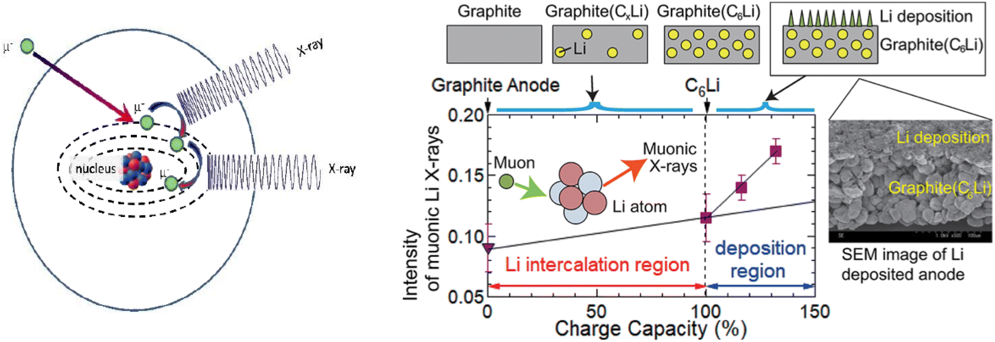 | ||
| Fig. 29 (Left) Schematic representation of the muon capture and travel through the electron shells of an atom. Reproduced with permission from ref. 145. Copyright © 2022, by the authors according to MDPI's open access policy. (Right) Intensity of muonic X-rays from metallic lithium growth in a graphite anode as a function of overcharge. Reproduced with permission from ref. 146. Copyright © 2020 American Chemical Society. | ||
It was mentioned before that negatively charged muons have not been used nearly as extensively as positively charged muons for materials characterisation. However, they have the potential to address some unique challenges in battery research. Negatively charged muons can be captured by atoms forming muonic atoms. The captured muon then cascades down through the energy levels of the electron shell within 10−13 seconds producing muonic X-rays in this process. In some instances, the muon can fall down to the nucleus causing it to emit one or more neutrons and gamma rays. Analogous to X-ray fluorescence, the emitted radiation by the muon movement throughout the electron shells of the atom can be analysed to determine its identity. This technique is called muonic atom X-ray emission spectroscopy (μ-XES) and has two main advantages over its X-ray counterpart due to the intrinsic properties of the muon: it is non destructive, and the emitted signal is much more energetic making it possible to detect light elements such as lithium.147 So far, this technique has been mainly applied to cultural heritage studies due to the non-destructiveness of the technique,145 however, Umegaki et al. used μ-XES to detect metallic lithium deposited on a graphite anode.146 They found that the intensity of muonic X-rays from metallic lithium was about 50 times higher than that of lithium ions, which allowed them to clearly distinguish between both. Furthermore, by measuring anodes overcharged at different levels they were able able to see a clear lithium dendrite growth as a function of overcharge evidenced by the increased intensity of the muonic X-ray signal coming from metallic lithium. It was also pointed out that μ-XES is suitable for quantitative and distribution analyses.
5 Conclusions
The above sections describe the principal features of neutron and muon techniques, with examples of their applications to probe the structure and dynamics of battery systems using both ex situ and in situ methods. In the case of neutrons, the intrinsic properties of the neutron provide important advantages for these types of experiments, with its ability to penetrate significant distances through most materials key to performing neutron experiments within, for example, electrochemical cells during charge–discharge cycling. Equally important is the increased sensitivity of the neutron probe (compared to the equivalent X-ray methods) to the location and behaviour of mobile light elements such as lithium and sodium within battery materials, which generally contain heavier transition metal species. Whilst it is outside the scope of this review, it is important to note that similar comments apply in other areas of ‘energy materials’, with examples including characterising the diffusion of oxide ions within electrode and electrolyte ceramics used within Solid Oxide Fuel Cells (SOFCs) and identifying new solid media to safely store hydrogen for potential use in future fuel cell powered vehicles.The research studies outlined in the sections above illustrate the advantages of in situ studies over ex situ ones, providing detailed characterisation of battery materials under conditions which mimic, as closely as possible, those found in commercial cells. Indeed, there is currently considerable activity devoted to the development of new in situ cells to probe both lithium and sodium based systems, especially devices for SANS, reflectometry and imaging methods. These will complement those for neutron diffraction and muon spectroscopy which are already in more widespread use. A key challenge for all these cell developments is to design a device which is optimised for both its neutron/muon performance (crudely, maximise the signal and minimise unwanted background), whilst maintaining an electrochemical performance which closely replicates that of a ‘real’ battery.
Despite the advantages mentioned above, the flux of neutrons available at current sources requires larger quantities of material to be included in the in situ cell than found in a typical commercial battery and/or limits studies under charge/discharge conditions to rather low rates. The development of new neutron sources with higher fluxes will clearly be beneficial to address this drawback. Indeed, the European Spallation Source (ESS), currently under construction in Lund, Sweden and due to be in full operation in late 2027, has already identified in situ studies of materials for energy production/storage as a high priority within its broad science programme. Similarly, a second target station will be constructed at the SNS in the USA, offering significant increases in the flux of neutrons at long wavelengths which are essential in areas such as SANS and NR. In the longer term, discussions have started within the UK for the construction of an ‘ISIS-II’ facility to complement the ESS and begin operations sometime in the 2030s. Nevertheless, it is important to note that many of the existing neutron facilities, and especially reactor-based ones, and are scheduled for closure within the next decade or so. To retain sufficient capacity to meet the needs of the research community it is also important to ensure that existing accelerator-based sources remain operational. As an example, the Target, Reflector and Moderator (TRAM) of the original target station at ISIS is currently (2022) being replaced after around 35 years of operation. In addition to providing some modest increases to the neutronic performance, this will ensure its continued operation for many years into the future.
An equally key requirement to successfully perform neutron and muon experiments is, of course, a suite of modern instruments covering techniques such as diffraction, imaging, reflectometry and spectroscopy. In most cases, these are designed to perform experiments across a broad range of science areas, but the current focus on ‘net-zero’ has inevitably led to a significant increase in the proportion of beamtime allocated to energy-related research. This, in turn, provides clear motivation to improve the performance of existing instruments (by, for example, upgrades to detectors or neutron optics) and to construct new instruments. The Endeavour programme at ISIS is an example of this, with funding currently being sought for a programme of 9 instrument builds/upgrades over a timeframe of around 10 years. Within the specific field of battery materials, individual projects that will have a major impact include HRPD-X, a major upgrade to the existing HRPD instrument which will allow time-resolved studies of electrochemical processes in situ at world-leading resolution, and Super-MuSR, which will increase the current level of performance by more than 10× through new detector and data acquisition technologies.
As discussed throughout this review, the materials typically used within battery applications are far from ‘perfect’ crystals. Many are multiphase and/or multicomponent, show relatively poor crystallinity, contain significant levels of local lattice disorder and display inhomogeneous stress distributions. Added to this is the complexity of performing studies in situ, where parasitic scattering from the cell can be problematic. As a consequence, providing a detailed description of the structure and dynamics of battery systems using in situ neutron and muon methods is a significant challenge which requires the development of advanced data correction and analysis techniques alongside the instrument and source facilities mentioned above. An example is the use of total scattering methods (Section 3.2) which can provide unique information concerning the short-range correlations between ions in a material. Whilst this approach is well established for ‘standard’ neutron experiments, probing the behaviour of (say) an electrode material of interest within an in situ cell requires detailed correction for the effects of attenuation of the beam as it passes through the cell and the scattering produced by the cell components, liquid electrolyte, etc. Development of an in situ cell for neutron total scattering is a worthwhile challenge.
Muons implanted within materials are now well-established as a probe of ionic motion, as long as the ion in question has a nuclear magnetic moment. This capability is often complementary with NMR measurements, but benefits from easily distinguished electronic and nuclear magnetic signals, which makes studying paramagnetic cathode materials routine. Instruments now under development, such as the forementioned Super-MuSR at ISIS, and developments for ultra-slow muons at J-PARC are expected to increase typical counting rates by one or more orders-of-magnitude. This will be particularly beneficial for in operando measurements where behaviour changing in various phases through cycling will be easier to resolve and faster cycling rates accessed to improve throughput. Investigating more challenging ions with smaller or less abundant magnetic moments and more distinct phases of ex situ materials will also be easier. The developments in counting rate expected in LEM beams in coming years will allow muons to study thin film batteries or analogues of interface layers that are otherwise challenging to investigate spectroscopically.
This review has discussed the many advantages of neutrons and muons as probes, but it cannot be stressed enough that these probes are extremely complementary and in most cases are best used in combination with other techniques. Indeed, the most challenging aspects of battery characterisation can only be addressed using a combination of probes and techniques. This includes the most difficult components to study such as the interfaces, as well as any operating system which is so complex due to the many chemical and physical reactions that take place over multiple length and time scales. Complementary techniques used simultaneously are the best way to capture multiple aspects of these systems, and as X-ray sources can be relatively small there are some examples of simultaneous neutron and X-ray capabilities; SAXS and SANS at D22 of ILL,148 neutron and X-ray Tomography (NeXT) system at the NIST thermal neutron imaging facility,149 and X-ray and neutron imaging on the NEUTRA (thermal neutrons) and ICON (cold neutrons) beamlines at SINQ, PSI.150 Meanwhile, the opportunity to combine operando data sets of neutron and muon experiments represents an exciting challenge; a detailed correlation between site occupancy diffusion characteristics can be used to well understand the fundamental structure–property relationships of materials during cycling. Applying simultaneous characterisation such as these to operating battery systems will contribute significantly to developing the next generation of batteries.
Author contributions
Emily Reynolds and Gabriel Pérez: conceptualization, investigation, writing – original draft, writing – review & editing, Project administration. Jake Brittain: investigation, writing – original draft, writing – review & editing. Innes McClelland: writing – original draft, writing – review & editing. Martin O. Jones: conceptualization, supervision, writing – review & editing, Funding acquisition. Helen Playford: supervision, writing – review & editing. Serena Cussen: supervision, funding acquisition. Peter Baker: supervision, funding acquisition, writing – review & editing. Stephen Hull: conceptualization, supervision, writing – original draft, writing – review & editing, funding acquisition.Conflicts of interest
There are no conflicts to declare.Acknowledgements
This work was supported by the Faraday Institution [grant numbers FIRG017 and FIRG018].Notes and references
- Angew. Chem., Int. Ed., 2019, 58, 16723 Search PubMed.
- A. Ghani Olabi, Q. Abbas, P. A. Shinde and M. Ali Abdelkareem, Energy, 2023, 266, 126408 CrossRef.
- Y. Chen, Y. Kang, Y. Zhao, L. Wang, J. Liu, Y. Li, Z. Liang, X. He, X. Li, N. Tavajohi and B. Li, J. Energy Chem., 2021, 59, 83–99 CrossRef CAS.
- N. Tapia-ruiz, A. R. Armstrong, H. Alptekin, M. A. Amores, H. Au, J. Barker, R. Boston, W. R. Brant, J. M. Brittain, Y. Chen, M. Chhowalla, Y.-s. Choi, S. I. R. Costa, M. C. Ribadeneyra, S. A. M. Dickson, E. I. Eweka, J. D. Forero-saboya, C. P. Grey, Z. Li, S. F. L. Mertens, R. Mogensen, L. Monconduit, D. M. C. Ould, R. G. Palgrave, P. Poizot, A. Ponrouch, S. Renault, E. M. Reynolds, A. Rudola, R. Sayers, D. O. Scanlon, S. Sen, V. R. Seymour, B. Silv, G. S. Stone, C. I. Thomas, M.-m. Titirici, J. Tong, T. J. Wood, D. S. Wright and R. Younesi, J. Phys. Energy, 2021, 3, 031503 CrossRef CAS.
- K. Mizushima, P. Jones, P. Wiseman and J. Goodenough, Mater. Res. Bull., 1980, 15, 783–789 CrossRef CAS.
- M. Thackeray, P. Johnson, L. de Picciotto, P. Bruce and J. Goodenough, Mater. Res. Bull., 1984, 19, 179–187 CrossRef CAS.
- C. Delmas, C. Fouassier and P. Hagenmuller, Physica, 1980, 99, 81–85 CAS.
- S. Komaba, N. Yabuuchi, T. Nakayama, A. Ogata, T. Ishikawa and I. Nakai, Inorg. Chem., 2012, 51, 6211–6220 CrossRef CAS PubMed.
- Z. Lu and J. R. Dahn, J. Electrochem. Soc., 2001, 148, A1225–A1229 CrossRef CAS.
- B. Wang, Y. Han, X. Wang, N. Bahlawane, H. Pan, M. Yan and Y. Jiang, iScience, 2018, 3, 110–133 CrossRef CAS PubMed.
- B. Zhang, K. Ma, X. Lv, K. Shi, Y. Wang, Z. Nian, Y. Li, L. Wang, L. Dai and Z. He, J. Alloys Compd., 2021, 867, 159060 CrossRef CAS.
- J. Barker, M. Y. Saidi and J. L. Swoyer, US Pat. 6387568, 2002.
- Y. Ahmad, M. Colin, C. Gervillie-Mouravieff, M. Dubois and K. Guérin, Synth. Met., 2021, 280, 116864 CrossRef CAS.
- D. A. Stevens and J. R. Dahn, J. Electrochem. Soc., 2000, 147, 1271 CrossRef CAS.
- D. A. Stevens and J. R. Dahn, J. Electrochem. Soc., 2001, 148, A803 CrossRef CAS.
- S. Dong, N. Lv, Y. Wu, Y. Zhang, G. Zhu and X. Dong, Nano Today, 2022, 42, 101349 CrossRef CAS.
- K. Xu, Chem. Rev., 2004, 104, 4303–4418 CrossRef CAS PubMed.
- H. Aziam, B. Larhrib, C. Hakim, N. Sabi, H. Ben Youcef and I. Saadoune, Renewable Sustainable Energy Rev., 2022, 167, 112694 CrossRef CAS.
- K. Xu, Chem. Rev., 2014, 114, 11503–11618 CrossRef CAS PubMed.
- A. C. Hannon, Encyclopedia of Spectroscopy and Spectrometry, ed. J. C. Lindon, G. E. Tranter and D. Koppenaal, Academic Press, London, 2016, vol. 3, p. 88 Search PubMed.
- D. S. Sivia, Elementary Scattering Theory: for X-Ray and Neutron Users, Oxford University Press, Oxford, 2011 Search PubMed.
- B. T. M. Willis and C. J. Carlile, Experimental Neutron Scattering, Oxford University Press, 2017 Search PubMed.
- M. Arai and K. Crawford, Neutron Imaging and Applications, Renewable Sustainable Energy Rev., 2009, 13–30 Search PubMed.
- C. Hammond, The Basics of Crystallography and Diffraction, Oxford University Press, Oxford, 2015 Search PubMed.
- V. Pecharsky and P. Zavalij, Fundamentals of Powder Diffraction and Structural Characterization of Materials, New York, 2005 Search PubMed.
- H. M. Rietveld, J. Appl. Crystallogr., 1969, 2, 65–71 CrossRef CAS.
- T. Takami, Y. Morita, M. Yonemura, Y. Ishikawa, S. Tanaka, M. Mori, T. Fukunaga and E. Matsubara, ACS Appl. Energy Mater., 2018, 1, 2546–2554 CrossRef CAS.
- Y. Deng, C. Eames, L. H. B. Nguyen, O. Pecher, K. J. Griffith, M. Courty, B. Fleutot, J.-N. Chotard, C. P. Grey, M. S. Islam and C. Masquelier, Chem. Mater., 2018, 30, 2618–2630 CrossRef CAS.
- C. Li, W. H. Kan, H. Xie, Y. Jiang, Z. Zhao, C. Zhu, Y. Xia, J. Zhang, K. Xu, D. Mu and F. Wu, Adv. Sci., 2019, 6, 1801406 CrossRef PubMed.
- J. W. Somerville, A. Sobkowiak, N. Tapia-Ruiz, J. Billaud, J. G. Lozano, R. A. House, L. C. Gallington, T. Ericsson, L. Häggström, M. R. Roberts, U. Maitra and P. G. Bruce, Energy Environ. Sci., 2019, 12, 2223–2232 RSC.
- Z.-Y. Li, H. Guo, X. Ma, K. Sun, D. Chen, L. He and S. Han, J. Phys. Chem. C, 2019, 123, 19298–19306 CrossRef CAS.
- P. Miao, R. Wang, W. Zhu, J. Liu, T. Liu, J. Hu, S. Li, Z. Tan, A. Koda, F. Zhu, E. Feng, Y. Su, T. Kamiyama, Y. Xiao and F. Pan, Appl. Phys. Lett., 2019, 114, 203901 CrossRef.
- H. Gao, Q. Yan, P. Xu, H. Liu, M. Li, P. Liu, J. Luo and Z. Chen, ACS Appl. Mater. Interfaces, 2020, 12, 51546–51554 CrossRef CAS PubMed.
- N. Sharma, D. Yu, Y. Zhu, Y. Wu and V. K. Peterson, Chem. Mater., 2013, 25, 754–760 CrossRef CAS.
- N. Sharma, D. H. Yu, Y. Zhu, Y. Wu and V. K. Peterson, J. Power Sources, 2017, 342, 562–569 CrossRef CAS.
- D. Goonetilleke, J. C. Pramudita, M. Hagan, O. K. Al Bahri, W. K. Pang, V. K. Peterson, J. Groot, H. Berg and N. Sharma, J. Power Sources, 2017, 343, 446–457 CrossRef CAS.
- W. K. Pang, V. K. Peterson, N. Sharma, J.-J. Shiu and S.-h. Wu, Chem. Mater., 2014, 26, 2318–2326 CrossRef CAS.
- J. C. Pérez-Flores, F. García-Alvarado, M. Hoelzel, I. Sobrados, J. Sanz and A. Kuhn, Dalton Trans., 2012, 41, 14633–14642 RSC.
- M. Medarde, M. Mena, J. L. Gavilano, E. Pomjakushina, J. Sugiyama, K. Kamazawa, V. Y. Pomjakushin, D. Sheptyakov, B. Batlogg, H. R. Ott, M. Månsson and F. Juranyi, Phys. Rev. Lett., 2013, 110, 266401 CrossRef CAS PubMed.
- Y. Wang, R. Xiao, Y.-S. Hu, M. Avdeev and L. Chen, Nat. Commun., 2015, 6, 6954 CrossRef CAS PubMed.
- H. L. B. Boström and W. R. Brant, J. Mater. Chem. C, 2022, 10, 13690–13699 RSC.
- I. Nielsen, D. Dzodan, D. O. Ojwang, P. F. Henry, A. Ulander, G. Ek, L. Häggström, T. Ericsson, H. L. B. Boström and W. R. Brant, J. Phys.: Energy, 2022, 4, 044012 Search PubMed.
- J. Zhang, Y. Liu, X. Zhao, L. He, H. Liu, Y. Song, S. Sun, Q. Li, X. Xing and J. Chen, Adv. Mater., 2020, 32, 1906348 CrossRef CAS PubMed.
- R. Muruganantham, Y.-T. Chiu, C.-C. Yang, C.-W. Wang and W.-R. Liu, Sci. Rep., 2017, 7, 14808 CrossRef PubMed.
- W. K. Pang, M. Alam, V. K. Peterson and N. Sharma, J. Mater. Res., 2015, 30, 373–380 CrossRef CAS.
- W. K. Pang, V. K. Peterson, N. Sharma, J.-J. Shiu and S.-h. Wu, Powder Diffr., 2014, 29, S59–S63 CrossRef CAS.
- N. Sharma and V. K. Peterson, J. Power Sources, 2013, 244, 695–701 CrossRef CAS.
- I. A. Bobrikov, N. Samoylova, S. V. Sumnikov, O. Ivanshina, R. N. Vasin, A. I. Beskrovnyi and A. M. Balagurov, J. Power Sources, 2017, 372, 74–81 CrossRef CAS.
- P.-H. Lee, S.-h. Wu, W. K. Pang and V. K. Peterson, J. Power Sources, 2018, 374, 31–39 CrossRef CAS.
- K. Richter, T. Waldmann, N. Paul, N. Jobst, R.-G. Scurtu, M. Hofmann, R. Gilles and M. Wohlfahrt-Mehrens, ChemSusChem, 2020, 13, 529–538 CrossRef CAS PubMed.
- C. von Lüders, V. Zinth, S. V. Erhard, P. J. Osswald, M. Hofmann, R. Gilles and A. Jossen, J. Power Sources, 2017, 342, 17–23 CrossRef.
- Ö. Bergstöm, A. M. Andersson, K. Edström and T. Gustafsson, J. Appl. Crystallogr., 1998, 31, 823–825 CrossRef.
- L. Vitoux, M. Reichardt, S. Sallard, P. Novák, D. Sheptyakov and C. Villevieille, Front. Energy Res., 2018, 6, 1–16 CrossRef.
- M. Bianchini, J. B. Leriche, J.-L. Laborier, L. Gendrin, E. Suard, L. Croguennec and C. Masquelier, J. Electrochem. Soc., 2013, 160, A2176–A2183 CrossRef CAS.
- V. A. Godbole, M. Heβ, C. Villevieille, H. Kaiser, J.-F. Colin and P. Novák, RSC Adv., 2013, 3, 757–763 RSC.
- W. K. Pang and V. K. Peterson, J. Appl. Crystallogr., 2015, 48, 280–290 CrossRef CAS.
- M. Roberts, J. J. Biendicho, S. Hull, P. Beran, T. Gustafsson, G. Svensson and K. Edström, J. Power Sources, 2013, 226, 249–255 CrossRef CAS.
- N. Sharma, G. Du, A. J. Studer, Z. Guo and V. K. Peterson, Solid State Ionics, 2011, 199–200, 37–43 CrossRef CAS.
- B. Dong, J. J. Biendicho, S. Hull, R. I. Smith and A. R. West, J. Electrochem. Soc., 2018, 165, A793–A801 CrossRef CAS.
- D. Sheptyakov, L. Boulet-Roblin, V. Pomjakushin, P. Borel, C. Tessier and C. Villevieille, J. Mater. Chem. A, 2020, 8, 1288–1297 RSC.
- M. Scavini, M. Coduri, M. Allieta, M. Brunelli and C. Ferrero, Chem. Mater., 2012, 24, 1338–1345 CrossRef CAS.
- D. Maurya, A. Kumar, V. Petkov, J. E. Mahaney, R. S. Katiyar and S. Priya, RSC Adv., 2014, 4, 1283–1292 RSC.
- C. H. Booth, F. Bridges, G. H. Kwei, J. M. Lawrence, A. L. Cornelius and J. J. Neumeier, Phys. Rev. Lett., 1998, 80, 853–856 CrossRef CAS.
- D. A. Keen, M. G. Tucker and M. T. Dove, J. Phys.: Condens. Matter, 2005, 17, S15–S22 CrossRef CAS.
- J. Wang, D. Zhou, X. He, L. Zhang, X. Cao, D. Ning, B. Yan, X. Qi, J. Li, V. Murzin, E. Paillard, X. Liu, G. Schumacher, M. Winter and J. Li, ACS Appl. Mater. Interfaces, 2020, 12, 5017–5024 CrossRef CAS PubMed.
- E. Zhao, M. Zhang, X. Wang, E. Hu, J. Liu, X. Yu, M. Olguin, T. A. Wynn, Y. S. Meng, K. Page, F. Wang, H. Li, X.-Q. Yang, X. Huang and L. Chen, Energy Storage Mater., 2020, 24, 384–393 CrossRef.
- N. Ishida, K. Kawagoe, N. Kitamura, J. Akimoto and Y. Idemoto, J. Solid State Electrochem., 2021, 25, 1319–1326 CrossRef CAS.
- J. Ma, S.-H. Bo, L. Wu, Y. Zhu, C. P. Grey and P. G. Khalifah, Chem. Mater., 2015, 27, 2387–2399 CrossRef CAS.
- M. Diaz-Lopez, M. Freire, Y. Joly, C. V. Colin, H. E. Fischer, N. Blanc, N. Boudet, V. Pralong and P. Bordet, Chem. Mater., 2018, 30, 3060–3070 CrossRef CAS.
- H. Ji, A. Urban, D. A. Kitchaev, D.-H. Kwon, N. Artrith, C. Ophus, W. Huang, Z. Cai, T. Shi, J. C. Kim, H. Kim and G. Ceder, Nat. Commun., 2019, 10, 592 CrossRef CAS PubMed.
- J. Liu, A. Huq, Z. Moorhead-Rosenberg, A. Manthiram and K. Page, Chem. Mater., 2016, 28, 6817–6821 CrossRef CAS.
- H. Alptekin, H. Au, A. C. S. Jensen, E. Olsson, M. Goktas, T. F. Headen, P. Adelhelm, Q. Cai, A. J. Drew and M.-M. Titirici, ACS Appl. Energy Mater., 2020, 3, 9918–9927 CrossRef CAS.
- C. Bommier, T. W. Surta, M. Dolgos and X. Ji, Nano Lett., 2015, 15, 5888–5892 CrossRef CAS PubMed.
- B. Liu, A. Abouimrane, Y. Ren, J. Neuefeind, Z. Z. Fang and K. Amine, J. Electrochem. Soc., 2013, 160, A882–A887 CrossRef CAS.
- X. Rong, J. Liu, E. Hu, Y. Liu, Y. Wang, J. Wu, X. Yu, K. Page, Y.-S. Hu, W. Yang, H. Li, X.-Q. Yang, L. Chen and X. Huang, Joule, 2018, 2, 125–140 CrossRef CAS.
- E. Zhao, Q. Li, F. Meng, J. Liu, J. Wang, L. He, Z. Jiang, Q. Zhang, X. Yu, L. Gu, W. Yang, H. Li, F. Wang and X. Huang, Angew. Chem., Int. Ed., 2019, 58, 4323–4327 CrossRef CAS PubMed.
- M. A. Jones, P. J. Reeves, I. D. Seymour, M. J. Cliffe, S. E. Dutton and C. P. Grey, Chem. Commun., 2019, 55, 9027–9030 RSC.
- R. Pynn, Los Alamos Sci., 1990, 19, 1–31 Search PubMed.
- S. Mamun, M. Herstedt, K. Oikawa, T. Gustafsson, T. Otomo, M. Furusaka, T. Kamiyama, H. Sakaebe and K. Edström, Appl. Phys. A, 2002, 74, s1028–s1030 CrossRef CAS.
- G. Sandí, P. Thiyagarajan, K. A. Carrado and R. E. Winans, Chem. Mater., 1999, 11, 235–240 CrossRef.
- T. K. Zakharchenko, M. V. Avdeev, A. V. Sergeev, A. V. Chertovich, O. I. Ivankov, V. I. Petrenko, Y. Shao-Horn, L. V. Yashina and D. M. Itkis, Nanoscale, 2019, 11, 6838–6845 RSC.
- S. K. Sinha, T. Freltoft and J. Kjems, in Kinetics of Aggregation and Gelation, ed. F. Family and D. P. Landau, Elsevier, Amsterdam 1984, p. 87 Search PubMed.
- J. Teixiera, in On Growth and Form: Fractal and Non-fractal Patterns in Physics, ed. H. E. Stanley and N. Ostrowsky, Springer Science, Dordretch, 2012, vol 100, p. 145 Search PubMed.
- P. Ferguson, M. Fleischauer, J. LaForge, A. Todd, P. Li and J. Dahn, J. Alloys Compd., 2012, 541, 168–172 CrossRef CAS.
- N. Paul, J. Brumbarov, A. Paul, Y. Chen, J.-F. Moulin, P. Mueller-Buschbaum, J. Kunze-Liebhaeuser and R. Gilles, J. Appl. Crystallogr., 2015, 48, 444–454 CrossRef CAS.
- C. J. Jafta, X.-G. Sun, G. M. Veith, G. V. Jensen, S. M. Mahurin, M. P. Paranthaman, S. Dai and C. A. Bridges, Energy Environ. Sci., 2019, 12, 1866–1877 RSC.
- C. A. Bridges, X.-G. Sun, J. Zhao, M. P. Paranthaman and S. Dai, J. Phys. Chem. C, 2012, 116, 7701–7711 CrossRef CAS.
- X. He, J. Wang, R. Wang, B. Qiu, H. Frielinghaus, P. Niehoff, H. Liu, M. C. Stan, E. Paillard, M. Winter and J. Li, J. Mater. Chem. A, 2016, 4, 7230–7237 RSC.
- S.-Y. Chung, S.-Y. Choi, T.-H. Kim and S. Lee, ACS Nano, 2015, 9, 850–859 CrossRef CAS PubMed.
- S. Risse, E. Härk, B. Kent and M. Ballauff, ACS Nano, 2019, 13, 10233–10241 CrossRef CAS PubMed.
- M. Hirayama, M. Yonemura, K. Suzuki, N. Torikai, H. Smith, E. Watkinsand, J. Majewski and R. Kanno, Electrochemistry, 2010, 78, 413–415 CrossRef CAS.
- J. F. Browning, L. Baggetto, K. L. Jungjohann, Y. Wang, W. E. Tenhaeff, J. K. Keum, D. L. Wood and G. M. Veith, ACS Appl. Mater. Interfaces, 2014, 6, 18569–18576 CrossRef CAS PubMed.
- B. Jerliu, L. Dörrer, E. Hüger, G. Borchardt, R. Steitz, U. Geckle, V. Oberst, M. Bruns, O. Schneider and H. Schmidt, Phys. Chem. Chem. Phys., 2013, 15, 7777–7784 RSC.
- T. Minato, H. Kawaura, M. Hirayama, S. Taminato, K. Suzuki, N. L. Yamada, H. Sugaya, K. Yamamoto, K. Nakanishi, Y. Orikasa, H. Tanida, R. Kanno, H. Arai, Y. Uchimoto and Z. Ogumi, J. Phys. Chem. C, 2016, 120, 20082–20088 CrossRef CAS.
- B.-K. Seidlhofer, B. Jerliu, M. Trapp, E. Hüger, S. Risse, R. Cubitt, H. Schmidt, R. Steitz and M. Ballauff, ACS Nano, 2016, 10, 7458–7466 CrossRef CAS PubMed.
- A. Ronneburg, M. Trapp, R. Cubitt, L. Silvi, S. Cap, M. Ballauff and S. Risse, Energy Storage Mater., 2019, 18, 182–189 CrossRef.
- S.-I. Lee, M. Schömer, H. Peng, K. A. Page, D. Wilms, H. Frey, C. L. Soles and D. Y. Yoon, Chem. Mater., 2011, 23, 2685–2688 CrossRef CAS.
- Q. Chen, N. H. Jalarvo and W. Lai, J. Mater. Chem. A, 2020, 8, 25290–25297 RSC.
- M. K. Gupta, S. K. Mishra, R. Mittal, B. Singh, P. Goel, S. Mukhopadhyay, R. Shukla, S. N. Achary, A. K. Tyagi and S. L. Chaplot, Phys. Rev. Mater., 2020, 4, 45802 CrossRef CAS.
- C.-W. Hu, C.-H. Lee and P.-J. Wu, J. Chin. Chem. Soc., 2021, 68, 507–511 CrossRef CAS.
- T. J. Willis, D. G. Porter, D. J. Voneshen, S. Uthayakumar, F. Demmel, M. J. Gutmann, M. Roger, K. Refson and J. P. Goff, Sci. Rep., 2018, 8, 3210 CrossRef CAS PubMed.
- J. Lefevr, L. Cervini, J. M. Griffin and D. Blanchard, J. Phys. Chem. C, 2018, 122, 15264–15275 CrossRef CAS.
- K. I. S. Mongcopa, D. A. Gribble, W. S. Loo, M. Tyagi, S. A. Mullin and N. P. Balsara, Macromolecules, 2020, 53, 2406–2411 CrossRef CAS.
- P. Benedek, N. Yazdani, H. Chen, N. Wenzler, F. Juranyi, M. Månsson, M. S. Islam and V. C. Wood, Sustainable Energy Fuels, 2019, 3, 508–513 RSC.
- R. L. Sacci, J. L. Bañuelos, G. M. Veith, K. C. Littrell, Y. Q. Cheng, C. U. Wildgruber, L. L. Jones, A. J. Ramirez-Cuesta, G. Rother and N. J. Dudney, J. Phys. Chem. C, 2015, 119, 9816–9823 CrossRef CAS.
- M. H. Braga, J. A. Ferreira, V. Stockhausen, J. E. Oliveira and A. El-Azab, J. Mater. Chem. A, 2014, 2, 5470–5480 RSC.
- J. S. G. Myrdal, D. Blanchard, D. Sveinbjörnsson and T. Vegge, J. Phys. Chem. C, 2013, 117, 9084–9091 CrossRef CAS.
- J. Wind, R. A. Mole, D. Yu and C. D. Ling, Chem. Mater., 2017, 29, 7408–7415 CrossRef CAS.
- M. A. Hamilton, A. C. Barnes, W. S. Howells and H. E. Fischer, J. Phys.: Condens. Matter, 2001, 13, 2425–2436 CrossRef CAS.
- M.-L. Saboungi, D. L. Price, G. Mao, R. Fernandez-Perea, O. Borodin, G. D. Smith, M. Armand and W. Howells, Solid State Ionics, 2002, 147, 225–236 CrossRef CAS.
- M. Heere, A.-L. Hansen, S. Payandeh, N. Aslan, G. Gizer, M. H. Sørby, B. C. Hauback, C. Pistidda, M. Dornheim and W. Lohstroh, Sci. Rep., 2020, 10, 9080 CrossRef CAS PubMed.
- I. Popov, R. L. Sacci, N. C. Sanders, R. A. Matsumoto, M. W. Thompson, N. C. Osti, T. Kobayashi, M. Tyagi, E. Mamontov, M. Pruski, P. T. Cummings and A. P. Sokolov, J. Phys. Chem. C, 2020, 124, 8457–8466 CrossRef CAS.
- M. A. González, O. Borodin, M. Kofu, K. Shibata, T. Yamada, O. Yamamuro, K. Xu, D. L. Price and M.-L. Saboungi, J. Phys. Chem. Lett., 2020, 11, 7279–7284 CrossRef PubMed.
- H. Z. Bilheux, R. McGreevy and I. S. Anderson, Neutron Imaging and Applications, Springer, 2009 Search PubMed.
- P. Vontobel, E. H. Lehmann, R. Hassanein and G. Frei, Physica B, 2006, 385–386, 475–480 CrossRef CAS.
- W. Kockelmann, G. Frei, E. Lehmann, P. Vontobel and J. Santisteban, Nucl. Instrum. Methods Phys. Res., Sect. A, 2007, 578, 421–434 CrossRef CAS.
- J. P. Owejan, J. J. Gagliardo, S. J. Harris, H. Wang, D. S. Hussey and D. L. Jacobson, Electrochim. Acta, 2012, 66, 94–99 CrossRef CAS.
- R. F. Ziesche, T. Arlt, D. P. Finegan, T. M. M. Heenan, A. Tengattini, D. Baum, N. Kardjilov, H. Markötter, I. Manke, W. Kockelmann, D. J. L. Brett and P. R. Shearing, Nat. Commun., 2020, 11, 777 CrossRef CAS PubMed.
- K. Kino, M. Yonemura, Y. Ishikawa and T. Kamiyama, Solid State Ionics, 2016, 288, 257–261 CrossRef CAS.
- R. F. Ziesche, A. S. Tremsin, C. Huang, C. Tan, P. S. Grant, M. Storm, D. J. L. Brett, P. R. Shearing and W. Kockelmann, J. Imaging, 2020, 6, 1–16 CrossRef PubMed.
- B. Michalak, H. Sommer, D. Mannes, A. Kaestner, T. Brezesinski and J. Janek, Sci. Rep., 2015, 5, 15627 CrossRef CAS PubMed.
- A. Senyshyn, V. Baran, M. J. Mühlbauer, M. Etter, M. Schulz, K. Tu and Y. Yang, ACS Appl. Energy Mater., 2021, 4, 3110–3117 CrossRef CAS.
- S. J. Blundell, Contemp. Phys., 1999, 40, 175–192 CrossRef CAS.
- I. McClelland, B. Johnston, P. J. Baker, M. Amores, E. J. Cussen and S. A. Corr, Annu. Rev. Mater. Res., 2020, 50, 1–15 CrossRef.
- P. Benedek, O. K. Forslund, E. Nocerino, N. Yazdani, N. Matsubara, Y. Sassa, F. Jurányi, M. Medarde, M. Telling, M. Månsson and V. Wood, ACS Appl. Mater. Interfaces, 2020, 12, 16243–16249 CrossRef CAS PubMed.
- M. Månsson and J. Sugiyama, Phys. Scr., 2013, 88, 068509 CrossRef.
- R. D. Bayliss, B. Key, G. S. Gautam, P. Canepa, B. J. Kwon, S. H. Lapidus, F. Dogan, A. A. Adil, A. S. Lipton, P. J. Baker, G. Ceder, J. T. Vaughey and J. Cabana, Chem. Mater., 2020, 32, 663–670 CrossRef CAS.
- N. Matsubara, E. Nocerino, O. K. Forslund, A. Zubayer, P. Gratrex, D. Andreica, J. Sugiyama, Z. Guguchia, S. Cottrell, A. Kalaboukhov, Y. Sassa, T. Masese and M. Månsson, Sci. Rep., 2020, 10, 18305 CrossRef CAS PubMed.
- D. W. Ferdani, S. R. Pering, D. Ghosh, P. Kubiak, A. B. Walker, S. E. Lewis, A. L. Johnson, P. J. Baker, M. S. Islam and P. J. Cameron, Energy Environ. Sci., 2019, 12, 2264–2272 RSC.
- M. Amores, T. E. Ashton, P. J. Baker, E. J. Cussen and S. A. Corr, J. Mater. Chem. A, 2016, 4, 1729–1736 RSC.
- A. S. Powell, J. S. Lord, D. H. Gregory and J. J. Titman, J. Phys. Chem. C, 2009, 113, 20758–20763 CrossRef CAS.
- H. Alloul, I. R. Mukhamedshin, A. V. Dooglav, Y. V. Dmitriev, C. C. Ciomaga, L. Pinsard-Gaudart and G. Collin, Phys. Rev. B, 2012, 85, 134433 CrossRef.
- J. Sugiyama, K. Mukai, Y. Ikedo, H. Nozaki, M. Månsson and I. Watanabe, Phys. Rev. Lett., 2009, 103, 147601 CrossRef PubMed.
- I. Umegaki, Y. Higuchi, Y. Kondo, K. Ninomiya, S. Takeshita, M. Tampo, H. Nakano, H. Oka, J. Sugiyama, M. K. Kubo and Y. Miyake, Anal. Chem., 2020, 92, 8194–8200 CrossRef CAS PubMed.
- J. Sugiyama, K. Mukai, M. Harada, H. Nozaki, K. Miwa, T. Shiotsuki, Y. Shindo, S. R. Giblin and J. S. Lord, Phys. Chem. Chem. Phys., 2013, 15, 10402 RSC.
- E. Morenzoni, Appl. Magn. Reson., 1997, 13, 219–229 CrossRef CAS.
- J. Sugiyama, H. Nozaki, I. Umegaki, K. Mukai, K. Miwa, S. Shiraki, T. Hitosugi, A. Suter, T. Prokscha, Z. Salman, J. S. Lord and M. Månsson, Phys. Rev. B, 2015, 92, 014417 CrossRef.
- B. Wu, C. Chen, D. L. Danilov, M. Jiang, L. H. J. Rajimakers, R.-A. Eichel and P. L. Notten, ACS Omega, 2022, 7, 32740–32748 CrossRef CAS PubMed.
- A. Banerjee, X. Wang, C. Fang, E. A. Wu and Y. S. Meng, Chem. Rev., 2020, 120, 6878–6933 CrossRef CAS PubMed.
- P. P. R. M. L. Harks, F. M. Mulder and P. H. L. Notten, J. Power Sources, 2015, 288, 92–105 CrossRef CAS.
- I. McClelland, S. G. Booth, H. El-Shinawi, B. I. J. Johnston, J. Clough, W. Guo, E. J. Cussen, P. J. Baker and S. A. Corr, ACS Appl. Energy Mater., 2021, 4, 1527–1536 CrossRef CAS PubMed.
- D. I. K. Ohishi, R. Tatara, I. Umegaki, A. Koda, S. Komaba and J. Sugiyama, ACS Appl. Energy Mater., 2022, 5, 12538–12544 CrossRef.
- I. McClelland, S. G. Booth, N. N. Anthonisamy, L. Middlemiss, G. E. Pérez, E. J. Cussen, P. J. Baker and S. A. Cussen, ChemRxiv, 2022 Search PubMed , preprint.
- E. Trevisanello, R. Ruess, G. Conforto, F. H. Richter and J. Janek, Adv. Energy Mater., 2021, 23, 2003400 CrossRef.
- M. Cataldo, M. Clemenza, K. Ishida and A. D. Hillier, Appl. Sci., 2022, 12, 4237 CrossRef CAS.
- I. Umegaki, Y. Higuchi, Y. Kondo, K. Ninomiya, S. Takeshita, M. Tampo, H. Nakano, H. Oka, J. Sugiyama and M. K. Kubo, et al. , Anal. Chem., 2020, 92, 8194–8200 CrossRef CAS PubMed.
- A. Hillier, D. M. Paul and K. Ishida, Microchem. J., 2016, 125, 203–207 CrossRef CAS.
- E. Metwalli, K. Götz, T. Zech, C. BÃr, I. Schuldes, A. Martel, L. Porcar and T. Unruh, Appl. Sci., 2021, 11, 1–11 Search PubMed.
- J. M. LaManna, D. S. Hussey, E. Baltic and D. L. Jacobson, Rev. Sci. Instrum., 2017, 88, 113702 CrossRef CAS PubMed.
- A. Kaestner, J. Hovind, P. Boillat, C. Muehlebach, C. Carminati, M. Zarebanadkouki and E. Lehmann, Phys. Procedia, 2017, 88, 314–321 CrossRef CAS.
| This journal is © The Royal Society of Chemistry 2023 |