Origin and regulation of triaxial magnetic anisotropy in the ferromagnetic semiconductor CrSBr monolayer†
Bing
Wang
,
Yaxuan
Wu
 ,
Yihang
Bai
,
Puyuan
Shi
,
Guangbiao
Zhang
*,
Yungeng
Zhang
* and
Chang
Liu
,
Yihang
Bai
,
Puyuan
Shi
,
Guangbiao
Zhang
*,
Yungeng
Zhang
* and
Chang
Liu
 *
*
Joint Center for Theoretical Physics, School of Physics and Electronics, Henan University, Kaifeng 475004, People's Republic of China. E-mail: gbzhang@vip.henu.edu.cn; 20130016@vip.henu.edu.cn; cliu@vip.henu.edu.cn
First published on 20th July 2023
Abstract
Magnetic anisotropy plays a vital role in stabilizing the long-range magnetic order of two-dimensional ferromagnetic systems. In this work, using the first-principles method, we systematically explored the triaxial magnetic anisotropic properties of a ferromagnetic semiconductor CrSBr monolayer, which is recently exfoliated from its bulk. Further analysis shows that the triaxial magnetic anisotropic properties originate from the coexistence of the magnetic dipole–dipole interaction (shape anisotropy) and the spin–orbit coupling interaction (magnetocrystalline anisotropy). Interestingly, the shape anisotropy, which has been neglected in most previous works, dominates over the magnetocrystalline anisotropy. Besides, the experimental Curie temperature of the CrSBr monolayer is well reproduced using Monte Carlo simulations. What is more, the easy magnetic axes and ferromagnetism in the CrSBr monolayer can be manipulated by strains and are relatively more susceptible to the uniaxial strain in the x direction. Our study not only explains the mechanism of triaxial magnetic anisotropy of the CrSBr monolayer, but also sheds light on how to tune the magnetic anisotropy and Curie temperature in ferromagnetic monolayers.
Introduction
Spintronic devices have attracted widespread attention because of their advantages of faster processing speed, ultra-low heat dissipation, denser storage density, lower power consumption, and non-volatility.1–5 With the need for the miniaturization of spintronic devices, intrinsic two-dimensional (2D) ferromagnetic semiconductor (FMS) materials are the most promising candidates for nanoscale spintronics, which can fulfill the demand of independent control of charge and spin.6–8 The Mermin–Wagner theorem shows that no 2D long-range isotropic ferromagnetism would exist with continuous spin symmetries at finite temperatures.9 The discoveries of 2D long-range ferromagnetic (FM) order with thickness down to the atomic limit in van der Waals (vdWs) crystals CrI3 and Cr2Ge2Te6 have completely disrupted the Mermin–Wagner theory and opened new platforms for studying nanoscale spintronic devices.10,11 Since then, more 2D FMS materials have been observed experimentally and predicted theoretically.6–8,12–27 Further analysis shows that magnetic anisotropy (MA) is the prerequisite and foundation to verify whether a 2D material exhibits a magnetically ordered phase above zero temperature,28–30 and the 2D FM order can be stabilized by the magnon excitation gap caused by uniaxial magnetic anisotropy.31–33 MA, which can be scaled by the magnetic anisotropy energy (MAE), is mainly determined by two factors; one is the magnetocrystalline anisotropy resulting from the spin–orbit coupling interaction (SOC-MAE) and the other is the shape anisotropy caused by the dipole–dipole interaction (shape-MAE).34 Compared with the SOC-MAE, the shape-MAE is often relatively weak and of less concern. But for a 2D system with a weak SOC-MAE, the shape-MAE may have an important contribution. The larger the total MAE (sum of SOC-MAE and shape-MAE), the stronger the resistance of magnetic ordering against thermal fluctuations, which can improve the stability of magnetic states.35 However, a detailed microscopic analysis of total MAE received little attention previously.Recently, a promising 2D van der Waals semiconducting magnet, CrSBr, is of great interest owing to its exotic properties.12,25,36–50 Bulk CrSBr is a layered A-type antiferromagnetic semiconductor with the Néel temperature TN ≈ 140 K, and it exhibits triaxial magnetic anisotropy (intermediate magnetization x axis, easy magnetization y axis, and hard magnetization z axis) with a band gap of about 1.5 eV.25,44,49 More importantly, CrSBr exhibits air stability and gate-tunable conductivity, which reinforces its potential application as a spintronic device.50 In 2018, we predicted the possibility of a CrSBr monolayer stripping from its bulk, and it is a high-temperature ferromagnetic semiconductor with a TC of 160 K.12 Then, the TC of the CrSBr monolayer was also predicted to be 290 K using the Ising model51 and 124 K using the anisotropic Heisenberg model.16 Yang et al. calculated the TC of the CrSBr monolayer to be 175 K.36 Very recently, CrSBr monolayers have been experimentally confirmed using the second harmonic generation technique, and the measured TC is about 146 K.25 Besides, considering the small value of MAE (below meV) and the outstanding deformation capacity of 2D materials, it is easily affected by external strains. Strain engineering has also been proved to be a powerful tool to tune the properties of 2D materials, which has been able to induce switching between indirect and direct band-gap semiconductors52,53 and between antiferromagnetic (AFM) and FM states,54–56 induce phase transition,57–59etc. Therefore, the effect of strain on MA is also necessary to be explored because of the importance of magnetic anisotropy in the context of 2D magnetism.
Motivated by these burgeoning developments, we focus on the recently observed 2D air-stable FMS CrSBr monolayer.25,43 First, using the first-principles calculations, the triaxial magnetic MA of bulk CrSBr, which was confirmed experimentally, was well reproduced.36,45,49 Interestingly, the CrSBr monolayer also exhibits triaxial MA, which originates from the coexistence of spin–orbit coupling and dipole–dipole interactions. The contribution of the dipole–dipole interaction to MA is much more important than that of the spin–orbit coupling interaction. Under strains, the intermediate magnetization, easy magnetization, and hard magnetization axes can be converted to each other, providing an ideal candidate material for triaxial magnetic switching. Besides, by using the four ordered spin state method, the value of TC measured using the experiment was well reproduced and can be further increased by applying strains. Our findings not only provide a detailed understanding of 2D magnetism in the CrSBr monolayer, but also explore an effective strategy to control the MA and enhance the TC.
Method
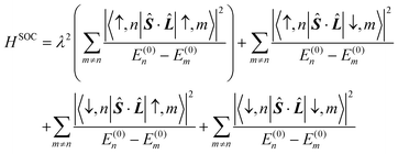
Spin-polarized calculations are adopted within the framework of the density functional theory, especially implemented in the Vienna ab initio simulation package (VASP).60 The projector augmented wave (PAW) pseudopotential method with an energy cutoff of 500 eV is used to describe the interaction between electrons and atomic nuclei.61 The electronic exchange correlation function is expressed by the Perdew–Burke–Ernzerhof (PBE) functional under the generalized gradient approximation (GGA).62 The convergence criterion is 10−6 eV for total energies and 0.01 eV Å−1 for force. A vacuum layer of about 25 Å is added to prevent the interaction between layers.63 The PBE + U approach was used to describe the strong correlation effect for the 3d orbital of the Cr atom, in which the values of U and J are 4.03 eV and 0.96 eV, respectively.47Total MAE is the sum of SOC-MAE and shape-MAE. The calculation of SOC-MAE is based on the second-order perturbation theory, and the Hamiltonian containing spin–orbit coupling interaction (SOC) can be written as:
![[L with combining circumflex]](https://www.rsc.org/images/entities/b_i_char_004c_0302.gif) correspond to the spin momentum operator and orbital angular momentum operator, respectively. All the derivations are provided in the ESI.† The shape-MAE is caused by the dipole–dipole interaction and is expressed as:
correspond to the spin momentum operator and orbital angular momentum operator, respectively. All the derivations are provided in the ESI.† The shape-MAE is caused by the dipole–dipole interaction and is expressed as:where μ0 is the permeability of vacuum, q is the atomic coordinate of the Cr atom, r is the distance between two magnetic atoms, and M represents the magnetic moment. According to the formula, shape-MAE is only related to the position and magnetic moment of magnetic atoms.
Results and discussion
The optimized lattice constants of the CrSBr monolayer are a = 3.59 Å and b = 4.82 Å, which are in good agreement with previous studies.12,25 The FM and four AFM states are considered for the CrSBr monolayer (Fig. S1†), and the results show that the FM state is the ground state, which is consistent with the experimental result.25 Magnetism mainly stems from the Cr atoms with a magnetic moment of 3μB while the S/Br atoms hold a small opposite magnetic moment, which was shown in the spin density distribution (Fig. 1b).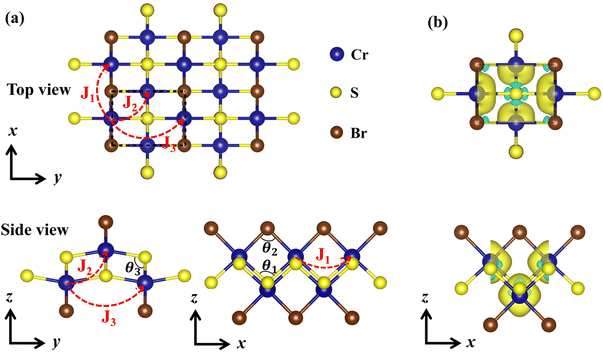 | ||
| Fig. 1 (a) The top view and side view of the CrSBr monolayer. (b) Spin density of the CrSBr monolayer. | ||
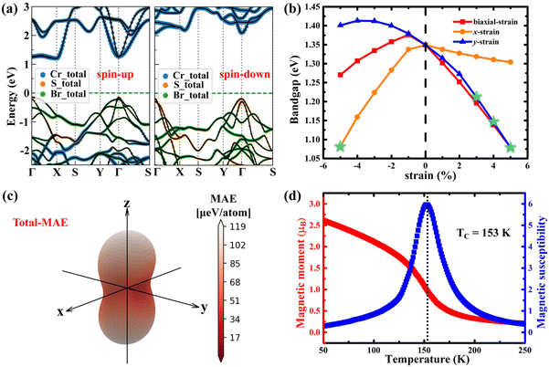
Analysis of the band structure shows that the CrSBr monolayer is a ferromagnetic semiconductor with an indirect bandgap of about 1.35 eV (Fig. 2a), which is in good agreement with the optical band gap measured in the experiment (1.25 ± 0.07 eV).25 Detailed analysis of the atomic-resolved band structure illustrates that the conduction band around the Fermi level is dominated by orbitals of Cr atoms, whereas the valence band is dominated by hybridized orbitals of Br and S atoms, which agree with the results of the density of states (DOS) as shown in Fig. S2.† Analysis of the orbital-resolved DOS shows that the conduction band minima and valence band maxima are mainly occupied by the dx2−y2 orbits of the Cr atom and py orbits of S and Br, respectively.
Fig. S3† shows that the CrSBr monolayer remains in ferromagnetic order under compression and tension strains (from −5% to 5%) and the strain has little effect on the lattice structures and magnetic moment. By applying external strain along different directions, the band-gap of the CrSBr monolayer can be flexibly adjusted from about 1 eV to 1.4 eV (Fig. 2b). Interestingly, an increase in strain along the x and y directions is accompanied by a shift from an indirect to a direct band gap (Fig. 2b). The detailed band structure of the CrSBr monolayer under different strains is shown in Fig. S4–S6.† The reason may be that the applied strain causes a splitting of the band along the X–Γ direction and changes the position of the conduction band bottom from the X to the Γ point.
The magnetocrystalline anisotropy energy (SOC-MAE) of CrSBr bulk was first calculated using the second-order perturbation theory in three directions (the [100], [010], and [001] directions) as shown in Table 1. Obviously, the energy of the y axis (the [010] direction) is lower than that of the z axis (the [001] direction), and the x axis (the [100] direction) has the highest energy (the energy order is y < z < x). This is not consistent with the results of the experiment (y < x < z), which shows that bulk CrSBr exhibits the easy y axis, intermediate x axis, and hard z axis.38,40,49,64 Although the calculated easy magnetic axis is the same as the experimental result (the [010] direction), the measured triaxial MAE by experiment is not well reproduced. Compared to the weak SOC-MAE, shape anisotropy induced by the magnetic dipole–dipole interaction may have an important contribution (shape-MAE).65 The in-plane shape-MAE was also calculated (Table 1), in which rmax = 3000 Å was used to ensure the numerical reliability. Interestingly, after considering the magnetic dipole–dipole interaction, the total-MAE (sum of SOC-MAE and shape-MAE) shows that y, x, and z are indeed the easy, the intermediate, and the hard axis, respectively, reflecting its triaxial anisotropy. These results not only well reproduce the experimental triaxial MAE of bulk, but also demonstrate the important role of the magnetic dipole–dipole interaction (shape-MAE) in this material.
| E [100] | E [010] | E [001] | Energy order of magnetic axes | ||
|---|---|---|---|---|---|
| Bulk | SOC-MAE | 8 | −32 | 0 | y < z < x |
| Shape-MAE | −59 | −40 | 0 | x < y < z | |
| Total-MAE | −51 | −72 | 0 | y < x < z | |
| y < x < z (exp.49,64) | |||||
| Monolayer | SOC-MAE | 24 | −55 | 0 | y < z < x |
| Shape-MAE | −75 | −64 | 0 | x < y < z | |
| Total-MAE | −51 | −119 | 0 | y < x < z | |
The SOC-MAE and shape-MAE of the CrSBr monolayer were also calculated (Table 1), and the results show that this monolayer also possesses triaxial magnetic anisotropy. Moreover, the value of shape-MAE is larger than that of SOC-MAE. The presence of triaxial magnetic anisotropy in the CrSBr monolayer is different from the present in-plane and out-of-plane magnets,7,66 reinforcing the interest in the CrSBr monolayer as a potential host for exotic magnetic states. In order to show more clearly this novel property, the angular dependences of SOC-MAE, shape-MAE, and total-MAE along the three planes (the xz plane, yz plane, and xy plane) and the whole space are presented in Fig. S7† and Fig. 2c. Clearly, the MAE strongly depends on the direction of magnetization in the whole space, which confirms again the strong magnetic anisotropy in this monolayer.
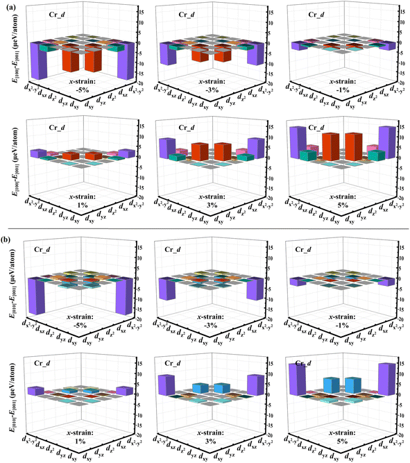
Fig. 3 shows the variation of SOC-MAE, shape-MAE, and total-MAE of the CrSBr monolayer under biaxial and uniaxial strains. The trend of energy change in Fig. 3a is almost the same under the biaxial strains and uniaxial strains along the x direction, while the relative energy is almost constant under strains along the y direction, suggesting the SOC-MAE is sensitive to the strains along the x direction. Fig. 3b shows that the effect of strains on the values of shape-MAE is negligible because of the small changes in the crystal structure and magnetic moment under different strains. Under different strains, Fig. 3c shows the variation of total MAE. Clearly, the variation trend of total-MAE in Fig. 3a and c is consistent, suggesting that the change in the total-MAE is mainly caused by the spin–orbit coupling under different strains, especially the uniaxial strain along the x direction. The corresponding SOC-MAE and total-MAEs through the whole space under different uniaxial strains are plotted in Fig. 4 and Fig. S8, S9.† These figures further confirm that the CrSBr monolayer has strong triaxial magnetic anisotropy and the MAE is most sensitive to uniaxial strain along the x direction.
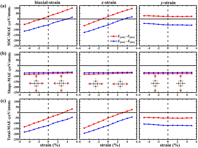 | ||
| Fig. 3 Variation of the SOC-MAE (a), shape-MAE (b), and total-MAE (c) of the CrSBr monolayer under biaxial and uniaxial strains (−5%–5%). The energy is the reference along the [001] direction. | ||
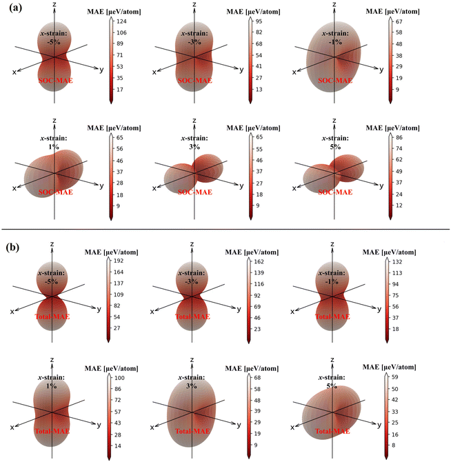 | ||
| Fig. 4 The variation of SOC-MAE (a) and total-MAE (b) for the CrSBr monolayer in the whole space under uniaxial x strain (−5%–5%). | ||
To further elucidate the origin of the strain effect on the SOC-MAE, we first determine separate contributions of the Cr, S and Br atoms to SOC-MAE (Fig. S10†). The results show that the SOC-MAE is mainly contributed by the Cr_d orbitals and Br_p orbitals, which are the most sensitive to external strain. Taking a biaxial tensile strain of 5% as an example, Fig. S10a† shows that the contribution of Cr_d orbitals to the MAE between the [100] and [001] direction is much more than that of the other orbitals. Fig. S10b† shows that the MAE between the directions [010] and [100] is mainly contributed by the Cr_d orbitals and Br_p orbitals. The values of SOC-MAE, of each d orbital of Cr_d orbitals (including dxy, dyz, dz2, dxz, and dx2−y2) and the individual p orbitals of Br_p (including py, pz, and px) were also calculated. Fig. 5 and S11–S15† represent the amount of energy change in the [100], [010] and [001] directions for individual Cr_d and Br_p orbitals under biaxial, x-directional uniaxial and y-directional uniaxial strains, respectively. These figures reveal that the coupling between Cr_dx2−y2 and Cr_dxy orbitals and that between Cr_dz2 and Cr_dyz orbitals are more sensitive to biaxial strain and uniaxial in the x-direction. According to the formula and Tables S3 and S4 given in the ESI,† the Cr_dx2−y2 and Cr_dxy coupling through ![[l with combining circumflex]](https://www.rsc.org/images/entities/i_char_006c_0302.gif) x and
x and ![[l with combining circumflex]](https://www.rsc.org/images/entities/i_char_006c_0302.gif) y in the same spin state and that in different spin states are both equal to 0, while the coupling of these two orbits via
y in the same spin state and that in different spin states are both equal to 0, while the coupling of these two orbits via ![[l with combining circumflex]](https://www.rsc.org/images/entities/i_char_006c_0302.gif) z in the same spin state is not 0, which indicates that the coupling between Cr_dx2−y2 and Cr_dxy will provide a higher spin orbit coupling energy in the z direction. Similarly, the coupling between Cr_dz2 and Cr_dyz orbitals gain a nonzero value only via
z in the same spin state is not 0, which indicates that the coupling between Cr_dx2−y2 and Cr_dxy will provide a higher spin orbit coupling energy in the z direction. Similarly, the coupling between Cr_dz2 and Cr_dyz orbitals gain a nonzero value only via ![[l with combining circumflex]](https://www.rsc.org/images/entities/i_char_006c_0302.gif) x for different spin states, suggesting that the coupling of Cr_dz2 and Cr_dyz orbitals will provide a low spin orbit coupling energy in the y and z directions. The coupling of other orbits can also be derived in the same way according to Tables S3 and S4.† Taking the example of x direction tensile strain, the enhancement of tensile strain weakens the coupling strength of Cr_dx2−y2 and Cr_dxyvia
x for different spin states, suggesting that the coupling of Cr_dz2 and Cr_dyz orbitals will provide a low spin orbit coupling energy in the y and z directions. The coupling of other orbits can also be derived in the same way according to Tables S3 and S4.† Taking the example of x direction tensile strain, the enhancement of tensile strain weakens the coupling strength of Cr_dx2−y2 and Cr_dxyvia ![[l with combining circumflex]](https://www.rsc.org/images/entities/i_char_006c_0302.gif) z in the same spin state, while at the same time, Cr_dz2 and Cr_dyz orbitals in the same spin state via
z in the same spin state, while at the same time, Cr_dz2 and Cr_dyz orbitals in the same spin state via ![[l with combining circumflex]](https://www.rsc.org/images/entities/i_char_006c_0302.gif) x coupling in different spin states and Cr_dz2 and Cr_dxz orbitals via
x coupling in different spin states and Cr_dz2 and Cr_dxz orbitals via ![[l with combining circumflex]](https://www.rsc.org/images/entities/i_char_006c_0302.gif) y in different states are both enhanced, eventually resulting in the lowest energy in the z direction. In addition, the SOC-MAE of individual p-orbitals of the Br atom is less sensitive to strain than that of the individual Cr_d orbitals and the energy change is within 5 μeV. The angular momentum coupling through the individual p-orbitals can also be obtained according to the formula and Table S3 in the ESI.† We also take the example of x-direction tensile strain. The strengthening of the tensile strain is accompanied by a weakening of the
y in different states are both enhanced, eventually resulting in the lowest energy in the z direction. In addition, the SOC-MAE of individual p-orbitals of the Br atom is less sensitive to strain than that of the individual Cr_d orbitals and the energy change is within 5 μeV. The angular momentum coupling through the individual p-orbitals can also be obtained according to the formula and Table S3 in the ESI.† We also take the example of x-direction tensile strain. The strengthening of the tensile strain is accompanied by a weakening of the ![[l with combining circumflex]](https://www.rsc.org/images/entities/i_char_006c_0302.gif) z coupling between Br_px and Br_py in the same spin state, a weakening of the
z coupling between Br_px and Br_py in the same spin state, a weakening of the ![[l with combining circumflex]](https://www.rsc.org/images/entities/i_char_006c_0302.gif) x coupling between Br_py and Br_pz in the same spin state, and a strengthening of the
x coupling between Br_py and Br_pz in the same spin state, and a strengthening of the ![[l with combining circumflex]](https://www.rsc.org/images/entities/i_char_006c_0302.gif) y coupling between Br_px and Br_pz in the same spin state.
y coupling between Br_px and Br_pz in the same spin state.
Because of the importance of TC for the application of 2D magnets, we estimated the TC of the CrSBr monolayer using Monte Carlo simulations based on the Heisenberg model, and the Hamiltonian can be written as
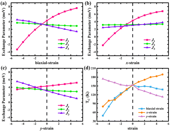 | ||
| Fig. 6 Variation of exchange parameters with biaxial strain (a), uniaxial strain in the x-direction (b), and uniaxial in the y-direction (c), respectively. (d) The changes of TC at different strains. | ||
Summary
In summary, we have investigated the origin of triaxial anisotropic magnetic properties of the air-stable 2D magnetic semiconductor CrSBr using first-principles calculations. The CrSBr monolayer exhibits triaxial anisotropy, which originates from the coexistence of the magnetic dipole–dipole interaction (shape anisotropy) and the spin–orbit coupling interaction (magnetocrystalline anisotropy), and we also unveil that the magnetic shape anisotropy, which has been neglected in most previous works, is of importance for works of weak magnetocrystalline anisotropy. Interestingly, the energy order of the three magnetic axes of the CrSBr monolayer can be tuned by applying strains, in which the SOC-MAE is more sensitive to strains than shape-MAE. Further analysis shows that the enhancement of biaxial and uniaxial x-direction tensile strain weakens the coupling strength of Cr_dx2−y2 and Cr_dxyvia![[l with combining circumflex]](https://www.rsc.org/images/entities/i_char_006c_0302.gif) z in the same spin state while enhancing the coupling strength of Cr_dz2 and Cr_dyzvia
z in the same spin state while enhancing the coupling strength of Cr_dz2 and Cr_dyzvia ![[l with combining circumflex]](https://www.rsc.org/images/entities/i_char_006c_0302.gif) x in different spin states and Cr_dz2 and Cr_dxzvia
x in different spin states and Cr_dz2 and Cr_dxzvia ![[l with combining circumflex]](https://www.rsc.org/images/entities/i_char_006c_0302.gif) y in different spin states, eventually achieving triaxial switching in the process. Besides, the strains also can flexibly adjust the band gap and even change the original indirect band gap to a direct band gap. By using the four ordered spin states, the observed TC (146 K) of the CrSBr monolayer is well reproduced based on Monte Carlo simulations (152 K) and the TC can be increased to 189 K under uniaxial strain in the x direction. Our work gives insights into understanding the MAE of 2D ferromagnetism and paves the way for strain control of switchable magnetic anisotropy and Curie temperature for exploring new spintronic applications.
y in different spin states, eventually achieving triaxial switching in the process. Besides, the strains also can flexibly adjust the band gap and even change the original indirect band gap to a direct band gap. By using the four ordered spin states, the observed TC (146 K) of the CrSBr monolayer is well reproduced based on Monte Carlo simulations (152 K) and the TC can be increased to 189 K under uniaxial strain in the x direction. Our work gives insights into understanding the MAE of 2D ferromagnetism and paves the way for strain control of switchable magnetic anisotropy and Curie temperature for exploring new spintronic applications.
Author contributions
B. Wang: formal analysis, writing – original draft, and funding acquisition; Y. Wu: formal analysis, writing – original draft, and data curation; Y. Bai: supervision and writing – original draft; P. Shi: data curation; G. Zhang: visualization, methodology and funding acquisition; Y. Zhang: writing – review & editing and funding acquisition, C. Liu: writing – review & editing and project administration. All authors checked the manuscript.Conflicts of interest
There are no conflicts to declare.Acknowledgements
This work was financially supported by the National Natural Science Foundation of China (no. 12047517, 12104130, and 11904079), the China Postdoctoral Science Foundation (no. 2020M682274 and 2020TQ0089), the Postgraduate Education Reform and Quality Improvement Project of Henan Province (grant no. YJS2023ZX19), the Scientific Research Key Project Fund of Henan Provincial Education Department (no. 23B140005), and the Innovative Experimental Training Program for College Students of Henan University (no. 20231011011).References
- Y. Liu, C. Zeng, J. Zhong, J. Ding, Z. M. Wang and Z. Liu, Nano-Micro Lett., 2020, 12, 1–26 CrossRef PubMed.
- Y. Tu, Q. Liu, L. Hou, P. Shi, C. Jia, J. Su, J. Zhang, X. Zhang and B. Wang, Front. Phys., 2022, 10, 1078202 CrossRef.
- Y. P. Feng, L. Shen, M. Yang, A. Wang, M. Zeng, Q. Wu, S. Chintalapati and C.-R. Chang, Wiley Interdiscip. Rev.: Comput. Mol. Sci., 2017, 7, e1313 Search PubMed.
- X. Li and J. Yang, Natl. Sci. Rev., 2016, 3, 365–381 CrossRef CAS.
- S. Xing, J. Zhou, X. Zhang, S. Elliott and Z. Sun, Prog. Mater. Sci., 2022, 101036 Search PubMed.
- X. Li and J. Yang, J. Am. Chem. Soc., 2019, 141, 109–112 CrossRef CAS PubMed.
- B. Wang, X. Zhang, Y. Zhang, S. Yuan, Y. Guo, S. Dong and J. Wang, Mater. Horiz., 2020, 7, 1623–1630 RSC.
- C. Huang, J. Feng, F. Wu, D. Ahmed, B. Huang, H. Xiang, K. Deng and E. Kan, J. Am. Chem. Soc., 2018, 140, 11519–11525 CrossRef CAS PubMed.
- N. D. Mermin and H. Wagner, Phys. Rev. Lett., 1966, 17, 1133–1136 CrossRef CAS.
- B. Huang, G. Clark, E. Navarro-Moratalla, D. R. Klein, R. Cheng, K. L. Seyler, D. Zhong, E. Schmidgall, M. A. McGuire, D. H. Cobden, W. Yao, D. Xiao, P. Jarillo-Herrero and X. Xu, Nature, 2017, 546, 270–273 CrossRef CAS PubMed.
- C. Gong, L. Li, Z. Li, H. Ji, A. Stern, Y. Xia, T. Cao, W. Bao, C. Wang, Y. Wang, Z. Q. Qiu, R. J. Cava, S. G. Louie, J. Xia and X. Zhang, Nature, 2017, 546, 265–269 CrossRef CAS PubMed.
- Y. Guo, Y. Zhang, S. Yuan, B. Wang and J. Wang, Nanoscale, 2018, 10, 18036–18042 RSC.
- V. V. Kulish and W. Huang, J. Mater. Chem. C, 2017, 5, 8734–8741 RSC.
- X. Cai, T. Song, N. P. Wilson, G. Clark, M. He, X. Zhang, T. Taniguchi, K. Watanabe, W. Yao, D. Xiao, M. A. McGuire, D. H. Cobden and X. Xu, Nano Lett., 2019, 19, 3993–3998 CrossRef CAS PubMed.
- H. H. Kim, B. Yang, S. Li, S. Jiang, C. Jin, Z. Tao, G. Nichols, F. Sfigakis, S. Zhong and C. Li, Proc. Natl. Acad. Sci. U. S. A., 2019, 116, 11131–11136 CrossRef CAS PubMed.
- C. Wang, X. Zhou, L. Zhou, N.-H. Tong, Z.-Y. Lu and W. Ji, Sci. Bull., 2019, 64, 293–300 CrossRef CAS PubMed.
- K. Sheng, Q. Chen, H.-K. Yuan and Z.-Y. Wang, Phys. Rev. B, 2022, 105, 075304 CrossRef CAS.
- Y. Wu, W. Sun, S. Liu, B. Wang, C. Liu, H. Yin and Z. Cheng, Nanoscale, 2021, 13, 16564–16570 RSC.
- W. Liu, J. Tong, L. Deng, B. Yang, G. Xie, G. Qin, F. Tian and X. Zhang, Mater. Today Phys., 2021, 21, 100514 CrossRef CAS.
- J.-Y. You, Z. Zhang, X.-J. Dong, B. Gu and G. Su, Phys. Rev. Res., 2020, 2, 013002 CrossRef CAS.
- Y. Ren, Q. Li, W. Wan, Y. Liu and Y. Ge, Phys. Rev. B, 2020, 101, 134421 CrossRef CAS.
- Z. S. Zhang, J. Jiang, C. Rasmita, A. Gao, W. Yu and T. Yu, Nano Lett., 2019, 19, 3138–3142 CrossRef CAS PubMed.
- S. Lu, Q. Zhou, Y. Guo and J. Wang, Chem, 2022, 8, 769–783 CAS.
- H. H. Kim, B. Yang, S. Li, S. Jiang, C. Jin, Z. Tao, G. Nichols, F. Sfigakis, S. Zhong, C. Li, S. Tian, D. G. Cory, G. X. Miao, J. Shan, K. F. Mak, H. Lei, K. Sun, L. Zhao and A. W. Tsen, Proc. Natl. Acad. Sci. U. S. A., 2019, 116, 11131–11136 CrossRef CAS PubMed.
- K. Lee, A. H. Dismukes, E. J. Telford, R. A. Wiscons, J. Wang, X. Xu, C. Nuckolls, C. R. Dean, X. Roy and X. Zhu, Nano Lett., 2021, 21, 3511–3517 CrossRef CAS PubMed.
- H. Y. Lv, W. J. Lu, X. Luo, X. B. Zhu and Y. P. Sun, Phys. Rev. B, 2019, 99, 134416 CrossRef CAS.
- J. Y. Chen, X. X. Li, W. Z. Zhou, J. L. Yang, F. P. Ouyang and X. Xiong, Adv. Electron. Mater., 2020, 6, 1900490 CrossRef CAS.
- C. Xu, J. Feng, H. Xiang and L. Bellaiche, npj Comput. Mater., 2018, 4, 1–6 CrossRef CAS.
- Y. Yue, J. Supercond. Novel Magn., 2016, 30, 1201–1206 CrossRef.
- S. D. Guo, Y. L. Tao, K. Cheng, B. Wang and Y. S. Ang, J. Phys.: Condens. Matter, 2022, 34, 505802 CrossRef CAS.
- G. Zhang, F. Guo, H. Wu, X. Wen, L. Yang, W. Jin, W. Zhang and H. Chang, Nat. Commun., 2022, 13, 5067 CrossRef CAS PubMed.
- Y. Bai, R. Shi, Y. Wu, B. Wang and X. Zhang, J. Phys.: Condens. Matter, 2022, 34, 384001 CrossRef CAS PubMed.
- C. Gong and X. Zhang, Science, 2019, 363, eaav4450 CrossRef CAS PubMed.
- J. Su, Y. Bai, P. Shi, Y. Tu and B. Wang, Results Phys., 2023, 51, 106635 CrossRef.
- B. Xu, S. Li, K. Jiang, J. Yin, Z. Liu, Y. Cheng and W. Zhong, Appl. Phys. Lett., 2020, 116, 052403 CrossRef CAS.
- K. Yang, G. Wang, L. Liu, D. Lu and H. Wu, Phys. Rev. B, 2021, 104, 144416 CrossRef CAS.
- Y. J. Bae, J. Wang, A. Scheie, J. Xu, D. G. Chica, G. M. Diederich, J. Cenker, M. E. Ziebel, Y. Bai, H. Ren, C. R. Dean, M. Delor, X. Xu, X. Roy, A. D. Kent and X. Zhu, Nature, 2022, 609, 282–286 CrossRef CAS PubMed.
- C. Boix-Constant, S. Manas-Valero, A. M. Ruiz, A. Rybakov, K. A. Konieczny, S. Pillet, J. J. Baldovi and E. Coronado, Adv. Mater., 2022, 34, 2204940 CrossRef CAS PubMed.
- J. Cenker, S. Sivakumar, K. Xie, A. Miller, P. Thijssen, Z. Liu, A. Dismukes, J. Fonseca, E. Anderson, X. Zhu, X. Roy, D. Xiao, J. H. Chu, T. Cao and X. Xu, Nat. Nanotechnol., 2022, 17, 256–261 CrossRef CAS PubMed.
- T. M. J. Cham, S. Karimeddiny, A. H. Dismukes, X. Roy, D. C. Ralph and Y. K. Luo, Nano Lett., 2022, 22, 6716–6723 CrossRef CAS PubMed.
- D. L. Esteras, A. Rybakov, A. M. Ruiz and J. J. Baldoví, Nano Lett., 2022, 22, 8771–8778 CrossRef CAS PubMed.
- J. Klein, T. Pham, J. D. Thomsen, J. B. Curtis, T. Denneulin, M. Lorke, M. Florian, A. Steinhoff, R. A. Wiscons, J. Luxa, Z. Sofer, F. Jahnke, P. Narang and F. M. Ross, Nat. Commun., 2022, 13, 5420 CrossRef CAS PubMed.
- W. Liu, X. Guo, J. Schwartz, H. Xie, N. U. Dhale, S. H. Sung, A. L. N. Kondusamy, X. Wang, H. Zhao, D. Berman, R. Hovden, L. Zhao and B. Lv, ACS Nano, 2022, 16, 15917–15926 CrossRef CAS.
- S. A. Lopez-Paz, Z. Guguchia, V. Y. Pomjakushin, C. Witteveen, A. Cervellino, H. Luetkens, N. Casati, A. F. Morpurgo and F. O. von Rohr, Nat. Commun., 2022, 13, 4745 CrossRef CAS PubMed.
- D. J. Rizzo, A. S. McLeod, C. Carnahan, E. J. Telford, A. H. Dismukes, R. A. Wiscons, Y. Dong, C. Nuckolls, C. R. Dean and A. N. Pasupathy, Adv. Mater., 2022, 34, 2201000 CrossRef CAS PubMed.
- A. Scheie, M. Ziebel, D. G. Chica, Y. J. Bae, X. Wang, A. I. Kolesnikov, X. Zhu and X. Roy, Adv. Sci., 2022, 9, e2202467 CrossRef PubMed.
- X. Yang, P. Yang, X. Zhou, W. Feng and Y. Yao, Phys. Rev. B, 2022, 106, 054408 CrossRef CAS.
- C. Ye, C. Wang, Q. Wu, S. Liu, J. Zhou, G. Wang, A. Soll, Z. Sofer, M. Yue, X. Liu, M. Tian, Q. Xiong, W. Ji and X. R. Wang, ACS Nano, 2022, 16, 11876–11883 CrossRef CAS PubMed.
- E. J. Telford, A. H. Dismukes, K. Lee, M. Cheng, A. Wieteska, A. K. Bartholomew, Y. S. Chen, X. Xu, A. N. Pasupathy and X. Zhu, Adv. Mater., 2020, 32, 2003240 CrossRef CAS PubMed.
- S. A. López-Paz and F. O. von Rohr, Chimia, 2022, 76, 628 CrossRef.
- Z. Jiang, P. Wang, J. Xing, X. Jiang and J. Zhao, ACS Appl. Mater. Interfaces, 2018, 10, 39032–39039 CrossRef CAS PubMed.
- S. Zhang, Z. Yan, Y. Li, Z. Chen and H. Zeng, Angew Chem., Int. Ed., 2015, 54, 3112–3115 CrossRef CAS PubMed.
- J. Hu, P. Wang, J. Zhao and R. Wu, Adv. Phys.: X, 2018, 3, 1432415 Search PubMed.
- S. Li, Z. Ao, J. Zhu, J. Ren, J. Yi, G. Wang and W. Liu, J. Phys. Chem. Lett., 2017, 8, 1484–1488 CrossRef CAS PubMed.
- Y. Wang, S. S. Wang, Y. Lu, J. Jiang and S. A. Yang, Nano Lett., 2016, 16, 4576–4582 CrossRef CAS PubMed.
- C. Liu, B. Fu, H. Yin, G. Zhang and C. Dong, Appl. Phys. Lett., 2020, 117, 103101 CrossRef CAS.
- P. Liu, S. Liu, M. Jia, H. Yin, G. Zhang, F. Ren, B. Wang and C. Liu, Appl. Phys. Lett., 2022, 121, 063103 CrossRef CAS.
- S.-D. Guo, W.-Q. Mu, J.-H. Wang, Y.-X. Yang, B. Wang and Y.-S. Ang, Phys. Rev. B, 2022, 106, 064416 CrossRef CAS.
- P. Liu, G. Zhang, Y. Yan, G. Jia, C. Liu, B. Wang and H. Yin, Appl. Phys. Lett., 2021, 119, 102403 CrossRef CAS.
- G. Kresse and J. Furthmüller, Phys. Rev. B: Condens. Matter Mater. Phys., 1996, 54, 11169–11186 CrossRef CAS PubMed.
- P. E. Blöchl, Phys. Rev. B: Condens. Matter Mater. Phys., 1994, 50, 17953–17979 CrossRef PubMed.
- J. P. Perdew, K. Burke and M. Ernzerhof, Phys. Rev. Lett., 1996, 77, 3865–3868 CrossRef CAS PubMed.
- Y. Zhu, X. Wang and W. Mi, J. Mater. Chem. C, 2019, 7, 2049–2058 RSC.
- E. J. Telford, A. H. Dismukes, R. L. Dudley, R. A. Wiscons, K. Lee, D. G. Chica, M. E. Ziebel, M. G. Han, J. Yu, S. Shabani, A. Scheie, K. Watanabe, T. Taniguchi, D. Xiao, Y. Zhu, A. N. Pasupathy, C. Nuckolls, X. Zhu, C. R. Dean and X. Roy, Nat. Mater., 2022, 21, 754–760 CrossRef CAS PubMed.
- F. Xue, Y. Hou, Z. Wang and R. Wu, Phys. Rev. B, 2019, 100, 224429 CrossRef CAS.
- B. Wang, Y. Zhang, L. Ma, Q. Wu, Y. Guo, X. Zhang and J. Wang, Nanoscale, 2019, 11, 4204–4209 RSC.
- H. Xiang, E. Kan, S.-H. Wei, M.-H. Whangbo and X. Gong, Phys. Rev. B: Condens. Matter Mater. Phys., 2011, 84, 224429 CrossRef.
Footnote |
| † Electronic supplementary information (ESI) available. See DOI: https://doi.org/10.1039/d3nr02518g |
| This journal is © The Royal Society of Chemistry 2023 |

