
Phosphorus-modified cobalt single-atom catalysts loaded on crosslinked carbon nanosheets for efficient alkaline hydrogen evolution reaction†
Yucong
Huang‡
ab,
Zhiyun
Hu‡
 a,
Liang-ai
Huang
a,
Zongpeng
Wang
a,
Zhiping
Lin
a,
Shijie
Shen
a,
Wenwu
Zhong
*a and
Jiaqi
Pan
*b
a,
Liang-ai
Huang
a,
Zongpeng
Wang
a,
Zhiping
Lin
a,
Shijie
Shen
a,
Wenwu
Zhong
*a and
Jiaqi
Pan
*b
aSchool of Materials Science and Engineering, Taizhou University, 318000, Zhejiang, China. E-mail: zhongww@tzc.edu.cn
bKey Laboratory of Optical Field Manipulation of Zhejiang Province, and Key Laboratory of ATMMT Ministry of Education, Department of Physics, Zhejiang Sci-Tech University, 310000, Zhejiang, China. E-mail: panjq@zstu.edu.cn
First published on 31st January 2023
Abstract
Efficient and low-cost transition metal single-atom catalysts (TMSACs) for hydrogen evolution reaction (HER) have been recognized as research hotspots recently with advances in delivering good catalytic activity without noble metals. However, the high-cost complex preparation of TMSACs and insufficient stability limited their practical applications. Herein, a simple top-down pyrolysis approach to obtain P-modified Co SACs loaded on the crosslinked defect-rich carbon nanosheets was introduced for alkaline hydrogen evolution, where Co atoms are locally confined before pyrolysis to prevent aggregation. Thereby, the abundant defects and the unsaturated coordination formed during the pyrolysis significantly improved the stability of the monatomic structure and reduced the reaction barrier. Furthermore, the synergy between cobalt atoms and phosphorus atoms was established to optimize the decomposition process of water molecules, which delivers the key to promoting the slow reaction kinetics of alkaline HER. As the result, the cobalt SAC exhibited excellent catalytic activity and stability for alkaline HER, with overpotentials of 70 mV and 192 mV at current densities of −10 mA cm−2 and −100 mA cm−2, respectively.
Introduction
Transition metal SACs have attracted extensive attention for their high activity benefitting from unique electron properties and great electrochemical active surface area (ECSA).1,2 Moreover, due to the high abundance of transition metals, TMSACs are promising competitors to substitute the expensive noble metal catalysts.3–5 Therefore, massive transition metal SACs for electrocatalysis, including hydrogen evolution have been recently reported.6–14 For example, Lim et al. designed a Fe-based SAC anchored to single- and double-vacancy sites of the defective graphene structures for HER, obtaining a superb performance with ultra-low overpotential.15 However, owing to the complex high-cost preparation processes and the instability of the monatomic structure, the development of SACs is still challenging, and it has been difficult for most of the SACs to achieve industrialization.16Typically, SACs are fabricated on carbon supports using deposition processes such as atomic layer deposition.17,18 However, both the deposition methods and the carbon substrates, such as graphenes suffer from complex and high-cost processes,19 which inevitably increases the synthesis cost and are not conducive to large-scale production against the original intention of substituting noble metals. Hence, exploring simple and low-cost synthesis methods while ensuring high activity and stability is of great significance for the development and application of SACs.20 Top-down synthesis strategies, which have simple synthesis procedures and are low cost compared to their bottom-up counterparts, have been considered efficient methods to fabricate SACs.21 In particular, high-temperature pyrolysis provides a flexible route to synthesize carbon nanomaterials with metal loadings.22–24 Moreover, after the bulk structures were downsized into nanostructures of SACs, abundant defects and unsaturated sites can be created, leading to unique electronic structures and catalytic mechanisms.25 Therefore, top-down pyrolysis synthesis procedures for SACs were recently widely studied to pursue simple and low-cost synthesis methods. For instance, Chen and co-workers prepared the Fe SAC supported on N-doped carbon by transforming Fe(acac)3 trapped in the ZIF-8 using the pyrolysis method, with excellent performance for the oxygen reduction reactions.26
Another factor that impedes the application of SACs is the instability of the monatomic structure, which is caused by the weak binding between metal atoms and substrates.27 One of the solutions to stabilize the metal atoms is to strengthen the binding by heat treatment; however, aggregation is more likely to occur during the high-temperature process.28 Hence, confining the metal atoms before the heat treatment was proposed for the preparation of SACs.29,30 Yang et al. adopted an efficient confined pyrolysis strategy to prepare single iron sites in periodic mesoporous nitrogen-doped carbon, which exhibited an excellent activity for the oxygen reduction reaction due to abundantly exposed active sites.31 Moreover, defects on the substrates were considered to be able to obviously change the charge distribution between atoms, thus strengthening the binding between metal atoms and the substrates.32,33 Tang et al. developed high-loading molybdenum SACs for efficient oxygen reduction reaction, in which, the Mo single atoms were trapped and stabilized on the substrate as a result of the defect-trapping effect.34
In addition, involving the adsorption and dissociation process of water molecules, the HER is more difficult to proceed under alkaline conditions, which has been a great challenge in the design of electrocatalysts.35–38 Thus, optimizing the adsorptions of H2O˙ and OH˙ is the key to improving the slow reaction kinetics in the widely-used commercial alkaline electrolytes. The imperfection of the active site (such as vacancies, defects, and low-coordination) has been proved to significantly promote the process.39,40 For example, Zhang and co-workers reported a NiO nanorod catalyst with abundant oxygen vacancies synthesized via a facile cation exchange strategy, exhibiting an excellent alkaline HER activity due to the optimized energy barrier for water dissociation.41 In some cases, the heteroatom sites in the catalyst can also promote the water dissociation process by decreasing the free-energy barrier.42–44 Hence the introduction of a synergistic effect between the active sites and heteroatoms, such as nitrogen and phosphorus atoms, is desirable to further boost the alkaline HER performance.45,46 However, due to the difficulty to regulate the coordination of single atom structure, those aforementioned methods are difficult to be applied to the transition metal SACs for HER.
Herein, a phosphorus-modified cobalt SAC for efficient alkaline HER supported on crosslinked carbon nanosheets prepared by top-down pyrolysis was introduced. After combining nanosized chitin with phytic acid, both are common renewable resources on the earth, the defect-rich crosslinked carbon nanosheets can be obtained by pyrolysis. Wherein the phytic acid has a strong ability to chelate the metal ions, hence the cobalt ions in the solution can be captured and confined, and the cobalt SAC supported on carbon nano substrates can be easily prepared after pyrolysis. Benefiting from the large ECSA and high intrinsic activity, the cobalt SAC exhibited a superb HER catalytic activity with an overpotential of 70 mV at a current density of 10 mA cm−2 under an alkaline environment. Furthermore, the DFT calculations revealed that the abundant carbon defects and the unsaturated coordination sites not only improved the HER catalytic activity under alkaline conditions of the cobalt SAC but also greatly enhanced the stability of the cobalt monatomic structure. In addition, the synergy between the cobalt atom and the phosphorus atom brought by phytic acid greatly optimized the water dissociation process, which is the major barrier to boosting HER under an alkaline environment. This work provides a new way to obtain cobalt SACs with excellent activity as well as a low-cost process, and SACs of other transition metals can also be prepared by virtue of the universality of the synthesis method.
Results and discussion
Chitin is the second largest renewable resource on the earth and is a polymer of N-acetylglucosamine chains, which are bound closely by hydrogen bonds between the amide groups and hydroxyl groups, forming a high physical strength.47,48 As shown in Fig. 1, the hydrogen bonds were broken and the chitins were turned into nanosized materials by mechanical exfoliation such as ultrasonication or high-energy ball milling under acidic conditions (Fig. S1a†).49 After the physical treatment, the amide groups of chitins were deacetylated to form amino groups and became chitosan chains.50 In this process, phytic acid not only can provide an acidic environment through its phosphate but also can combine with the amino and hydroxyl groups on the chains to form a cross-linked structure and prevent the chains from reforming hydrogen bonds in the subsequent process (Fig. S1b†).51–53 More importantly, phytic acid has a strong complexation ability to metal ions in a neutral pH environment (Fig. S1c†).54 Therefore, the crosslinked structure of cobalt-phytic-chitosan chains can be formed by adding cobalt ions to the cross-linked structure of the above phytic acid chitosan chains after adjusting the pH value. After further pyrolysis, cross-linked carbon nanosheets loaded with cobalt atoms were obtained.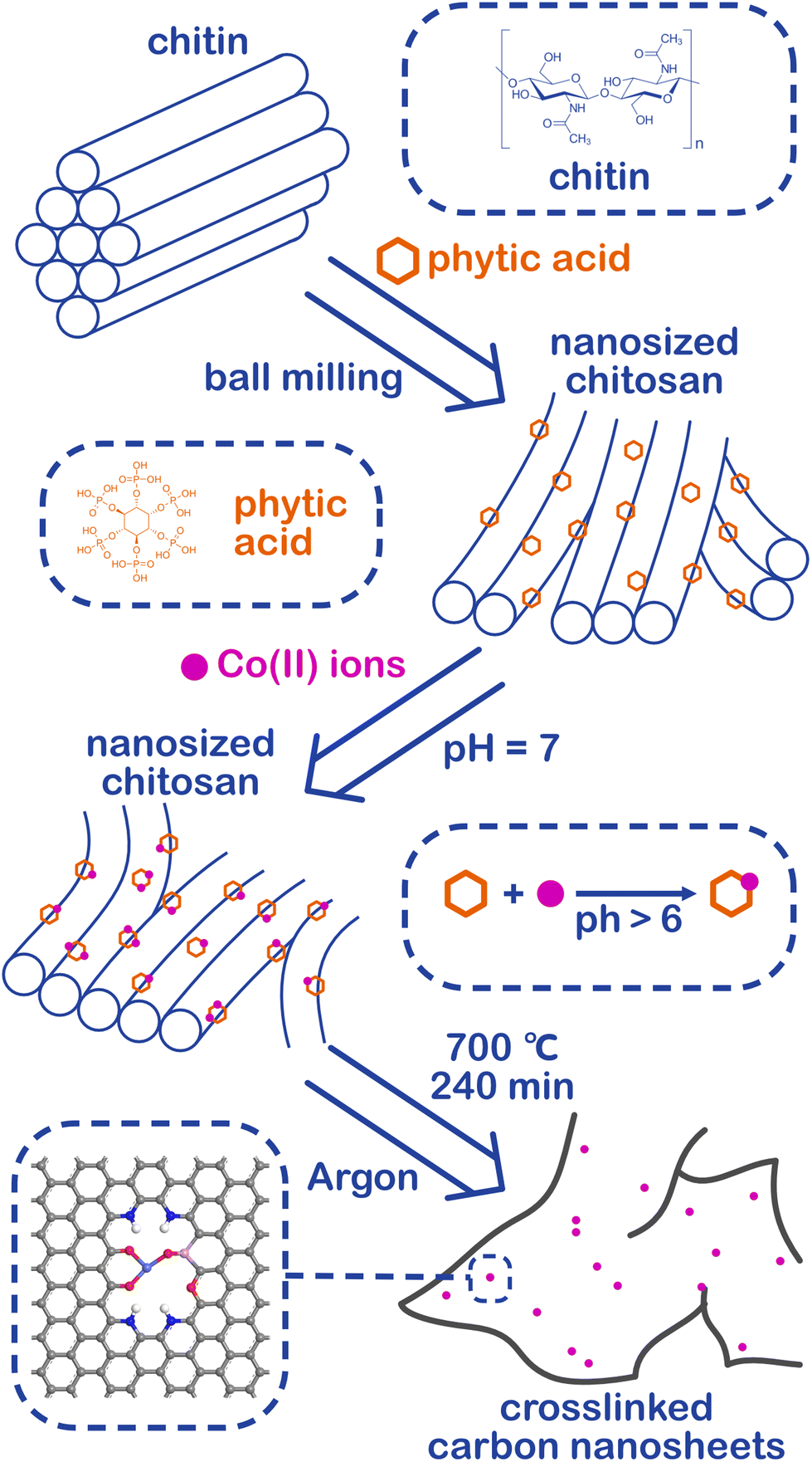 | ||
| Fig. 1 Preparation flow chart of cobalt SACs loaded crosslinked carbon nanosheets (Co@CCNS). | ||
The morphology of the catalysts was characterized using a scanning electron microscope (SEM). As shown in Fig. S2a–c,† chitin was successfully nanosized by ball milling, and the crosslinked carbon nanosheet structure was obtained after pyrolysis. To investigate the effects of different pyrolysis temperatures on the prepared catalysts, the morphology and structure of a series of catalysts pyrolyzed at different temperatures were characterized. After adding cobalt ions, the crosslinked nanostructure was maintained in the catalysts (Fig. S2d–f†). However, when the pyrolysis temperature reaches 800 °C, nanoclusters of the cobalt complex were found on the carbon nanosheets (Fig. S2f†). Fig. 2b exhibits the transmission electron microscope (TEM) images of the sample Co@CCNS-700, in which the carbon nanosheets have no regular graphite lattice stripes compared to common carbon-based materials like graphene. This demonstrated that the chitin chains formed carbon layers with rich graphite defects instead of regular graphite layers. The images of the spherical aberration-corrected transmission electron microscope (ACTEM) (Fig. 2c and d) present the cobalt atoms anchored on the carbon nanosheets, which are dispersed as single atoms.
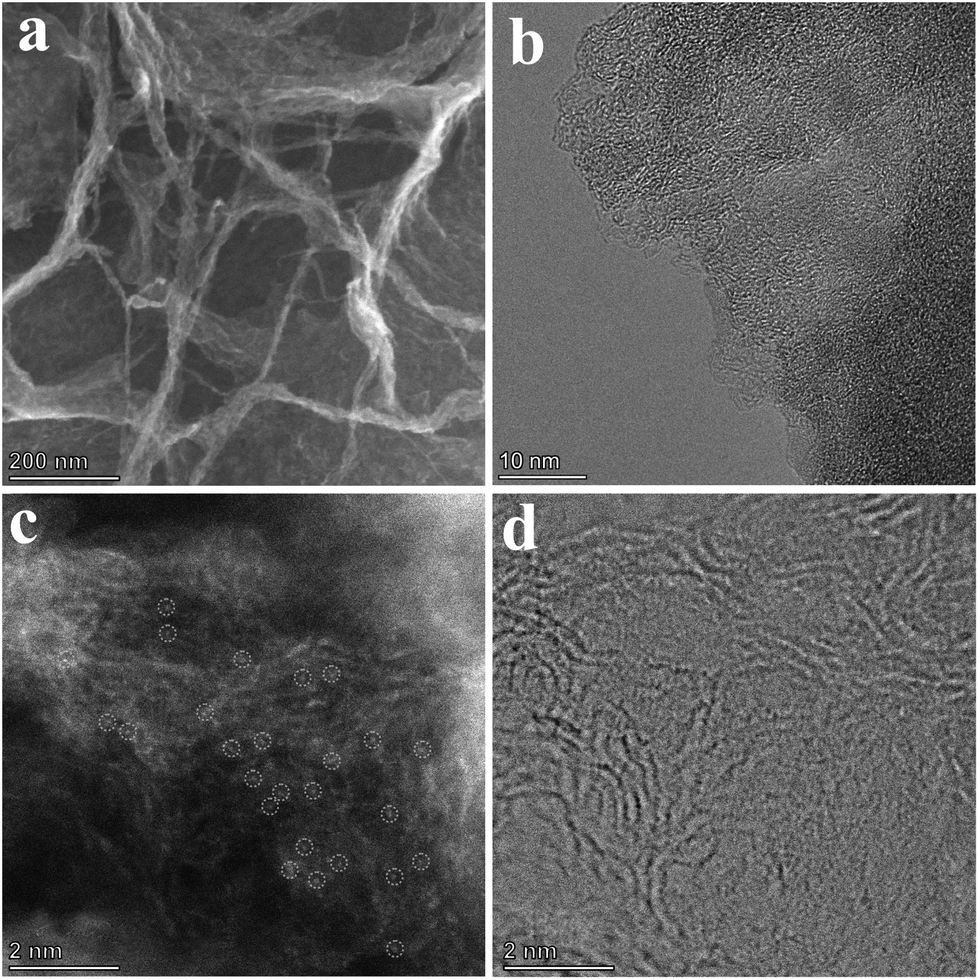 | ||
| Fig. 2 (a) SEM (b) TEM and (c and d) ACTEM images of Co@CCNS-700. | ||
X-ray diffraction (XRD), Raman spectroscopy, and X-ray photoelectron spectroscopy (XPS) were employed to reveal the composition and chemical structure of the catalysts.55 In the XRD pattern shown in Fig. 3a, the samples Co@CCNS-600 and Co@CCNS-700 only showed a diffraction peak at 23.5° corresponding to the (002) crystal plane of graphite. When the pyrolysis temperature was raised to 800 °C, the characteristic peaks of Co2P (PDF#54-0413) and Co3O4 (PDF#43-1003) appeared, consistent with the results of SEM, and imply that there are oxygen atoms and phosphorus atoms in the coordination environment of cobalt atoms. For comparison, the sample, Co2P/CCNS-800 was prepared by adding the twice amount of phytic acid content, which only exhibited the characteristic peaks of Co2P, indicating that the proportion of phosphates was determined by phytic acid content. In addition, the sample Co3O4/CCNS-700 prepared by replacing phytic acid with hydrochloric acid showed a strong diffraction peak for Co3O4 after pyrolysis at a temperature of 700 °C. This demonstrates that phytic acid not only served as a phosphorus source but also anchored the cobalt atoms on the carbon substrate to prevent aggregation during the heat treatment. The Raman spectra of the catalysts are shown in Fig. 3b, which show a D band (defect, 1300–1380 cm−1) and a G band (graphite, 1500–1650 cm−1).56,57 Wherein, the former comes from the vibration of carbon atoms on carbon defects, and the latter is formed by the vibration of graphitized carbon atoms. The intensity ratio of the D band to the G band (ID/IG) reflects the content of defects in the graphite carbon.58 Compared to graphene (typical ID/IG value of 0.3), the ID/IG ratio of Co@CCNSs is significantly higher, representing a higher content of carbon defects.59
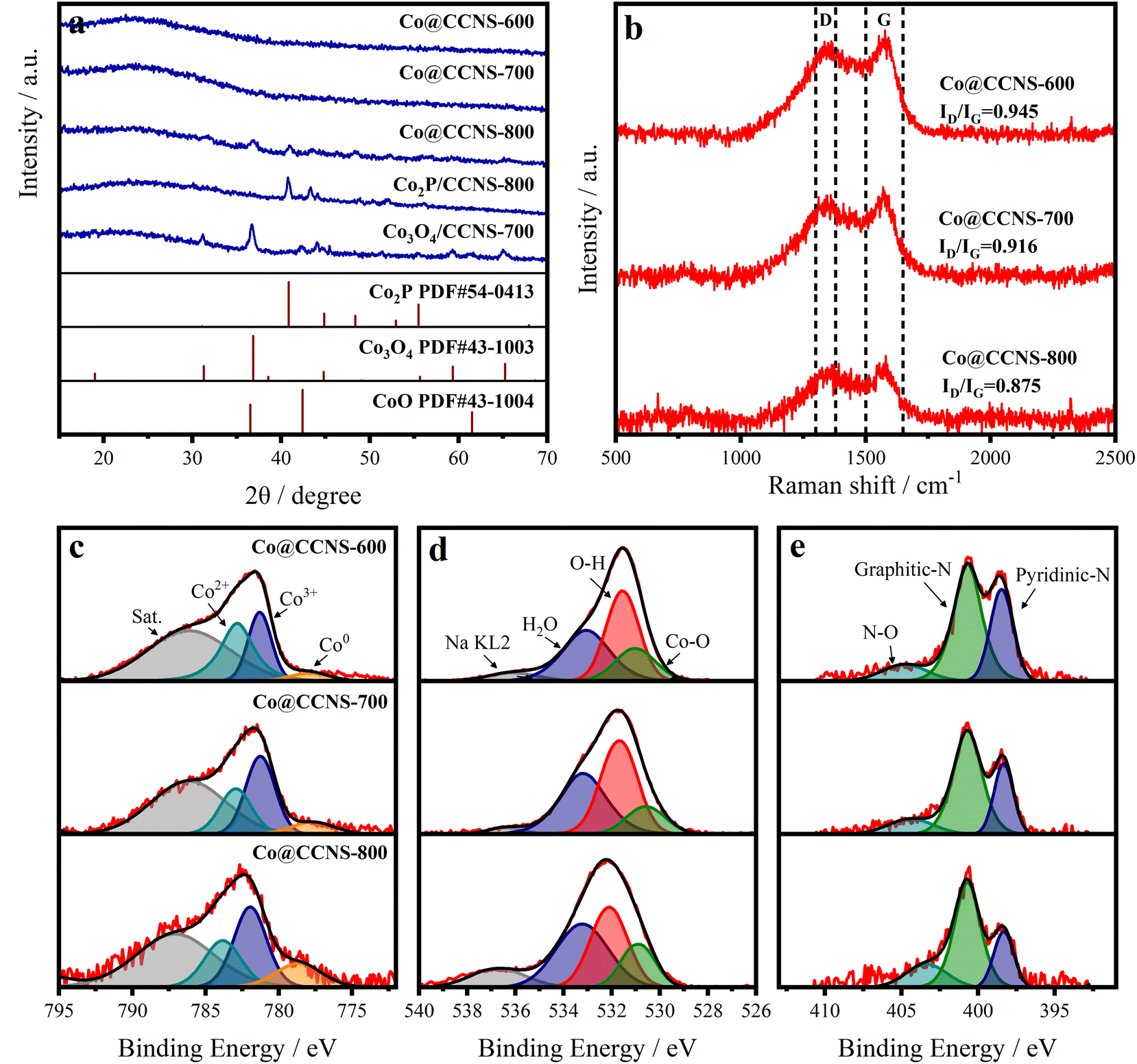 | ||
| Fig. 3 (a) XRD, (b) Raman spectra of Co@CCNSs. High-resolution XPS spectra of (c) Co 2p, (d) O 1s, and (e) N 1s of Co@CCNSs. | ||
Fig. S4† presents the XPS spectra of Co@CCNS-700, indicating the existence of C, O, P, N, and Co species, in which, the nitrogen comes from the acetylamino of chitin. The high-resolution XPS spectra of Co 2p3/2 in Fig. 3c were fitted by the peaks of Co2+, Co3+, and Co0 at the binding energies of about 783.0 eV, 781.3 eV, and 779.1 eV respectively.60 The peaks of Co2+ and Co3+ were considered as contributions of Co–O binding, while the peaks of Co0 were formed by Co–P binding. With the increase of pyrolysis temperatures, the content ratio of Co0 was obviously raised, which can be explained by the formation of Co2P. In the aspect of O 1s XPS spectra shown in Fig. 4d, the content ratio of Co–O binding at the binding energy of 531.0 eV decreased as the pyrolysis temperature increased from 600 °C to 700 °C, resulting from the substitution of oxygen atoms bound to cobalt by phosphorus atoms.61 Meanwhile, the content ratio of Co–O binding increased due to the aggregation of cobalt atoms and the formation of Co3O4 when the pyrolysis temperature reached 800 °C. The XPS spectra of N 1s in Fig. 4e were fitted by the peaks of N–O, graphitic nitrogen, and pyridinic nitrogen at the binding energy of around 404.8 eV, 400.7 eV, and 398.5 eV respectively.62 The graphitic nitrogen and pyridinic nitrogen represent the nitrogen atoms that replaced the carbon atoms in graphite layers and edges of defects respectively, while the intensity ratio of their peaks further demonstrated the high content of carbon defects.63 Fig. S5† shows the XPS spectra of P 2p, which show P–C and P–O species. As the pyrolysis temperature increased and the level of phosphating and carbonization increased, the content ratio of P–O species decreased significantly, leading to more P atoms entering the carbon substrate. The elemental content of the catalysts obtained using XPS is given in Table S1,† which indicated that the carbon contents increased with the rise in pyrolysis temperature. It can be inferred that the pyrolysis of the sample Co@CCNS-600 is not complete, therefore, 700 °C would be the optimum pyrolysis temperature to prevent the cobalt atoms from agglomerating while fully pyrolysed.
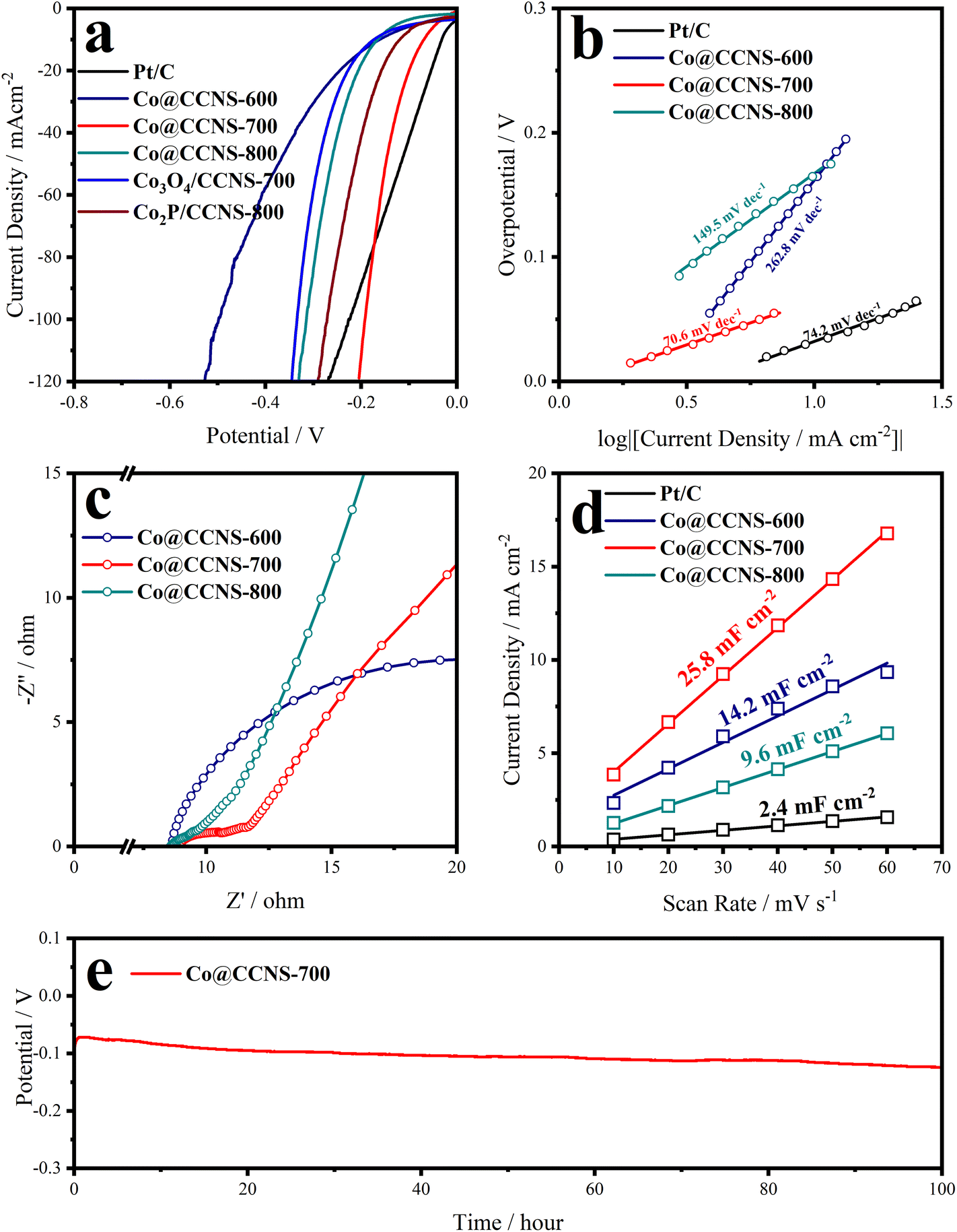 | ||
| Fig. 4 (a) 95% iR-corrected linear sweep voltammetry (LSV), (b) Tafel slopes, (c) electrochemical impedance spectroscopy, and (d) the electric double layer capacitances from current-scan rate relationships at 1.0 V (vs. RHE) plots of Co@CCNSs. (e) Electrochemical stability test of Co@CCNS-700 under a fixed current density of 10 mA cm−2. | ||
The iR-corrected LSV plots of the catalysts under alkaline electrolyte are shown in Fig. 4a, to evaluate their catalytic activities of HER, in which the sample Co@CCNS-700 exhibits an excellent activity, with overpotentials of 70 mV and 192 mV at current densities of −10 mA cm−2 and −100 mA cm−2, respectively. The active components in the sample Co@CCNS-800 are Co3O4 and Co2P, therefore, it showed activity between the sample Co3O4/CCNS-700 and sample Co2P/CCNS-800. For the sample Co@CCNS-600, it shows the worst catalytic activity among all the catalysts owing to its insufficient pyrolysis. The iR-corrected LSV plots based on the current mass ratio are shown in Fig. S6a.† Due to the light mass of carbon and the low level of metal loading, the samples Co@CCNSs showed satisfactory activity compared to commercial Pt/C with the same mass. Tafel slopes calculated from the LSV data are plotted in Fig. 4b, reflecting the reaction kinetic characteristics of the catalysts. The sample Co@CCNS-700 gained the lowest Tafel slope of 70.6 mV dec−1 among the catalysts, indicating its fast HER kinetic. Besides, the Tafel slope implies that the rate-determining step of Co@CCNS-700 is the Heyrovsky step rather than the Volmer step, meaning that the water dissociation process is no longer the major factor restricting the reaction.64,65 This explains why Co@CCNS-700 has a better HER catalytic activity in alkaline electrolytes compared to other samples. Additionally, electrochemical impedance spectroscopy was used to evaluate the electrolyte resistances (Rs) and charge transfer resistances (Rct) of the catalysts, as shown in Fig. 4c and Table S3.† The samples Co@CCNSs have similar Rs and the sample Co@CCNS-700 has the lowest Rct, demonstrating its great electron transfer capability. The current densities of cyclic voltammetry within a potential region where no redox processes take place are linearly related to the scan rates, where half of the slope is equal to the double-layer capacitance (Cdl). Meanwhile, the Cdl is proportional to the ECSA of catalysts, which is an important factor affecting the catalytic activity, and is shown in Fig. 4d. Due to the large specific surface area of the crosslinked carbon nanosheet structures and monoatomic dispersion of the active sites, the catalysts obtained showed considerable ECSA than Pt/C, especially the sample Co@CCNS-700, which gained a Cdl of 25.8 mF cm−2. In addition, intrinsic activity is another crucial factor determining the performance of catalysts, which means the activity of a single active site. In order to reveal the intrinsic activities of the catalysts, the LSV plots were normalized by Cdl to exclude the effect of ECSA, as shown in Fig. S6b.† The intrinsic activity of the sample Co@CCNS-700 is significantly higher than that of Co@CCNS-600 and Co@CCNS-800, which indicated that its superior catalytic activity comes from both ultra-high ECSA and intrinsic activity, and confirmed that the component of its active sites is different from that of Co3O4 and Co2P. Moreover, the electrochemical stability test under a constant current density of −10 mA cm−2 for 100 hours (Fig. 4e) indicated the great stability of the sample Co@CCNS-700.
The X-ray absorption spectrum was used to study the coordination of cobalt atoms in the sample Co@CCNS-700, as shown in Fig. 5. The normalized XANES spectra of cobalt k-edge in Fig. 5a contain the coordination and valence information of cobalt atoms.66 According to the fingerprinting effect, the coordination structure of the absorption atoms can be qualitatively analyzed by comparing the characteristics of pre-edge peaks.67 Compared to the spectra of standard samples, the pre-edge peak of Co@CCNS-700 highly coincides with that of the standard Co3O4, demonstrating that the coordination number of cobalt atoms was 4. Meanwhile, the energy at the derivative extremum of XANES is linearly related to the valence states of the absorption atoms. By the linear fitting of the energy at derivative extremum of standard samples, the average valence state of cobalt atoms of the sample Co@CCNS-700 was found to be 1.48. Furthermore, the coordination structure of the absorption atom can be quantitatively analyzed by Fourier transform or wavelet transform on extended X-ray absorption fine structure (EXAFS) data.68,69Fig. 5b shows the R-space plots of the samples obtained by Fourier transform on EXAFS data, exhibiting the coordination of different species and their relative spatial positions. In the plot of the sample Co@CCNS-700, strong coordination appeared at near 1.6 Å from the cobalt atoms. Compared with the standard samples and combined with the conclusions of XPS, this is likely to be Co–O binding or Co–P binding. Meanwhile, in the vicinity of 3 Å from the central cobalt atom of the sample Co@CCNS-700, there is basically no Co–Co coordination as in the standard sample, indicating that cobalt atoms are distributed discretely on the carbon substrate. The same results were obtained from the EXAFS wavelet transform plots, as shown in Fig. 5c. It is worth noting that the initial phase in EXAFS data will be ignored in the process of Fourier transform or wavelet transform, as such, the obtained spatial distance will be smaller than the actual value.70Fig. 5d–f are the R-space (containing real part and imaginary part) and k-space plots of the sample Co@CCNS-700 and its fitting, where the fitting result is that there are three oxygen atoms coordinated at 2.01 Å and one phosphorus atom coordinated at 3.18 Å from the central cobalt atom (Table S2†).
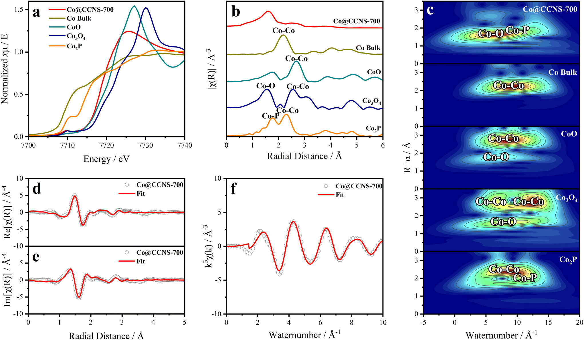 | ||
| Fig. 5 (a) Normalized X-ray absorption near edge structure (XANES) spectra of cobalt k-edge in Co@CCNS-700. (b) Fourier transform and (c) wavelet transform on extended X-ray absorption fine structure (EXAFS) data of Co@CCNS-700. Fittings of (d) real part and (e) imaginary part of R-space and (f) k-space EXAFS plots of Co@CCNS-700. | ||
To further understand the HER reaction process of the cobalt SAC at the atomic level, DFT calculations were conducted to study the active sites and the reaction mechanism. According to the experimental results, the coordination environment near the Co atom was determined as three O atoms, and one P, with N atoms, determined nearby without coordination. Defect models were not first established (Fig. S9,† CoO3PN4), while these structures had high binding energies and high formation energies (Fig. 6a), which implied energetically unfavored Co combination and thermodynamically unstable substrates. We hypothesize that the neutral O atoms have little interaction with Co and the O in the planar six-member ring results in high steric hindrance. Therefore, anionic O out of the six-member ring was investigated, featuring some carbon defects, which were determined by experimental characterization. More charge exchanges were found in these structures (Fig. S10†), resulting in significantly favorable binding energies and formation energies. After performing structure optimization, the parameters of these structures are very close to the fitting of EXAFS, resulting in three oxygen atoms coordinated at 2.015 Å and one phosphorus atom coordinated at 3.147 Å. In addition, corresponding four-coordinated structures were also established to reveal the effect of the lack of oxygen coordination. The adsorption-free energy of atomic hydrogen (ΔGH*) is the most important parameter for evaluating HER activity. An optimum HER catalytic site should have a near-zero ΔGH* value for steady hydrogen adsorption as well as desorption. Hydrogen adsorption structures at different sites were explored and the ΔGH* for each site are shown in Fig. S9† and Fig. 6b. In the case of the Co site, four-coordinated structures have weak hydrogen adsorption (ΔGH* = 0.34 and 0.29 eV), while three-coordinated structures show an enhanced ΔGH* of −0.17 and −0.31 eV. The partial densities of states were further calculated to uncover the physical origin (Fig. S11†). The results indicate that the dissociation of one oxygen to Co results in an energetic upshift of d orbitals and then leads to a stronger hydrogen affinity.
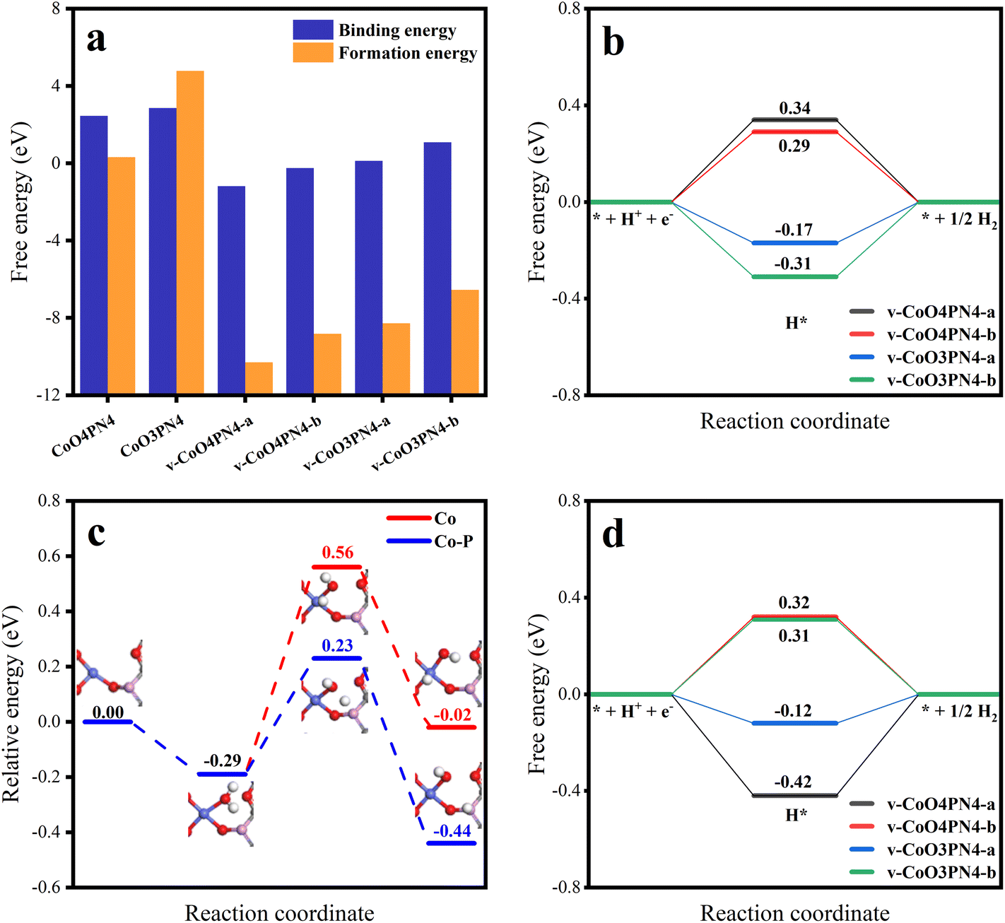 | ||
| Fig. 6 (a) Binding energies and formation energies of CoO4PN4, CoO3PN4, v-CoO4PN4-a, v-CoO4PN4-b, v-CoO3PN4-a, and v-CoO3PN4-b. (b) H adsorption free energy at Co sites in v-CoO4PN4-a, v-CoO4PN4-b, v-CoO3PN4-a, and v-CoO3PN4-b. (c) Relative free energy of water splitting reaction pathway on Co site and Co–P cooperation on v-CoO3PN4. (d) H adsorption free energy at P sites in v-CoO4PN4-a, v-CoO4PN4-b, v-CoO3PN4-a, and v-CoO3PN4-b. | ||
In the above experimental results of SEM, XPS, and XAS, there are N atoms in the catalyst structure. According to the results of XAS, no chemical coordination with the N atom was found on the active site of the Co atom, which means that the N atom may not directly participate in the catalytic process of HER, but it may affect the stability of the structure. To further explore the issue, we established a series of structures of different defects and N-atom sites (Fig. S14†) and calculated their single-atom stability and structural stability (Table S6†). The results not only verified the conclusion that defects can increase the stability of the single-atom structure but also found that when N atoms appear at the edge of defects, the formation energy of structures is significantly reduced. This means that N atoms at the edge of defects stabilize the structure of carbon defects, which corresponds to the abundant pyridinic N in XPS results. Therefore, we believe that N atoms mainly play a role in stabilizing the edge of defects, thus improving the stability of the overall structure.
Meanwhile, it is more difficult for the HER process in the alkaline electrolyte to compare the acid electrolyte because of the involvement of adsorption and dissociation of water molecules. Therefore, water adsorption-free energy was also investigated, and the same tendency was found that the unsaturated oxygen coordination led to a stronger adsorption capacity for water molecules (Fig. S12†). Considering the binding energy and hydrogen affinity, the v-CoO3PN4 structure was selected to study the H2O dissociation process. Fig. 6c shows the corresponding reaction pathways on the Co site and Co–P cooperation on v-CoO3PN4, reflecting the synergistic effect of the Co atom and P atom on the water dissociation process. The H2O molecule is likely captured by the exposed Co sites as the initial states with an energy decreasing of 0.29 eV. As the water molecule splits into OH* and H* on the Co atom, two situations may occur in the reaction process; both intermediates remain on the Co atom, or the H* transfer to the P atom, leaving the OH* adsorbed by the Co atom. The H2O dissociation barriers of the two paths are 0.95 eV and 0.52 eV, indicating that the latter is the better pathway, and the synergy between cobalt atoms and phosphorus atoms significantly optimized the water dissociation process in alkaline HER. Furthermore, the ΔGH* of the P sites was also estimated to evaluate whether the Heyrovsky step on the P sites will go on the wheels after accepting the H*. As shown in Fig. 6d, the P sites also exhibit satisfactory hydrogen adsorption capacity with a ΔGH* of −0.12 eV, demonstrating that the hydrogen desorption can proceed without an additional proton transfer process after H2O dissociation. This implied that the phosphorus atoms not only participate in the water-splitting reaction as cooperation sites but also play a role as an efficient H* adsorption site, further enhancing the activity of the catalyst. The mild H2O dissociation energy barrier and subtle hydrogen adsorption energy mean a steady Volmer step, which implies the rate-determining step of H2 formation and is consistent with the experimentally observed medium Tafel slope.
Conclusion
In summary, in this work, a phosphorus-modified cobalt single-atom catalyst supported on crosslinked carbon nanosheets for alkaline hydrogen evolution was successfully prepared using a simple top-down pyrolysis method. Benefiting from the confining effect of the phytic acid and substrate defects, the stability of the cobalt single-atom structure was greatly enhanced. The unsaturated oxygen coordination and phosphorus atom in the SAC promoting the HER process under alkaline conditions were also investigated. As a result, the as-prepared cobalt SAC provided superb HER activity and stability under an alkaline environment, with an overpotential of 70 mV and 192 mV at current densities of −10 mA cm−2 and −100 mA cm−2, respectively, which are comparable to the commercial Pt/C catalyst.Conflicts of interest
There are no conflicts to declare.Acknowledgements
This work was supported by the National Natural Science Foundation of China (92163115, 52072255), and the Science Fund for Distinguished Young Scholars of Zhejiang Province (LR22E020003).References
- T. Sun, S. Zhao, W. Chen, D. Zhai, J. Dong, Y. Wang, S. Zhang, A. Han, L. Gu, R. Yu, X. Wen, H. Ren, L. Xu, C. Chen, Q. Peng, D. Wang and Y. Li, Proc. Natl. Acad. Sci. U. S. A., 2018, 115, 12692–12697 CrossRef CAS PubMed.
- Y. Wang, F. Hu, Y. Mi, C. Yan and S. Zhao, Chem. Eng. J., 2021, 406, 127135 CrossRef CAS.
- Z. Chen, R. Wu, Y. Liu, Y. Ha, Y. Guo, D. Sun, M. Liu and F. Fang, Adv. Mater., 2018, 30, 1802011 CrossRef PubMed.
- J. Su, R. Ge, Y. Dong, F. Hao and L. Chen, J. Mater. Chem. A, 2018, 6, 14025–14042 RSC.
- S. Wang, B. Xiao, S. Shen, K. Song, Z. Lin, Z. Wang, Y. Chen and W. Zhong, Nanoscale, 2020, 12, 14459–14464 RSC.
- T. Wang, Q. Zhao, Y. Fu, C. Lei, B. Yang, Z. Li, L. Lei, G. Wu and Y. Hou, Small Methods, 2019, 3, 1900210 CrossRef CAS.
- Y. Gu, B. Wei, D. Legut, Z. Fu, S. Du, H. Zhang, J. S. Francisco and R. Zhang, Adv. Funct. Mater., 2021, 31, 2104285 CrossRef CAS.
- P. Zhu, X. Xiong and D. Wang, Nano Res., 2022, 15, 5792–5815 CrossRef CAS.
- S. Yuan, Z. Pu, H. Zhou, J. Yu, I. S. Amiinu, J. Zhu, Q. Liang, J. Yang, D. He, Z. Hu, G. Van Tendeloo and S. Mu, Nano Energy, 2019, 59, 472–480 CrossRef CAS.
- Y. Yan, S. Liang, X. Wang, M. Zhang, S.-M. Hao, X. Cui, Z. Li and Z. Lin, Proc. Natl. Acad. Sci. U. S. A., 2021, 118, e2110036118 CrossRef CAS PubMed.
- Y. Yan, H. Cheng, Z. Qu, R. Yu, F. Liu, Q. Ma, S. Zhao, H. Hu, Y. Cheng, C. Yang, Z. Li, X. Wang, S. Hao, Y. Chen and M. Liu, J. Mater. Chem. A, 2021, 9, 19489–19507 RSC.
- X. Cui, L. Gao, S. Lei, S. Liang, J. Zhang, C. D. Sewell, W. Xue, Q. Liu, Z. Lin and Y. Yang, Adv. Funct. Mater., 2021, 31, 2009197 CrossRef CAS.
- L. Li, I. M. u. Hasan, Farwa, R. He, L. Peng, N. Xu, N. K. Niazi, J. Zhang and J. Qiao, Nano Res. Energy, 2022, 1, e9120015 Search PubMed.
- T. Ahmad, S. Liu, M. Sajid, K. Li, M. Ali, L. Liu and W. Chen, Nano Res. Energy, 2022, 1, e9120021 CrossRef.
- J. Lim, S. Back, C. Choi and Y. Jung, ChemCatChem, 2018, 10, 4450–4455 CrossRef CAS.
- H. He, H. H. Wang, J. Liu, X. Liu, W. Li and Y. Wang, Molecules, 2021, 26, 6501 CrossRef CAS PubMed.
- H. Yan, H. Cheng, H. Yi, Y. Lin, T. Yao, C. Wang, J. Li, S. Wei and J. Lu, J. Am. Chem. Soc., 2015, 137, 10484–10487 CrossRef CAS PubMed.
- M. B. Gawande, P. Fornasiero and R. Zbořil, ACS Catal., 2020, 10, 2231–2259 CrossRef CAS.
- J. Liu, ACS Catal., 2017, 7, 34–59 CrossRef CAS.
- Z. Zheng, W. Liang, R. Lin, Z. Hu, Y. Wang, H. Lu, W. Zhong, S. Shen and Y. Pan, Small Struct., 2023, 2200291 CrossRef.
- L. Xing, Y. Jin, Y. Weng, R. Feng, Y. Ji, H. Gao, X. Chen, X. Zhang, D. Jia and G. Wang, Matter, 2022, 5, 788–807 CrossRef CAS.
- Y. Zhou, E. Song, W. Chen, C. U. Segre, J. Zhou, Y. Lin, C. Zhu, R. Ma, P. Liu, S. Chu, T. Thomas, M. Yang, Q. Liu, K. Suenaga, Z. Liu, J. Liu and J. Wang, Adv. Mater., 2020, 32, 2003484 CrossRef CAS PubMed.
- L. Zhang, L. Tong, X. Lv, Q. Yan, Y. Ding, Y. Wang and H. Liang, Small, 2022, 18, 2201838 CrossRef CAS PubMed.
- W. Chen, J. Pei, C. He, J. Wan, H. Ren, Y. Zhu, Y. Wang, J. Dong, S. Tian, W. Cheong, S. Lu, L. Zheng, X. Zheng, W. Yan, Z. Zhuang, C. Chen, Q. Peng, D. Wang and Y. Li, Angew. Chem., Int. Ed., 2017, 56, 16086–16090 CrossRef CAS PubMed.
- Z. Li, D. Wang, Y. Wu and Y. Li, Natl. Sci. Rev., 2018, 5, 673–689 CrossRef CAS.
- Y. Chen, S. Ji, Y. Wang, J. Dong, W. Chen, Z. Li, R. Shen, L. Zheng, Z. Zhuang, D. Wang and Y. Li, Angew. Chem., Int. Ed., 2017, 56, 6937–6941 CrossRef CAS PubMed.
- C. Zhu, S. Fu, Q. Shi, D. Du and Y. Lin, Angew. Chem., Int. Ed., 2017, 56, 13944–13960 CrossRef CAS PubMed.
- R. Qin, P. Liu, G. Fu and N. Zheng, Small Methods, 2018, 2, 1700286 CrossRef.
- L. Liu, H. Su, F. Tang, X. Zhao and Q. Liu, Nano Energy, 2018, 46, 110–116 CrossRef CAS.
- X. Li, S. Xi, L. Sun, S. Dou, Z. Huang, T. Su and X. Wang, Adv. Sci., 2020, 7, 2001545 CrossRef CAS PubMed.
- Z. Yang, C. Yuan and A. Xu, ACS Energy Lett., 2018, 3, 2383–2389 CrossRef CAS.
- Q. Zhang and J. Guan, Adv. Funct. Mater., 2020, 30, 2000768 CrossRef CAS.
- Y. Zhang, L. Guo, L. Tao, Y. Lu and S. Wang, Small Methods, 2019, 3, 1800406 CrossRef.
- C. Tang, Y. Jiao, B. Shi, J. Liu, Z. Xie, X. Chen, Q. Zhang and S. Qiao, Angew. Chem., Int. Ed., 2020, 59, 9171–9176 CrossRef CAS PubMed.
- Y. Zheng, Y. Jiao, A. Vasileff and S. Qiao, Angew. Chem., Int. Ed., 2018, 57, 7568–7579 CrossRef CAS PubMed.
- W. Sheng, M. Myint, J. G. Chen and Y. Yan, Energy Environ. Sci., 2013, 6, 1509–1512 RSC.
- S. Ma, J. Deng, Y. Xu, W. Tao, X. Wang, Z. Lin, Q. Zhang, L. Gu and W. Zhong, J. Energy Chem., 2022, 66, 560–565 CrossRef CAS.
- S. Shen, Z. Wang, Z. Lin, K. Song, Q. Zhang, F. Meng, L. Gu and W. Zhong, Adv. Mater., 2022, 34, 2110631 CrossRef CAS PubMed.
- S. Anantharaj, S. Noda, V. R. Jothi, S. Yi, M. Driess and P. W. Menezes, Angew. Chem., Int. Ed., 2021, 60, 18981–19006 CrossRef CAS PubMed.
- L. Zhang, Z. Wang, J. Zhang, Z. Lin, Q. Zhang, W. Zhong and G. Wu, Nano Res., 2022 DOI:10.1007/s12274-022-5322-2.
- T. Zhang, M. Wu, D. Yan, J. Mao, H. Liu, W. Hu, X. Du, T. Ling and S. Qiao, Nano Energy, 2018, 43, 103–109 CrossRef CAS.
- H. Jin, X. Liu, S. Chen, A. Vasileff, L. Li, Y. Jiao, L. Song, Y. Zheng and S. Qiao, ACS Energy Lett., 2019, 4, 805–810 CrossRef CAS.
- S. Shen, Z. Hu, H. Zhang, K. Song, Z. Wang, Z. Lin, Q. Zhang, L. Gu and W. Zhong, Angew. Chem., Int. Ed., 2022, 61, e202206460 CAS.
- L. Huang, J. Chen, Y. Xu, Y. Huang, S. Shen, Z. Wang, L. Li and W. Zhong, J. Mater. Chem. A, 2022, 10, 22437–22444 RSC.
- F. Yang and W. Xu, J. Mater. Chem. A, 2022, 10, 5673–5698 RSC.
- Z. Lin, B. Xiao, M. Huang, L. Yan, Z. Wang, Y. Huang, S. Shen, Q. Zhang, L. Gu and W. Zhong, Adv. Energy Mater., 2022, 12, 2200855 CrossRef CAS.
- B. Duan, Y. Huang, A. Lu and L. Zhang, Prog. Polym. Sci., 2018, 82, 1–33 CrossRef CAS.
- D. Elieh-Ali-Komi and M. R. Hamblin, Int. J. Adv. Res., 2016, 4, 411–427 CAS.
- M. Yadav, P. Goswami, K. Paritosh, M. Kumar, N. Pareek and V. Vivekanand, Bioresour. Bioprocess, 2019, 6, 8 CrossRef.
- L. Gao, L. Xiong, D. Xu, J. Cai, L. Huang, J. Zhou and L. Zhang, ACS Appl. Mater. Interfaces, 2018, 10, 28918–28927 CrossRef CAS PubMed.
- Y. Ciro, J. Rojas, A. L. Di Virgilio, M. J. Alhajj, G. A. Carabali and C. H. Salamanca, Carbohydr. Polym., 2020, 243, 116436 CrossRef CAS PubMed.
- L. Gao, J. Ma, S. Li, D. Liu, D. Xu, J. Cai, L. Chen, J. Xie and L. Zhang, Nanoscale, 2019, 11, 12626–12636 RSC.
- L. Gao, G. Zhang, J. Cai, L. Huang, J. Zhou and L. Zhang, Nano Res., 2020, 13, 1604–1613 CrossRef CAS.
- B. C. Oh, W. C. Choi, S. Park, Y. o. Kim and T. K. Oh, Appl. Microbiol. Biotechnol., 2004, 63, 362–372 CrossRef CAS PubMed.
- X. Chen, J. Liang and C. Wang, Acta Phys. Sin. (Overseas Ed.), 1995, 4, 259 CrossRef CAS.
- A. Jorio, M. A. Pimenta, A. G. S. Filho, R. Saito, G. Dresselhaus and M. S. Dresselhaus, New J. Phys., 2003, 5, 139–139 CrossRef.
- M. S. Dresselhaus, G. Dresselhaus, A. Jorio, A. G. Souza Filho and R. Saito, Carbon, 2002, 40, 2043–2061 CrossRef CAS.
- E. C. T. Ba, M. R. Dumont, P. S. Martins, B. D. Pinheiro, M. P. M. da Cruz and J. W. Barbosa, Diamond Relat. Mater., 2022, 122, 108818 CrossRef CAS.
- L. M. Malard, M. A. Pimenta, G. Dresselhaus and M. S. Dresselhaus, Phys. Rep., 2009, 473, 51–87 CrossRef CAS.
- Z. Huang, Z. Chen, Z. Chen, C. Lv, M. Humphrey and C. Zhang, Nano Energy, 2014, 9, 373–382 CrossRef CAS.
- S. Li, S. Sirisomboonchai, A. Yoshida, X. An, X. Hao, A. Abudula and G. Guan, J. Mater. Chem. A, 2018, 6, 19221–19230 RSC.
- B. J. Matsoso, K. Ranganathan, B. K. Mutuma, T. Lerotholi, G. Jones and N. J. Coville, RSC Adv., 2016, 6, 106914–106920 RSC.
- J. Li, X. Li, P. Zhao, D. Y. Lei, W. Li, J. Bai, Z. Ren and X. Xu, Carbon, 2015, 84, 460–468 CrossRef CAS.
- T. Shinagawa, A. T. Garcia-Esparza and K. Takanabe, Sci. Rep., 2015, 5, 13801 CrossRef PubMed.
- A. Holewinski and S. Linic, J. Electrochem. Soc., 2012, 159, H864–H870 CrossRef CAS.
- Z. Wang, X. Hao, Z. Jiang, X. Sun, D. Xu, J. Wang, H. Zhong, F. Meng and X. Zhang, J. Am. Chem. Soc., 2015, 137, 15070–15073 CrossRef CAS PubMed.
- R. B. G. Ravelli and S. M. McSweeney, Structure, 2000, 8, 315–328 CrossRef CAS PubMed.
- R. Feng, F. Kremer, D. J. Sprouster, S. Mirzaei, S. Decoster, C. J. Glover, S. A. Medling, S. P. Russo and M. C. Ridgway, J. Appl. Phys., 2015, 118, 165701 CrossRef.
- M. Muñoz, P. Argoul and F. o. Farges, Am. Mineral., 2003, 88, 694–700 CrossRef.
- T. Lee, F. Benesch, C. Reich and C. G. Rose-Petruck, in Femtochemistry VII, ed. A. W. Castleman and M. L. Kimble, Elsevier, Amsterdam, 2006, pp. 23–32, DOI:10.1016/B978-044452821-6/50003-4.
Footnotes |
| † Electronic supplementary information (ESI) available. See DOI: https://doi.org/10.1039/d2nr07066a |
| ‡ These authors contributed equally to this work. |
| This journal is © The Royal Society of Chemistry 2023 |