 Open Access Article
Creative Commons Attribution 3.0 Unported Licence
A pyridine-capped quaterthiophene as an alternative to PEDOT:PSS, processable from organic solvents and without acidity, for more stable electronic devices†
Eman J.
Hussien
a,
Joseph
Cameron
 a,
Neil J.
Findlay
 a,
Rupert G. D.
Taylor
 b,
Michael
Johnson
a,
Lyudmyla
Kanibolotska
a,
Alexander L.
Kanibolotsky
ac and
Peter J.
Skabara
 *a
*a
aWestCHEM, School of Chemistry, University of Glasgow, Glasgow G12 8QQ, UK. E-mail: peter.skabara@glasgow.ac.uk
bWestCHEM, Department of Pure and Applied Chemistry, University of Strathclyde, 295 Cathedral Street, Glasgow G1 1XL, UK
cInstitute of Physical-Organic Chemistry and Coal Chemistry, 02160 Kyiv, Ukraine
First published on 31st August 2023
Abstract
Poly(3,4-ethylenedioxythiophene):poly(styrenesulfonate) (PEDOT:PSS) is a material that has become ubiquitous in the field of organic electronics. It is most commonly used as a hole transport layer (HTL) in optoelectronic devices and can be purchased commercially in various formulations with different properties. Whilst it is a most convenient material to work with, there are stability issues associated with PEDOT:PSS that are detrimental to device stability and these are due to the acidic nature of the PSS component. In this paper, we present a molecular, non-acidic alternative to PEDOT:PSS. The parent structure is composed of a quater(3,4-ethylenedioxythiophene) unit capped either side of the short chain with two pyridine units. This compound, termed (BEDOTPy)2, can be prepared chemically and electrochemically to give doped materials with a choice of counteranions. Further functionalisation via quaternisation at the nitrogen atoms allows for modification of solubility and film-forming properties. The conductivity of the doped samples can reach up to 3.75 S cm−1. The materials are non-acidic and are therefore attractive alternatives to PEDOT:PSS for device applications. We demonstrate an OLED device using the compound (BEDOTPy-EtOH-I)2PF6 as an HTL, and compare the device performance to one made with PEDOT:PSS. Due to the non-acidic nature of the molecular material, the corresponding OLED device does not show a drop in luminance over time, whereas a loss of performance is observed for the device containing PEDOT:PSS over a short period. These results are presented to introduce the parent compound (BEDOTPy)2 as an attractive alternative to PEDOT:PSS, which can be easily modified chemically to provide a plethora of potential compounds with tunable properties.
New conceptsPoly(3,4-ethylenedioxythiophene):poly(styrenesulfonate) (PEDOT:PSS) is a material that has become ubiquitous in in the field of organic electronics. It is most commonly used a hole transport layer (HTL) in optoelectronic devices and can be purchased commercially in various formulations with different properties. Famously, there are stability issues associated with PEDOT:PSS that are detrimental to device stability and these are due to the acidic nature of the PSS component. Herein, we present a molecular, non-acidic alternative to PEDOT:PSS. This compound, (BEDOTPy)2, can be prepared chemically and electrochemically to give doped materials with a choice of counteranions. The materials are non-acidic and are therefore attractive alternatives to PEDOT:PSS for device applications. We demonstrate an OLED device using the compound (BEDOTPy-EtOH-I)2PF6 as an HTL, and compare the device performance to one made with PEDOT:PSS. Due to the non-acidic nature of the molecular material, the corresponding OLED device does not show a drop in luminance over time, whereas a loss of performance is observed for the device containing PEDOT:PSS over a short period. These results are presented to introduce the parent compound (BEDOTPy)2 as an attractive alternative to PEDOT:PSS, which can be easily modified chemically to provide a plethora of potential compounds with tunable properties. |
Introduction
π-Conjugated polymers, such as poly(3,4-ethylenedioxythiophene):poly(styrenesulfonate) (PEDOT:PSS), are attractive due to their high conductivity, transparency (80–87%), and easy solution processing. PEDOT:PSS is also considered to be an effective hole-transporting material due to its good film-forming properties and ability to smooth rough surfaces.1 These properties have meant that PEDOT:PSS has been used in a variety of applications in optoelectronic devices such as organic photovoltaics (OPVs),2 perovskite solar cells3 and organic light-emitting diodes (OLEDs).4 Despite all of these attractive properties of PEDOT:PSS, several technical drawbacks limit its use, such as acidity, hygroscopicity, active layer wetting and indium tin oxide (ITO) corrosion, leading to reduced device performance, efficiency and lifetime.5,6 To overcome these disadvantages and to improve the device lifetime, researchers have focussd on: (i) introducing a protective layer at the interface between PEDOT:PSS and ITO, (ii) manipulating the acidity, or (iii) replacing PEDOT:PSS with metal oxides or organic conjugated electrolytes.Introducing a protective coating layer at the PEDOT:PSS and ITO interface can increase the device stability by decreasing the diffusion of indium to the hole transport layer (HTL) (PEDOT:PSS). Examples of protective layers that have been used to improve the stability include self-assembled monolayers of boronic acids functionalised with fluorine,7,8 a diamond-like carbon coating layer on ITO,9 graphene oxide and metal oxides.10–12 Neutralising the acidity of PEDOT:PSS by adding base solutions (e.g. NaOH,13–15 guanidine,16 imidazole17) has also been studied. Additionally, PEDOT:PSS neutralisation by composite film formation using (NH4)2MoO4 was found to significantly increase device stability and efficiency.18 A tandem OPV fabricated using ZnO as an interlayer showed a reduction of the work function of more than 0.5 eV of PEDOT:PSS by increasing the pH through the addition of dimethylaminoethanol. This caused lower open circuit voltage and resulted in poor hole injection. However, a thin layer of Nafion was deposited on top of PEDOT:PSS to restore the hole injection ability.19,20
Another approach to decrease the acidity of PEDOT:PSS is to eliminate the PSS component by substituting it with a polyelectrolyte or a different type of counteranion. This can be achieved through solution processing or solid-state deposition. Cloutet et al. replaced PSS with different electrolytes (e.g. trifluoromethyl sulfonyl imide) but concluded that strongly acidic groups are more efficient PEDOT dopants and result in better conductivity.21–23 Solid state polymerisation24–26 of PEDOT by chemical vapour deposition was pioneered by Wudl et al. resulting in a highly ordered and conductive PEDOT film.24,27 Recently, PEDOT:PSS film treatment using ethylene glycol and methanol resulted in the removal of PSS leading to the enhancement of a perovskite solar cell device efficiency and lifetime over the analogous PEDOT:PSS based cell.28
Transition metal sulfides,29,30 metal oxides31–39 and graphene oxide40–42 have been applied in optoelectronic devices as solution-processable HTLs in place of PEDOT:PSS. These materials have been found to be comparable or more efficient and sustainable compared to PEDOT:PSS. However, they require extra fabrication steps such as high-temperature annealing and O2-plasma treatment which might damage the substrate. Additionally, the thin layer thickness of metal oxides could make them less fit for purpose, as an extra layer deposition is required and hence introduces more fabrication steps. Copper thiocyanate (CuSCN)43–45 has also been demonstrated as a solution-processable alternative to PEDOT:PSS for optoelectronic devices. However, CuSCN has poor solubility and mainly dissolves in sulfide-based solvents that strongly interact with copper(I). Other copper salts such as CuI,46 CuBr47 and copper phosphotungstate48 have been used as HTLs in devices alone or as a double layer with PEDOT:PSS, resulting in more stable devices. Similar to metal oxides, copper salts require further fabrication steps to improve device efficiency, such as using THF49 as an antisolvent or glycine hydrochloride as an additive.50
Conjugated polyelectrolytes (CPEs) as alternatives to PEDOT:PSS are easier to process than the aforementioned metal-based materials. Poly[2,6-(4,4-bis-potassiumbutanylsulfonate-4H-cyclopenta-[2,1-b;3,4-b′]-dithiophene)-alt-4,7-(2,1,3-benzothiadiazole)] (CPE-K)51,52 was used as an HTL in solar cells to improve the efficiency and stability compared to PEDOT:PSS under ambient conditions. Pasini et al. studied CPE-K with MoS2 as a combined layer between the anode and HTL interfaces in colloidal semiconductor nanocrystal light-emitting diodes (NC-LEDs). The device was found to be more stable than PEDOT:PSS but less efficient, with an EQE of 2.1%, compared to 2.7% for the PEDOT:PSS-containing device.53 An ionic salt layer (isopentyl ammonium tetrafluoroborate, [PNA]BF4) was also tested. In this case, it was deposited on top of PEDOT:PSS in a mixed Sn–Pb perovskite solar cell. The benefit of the [PNA]BF4 layer gave an equal density of Sn/Pb component, therefore reducing the surface residual stress. Also, the PNA+ cation can prevent the SO3− hydrolysis from PEDOT:PSS resulting in less hygroscopicity and more interfacial stability.54 Thermally cross-linkable materials such as organosilicate polymers55 and 1,4,5,8,9,11-hexaazatriphenylene hexacarbonitrile with 2,7-disubstituted fluorene-based triaryldiamine56 were also studied as a solution-processable alternative to PEDOT:PSS for OLED fabrication. In another example, crosslinking between PSS and polyethyleneimine ethoxylated on the surface of PEDOT:PSS was studied for OLED applications.57 Both methods showed improved performance and stability compared to PEDOT:PSS.
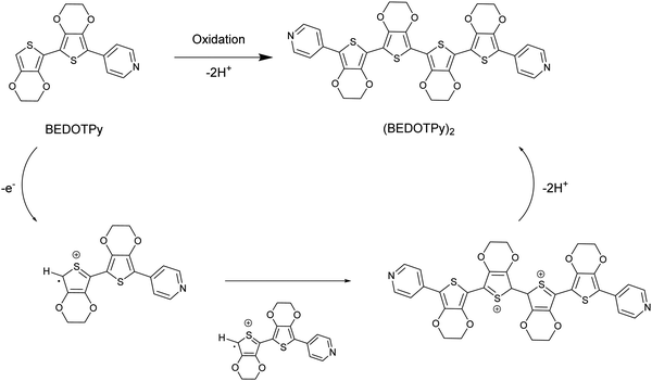
In this paper, we introduce a new class of non-acidic molecular-based material as an alternative to PEDOT:PSS, based on the structure (BEDOTPy)2+˙X− (Scheme 1). This material can be synthesised with a variety of counteranions (X−) and can be quaternised with different side chains on the pyridine. Being molecular-based, it does not suffer some of the problems encountered by polymers, such as batch-to-batch reproducibility which is a well-known problem encountered by those who routinely employ PEDOT:PSS in devices. Herein we report the synthesis, characterisation and application of (BEDOTPy)2+˙ salts, showing that these materials can give improved device stability compared to the analogous device containing PEDOT:PSS as the HTL in an OLED. This demonstration provides an initial proof-of-concept for a molecular-based alternative to PEDOT:PSS and paves the way for a wide range of derivatives based on (BEDOTPy)2+˙X− to be investigated for device applications.
Results and discussion
Synthesis of (BEDOTPy)2+˙X−
The material of interest is the oxidised product of the neutral molecule BEDOTPy, which is shown in Scheme 1. In such a reaction, the removal of an electron from the molecule leads to a radical cation which then dimerises and re-aromatises through the loss of two protons. Oxidative coupling of BEDOTPy has been achieved electrochemically and by chemical oxidation (vide infra). Pyridine itself is an electron deficient unit and unlikely to undergo oxidative coupling.58 However, the attachment of an electron-rich biEDOT unit at the 4-position of the pyridine ring would result in increased electron density in the N-heterocycle and allow the spin density of BEDOTPy radical cation, the resultant of oxidation, to be delocalised through to the pyridine ring. As such, the oxidation of BEDOTPy could result in the generation of a polymer, with connections via radical coupling through the peripheral EDOT unit and the pyridine ring. However, the formation of the dimer (BEDOTPy)2 is much more likely with the radical cation residing predominantly on the terminal EDOT unit, as shown in Scheme 1. Bearing in mind that these statements are assumptions, chemical oxidation of BEDOTPy, even under 1![[thin space (1/6-em)]](https://www.rsc.org/images/entities/char_2009.gif) :
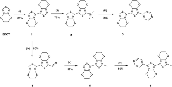
:![[thin space (1/6-em)]](https://www.rsc.org/images/entities/char_2009.gif) 1 stoichiometric conditions, is likely to lead to a doped coupled product which is difficult to characterise by the usual techniques (1H NMR and mass spectrometry). Therefore, the veracity of the structure of the coupled product needed to be verified by other means and to prove irrefutably that there is no coupling through the pyridine ring. We therefore prepared an analogue of BEDOTPy, Me-BEDOTPy, Scheme 2, in which the terminal EDOT was functionalised with a methyl group to block any oxidative coupling reactions through this unit. The synthesis of both compounds and their propensity to couple upon oxidation is discussed in the following two sections.
1 stoichiometric conditions, is likely to lead to a doped coupled product which is difficult to characterise by the usual techniques (1H NMR and mass spectrometry). Therefore, the veracity of the structure of the coupled product needed to be verified by other means and to prove irrefutably that there is no coupling through the pyridine ring. We therefore prepared an analogue of BEDOTPy, Me-BEDOTPy, Scheme 2, in which the terminal EDOT was functionalised with a methyl group to block any oxidative coupling reactions through this unit. The synthesis of both compounds and their propensity to couple upon oxidation is discussed in the following two sections.
Synthesis
The uncapped compound BEDOTPy was synthesised according to Scheme 2. Beginning from 3,4-ethylenedioxythiophene (EDOT), an Ullmann coupling was applied to generate biEDOT (1), by lithiation and coupling with copper(II) chloride (CuCl2). BiEDOT was then stannylated, via lithiation and reaction with trimethyltin chloride, to give the stannyl biEDOT material (2). Compound 2 was then coupled to 4-bromopyridine under Stille conditions to give BEDOTPy (3). The synthesis of the end-capped BEDOTPy, Me-BEDOTPy, was achieved by the formylation of biEDOT to give compound 4, using phosphorus oxychloride and N,N-dimethyl formamide via the Vilsmeier–Haack reaction. The aldehyde functionality was then converted to a methyl group to give compound 5 using hydrazine with potassium hydroxide, via the Wolff–Kishner reduction method. 4-Iodopyridine was then used in a direct arylation, to afford the methyl-capped derivative of BEDOTPy, Me-BEDOTPy (6). The full synthetic procedure and characterisation of all the new compounds can be found in the ESI.†Compound 3 can be further functionalised through the pyridine unit to provide new quaternary materials. As an example, BEDOTPy was reacted (Scheme 3), with 2-iodoethanol by refluxing in acetonitrile to form BEDOTPy-EtOH-I (7). In this example, an ethanol side chain was added for the quaternised pyridine in order to improve solubility in polar solvents. This strategy gives scope for future modification where the side chain can be varied by quaternisation with a range of reagents to modify the solubility, molecular packing or even the energy levels of the material.
Electrochemical study of BEDOTPy, Me-BEDOTPy and BEDOTPy-EtOH-I
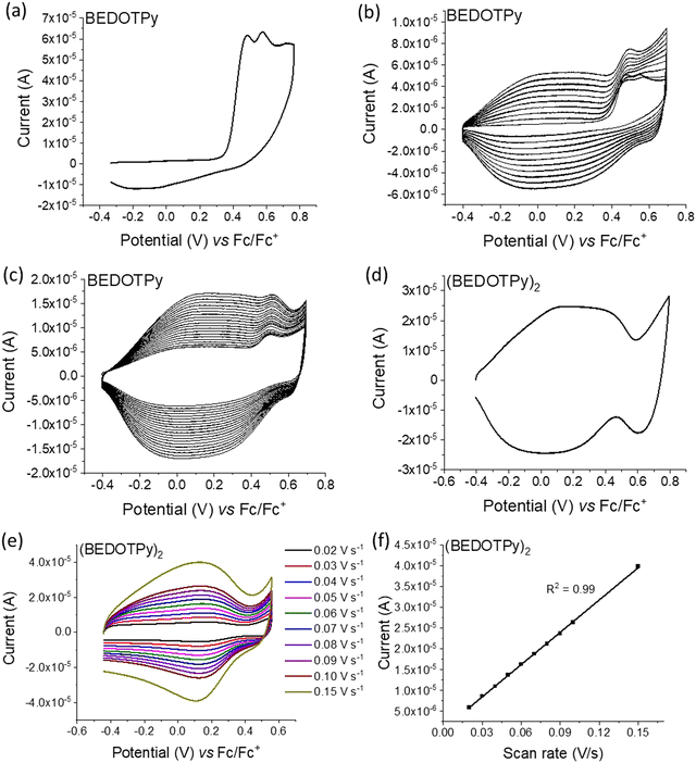
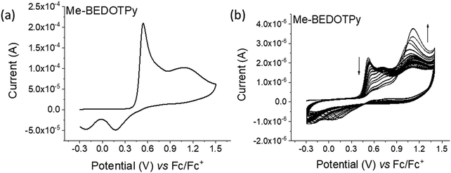
The electrochemical behaviour of the compounds under study was investigated by cyclic voltammetry (CV) and the oxidation of BEDOTPy is shown in Fig. 1(a). The compound displays two irreversible oxidation waves at +0.48 V and +0.58 V, corresponding to the generation of a radical cation and dication, respectively. Upon repetitive cycling over both oxidation waves in the range −0.41 V and +0.70 V, deposition of a product from an electrolytic solution of BEDOTPy was observed visually on the working electrode and its growth can be seen in Fig. 1(b) (0–20 cycles) and Fig. 1(c) (21–60 cycles). A new, broad and reversible oxidation wave is seen to develop upon successive scans, at a lower potential than the oxidation potential of the monomer, which is indicative of the formation of a more electron rich product (i.e. with extended conjugation). Removing the subsequent working electrode from the monomer solution and immersing it in a solution containing solely the electrolyte afforded the CV of the product of oxidation (Fig. 1(d)). This CV shows a broad oxidation wave, which is not dissimilar to that of PEDOT itself, with an onset of −0.44 V and a corresponding estimated HOMO energy of −4.36 eV, referenced to ferrocene. The broad peak indicates the production of a conducting film with a high charge capacity for the material.59,60 The product has a significant decrease in oxidation potential compared to its monomer due to an increase in the conjugation in the backbone. The variance in current maximum of the oxidation peak of the electrogenerated thin film was measured by CV upon increasing the experiment scan rate from 0.02 V s−1 to 0.15 V s−1 (Fig. 1(e)). The anodic current showed a linear increase whilst increasing the scan rate (Fig. 1(f)) with a correlation coefficient r2 = 0.999, confirming that charge transport through the film is not diffusion limited.58,61 These results prove that a new material is formed from the electrochemical oxidation of BEDOTPy, deposited as a film on the working electrode and possessing good stability upon redox cycling, but the data do not confirm whether the product is a dimer or a polymer. This uncertainty is resolved by similar electrochemical studies of Me-BEDOTPy (6).The CV of compound Me-BEDOTPy reveals two irreversible oxidation peaks at +0.44 V and +0.67 V (Fig. 2(a)). The decrease in the current of the first peak upon cycling (Fig. 2(b)) and the lack of the emergence of a peak at lower potentials indicate that not only is there no extension in conjugation, but the most electron rich component of the molecule, the biEDOT unit, is being degraded. It is expected that the methyl group blocks coupling through the thiophene units between cation radical intermediates, and that is proven here, but the results also strongly indicate that there is no coupling and extension of conjugation through the pyridine rings. Therefore, from the electrochemical results, we conclude that oxidation of the compound BEDOTPy results in a dimer and not a polymer. We term this new material (BEDOTPy)2.
The dimerisation of BEDOTPy-ETOH-I was achieved electrochemically by repetitive cycling. In the initial cyclic voltammogram, two irreversible oxidation peaks were observed at +0.54 V and +0.68 V and a quasi-reversible, larger peak at +0.84 V (Fig. S10(a), ESI†). The lower oxidation potential peaks are possibly due to the oxidation of iodide anions (I− and I3−). Upon repetitive cycling over the oxidation window, deposition of a product from a solution of BEDOTPy-ETOH-I was observed and its growth can be seen in Fig. S10(b) (0–20 cycles) and Fig. S10(c) (21–40 cycles) (ESI†). The electrodeposited film of (BEDOTPy-EtOH-I)2 exhibited three reversible oxidation peaks at −0.07 V, +0.39 V, and +0.90 V respectively (Fig. S10(d), ESI†). The variance in current maximum of the oxidation peak of the electrogenerated thin film was measured by CV upon increasing the experiment scan rate from 0.01 V s−1 to 0.15 V s−1 (Fig. S10(e), ESI†). The anodic current showed a linear increase whilst increasing the scan rate (Fig. S10(f), ESI†), with a correlation coefficient r2 = 0.999, confirming that charge transport through the film is not diffusion limited.
Optical studies
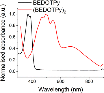
Both the monomer BEDOTPy (0.05 mM solution state in acetonitrile) and (BEDOTPy)2 (thin film deposited on an ITO glass electrode) have been characterised by UV-Vis spectroscopy. As can be seen in Fig. 3, BEDOTPy displays two main peaks at 372 nm and 387 nm, corresponding to the conjugated triaryl unit in the molecule. Extension of the conjugated unit in (BEDOTPy)2 results in a bathochromic shift of these peaks. The spectrum for (BEDOTPy)2 shows fine structure typical of a rigid backbone, as seen for many EDOT-based oligomers and polymers.62 The longest wavelength peak due to a π–π* transition is at 547 nm, and there is a shallow band at lower energy centred at around 670 nm. The latter is ascribed to the doped state of the as-made dimer.Spectroelectrochemistry of (BEDOTPy)2
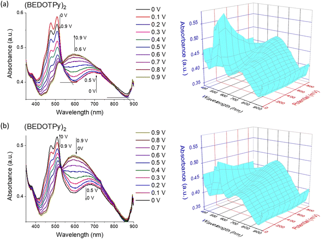
A thin film of (BEDOTPy)2 was electrodeposited on an ITO glass working electrode using potentiodynamic deposition by repeated cycling over the oxidation potential of BEDOTPy in 0.1 M TBAPF6/acetonitrile monomer solution (0.1 mM). Fig. 4 presents the spectroelectrochemistry of (BEDOTPy)2 which was performed in acetonitrile: dichloromethane (3![[thin space (1/6-em)]](https://www.rsc.org/images/entities/char_2009.gif) :
:![[thin space (1/6-em)]](https://www.rsc.org/images/entities/char_2009.gif) 1 v/v) and 0.1 M TBAPF6 as the electrolyte. Applied potential values were increased gradually during the measurement of absorption spectra of the (BEDOTPy)2 thin film. At 0 V, the material is in the doped state with absorbance maxima at around 508 nm (π–π* transition) and a band assigned to the radical cation centred at ca. 700 nm. Raising the potential above 0 V resulted in a decrease in intensity of the bands ascribed to the π–π* transition. From +0.6 V and above, a new broad band emerged, centred at around 600 nm and this is assigned to the attainment of a dication state (Fig. 4(a)). To investigate the electrochromic reversibility of the (BEDOTPy)2 thin film, the potential was decreased back to a neutral state gradually from +0.9 V to 0 V (Fig. 4(b)) with an increase in absorption at 508 nm (λmax of the neutral state). As can be observed from Fig. 4a and b, the spectroelectrochemical plots remain largely unchanged, showing excellent stability of the material through the doping and dedoping processes.
1 v/v) and 0.1 M TBAPF6 as the electrolyte. Applied potential values were increased gradually during the measurement of absorption spectra of the (BEDOTPy)2 thin film. At 0 V, the material is in the doped state with absorbance maxima at around 508 nm (π–π* transition) and a band assigned to the radical cation centred at ca. 700 nm. Raising the potential above 0 V resulted in a decrease in intensity of the bands ascribed to the π–π* transition. From +0.6 V and above, a new broad band emerged, centred at around 600 nm and this is assigned to the attainment of a dication state (Fig. 4(a)). To investigate the electrochromic reversibility of the (BEDOTPy)2 thin film, the potential was decreased back to a neutral state gradually from +0.9 V to 0 V (Fig. 4(b)) with an increase in absorption at 508 nm (λmax of the neutral state). As can be observed from Fig. 4a and b, the spectroelectrochemical plots remain largely unchanged, showing excellent stability of the material through the doping and dedoping processes.
Bulk electrolysis and product analysis
To investigate the properties of the electrogenerated product by larger-scale electrochemical synthesis, oxidative bulk electrolysis was performed at constant potential of 1.1 V. BEDOTPy (40 mg) was dissolved in CH2Cl2 (96 mL) containing TBAPF6 as the electrolyte (3.8 g). At the end of the experiment, a precipitate of the dication salt was isolated with a mass of 78 mg and a yield of 69.8%. The (BEDOTPy)2 product was de-doped chemically using hydrazine monohydrate and then purified by column chromatography. The product was analysed by 1H NMR (Fig. S12, ESI†), electrospray (Fig. S13, ESI†), and MALDI-TOF mass spectrometry (Fig. S14, ESI†). The mass found for the product was 717.09 Da for [M(C34H24N2O8S4) + H]+ which, in addition to the 1H NMR data, indicated the formation of the dimer.Chemical doping and de-doping for BEDOTPy
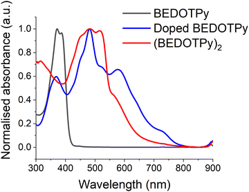
In order to provide further evidence of the veracity of the electrogenerated product, (BEDOTPy)2, chemical doping and de-doping were also performed on the monomer. BEDOTPy was doped chemically using nitrosonium hexafluoroantimonate (NOSbF6). The monomer solution (1 equivalent, 50 mg in 8 mL anhydrous acetonitrile) was mixed under argon atmosphere with NOSbF6 (2.5 equivalent, 90 mg in 8 mL anhydrous acetonitrile) and left under argon to react for 48 hours. The doped solution exhibited an absorption maximum at 482 nm, which is shifted bathochromically compared to the peak at 372 nm for the monomer (Fig. 5). This is due to the increased length of conjugation as discussed previously. The band at ca. 590 nm is a signature of the doped state and, with reference to Fig. 4, is attributed to the dication. The doped mixture was diluted with excess CH2Cl2 to give a blue precipitate which was filtered and collected (30 mg). The solubility of the filtered product was investigated using different solvents (CH2Cl2, chloroform, ethanol, methanol and water). The product was soluble only in acetonitrile. The product was then de-doped by hydrazine monohydrate, forming a red precipitate which itself was soluble only in DMSO. The de-doped product has an absorption spectrum (fine-structured band centred at ca. 482 nm) similar to the spectrum of the electrodeposited film (Fig. S15, ESI†). The difference in λmax absorption between both products is due to their physical state (solution state and solid state), which feature intermolecular interactions in the solid state. The de-doped product was also analysed by 1H NMR spectroscopy (Fig. S16, ESI†) and mass spectrometry (Fig. S17, ESI†) to prove that the obtained product is a dimer (BEDOTPy)2.The optical HOMO–LUMO gap for (BEDOTPy)2 was estimated to be 1.80 eV, taken from the onset of the longest wavelength absorption band of the de-doped material measured in the solution state. The LUMO energy level was estimated from the optical band gap value added to the HOMO value (HOMO + Eg), since no reduction wave was observable by cyclic voltammetry, and it should be noted that this estimation does not take into account the exciton binding energy of the material (Table 1).63
| Product | E ox Onset (V) | HOMO (eV) | LUMO (eV) | λ max (nm) | HOMO–LUMO gap (eV) |
|---|---|---|---|---|---|
| BEDOTPy | +0.35 | −5.15 | −2.18 | 372 | 2.97 |
| (BEDOTPy)2 | −0.44 | −4.36 | −2.56 | 500 | 1.80 |
Solution-processed thin film measurements
In order to explore the conductivity of the doped (BEDOTPy)2 materials, drop-cast and spin-coated films were studied. Nitrosonium salts were used as oxidants due to their efficiency and the fact that the byproduct, nitrogen monoxide, is a gas, resulting in a very clean dimerisation and doping process. It was proposed that slow drying of a high boiling point solvent, DMSO in this case, would assist with creating ordered films which can improve the morphology and conductivity. Solutions were prepared using BEDOTPy and BEDOTPy-EtOH-I (0.8 mg mL−1) with NOSbF6 or NOPF6 (2.5 molar equivalents) with a solvent ratio of 1![[thin space (1/6-em)]](https://www.rsc.org/images/entities/char_2009.gif) :
:![[thin space (1/6-em)]](https://www.rsc.org/images/entities/char_2009.gif) 4 acetonitrile/DMSO. A summary of the conductivity results for these films is shown below in Table 2, whilst examples of current–voltage plots used for the conductivity calculations are shown in Fig. S20 (ESI†).
4 acetonitrile/DMSO. A summary of the conductivity results for these films is shown below in Table 2, whilst examples of current–voltage plots used for the conductivity calculations are shown in Fig. S20 (ESI†).
| Compound/dopant (deposition method) | Average thickness (nm) | Average conductivity (S cm−1) | Standard deviation | Maximum conductivity (S cm−1) |
|---|---|---|---|---|
| a Calculated from an average of 66 devices. b Calculated from an average of 65 devices. c Calculated from an average of 8 devices. d Calculated from an average of 4 devices. | ||||
| BEDOTPy/NOSbF6 (drop-cast) | 183 | 1.06a | 0.87a | 3.75 |
| BEDOTPy-EtOH-I/NOSbF6 (drop-cast) | 149 | 0.13b | 0.29b | 1.85 |
| BEDOTPy-EtOH-I/NOPF6 (drop-cast) | 160 | 0.28c | 0.15c | 0.43 |
| BEDOTPy-EtOH-I/NOPF6 (spin-coated) | 51 | 8.0 × 10⁻⁵d | 1.5 × 10⁻⁴d | 3.1 × 10⁻⁴ |
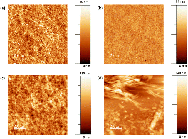
The average electrical conductivity of dimerised BEDOTPy is excellent for a doped organic small molecule, with the maximum measured conductivity reaching 3.75 S cm−1. The slow drying of the films due to using high boiling point solvent, DMSO, in the formulation leads to the formation of well-ordered films, as shown in Fig. 6(a). The topography measurement, carried out using atomic force microscopy, shows many narrow, interconnected domains which are indicative of crystallisation in the film. When BEDOTPy-EtOH-I is dimerised chemically using NOSbF6, there is a drop in conductivity compared to the non-quaternised analogue, which can be explained by disruption of molecular packing from the presence of side chains and/or additional counter ions. However, despite lacking the crystal-like features, the resulting films show good uniformity, with an RMS roughness of 3.0 nm (Fig. 6(b)). When the dopant is changed to NOPF6, the average conductivities are similar but there is a significant difference in the topography (Fig. 6(c)) with there being a large increase in roughness when NOPF6 is used. The solubility of the material dimerised using NOPF6 is not as good, therefore as the film dries, solid may precipitate out more readily to give rougher films.
As well as studying the optimised conductivity of the (BEDOTPy)2 materials, it is important to characterise lower conductivity films that can be used as hole transport layers. The best performing hole transport layer was deposited using 4.5 mg mL−1 BEDOTPy-EtOH-I and showed a low average conductivity of 8.0 × 10⁻⁵ S cm−1. This can be explained by the rough films (Fig. 6(d)) that result from spin-coating the solutions with increased concentration. When compared with flexible polymer chains, it is more difficult to achieve a uniform film with a molecular species. However, the measured conductivity is acceptable for use in hole transport materials and this, along with the ability to process using acetonitrile, makes it possible to construct organic light-emitting diode devices using orthogonal processing.
Water droplet contact angle measurements were carried out on the spin-coated BEDOTPy-EtOH-I film dimerised and doped with NOPF6, as this was most suited for use as a hole transport layer. The images for this and PEDOT:PSS are shown in Fig. S21 (ESI†). The average water droplet contact angle was determined to be 51.8 ± 3.8°. This shows that the layer is hydrophilic in nature but less so than PEDOT:PSS (17.2 ± 1.6°).
In addition to the electrical properties of the films deposited using chemically-doped (BEDOTPy)2 and (BEDOTPy-EtOH-I)2, it is necessary to study the optical properties of the resulting films, as hole transport layers should be transparent to avoid parasitic absorption in OLEDs or OPVs, for example. The transmittance spectra of the films studied for conductivity are shown in Fig. S22 (ESI†).
PEDOT:PSS is highly transparent, with a transmittance ∼95% across the visible region. The drop-cast film of (BEDOTPy)2, doped with NOSbF6 is highly scattering and a reliable transmittance spectrum cannot be obtained. Drop-cast films of NOPF6-doped (BEDOTPy-EtOH-I)2 show a lowest transmittance of 66% at 385 nm, which suggests the presence of undoped BEDOTPy-EtOH-I in the deposited film. When NOSbF6 is used instead there appears to be improved doping as the maximum absorbance is at 536 nm, and is more intense than the peak corresponding to BEDOTPy-EtOH-I. The transmittance is greatly improved when using NOSbF6 with a minimum transmittance in the visible region of 81%. This is caused by the greater size of the SbF6− counter ions, which can suppress the formation of aggregates and their absorption. This is supported by the AFM images as the NOSbF6-doped film (Fig. 6a) shows narrower aggregates compared to the NOPF6-doped film (Fig. 6c).
The spin-coated film of NOPF6-doped (BEDOTPy-EtOH-I)2 was also studied. In the visible region, the lowest transmittance is 77% at 380 nm. There is also a peak at 600 nm (81% transmittance), which corresponds to the doped state of (BEDOTPy-EtOH-I)2. There is significant absorption of doped (BEDOTPy)2 and (BEDOTPy-EtOH-I)2 in the visible region which makes it difficult to achieve a transmittance similar to PEDOT:PSS, which is more strongly absorbing in the near-IR region. However, a transmittance at greater than 77% across the visible region is sufficient to create functioning OLED devices and determine if the lack of acidity can allow improved stability.
Organic light-emitting diode (OLED) lifetime studies
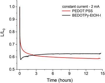
In order to assess the applicability of dimerised BEDOTPy materials as hole transport layers (HTLs), organic light-emitting diodes were fabricated with BEDOTPy-EtOH-I and compared with PEDOT:PSS. The quaternised material, BEDOTPy-EtOH-I, was chosen for these studies due to its improved solubility in acetonitrile, which is necessary for solutions prepared at a higher concentration to be used for spin-coating. The hole transport layer was prepared by using BEDOTPy-EtOH-I at a concentration of 4.5 mg mL−1 in acetonitrile, with 2.5 molar equivalents of nitrosonium hexafluorophosphate added to cause dimerisation and doping of the material. The average thickness for this layer was determined to be 51 nm.A simple device structure of ITO/HTL/Super Yellow/Ca/Al was chosen to assist with understanding the role of the hole transport layer in the degradation of the OLED over time. For example, a fluorescent emissive layer was specifically chosen instead of a material that exhibits thermally activated delayed fluorescence (TADF) due to the excellent stability of fluorescent emitters. The characteristics of the tested OLEDs are summarised in Table S1 and Fig. S23 (ESI†), with repeat devices shown in Fig. S24 (ESI†). The device containing dimerised BEDOTPy-EtOH-I shows competitive performance when compared with a reference device containing PEDOT:PSS, albeit the current efficiency and maximum luminance are lower. This may be explained by the increased absorbance of the dimerised BEDOTPy-EtOH-I layer when compared with PEDOT:PSS. The lifetime of the OLEDs, held at a constant current (2 mA), in a nitrogen atmosphere, was compared to determine whether the omission of PSS could lead to improved device lifetime in dimerised BEDOTPy-EtOH-I layers. These plots are shown in Fig. 7.
There are significant burn-in processes for both devices which causes a drop in luminance but this is more marked in the device containing the treated BEDOTPy-EtOH-I dimer. This may be caused by a Joule heating effect which affects the polymer ordering as Super Yellow has a glass transition temperature of ∼83 °C.64 This effect is likely to be larger for BEDOTPy-EtOH-I dimer devices, which requires a higher voltage (5.40 V) to measure 2 mA compared to the analogous PEDOT:PSS-containing device (3.95 V). However, despite the higher power applied in oxidised and dimerised BEDOTPy-EtOH-I based devices, the luminance then slightly increases and stabilises, showing negligible degradation. On the other hand, the PEDOT:PSS-containing device shows a gradual decrease in luminance over time, with the oxidised BEDOTPy-EtOH-I dimer layer showing a higher ratio of luminance/initial luminance (L/L0) value after only three hours. The stability of the OLED containing BEDOTPy-EtOH-I can be considered more impressive when comparing relative performance after the burn-in – there is no evidence of further degradation. This is not the case for the PEDOT:PSS containing device, indicating a poorer device stability when this hole transport layer is used.
Conclusions
A new class of non-acidic, molecular materials based on the structure (BEDOTPy)2+˙X− has been introduced as an alternative to PEDOT:PSS. This material is formed from an oxidative coupling of the pyridine-capped biEDOT monomer, BEDOTPy, which has large scope for modification by quaternisation or use of different counter ions. Studies of the methyl-capped Me-BEDOTPy proved that the dimer is formed rather than any polymerisation, bonding through the pyridine for example. The oxidised, quaternised dimer has a maximum conductivity > 1 S cm−1 and an average conductivity of > 0.1 S cm−1 when drop-cast and can be used as a hole transport layer in OLEDs, giving longer device lifetime in an OLED with a Super Yellow emissive layer. The molecular structure of BEDOTPy gives it scope to be modified to tune the ionisation energy or solubility in different solvents for example, something that cannot be easily achieved for PEDOT:PSS. We anticipate that this hole transport layer will be applicable to organic photovoltaics as well as OLEDs, especially if the transmittance is further optimised. As a result, this type of material can be considered a promising alternative to PEDOT:PSS and alleviates the acid-induced degradation and batch-to-batch variation which are common problems with the widely used PEDOT:PSS.Conflicts of interest
There are no conflicts of interest to declare.Acknowledgements
The authors thank EPSRC for funding through grants EP/T022477/1 and EP/R03480X/1. Supporting raw data for the manuscript can be accessed at the following address: http://dx.doi.org/10.5525/gla.researchdata.1492.References
- J. C. Scott, S. A. Carter, S. Karg and M. Angelopoulos, Synth. Met., 1997, 85, 1197–1200 CrossRef CAS
.
- Y. Cui, H. Yao, J. Zhang, K. Xian, T. Zhang, L. Hong, Y. Wang, Y. Xu, K. Ma, C. An, C. He, Z. Wei, F. Gao and J. Hou, Adv. Mater., 2020, 32, 1908205 CrossRef CAS PubMed
.
- Y. Xia and S. Dai, J. Mater. Sci.: Mater. Electron., 2021, 32, 12746–12757 CrossRef CAS
.
- A. Salehi, X. Fu, D.-H. Shin and F. So, Adv. Funct. Mater., 2019, 29, 1808803 CrossRef
.
- J. Cameron and P. J. Skabara, Mater. Horiz., 2020, 7, 1759–1772 RSC
.
- M. P. D. Jong, L. J. V. IJzendoorn and M. Voigt, Appl. Phys. Lett., 2000, 77, 2255–2257 CrossRef
.
- K. W. Wong, H. L. Yip, Y. Luo, K. Y. Wong, W. M. Lau, K. H. Low, H. F. Chow, Z. Q. Gao, W. L. Yeung and C. C. Chang, Appl. Phys. Lett., 2002, 80, 2788–2790 CrossRef CAS
.
- D. Akın Kara, K. Kara, G. Oylumluoglu, M. Z. Yigit, M. Can, J. J. Kim, E. K. Burnett, D. L. Gonzalez Arellano, S. Buyukcelebi, F. Ozel, O. Usluer, A. L. Briseno and M. Kus, ACS Appl. Mater. Interfaces, 2018, 10, 30000–30007 CrossRef PubMed
.
- S. H. Choi, S. M. Jeong, W. H. Koo, S. J. Jo, H. K. Baik, S.-J. Lee, K. M. Song and D. W. Han, Thin Solid Films, 2005, 483, 351–357 CrossRef CAS
.
- S. Rafique, S. M. Abdullah, M. M. Shahid, M. O. Ansari and K. Sulaiman, Sci. Rep., 2017, 7, 39555 CrossRef CAS PubMed
.
- W. Kim, J. Kyu Kim, Y. Lim, I. Park, Y. Suk Choi and J. Hyeok Park, Sol. Energy Mater., 2014, 122, 24–30 CrossRef CAS
.
- X. Jiang, Y. Ma, Y. Tian, A. Wang, A. Wang, S. Zhang, S. Wang and Z. Du, Org. Electron., 2020, 78, 105589 CrossRef CAS
.
- Y. Mochizuki, T. Horii and H. Okuzaki, Trans. Mater. Res. Soc. Jpn., 2012, 37, 307–310 CrossRef CAS
.
- M. De Kok, M. Buechel, S. Vulto, P. van de Weijer, E. Meulenkamp, S. De Winter, A. Mank and H. Vorstenbosch, Phys. Status Solidi A, 2004, 201, 1342–1359 CrossRef CAS
.
- H. Kim, S. Nam, H. Lee, S. Woo, C.-S. Ha, M. Ree and Y. Kim, J. Phys. Chem. C, 2011, 115, 13502–13510 CrossRef CAS
.
- S. Chen, L. Song, Z. Tao, X. Shao, Y. Huang, Q. Cui and X. Guo, Org. Electron., 2014, 15, 3654–3659 CrossRef CAS
.
- S. Kim, S. Y. Kim, M. H. Chung, J. Kim and J. H. Kim, J. Mater. Chem. C, 2015, 3, 5859–5868 RSC
.
- S. Shao, J. Liu, J. Bergqvist, S. Shi, C. Veit, U. Würfel, Z. Xie and F. Zhang, Adv. Energy Mater., 2013, 3, 349–355 CrossRef CAS
.
- D. J. D. Moet, P. D. Bruyn and P. W. M. Blom, Appl. Phys. Lett., 2010, 96, 153504 CrossRef
.
- D. N. Nguyen, S. H. Roh, D.-H. Kim, J. Y. Lee, D. H. Wang and J. K. Kim, Dyes Pigm., 2021, 194, 109610 CrossRef CAS
.
- A. I. Hofmann, W. T. Smaal, M. Mumtaz, D. Katsigiannopoulos, C. Brochon, F. Schütze, O. R. Hild, E. Cloutet and G. Hadziioannou, Angew. Chem., 2015, 127, 8626–8630 CrossRef
.
- A. I. Hofmann, D. Katsigiannopoulos, M. Mumtaz, I. Petsagkourakis, G. Pecastaings, G. Fleury, C. Schatz, E. Pavlopoulou, C. Brochon and G. Hadziioannou, Macromolecules, 2017, 50, 1959–1969 CrossRef CAS
.
- Y. Jiang, X. Dong, L. Sun, T. Liu, F. Qin, C. Xie, P. Jiang, L. Hu, X. Lu, X. Zhou, W. Meng, N. Li, C. J. Brabec and Y. Zhou, Nat. Energy, 2022, 7, 352–359 CrossRef CAS
.
- H. Meng, D. F. Perepichka and F. Wudl, Angew. Chem., Int. Ed., 2003, 42, 658–661 CrossRef CAS PubMed
.
- J. P. Lock, S. G. Im and K. K. Gleason, Macromolecules, 2006, 39, 5326–5329 CrossRef CAS
.
- R. Bhargav, D. Bhardwaj, Shahjad, A. Patra and S. Chand, ChemistrySelect, 2016, 1, 1347–1352 CrossRef CAS
.
- M. N. Gueye, A. Carella, N. Massonnet, E. Yvenou, S. Brenet, J. Faure-Vincent, S. Pouget, F. Rieutord, H. Okuno, A. Benayad, R. Demadrille and J.-P. Simonato, Chem. Mater., 2016, 28, 3462–3468 CrossRef CAS
.
- K. M. Reza, A. Gurung, B. Bahrami, S. Mabrouk, H. Elbohy, R. Pathak, K. Chen, A. H. Chowdhury, M. T. Rahman, S. Letourneau, H.-C. Yang, G. Saianand, J. W. Elam, S. B. Darling and Q. Qiao, J. Energy Chem., 2020, 44, 41–50 CrossRef
.
- K. C. Kwon, C. Kim, Q. V. Le, S. Gim, J.-M. Jeon, J. Y. Ham, J.-L. Lee, H. W. Jang and S. Y. Kim, ACS Nano, 2015, 9, 4146–4155 CrossRef CAS PubMed
.
- P. Huang, Z. Wang, Y. Liu, K. Zhang, L. Yuan, Y. Zhou, B. Song and Y. Li, ACS Appl. Mater. Interfaces, 2017, 9, 25323–25331 CrossRef CAS PubMed
.
- K. Zilberberg, S. Trost, H. Schmidt and T. Riedl, Adv. Energy Mater., 2011, 1, 377–381 CrossRef CAS
.
- C. Girotto, E. Voroshazi, D. Cheyns, P. Heremans and B. P. Rand, ACS Appl. Mater. Interfaces, 2011, 3, 3244–3247 CrossRef CAS PubMed
.
- A. Soultati, A. M. Douvas, D. G. Georgiadou, L. C. Palilis, T. Bein, J. M. Feckl, S. Gardelis, M. Fakis, S. Kennou, P. Falaras, T. Stergiopoulos, N. A. Stathopoulos, D. Davazoglou, P. Argitis and M. Vasilopoulou, Adv. Energy Mater., 2014, 4, 1300896 CrossRef
.
- C. Zheng, F. Li, Q. Zeng, H. Hu and T. Guo, Thin Solid Films, 2019, 669, 387–391 CrossRef CAS
.
- H. Choi, B. Kim, M. J. Ko, D.-K. Lee, H. Kim, S. H. Kim and K. Kim, Org. Electron., 2012, 13, 959–968 CrossRef CAS
.
- Z. a Tan, L. Li, C. Cui, Y. Ding, Q. Xu, S. Li, D. Qian and Y. Li, J. Phys. Chem. C, 2012, 116, 18626–18632 CrossRef CAS
.
- K. X. Steirer, P. F. Ndione, N. E. Widjonarko, M. T. Lloyd, J. Meyer, E. L. Ratcliff, A. Kahn, N. R. Armstrong, C. J. Curtis, D. S. Ginley, J. J. Berry and D. C. Olson, Adv. Energy Mater., 2011, 1, 813–820 CrossRef CAS
.
- J. R. Manders, S.-W. Tsang, M. J. Hartel, T.-H. Lai, S. Chen, C. M. Amb, J. R. Reynolds and F. So, Adv. Funct. Mater., 2013, 23, 2993–3001 CrossRef CAS
.
- F. Jiang, W. C. H. Choy, X. Li, D. Zhang and J. Cheng, Adv. Mater., 2015, 27, 2930–2937 CrossRef CAS PubMed
.
- S.-S. Li, K.-H. Tu, C.-C. Lin, C.-W. Chen and M. Chhowalla, ACS Nano, 2010, 4, 3169–3174 CrossRef CAS PubMed
.
- I. P. Murray, S. J. Lou, L. J. Cote, S. Loser, C. J. Kadleck, T. Xu, J. M. Szarko, B. S. Rolczynski, J. E. Johns, J. Huang, L. Yu, L. X. Chen, T. J. Marks and M. C. Hersam, J. Phys. Chem. Lett., 2011, 2, 3006–3012 CrossRef CAS
.
- J. Kim, A. K. Sarker, Y. Park, J. Kwak, H.-J. Song and C. Lee, RSC Adv., 2021, 11, 27199–27206 RSC
.
- N. Yaacobi-Gross, N. D. Treat, P. Pattanasattayavong, H. Faber, A. K. Perumal, N. Stingelin, D. D. C. Bradley, P. N. Stavrinou, M. Heeney and T. D. Anthopoulos, Adv. Energy Mater., 2015, 5, 1401529 CrossRef
.
- A. Perumal, H. Faber, N. Yaacobi-Gross, P. Pattanasattayavong, C. Burgess, S. Jha, M. A. McLachlan, P. N. Stavrinou, T. D. Anthopoulos and D. D. C. Bradley, Adv. Mater., 2015, 27, 93–100 CrossRef CAS PubMed
.
- T. Ding, N. Wang, C. Wang, X. Wu, W. Liu, Q. Zhang, W. Fan and X. W. Sun, RSC Adv., 2017, 7, 26322–26327 RSC
.
- W.-D. Hu, C. Dall’Agnese, X.-F. Wang, G. Chen, M.-Z. Li, J.-X. Song, Y.-J. Wei and T. Miyasaka, J. Photochem. Photobiol., A, 2018, 357, 36–40 CrossRef CAS
.
- H. Javaid, N. Heller, V. V. Duzhko, N. Hight-Huf, M. D. Barnes and D. Venkataraman, ACS Appl. Energy Mater., 2022, 5, 8075–8083 CrossRef CAS
.
- J. Yu, X. Liu, Z. Zhong, C. Yan, H. Liu, P. W. K. Fong, Q. Liang, X. Lu and G. Li, Nano Energy, 2022, 94, 106923 CrossRef CAS
.
- P. Worakajit, T. Sudyoadsuk, V. Promarak, A. Saeki and P. Pattanasattayavong, J. Mater. Chem. C, 2021, 9, 10435–10442 RSC
.
- H. Kim, J. W. Lee, G. R. Han, Y. J. Kim, S. H. Kim, S. K. Kim, S. K. Kwak and J. H. Oh, Adv. Funct. Mater., 2022, 32, 2110069 CrossRef CAS
.
- H. Zhou, Y. Zhang, C.-K. Mai, S. D. Collins, T.-Q. Nguyen, G. C. Bazan and A. J. Heeger, Adv. Mater., 2014, 26, 780–785 CrossRef CAS PubMed
.
- H. Choi, C.-K. Mai, H.-B. Kim, J. Jeong, S. Song, G. C. Bazan, J. Y. Kim and A. J. Heeger, Nat. Commun., 2015, 6, 1–6 CAS
.
- P. Lagonegro, C. Martella, B. M. Squeo, F. Carulli, G. Scavia, A. Lamperti, F. Galeotti, B. Dubertret, M. Pasini, S. Brovelli, A. Molle and U. Giovanella, ACS Appl. Electron. Mater., 2020, 2, 1186–1192 CrossRef CAS
.
- Z. Zhang, J. Liang, Y. Zheng, X. Wu, J. Wang, Y. Huang, Y. Yang, Z. Zhou, L. Wang and L. Kong, J. Mater. Chem. A, 2021, 9, 17830–17840 RSC
.
- Y. Lim, Y.-S. Park, Y. Kang, D. Y. Jang, J. H. Kim, J.-J. Kim, A. Sellinger and D. Y. Yoon, J. Am. Chem. Soc., 2011, 133, 1375–1382 CrossRef CAS PubMed
.
- H.-W. Lin, W.-C. Lin, J.-H. Chang and C.-I. Wu, Org. Electron., 2013, 14, 1204–1210 CrossRef CAS
.
- L. Liu, S. Li, L. Wu, D. Chen, K. Cao, Y. Duan and S. Chen, Org. Electron., 2021, 89, 106047 CrossRef CAS
.
-
T. Otsubo and K. Takimiya, Handbook of Thiophene-Based Materials, 2009, pp. 321–340 DOI:10.1002/9780470745533.ch6
.
-
J. R. Reynolds, B. C. Thompson and T. A. Skotheim, Conjugated Polymers: Properties, Processing, and Applications, CRC press, 2019 Search PubMed
.
- J. Roncali, Chem. Rev., 1992, 92, 711–738 CrossRef CAS
.
- Y. Wei, C. C. Chan, J. Tian, G. W. Jang and K. F. Hsueh, Chem. Mater., 1991, 3, 888–897 CrossRef CAS
.
- H. J. Spencer, P. J. Skabara, M. Giles, I. McCulloch, S. J. Coles and M. B. Hursthouse, J. Mater. Chem., 2005, 15, 4783–4792 RSC
.
- J.-L. Bredas, Mater. Horiz., 2014, 1, 17–19 RSC
.
- S. Burns, J. MacLeod, T. Trang Do, P. Sonar and S. D. Yambem, Sci. Rep., 2017, 7, 40805 CrossRef CAS PubMed
.
Footnote |
| † Electronic supplementary information (ESI) available. See DOI: https://doi.org/10.1039/d3mh01060k |
| This journal is © The Royal Society of Chemistry 2023 |


