
 Open Access Article
 This Open Access Article is licensed under a Creative Commons Attribution-Non Commercial 3.0 Unported Licence
Advances in the ratiometric combination of quantum dots for their use in sensing applications
Sumon
Santra
 *a,
Sourav
Dutta
b and
Ashadul
Adalder
*a
*a,
Sourav
Dutta
b and
Ashadul
Adalder
*a
aDepartment of Industrial Chemistry, Ramakrishna Mission Vidyamandira, Belur Math, Howrah-711202, India. E-mail: iamashadul@gmail.com; sumonsantra205@gmail.com
bDepartment of Chemistry, University of Calcutta, Kolkata-700009, India
First published on 8th August 2023
Abstract
Quantum dots (QDs) are a novel nanomaterial and have long piqued scientific curiosity. As a result of their nanoscale size, they exhibit a variety of chemical and physical characteristics. They are low-cost materials having good photoluminescence properties and rich surface functional groups. The use of quantum dots as a visual sensor is widely studied. Here, in this review, we summarize some commonly used quantum dots in sensing applications and how they can be used in ratiometric combinations to achieve a higher limit of detection (LOD). From metal ions to biomolecules and from explosives to organic quantum dots have been used widely as a sensor. In the later sections, some basic sensing mechanisms were also discussed. Finally, we suggest future prospects for how quantum dots could be industrially upscaled and be used to create sensor devices for use as field test kits.
 Sumon Santra | Sumon Santra did his BSc in Industrial Chemistry from Ramakrishna Mission Vidyamandira College, Calcutta University, India, and is currently pursuing his MSc degree in Applied Chemistry in the same department. He has worked in the field of material science, mainly on Quantum Dots and Graphene. His current research interest is energy harvesting and storage applications. |
 Sourav Dutta | Sourav Dutta received his MSc degree at the Department of Chemistry, Jadavpur University, Kolkata, India, in 2017. Then, he was admitted to pursue his PhD degree at the University of Calcutta under the supervision of Professor Debabrata Mandal. He submitted his PhD thesis in February 2023. His research focuses on the synthesis, characterization, and spectroscopic studies of some novel ESIPT fluorophores in different media such as solvents, micelles, reverse micelles, and hydrogels. |
 Ashadul Adalder | Ashadul Adalder received his Master's Degree (MSc) in Applied Chemistry from Ramakrishna Mission Vidyamandira, Calcutta University in 2018. Then, he graduated from IIT Bombay in 2020 with an MTech degree in Metallurgical Engineering and Materials Science. He is currently working as a senior researcher in Dr Uttam Kumar Ghorai's group. His research focuses on electrochemical N2/CO2/NO3−/NO2−/NO fixation to value-added products and energy storage applications. |
1. Introduction
The world is constantly being enlightened by research in the field of nanotechnology. Quantum dots (QDs) are one of the vast topics that include the applications of zero-dimensional nanomaterials. These materials are smaller with dimensions less than 100 nm in size.1 Due to their small size, high surface-to-volume ratios, and quantum confinement effect, they are widely used in various applications. From the application of energy storage2 to pollution remediation,3 from biomedical4 to aerospace5 applications, they have proved themselves useful. Due to the quantum confinement effects, these materials possess photoluminescence properties. One such class of nanoscale material is quantum dots. Due to their optical properties, quantum dots have gained use in various sensing applications.6 With the change in the size, shape, dopants, and functional groups, the fluorescence properties of these nanomaterials change.7 The color of the fluorescence is mainly due to the change in size and functional groups. Smaller quantum dots generally have bluish-to-green emission, and as the size increases, the emission wavelength gets red-shifted.7 This red-shifting nature can be again explained due to the quantum confinement effect. Another factor is the presence of fluorophore contents and solvent effect, which also affects the emission.8 By utilizing the fluorescence property of these materials, scientists have worked on various materials to prepare different types of quantum dots and further used them for sensing applications.With the advancement in the industrial sectors, there has been an increased rate of environmental pollution. Nowadays, water pollution due to several contaminants is a rising concern. There are hundreds of papers on the synthesis of quantum dots from different precursors. This includes reagent-grade materials,9,10 waste materials,11,12 and natural precursors.13,14 When speaking of its applications, QDs have been widely used in the detection of different chemical species. There are different and multiple uses of quantum dots in the detection of different substances in the water medium. QDs can be prepared from different source materials and can be classified as carbon QDs,15–18 TMD QDs,19,20 polymeric QDs,21 graphene QDs,14,22–25 perovskite QDs,26,27etc. All categories of these materials have shown excellent properties in different fields of material science. In the early stages, the metal-based QDs had served as an excellent material. After the advent of carbon-based QDs, CQDs were preferred for their low synthesis cost, better size and fluorescence tunability, photostability, and biocompatibility. Other than sensing applications, they have also been used in various pH and fluorescent indicators and as fluorescent ink.28 The most prominent feature of fluorescence from CQDs is the tunable emission wavelength and intensity, which may originate from the broad size distribution, different surface defects, different surface states or degrees of π conjugation, and so on.7 There are thousands of works on QDs and their application in sensing applications. However, there has not been much commercial use of those sensor materials in the market.
There have been several efforts to replace metal-based semiconductor QDs with carbon-based QDs having similar properties. One of the extraordinary advantages of using carbon-based QDs is that they can be derived from natural precursors and used for the same purpose. One of the classes of carbon-based QDs is the graphene quantum dots (GQDs), and they can be easily identified from their characteristic TEM images having localized lattice fringes.29 They have been shown to have a high tunable fluorescence range with higher quantum yield. Also, in recent years, ordinary carbon QDs have also been shown to have an extremely high quantum yield (QY) greater than around 70%.30,31
Herein, we summarize the current research trend of using these fluorescent sensors in a ratiometric combination and their possibility in industrial upscaling. It is expected that if optimized and upscaled and used in ratiometric combinations, this material could be commercialized as a field test kit for contaminants. As in ratiometric combinations with complementary colored inert fluorescent material, this can be a good naked-eye visual test kit. A possible model for the field test kit having multiple sensing probes is represented in Fig. 1.
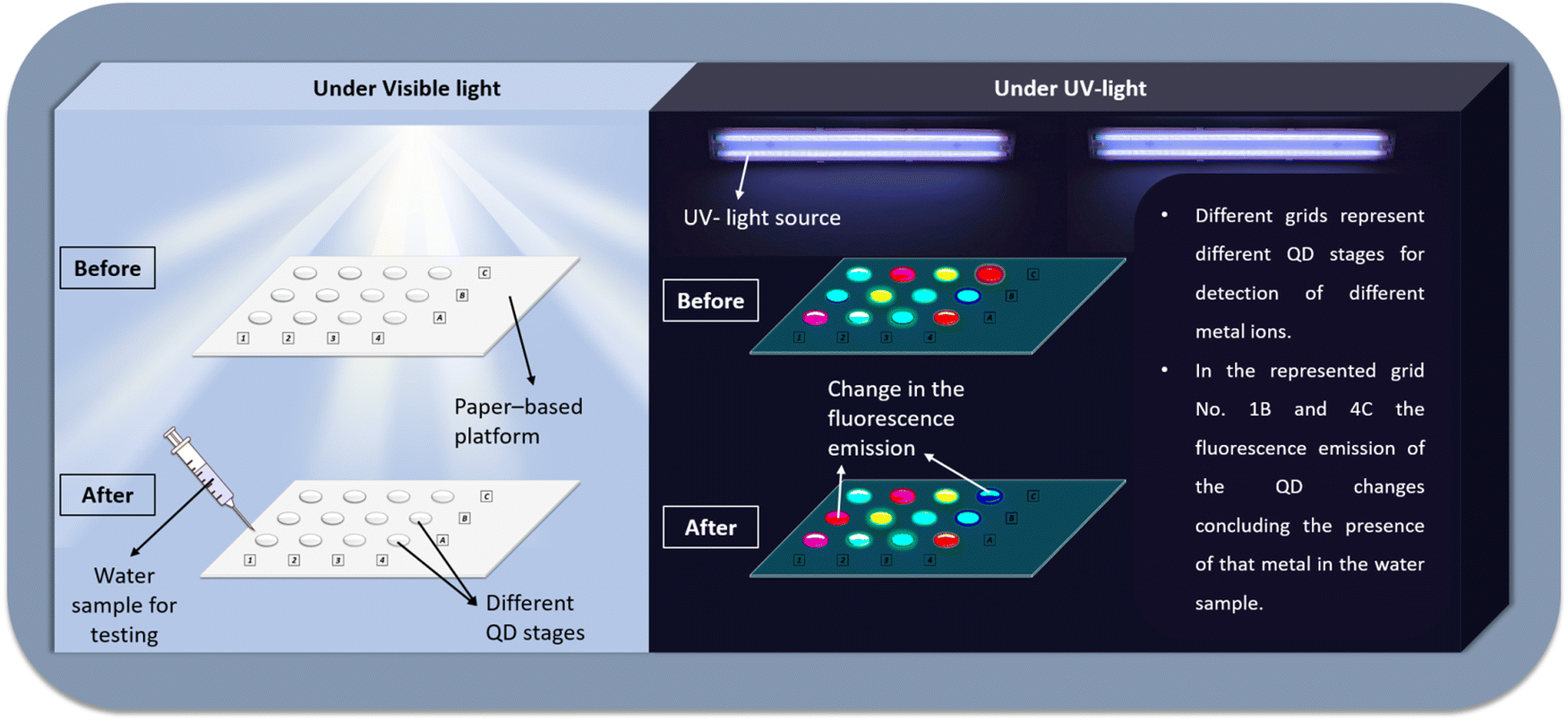 | ||
| Fig. 1 A model representing a possible paper-based ratiometric test kit with multiple different QD channels for the detection of multiple compounds/ions in a single assay. | ||
2. Different types of quantum dots used in sensing applications
Some commonly used quantum dots which are widely used in fluorometric sensing applications include graphene quantum dots, carbon quantum dots, and cadmium telluride quantum dots. Over the last two decades, several modifications in the synthesis pathway have been adapted to create modified systems for getting good LOD for a particular analyte. It was in 2004 when CQDs were accidentally prepared by Xu et al. from single-walled carbon nanotubes.32 The chemical structure of CQDs is mainly composed of sp2 and sp3 carbon7 and surface functional groups of oxygen and nitrogen,7 polymeric structures,7 or could be any other doped elements.33–35 Under analysis by XRD, CQDs give rise to a broad peak between the 2θ value of 21–26°, which is due to the (002) plane.36 The fluorescence and absorbance spectra of CQDs have comparable optical behavior when it comes to their optical features. Following UV stimulation, they often exhibit robust emission in the visible spectrum, including high UV absorption and an extended visible spectrum tail. The π–π* and n–π* transitions, resulting from changes in the aromatic C–C bond and C![[double bond, length as m-dash]](https://www.rsc.org/images/entities/char_e001.gif) O bond, respectively, are the most often seen transitions.37 Carbon quantum dots can often have clear crystallization. Unlike the inorganic QDs, where the fluorescence property of the QDs is totally dependent on the size factor, in the case of CQDs, the fluorescence property is governed by both the size factor as well as the surface functional groups.38,39
O bond, respectively, are the most often seen transitions.37 Carbon quantum dots can often have clear crystallization. Unlike the inorganic QDs, where the fluorescence property of the QDs is totally dependent on the size factor, in the case of CQDs, the fluorescence property is governed by both the size factor as well as the surface functional groups.38,39
Another important category of carbon-based quantum dots is graphene quantum dots (GQD). The primary difference between CQDs and GQDs is that CQDs are prepared from carbon sources where they do not have regular shape arrangements, whereas GQDs have carbon atoms orderly arranged in a hexagonal lattice system. The structure of GQDs is similar to that of graphene and looks like its small fragments, with exceptional luminescence properties.40 GQDs are one of the significant types of carbon-based nanoparticles widely used in sensing applications. Fig. 2c shows the structure of GQDs.7 They generally have a size of lesser than 10 nm, and in most cases, the layer of GQDs is not more than 5 layers.41 GQDs may be made from a variety of materials, including graphene oxide,42 citric acid,43 glucose,24etc. Similar to semiconductor quantum dots, GQDs are famous for having intense blue-to-green fluorescence. The GQDs are often known to contain a large amount of functional group-rich surface and are also in crystalline form.44 The functional groups that are mainly present in the GQDs are carboxyl, hydroxyl, and carbonyl groups. These functional groups of GQDs have been previously reported to detect some metal ions like iron.45 It could be possible to utilize them in sensing applications. Unlike that of graphene, which has a zero band-gap, in GQD, the band-gap can be tunable, expanding its scope in applications like optoelectronic and photonics. From the characterization perspective, the band-gap of GQDs can be easily calculated by the Tauc plot from the graph obtained from the UV spectra. One very good advantage of GQDs is that their edge can be easily functionalized according to desired requirements and thus making it an appropriate nanomaterial for sensing applications.46
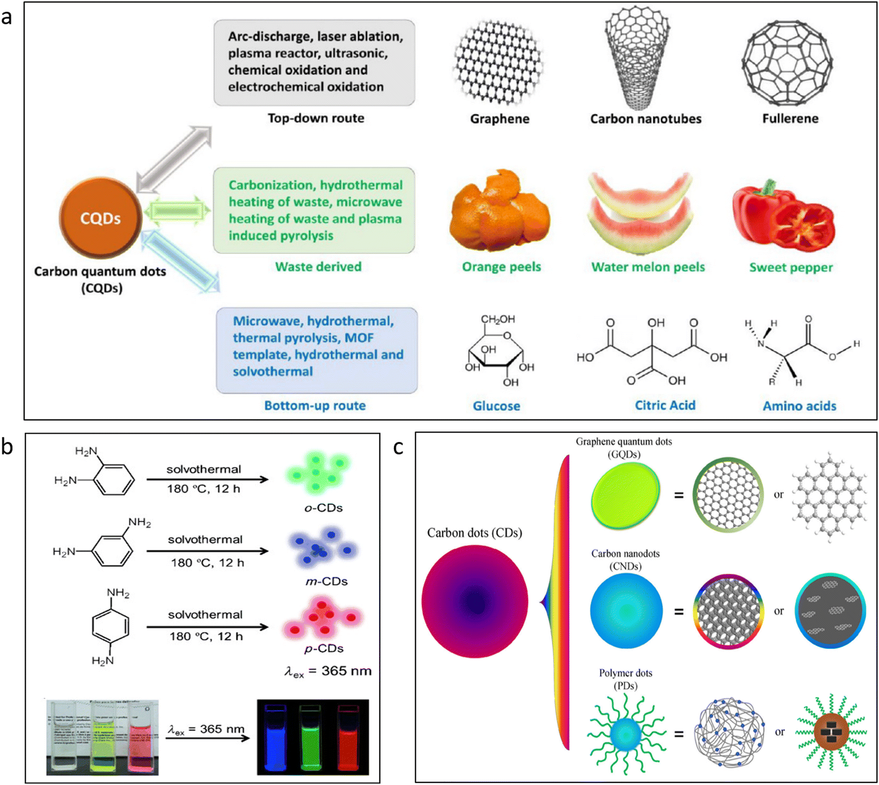 | ||
| Fig. 2 (a) Different sources for the synthesis of carbon quantum dots.76 Adapted with permission from ref. 76. Copyright 2021 American Chemical Society. (b) Different fluorescent emissions of carbon dots from similar chemical precursors.73 Adapted with permission from ref. 73. Copyright 2015. Wiley-VCH. (c) Different grades of carbon dots, including crystalline graphene quantum dots and polymeric dots.7 Adapted with permission from ref. 7. Copyright 2014. Springer Nature. | ||
Of these three quantum dots, cadmium telluride quantum dots have been quite popular in sensing and bioimaging applications. It is one such example of inorganic quantum dots. Similar to that of the CdTe crystal, which forms a regular FCC system, CdTe QDs are also crystalline in nature. The crystalline domains of CdTe QDs can be clearly observed in HR-TEM images. The XRD spectra of CdTe QDs show the prominent peaks of (111), (220), and (311).9 One of the most interesting features of CdTe QDs is their optical properties. Due to the quantum confinement effect, the fluorescence emission of the CdTe QDs is dependent on its size. With the increase in the size of the CdTe QDs, the fluorescence emission of the QDs gets red-shifted. This property of the nanomaterials gives users a wide scope of optimization for getting desired fluorescence systems. Simple tuning in the synthesis procedure could lead to different color emissions of the QDs.
3. Preparation of different types of quantum dots
Top-down and bottom-up processes are typically separated into two groups whenever we discuss the synthesis of a nanomaterial. Numerous strategies are likewise relevant in this situation for the synthesis of QDs. This covers top-down synthesis techniques such as laser ablation,47 arc-discharge,48 electrochemical,49,50 ultrasonic assistance,51 and chemical exfoliation.52 Techniques like microwave synthesis,53,54 thermal pyrolysis,55 hydrothermal,56,57 and solvothermal routes,58 the bottom-up approaches also incorporate them. However, in actual application, some of these methods are not preferred in specific sectors because of various difficulties and the high cost of synthesis. An attempt should be made to make these QDs for the manufacture of a sensor material in the most cost-effective manner possible, such as by the use of ultrasonic techniques, solvothermal and hydrothermal processes, microwave synthesis, etc. Additionally, efforts should be made to synthesize these materials on a kilogram scale.59 Baragau et al.57 reported the synthesis of CQDs from readily available biomass precursors. In this upscaling method, continuous hydrothermal flow synthesis was used with supercritical water. This method was fast, efficient, and continuous, which could be industrially upscaled for the large batch synthesis of these nanomaterials.CQDs, GQDs, and CdTe QDs are frequently employed for sensing applications. These materials were chosen because of their variety of unique properties, including simplicity in synthesis,16,60–62 good size tunability,17 and high fluorescence quantum yield.63–65 Some of the typical procedures for the synthesis of CQDs are shown in Fig. 2a. The top-down synthesis from the bulk precursors is displayed in the first category. The second category displays the potential synthesis routes using natural-grade precursors. The bottom-up synthesis of CQDs from routinely used reagent-grade ingredients is demonstrated in the third category. However, in order to reduce the cost of fabrication, a large-scale synthesis technique is needed for these compounds to be commercially viable as sensor materials. Li et al.59 reported the synthesis of kilogram-scale synthesis of CQDs for the first time. The adjustable fluorescence and environmental friendliness of CQDs are amazing.66 For the synthesis of CQDs, a variety of common precursors are used, such as citric acid,67,68 chitosan,69 glucose,70etc. The CQDs developed have demonstrated their fluorescence emission between blue71 and green72 areas in the majority of publications. The CQDs, however, occasionally emit red or near-infrared light.18 Phenylenediamine offers the widest color dispersion in the prepared CQDs of all the precursors. In Fig. 2b, different emissions of prepared CQDs have been demonstrated. It was found that keeping the same reaction conditions and just altering the ortho, meta, and para substitution in phenylenediamine resulted in green, blue, and red QDs, respectively.73 The purification of this precursor is one of the key steps in producing R-CQDs (red carbon quantum dots). In order to acquire the R-CQDs, column filtering is required. By using silica column filtering, one could obtain the right size distribution of R-CQDs to be achieved with strong fluorescence.42 GQDs could also be synthesized in a similar fashion to that of the CQDs. Some common bottom up approaches by which GQDs can be synthesized include hydrothermal synthesis, microwave synthesis, pyrolysis of carbon-based precursors, template-assisted synthesis methods, etc.74 The top-down synthesis pathways for GQDs are liquid-phase exfoliation, oxidative cutting, electrochemical synthesis, lithography, etc.74 Liquid phase exfoliation is one of the most popular methods for the synthesis of GQDs. Since this technique is extremely cost-effective, graphene can be directly used a precursor and be used for ultrasonication in the desired solvent. This give rise to small exfoliated GQDs.75
The CdTe QDs are one of the most widely utilized QDs in sensing applications. CdTe QDs offer adaptable qualities. They are known for their size tunability. The fluorescence emission of the CdTe QDs is highly dependent on the size of the QDs. Fig. 3a demonstrates the strong fluorescence of CdTe QDs used in bioimaging. In this work, both green and red emissions have both been obtained from the CdTe QDs and were used to aid in the cell identification process.77 In the majority of the publications where CdTe QDs have been used in sensing applications, a ratiometric mixture utilized the red emission of the CdTe QDs for sensing.78–82 With the use of this luminescent material, it would be more convenient to do bioimaging operations. In Fig. 3c, two different color fluorescent quantum dots were used for better contrast in bioimaging.77 The capability of these specific QDs to have their surfaces functionalized by various chemical species is another crucial characteristic. Fig. 3b shows the synthesis of CdTe QDs with the help of covalently linked MPA as a capping agent.83
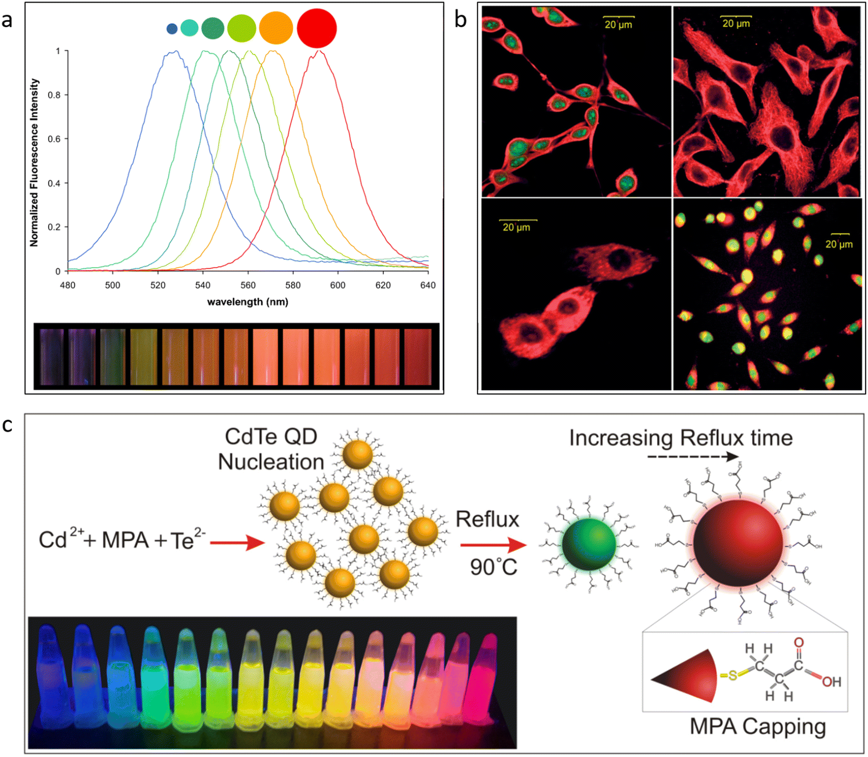 | ||
| Fig. 3 (a) Change in fluorescence with the change in the size of the CdSe quantum dots.92 Reproduced with permission from ref. 92. Copyright 2010. Wiley-VCH. (b) Duel-colored quantum dots for application in bioimaging.77 Reproduced with permission from ref. 77. Copyright 2007. Wiley-VCH. (c) Surface functionalization of CdTe quantum dots.83 Reproduced with permission from ref. 83. Copyright 2016. Elsevier Ltd. | ||
It is interesting how a toxic metal-based system has been so widely used in several sensing and bioimaging applications. There are some limitations in the use of cadmium-based quantum dots. The toxic effects of cadmium were previously studied. Here, we would refer to the cytotoxicity of the cadmium-based quantum dots. In 2009, King-Heiden et al. found that cytotoxicity of cadmium-based quantum dots can happen in two processes. Firstly, the degradation of the quantum dots ultimately led to the release of cadmium into the surroundings. Secondly, they can give rise to reactive oxygen species, which can have negative impacts on cell biochemistry.84 So, the question remains unanswered whether to use CdTe, CdSe like quantum dots or not. The toxicity caused by these types of quantum dots is solely dose-dependent, so at a minimal dose, they can still be used.85 Here, the toxicity study of cadmium-based quantum dots is studied only in a cell culture environment, and further research is needed to put forth a paradigm of toxic effects in large complex biosystems. Rather than finding the toxicity of the highly fluorescent cadmium-based quantum dots like CdTe and CdSe, one must look forward to the dosage dependence on the toxicity of these types of quantum dots. It is essential to put standardized data for the optimum dosage of these quantum dots, whether it is any biological or fluorescence application.85 Studies have found that large dose exposure to CdTe quantum dots can cause tissue damage to the male reproductive tissues of mice. But it was considered relatively safe at a very low dosage and did not damage the reproductory system in male mice.86 More similar studies are required in this field to understand the practicality of using cadmium quantum dots.
In the sensing as well as bioimaging applications, one better option is to avoid the controversies of the use of cadmium quantum dots and rather, more focus on the synthesis of non-toxic carbon-based quantum dots should be given. There are several instances where carbon-based quantum dots are more advantageous than cadmium quantum dots. Firstly, carbon quantum dots have no safety and environmental concerns like cadmium quantum dots.87 Carbon quantum dots offer better scalability, biocompatibility, and photostability.88 Under optimized conditions, carbon quantum dots can also offer a high quantum yield similar to that of cadmium quantum dots.30,89–91 From the application point of view, it totally depends on the mechanism of sensing. One could opt for non-toxic quantum dots, but when options are not available, one should go for cadmium quantum dots as they are very efficient when not taking into consideration the toxicity parameters.
When we think about the synthesis process through the hydrothermal pathway, is it really so simple to create CQDs from any natural precursors? The answer could be yes. Consider flowers as an example. Several publications have focused solely on the creation of CQDs from flowers.93–100 Flowers are constituted entirely of carbon; thus, it stands to reason that when they are subjected to hydrothermal treatment, a greater or lesser amount of carbon nanoparticles will arise. Fig. 4a–h shows that these natural precursor-generated CQDs have been used for the detection of metal ions and different organic compounds.94,96 But it must be obvious that these materials have never been marketed because of many factors, restricting their selectiveness towards various compounds. QDs made from reagent-grade materials offer higher selectivity when compared to the selectivity of these materials, and because of this, they have been used for ratiometric detection of various metal ions and other species. Fig. 4a–h represents quantum dots prepared from marigold,93 cherry blossom flowers,94 Gardenia,95 Sunflower,96 Rose,97 Forsythia,98 Carnation,99 and Chrysanthemum,100 respectively.
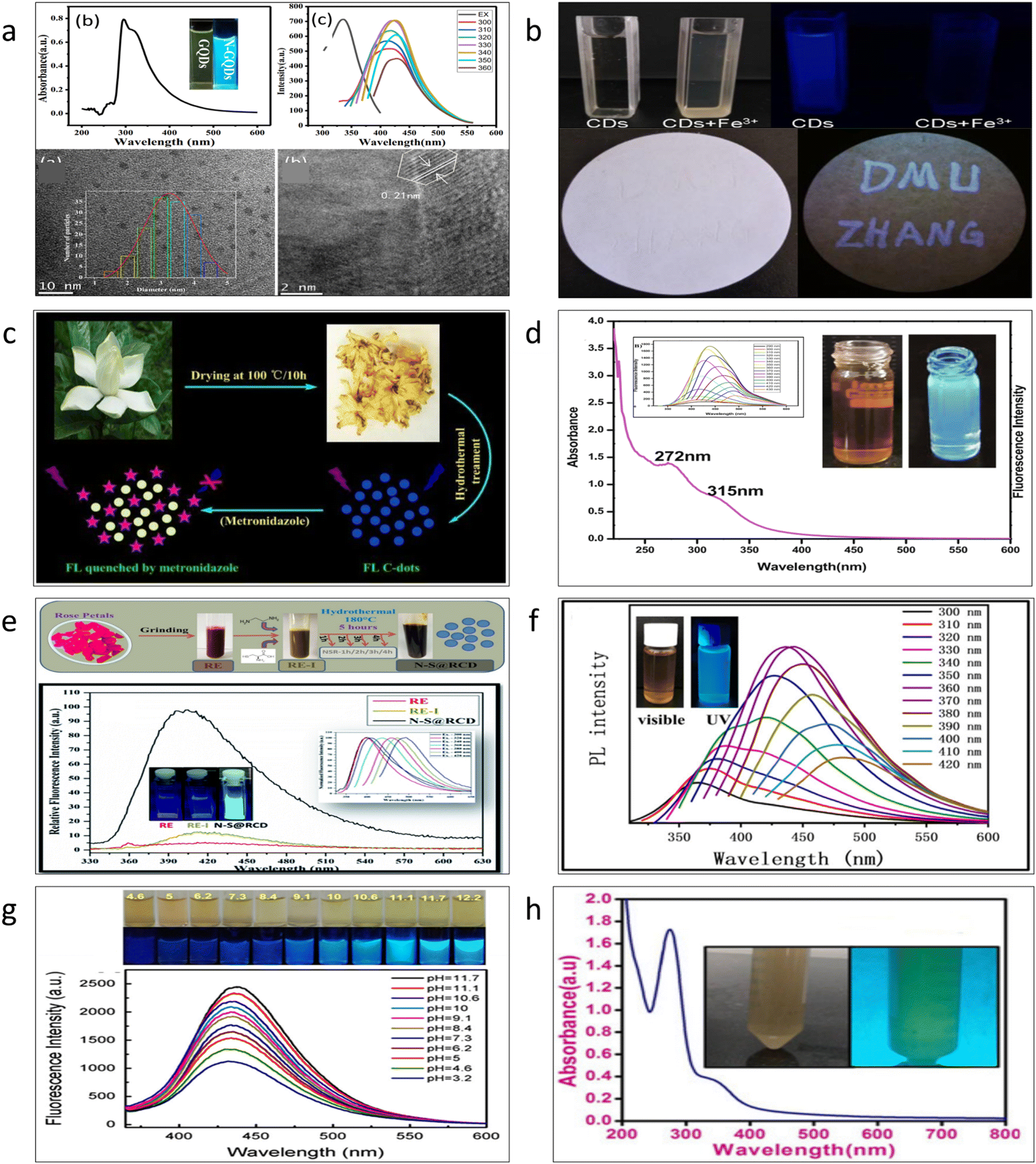 | ||
| Fig. 4 Preparation of different carbon quantum dots from natural precursors (a) Marigold93 adapted with permission from ref. 93 Copyright 2019. Elsevier Ltd. (b) Cherry blossom flowers94 Adapted with permission from ref. 94 Copyright 2019. Elsevier Ltd. (c) Gardenia95 (Open Access) (d) Sunflower96 Adapted with permission from ref. 96 Copyright 2021. Elsevier Ltd. (e) Rose97 adapted with permission from ref. 97. Copyright 2019. Royal Society of Chemistry. (f) Forsythia98 adapted with permission from ref. 98 Copyright 2021. Elsevier Ltd. (g) Carnation99 Adapted with permission from ref. 99 Copyright 2016. Elsevier Ltd. (h) Chrysanthemum100 adapted with permission from ref. 100 Copyright 2019. AIP Publisher. | ||
4. Trend of ratiometric mixing of quantum dots
The fabrication of complementary color-emitting sensor material utilizing quantum dots and other materials has been the subject of several studies. Heavy metals, metals, non-metals, organic chemicals, biomolecules, and explosives were all detected using these sensor probes.81,82,101,102 The usage of ratiometric sensor materials has led to current advances that have improved the capacity of the material for sensing. They have made it possible for distinct compounds to be detected by the naked eye using complimentary color fluorescence emission. One does not need an additional objective setup to measure the change in fluorescence emission spectra when using this ratiometric QD system. These materials have the potential to significantly reduce the price of conventional qualitative procedures used for the identification of a chemical in trace levels if they are commercialized. In comparison to QDs made from natural precursors (mainly carbon quantum dots), reagent-grade materials often produce better sensing outcomes. There may be many causes for this. The majority of ratiometric sensing CQDs have been made using reagent-grade components. To maximize detection capabilities, further functionalization has been done in various CQDs. Different chemical reagents can be used for functionalization. Most frequently, certain organic compounds are chosen for this function.4.1. Metals and heavy metals
The development of ratiometric sensor probes for the detection of metals and heavy metals is one of the most effective efforts in sensing using quantum dots. The environment has been severely harmed by the pollution caused due to the last century's rapid industrialization. Mercury,103 arsenic,104 chromium,105 and other metal ions are known to be harmful to human health and are needed to be detected at trace levels. Researchers are currently working nonstop to develop sensors that can find minute levels of these various metal pollutants in water supplies and other sources. For the detection of traces of metal ions in samples, several of them have shown to be particularly successful and efficient. The production of fluorescence sensor probes in a ratiometric mixture is one of the current research themes. Additionally, the utilization of such sensor probes can successfully identify this metal species. These projects aim to replace advanced equipment including inductively coupled plasma mass spectrometry (ICP-MS),106 atomic absorption spectrometry,107 and stripping voltammetry.108 Even though these devices produce data with a high degree of precision and accuracy, using them for analysis comes at a considerable cost and necessitates a highly qualified professional operator.Fig. 5 demonstrates the research on using quantum dots in a ratiometric mixture to detect metals. This applies to poisonous metals, including lead, arsenic, and mercury, metals like copper and iron that are not poisonous, as well as the detection of precious metals like silver. Many systems do not allow QDs to independently detect metals with very low LOD (limit of detection). To reduce the LOD in this situation, QDs have frequently been functionalized. Fig. 5a and e show the application of two alternative CQDs. One of them was blue emissive CQD, while the other was red emissive CQD. The blue CQD is seen to quench in both circumstances, whereas the red CQD's fluorescence is unaffected. The affinity of Hg2+ for the carboxylic and sulfhydryl groups on the surface of QDs may be the cause of the quenching process due to presence of Hg. According to Wang et al.,101 the carboxyl group on the surface of blue CQDs might chelate sites to Pb2+ in the case of lead. In order to quench fluorescence, it has been discovered that the formation of blue CQD/Pb2+ complexes raises the absorption peaks of the metals. To support the theoretical arguments, analysis was done on the UV-vis absorption spectra of Pb2+ and the excitation spectra of the blue CQDs in the system. It was discovered that Pb2+ absorbs the stimulating light because its absorption peak (328 nm) overlaps with the excitation spectrum of the blue CQDs (342 nm), which results in the fluorescence quenching of blue CQDs as a result of the inner filter effect (IFE). Iron was identified in Fig. 5b using QDs. This is an uncommon instance of ratiometric QD combinations. Here, a single CQD was employed by Deng et al.109 Rhodamine 6G moieties that were covalently linked made up the CQD surface. It has been explained that the FRET (Förster resonance energy transfer) between ring-opened Rhodamine 6G and CQDs drives the entire process of detecting Fe(III). Here, the Fe3+ initiates the FRET process by causing the spirolactam ring of Rhodamine 6G to change to its open-ring state, and the material exhibits excellent iron selectivity in both solution and solid states. Fig. 5c, d and f shows how to employ QDs to detect copper, silver, and arsenic, respectively. A red emissive CdTe QD and a second blue emissive CQD have both been employed in each instance. Although comparable QDs were employed in this research, the mechanisms by which the fluorescence was quenched in each case differed. By using MPA (mercaptopropionic acid), the CdTe QD for copper detection has been functionalized. According to the justification, the MPA-Cu2+ complex's high-affinity constant causes fluorescence quenching.78 DTT and GSH have been employed to functionalize the CdTe QDs for arsenic detection. Since it creates a strong sulfur-arsenic bond, the thiol component of these compounds is a well-known binder with arsenic.80 Mercaptosuccinic acid110 and L-cysteine111 were also employed for the detection of arsenic in the aqueous medium in other references. Here, two quantum dot systems were represented by the work. The cyan-colored fluorescence emission of m-phenylenediamine was used to create the carbon quantum dot. While as a precursor for red quantum dots, cadmium telluride, was utilized. The graph demonstrated that the functionalized quantum dot has a 5 ppb limit of detection for arsenic. The red quantum dots that are present in arsenic-containing environments get quenched as a result of the mixing of the two distinct quantum dots, but the emission intensity of the cyan carbon quantum dots does not change. Consequently, a broad color spectrum is created for arsenic detection. While the potential quenching mechanism for the detection of silver (Fig. 5d) might be caused by ion exchange between CdTe QDs and Ag(I).79 TEM was used to corroborate this idea. The lattice of red CdTe QDs changes from 0.27 nm to 0.21 nm when Ag(I) is added. The modification demonstrates that the creation of the weakly photoactive Ag2Te layer on the surface of CdTe is the consequence of the ion exchange process between the CdTe QDs and Ag(I). This occurs as the binding ability of Ag–Te is greater than Cd–Te.
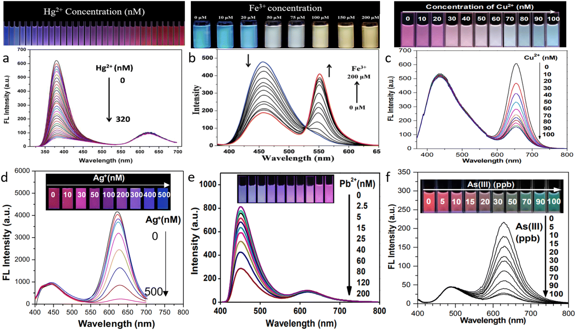 | ||
| Fig. 5 Ratiometric detection of different metals by quantum dots and other fluorescent materials (a) mercury101 (b) iron109 (c) copper78 (d) silver79 (e) lead112 (f) arsenic.80 Reproduced with permission from ref. 101, 109, 78, 79, 112 and 80. Copyright 2018, 2016, 2016, 2020, 2019, 2016. Royal Society of Chemistry, Royal Society of Chemistry, Royal Society of Chemistry, Springer Nature, American Chemical Society, American Chemical Society. | ||
When working on ratiometric sensing utilizing QDs, most of the time, the effort has been given to creating a paper-based test kit as an inexpensive visual test kit. The cost of detecting these metals, which calls for expensive specialized gear, would be reduced if these test kits were successfully marketed. Additionally, they could be easily accessible as a field test kit. Due to the simplicity of the operating mechanism, even those without a background in science may utilize them. A paper-based sensor that can more swiftly, effectively, and economically detect metal ions visually may be created using a ratiometric fluorescent probe printed on ordinary paper or a microporous membrane. Fig. 6 shows some of the paper-based fluorescent probes for the detection of various metal ions. The color contrast shown by these works could easily be distinguished by the naked eye. Fig. 6a–f represents paper-based sensors developed using a ratiometric combination of fluorescent materials for testing mercury, arsenic, iron, silver, copper, lead, and copper, respectively.
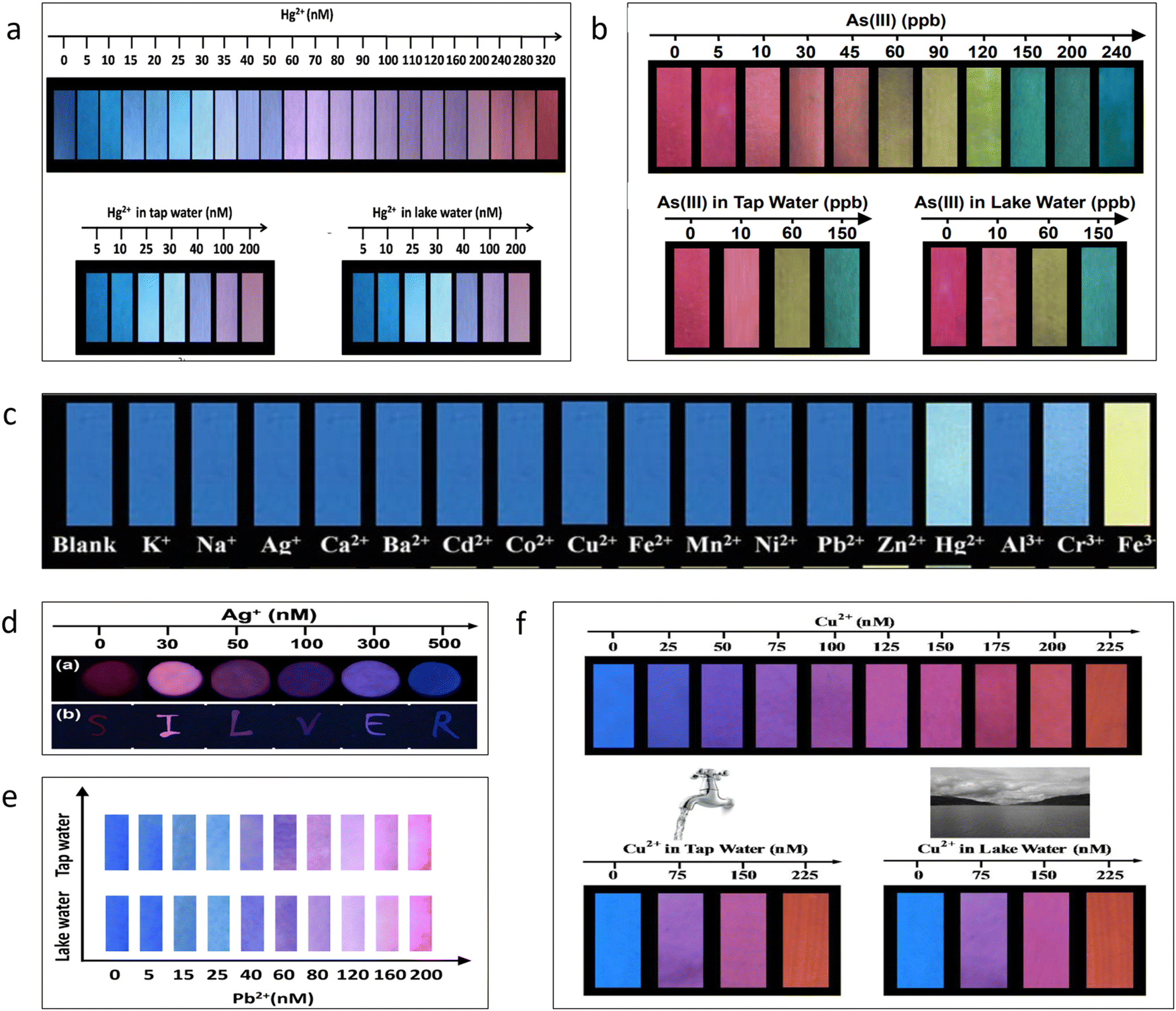 | ||
| Fig. 6 (a) Detection of mercury by fluorescent test paper.101 (b) Detection of arsenic by fluorescent test paper.80 (c) Detection of iron by fluorescent test paper.109 (d) Detection of silver by fluorescent test paper.79 (e) Detection of lead by fluorescent test paper.112 (f) Detection of copper by fluorescent test paper.113 Reproduced with permission from ref. 101, 80, 109, 79, 112, and 113. Copyright 2018, 2016, 2016, 2020, 2019, 2016. Royal Society of Chemistry, American Chemical Society, Royal Society of Chemistry, Springer Nature, and American Chemical Society, and Royal Society of Chemistry. | ||
4.2. Non-metals
Cyanide is acknowledged as a chemical species that is particularly harmful to human health. The World Health Organization (WHO)114 states that the maximum allowable quantity of cyanide in drinking water is 1.9 μM. Cyanide's severe toxicity is brought on by its binding to iron in cytochrome c oxidase, which can induce hypoxia.115 Fluorine, as opposed to cyanide, is a necessary element that strengthens bones and teeth to ward against osteofluorosis and dental caries. They are used to treat problems of the bones and are frequently present in toothpaste for this reason. Fluorine is beneficial yet extremely dangerous when present in excess since it can lead to a number of health issues. As a result, sensor equipment must be ready for the identification of this species in aquatic bodies. The procedure for detecting these ions using QDs is depicted in the accompanying Fig. 7a; similar to the metal sensors, a paper-based fluoride sensor probe has also been created. The test kit is prepared using the same technique as the aforementioned sensors. Using a standard jet printer, the created QD ink is imprinted on the surface of the paper. The procedure is done a few times to improve the paper coating and fluorescence intensity. The test paper is then checked under a UV lamp source to get the fluorescence output.116 In another work by Devi et al., graphitic carbon nitride and graphene quantum dots were used for the detection of fluoride ions in water. The result obtained a detection limit of 4.06 μM.117 Similarly, in the case of cyanide shown in Fig. 7b, a blue CQD was used to prepare a ratiometric sensor probe along with a red-emitting gold nanocluster. This sensor is capable of detecting trace amounts of cyanide in various vegetables and water sources.102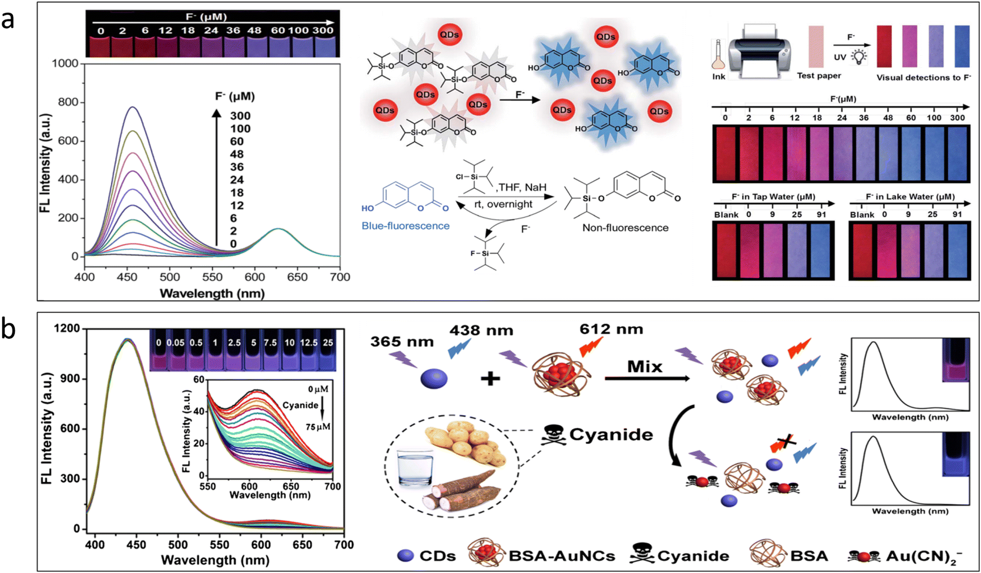 | ||
| Fig. 7 (a) Detection of fluoride by the use of ratiometric sensing.116 Adapted with permission from ref. 116. Copyright 2017. Royal Society of Chemistry. (b) Detection of cyanide by the use of ratiometric sensing.102 Adapted with permission from ref. 102. Copyright 2019. Springer Nature. | ||
4.3. Other biomolecules
QDs have been applied in the detection of a number of different other chemical substances, such as explosives, biomolecules, tetracycline, and other organic moieties, in addition to detecting metals and non-metals.81,82,118 Different ratiometric probes are shown in Fig. 8. There are several impacts of TNT not only on the environment but also on health and security concerns. In Fig. 8a, CdTe QDs were used throughout the whole TNT detection procedure. By encasing the red-emitting QDs as the core and the green-emitting QDs as the shell in silica nanoparticles, the two distinct QDs have been recreated. Another method for lowering the detection limit was also disclosed; in this case, printing matrices were substituted with mesoporous silica particles. In the second step, it was discovered that additional recognition sites were only present on the silica shell's surface.81 It was found that the TNT interacts with molecular detecting sites to limit the emission of green QDs. For both the detection of glucose and ascorbic acid completely, similar testing patterns were performed, as shown in Fig. 8b–c. The enzyme glucose oxidase may catalyze the oxidation of glucose to produce H2O2, which transforms Fe2+ ions into Fe3+ ions. In order to identify Fe3+ ions, which in turn would aid in the detection of glucose, this chemical feature of glucose has been employed. Here, two unique QDs have been employed. The red emission was produced using a CdTe QD, while the blue emission was made using a CQD. It was explained that the excited electron in the CQDs is transported to the half-filled 3d orbitals of Fe3+ present.56 As a result of this, the emission efficiency of the CQDs gets quenched. According to the article, this method may enable the development of paper-based test kits that might aid in the detection of blood glucose levels and potentially provide findings for abnormal blood glucose levels.119 The procedure for detecting ascorbic acid was quite similar to that used to find Fe3+ in the instance of glucose. The CQDs employed here between the two QDs first get quenched in the presence of Fe3+. It has been discovered that the fluorescence of the blue CQD is recovered in the presence of the solution medium. This results from the decrease of Fe3+ to Fe2+, which has no impact on the quenching of fluorescence.120 For the detection of dopamine, CdTe QDs used have been functionalized by the use of thioglycolic acid. As a result, the emission of the CdTe QDs got quenched in the presence of dopamine, Fig. 8d. The explanation for this quenching mechanism is due to an electron reaction.118 In another work, boric acid-functionalized tungsten disulfide QDs were used for the detection of dopamine. The result obtained showed aggregation of fluorescent probes and inner filter effect in contact with dopamine.121 Tetracycline (TC) is a type of broad-spectrum antibiotic.15 But they have been found to cause drug residues in animals. If this residue is left unchecked in the food chain, it can give rise to antibiotic-resistant bacteria or other toxicity effects.122 Here, Fig. 8e shows green emissive CdTe QDs used to build a ratiometric probe for the detection of tetracycline and red emissive Eu3+ was chelated on the surface of the QDs. A hybrid nanosensor was made by chelating with the aid of 3-mercaptopropionic acid. It was shown that the electron transfer pathway from CdTe QDs to Eu3+ causes the emission of CdTe QDs without tetracycline to be somewhat diminished when combined. Additionally, the quenching action of coordinated water molecules causes the emission of CdTe QD to progressively decrease. As a result, the sensor displays green fluorescence in the absence of tetracycline. Han et al.82 suggested that due to the increased coordination strength of Eu3+, tetracycline might substitute water molecules to coordinate with Eu3+ and transfer the absorbed energy to Eu3+. This would cause the red fluorescence of the Eu3+ to emerge via the antenna effect. Here, it was observed that two emissions continue to alter as TC increases. Electron teleportation from CdTe QD surface traps to the europium–tetracycline (Eu-tetracycline complex) promotes non-radiative electron–hole (e−/h+) recombination annihilation on the surface of CdTe QDs, resulting in continual quenching of CdTe QDs. In this work, a sensor that can identify acetaminophen and arginine simultaneously has been suggested. An on–off–on sensor was the foundation of the sensing pattern. Specifically, a green emissive fluorescent dye (calcein) and a blue emissive N-CQD were combined to design this sensor Fig. 8f. It was discovered that taking arginine together with N-CQDs quenches the blue emission. This is because arginine is an amino acid with a positive charge, and N-CQDs have a lot of hydroxyl and carboxyl groups on their surface. The quenching of the N-CQDs' fluorescence was shown to be mostly caused by an interaction between the carboxyl and guanidine groups. However, the sensor and arginine complex system's blue fluorescence was restored when acetaminophen was introduced. The main cause of this is the stronger interaction between acetaminophen and arginine than the arginine/N-CQD combination.123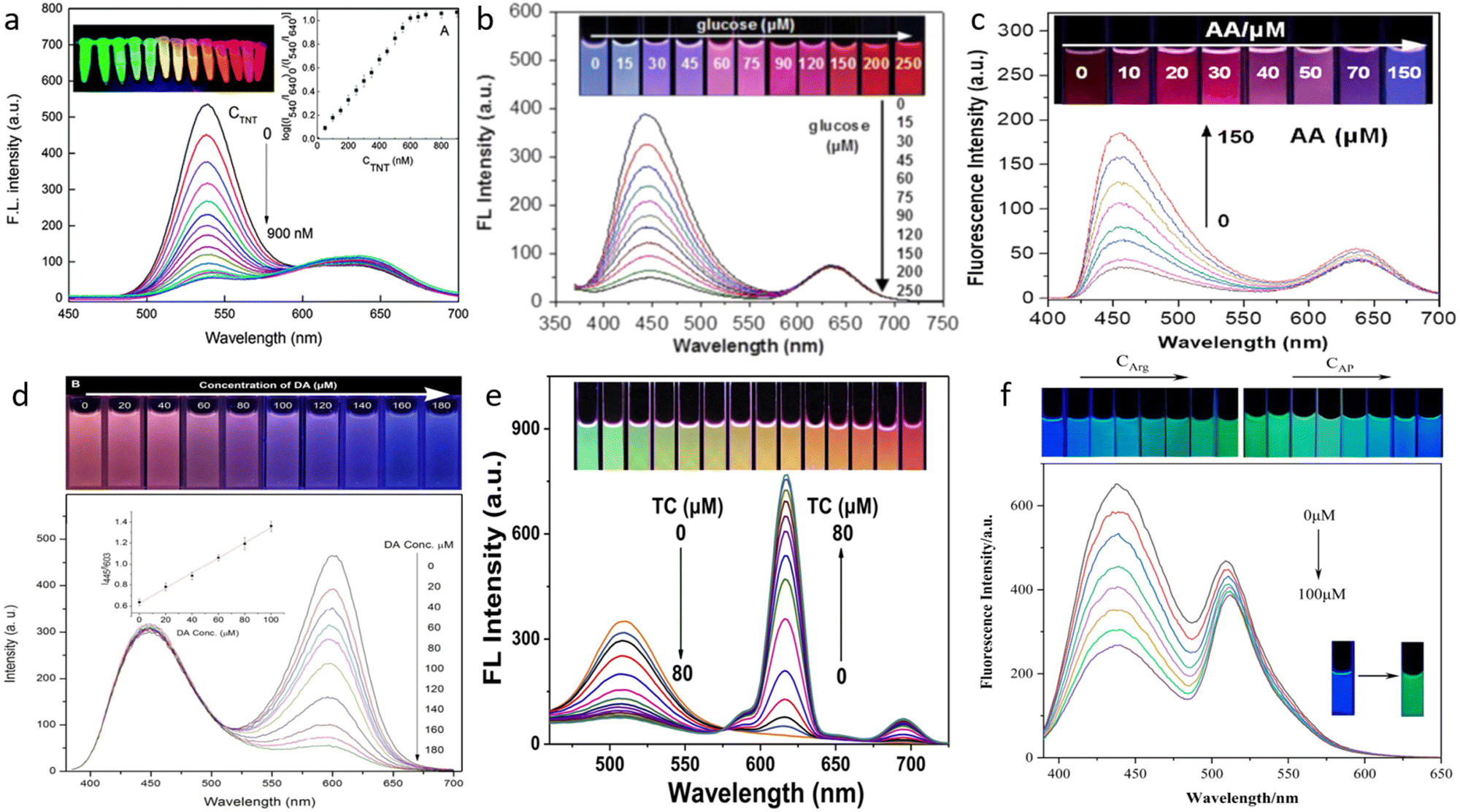 | ||
| Fig. 8 Detection of different varieties of organic compounds using quantum dots. (a) Trinitrotoluene81 (b) Glucose119 (c) Ascorbic acid120 (d) Dopamine118 (e) Tetracycline82 (f) Acetaminophen and arginine.123 Reproduced with permission from ref. 81, 119, 120, 118, 82 and 123. Copyright 2014, 2016, 2021, 2017, 2020, (Open access MDPI, 2022). Royal Society of Chemistry, Elsevier Ltd, Elsevier Ltd, Royal Society of Chemistry, Elsevier Ltd, MDPI. | ||
5. Sensing mechanism of the quantum dots
Quantum dots are categorized for use in sensing based on their ability to reduce fluorescence emission in the presence of a certain analyte. Seeing how the QD reacts to various substances, both with and without an analyte present, is also very important. The identification and optimization of the quantum dots' potential sensing mechanism are necessary for large-scale synthesis for mass production. If these factors could be adjusted, then better LOD would surely follow. Quantum dot fluorescence is influenced by a number of variables, including static quenching, dynamic quenching, FRET, PET, and others. The various quenching mechanisms are demonstrated in Fig. 9. Fluorescence is influenced by self-quenching, pH effects, and other factors, which can have an impact on how an analyte is detected.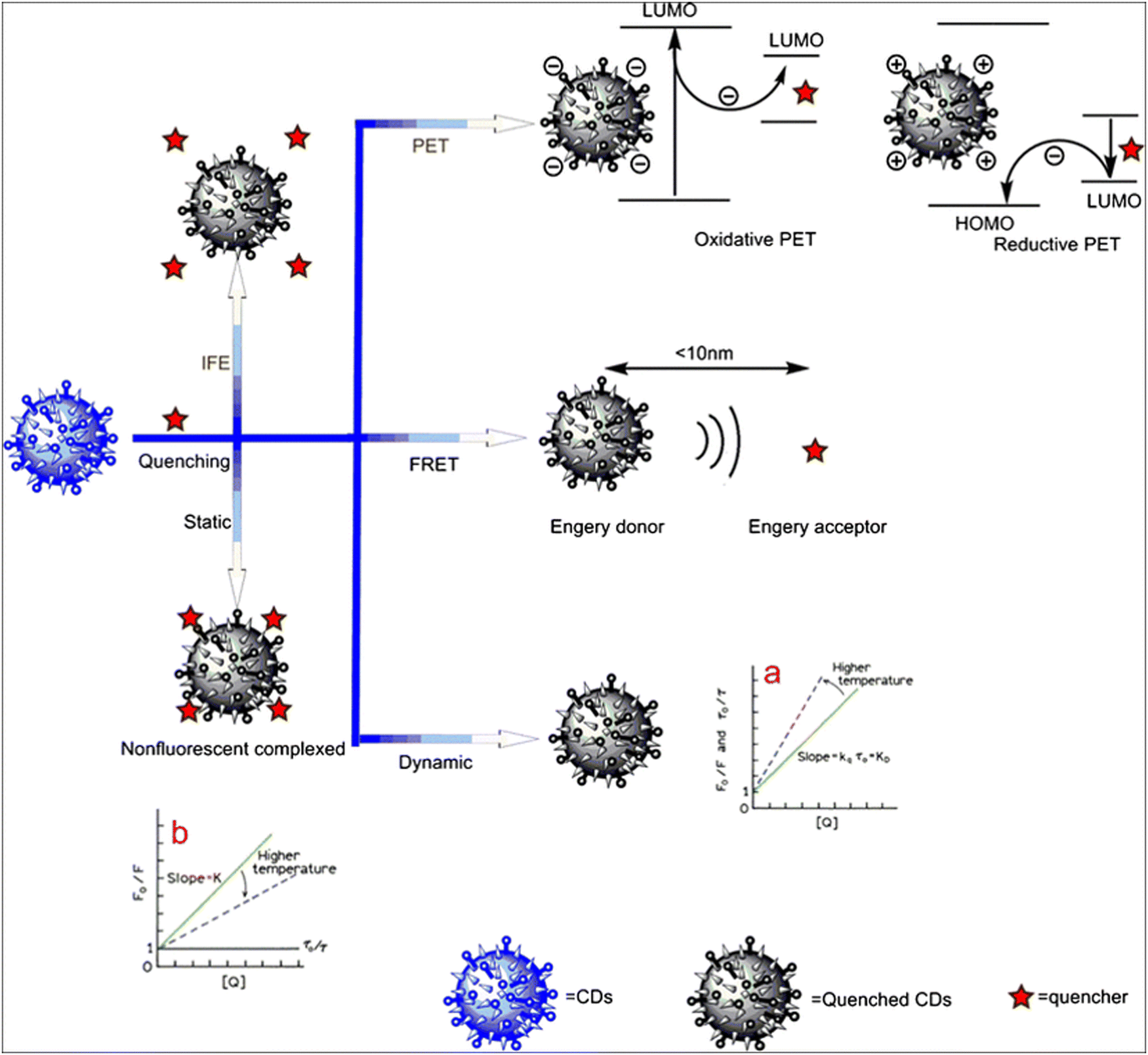 | ||
| Fig. 9 Different quenching mechanisms used for the detection of various analytes.124 Reproduced with permission from ref. 124. Copyright 2017. Springer Nature. | ||
5.1. Static quenching
The formation of a non-fluorescent compound between the fluorescent molecule and the quencher molecule results in static quenching. A complex is first formed between the quencher molecule and the fluorophore. When exposed to radiation after the complex molecule has formed, the excited complex goes to an excited state. When these excited molecules release their energy, it does so non-radiatively. The molecule is considered to be statically quenched when the complex's ground state is non-fluorescent. Hong Wu et al.125 found that the emission intensity of sulfonic-GQDs was quenched with the addition of Fe3+ ions. The explanation for this is said to be due to the static quenching mechanism. There were two factors that led to this conclusion. Firstly new FTIR peak was confirmed after the introduction of Fe3+, indicating the formation of a chemical bond. Secondly, TEM images found that the introduction of Fe3+ led to the agglomeration of GQDs and Fe3+. Static quenching is mainly observed in the ground state. Therefore, the absorption spectrum changes due to these types of quenching.5.2. Dynamic quenching
Collisional quenching is another name for dynamic quenching. Another way it can happen is when a quencher molecule interacts with a fluorescing material, transferring non-radiative energy from the fluorescing substance to the quencher with no or decreased fluorescence. The collision between both the fluorophore and the quencher molecule is the primary driver of this energy transfer mechanism. The average lifespan of the fluorescent molecule diminishes as the quencher molecule's concentration rises. A work by Chatterjee et al.23 found that boron and sulfur co-doped GQDs were able to selectively detect dopamine. They discovered that the average lifespan of the fluorophore decreased as dopamine levels increased. According to the linear Stern–Volmer trend, the dynamic quenching process may be the cause of the potential quenching mechanism. How to recognize this class of quenching mechanism becomes a key consideration. It has been claimed that the distinction between static and dynamic quenching processes may be made by contrasting the fluorophore's absorption spectra before and after quenching. The fluorophore's absorption spectra reportedly change during the course of the static quenching procedure but remain unchanged during the dynamic quenching phase.91 To prove the occurrence of dynamic quenching, one must test the lifetime of the fluorescence. In the case of dynamic quenching, there is a decrease in the slope of the photon counts measured in lifetime measurement. Dynamic quenching is mainly observed in the excited state. Therefore, the lifetime of the fluorophore changes due to this type of quenching. A schematic diagram demonstrating the combined mechanism of the static and dynamic quenching process is demonstrated in Fig. 10. A represents the fluorescent probe, and Q is the quencher.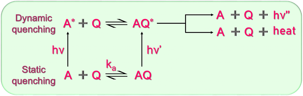 | ||
| Fig. 10 Schematic diagram showing the combined mechanism of static and dynamic quenching. | ||
5.3. FRET (fluorescence resonance energy transfer)
Fluorescence resonance energy transfer is one of the unique examples of fluorescence quenching. Two distinct kinds of fluorescent molecules are present in this method of energy transfer, and they are located fewer than 10 nm apart from one another. Thus, the acceptor molecule absorbs the donor's fluorescence energy, which causes the acceptor molecule to emit fluorescence. This phenomenon of resonance energy transfer can be subdivided into three categories, BRET (bioluminescence resonance energy transfer),126 CRET (Chemiluminescence resonance energy transfer),127 and FRET (Förster or fluorescence resonance energy transfer).128 As the name suggests, in BRET, the energy-donating substance is a bioluminescent molecule; for CRET, it is a chemiluminescent molecule. For FRET, it is a fluorescent molecule, but in all cases, the acceptor molecule is a fluorophore. In the above-mentioned ratiometric sensor probe by Deng et al.,109 carbon quantum dots are covalently coupled with Rhodamine 6G. It was found that Rhodamine 6G moiety changes to an energy acceptor in the presence of Fe3+. FRET system works in an operating distance ranging from R0 ± 50% R0 between dipole–dipole. Here, R0 is known as the Förster critical distance.129 In a study by Wang et al.,130 gold nanoparticles were combined with CQDs as a ratiometric FRET-based probe for the detection of both lead and copper. The binding of the gold nanoparticle with the CQDs was only based on an electrostatic interaction in the aqueous phase. Here, the CQDs acted as a donor molecule and the gold nanoparticles acted as an acceptor molecule. Comparing static quenching and FRET, strong coupling takes place in static quenching between the quencher and fluorophore, whereas there is a weak coupling between the donor and acceptor molecule in FRET. The mechanism of FRET is demonstrated in Fig. 11. The spectral overlap shows the emission wavelength, which helps in the excitation of the acceptor molecule.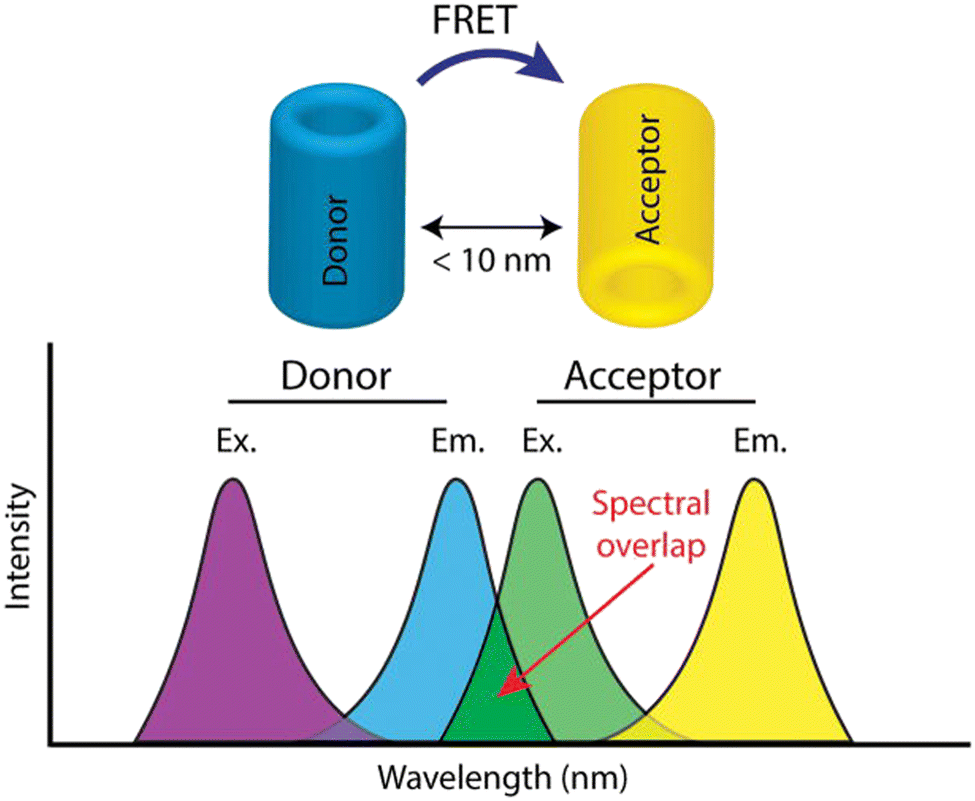 | ||
| Fig. 11 Schematic diagram showing the combined mechanism of Förster resonance energy transfer (FRET).131 Reproduced with permission from ref. 131. Copyright 2017. Elsevier Ltd. | ||
5.4. PET (photoinduced electron transfer)
As the name suggests, this is a process of transfer of electrons from the electronically excited state of the donor molecule to the acceptor molecule. A redox reaction frequently occurs when electrons are transferred from one molecule to another.132 When an excited fluorophore molecule contributes an electron to a quencher molecule, the latter is reduced, and the former is oxidized in the process. In this instance of PET, the fluorophore may function both as a potent reducing and oxidizing agent. Thus, in this case, the singly occupied molecular orbital electrons can serve as both oxidizing and reducing agents following excitation. The single electron in the excited state can function as a reducer, whereas the hole formed in the lower excited state can function as an electron acceptor. Besides its use as a fluorescent sensor, the PET technique is also used in photovoltaic cells, and photocatalysis. A work by Callan et al. in 2008 showed that when CdSe–ZnS quantum dot is functionalized with 1-(2-mercapto-ethyl)-3-phenyl-thiourea in the fluorophore–spacer–receptor format, it works as a receptor for the detection of different anions by PET mechanism.132 Similarly, another work where CdTe and ZnS core QD was used for the detection of Hg in an aqueous medium was also by the same PET mechanism.1335.5. IFE (inner filter effect)
The inner filter effect is caused when the absorbance spectra of the quencher molecule or atom coincide with the emission spectra of the fluorophore molecule, as a result of which the emitted energy is taken up by the quencher molecule. In comparison to alternative fluorescence quenching mechanisms (e.g., photoinduced electron transfer (PET) and fluorescence resonance energy transfer (FRET)),134 IFE has been demonstrated to be a very effective and efficient strategy tool for turning analytical absorption signals into fluorescence signals.6. Sensing parameters and upscaling
Four essential parameters for a successful QD sensor are demonstrated in Fig. 12. The optimization of the sensing parameters depends mainly on the effective functionalization and maximum change in fluorescence intensity of the quantum dots. Effective functionalization determines how efficiently the analyte is sensed by the functionalized molecule. The most important factor that provides visual change is the change in the fluorescence intensity pattern. An electrochemical sensor like that of the dropping mercury electrode, which is extremely effective, this present-day paper-based sensor is still underdeveloped. For commercial upscaling, better contrast needs to be achieved for highly precise data. Efforts are needed for the sustainable development of the pilot scaling strategy. From an industrial point of view, batch reactors and continuous reactors are needed to be developed for the gram-scale synthesis of the sensor material. In the case of industrial production, continuous reactors would always be preferred over batch reactors. But here, the objective of preparation should be quality over quantity of the quantum dots. If the case scenario is that due to mass production, the effective functionalization and other parameters on which the LOD depends get compromised, it would not be of much utility then. Another parameter of high quantum yield adds up when speaking of a paper-based portable sensor, which is the quantum yield. For the preparation of a portable device for multi-ion detection, as shown in Fig. 1, it is extremely necessary to have a higher quantum yield for better visual qualitative and quantitative detection.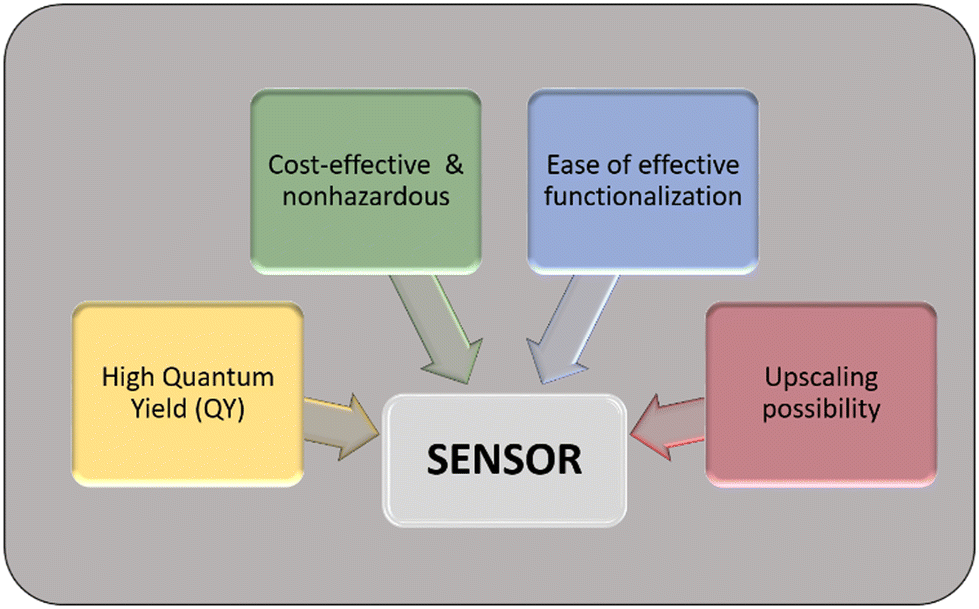 | ||
| Fig. 12 Essential parameters for the development of a QD-based fluorescent sensor. | ||
Considering the upscaling possibilities, it must be pointed out that it is important to look forward to the CQDs and GQDs research. The reason for this biased statement is due to the toxic and harmful effects of inorganic QDs like CdTe QDs. Moreover, it is also important to point out that inorganic QDs have complex synthesis procedures compared to carbon-based QDs. Taking in consideration both the factor of toxicity and production cost, it would be better to avoid inorganic QDs until and unless the results from it provide exceptionally high LOD and low environmental hazards. An important aspect is to give more priority to the CQDs, as in several studies, it has been found that they can give rise to high quantum yield (above 70%).30,90,91,135 High quantum yield is an essential parameter for the upscale production of a naked-eye fluorometric field test kit. It is evident that the fabrication of quantum dots is an extremely cost-effective sensor compared to other fluorescent materials. Very low cost commonly found precursors, for example, citric acid, can give rise to highly fluorescent quantum dots. The objective should be to decrease the LOD observable to the naked eye, keeping in consideration the low cost and low toxicity of the nanomaterials used. Of the various combinations for a possible ratiometric sensor, the best-case possibility would be to have highly fluorescent carbon quantum dots along with another complementary colored carbon quantum dot or any other categories of quantum dots or any other low-cost fluorescent chemicals like RhB.136 Another approach by which LOD can be lowered is by increasing the adsorption capacity of the sensor for that particular analyte. In a study by Lin et al., CQDs were encapsulated inside ZIF-8 MOF. As a result of this modification, the adsorption capacity for the analyte (Cu2+) was increased by the MOF and thus enabling better detection of the analyte.137 Very recently, another work by Chai et al. also demonstrated how CQDs could be used with MOFs for the detection of sulphide ions. In this work, two-dimensional copper-based zinc porphyrin MOF nanosheets (2D Cu–TCPP(Zn)) were mixed with blue fluorescent CQDs. In the absence of the sulphide ions, the CQDs/(2D Cu–TCPP(Zn)) emitted blue fluorescence. (2D Cu–TCPP(Zn)) has no fluorescence due to the LMCT effect. But in the presence of sulfide ions, they bind to the Cu node resulting in the disintegration of (2D Cu–TCPP(Zn)). The TCPP(Zn) molecules display red fluorescence and thus act as a ratiometric sensor.138
7. Recent works on carbon quantum dots as a sensor material
In context to the upscaling perspectives, the most favorable systems for use in the ratiometric sensor devices could be CQDs. The scope of ratiometric sensors is not only limited to only detection of analytes in water rather could be implemented in nanotechnology, for example, in optoelectronic and nano-electronic devices. In recent work, Han et al. prepared ratiometric colloidal quantum dots for measuring intracellular temperature. This shows that they could be easily implemented for the preparation of thermal sensors in nanoscale.139 New approaches are constantly being introduced for the detection of other emerging pollutants, such as pesticides.140,141 It is also reported that CQDs could be used as a fluorescent probe for the detection of hormones like progesterone. In a recent work by Cui et al., CQDs were used with graphene oxide (GO) as a FRET-based sensor for the detection of progesterone.142 Moreover, research is being conducted to bring forth new methodologies for detection systems, such as the use of a Scanning Kelvin Probe microscope (SKP) for the detection of volatile organic compounds (VOC). In the work by Selvaraju et al.,143 the work function and interactions of ethanol gas with the carbon quantum dots were investigated using SKP. This opens newer possibilities for characterization and sensing procedures in the market of sensors. A ratiometric fluorescent sensor is itself a very efficient sensor for naked-eye detection of the analytes. This ability could be further enhanced by the use of electronic monitoring devices like smartphone-based applications. Machine learning was used in recent works for generating algorithms for processing highly precise and accurate data for the detection of analytes. In a very recent work by Lu et al.,144 a polychromatic fluorescent-colorimetric paper sensor was designed. The uniqueness of the work is that it is assisted by a smartphone-based sensor, with simultaneous detection of Hg2+ and sulphide ions. Other than fluorometric sensors, carbon quantum dots are also gaining popularity in the application as electrochemical sensors by acting as an electrode material.145 The electrochemical performance of CQDs can be improved by designing composites with other materials.146 In recent work, Wei et al.147 prepared a sweat sensor based on the electrochemical performance of CQDs. The device was used for the electrochemical detection of cardiovascular biomarkers.8. Advantages of quantum dots over other fluorescent materials
The criteria of being advantageous and disadvantageous are totally parametric in nature. The deciding factor depends on multiple conditions. The conditions that might make quantum dots advantageous over metal–organic frameworks (MOFs) might be disadvantageous over molecular fluorescent emitters. The most obvious parameter in the upscaling process is the cost, which must be reduced as low as possible without hampering the output. The above example shows that quantum dots can be easily prepared with low-cost precursors using techniques such as microwave irradiation,148 solvothermal,149 and hydrothermal techniques.150 The work by Nammahachak et al. showed that size tunability could also be achieved in the hydrothermal synthesis pathway.150 It is well known that the size of nanoparticles affects their fluorescence properties. So the hydrothermal pathway could be a breakthrough by providing a simultaneous low-cost synthesis pathway for QDs and aiding in the size tunability. The preparation of MOFs is more complicated compared to quantum dots due to its complex purification process. Also, a high quantity of solvent is required to purify the MOFs in the rotary evaporator, which is both time-consuming and expensive. So, it is clear that in general quantum dots could be fabricated in low-cost methods but MOFs require more sophisticated reaction pathways. When talking of the yield, it is very easy to obtain a high quantity of molecular fluorescence emitters such as fluorescein dye. Fluorescein dye can be easily synthesized on a large scale by performing a common organic reaction, where phthalic anhydride reacts with resorcinol in the presence of ZnCl2. This reaction helps in the production of lab-scale fluorescein.151 In comparison, the synthesis of kilogram scale quantum dots is still in R&D and requires further studies.59 It might look advantageous that molecular fluorescent emitters could be synthesized on a large scale at a low cost compared to quantum dots and MOFs, but while pushing the parameter of yield, we are staying away from the selectivity and sensing parameters. Molecular fluorescent emitters might be easy to synthesize at a low cost and maintain a high quantum yield, but they have shown a low possibility for use as a sensor material.Here, we are focused on the preparation of a ratiometric sensor, so we need at least one material to have a fluorescence tunable property. In this parameter, quantum dots are highly advantageous over both MOFs and molecular fluorescence emitters. Quantum dots are renowned for their size-tunable nature.150 Since due to the size-dependent emission property, it is possible for the quantum dots to emit at a specific region of the electromagnetic spectrum. This property is generally observed in cadmium-based quantum dots152 and in carbon-based quantum dots150 and is generally absent in MOFs and fluorescent molecules like fluorescein, rhodamine B, and quinine sulfate. Besides having size-tunable fluorescent properties, quantum dots also possess narrow emission spectra, which is a strikingly good feature when compared to MOFs.153 Narrow emission peaks help in preventing spectral overlap or spectral bleed when combined with a complementary colored fluorescent material. This is one of the unique properties that place quantum dots above MOFs and fluorescent molecules while designing a ratiometric probe.
Based on all the above criteria, it could be predicted that quantum dots could be manufactured at an industrial scale in the future and may give rise to efficient fluorescent sensors. The present research in carbon quantum dots has already carved the road toward low toxicity compared to other metal-based quantum dots. If the cost of production is lowered compared to molecular fluorescent emitters without affecting the LOD, then surely quantum dots could serve as better fluorescent sensor materials.
9. Conclusions
The research on quantum dots is still far from comprehensive. These materials can be used in many different sectors. The creation of QLED displays using the spectacular fluorescence features of these semiconducting materials is one of the advanced research topics. More work must be performed into pilot-running these materials for utility in field test kits and counterfeiting applications if the scopes of these materials are to be expanded in future sensing devices. In this area of study, there are thousands of patents. According to reports, many QDs have the potential to be used in digital sensors on smartphones or paper-based next-generation sensing devices. For a better understanding of the product, some basic research is still needed for the usage of QDs on the pilot scale. Additional advances in this field of study could come from research that offer a better understanding of the well-defined and atom-specific structures, relationships between structure and properties, precise control of its fluorescence property depending on its fluorophore content, and controlled surface functionalization by different ligands for ppb level sensing by the naked eye. There is a continual need to monitor them due to the development of pollution in different industries. Products like ratiometric probes, which offer extremely affordable wide sensing scopes, naked-eye detection, and mass manufacture, might be the best option. Using smartphone-based applications may improve sensing even more. If improved, the smartphone-based program could not only be able to identify a specific drug but also define its quantitative components. For the betterment of the non-toxic and biocompatible sensors, more focus must be given to carbon-based nanomaterials (CQDs and GQDs). This would completely remove the toxic and harmful pollution-contributing effects of other metal-based semiconductor QDs. Moreover, these carbon-based compounds also provide a comparable quantum yield to that of metal-based QDs. So, it could be concluded that these nonmaterial could serve in the development of advanced, low-cost sensors. We have thoroughly explained some commonly used quantum dots in sensing applications and how they achieve a high limit of detection (LOD) in ratiometric combinations, some basic sensing processes, and how quantum dots can be industrially developed and combined to achieve future possibilities and usage to manufacture sensor devices as field test kits.Short terms
| QDs | Quantum dots |
| LOD | Limit of detection |
| nm | Nanometers |
| TMD | Transition metal dichalcogenide |
| CQDs | Carbon quantum dots |
| GQDs | Graphene quantum dots |
| TEM | Transmission electron microscope |
| QY | Quantum yield |
| XRD | X-ray diffraction |
| UV | Ultraviolet |
| CdTe | Cadmium telluride |
| HR-TEM | High-resolution transmission electron microscope |
| R-CQDs | Red carbon quantum dots |
| MPA | Mercaptopropionic acid |
| CdSe | Cadmium selenide |
| ICP-MS | Inductively coupled plasma mass spectrometry |
| IFE | Inner filter effect |
| FRET | Förster resonance energy transfer |
| WHO | World health organization |
| μM | Micromolar |
| TNT | Trinitrotoluene |
| TC | Tetracycline |
| N-CQDs | Nitrogen-doped carbon quantum dots |
| FTIR | Fourier transform infrared spectroscopy |
| BRET | Bioluminescence resonance energy transfer |
| CRET | Chemiluminescence resonance energy transfer |
| PET | Photoinduced electron transfer |
| ZnS | Zinc sulphide |
| R&D | Research and development |
| ZIF | Zeolitic imidazolate frameworks |
| MOF | Metal–organic framework |
| RhB | Rhodamine B |
| LMCT | Ligand to metal charge transfer |
| GO | Graphene oxide |
| VOC | Volatile organic compound |
| SKP | Scanning kelvin probe microscope |
| QLED | Quantum-dot light emitting diode |
Conflicts of interest
There are no conflicts to declare.Acknowledgements
We acknowledge Dr Uttam Kumar Ghorai and Ramakrishna Mission Vidyamandira for their thorough support for all kinds of assistance.References
- N. Baig, I. Kammakakam, W. Falath and I. Kammakakam, Mater. Adv., 2021, 2, 1821–1871 RSC.
- Q. Liu, J. Sun, K. Gao, N. Chen, X. Sun, D. Ti, C. Bai, R. Cui and L. Qu, Mater. Chem. Front., 2020, 4, 421–436 RSC.
- W. M. Yang, F. Liu, Y. T. Jin, Z. M. Dong and G. C. Zhao, ACS Omega, 2022, 7, 23555–23565 CrossRef CAS PubMed.
- A. M. Wagner, J. M. Knipe, G. Orive and N. A. Peppas, Acta Biomater., 2019, 94, 44–63 CrossRef CAS PubMed.
- A. Trinchi, T. H. Muster, S. Hardin, D. Gomez, I. Cole, P. Corrigan, A. Bradbury, T. L. Nguyen, M. Safai, G. Georgeson and D. Followell, IEEE Aerosp. Conf. Proc., Big Sky, MT, USA, 2012, pp. 1–9 DOI:10.1109/AERO.2012.6187252.
- M. A. Cotta, ACS Appl. Nano Mater., 2020, 3, 4920–4924 CrossRef CAS.
- S. Zhu, Y. Song, X. Zhao, J. Shao, J. Zhang and B. Yang, Nano Res., 2015, 8, 355–381 CrossRef CAS.
- J. R. Lakowicz, Princ. Fluoresc. Spectrosc., 1983, 187–215 Search PubMed.
- G. Li, X. Fei, H. Liu, J. Gao, J. Nie, Y. Wang, Z. Tian, C. He, J. L. Wang, C. Ji, D. Oron and G. Yang, ACS Nano, 2020, 14, 4196–4205 CrossRef CAS PubMed.
- M. S. Ali, M. S. Ali, N. Bhunia, A. Mallik, K. Dutta, S. Karmakar, P. Mukherjee and D. Chattopadhyay, J. Phys. Chem. Solids, 2023, 176, 111261 CrossRef CAS.
- A. Abbas, T. A. Tabish, S. J. Bull, T. M. Lim and A. N. Phan, Sci. Rep., 2020, 10, 1–16 CrossRef PubMed.
- P. Devi, G. Kaur, A. Thakur, N. Kaur, A. Grewal and P. Kumar, Talanta, 2017, 170, 49–55 CrossRef CAS PubMed.
- T. K. Mondal, A. Gupta, B. K. Shaw, S. Mondal, U. K. Ghorai and S. K. Saha, RSC Adv., 2016, 6, 59927–59934 RSC.
- S. Ghorai, I. Roy, S. De, P. S. Dash, A. Basu and D. Chattopadhyay, New J. Chem., 2020, 44, 5366–5376 RSC.
- C. Li, C. Zeng, Z. Chen, Y. Jiang, H. Yao, Y. Yang and W. T. Wong, J. Hazard. Mater., 2020, 384, 121498 CrossRef CAS PubMed.
- H. Guo, Z. Liu, X. Shen and L. Wang, ACS Sustainable Chem. Eng., 2022, 10, 8289–8296 CrossRef CAS.
- W. Kwon and S. W. Rhee, Chem. Commun., 2012, 48, 5256–5258 RSC.
- Z. Wang, F. Yuan, X. Li, Y. Li, H. Zhong, L. Fan and S. Yang, Adv. Mater., 2017, 29, 1702910 CrossRef PubMed.
- B. H. Kim, M. H. Jang, H. Yoon, H. J. Kim, Y. H. Cho, S. Jeon and S. H. Song, NPG Asia Mater., 2021, 13, 1–9 CrossRef.
- A. Srivastava, M. Sidler, A. V. Allain, D. S. Lembke, A. Kis and A. Imamoglu, Nat. Nanotechnol., 2015, 10, 491–496 CrossRef CAS PubMed.
- C. Xia, S. Zhu, T. Feng, M. Yang and B. Yang, Adv. Sci., 2019, 6, 1901316 CrossRef CAS PubMed.
- G. Sandeep Kumar, R. Roy, D. Sen, U. K. Ghorai, R. Thapa, N. Mazumder, S. Saha and K. K. Chattopadhyay, Nanoscale, 2014, 6, 3384–3391 RSC.
- M. Chatterjee, P. Nath, S. Kadian, A. Kumar, V. Kumar, P. Roy, G. Manik and S. Satapathi, Sci. Ref., 2022, 12, 1–10 Search PubMed.
- L. Tang, R. Ji, X. Cao, J. Lin, H. Jiang, X. Li, K. S. Teng, C. M. Luk, S. Zeng, J. Hao and S. P. Lau, ACS Nano, 2012, 6, 5102–5110 CrossRef CAS PubMed.
- S. J. Bradley, R. Kroon, G. Laufersky, M. Röding, R. V. Goreham, T. Gschneidtner, K. Schroeder, K. Moth-Poulsen, M. Andersson and T. Nann, Microchim. Acta, 2017, 184, 871–878 CrossRef CAS.
- H. C. Wang, Z. Bao, H. Y. Tsai, A. C. Tang and R. S. Liu, Small, 2018, 14, 1702433 CrossRef PubMed.
- H. Liu, Z. Wu, J. Shao, D. Yao, H. Gao, Y. Liu, W. Yu, H. Zhang and B. Yang, ACS Nano, 2017, 11, 2239–2247 CrossRef CAS PubMed.
- T. K. Mondal and S. K. Saha, ACS Sustainable Chem. Eng., 2019, 7, 19669–19678 CrossRef CAS.
- S. H. Lee, D. Y. Kim, J. Lee, S. B. Lee, H. Han, Y. Y. Kim, S. C. Mun, S. H. Im, T. H. Kim and O. O. Park, Nano Lett., 2019, 19, 5437–5442 CrossRef CAS PubMed.
- Y. Zhuo, H. Miao, D. Zhong, S. Zhu and X. Yang, Mater. Lett., 2015, 139, 197–200 CrossRef CAS.
- H. Liu, Z. Li, Y. Sun, X. Geng, Y. Hu, H. Meng, J. Ge and L. Qu, Sci. Rep., 2018, 8, 1–8 Search PubMed.
- X. Xu, R. Ray, Y. Gu, H. J. Ploehn, L. Gearheart, K. Raker and W. A. Scrivens, J. Am. Chem. Soc., 2004, 126, 12736–12737 CrossRef CAS PubMed.
- Y. Guo, Y. Chen, F. Cao, L. Wang, Z. Wang and Y. Leng, RSC Adv., 2017, 7, 48386–48393 RSC.
- G. Kalaiyarasan, J. Joseph and P. Kumar, ACS Omega, 2020, 5, 22278–22288 CrossRef CAS PubMed.
- Z. Qian, X. Shan, L. Chai, J. Ma, J. Chen and H. Feng, ACS Appl. Mater. Interfaces, 2014, 6, 6797–6805 CrossRef CAS PubMed.
- T. Selvakumar, M. Rajaram, A. Natarajan, L. Harikrishnan, K. Alwar and A. Rajaram, ACS Omega, 2022, 7, 12825–12834 CrossRef CAS PubMed.
- Y. Wang, S. Kalytchuk, Y. Zhang, H. Shi, S. V. Kershaw and A. L. Rogach, J. Phys. Chem. Lett., 2014, 5, 1412–1420 CrossRef CAS PubMed.
- X. Wang, Y. Zhang, J. Li, G. Liu, M. Gao, S. Ren, B. Liu, L. Zhang, G. Han, J. Yu, H. Zhao and F. Rosei, Small Methods, 2022, 6, 2101470 CrossRef CAS PubMed.
- G. Liu, X. Wang, B. Liu, G. Han, W. Jiang, Y. Zhang and H. Zhao, Chem. Eng. J., 2022, 450, 137813 CrossRef CAS.
- D. Ghosh, K. Sarkar, P. Devi, K. H. Kim and P. Kumar, Renewable Sustainable Energy Rev., 2021, 135, 110391 CrossRef CAS.
- L. Li, G. Wu, G. Yang, J. Peng, J. Zhao and J. J. Zhu, Nanoscale, 2013, 5, 4015–4039 RSC.
- H. Ding, S. B. Yu, J. S. Wei and H. M. Xiong, ACS Nano, 2016, 10, 484–491 CrossRef CAS PubMed.
- D. Qu, M. Zheng, L. Zhang, H. Zhao, Z. Xie, X. Jing, R. E. Haddad, H. Fan and Z. Sun, Sci. Rep., 2014, 4, 1–11 Search PubMed.
- L. Wang, Y. Wang, T. Xu, H. Liao, C. Yao, Y. Liu, Z. Li, Z. Chen, D. Pan, L. Sun and M. Wu, Nat. Commun., 2014, 5, 1–9 Search PubMed.
- C. Zhang, Y. Cui, L. Song, X. Liu and Z. Hu, Talanta, 2016, 150, 54–60 CrossRef CAS PubMed.
- M. Bacon, S. J. Bradley and T. Nann, Part. Part. Syst. Charact., 2014, 31, 415–428 CrossRef CAS.
- H. Gonçalves, P. A. S. Jorge, J. R. A. Fernandes and J. C. G. Esteves da Silva, Sens. Actuators, B, 2010, 145, 702–707 CrossRef.
- F. J. Chao-Mujica, L. Garcia-Hernández, S. Camacho-López, M. Camacho-López, M. A. Camacho-López, D. Reyes Contreras, A. Pérez-Rodríguez, J. P. Peña-Caravaca, A. Páez-Rodríguez, J. G. Darias-Gonzalez, L. Hernandez-Tabares, O. Arias de Fuentes, E. Prokhorov, N. Torres-Figueredo, E. Reguera and L. F. Desdin-García, J. Appl. Phys., 2021, 129, 163301 CrossRef CAS.
- L. Bao, Z. L. Zhang, Z. Q. Tian, L. Zhang, C. Liu, Y. Lin, B. Qi and D. W. Pang, Adv. Mater., 2011, 23, 5801–5806 CrossRef CAS PubMed.
- Q. L. Zhao, Z. L. Zhang, B. H. Huang, J. Peng, M. Zhang and D. W. Pang, Chem. Commun., 2008, 5116–5118 RSC.
- H. Li, X. He, Y. Liu, H. Huang, S. Lian, S. T. Lee and Z. Kang, Carbon N. Y., 2011, 49, 605–609 CrossRef CAS.
- K. Zhou, Y. Zhang, Z. Xia and W. Wei, Nanotechnology, 2016, 27, 275101 CrossRef PubMed.
- R. K. Singh, R. Kumar, D. P. Singh, R. Savu and S. A. Moshkalev, Mater. Today Chem., 2019, 12, 282–314 CrossRef CAS.
- D. Pooja, S. Saini, A. Thakur, B. Kumar, S. Tyagi and M. K. Nayak, J. Hazard. Mater., 2017, 328, 117–126 CrossRef CAS PubMed.
- X. W. Tan, A. N. B. Romainor, S. F. Chin and S. M. Ng, J. Anal. Appl. Pyrolysis, 2014, 105, 157–165 CrossRef CAS.
- S. Zhu, Q. Meng, L. Wang, J. Zhang, Y. Song, H. Jin, K. Zhang, H. Sun, H. Wang and B. Yang, Angew. Chemie, 2013, 125, 4045–4049 CrossRef.
- I. A. Baragau, N. P. Power, D. J. Morgan, R. A. Lobo, C. S. Roberts, M. M. Titirici, V. Middelkoop, A. Diaz, S. Dunn and S. Kellici, ACS Sustainable Chem. Eng., 2021, 9, 2559–2569 CrossRef CAS.
- D. E. Nam, W. S. Song and H. Yang, J. Mater. Chem., 2011, 21, 18220–18226 RSC.
- W. Li, Y. Liu, B. Wang, H. Song, Z. Liu, S. Lu and B. Yang, Chin. Chem. Lett., 2019, 30, 2323–2327 CrossRef CAS.
- J. Duan, L. Song and J. Zhan, Nano Res., 2009, 2, 61–68 CrossRef CAS.
- X. Zhao, S. Liao, L. Wang, Q. Liu and X. Chen, Talanta, 2019, 201, 1–8 CrossRef CAS PubMed.
- E. M. Schneider, A. Bärtsch, W. J. Stark and R. N. Grass, J. Chem. Educ., 2019, 96, 540–545 CrossRef CAS.
- Z. Sheng, H. Han, X. Hu and C. Chi, Dalton Trans., 2010, 39, 7017–7020 RSC.
- J. Liu, X. Liu, H. Luo and Y. Gao, RSC Adv., 2014, 4, 7648–7654 RSC.
- M. C. Kim, K. S. Yu, S. Y. Han, J. J. Kim, J. W. Lee, N. S. Lee, Y. G. Jeong and D. K. Kim, Eur. Polym. J., 2018, 98, 191–198 CrossRef CAS.
- P. Devi, P. Rajput, A. Thakur, K. H. Kim and P. Kumar, TrAC, Trends Anal. Chem., 2019, 114, 171–195 CrossRef CAS.
- S. Chahal, N. Yousefi and N. Tufenkji, ACS Sustainable Chem. Eng., 2020, 8, 5566–5575 CrossRef CAS.
- P. Devi, A. Thakur, S. Chopra, N. Kaur, P. Kumar, N. Singh, M. Kumar, S. M. Shivaprasad and M. K. Nayak, ACS Appl. Mater. Interfaces, 2017, 9, 13448–13456 CrossRef CAS PubMed.
- D. W. Zhang, N. Papaioannou, N. M. David, H. Luo, H. Gao, L. C. Tanase, T. Degousée, P. Samorì, A. Sapelkin, O. Fenwick, M. M. Titirici and S. Krause, Mater. Horiz., 2018, 5, 423–428 RSC.
- H. Luo, L. Lari, H. Kim, S. Herou, L. C. Tanase, V. K. Lazarov and M. M. Titirici, Nanoscale, 2022, 14, 910–918 RSC.
- F. Yuan, Y. K. Wang, G. Sharma, Y. Dong, X. Zheng, P. Li, A. Johnston, G. Bappi, J. Z. Fan, H. Kung, B. Chen, M. I. Saidaminov, K. Singh, O. Voznyy, O. M. Bakr, Z. H. Lu and E. H. Sargent, Nat. Photonics, 2019, 14, 171–176 CrossRef.
- J. Xu, C. Wang, H. Li and W. Zhao, RSC Adv., 2020, 10, 2536–2544 RSC.
- K. Jiang, S. Sun, L. Zhang, Y. Lu, A. Wu, C. Cai and H. Lin, Angew. Chem., Int. Ed., 2015, 54, 5360–5363 CrossRef CAS PubMed.
- P. Tian, L. Tang, K. S. Teng and S. P. Lau, Mater. Today Chem., 2018, 10, 221–258 CrossRef CAS.
- Z. Luo, G. Qi, K. Chen, M. Zou, L. Yuwen, X. Zhang, W. Huang and L. Wang, Adv. Funct. Mater., 2016, 26, 2739–2744 CrossRef CAS.
- A. S. Rasal, S. Yadav, A. Yadav, A. A. Kashale, S. T. Manjunatha, A. Altaee and J. Y. Chang, ACS Appl. Nano Mater., 2021, 4, 6515–6541 CrossRef CAS.
- Y. Zheng, S. Gao and J. Y. Ying, Adv. Mater., 2007, 19, 376–380 CrossRef CAS.
- Y. Wang, C. Zhang, X. Chen, B. Yang, L. Yang, C. Jiang and Z. Zhang, Nanoscale, 2016, 8, 5977–5984 RSC.
- J. You, J. Ji, J. Wu, S. Wang, P. Chen, R. Mao, Y. Jin, L. Zhang and S. Du, Microchim. Acta, 2020, 187, 1–8 CrossRef PubMed.
- Y. Zhou, X. Huang, C. Liu, R. Zhang, X. Gu, G. Guan, C. Jiang, L. Zhang, S. Du, B. Liu, M. Y. Han and Z. Zhang, Anal. Chem., 2016, 88, 6105–6109 CrossRef CAS PubMed.
- S. Xu and H. Lu, Chem. Commun., 2015, 51, 3200–3203 RSC.
- S. Han, L. Yang, Z. Wen, S. Chu, M. Wang, Z. Wang and C. Jiang, J. Hazard. Mater., 2020, 398, 122894 CrossRef CAS PubMed.
- B. Jai Kumar, D. Sumanth Kumar and H. M. Mahesh, J. Lumin., 2016, 178, 362–367 CrossRef CAS.
- T. C. King-Heiden, P. N. Wiecinski, A. N. Mangham, K. M. Metz, D. Nesbit, J. A. Pedersen, R. J. Hamers, W. Heideman and R. E. Peterson, Environ. Sci. Technol., 2009, 43, 1605–1611 CrossRef CAS PubMed.
- K. M. Tsoi, Q. Dai, B. A. Alman and W. C. W. Chan, Acc. Chem. Res., 2013, 46, 662–671 CrossRef CAS PubMed.
- X. Li, X. Yang, L. Yuwen, W. Yang, L. Weng, Z. Teng and L. Wang, Biomaterials, 2016, 96, 24–32 CrossRef CAS PubMed.
- Sariga, M. K. Ayilliath Kolaprath, L. Benny and A. Varghese, Dyes Pigm., 2023, 210, 111048 CrossRef CAS.
- J. Zhang and S. H. Yu, Mater. Today, 2016, 19, 382–393 CrossRef CAS.
- D. Chao, J. Chen, Q. Dong, W. Wu, D. Qi and S. Dong, Nano Res., 2020, 13, 3012–3018 CrossRef CAS.
- H. Liu, Z. Li, Y. Sun, X. Geng, Y. Hu, H. Meng, J. Ge and L. Qu, Sci. Rep., 2018, 8, 1–8 Search PubMed.
- J. Wei, Y. Yuan, H. Li, D. Hao, C. Sun, G. Zheng and R. Wang, New J. Chem., 2018, 42, 18787–18793 RSC.
- M. T. F. Argü Elles, J. M. Costa-Fernández, R. Pereiro and A. Sanz-Medel, Supramol. Chem. Org.-Inorg. Hybrid Mater., 2010, 377–403 Search PubMed.
- Y. P. Zhang, J. M. Ma, Y. S. Yang, J. X. Ru, X. Y. Liu, Y. Ma and H. C. Guo, Spectrochim. Acta, Part A, 2019, 217, 60–67 CrossRef CAS PubMed.
- K. Huang, Q. He, R. Sun, L. Fang, H. Song, L. Li, Z. Li, Y. Tian, H. Cui and J. Zhang, Chem. Phys. Lett., 2019, 731, 136586 CrossRef CAS.
- X. Yang, M. Liu, Y. Yin, F. Tang, H. Xu and X. Liao, Sensors, 2018, 18, 964 CrossRef PubMed.
- V. Roshni, V. Gujar, S. Muntjeeb, P. Doshi and D. Ottoor, Spectrochim. Acta, Part A, 2021, 250, 119354 CrossRef CAS PubMed.
- V. Sharma, S. K. Singh and S. M. Mobin, Nanoscale Adv., 2019, 1, 1290–1296 RSC.
- X. Zhao, L. Wang, S. Ren, Z. Hu and Y. Wang, Mater. Des., 2021, 206, 109800 CrossRef CAS.
- D. Zhong, H. Miao, K. Yang and X. Yang, Mater. Lett., 2016, 166, 89–92 CrossRef CAS.
- S. P. Varsha Sasikumar, K. Palanichamy, N. R. Sasirekha and P. Rajashree, AIP Conf. Proc., 2019, 2115, 030192 CrossRef.
- Y. Wang, L. Yang, B. Liu, S. Yu and C. Jiang, New J. Chem., 2018, 42, 15671–15677 RSC.
- J. Wang, Y. Qiu, D. Li, X. Liu, C. Jiang, L. Huang, H. Wen and J. Hu, Microchim. Acta, 2019, 186, 1–9 CrossRef PubMed.
- T. K. Mondal, U. K. Ghorai and S. K. Saha, ACS Omega, 2018, 3, 11439–11446 CrossRef CAS PubMed.
- S. Gogoi, R. Devi, H. S. Dutta, M. Bordoloi and R. Khan, J. Mater. Chem. C, 2019, 7, 10309–10317 RSC.
- T. K. Mondal, S. Mondal, U. K. Ghorai and S. K. Saha, J. Colloid Interface Sci., 2019, 553, 177–185 CrossRef CAS PubMed.
- S. H. Choi, J. S. Kim, J. Y. Lee, J. S. Jeon, J. W. Kim, R. E. Russo, J. Gonzalez, J. H. Yoo, K. S. Kim, J. S. Yang and K. S. Park, J. Anal. At. Spectrom., 2014, 29, 1233–1237 RSC.
- F. Barbosa, F. J. Krug and É. C. Lima, Spectrochim. Acta, Part B, 1999, 54, 1155–1166 CrossRef.
- G. Forsberg, J. W. O’Laughlin, R. G. Megargle and S. R. Koirtyohann, Anal. Chem., 1975, 47, 1586–1592 CrossRef CAS.
- M. Deng, S. Wang, C. Liang, H. Shang and S. Jiang, RSC Adv., 2016, 6, 26936–26940 RSC.
- O. Thepmanee, K. Prapainop, O. Noppha, N. Rattanawimanwong, W. Siangproh, O. Chailapakul and K. Songsrirote, Anal. Methods, 2020, 12, 2718–2726 RSC.
- M. F. Naseh, N. Singh, J. R. Ansari, A. Kumar, T. Sarkar and A. Datta, Nanotechnology, 2021, 33, 065504 CrossRef PubMed.
- H. Wang, L. Yang, S. Chu, B. Liu, Q. Zhang, L. Zou, S. Yu and C. Jiang, Anal. Chem., 2019, 91, 9292–9299 CrossRef CAS PubMed.
- C. Liu, D. Ning, C. Zhang, Z. Liu, R. Zhang, J. Zhao, T. Zhao, B. Liu and Z. Zhang, ACS Appl. Mater. Interfaces, 2017, 9, 18897–18903 CrossRef CAS PubMed.
- D. Shan, C. Mousty and S. Cosnier, Anal. Chem., 2003, 76, 178–183 CrossRef PubMed.
- S. Khoshsoroor, A. Mohammadi, B. Khalili and S. Mohammadi, J. Photochem. Photobiol., A, 2020, 388, 112208 CrossRef.
- X. Yu, L. Yang, T. Zhao, R. Zhang, L. Yang, C. Jiang, J. Zhao, B. Liu and Z. Zhang, RSC Adv., 2017, 7, 53379–53384 RSC.
- M. Devi, P. Das, P. K. Boruah, M. J. Deka, R. Duarah, A. Gogoi, D. Neog, H. S. Dutta and M. R. Das, J. Environ. Chem. Eng., 2021, 9, 104803 CrossRef CAS.
- M. A. Farahmand Nejad and M. R. Hormozi-Nezhad, Anal. Methods, 2017, 9, 3505–3512 RSC.
- X. Huang, Y. Zhou, C. Liu, R. Zhang, L. Zhang, S. Du, B. Liu, M. Y. Han and Z. Zhang, Biosens. Bioelectron., 2016, 86, 530–535 CrossRef CAS PubMed.
- T. Zhao, C. Zhu, S. Xu, X. Wu, X. Zhang, Y. Zheng, M. Wu, Z. Tong, W. Fang and K. Zhang, Dyes Pigm., 2021, 186, 108995 CrossRef CAS.
- R. Devi, S. Gogoi, H. S. Dutta, P. J. Saikia, A. Singhal and R. Khan, Biosens. Bioelectron. X, 2022, 11, 100168 CAS.
- S. Wang, Y. Dong and X. Liang, Biosens. Bioelectron., 2018, 109, 1–7 CrossRef CAS PubMed.
- H. Qi, Q. Li, J. Jing, T. Jing, C. Liu, L. Qiu, R. Sami, M. Helal, K. A. Ismail and A. H. Aljahani, Nanomater., 2022, 12, 976 CrossRef CAS PubMed.
- F. Zu, F. Yan, Z. Bai, J. Xu, Y. Wang, Y. Huang and X. Zhou, Microchim. Acta, 2017, 184, 1899–1914 CrossRef CAS.
- M. Hong Wu, Y. L. Wang, C. Yao, X. Xing, W. Gao, L. Ding, P. Dong, C. Li and Y. Huang, SDRP J. Comput. Chem. Mol. Model., 2018, 2, 179–189, DOI:10.25177/JCCMM.2.3.1.
- N. C. H. Le, M. Gel, Y. Zhu, H. Dacres, A. Anderson and S. C. Trowell, Biosens. Bioelectron., 2014, 62, 177–181 CrossRef CAS PubMed.
- H. Chen, H. Li and J. M. Lin, Anal. Chem., 2012, 84, 8871–8879 CrossRef CAS PubMed.
- L. Ma, F. Yang and J. Zheng, J. Mol. Struct., 2014, 1077, 87–100 CrossRef CAS PubMed.
- M. K. Chini, V. Kumar, A. Javed and S. Satapathi, Nano-Struct. Nano-Objects, 2019, 19, 100347 CrossRef CAS.
- L. Wang, H. X. Cao, Y. S. He, C. G. Pan, T. K. Sun, X. Y. Zhang, C. Y. Wang and G. X. Liang, Sens. Actuators, B, 2019, 282, 78–84 CrossRef CAS.
- J. A. Broussard and K. J. Green, J. Invest. Dermatol., 2017, 137, e185–e191 CrossRef CAS PubMed.
- J. F. Callan, R. C. Mulrooney, S. Kamila and B. McCaughan, J. Fluoresc., 2008, 18, 527–532 CrossRef CAS PubMed.
- D. Saikia, P. Dutta, N. Sen Sarma and N. C. Adhikary, Sens. Actuators, B, 2016, 230, 149–156 CrossRef CAS.
- B. Al-Hashimi, K. M. Omer and H. S. Rahman, Arab. J. Chem., 2020, 13, 5151–5159 CrossRef CAS.
- D. Chao, J. Chen, Q. Dong, W. Wu, D. Qi and S. Dong, Nano Res., 2020, 13, 3012–3018 CrossRef CAS.
- P. Zhu, J. Li, L. Gao, J. Xiong and K. Tan, ACS Appl. Mater. Interfaces, 2021, 13, 33354–33362 CrossRef CAS PubMed.
- X. Lin, G. Gao, L. Zheng, Y. Chi and G. Chen, Anal. Chem., 2014, 86, 1223–1228 CrossRef CAS PubMed.
- H. Chai, Y. Ma, Z. Yuan, Y. Li, G. Liu, L. Chen, Y. Tian, W. Tan, J. Ma and G. Zhang, Microchem. J., 2023, 185, 108288 CrossRef CAS.
- Y. Han, Y. Liu, H. Zhao, A. Vomiero and R. Li, J. Mater. Chem. B, 2021, 9, 4111–4119 RSC.
- S. Chandra, D. Bano, K. Sahoo, D. Kumar, V. Kumar, P. Kumar Yadav and S. Hadi Hasan, Microchem. J., 2022, 172, 106953 CrossRef CAS.
- X. Zhang, X. Liao, Y. Hou, B. Jia, L. Fu, M. Jia, L. Zhou, J. Lu and W. Kong, J. Hazard. Mater., 2022, 422, 126881 CrossRef CAS PubMed.
- H. Cui, H. Lu, J. Yang, Y. Fu, Y. Huang, L. Li and Y. Ding, J. Fluoresc., 2022, 32, 927–936 CrossRef CAS PubMed.
- N. Selvaraju, S. Selvaraj, N. Singhal, V. Mohan, Y. Sivalingam, K. Rajaram and G. Venugopal, Mater. Sci. Eng., B, 2022, 282, 115792 CrossRef CAS.
- Z. Lu, M. Chen, T. Liu, C. Wu, M. Sun, G. Su, X. Wang, Y. Wang, H. Yin, X. Zhou, J. Ye, Y. Shen and H. Rao, ACS Appl. Mater. Interfaces, 2023, 15, 9800–9812 CrossRef CAS PubMed.
- D. Zhang, Y. Luo, Z. Huang, M. Tang, J. Sun, X. Wang, X. Wang, Y. Wang, W. Wu and F. Dai, J. Colloid Interface Sci., 2023, 630, 776–785 CrossRef CAS PubMed.
- X. Feng, G. Han, J. Cai and X. Wang, J. Colloid Interface Sci., 2022, 607, 1313–1322 CrossRef CAS PubMed.
- J. Wei, X. Zhang, S. M. Mugo and Q. Zhang, Anal. Chem., 2022, 94, 12772–12780 CrossRef CAS PubMed.
- Q. Liu, N. Zhang, H. Shi, W. Ji, X. Guo, W. Yuan and Q. Hu, New J. Chem., 2018, 42, 3097–3101 RSC.
- Z. Pang, Y. Fu, H. Yu, S. Liu, S. Yu, Y. Liu, Q. Wu, Y. Liu, G. Nie, H. Xu, S. Nie and S. Yao, Ind. Crops Prod., 2022, 183, 114957 CrossRef CAS.
- N. Nammahachak, K. K. Aup-Ngoen, P. Asanithi, M. Horpratum, S. Chuangchote, S. Ratanaphan and W. Surareungchai, RSC Adv., 2022, 12, 31729–31733 RSC.
- A. Baeyer, Berichte der Dtsch. Chem. Gesellschaft, 1871, 4, 555–558 CrossRef.
- Z. Cao, Y. Shu, H. Qin, B. Su and X. Peng, ACS Cent. Sci., 2020, 6, 1129–1137 CrossRef CAS PubMed.
- Z. Han, Y. Ni, J. Ren, W. Zhang, Y. Wang, Z. Xie, S. Zhou and S. F. Yu, Nanoscale, 2019, 11, 11577–11583 RSC.
| This journal is © The Royal Society of Chemistry 2023 |