
 Open Access Article
 This Open Access Article is licensed under a
 Creative Commons Attribution 3.0 Unported Licence
Enhancing photoluminescence of conjugated nanoparticles through graft polymer architectures†
Ashley E.
Masucci
a,
Masoud
Ghasemi
a,
Christian W.
Pester
 *abc and
Enrique D.
Gomez
*abd
*abc and
Enrique D.
Gomez
*abd
aDepartment of Chemical Engineering, The Pennsylvania State University, University Park, PA 16802, USA. E-mail: pester@psu.edu; edg12@psu.edu
bDepartment of Materials Science and Engineering, The Pennsylvania State University, University Park, PA 16802, USA
cDepartment of Chemistry, The Pennsylvania State University, University Park, PA 16802, USA
dMaterials Research Institute, The Pennsylvania State University, University Park, PA 16802, USA
First published on 6th June 2023
Abstract
Polymer nanoparticles are an emerging class of materials with potential impact in sensing, catalysis, imaging, cosmetics, and therapeutics. Here, a collection of graft polymers with conjugated polythiophene backbones were synthesized via a grafting-to approach. We functionalized polythiophene backbones with side chains of either poly(3-hexylthiophene) (P3HT), poly(ethylene oxide), or poly(methyl methacrylate) (PMMA) via copper-catalyzed azide–alkyne click chemistry. The backbones, graft polymers and a linear poly(3-hexylthiophene) were fabricated into nanoparticles through precipitation in aqueous media. We measured the absorption and emission spectra of the polymers dissolved in chloroform and as nanoparticles suspended in water. Compared to linear P3HT, all graft polymer nanoparticles exhibit higher quantum yields. Moreover, the addition of PMMA side chains increased the quantum yield by more than two orders of magnitude. This versatile approach to conjugated graft copolymer synthesis demonstrates a route for enhancing photoluminescence of conjugated polymer nanoparticles that could be beneficial for a variety of applications, such as biosensing and bioimaging.
Introduction
Conjugated polymer nanoparticles are promising materials for a broad range of applications, such as organic electronics, medicine, catalysis, and chemical sensing.1–3 Unlike many conjugated polymer inks and solutions, conjugated polymer nanoparticles can be suspended in aqueous media to avoid harsh organic solvents and minimize environmental impact.4 Additionally, solutions of conjugated polymer nanoparticles retain low viscosity at high polymer content when compared to fully dissolved conjugated polymers, and thus potentially improve processability. Many factors, such as particle size, dispersity, crystal packing, phase behavior, and shape affect the macroscopic function of conjugated polymer nanoparticles and their possible applications. As a result, synthetic control over nanoparticle morphology is critical.Some of the most widely studied conjugated polymers are based on polythiophene. Polythiophene and its derivatives can exhibit high charge mobility, solution processability, and good environmental stability.5,6 In thin films, polythiophenes, such as poly(3-hexylthiophene) (P3HT), form crystalline domains and aggregates.7 Aggregate domains classified as H-aggregates are dominated by short-range intrachain order and strong interchain interactions, which lead to dominant interchain coupling (π–π stacking). In contrast, J-aggregates are dominated by long-range intrachain order and weak interchain interactions, leading to strong intrachain coupling.8,9 The more ordered aggregate domains lead to improved interchain charge-transfer through intermolecular electronic coupling. This same coupling, however, leads to non-radiative pathways for exciton quenching, which limits the potential of P3HT (and many other conjugated molecules) in applications that rely on photoluminescence.10–12
To address this limitation, modifying the chemical architecture of conjugated polymers from a linear into a graft polymer (i.e., a macromolecule with a polymeric backbone and polymeric side chains) has been proposed to reduce aggregate formation.13 Reduced aggregation lowers the probability of fluorescent quenching and improves the optoelectronic properties of conjugated polymer nanoparticles.14–16 As an example, a previous study described end-capping of oligothiophenes with different branched carbosilanes. The branching was used to calculate a bulkiness parameter and showed that increased bulkiness correlates with a decreased dissociation temperature of aggregates, i.e., the formation of less aggregates with weaker interactions.17 Another study synthesized poly(methyl acrylate)-grafted poly(thiophene) and showed that grafted polymers can indeed disrupt the typical ordering of P3HT and improve photoluminescence of thin films by 40%.13
Graft polymers can be synthesized using three different approaches: grafting-to, grafting-through, and grafting-from.18 The grafting-through approach is based on the polymerization of side chain macromonomers. In contrast, grafting-from describes the polymerization of side chains from initiators that are distributed along a polymer backbone. Finally, grafting-to is the separate synthesis of side chain and backbone polymers and the subsequent tethering reaction between the two, usually through highly efficient reactions (e.g., click chemistry). Because removing unreacted side chains in the grafting-to approach is often challenging, grafting-through and grafting-from have been the predominant approaches in the synthesis of graft polymers with conjugated side chains.19,20 Nevertheless, grafting-to allows for the distinct chemical analysis of backbone and side chains and for easily comparable graft polymer products composed of the same backbone but different well-characterized side chains.
Here, we report a grafting-to approach to synthesize three discrete graft polymers comprising a polythiophene (PT) backbone and either (i) polythiophene (P3HT), (ii) poly(ethylene oxide) (PEO) or (iii) poly(methyl methacrylate) (PMMA) side chains. P3HT, PEO, and PMMA were chosen to cover a wide range of chemically different polymers, each providing distinct insights into the mechanism of aggregation and exciton quenching in the final graft architecture. P3HT as a side chain eliminates the confounding properties of the copolymer, meaning any changes from the linear P3HT can be attributed directly to the different architectures. PEO is a semicrystalline, water-soluble polymer with ion conducting properties, while PMMA is an amorphous polymer with a high glass transition temperature. The chemical compositions of poly(thiophene)-graft-poly(3-hexylthiophene) (PT-g-P3HT), poly(thiophene)-graft-poly(ethylene oxide) (PT-g-PEO), and poly(thiophene)-graft-poly(methyl methacrylate) (PT-g-PMMA) were characterized and we report their optoelectronic properties in chloroform. Further, the graft polymers and their precursor backbones were fabricated into nanoparticles using a modified precipitation method. The combination of absorption and emission spectra shows that graft architectures exhibit reduced aggregation that results in enhancement of the photoluminescent quantum yield by orders of magnitude.
Results and discussion
The grafting-to approach to conjugated graft copolymers utilizes copper-catalyzed azide-alkyne click chemistry (CuAAC).20Scheme 1 illustrates the synthesis of the azide containing P3HT backbone: poly(3-hexylthiophene-random-3-(6-bromohexyl)thiophene) (PT-Br) was prepared by a Kumada catalyst-transfer polycondensation of equal molar amounts 2,5-dibromo-hexylthiophene (T-Br) and 2,5-dibromo-3-(6-bromohexylthiophene) (T-H) as previously reported (Scheme 1(a)).20 The resulting PT-Br polymer was purified by precipitation in methanol, followed by Soxhlet extraction in methanol, acetone, and hexanes (12 hours each) prior to PT-Br product recovery and drying under vacuum. The chemical structure was verified by proton nuclear magnetic resonance (1H NMR) spectroscopy (Fig. S1, ESI†). The molar ratio of T-Br to T-H was determined from the integral ratio of the methylene protons adjacent to the bromine on T-Br (δ = 3.44 ppm) compared to the aromatic proton on the thiophene ring (δ = 7.01 ppm). The ratio of T-Br![[thin space (1/6-em)]](https://www.rsc.org/images/entities/char_2009.gif) :T-H at 4:3 suggests that the polymer product contains approx. 58 mol% T-Br incorporation.
:T-H at 4:3 suggests that the polymer product contains approx. 58 mol% T-Br incorporation.
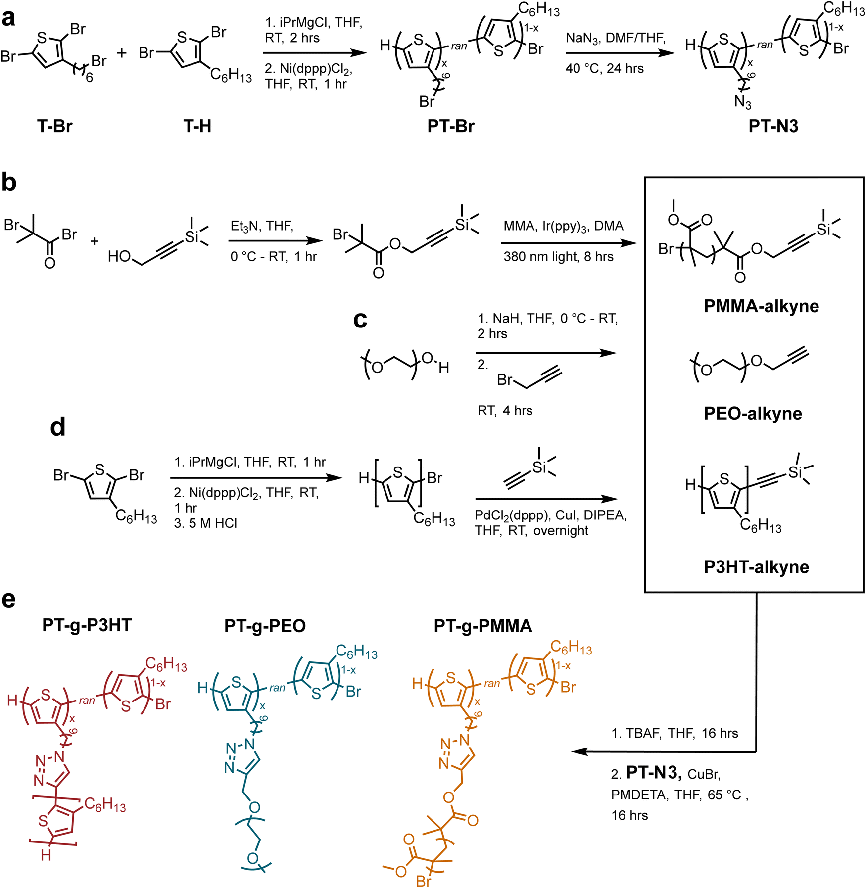 | ||
| Scheme 1 (a) Synthesis of polythiophene backbone through Kumada coupling and nucleophilic SN2 substitution (b) synthesis of PMMA side chains through light-mediated ATRP (c) synthesis of alkyne-terminated poly(ethylene oxide) through SN2 substitution (d) synthesis of P3HT side chains through Kumada coupling and alkyne addition with a Songashira coupling (e) grafting-to approach using CuAAC and graft polymer chemical structures. | ||
PT-Br was then treated with sodium azide in tetrahydrofuran (THF) at 50 °C overnight to produce poly(3-hexylthiophene-random-3-(6-azidohexyl)thiophene) (PT-N3). The product was purified by precipitation in methanol and rinsed with water to remove unreacted sodium azide. The post-polymerization modification was verified through 1H NMR and Fourier-transform infrared spectroscopy (FTIR) (Fig. S2 and S3a, ESI†). The presence of a new absorption band at 2200 cm−1 in the FTIR spectrum is due to the asymmetric stretching of the azide functional group and indicates successful polymer modification. 1H NMR experiments verified quantitative conversion from bromine to azide by an upfield shift of the methylene protons adjacent to the bromine (from δ = 3.44 to δ = 3.29 ppm). Gel permeation chromatography (GPC) further indicated successful modification without crosslinking due to the limited molecular weight increase (see Fig. S3b, ESI†).
Scheme 1(b–d) illustrates synthesis of alkyne-terminated PEO, P3HT, and PMMA side chains. P3HT was synthesized following reported methods and the polymerization reaction mixture was quenched with hydrochloric acid to produce ω-terminated P3HT with a bromine chain end.21,22 According to 1H NMR,23 the P3HT side chains indeed contain primarily monofunctionalized chains (–Br/H) (see Fig. S4, ESI†). The resulting P3HT-Br polymer was purified by precipitation in methanol, followed by Soxhlet extraction in methanol (12 h) and hexanes (12 h). The hexane P3HT fraction was then used in the following reaction, i.e., a Songashira coupling to modify the monofunctionalized P3HT through the addition of a protected alkyne. This functionalization was again confirmed by 1H NMR through appearance of trimethylsilyl protons (0.08 ppm) (see Fig. S5, ESI†). In addition, high resolution matrix-assisted laser desorption/ionization-time of flight (MALDI-ToF) was conducted to verify monofunctionalization of P3HT and avoid crosslinking in the subsequent CuAAC reactions (see Fig. S6, ESI†).
PEO and PMMA synthetic conditions were controlled to produce molecular weights that resemble the P3HT samples. Poly(ethylene oxide monomethyl ether) (Mw = 2100 g mol−1) was modified using propargyl bromide and the addition of the alkyne group was verified by 1H NMR (Fig. S7, ESI†). Alkyne-functionalized PMMA was synthesized using light-mediated atom transfer radical polymerization (ATRP) from an alkyne containing ATRP initiator following previously reported techniques.241H NMR and GPC were used to verify the terminal alkyne moiety and molecular weights (Fig. S8, ESI†). Table 1 summarizes the molecular weights of P3HT-alkyne, PEO-alkyne, and PMMA-alkyne side chains.
| Polymer | M n SEC (g mol−1) | M n,NMR (g mol−1) | Mol% side chains | Wt% side chains | Wt% aromatics | Grafting efficiency |
|---|---|---|---|---|---|---|
| P3HT-alkyne | 5800 | 2300 | 100 | 100 | 48.8 | — |
| PEO-alkyne | 2100 | 1500 | 100 | 100 | 0 | — |
| PMMA-alkyne | 1700 | 2900 | 100 | 100 | 0 | — |
| PT-g-P3HT | 29000 |
32400 |
90.6 | 76.9 | 39.0 | 48% |
| PT-g-PEO | 16300 |
46900 |
97.6 | 71.4 | 10.4 | 55% |
| PT-g-PMMA | 24400 |
34200 |
94.1 | 88.3 | 4.3 | 86% |
The final graft polymers were synthesized via CuAAC from the azide-functionalized PT-N3 and the individual alkyne-terminated side chains.20 PMMA and P3HT alkynes were deprotected using a tetrabutylammonium fluoride solution (TBAF) the day before (see Experimental information). The PT-N3 backbone was added to a THF solution containing the side chain polymers, and subsequently a solution of copper bromide (Cu(I)Br) and N,N,N′,N′′,N′′-pentamethyldiethylenetriamine (PMDETA) in THF was added. The reaction was stirred at 65 °C. Each graft polymer, i.e., poly(thiophene)-graft-poly(3-hexylthiophene) (PT-g-P3HT), poly(thiophene)-graft-poly(ethylene oxide) (PT-g-PEO), and poly(thiophene)-graft-poly(methyl methacrylate) (PT-g-PMMA) was purified by initial precipitation in methanol. PT-g-P3HT was then purified by Soxhlet extraction in methanol, acetone, and hexanes (12 hours per solvent). Because the P3HT side chains were soluble in hexanes, they were mostly extracted during this purification. PT-g-PMMA was Soxhlet-extracted in methanol, in which the PMMA side chains were soluble. PT-g-PEO was purified from unreacted side chains by rinsing with methanol, a good solvent for PEO, but not P3HT.
GPC elugrams verified an increase in molecular weight and successful grafting-to reactions that lead to conjugated grafted macromolecules. Graft polymers and side chains containing PMMA and PEO were analyzed with THF as the GPC eluant, while PT-g-P3HT and P3HT-alkyne were analyzed using a chlorobenzene eluant due to the better solubility of P3HT in chlorobenzene. GPC also helped confirm purification of the grafts from unreacted side chains (see Fig. 1). By comparing to the side chain chromatograms, the absence of unreacted PMMA and PEO side chains in PT-g-PMMA and PT-g-PEO, respectively, is apparent. The presence of a small shoulder in PT-g-P3HT, however, indicates minor unreacted P3HT side chain impurities. Table 1 summarizes the chemical composition of graft polymers.
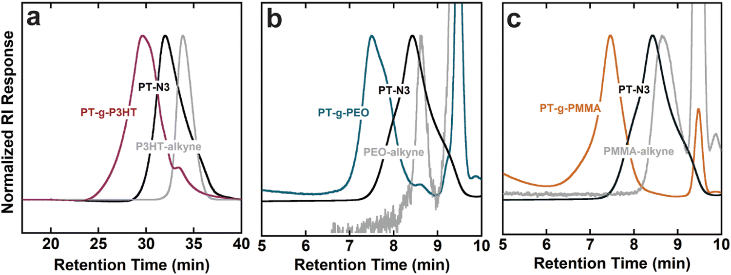 | ||
| Fig. 1 Normalized gel permeation chromatography (GPC) traces of graft polymers compared to backbone and side chains respectively: (a) PT-g-P3HT, PT-N3, P3HT-alkyne, PT-N3, (b) PT-g-P3HT, PT-N3, PEO (c) PT-g-PMMA, PT-N3, PMMA. | ||
GPC analyses using linear polystyrene standards are inherently skewed for graft polymers, whose more densely packed conformations yield smaller hydrodynamic radii compared to linear polymers. Therefore, 1H NMR was used to determine the mole percent of conjugated monomers in the backbone to that of side chain monomers and calculate the graft polymer molecular weight (Fig. S9–S11, ESI†). The mole percentages were then converted to weight percent of backbone to side chains. As expected, Mn was underestimated by the GPC analyses when compared to 1H NMR. Using Mn,NMR, the grafting efficiency of the click reaction was calculated from the amount of expected reactive sites on each backbone and the molar ratio of side chain monomer to backbone monomer (see Tables S1–S5, ESI†). The grafting efficiency of PT-g-P3HT corresponds well with literature for grafting conjugated side chains onto a conjugated backbone.20 In comparison, the efficiencies of PT-g-PEO and PT-g-PMMA are higher, which could be due to their smaller Kuhn length and smaller hydrodynamic radius.25 Because the grafting-to approach is mass transport limited (i.e., the side chains must diffuse through those already attached to the backbone to reach a reactive site), we speculate that smaller hydrodynamic radii allow for improved mobility of the PMMA and PEO side chains to the reactive sites on the PT-N3 backbone.
The steady-state UV-vis absorbance and photoluminescence spectra of the graft polymers in chloroform at room temperature were measured using UV-vis spectroscopy and fluorometry at different concentrations. Because of the copolymer nature of the graft polymers, we use mass absorptivity (ε) to describe light absorption properties instead of molar absorptivity. ε was calculated using Beer–Lambert's law from a linear fit of absorbance vs. concentration (Fig. S12–S18, ESI†). We also calculate the mass absorptivities of the grafts that is then normalized by the weight percent of aromatics (or chromophores) in the graft (see Table 2). Because all polymers contain exclusively thiophene as a chromophore, the absorption spectra are dominated by the first singlet state of polythiophene (Fig. S19, ESI†).26 In comparison to P3HT, both PT-Br and PT-N3 show lower ε (Fig. 2(a), left). The photoluminescence spectra (cts) were normalized to the quanta of light absorbed at the excitation wavelength (λ450nm); f = 1 − 10−A, where A is absorbance (Fig. 2(a), right). The photoluminescence spectrum is dominated by the radiative decay of the singlet exciton at around λ = 570 nm.26 The addition of an electron-withdrawing bromine end group to P3HT has been shown to reduce ε and photoluminescence intensity.27 Quantum yields (ϕ) were calculated from the linear fit of their integrated fluorescence to their absorbance in comparison to a standard, in this case 4-(dicyanomethylene)-2-methyl-6-(4-dimethylaminostyryl)-4H-pyran (Fig. S20–S23, ESI†). P3HT, PT-Br and PT-N3 show very similar photoluminescence spectra and ϕ ≈ 0.26, indicating the –H to –Br and –H to –N3 substitution does not influence the electronic structure of P3HT.
| Polymer | Max. mass absorptivity (mL mg−1 cm−1) at λmax (nm) | Normalizeda max. mass absorptivity (mL mg−1 cm−1) | Quantum yield at λmax (nm) |
|---|---|---|---|
| a Normalized by weight fraction of aromatic groups. | |||
| P3HT | 54.8 (447) | 112.0 | 0.25 (576) |
| PT-Br | 27.4 (444) | 72.1 | 0.27 (571) |
| PT-N3 | 35.8 (445) | 99.4 | 0.26 (571) |
| PT-g-P3HT | 25.4 (443) | 53.6 | 0.12 (574) |
| PT-g-PEO | 0.9 (440) | 28.1 | 0.06 (570) |
| PT-g-PMMA | 3.8 (439) | 100.0 | 0.18 (572) |
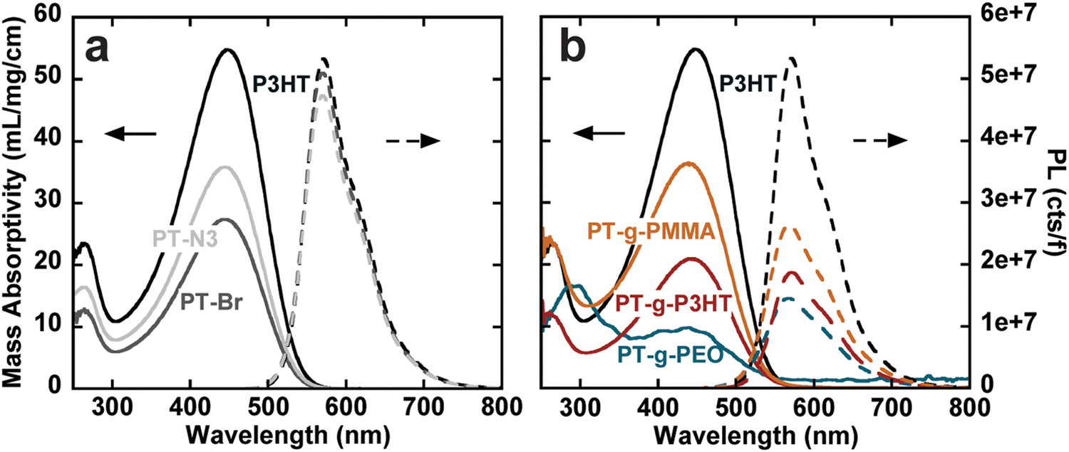 | ||
| Fig. 2 Mass absorptivity in mL mg−1 cm−1 (right) and photoluminescence normalized to the number of photons absorbed at the excitation wavelength (λ450nm) (left) for (a) P3HT, PT-Br, and PT-N3; and (b) P3HT, PT-g-P3HT, PT-g-PEO, PT-g-PMMA. | ||
PT-g-PEO, PT-g-PMMA, and PT-g-P3HT all show reduced mass absorbance and a lower photoluminescence intensity compared to linear P3HT (Fig. 2(b)). The values of ε and ϕ of the graft polymers decreased compared to linear P3HT (Table 2). This could in part be due to deviations of the backbone planarity with the addition of sterically hindered side groups leading to a decreased effective conjugated length of the graft polymer backbone. The absorption and emission of PT-g-PEO (ε = 28.1, ϕ = 0.06), however, decrease more than the other studied grafts. PEO can exhibit coil-to-globule transitions in organic solvents at 30 °C.28,29 At room temperature, we speculate the PEO side chains could be in a globular form inducing increased steric hindrance and further reducing the effective conjugation length of the polythiophene backbone compared to P3HT and PMMA side chains.
Conjugated polymer nanoparticles from the graft polymers were prepared in deionized water using a modified precipitation method (Fig. S24, ESI†).1,2,9 (PT-g-PMMA)NP and (PT-g-PEO)NP were prepared by dropwise addition of 10 mL water to 1 mg mL−1 and 2 mg mL−1 solutions in THF under vigorous stirring, respectively (see Fig. 3(a)). THF was then evaporated under a flow of argon. PT-Br, PT-N3, P3HT, and PT-g-P3HT did not form stable nanoparticles using the dropwise technique, instead forming large aggregates and precipitating out of solution. As an alternative, PT-Br, PT-N3, P3HT, and PT-g-P3HT were prepared into a 0.1 mg mL−1 solution of THF and 1 mL of this solution was added to 10 mL of water under ultrasonication (Fig. 3(b)). THF was then evaporated under argon flow. With this modified protocol for PT-Br, PT-N3, P3HT, and PT-g-P3HT, all polymers formed stable suspensions of nanoparticles in water and did not precipitate or settle on the sides or bottom of the vials over multiple days, as previously shown.4
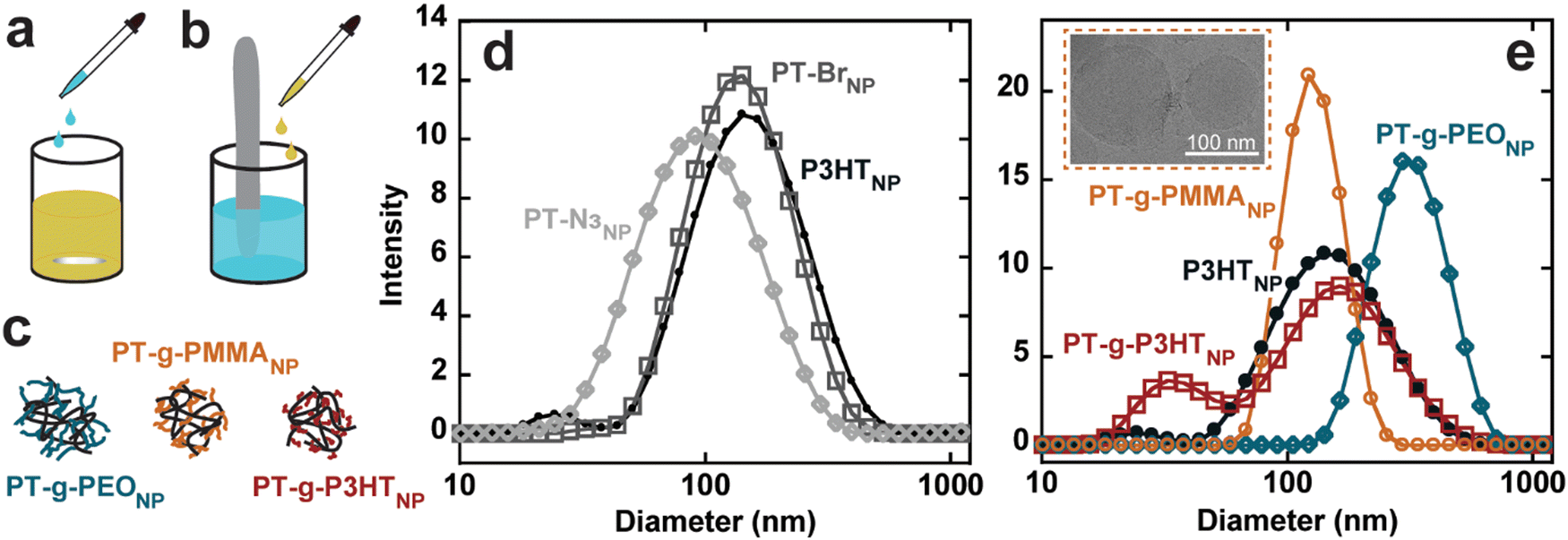 | ||
| Fig. 3 (a) Nanoparticle formation for (PT-g-PMMA)NP and (PT-g-PEO)NP by dropwise addition of water, (b) nanoparticle formation for (P3HT)NP, (PT-Br)NP, (PT-N3)NP, and (PT-g-P3HT)NP utilizing ultrasonication, (c) nanoparticle depiction of graft polymers, (d) DLS size distributions for (P3HT)NP, (PT-B)NP, (PT-N3)NP, (e) DLS size distribution for (P3HT)NP, (PT-g-PEO)NP, (PT-g-PMMA)NP, (PT-g-P3HT)NP (inset: Cryo-EM of (PT-g-PMMA)NP). | ||
Conjugated polymer nanoparticle size was measured using dynamic light scattering (DLS) with three independent measurements (Fig. S25, ESI†). The three measurements were averaged and overlayed, displaying similar diameters of the different nanoparticles from d = 80 to 120 nm (Fig. 3(d) and (e)). (PT-g-PEO)NP form significantly larger nanoparticles, which could be due to the extended conformation of water soluble PEO side chains. Additionally, cryogenic electron microscopy (Cryo-EM) results show (PT-g-PMMA)NP ranging from about 70 nm to 130 nm (Fig. 3(e) – inset), confirming the DLS experiments describing the nanoparticle size.
UV-vis absorbance and photoluminescence spectra of conjugated nanoparticles were measured using UV-vis spectroscopy and fluorometry at different concentrations. The normalized absorbance and photoluminescence spectra and photophysical properties (ε and ϕ) were calculated as outlined above and are quantitatively summarized in Table 3, along with the size and the polydispersity index (PDI) obtained from DLS (Fig. S26–S38, ESI†). The broad, featureless absorption in chloroform is associated with the a twisting of the polymer backbone from repulsive steric interactions between repeat units.30 In the solid state, however, intrachain and interchain interactions result in the formation of structured aggregates. Aggregates are most apparent in (P3HT)NP, (PT-Br)NP, and (PT-N3)NP, where their absorption spectra show bathochromic shifts towards lower energy wavelengths (Fig. S39, ESI†) and three distinct features are present (λ = 600, 550, 490 nm).7,31,32 The lowest energy absorption (λ = 600 nm) corresponds to the 0–0 transition related to J-aggregates. The 0–1 transition occurs at λ = 550 nm corresponding to H-aggregates. The J- and H-aggregates lead to reduced photoluminescence through non-radiative recombination pathways.33,34 The large reduction in quantum yields (from f = 0.260 to f = 0.001) for (P3HT)NP, (PT-Br)NP, and (PT-N3)NP can be attributed to the formation of these aggregates.
| Sample | Z-averaged size (nm) | PDI | ε max,normalized (mL mg−1 cm−1) at λmax (nm) | Quantum yield at λmax (nm) |
|---|---|---|---|---|
| (P3HT)NP | 120.0 | 0.29 | 65.2 (478) | 0.001 (562) |
| (PT-Br)NP | 124.6 | 0.18 | 108 (512) | 0.001 (646) |
| (PT-N3)NP | 81.7 | 0.27 | 92.3 (498) | 0.001 (636) |
| (PT-g-P3HT)NP | 95.6 | 0.49 | 31.8 (463) | 0.005 (566) |
| (PT-g-PEO)NP | 335.4 | 0.27 | 16.1 (429) | 0.019 (582) |
| (PT-g-PMMA)NP | 123.3 | 0.05 | 8.0 (459) | 0.247 (570) |
The absorption spectra of (PT-g-P3HT)NP is red-shifted and shows similar aggregation structures as (P3HT)NP; however, the 0–0 transition at λ = 600 nm was reduced in the normalized spectra (Fig. 4(a)). This could indicate the reduction of aggregate formation and be the reason for an improvement in the quantum yield (ϕ = 0.005). It has been suggested that low molecular weight P3HT contains more photophysically uncoupled polymer chains than its high molecular weight counterpart.35,36 Therefore, by grafting smaller P3HT side chains to a long backbone, the chain–chain coupling effects are diluted and could also contribute to an improved quantum yield. Additionally, since P3HT and PT-g-P3HT share the same monomer structure, the improved quantum yield of PT-g-P3HT can be directly attributed to the difference in architecture.
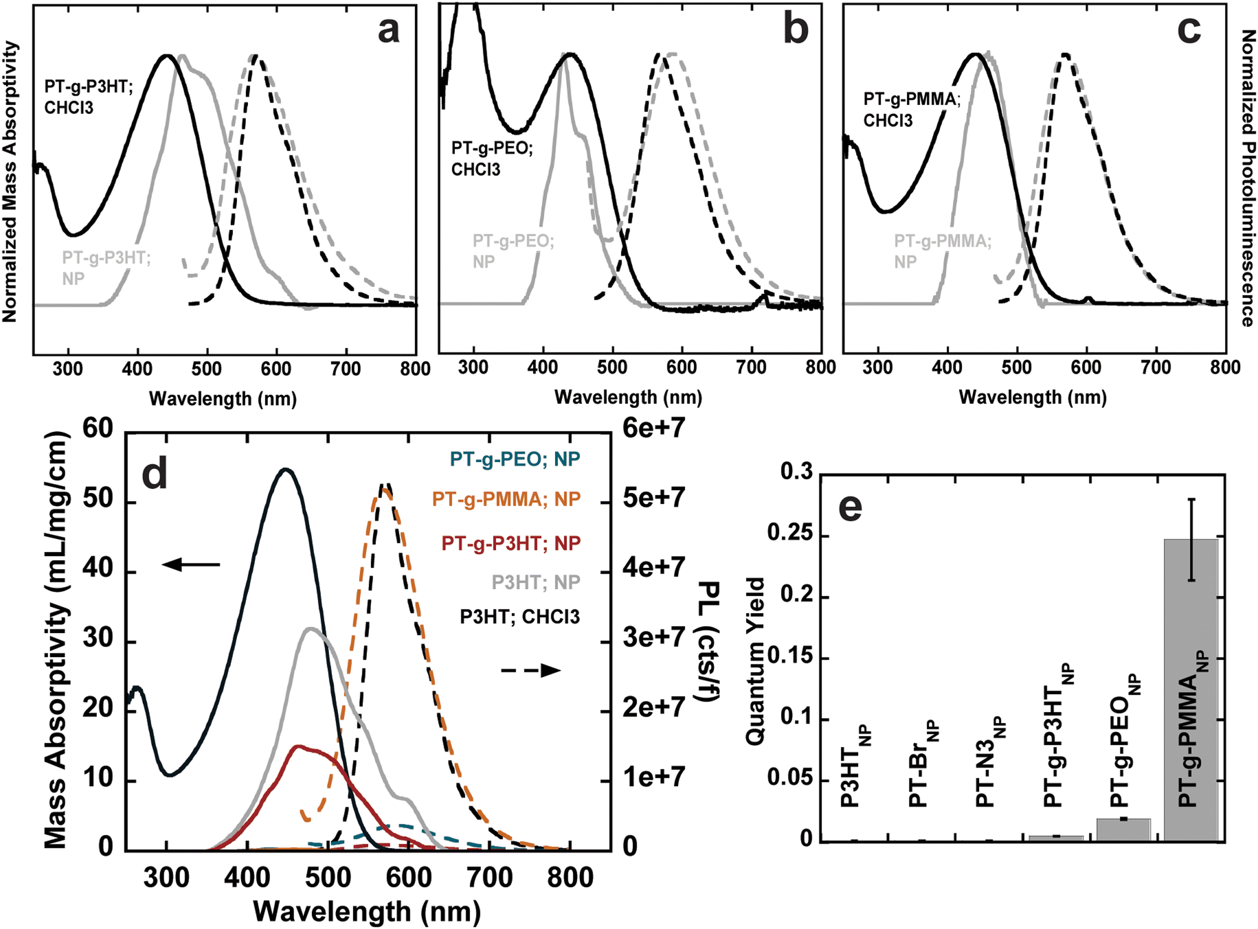 | ||
| Fig. 4 Normalized absorbance and emission spectra for (a) (PT-g-P3HT)CHCl3 (black), (PT-g-P3HT)NP (grey), (b) (PT-g-PEO)CHCl3 (black), (PT-g-PEO)NP (grey), (c) (PT-g-PMMA)CHCl3 (black), (PT-g-PMMA)NP (grey); (d) mass absorptivity and normalized PL spectra of P3HT, (P3HT)NP, (PT-g-PEO)NP, (PT-g-P3HT)NP, (PT-g-PMMA)NP; (e) quantum yield of the conjugated nanoparticles, error bars were obtained from the standard error of the slope from the linear fit of absorbance vs. integrated fluorescence. | ||
In contrast, the absorption spectra of (PT-g-PMMA)NP do not show signatures of aggregation (Fig. 4(c)). In fact, the absorbance of (PT-g-PMMA)NP resembles that of P3HT in chloroform, suggesting the PT backbone is trapped in an isolated or “solution-like” state (solvated by the PMMA side chains) when in nanoparticle form.37 The quantum yield of (PT-g-PMMA)NP (ϕ = 0.247) is higher by a factor of about 250 when compared to (P3HT)NP, which can be attributed to the reduced aggregation (Fig. 4(d)). The quantum yield is close to that of P3HT in chloroform, when completely unaggregated (Fig. 4(e)). The solid-state absorption of PT-g-PMMA further confirms the isolation of the PT backbone by the relatively unchanged peak absorption wavelength (λ ≈ 450 nm) compared to absorption in solution and as nanoparticles (Fig. S40, ESI†). Solid-state photoluminescence measurements that have been normalized by the number of photons absorbed also show a large increase to the photoluminescence of (PT-g-PMMA)NP compared to (P3HT)NP (Fig. S41, ESI†). The solid-state absorbance and photoluminescence indicate these materials could be useful not only as nanoparticles, but also as photoluminescent thin-films and devices. In addition, we speculate that the similarity of the absorption spectra and quantum yield between solubilitzed P3HT and (PT-g-PMMA)NP suggests that the grafting density (86% of backbone sites) is high enough to effectively isolate individual polythiophene backbones. Further work is needed to identify the minimum grafting density needed to enhance the photoluminescence of polythiophene in nanoparticles and films.
The absorption spectra for (PT-g-PEO)NP show new features at higher energy not corresponding to J- and H-aggregation. The new features (λ = 450, 415, 405) could be caused by the increased crystallinity of the PEO side chains, which could disrupt the conjugated backbone and make the monomers act essentially as individual chromophores (Fig. 4(b)). Thermal analysis by differential scanning calorimetry shows PT-g-PEO exhibits a crystallization temperature at 32.9 °C, providing evidence that there could be crystalline PEO domains in (PT-g-PEO)NP at room temperature (Fig. S42b and Table S6, ESI†). Nevertheless, the reduction of aggregation in the thiophene backbone still serves to improve the quantum yield (ϕ = 0.019). Additionally, just as (PT-g-PMMA)NP exhibits reduced aggregation and improved photoluminescence in the solid-state, so does (PT-g-PEO)NP (Fig. S40 and S41, ESI†).
Conclusion
We demonstrate a versatile method to modify conjugated polymers through side chain engineering. Leveraging a grafting-to approach, different alkylated side chains with a conjugated backbone were synthesized: poly(thiophene)-graft-poly(3-hexylthiophene), poly(thiophene)-graft-poly(ethylene oxide), and poly(thiophene)-graft-poly(methyl methacrylate). P3HT side chains were selected to produce a fully conjugated graft homopolymer, thereby directly relating the architectural change (from linear to grafted) to changes in the optoelectronic properties. The scope of grafted conjugated polymers was expanded through the addition of non-conjugated PEO or PMMA side chains. These polymers were fabricated into nanoparticles through two modified nanoprecipitation methods. Linear P3HT, PT-Br and PT-N3 show aggregation in their absorbance spectrums leading to small quantum yields. In contrast, each graft polymer we synthesized shows improved quantum yields. By changing the architecture of P3HT from linear into a grafted architecture, aggregation was reduced. This was found to result in a quantum yield increase in the emission from conjugated nanoparticles by a factor of about 250. Overall, this work shows that graft copolymer architectures can enhance fluorescence emission of polymer nanoparticles that could enable them as viable materials for applications in various sensors, therapeutics, and imaging.Experimental information
For a detailed list of chemicals refer to the ESI.†PT-N3 was synthesized according to a literature procedure.20 P3HT-alkyne, PMMA-alkyne, and PEO-alkyne were also synthesized according to literature procedures.20,38,39
General synthesis of graft polymers
An oven dried 20 mL vial was charged with a stir bar and PMMA-alkyne or P3HT-alkyne. The polymers were dissolved in THF and tetrabutylammonium fluoride solution 1.0 M in THF (TBAF) was added. The mixtures were stirred overnight at room temperature to deprotect the alkynes. This step was skipped for PEO-alkyne polymers. The azide containing backbones were added to the polymer mixture, then 10 equivalent of a CuBr/PMDETA catalyst solution was added to the mixture. The reaction was stirred at 50 °C overnight. The polymers were then precipitated in methanol/water mixtures.Synthesis of PT-g-PEO
120 mg of PEO-alkyne (Mn = 1500 g mol−1) was added to a 20 mL oven dried vial and dissolved in 10 mL THF. 19.2 mg PT-N3 (Mn = 6900 g mol−1) was added to the vial and 123 mL of the catalyst solution (60 mg CuBr, 87 mL PMDETA, 2 mL THF) was added. The reaction was stirred overnight at room temperature. The product was precipitated in methanol:water 1:1.
Synthesis of PT-g-PMMA
100 mg of PMMA-alkyne (Mn = 2900 g mol−1) was added to a 20 mL oven dried vial and dissolved in 10 mL THF. 0.4 mL 1 M TBAF was added to the mixture and stirred overnight at room temperature. 19.2 mg PT-N3 (Mn = 6900 g mol−1) was added to the vial and 123 mL of the catalyst solution was added. The reaction was stirred overnight at room temperature. The product was precipitated in pure methanol and purified by Soxlet extraction in methanol for 12 hours.Synthesis of PT-g-P3HT
100 mg of P3HT-alkyne (Mn = 2300 g mol−1) was added to a 20 mL oven dried vial and dissolved in 10 mL THF. 0.5 mL 1 M TBAF was added to the mixture and stirred overnight at room temperature. 19.2 mg PT-N3 (Mn = 6900 g mol−1) was added to the vial and 123 mL of the catalyst solution was added. The reaction was stirred overnight at room temperature. The product was precipitated in methanol and purified by Soxlet extraction in methanol, acetone, and hexanes for 12 hours each.Nanoparticle preparation
Conjugated nanoparticles were prepared in DI water using a modified nanoprecipitation method.21 (PT-g-PMMA)NP and (PT-g-PEO)NP nanoparticles were prepared by dropwise addition of 5 mL water to 1 and 2 mg mL−1 solution in THF, respectively. The concentrations become 0.2 and 0.4 mg mL−1, respectively. The THF was then allowed to evaporate under argon flow. An Branson Sonifier 450 ultrasonicator at 20 Watts (was used to process all other polymers: (P3HT)NP, (PT-Br)NP, (PT-N3)NP, (PT-g-P3HT)NP. 0.1 mg mL−1) solutions were prepared in THF before 1 mL of this solution was added to 10 mL of water under ultrasonication. Subsequently, the THF was allowed to evaporate under argon flow. The final solution concentrations were 0.01 mg mL−1.Measurements
Liquid-state 1H NMR spectra were recorded on a Bruker AVIII-HD-500 MHz spectrometer in deuterated chloroform (CDCl3). 1H NMR was used to determine Mnvia end-group analysis and monomer molar ratio as needed. Specified GPC elugrams were obtained on a TOSOH EcoSEC Elite High-performance system running THF as the eluant at a flow rate of 1.0 mL min−1 and using a TSKgel H Type column as the solid phase. SEC molar mass distributions were determined relative to polystyrene standards. GPC was also performed on an Agilent 1260 system with an Agilent PLgel-MIXED-LC column running chlorobenzene as the eluant. The Agilent system was equipped with a refractive index detector (RID), viscometer (VS), light scattering detector (LS), and multiwavelength detector (MWD). Chlorobenzene was run at 0.5 mL min−1 and the detectors were calibrated with linear polystyrene standards (Agilent EasiVial PS-M). UV-vis spectroscopy was measured on an Agilent Technologies Cary 60 UV-Vis spectrophotometer. Steady-state fluorescent emission spectra were measured at an excitation wavelength of λex = 450 nm on a Photon Technology International QuantaMaster 300 fluorimeter equipped with a Xe arc lamp and a 914 photomultiplier detection system. Quantum yields were measured by calculating the linear slope of integrated fluorescence to absorbance and comparison to a standard of known quantum yield, 4-(dicyanomethylene)-2-methyl-6-(4-dimethylaminostyryl)-4H-pyran (ϕ = 0.35 in chloroform).40 Nanoparticle sizes were measured using dynamic light scattering (DLS) of the nanoparticle solution at their current concentrations. DLS was performed on a Malvern Zetasizer Nano ZS equipped with a 4 mW diode laser (λ = 632.8 nm). The size was obtained by measuring the Brownian motion of the particles, fitting the autocorrelation function and using the Stokes–Einstein equation. PDI, a measure of the average uniformity of the nanoparticles, was obtained as the square of the standard deviation divided by the z-averaged diameter of the nanoparticles. Because (PT-g-PMMA)NP shows some evidence of aggregation after multiple days, the size of (PT-g-PMMA)NP was measured on a separate batch as the rest of the studies presented here, to allow for the use of a fresh solution and ensure minimal aggregation. Cryo-EM images of nanoparticles were acquired by vitrification of a 0.2 mg mL−1 PT-g-PMMA solution on Quantifoil Holey Carbon Grids, 300 mesh, with 1.2 μm hole size and 1.3 μm spacings (Quantifoil MicroTools, Jena, Germany). The grids were glow discharged in a plasma cleaner for about five minutes before vitrification. An FEI Vitrobot (FEI Company, Hillsboro, OR) was used for the vitrification of the PT-g-PMMA solution. After blotting the grids with mounted papers for 3 seconds, the grids were plunged into cryogenic ethane. The samples were preserved in vitreous ice in liquid nitrogen before acquiring the Cryo-EM images. High-resolution cryogenic transmission electron microscopy was performed on the FEI Talos Arctica G2 at the Huck Institute of Life Sciences at Pennsylvania State University. The measurements were conducted using a 200 kV electron source and a Falcone 3ec direct electron detector in linear mode. Binning of 1 (no camera pixel binning) was used for the images with 4096 × 4096 pixels.Conflicts of interest
There are no conflicts of interest to declare.Acknowledgements
Funding support is acknowledged from the National Science Foundation (Award DMR-1921854) and the Pennsylvania State University. The authors would like to thank Matthew Billups and Andrew Zydney for training and use of the DLS. We thank Michael Geitner for preliminary TEM measurements. The authors thank Tapas Mal for NMR training. We also thank the Proteomics & Mass Spectroscopy Core Facility and Tania Laremore for help with MALDI-ToF measurements.References
- L. R. MacFarlane, H. Shaikh, J. D. Garcia-Hernandez, M. Vespa, T. Fukui and I. Manners, Nat. Rev. Mater., 2021, 6, 7–26 CrossRef CAS.
- A. Caires, T. Lima and T. Fedatto Abelha, Mater. Adv., 2023, 1, 525–553 Search PubMed.
- T. F. Abelha, C. A. Dreiss, M. A. Green, L. A. Dailey and T. F. Abelha, J. Mater. Chem. B, 2020, 8, 592–606 RSC.
- J. Pecher and S. Mecking, Chem. Rev., 2010, 110, 6260–6279 CrossRef CAS PubMed.
- S. Samitsu, T. Shimomura, S. Heike, T. Hashizume and K. Ito, Macromolecules, 2008, 8000–8010 CrossRef CAS.
- M. Jaymand, M. Hatamzadeh and Y. Omidi, Prog. Polym. Sci., 2015, 47, 26–69 CrossRef CAS.
- E. T. Niles, J. D. Roehling, H. Yamagata, A. J. Wise, F. C. Spano, A. J. Moule and J. K. Grey, J. Phys. Chem. Lett., 2012, 0–4 Search PubMed.
- Z. Hu, T. Adachi, R. Haws, B. Shuang, R. J. Ono, C. W. Bielawski, C. F. Landes, P. J. Rossky and D. A. Vanden Bout, J. Am. Chem. Soc., 2014, 136, 16023–16031 CrossRef CAS PubMed.
- N. A. Yoshioka, T. A. Faraco, H. S. Barud, S. J. L. Ribeiro, M. Cremona, B. Fragneaud, I. O. Maciel, W. G. Quirino and C. Legnani, Polymers, 2022, 14, 1–11 CrossRef PubMed.
- R. Li Fu, J. Hao Chu, H. Jiang and X. Sun, Chin. Phys. Lett., 1999, 16, 764–766 CrossRef.
- A. Haugeneder, U. Lemmer and U. Scherf, Chem. Phys. Lett., 2002, 351, 354–358 CrossRef CAS.
- P. Parkinson, C. Müler, N. Stingelin, M. B. Johnston and L. M. Herz, J. Phys. Chem. Lett., 2010, 1, 2788–2792 CrossRef CAS.
- P. J. Costanzo, K. K. Stokes and R. D. McCullough, Macromolecules, 2002, 35, 6804–6810 CrossRef CAS.
- B. K. Pu, K. Li and B. Liu, Adv. Funct. Mater., 2010, 20, 2770–2777 CrossRef.
- Y. Kim, H. J. Kim, J. Kim, R. C. Hayward and B. J. Kim, ACS Appl. Mater. Interfaces, 2017, 9, 2933–2941 CrossRef CAS PubMed.
- C. N. Kempf, K. A. Smith, S. L. Pesek, X. Li and R. Verduzco, Polym. Chem., 2013, 4, 2158–2163 RSC.
- A. Kreyes, A. Mourran, Z. Hong, J. Wang, M. Möller, F. Gholamrezaie, W. S. C. Roelofs, D. M. De Leeuw and U. Ziener, Chem. Mater., 2013, 25, 2128–2136 CrossRef CAS.
- L. T. Strover, J. Malmström and J. Travas-Sejdic, Chem. Rec., 2016, 16, 393–418 CrossRef CAS PubMed.
- D. F. Zeigler, K. A. Mazzio and C. K. Luscombe, Macromolecules, 2014, 47, 5019–5028 CrossRef CAS.
- N. K. Obhi, D. M. Peda, E. L. Kynaston and D. S. Seferos, Macromolecules, 2018, 51, 2969–2978 CrossRef CAS.
- R. H. Lohwasser and M. Thelakkat, Macromolecules, 2011, 44, 3388–3397 CrossRef CAS.
- G. Zhang, O. Yoshihiro and T. Yokozawa, Macromol. Rapid Commun., 2018, 1700586 CrossRef PubMed.
- D. S. Dissanayake, E. Sheina, M. C. Biewer, R. D. McCullough and M. C. Stefan, J. Polym. Sci., Part A: Polym. Chem., 2017, 55, 79–82 CrossRef CAS.
- J. A. Opsteen and J. C. M. Van Hest, Chem. Commun., 2005, 57–59 RSC.
- H. Gao and K. Matyjaszewski, J. Am. Chem. Soc., 2007, 129, 6633–6639 CrossRef CAS PubMed.
- J. Rühe, N. F. Colaneri, D. D. C. Bradley, R. H. Friend and G. Wegner, J. Phys.: Condens. Matter, 1990, 2, 5465–5477 CrossRef.
- Y. Kim, S. Cook, J. Kirkpatrick, J. Nelson, J. R. Durrant, D. D. C. Bradley, M. Giles, M. Heeney, R. Hamilton and I. McCulloch, J. Phys. Chem. C, 2007, 111, 8137–8141 CrossRef CAS.
- J. P. S. Farinha, S. Piçarra, K. Miesel and J. M. G. Martinho, J. Phys. Chem. B, 2001, 105, 10536–10545 CrossRef CAS.
- M. S. Khan, J. Appl. Polym. Sci., 2006, 102, 2578–2583 CrossRef CAS.
- A. Zen, J. Pflaum, S. Hirschmann, W. Zhuang, F. Jaiser, U. Asawapirom, J. P. Rabe, U. Scherf and D. Neher, Adv. Funct. Mater., 2004, 14, 757–764 CrossRef CAS.
- C. E. Johnson and D. S. Boucher, J. Polym. Sci., Part B: Polym. Phys., 2014, 52, 526–538 CrossRef CAS.
- C. Scharsich, R. H. Lohwasser, M. Sommer, U. Asawapirom, U. Scherf, M. Thelakkat, D. Neher and A. Kohler, J. Polym. Sci., Part B: Polym. Phys., 2012, 50, 442–453 CrossRef CAS.
- S. Cook, A. Furube and R. Katoh, Energy Environ. Sci., 2008, 1, 294–299 RSC.
- J. Clark, C. Silva, R. H. Friend and F. C. Spano, Phys. Rev. Lett., 2007, 98, 1–4 Search PubMed.
- F. Paquin, H. Yamagata, N. J. Hestand, M. Sakowicz, N. Bérubé, M. Côté, L. X. Reynolds, S. A. Haque, N. Stingelin, F. C. Spano and C. Silva, Phys. Rev. B: Condens. Matter Mater. Phys., 2013, 88, 12–14 CrossRef.
- A. G. Dixon, R. Visvanathan, N. A. Clark, N. Stingelin, N. Kopidakis and S. E. Shaheen, J. Polym. Sci., Part B: Polym. Phys., 2018, 56, 31–35 CrossRef CAS.
- O. Inganäs, W. R. Salaneck, J. E. Österholm and J. Laakso, Synth. Met., 1988, 22, 395–406 CrossRef.
- C. Beaumont, S. Naqvi and M. Leclerc, Trends Chem., 2022, 4, 714–725 CrossRef CAS.
- B. P. Fors and C. J. Hawker, Angew. Chem., Int. Ed., 2012, 51, 8850–8853 CrossRef CAS PubMed.
- R. K. Kanaparthi, S. Saha, M. Singh and A. M, IntechOpen, 2020, 1–27, DOI:10.5772/intechopen.93149.
Footnote |
| † Electronic supplementary information (ESI) available. See DOI: https://doi.org/10.1039/d3ma00165b |
| This journal is © The Royal Society of Chemistry 2023 |