DOI:
10.1039/D3MA00022B
(Review Article)
Mater. Adv., 2023,
4, 2524-2543
Recent advancements in 3D porous graphene-based electrode materials for electrochemical energy storage applications
Received
12th January 2023
, Accepted 7th April 2023
First published on 12th April 2023
Abstract
Graphene, being a two-dimensional all-aromatic sheet bonded with sp2 carbon atoms, has attracted much attention due to its excellent physicochemical properties like a large surface area, good electrical conductivity, and high thermal and chemical stability. Since the discovery of graphene, various efforts have been made to modify its structural properties for integrating this novel material in various electronic devices, fuel cells, and other energy storage applications. Furthermore, modification leads to the production of different graphene-based nanomaterials and one of the derivatives of a graphitic material is porous graphene. The advantage of using porous graphene in energy systems is that it has the properties of both porous material and graphene. In this connection, various synthesis conditions, dopants, and surface defects all significantly contribute to enhance the electrochemical performance of porous graphene. In this review, the recent advancements in 3D porous graphene-based electrode materials and their structural properties in relation to electrochemical energy storage systems are discussed.

Arthisree Devendran
| Ms Arthisree D. received her PhD from the Vellore Institute of Technology, Vellore, Tamil Nadu, India. Currently, she is a postdoctoral fellow at Next-Generation Energy Systems at Ensemble3, Center of Excellence in Warsaw, Poland. Her research interest focuses on the synthesis and designing of graphitic and covalent organic framework-based electrode materials for electrochemical energy storage applications. |

Atsushi Nagai
| Prof. Atsushi Nagai is a group leader of Next-Generation Energy Systems at Ensemble3 Center of Excellence in Warsaw, Poland. He obtained his PhD in the polymerization mechanism and polymerizable monomer design from Yamagata University, Japan, in 2005. He has more than 10 years of total professor experience as an assistant, visiting, and associate professors at Kyoto University (from 2008 to 2010), Institute for Molecular Science (IMS, from 2010 to 2017) University of Texas Southwestern (UTSW, from 2014 to 2015), Techinical University of Delft (TU Delft, from 2017 to 2020) and Toyohashi University of Technology (TUT, from 2021 to 2022), respectively. He has published more than 70 papers, 6 patents and 5 book chapters and edited 2 books as well as a textbook; “Conjugated Objects: Developments, Synthesis, and Applications” and as a handbook; “Covalent Organic Frameworks”. His research interest includes the design and synthesis of organic porous materials containing covalent organic frameworks and conjugated microporous polymers for various energy storage applications. |
1. Introduction
The fast depletion of fossil fuels and non-renewable resources has caused negative environmental impacts, leading to the search for eco-friendly and sustainable energy resources.1 Due to the increasing development of electronic devices, including laptops, mobile phones, smart gadgets, and electric vehicles, there has been a large amount of research interest in designing energy storage devices with high energy density, a fast-charging rate, and good cycling stability in the past few years.2,3 Nowadays, it is critical to developing novel materials that can provide more efficient and sustainable energy storage performance. Among them, supercapacitors and batteries are two types of electrochemical energy storage systems utilized for industrial device fabrication with complementary energy storage mechanisms.4,5 Various electrode materials used in batteries, fuel cells, and supercapacitors have certain problems like feeble electron/ion transport, poor thermal and electrochemical stability, and a lack of reproducibility because of their aging process.6,7 Interestingly, the electrodes based on porous materials have gained better capacitance activity because these porous frameworks allow ions to reach the surface easier and faster,8,9 leading to pore effects.
Graphene, being a unique two-dimensional (2D) material, has attracted attention of quite a large number of researchers in various fields since the time of its invention in 2004.10 The synthesis of graphene materials and graphene-based composites involves considerable strategies for energy-based applications. Owing to the large flat layered structure with strong sp2 covalent bonds, a high surface area, and excellent electron transport properties, graphene sheets are considered to be promising electrode materials for energy devices such as lithium batteries, supercapacitors, and many others.11,12 Graphene has a high theoretical surface area value of 2630 m2 g−1,13 and it possesses unique physicochemical properties like superior electrical conductivity, excellent chemical stability, and good thermal conductivity.14,15 Unfortunately, the chemically reduced graphene oxide (GO) suffers from re-stacking due to the inter-sheet van der Waals interactions between the graphene layers. This results in the significant degradation of its unique properties such as its large surface area, reduced transport channel, and ion diffusion.16,17 To fully understand the potentiality of graphene and overcome the re-stacking issue, much effort has been made into modifying its electronic and magnetic properties through doping with heteroatoms18 and hydrogenation.19 Meanwhile, graphene-based porous materials with a large number of pores and different pore structures have been prepared to improve their performance and broaden their application in various energy storage applications20–25 as illustrated in Fig. 1. Depending on the carbon source, the doping agents used for synthesis purposes and the surface alterations including the defective sites, the pores present in the resultant graphene sheets may range from atomic to nanoscale magnifications.20 Interestingly, the properties of porous graphene are distinct from those of ordinary graphene, such as their high surface area, better mechanical stability, abundantly exposed edges (3D structure), and ability to accelerate mass transfer (ions and molecules) not only on the surface but also throughout their porous framework, leading to their potential application in various fields.24–26 In particular, the porosity, specific surface area (SSA), and surface-to-volume ratio of the porous materials can be effectively fine-tuned by the preparation conditions20 and their investigations have focused on optimizing these dimensional properties over the past few years.25–27 Theoretical studies to analyse the electronic structure of porous graphene claim that its capacitance performances depends on the porous nature (including the number of pores), surface area, and active sites,20 which is in agreement with the experimental results. There are numerous studies on the formation of 2D and 3D porous graphene architectures.28–32 The 2D porous graphene sheets represent the holey graphene sheets where pores are distributed in their plane28 while the 3D porous graphene sheets possess an out-of-plane macroporous structure and they include graphene aerogel,29 graphene foam,30 graphene hydrogel,31 and graphene sponge.32 Overall, the unique properties of porous graphene nanomaterials make them a highly promising system for achieving improved electrochemical energy storage performance. However, there are a few issues that should be addressed to make porous graphene a multifunctional material for industrialization. In this review, we summarized the recent advancements in nanostructured 3D porous graphene-based electrode materials depending on their pore size and structural properties, with an emphasis on electrochemical energy storage systems like lithium-ion batteries (LIB), lithium–sulfur batteries (LSB), sodium-ion batteries (SIB) and supercapacitors (asymmetric and symmetric). We also discuss about some of the practical limitations of porous graphene nanomaterials in detail.
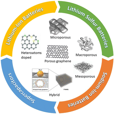 |
| | Fig. 1 Schematic illustration of different hierarchical porous graphene utilized for lithium-ion batteries, lithium–sulfur batteries, sodium-ion batteries, and supercapacitors. Porous structures are reprinted with permission from ref. 21 (micropore),22 (macropore),23 (mesopore),24 (hybrid),25 (heteroatoms doped). | |
2. Recent progress in porous graphene-based nanomaterials for electrochemical energy storage systems
According to industrial demands, the progress in designing battery materials is becoming more challenging day by day. There are numerous efforts made by researchers around the globe to find better electrode materials with superior electrochemical performances for energy storage applications. Nowadays, the utilization of carbonaceous materials, especially graphene, is becoming recommended in the development of energy devices such as batteries due to their high surface area, good mechanical strength, and chemical stability.10 However, graphene has a tendency to stack or aggregate together, whichever impairs its physicochemical properties such as surface area reduction and low electrochemical performance. Interestingly, synthesizing porous graphene with a 3D structure can effectively solve the above-mentioned difficulties, since they have hierarchal porous structures, which are very important for energy storage performances.33 In comparison to 2D basal plane graphitic structure, 3D (edge plane geometry) materials exhibit higher specific capacitance and high electron transport owing to their more exposed edges and oxygen-rich functional groups on the surface.33 Hence, the electrochemical performance is better in the 3D edge plane than in the 2D basal plane. By carefully tailoring the structure of hierarchal porous graphene, we can achieve more active sites that facilitate fast electron transfer reactions.
2.1 Recent progress in porous graphene-based lithium-ion batteries
Lithium-ion batteries (LIBs) have been the most desired energy storage devices in the past two decades. Their energy density is high (400 W h L−1) and is comparably higher than that of lead-acid (80 W h L−1), nickel-metal (300 W h L−1), and nickel-cadmium (150 W h L−1) batteries.34 Since 1991, researches have been focused on the improvement of LIB performances in terms of energy density, power density, and cycling stability.35 To enhance the electrochemical performance of any energy storage system, it is necessary to utilize active materials like metal oxides and other alloys that have high electrical conductivity, a high specific surface, and good cycling stability.10 Moreover, these active materials serve as an alternative to graphite anodes due to their high theoretical capacitance.34 Unfortunately, these metals and alloys suffer from poor cycling and rate performances due to their intrinsic resistance and the significant volume change that occurs during the long charge–discharge cycling process.34
To overcome these drawbacks, the active materials have to be combined with carbonaceous materials like graphene, carbon nanotubes, and other carbon derivatives.36,37 Recently, porous graphene has attracted much attention in battery research due to its superior electric conductivity, ionic conductivity, and surface properties.38 For example, a hierarchical porous 3D graphene nanomaterial (PHG) was prepared by the chemical vapor deposition (CVD) method using magnesium oxide (MgO) and methane (CH4) as starting materials. The synthesis process was carried out in a fluidized-bed reactor under an argon atmosphere. It is reported that MgO was chosen as a catalyst instead of any metal substrate because it is cost-effective and can easily control nanostructure and size by synthesis routes. However, by varying the reactor time (from 2, 5, 10, and 20 min), different batches of samples were prepared, and PHG-5 (5 min reactor time) was chosen as an optimal sample with better surface and electrical properties. It is noteworthy that the hierarchical porous structures of PHG were maintained even after the removal of MgO, as shown in Fig. 2(a–d).39 The BET surface area of pure MgO is 181.8 m2 g−1 and its corresponding pore size is around 3.2 nm in diameter, while the calculated BET surface area of the as-prepared PHG-5 (after the removal of MgO) is 1460.9 m2 g−1 and the pore size is around 4–5 nm. In contrast, the in situ formed porous graphene was prepared as an anode electrode material (refer Table 1) for lithium-ion battery performance, which is robust, has a stable cycling performance and delivers a specific capacitance of 1560 mA h g−1 at 0.1 A g−1 (Table 2), respectively. In addition, the same composite (PHG) was doped with sulfur and subjected to testing as cathode material (refer Table 1) for lithium–sulfur battery performance, which delivered a specific capacitance of around 1640 mA h g−1 at 0.1C and retained a capacitance of 95% over 80 cycles.39 The optimization of the porous graphene network in this work reported by Zhu et al. resulted in excellent charge storage capacity. In another study, Xie et al. have reported on nitrogen-doped porous hybrid graphene materials using calcium carbonate as a template source.40 The as-prepared porous graphene material was doped with iron nitrate, which is a starting material for nitrogen dopants, and waste coffee grains as carbon sources (refer to Fig. 3A). Moreover, three different compositions of the above-mentioned components were prepared in order to check the influence of carbonate and nitrogen on the physicochemical and electrochemical performance of porous graphene composites. A specific composition (NC 3320) was chosen as the best positive electrode material for LIB applications (Table 2). The as-prepared anode material could deliver a capacitance of 760 mA h g−1 at a current density of 100 mA g−1 after 100 cycles. The reported high-rate capacitance was around 330 mA h g−1 at a current density of 3200 mA g−1 as shown in Fig. 3B. The enhanced electrochemical performance of the optimal porous graphene composition is highly due to the large BET surface area of 531.3 m2 g−1, with an average pore dimension of 9.8 nm (for NC 3320) and its optimal surface properties (Fig. 3B and C).40 A recent study by Feng et al. reported a nitrogen and sulfur-doped porous graphene aerogel as an enhanced positive electrode (Table 1) material for high-performance LIBs. In this work, urea and thioacetamide were taken as starting materials for nitrogen and sulfur doping components, whereas graphene oxide and graphite are directly used as graphitic source materials. The self-assembled nitrogen- and sulfur-doped 3D porous graphene aerogel/natural graphite composite (N, S-PGA/NG) was prepared via a hydrothermal approach (Fig. 4A).41 The surface area of the as-prepared porous graphene aerogel/natural graphite (PGA/NG) was around 5.78 m2 g−1, which further increased to 13.75 m2 g−1 as a result of doping nitrogen and sulfur components in the PGA/NG system. However, N, S-PGA/NG could deliver an amount of capacitance around 531 mA h g−1 at 0.1C, and the rate performance is around 277 mA h g−1 at 2 C, whereas the individual graphene materials (PGA/NG) delivered a much lesser capacitance of 479 mA h g−1 at 0.1C, respectively. It is revealed that N, S-PGA/NG, and PGA/NG delivered a discharge capacitance of 474.7 and 388.9 mA h g−1 after 200 charge–discharge cycles at 0.5C as tabulated in Table 2. The better electrochemical performance and cycling stability of the as-prepared N, S-PGA/NG anode material is high due to the optimal doping of sulfur and nitrogen, which facilitates abundant pores and channels for efficient electron and ion transfer, as can be seen from Fig. 4B and C. Similarly, Mo et al. reported on high-performance LIBs using an in situ grown vertical graphene (VG) material anchored onto the microporous silicon (PMS) with encapsulated silver nanoparticle VG-PMS@Ag (Fig. 5A). The influence of graphene on enhancing the electrochemical performance of silicon materials for LIBs was studied in this work.42 Silicon is already a growing field in LIBs due to its high theoretical capacitance (4200 mA h g−1),43 but in practice, it has many drawbacks due to its low electrical and cycling performances. In this work,42 an attempt was made to overcome the above-mentioned drawback by designing this silicon-based electrode in such a way that it enhances the conductivity and cycling stability. The nanosilver encapsulated on the surface of porous micro-silicon (as in Fig. 5A and B) accelerates the charge transfer, which is beneficial for the electrochemical rate performance. The as-prepared VG-PMS@Ag positive electrode (refer to Table 1) exhibits an initial capacitance of 3121 mA h g−1 at 1 A g−1 and a high-rate capacitance value of 943.8 mA h g−1 at 6 A g−1, respectively. Even after 100 cycles, a reversible capacitance of 1403.9 mA h g−1 at 2 A g−1 was observed (refer to Fig. 5C and Table 2). The reported specific surface area of VG-PMS@Ag is 7.95 m2 g−1. This remarkable surface and electrochemical performance of the optimal composite may be due to the synergic interaction between the active sites of vertically grown graphene sheets, resulting in acting as an excellent electrical contact network on the domains of both electrode surface and silicon nanoparticles.
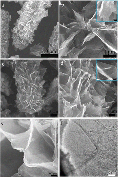 |
| | Fig. 2 (a and b) Low and high magnification SEM images of PHG/MgO nanocomposites, (c and d) low and high magnification SEM images of optimal PHG nanocomposites after removal of MgO, (e and f) SEM and TEM morphology of PHG nanocomposites. Reprinted with permission,39 Copyright [2019] American Chemical Society. | |
Table 1 Tabulation on coin cell construction of lithium-ion, lithium–sulfur, sodium-ion batteries and supercapacitors
| S. no |
Lithium-ion batteries |
| Battery type |
Positive |
Separator |
Negative |
Electrolyte |
Ref. |
| LiPF6-lithium hexafluorophosphate, LiTFSI-lithium bis(trifluoromethanesulfonyl)imide, EC-ethylene carbonate, DEC-diethylene carbonate, FEC-fluoroethylene carbonate, DOL-1,3 dioxolane, DME-dimethoxyethane, LiNO3-lithium nitrate, NMP-N-methyl-2-pyrrolidone, NaClO4-sodium perchlorate, EC-ethylene carbonate, PC-propylene carbonate, NaPF6-sodium hexafluorophosphate, EMIMBF4-1-ethyl-3-methylimidazolium tetrafluoroborate, H2SO4-sulfuric acid, MgSO4-magnesium sulfate, FeSO4-ferrous sulfate, KOH-potassium hydroxide. |
| 1. |
3D porous graphene nanosheet (PHG) |
PHG/carbon black/PVDF (85![[thin space (1/6-em)]](https://www.rsc.org/images/entities/char_2009.gif) : :![[thin space (1/6-em)]](https://www.rsc.org/images/entities/char_2009.gif) 5 5![[thin space (1/6-em)]](https://www.rsc.org/images/entities/char_2009.gif) : :![[thin space (1/6-em)]](https://www.rsc.org/images/entities/char_2009.gif) 10 wt%) 10 wt%) |
— |
Li/Li+ |
1 M LiPF6 mixed in EC/DME |
39
|
| (CR 2025) |
| 2. |
N-doped porous graphene |
N-doped porous graphene/ethylene black/PVDF (80![[thin space (1/6-em)]](https://www.rsc.org/images/entities/char_2009.gif) : :![[thin space (1/6-em)]](https://www.rsc.org/images/entities/char_2009.gif) 10 10![[thin space (1/6-em)]](https://www.rsc.org/images/entities/char_2009.gif) : :![[thin space (1/6-em)]](https://www.rsc.org/images/entities/char_2009.gif) 10 wt%) dissolved in NMP coated on a copper foil 10 wt%) dissolved in NMP coated on a copper foil |
Celgard 2300 |
Lithium foil |
1 M LiPF6 mixed in EC/DEC (50![[thin space (1/6-em)]](https://www.rsc.org/images/entities/char_2009.gif) : :![[thin space (1/6-em)]](https://www.rsc.org/images/entities/char_2009.gif) 50 v/v) 50 v/v) |
40
|
| (CR 2430) |
| 3. |
N, S-doped porous graphene |
N, S-doped porous graphene/acetylene black/PVDF (8![[thin space (1/6-em)]](https://www.rsc.org/images/entities/char_2009.gif) : :![[thin space (1/6-em)]](https://www.rsc.org/images/entities/char_2009.gif) 1 1![[thin space (1/6-em)]](https://www.rsc.org/images/entities/char_2009.gif) : :![[thin space (1/6-em)]](https://www.rsc.org/images/entities/char_2009.gif) 1) dissolved in NMP coated on copper foil 1) dissolved in NMP coated on copper foil |
Celgard 2400 |
Lithium foil |
1 M LiPF6 mixed in EC/DEC (1![[thin space (1/6-em)]](https://www.rsc.org/images/entities/char_2009.gif) : :![[thin space (1/6-em)]](https://www.rsc.org/images/entities/char_2009.gif) 1 v/v) 1 v/v) |
41
|
| (CR 2032) |
| 4. |
VG-PMS@Ag |
VG-PMS@Ag/super P/carboxyl methylcellulose, polymerized styrene-butadiene rubber (60![[thin space (1/6-em)]](https://www.rsc.org/images/entities/char_2009.gif) : :![[thin space (1/6-em)]](https://www.rsc.org/images/entities/char_2009.gif) 20 20![[thin space (1/6-em)]](https://www.rsc.org/images/entities/char_2009.gif) : :![[thin space (1/6-em)]](https://www.rsc.org/images/entities/char_2009.gif) 10 10![[thin space (1/6-em)]](https://www.rsc.org/images/entities/char_2009.gif) : :![[thin space (1/6-em)]](https://www.rsc.org/images/entities/char_2009.gif) 10) coated on a copper foil 10) coated on a copper foil |
Celgard 2325 |
Lithium metal |
1 M LiPF6 in a mixed EC/EMC (1![[thin space (1/6-em)]](https://www.rsc.org/images/entities/char_2009.gif) : :![[thin space (1/6-em)]](https://www.rsc.org/images/entities/char_2009.gif) 1 v/v) with 10 wt% of FEC and 1 wt% of vinylene carbonate 1 v/v) with 10 wt% of FEC and 1 wt% of vinylene carbonate |
42
|
| (CR 2032) |
| S. no |
Lithium–sulfur batteries |
| Battery type |
Positive |
Separator |
Negative |
Electrolyte |
Ref. |
| 5. |
3D porous graphene nanosheet (PHG-S) |
PHG-S/carbon black/PVDF(80![[thin space (1/6-em)]](https://www.rsc.org/images/entities/char_2009.gif) : :![[thin space (1/6-em)]](https://www.rsc.org/images/entities/char_2009.gif) 10 10![[thin space (1/6-em)]](https://www.rsc.org/images/entities/char_2009.gif) : :![[thin space (1/6-em)]](https://www.rsc.org/images/entities/char_2009.gif) 10) 10) |
— |
Li+/Li |
1 M LiTFSI/DOL/DME. |
39
|
| 6. |
3D porous N-graphene/S |
Composite/super P/PVDF (80![[thin space (1/6-em)]](https://www.rsc.org/images/entities/char_2009.gif) : :![[thin space (1/6-em)]](https://www.rsc.org/images/entities/char_2009.gif) 10 10![[thin space (1/6-em)]](https://www.rsc.org/images/entities/char_2009.gif) : :![[thin space (1/6-em)]](https://www.rsc.org/images/entities/char_2009.gif) 10) mixed in NMP on deposited on a carbon-coated aluminium foil 10) mixed in NMP on deposited on a carbon-coated aluminium foil |
— |
Lithium foil |
15 μL of 1 M (LiTFSI)/LiNO3/DME/DOL [1![[thin space (1/6-em)]](https://www.rsc.org/images/entities/char_2009.gif) : :![[thin space (1/6-em)]](https://www.rsc.org/images/entities/char_2009.gif) 1 v/v] with 1 mg sulfur 1 v/v] with 1 mg sulfur |
56
|
| (CR 2025) |
| 7. |
S@VN/N-rGO |
S@VN/N-rGO film immersed in Sulfur/carbon disulfide |
Celgard 2400 |
Metallic lithium |
1 M LiTFSI/DOL/1,2-dimethoxyethane DME (1![[thin space (1/6-em)]](https://www.rsc.org/images/entities/char_2009.gif) : :![[thin space (1/6-em)]](https://www.rsc.org/images/entities/char_2009.gif) 1 v/v) with an additive of 2% LiNO3 1 v/v) with an additive of 2% LiNO3 |
61
|
| (CR 2025) |
| 8. |
LPG-Ni/S |
LPG-Ni/S/super P/PVDF (8![[thin space (1/6-em)]](https://www.rsc.org/images/entities/char_2009.gif) : :![[thin space (1/6-em)]](https://www.rsc.org/images/entities/char_2009.gif) 1 1![[thin space (1/6-em)]](https://www.rsc.org/images/entities/char_2009.gif) : :![[thin space (1/6-em)]](https://www.rsc.org/images/entities/char_2009.gif) 1) mixed in a NMP coated on aluminium foil 1) mixed in a NMP coated on aluminium foil |
Celgard 2500 |
Lithium foil |
1 M LiTFSL and 0.1 M LiNO3 in (1![[thin space (1/6-em)]](https://www.rsc.org/images/entities/char_2009.gif) : :![[thin space (1/6-em)]](https://www.rsc.org/images/entities/char_2009.gif) 1 v/v) DOL/DME 1 v/v) DOL/DME |
63
|
| 9. |
GA-NiCo2O4/S |
GA-NiCo2O4/S/super P/PVDF (8![[thin space (1/6-em)]](https://www.rsc.org/images/entities/char_2009.gif) : :![[thin space (1/6-em)]](https://www.rsc.org/images/entities/char_2009.gif) 1 1![[thin space (1/6-em)]](https://www.rsc.org/images/entities/char_2009.gif) : :![[thin space (1/6-em)]](https://www.rsc.org/images/entities/char_2009.gif) 1) IN NMP coated on a Al-foil 1) IN NMP coated on a Al-foil |
Celgard 2400 |
Li-Metal |
1.0 M LiTFSL in DME/DOL (1![[thin space (1/6-em)]](https://www.rsc.org/images/entities/char_2009.gif) : :![[thin space (1/6-em)]](https://www.rsc.org/images/entities/char_2009.gif) 1 v/v) with 1 wt% of LiNO3 1 v/v) with 1 wt% of LiNO3 |
64
|
| (CR 2032) |
|
|
Sodium-ion batteries |
| S. no |
Battery type |
Positive |
Separator |
Negative |
Electrolyte |
Ref. |
| 10. |
N-3DPG |
N-3DPG/super P/sodium alginate (80![[thin space (1/6-em)]](https://www.rsc.org/images/entities/char_2009.gif) : :![[thin space (1/6-em)]](https://www.rsc.org/images/entities/char_2009.gif) 10 10![[thin space (1/6-em)]](https://www.rsc.org/images/entities/char_2009.gif) : :![[thin space (1/6-em)]](https://www.rsc.org/images/entities/char_2009.gif) 10) coated on a copper foil 10) coated on a copper foil |
Whatman glass microfibre membrane |
Sodium foil |
1 M L−1 NaClO4 in EC/PC (1![[thin space (1/6-em)]](https://www.rsc.org/images/entities/char_2009.gif) : :![[thin space (1/6-em)]](https://www.rsc.org/images/entities/char_2009.gif) 1 v/v) with non-reactive 5 wt% FEC additive 1 v/v) with non-reactive 5 wt% FEC additive |
72
|
| (CR 2032) |
| 11. |
FeS2C-RG |
FeS2C-RG/carbon black/PVDF (80![[thin space (1/6-em)]](https://www.rsc.org/images/entities/char_2009.gif) : :![[thin space (1/6-em)]](https://www.rsc.org/images/entities/char_2009.gif) 10 10![[thin space (1/6-em)]](https://www.rsc.org/images/entities/char_2009.gif) : :![[thin space (1/6-em)]](https://www.rsc.org/images/entities/char_2009.gif) 10) on Cu foam 10) on Cu foam |
Whatman glass microfibre membrane |
Sodium foil |
1 M NaCl4 in EC/DEC (1![[thin space (1/6-em)]](https://www.rsc.org/images/entities/char_2009.gif) : :![[thin space (1/6-em)]](https://www.rsc.org/images/entities/char_2009.gif) 1 v/v) 1 v/v) |
73
|
| 12. |
PVA-In2S3-graphene |
PVA-In2S3-graphene/carbon black/carboxymethylcellulose (60![[thin space (1/6-em)]](https://www.rsc.org/images/entities/char_2009.gif) : :![[thin space (1/6-em)]](https://www.rsc.org/images/entities/char_2009.gif) 20 20![[thin space (1/6-em)]](https://www.rsc.org/images/entities/char_2009.gif) : :![[thin space (1/6-em)]](https://www.rsc.org/images/entities/char_2009.gif) 20) 20) |
Whatman glass microfibre membrane |
Sodium metal |
1 M NaClO4 in EC/DEC/DMC (1![[thin space (1/6-em)]](https://www.rsc.org/images/entities/char_2009.gif) : :![[thin space (1/6-em)]](https://www.rsc.org/images/entities/char_2009.gif) 1 1![[thin space (1/6-em)]](https://www.rsc.org/images/entities/char_2009.gif) : :![[thin space (1/6-em)]](https://www.rsc.org/images/entities/char_2009.gif) 1 v/v) with 5 wt% FEC additive 1 v/v) with 5 wt% FEC additive |
77
|
| (CR 2032) |
| 13. |
a-Si@rGO |
a-Si@rGO/carbon black/sodium carboxymethyl cellulose (7![[thin space (1/6-em)]](https://www.rsc.org/images/entities/char_2009.gif) : :![[thin space (1/6-em)]](https://www.rsc.org/images/entities/char_2009.gif) 2 2![[thin space (1/6-em)]](https://www.rsc.org/images/entities/char_2009.gif) : :![[thin space (1/6-em)]](https://www.rsc.org/images/entities/char_2009.gif) 1) coated on copper foil 1) coated on copper foil |
Whatman glass microfibre membrane |
Sodium metal |
1 M NaPF6 in EC/DEC (1![[thin space (1/6-em)]](https://www.rsc.org/images/entities/char_2009.gif) : :![[thin space (1/6-em)]](https://www.rsc.org/images/entities/char_2009.gif) 1 v/v) with 2 wt% FEC 1 v/v) with 2 wt% FEC |
78
|
| S. no |
Supercapacitors |
| Active material |
Positive |
Separator |
Negative |
Electrolyte |
Ref. |
| 14. |
N-Graphene aerogel (UPGA) |
UPGA/acetylene black/PTFE coated on nickel foam (85![[thin space (1/6-em)]](https://www.rsc.org/images/entities/char_2009.gif) : :![[thin space (1/6-em)]](https://www.rsc.org/images/entities/char_2009.gif) 10 10![[thin space (1/6-em)]](https://www.rsc.org/images/entities/char_2009.gif) : :![[thin space (1/6-em)]](https://www.rsc.org/images/entities/char_2009.gif) 5) 5) |
Cellulose membrane |
UPGA/acetylene black/PTFE coated on nickel foam |
40 mL EMIMBF4 |
93
|
| 15. |
GO/PANI nanorods (GPGC) |
GPGC/Carbon black/PTFE (80![[thin space (1/6-em)]](https://www.rsc.org/images/entities/char_2009.gif) : :![[thin space (1/6-em)]](https://www.rsc.org/images/entities/char_2009.gif) 10 10![[thin space (1/6-em)]](https://www.rsc.org/images/entities/char_2009.gif) : :![[thin space (1/6-em)]](https://www.rsc.org/images/entities/char_2009.gif) 10) coated on a stainless steel 10) coated on a stainless steel |
Cellulose membrane |
GPGC/Carbon black/PTFE (80![[thin space (1/6-em)]](https://www.rsc.org/images/entities/char_2009.gif) : :![[thin space (1/6-em)]](https://www.rsc.org/images/entities/char_2009.gif) 10 10![[thin space (1/6-em)]](https://www.rsc.org/images/entities/char_2009.gif) : :![[thin space (1/6-em)]](https://www.rsc.org/images/entities/char_2009.gif) 10) coated on a stainless steel 10) coated on a stainless steel |
1 M H2So4 |
95
|
| 16. |
3D BPGC |
3D BPGC/PVDF (9![[thin space (1/6-em)]](https://www.rsc.org/images/entities/char_2009.gif) : :![[thin space (1/6-em)]](https://www.rsc.org/images/entities/char_2009.gif) 1) in NMP coated on a aluminium foil 1) in NMP coated on a aluminium foil |
— |
3D BPGC/PVDF (9![[thin space (1/6-em)]](https://www.rsc.org/images/entities/char_2009.gif) : :![[thin space (1/6-em)]](https://www.rsc.org/images/entities/char_2009.gif) 1) in NMP coated on aluminium foil 1) in NMP coated on aluminium foil |
2 M MgSO4 + 0.05 M FeSO4 |
96
|
| 17. |
Ni-TEGO |
Ni-TEGO coated onto a nickel foam disk |
Whatman glass fibre was used as a separator |
TEGO coated onto a nickel foam disk |
3.5 M KOH |
97
|
| (CR 2032) |
| 18. |
Porous graphene |
PGNH coated on copper foil |
KOH/PVA gel |
PGN/CNT |
1 M KOH |
98
|
Table 2 Tabulation on synthesis, surface area and electrochemical performance of porous graphene-based materials for lithium-ion battery, lithium sulfur and sodium ion batteries discussed in this manuscript
| S.no |
Porous graphene based electrode material |
Synthesis method |
SSA (m2 g−1) |
Capacitance |
Current density |
Cycling performance |
Ref. |
| Lithium-ion atteries |
| 1. |
3D porous graphene nanosheet (PHG) |
CVD |
1460.9 |
1560 mA h g−1 |
0.1 A g−1 |
— |
39
|
| 2. |
N-doped porous graphene |
Pyrolysis using template approach |
531.3 |
1523 mA h g−1 |
100 mA g−1 |
760 mA h g−1 at 100 mA g−1 after 100 cycles |
40
|
| 3. |
N, S-doped porous graphene |
Hydrothermal |
13.75 |
531 mA h g−1 |
0.1C |
474.7 mA h g−1 at 0.5C after 200 cycles |
41
|
| 4. |
VG-PMS@Ag |
CVD |
7.95 |
3121.6 mA h g−1 |
1 A g−1 |
1403.9 mA h g−1 at 2 A g−1 after 100 cycles |
42
|
| Lithium–sulfur batteries |
| 5. |
3D porous N-graphene/S |
Hydrothermal followed by pyrolysis |
432 |
1311 mA h g−1 |
0.2C |
714 mA h g−1 at 1.5 mA C m−2 after 400 cycles |
56
|
| 6. |
S@VN/N-rGO |
Template approach |
5.9 |
698 mA h g−1 |
1.0C |
577 mA h g−1 at 1.0C after 200 cycles |
61
|
| 7. |
LPG-Ni/S |
Hydrothermal followed by pyrolysis |
— |
718.7 mA h g−1 |
0.1C |
353.8 mA h cm−3 at 1 C after 1000 cycles |
63
|
| 8. |
GA- NiCo2O4 |
Hydrothermal followed by freeze drying |
82 |
1214.1 mA h g−1 |
0.1C |
444.2 mA h g−1 at 2 C after 1000 cycles |
64
|
| Sodium ion batteries |
| 9. |
N-3DPG |
Template approach using polystyrene |
224 |
285 mA h g−1 |
0.2 A g−1 |
310 mA h g−1 at 0.2 A g−1after 500 cycles |
72
|
| 10. |
FeS2-C/RG |
Hydrothermal followed by one-step vulcanization |
245.93 |
1196 mA h g−1 |
0.1 A g−1 |
291.7 mAh g −1 at 6 A g−1 after 1000 cycles |
73
|
| 11. |
PVA In2S3/r-G |
One pot hydrothermal approach |
193.5 |
565 mA h g−1 |
200 mA g−1 |
509 mAh g −1 at 200 mA g−1 after 100 cycles |
77
|
| 12. |
a-Si@rGO |
Sodiothermic reaction |
199 |
681.6 mA h g−1 |
100 mA g−1 |
142.1 mA h g−1 at 800 mA g−1 over 2000 cycle |
78
|
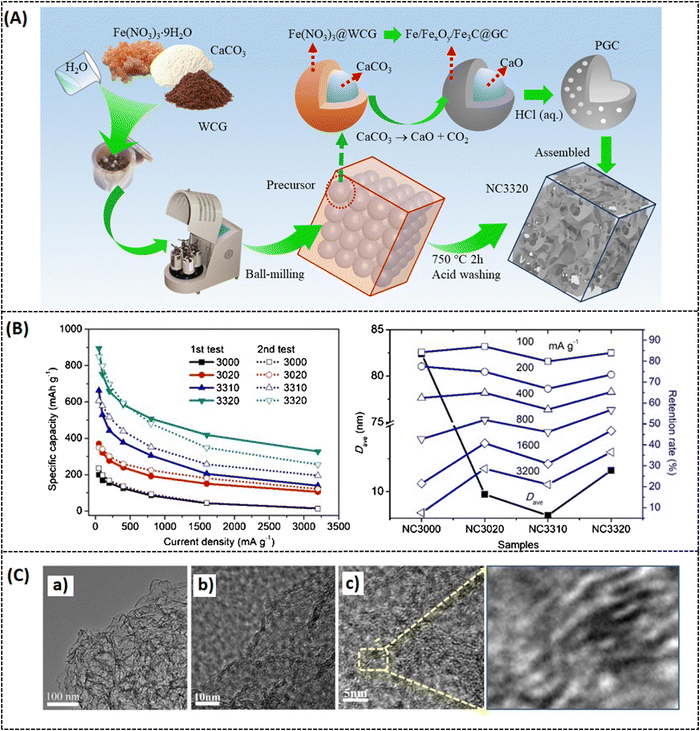 |
| | Fig. 3 (A) Schematic representation of porous carbon network, (B) capacitance at different current densities from 50 to 3200 mA g−1, (d) comparative response of retention rate vs. D average of different samples at various current densities, (C) TEM images of the optimal sample at different magnifications. Reprinted with permission,40 Copyright (2021) from Elsevier. | |
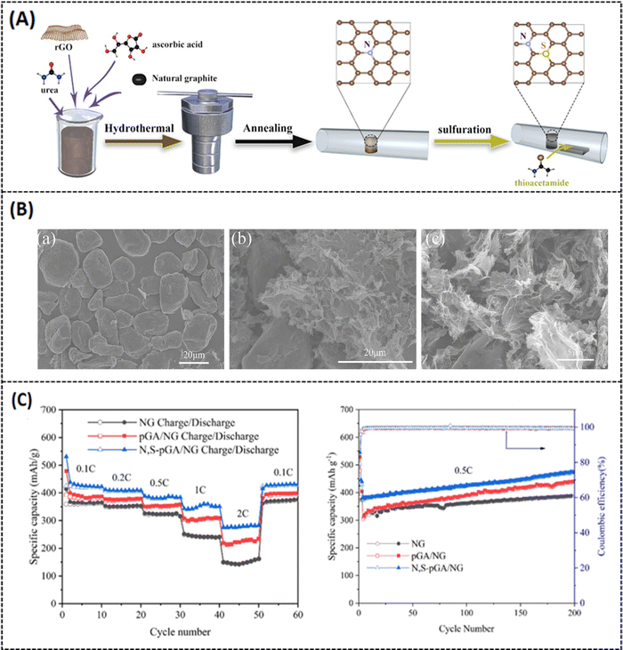 |
| | Fig. 4 (A) Schematic representation of N, S-PGA/NG, (B) (a–c) SEM images of pure graphene, PGA/NG and optimal N, S-PGA/NG, (C) rate performance at different current densities and cycling performance at 0.5C current density. Reprinted with permission,41 Copyright (2021) from Elsevier. | |
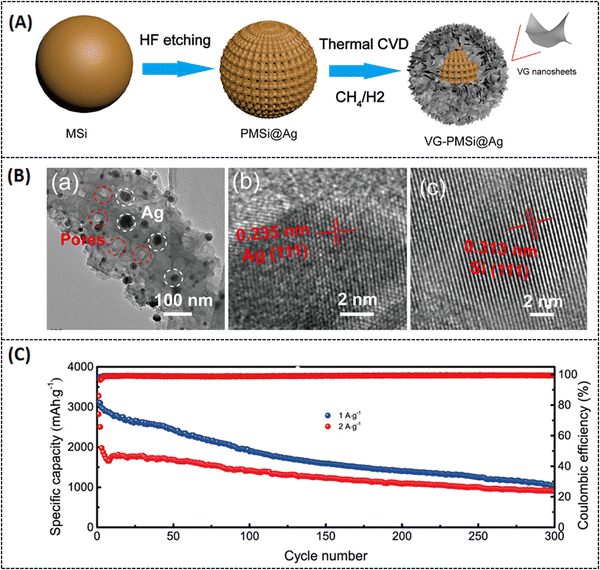 |
| | Fig. 5 (A) Schematic representation of the as-prepared VG-PMS@Ag, (B) (a–c) TEM images of the PMS@Ag composite, interplanar spacing of Ag in PMS@Ag, interplanar spacing of Silicon in PMS@Ag. (C) Long-term cycling activity of the VG-PMS@Ag electrode at different applied current densities. Reprinted with permission,42 Copyright [2022] American Chemical Society. | |
2.2 Recent progress in porous graphene-based lithium–sulfur batteries
Lithium–sulfur batteries (LSBs) are superior to conventional LIBs because they use sulfur as an additional component, which is abundant in nature, inexpensive, and less toxic.44 LSBs possess a high theoretical surface area of 1675 mA g−1 and an energy density of 2835 W h kg−1.45 However, they suffer from various drawbacks. First, sulfur and lithium sulfide are highly insulating materials; they have to be combined with some conducting additives in order to make them more active materials.46 Secondly, while constructing the battery system (LSB), some lithium polysulfides readily dissolve in the electrolyte medium and react with the lithium present at the anode, causing the “shuttle effect”.47,48 This leads to reduced capacitance performance and poor efficiency49 due to which commercializing LSBs is a challenging task.
Various strategies have been implemented to overcome this drawback, like encapsulating sulfur with a conducting substrate,50 adapting the separators,51 and varying the electrolyte medium.52 Among these strategies, utilizing porous carbon materials have been proven to effectively suppress polysulfide formation with modified synthesis routes.53,54 In this context, porous graphene is one of the most promising systems because it can not only offer high conductivity and surface area but also effectively enhance the charge/discharge volume exchange.55 Cheng et al. reported on a 3D nitrogen-doped porous graphene (3D-PNG/S) hydrothermally prepared (Fig. 6A) for LSB applications. In this report, urea is chosen as a precursor for nitrogen sources, and it also serves as a self-removal template for optimizing the surface pore dimension. The hydrothermally prepared N-doped porous graphene possesses (3D-PNG) more 3D interlinked porous structure as-like the conventional pure 3D reduced graphene oxide (rGO), which can be seen from morphological images in Fig. 6B.56 The measured specific surface area for 3D-PNG is around 432 m2 g−1 which is comparatively higher than that for 3D-rGO with 203 m2 g−1. The 3D-PNG/S-based electrode exhibits a capacitance of 1311 mA h g−1 at 0.2C, a rate capacity of 950 mA h g−1 at 1 C, and a cycling performance of 714 mA h g−1 at 1.5 mA cm−2 after 400 cycles (as tabulated in Table 2). The interconnected porosity on the surface of 3D-PNG makes it a suitable host material for sulfur accommodation (3D-PNG/S). However, it is challenging to achieve high volumetric energy density in LSB; hence, the inclusion of metal nitrides in the composite system has been extensively studied to enhance the electrochemical performance of LSBs and improve polysulfide retention.57–59 Unfortunately, metal nitrides also suffer from aggregation during the synthesis process, due to which there will be a lot of inactive sites in the cathode, making polysulfide unapproachable.60 To overcome such drawbacks, Li et al. made a recent study on vanadium nitride nanomaterial-induced, nitrogen-doped 3D porous graphene (VN/N-rGO) reported for improved lithium–sulfur battery application, as shown in Fig. 7A.61 Inducing graphene with vanadium nitride can increase the binding energy and active sites and also enable rapid surface reactions since VN has high electrical conductivity (∼106 S m−1).62 Furthermore, at a current density of 1.0C, the sulfur-doped VN/N-rGO exhibits respective capacitance values of 785 and 698 mA h g−1 for sulfur loadings of 4.1 and 7.3 mg cm−2. After 200 cycles, the capacitance was still maintained at 668 and 577 mA h g−1 for the same above-mentioned loading concentration of sulfur at 1.0C. The specific surface area of sulfur-doped VN/N-rGO is about 5.9 m2 g−1 with a reduced pore volume from 0.75 to 0.02 m3 g−1 due to the encapsulation of sulfur in VN/N-rGO (as shown in Fig. 7B). The uniform distribution of VN in the porous graphene network would be one possible reason for such excellent electrochemical performance. Another study was reported by Zhang et al. on enhancing the volumetric capacitance of lamellar porous graphene by combining it with nickel (LPG-Ni) later doped with sulfur (LPG-Ni/S) and prepared as a cathode material for LSB application (refer to Fig. 8A and Table 1).63 The densely stacked network (Fig. 8A-b–d) exhibits excellent electronic and ionic conductivity; thus, the cathode material provides a large gravimetric and volumetric capacity of around 718.7 mA h g−1 and 884.0 mA h cm−3 at 0.1C (as tabulated in Table 2), respectively. As can be seen from Fig. 8B, over 1000 cycles, the as-prepared material (LPG/Ni-S) could hold a discharge capacitance of up to 353.8 mA h cm−3 at 1C. The unique composition of lamellar porous graphene and the nickel component effectively improved the redox kinetics and suppressed the shuttling effect of polysulfides. Moreover, the porous nature of graphene makes it highly efficient in accelerating ion transport through the electrode interface, which results in such high capacitance. Similarly, Tian et al. also reported on NiCo2O4 nanoparticle-dispersed porous graphene aerogel composite (NCO-GA/S) for improved capacitance activity of LSBs synthesized by hydrothermal approach followed by freeze drying and annealing.64 The reported specific surface area of NCO-GA is about 82 m2 g−1. The discharge-specific capacitance was around 1214.1 mA h g−1 at 0.1C, with a rate capability of about 435.7 mA h g−1 at 5 C (refer to Fig. 9A-a–c). The cathode material could retain a specific capacitance of 444.2 mA h g−1 after 1000 cycles at 2 C (refer Fig. 9A-d and Table 2), respectively. The porous graphene present in this system improved sulfur confinement and enhanced electron-ion transport in the composite system. Moreover, NiCo2O4 greatly suppresses the polysulfide shuttling and promotes the physical adsorption of sulfur, as represented in Fig. 9B.
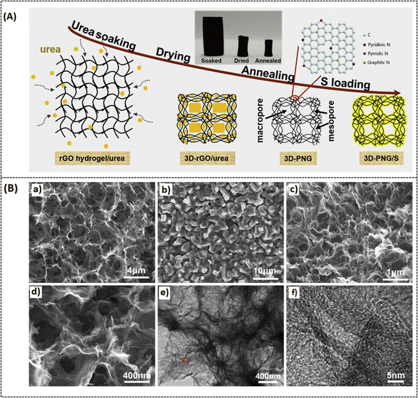 |
| | Fig. 6 (A) Schematic illustration of the preparation process of 3D-PNG/S composites, (B) (a and b) SEM images of 3D-rGO, 3D-rGO@ures, (c and d) low-high-magnification of 3D-PNG (e and f) TEM image of 3D-PNG, HRTEM image of the marked area in. Reprinted with permission,56 Copyright (2019) from Elsevier. | |
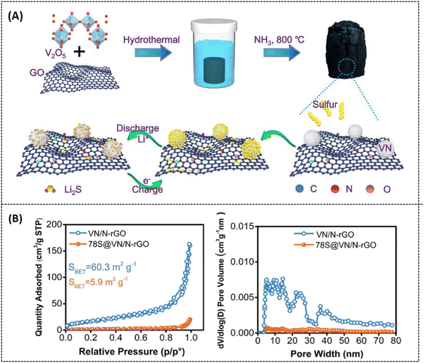 |
| | Fig. 7 (A) Schematic representation of sulfur-doped VN/N-rGO, (B) (a) Nitrogen adsorption/desorption isotherms response and (b) pore size distribution graph of VN/N-rGO and S-VN/N-rGO. Reprinted with permission,61 Copyright (2020) from Elsevier. | |
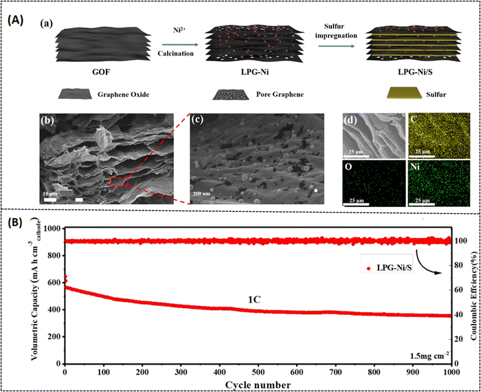 |
| | Fig. 8 (A) (a) Schematic representation of the as-prepared LPG-Ni/S composite, (b–d) cross-sectional FESEM images of LPG-Ni at various magnifications and its corresponding elemental mapping of C, O, Ni. (B) Long-term cycling performance of the LPG-Ni/S cathode material. Reprinted with permission,63 Copyright (2022) from Elsevier. | |
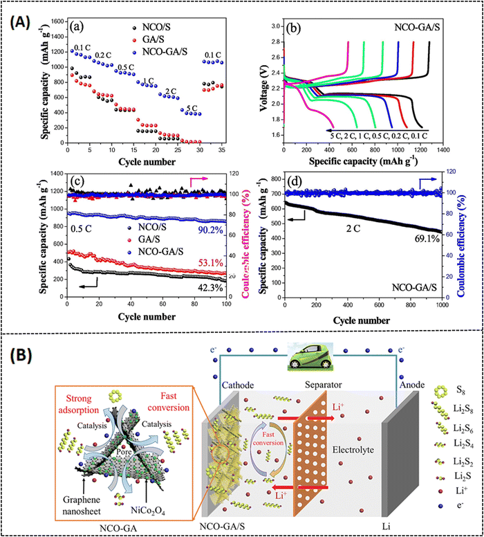 |
| | Fig. 9 (A) (a) Rate performance of NCO/S, GA/S and NCO-GA/S cathodes (b) charge–discharge responses of NCO-GA/S at different charge rates, (c) cycling performances of different electrodes at 0.5C (d) Long-term cycling stability test at 2C and (B). Electrochemical performance of NCO-GA and a model electrode setup of NCO-GA/S composite for lithium–sulfur battery application. Reprinted with permission,64 Copyright (2022) from Elsevier. | |
2.3 Recent progress in porous graphene-based sodium-ion batteries
LIBs have greatly progressed in the past several years and acquired high demand in the industry, but there are some limitations, like an increase in toxicity, demand for lithium sources, and limited lithium extractions.65 Therefore, it is necessary to switch to an alternative rechargeable battery with eco-friendly, low-cost, and high-performance systems. Sodium-ion batteries (SIBs) have been identified as an appealing alternative to LIBs because less expensive, abundant in nature, and less toxic.66 However, the heavier mass and larger radius of Na+ inevitably result in lower electrochemical kinetics and larger volume expansion of active materials than that of lighter and smaller Li+. Interestingly, various cathode materials for SIBs have been derived from previously established LIB cathode materials in order to evaluate the electrochemical performances (LiCoO2 as NaCoO2 and LiFePO4 as NaFePO4) of those electrodes in SIBs.67 However, the large ionic radius of sodium (1.02 Å) may cause a small number of sodium ions to intercalate into graphite, this makes it difficult to make use of graphite anodes in SIB systems.68,69 Hence, other forms of carbon-based materials like graphene and carbon nanotubes have been studied as positive electrode materials for the improved electrochemical performance of SIBs.70,71 Moreover, optimizing the test conditions for graphene-based electrode materials and investigating the sodium storage mechanism for SIBs are some of the challenging research issues.
In the study of nitrogen-doped porous graphene (N-3DPG) for high-performance SIBs by Qiao et al., the mechanism of intercalation and deintercalation of sodium ions on the graphene network surface during the redox reaction process is described in detail.68 Template sources such as polystyrene (PS) nanospheres and melamine are used as starting materials to prepare N-3DPG. Graphene oxide and PS were combined with a varying weight percent ratio of melamine (1, 2, 4, or 8), followed by freeze drying and carbonization (Fig. 10A). The typical surface morphology of the optimal composites is depicted in Fig. 10B. The reported high specific capacitance is about 310 mA h g−1 after 500 cycles at a current density of 0.2 A g−1 and the reversible capability is about 169 mA h g−1 at a high current density of 10 A g−1. Based on the melamine concentration, the highest specific surface area reported in the as-prepared N-3DPG system is around 224 m2 g−1. The random distribution of melamine is the likely reason for a major impediment in the electrochemical performance of the as-prepared system.72
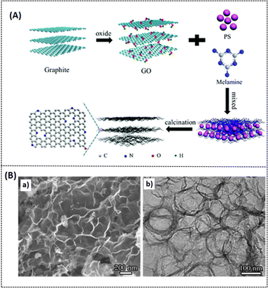 |
| | Fig. 10 (A) Schematic representation of preparation protocol of N-3DPG, (B) (a and b) FE-SEM and TEM images of N-3DPG. Reproduced with permission,72 Copyright (2017), Royal Society of Chemistry. | |
Wang et al. reported on a metal sulfide/graphene-based (FeS2-C/RG) composite for SIB applications using the hydrothermal approach. Among various metal sulfide materials, iron disulfide (FeS2) is a widely available and attractive metal sulfide material, with a theoretical capacitance of 894 mA h g−1.73 Various FeS2/carbon-based composites have previously investigated the capacitance loss due to the volume expansion during the FeS2 to Na2S electrochemical cycling process.74–76 In this study, reported by Wang et al., Prussian blue nanomaterials and rGO were used as a starting precursor for the fabrication of porous FeS2-C/RG-based composites. The reported specific capacitance is 1196 mA h g−1 at 0.1 A g−1 and this capacitance remains at 655.9 mA h g−1 even after 100 cycles at a current density of 0.1 A g−1. The composite also possesses a high specific surface area of about 245.93 m2 g−1 as tabulated in Table 2. It is noteworthy that the inclusion of rGO suppressed the aggregation of FeS2 nanoparticles on the composite surface (Fig. 11)73 and improved the overall capacitance performance. Following this trend, another report was studied by Yue et al. on PVA-based, indium sulfide (In2S3) graphene porous 3D composite (PVA In2S3/rG) prepared as a positive electrode material for enhanced SIB performance (refer to Table 1). The reported surface area for the optimal composite system is around 193.5 m2 g−1. The initial and final capacities of this PVA-inducive In2S3/rG composite are around 565 and 770 mA h g−1 at a current density of 200 mA g−1 and a reversible capacitance value of 509 mA h g−1.77 Zhang et al. reported on amorphous silicon (Si) composite coated with rGO (a-Si/rGO) as a positive material for SIB applications. The composite was prepared by sodiothermic reduction of hollow silica nanoboxes (SiO2 HNB) and then coated with rGO by electrostatic interactions. The optimal a-Si/rGO composite exhibits an initial capacitive discharge of 681.6 mA h g−1 at an applied current density of 100 mA g−1 and capacitive stability (142.1 mA h g−1) for more than 2000 cycles at 800 mA g−1, with a reported specific surface area of around 199 m2 g−1 (refer Table 2).78 Graphene inhibition improved surface and electrical properties, and porous a-Si enhanced the sodium diffusion mechanism at the electrode/electrolyte interface for better battery performance.
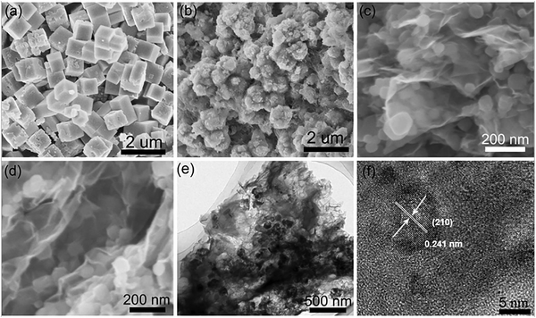 |
| | Fig. 11 SEM morphology of (a) PB, (b) FeS2-C, (c) PB/r-GO, (d) FeS2-C/RG, (e and f) TEM and HRTEM images of optimal FeS2-C/RG. Reprinted with permission,73 Copyright (2020) from Elsevier. | |
2.4 Recent progress in porous graphene-based supercapacitors
Among various energy storage devices, supercapacitors have been extensively studied for the development of portable electronic applications due to their high energy density, rate capability, and safe operation.79 Conventional electric double-layer capacitors (EDCL) store charge electrostatically at the electrode/electrolyte interface (non-faradaic process).80 Among various capacitance measurements, pseudo-capacitive materials have emerged with completely different electrochemical energy storage mechanisms (such as batteries) in which the current response is neither purely capacitive nor faradaic.81 It is well known that supercapacitors have limited energy storage but high-power density, while batteries have low power density but high energy density. A device with the combined characteristics of both systems (battery and supercapacitor) is expected to achieve high power density and high energy density simultaneously. In this context, there is growing research interest in asymmetric and hybrid supercapacitors,82,83 which improve not only the electrochemical performance but also the cycle stability and lifetime of supercapacitors.84,85 Various metal oxides/hydroxides and conducting polymers doped with carbonaceous materials are utilized as positive and negative electrodes, and these electrodes are usually described in the research report.86–89 However, these electrodes experienced low conductivity and large volume changes during the cycling process, resulting in low power density and flat stability.90 A complication observed in carbonaceous electrode materials for supercapacitors is the low energy density due to the lamination of carbon, which limits the surface exposure to the charge storage mechanism, and results in low capacitance activity.91 To overcome this problem, research is being carried out to increase the surface area by utilizing porous graphene-based electrode materials for enhanced capacitance performance. For instance, Sethi et al. have reported on porous graphene-based NiCo2O4 nanorod doped hybrid composites (PGNCs) for supercapacitor applications.92 The porous structural hybrid composite was created using a solvothermal method with a varying weight % of GO in the NiCo2O4 system, followed by heating at 400 °C. The highest capacitance measured with the optimal composite (10PGNC) is 1684 F g−1 with 1 A g−1 applied current under 2 M KOH electrolyte condition (Fig. 12b). As shown in Fig. 12d, the cycling stability of the as-prepared composite could hold 94% of the initial capacitance value for 10![[thin space (1/6-em)]](https://www.rsc.org/images/entities/char_2009.gif) 000 cycles at a current density of 8 A g−1. The optimal electrode as a working system achieved the high energy and high-power density of 45.3 W h kg−1 and 17843.5 W kg−1 (as tabulated in Table 3), respectively. Such an improvement in electrochemical behavior can be attributed to the synergic interaction of GO and NiCo2O4 in the composite system. Recently, Cheng et al.93 reported a nitrogen-doped ionic liquid-based porous graphene aerogel (UPGA) composite prepared by a hydrothermal approach for supercapacitor applications. They utilized urea phosphate as a source material for nitrogen doping, and phosphate also acts as a protective barrier to retain the hydroxyl group present on the surface of graphene oxide. This prevention of oxygen-rich functional groups (functionalization) is very important to tune the bandgap and other physicochemical properties of graphene to improve its electrical performance.94 The surface morphology of the optimal samples is shown in Fig. 13A. The reported specific capacitance of the optimal sample is 196.7 F g−1 at a current density of 1 A g−1 (refer to Table 3). The energy density of the symmetric electrode material is around 97.2 W h kg−1 at a power density of 0.9 kW kg−1 and demonstrated good capacitance retention of 78% after 5500 cycles at 1 A g−1 (Fig. 13B). Similarly, Gao et al. reported on nitrogen-doped porous graphene composites (GO/PANI nanorods array/GO electrode = GPGC) prepared by combining polyaniline nanorod arrays and graphene oxide, then chemically activating the samples with KOH at 700 °C in an N2 atmosphere.95 The as-prepared porous GPGC composite was reported to have a high specific surface area of 2837 m2 g−1 as a result of the inclusion of porous graphene oxide (Fig. 14). The specific capacitance was around 507 F g−1 at 1 A g−1 for the as-prepared porous composite in three-electrode measuring technique, and the cycling stability was around 96.8% at an applied current density of 10 A g−1 after 1000 cycles (refer Table 3). The same composite was also studied for symmetric capacitance (two-electrode energy storage system as in Table 1) and the reported specific capacitance was 28.3 W h kg−1 at the specific power of 700 W kg−1 respectively. The inclusion of GO enhanced the surface morphology as well as the electrochemical performance of the GPGC composite. Similarly, Tao et al. reported on 3D porous graphene-like electrode material with naturally doped nitrogen content (3D BPGC) by utilizing activated biocarbon from mantis shrimp shell for supercapacitor applications. The specific surface area of the as-prepared 3D BPGC nanomaterial is about 2300 m2 g−1. The symmetric capacitance offered by the porous electrode material is 317.2 F g−1 at 0.5 A g−1 at 2 M MgSO4 + 0.05 M FeSO4 electrolyte condition (refer to Fig. 15A and Table 1). The composite could maintain 87.2% of the initial capacitance value over 30
000 cycles at a current density of 8 A g−1. The optimal electrode as a working system achieved the high energy and high-power density of 45.3 W h kg−1 and 17843.5 W kg−1 (as tabulated in Table 3), respectively. Such an improvement in electrochemical behavior can be attributed to the synergic interaction of GO and NiCo2O4 in the composite system. Recently, Cheng et al.93 reported a nitrogen-doped ionic liquid-based porous graphene aerogel (UPGA) composite prepared by a hydrothermal approach for supercapacitor applications. They utilized urea phosphate as a source material for nitrogen doping, and phosphate also acts as a protective barrier to retain the hydroxyl group present on the surface of graphene oxide. This prevention of oxygen-rich functional groups (functionalization) is very important to tune the bandgap and other physicochemical properties of graphene to improve its electrical performance.94 The surface morphology of the optimal samples is shown in Fig. 13A. The reported specific capacitance of the optimal sample is 196.7 F g−1 at a current density of 1 A g−1 (refer to Table 3). The energy density of the symmetric electrode material is around 97.2 W h kg−1 at a power density of 0.9 kW kg−1 and demonstrated good capacitance retention of 78% after 5500 cycles at 1 A g−1 (Fig. 13B). Similarly, Gao et al. reported on nitrogen-doped porous graphene composites (GO/PANI nanorods array/GO electrode = GPGC) prepared by combining polyaniline nanorod arrays and graphene oxide, then chemically activating the samples with KOH at 700 °C in an N2 atmosphere.95 The as-prepared porous GPGC composite was reported to have a high specific surface area of 2837 m2 g−1 as a result of the inclusion of porous graphene oxide (Fig. 14). The specific capacitance was around 507 F g−1 at 1 A g−1 for the as-prepared porous composite in three-electrode measuring technique, and the cycling stability was around 96.8% at an applied current density of 10 A g−1 after 1000 cycles (refer Table 3). The same composite was also studied for symmetric capacitance (two-electrode energy storage system as in Table 1) and the reported specific capacitance was 28.3 W h kg−1 at the specific power of 700 W kg−1 respectively. The inclusion of GO enhanced the surface morphology as well as the electrochemical performance of the GPGC composite. Similarly, Tao et al. reported on 3D porous graphene-like electrode material with naturally doped nitrogen content (3D BPGC) by utilizing activated biocarbon from mantis shrimp shell for supercapacitor applications. The specific surface area of the as-prepared 3D BPGC nanomaterial is about 2300 m2 g−1. The symmetric capacitance offered by the porous electrode material is 317.2 F g−1 at 0.5 A g−1 at 2 M MgSO4 + 0.05 M FeSO4 electrolyte condition (refer to Fig. 15A and Table 1). The composite could maintain 87.2% of the initial capacitance value over 30![[thin space (1/6-em)]](https://www.rsc.org/images/entities/char_2009.gif) 000 cycles at 1 A g−1 and the gravimetric energy density is around 17.7 W h kg−1 at a power density of 180 W kg−1, respectively. This proposed porous material delivered improved cycling stability due to the optimized porous structure (Fig. 15B)96 and the surface property of activated carbon material. Morenghi et al. reported an asymmetric supercapacitor (ASC) using a nickel-doped nanoparticle incorporated porous graphene hybrid (Ni-TEGO) composite system. The graphene was synthesized by thermal exfoliation of graphite oxide (TEGO) at 1150 °C under high vacuum conditions and this graphene oxide possessed a specific surface area of 500 m2 g−1 and electrical conductivity of 9.5 S cm−1, respectively. When the individual electrodes (Ni-TEGO and TEGO) were subjected to a three-electrode system, the reported specific capacitance was 1900 and 310 F g−1 at a scan rate of 2 mV s−1 as shown in Fig. 16A. However, the developed ASC with Ni-TEGO as positive and TEGO as negative electrodes in 3.5 M KOH electrolyte medium showed impressive specific energy of 37 W h kg−1 at 40 mA g−1 and 10 W h kg−1 at 10 A g−1 of applied current density, respectively. The assembled ASC electrodes possessed excellent capacitance retention of 72% over 10
000 cycles at 1 A g−1 and the gravimetric energy density is around 17.7 W h kg−1 at a power density of 180 W kg−1, respectively. This proposed porous material delivered improved cycling stability due to the optimized porous structure (Fig. 15B)96 and the surface property of activated carbon material. Morenghi et al. reported an asymmetric supercapacitor (ASC) using a nickel-doped nanoparticle incorporated porous graphene hybrid (Ni-TEGO) composite system. The graphene was synthesized by thermal exfoliation of graphite oxide (TEGO) at 1150 °C under high vacuum conditions and this graphene oxide possessed a specific surface area of 500 m2 g−1 and electrical conductivity of 9.5 S cm−1, respectively. When the individual electrodes (Ni-TEGO and TEGO) were subjected to a three-electrode system, the reported specific capacitance was 1900 and 310 F g−1 at a scan rate of 2 mV s−1 as shown in Fig. 16A. However, the developed ASC with Ni-TEGO as positive and TEGO as negative electrodes in 3.5 M KOH electrolyte medium showed impressive specific energy of 37 W h kg−1 at 40 mA g−1 and 10 W h kg−1 at 10 A g−1 of applied current density, respectively. The assembled ASC electrodes possessed excellent capacitance retention of 72% over 10![[thin space (1/6-em)]](https://www.rsc.org/images/entities/char_2009.gif) 000 cycles as shown in Fig. 16B.97 Such high capacitance is due to the synergic interaction of graphene with nickel nanoparticle composition coated onto the nickel foam disk. Similarly, Zhou et al. studied the symmetric capacitance of porous graphene/composite using activated silk cocoon fibroins/exfoliated graphene (represented as KCC) as a starting material.98 The as-prepared silk-derived carbon material was pyrolyzed and then chemically activated with KOH at different temperatures. The reported specific surface area of the optimal composite material was 1281.8 m2 g−1 and exhibited a specific capacitance of 290 F g−1 at an applied current density of 0.2 A g−1 (refer to Table 3). The maximum energy density is about 12.9 W h kg−1 at 95 W kg−1 power density. Overall, the composite possesses 86% of capacitance retention at 0.75 A g−1 after 10
000 cycles as shown in Fig. 16B.97 Such high capacitance is due to the synergic interaction of graphene with nickel nanoparticle composition coated onto the nickel foam disk. Similarly, Zhou et al. studied the symmetric capacitance of porous graphene/composite using activated silk cocoon fibroins/exfoliated graphene (represented as KCC) as a starting material.98 The as-prepared silk-derived carbon material was pyrolyzed and then chemically activated with KOH at different temperatures. The reported specific surface area of the optimal composite material was 1281.8 m2 g−1 and exhibited a specific capacitance of 290 F g−1 at an applied current density of 0.2 A g−1 (refer to Table 3). The maximum energy density is about 12.9 W h kg−1 at 95 W kg−1 power density. Overall, the composite possesses 86% of capacitance retention at 0.75 A g−1 after 10![[thin space (1/6-em)]](https://www.rsc.org/images/entities/char_2009.gif) 000 cycles. The high cycling stability of the reported composite is due to N and O heteroatoms present in the carbonized samples.
000 cycles. The high cycling stability of the reported composite is due to N and O heteroatoms present in the carbonized samples.
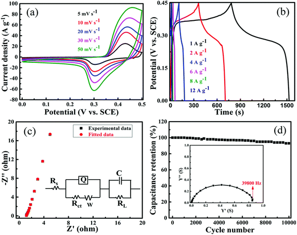 |
| | Fig. 12 Electrochemical responses of 10 PGNC composite (a–d) CV curves at different scan rates, GCD at different applied current densities, Impedance plot, cycling stability at 8 A g−1 with admittance plot. Reproduced with permission,92 Copyright (2020), Royal Society of Chemistry. | |
Table 3 Tabulation on synthesis, surface area and electrochemical performance of porous graphene-based materials for supercapacitors discussed in this manuscript
| S.no |
Porous graphene based electrode material |
Synthesis method |
SSA (m2 g−1) |
Capacitance & current density |
Type of capacitor (energy & power density) |
Cycling performance in (%) |
Ref. |
| 1. |
PGNC composite |
Hydrothermal synthesis using GO/NiCo2O4/Urea followed by calcination |
109 |
1684 F g−1 at 1 A g−1 |
Symmetric (45.3 W h kg−1 at 1784.5 W kg−1) |
94% at 8 A g−1 after 10![[thin space (1/6-em)]](https://www.rsc.org/images/entities/char_2009.gif) 000 cycles 000 cycles |
92
|
| 2. |
N-graphene aerogel (UPGA) |
Hydrothermal synthesis using urea phosphate |
— |
196.7 F g−1 at 1 A g−1 |
Symmetric (97.2 W h kg−1 at 0.9 kW kg−1) |
78.3% at 1 A g−1 after 5500 cycles |
93
|
| 3. |
GO/PANI nanorods |
Chemical activation of PANI/GO by KOH |
2837 |
507 F g−1 at 1 A g−1 |
Symmetric (28.3 W h kg−1 at 700 W kg−1) |
96.8% at 10 A g−1 after 1000 cycles |
95
|
| 4. |
3D BPGC |
Carbonization of mantis shrimp shell and KOH activation |
2300 |
317 F g−1 at 0.5 A g−1 |
Symmetric (17.7 W h kg−1 at 180 W kg−1) |
87.2% at 1 A g−1 over 30![[thin space (1/6-em)]](https://www.rsc.org/images/entities/char_2009.gif) 000 cycles 000 cycles |
96
|
| 5. |
Ni-TEGO |
Thermal exfoliation of graphite oxide at 1150 °C |
500 |
1900 F g−1 at 2 mV s−1 |
Asymmetric (37 W h kg−1 at 40 mA g−1) |
72% at 1 A g−1 over 10![[thin space (1/6-em)]](https://www.rsc.org/images/entities/char_2009.gif) 000 cycles 000 cycles |
97
|
| 6. |
Porous graphene |
Carbonization followed by chemical activation of silk cocoon fibroins and exfoliated graphene sheet |
1281.8 |
290 F g−1 at 0.2 A g−1 |
Symmetric (12.9 W h kg−1 at 95 W kg−1) |
86% at 0.5 A g−1 over 10![[thin space (1/6-em)]](https://www.rsc.org/images/entities/char_2009.gif) 000 cycles 000 cycles |
98
|
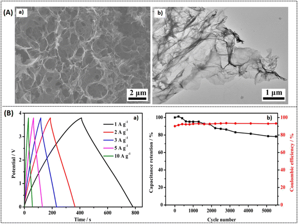 |
| | Fig. 13 (A) SEM images of (a) UPGA and (b) TEM image of UPGA, (B) electrochemical Response of UPGA: (a) GCD response (b) cycling stability vs. coulombic efficiency at 1 A g−1. Reprinted with permission,93 Copyright (2021) from Elsevier. | |
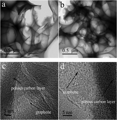 |
| | Fig. 14 TEM images of (a and c) nitrogen doped porous carbon (b and d), porous GO/PANI nanorods array/GO electrode (GPGC) composite. Reprinted with permission,95 Copyright (2021) from Elsevier. | |
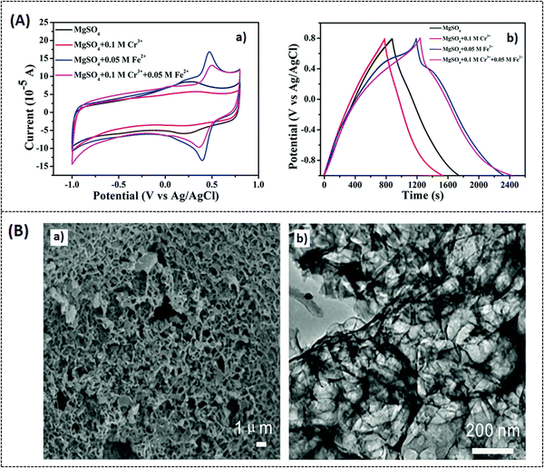 |
| | Fig. 15 (A) (a and b) CV response of optimal composite BPGC at different electrolyte medium at a scan rate 5 mV s−1, GCD response at 0.5 A g−1 current density. (B) (a and b) SEM and TEM images of BPGC. Reproduced with permission,96 Copyright (2022), Royal Society of Chemistry. | |
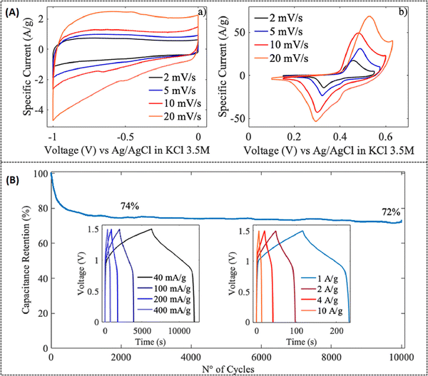 |
| | Fig. 16 (A) (a and b) CV response of TEGO and Ni-TEGO at different scan rates, (B) capacitance retention response of ASCs over 10![[thin space (1/6-em)]](https://www.rsc.org/images/entities/char_2009.gif) 000 cycles at 1 A g−1 current density inset: with GCD curves at different applied current density. Reprinted with permission,97 Copyright (2022) from Elsevier. 000 cycles at 1 A g−1 current density inset: with GCD curves at different applied current density. Reprinted with permission,97 Copyright (2022) from Elsevier. | |
3. Role of intrinsic defects on carbonaceous materials
In the field of energy storage and conversion systems, the beneficial functions of defective (both intrinsic and extrinsic) carbonaceous materials have been extensively studied to improve the performance of rechargeable batteries and electrocatalysts.99,100 Defect engineering is considered as an effective means of modifying the surface chemistry of carbon skeleton and thus promoting electrochemical reactivity. In carbonaceous materials, intrinsic defects (in 3D structures) are divided into three categories: topological defects, carbon vacancy defects, and edge defects. Whereas, extrinsic defects are caused by the intercalation of dopants in the crystal lattice and it includes doping of heteroatoms (N, S, B, etc.) and metal atoms (Fe, Co, Ni, etc.).101 In particular, carbon vacancies (intrinsic defect) refer to the absence of one or a few carbon atoms, and hole defects refer to the absence of a large number of carbon atoms, causing a hierarchical porous structure with the formation of micropores, mesopores, and macropores on the surface network.101 This type of defect engineering may modify the surface-to-porous ratio in the graphene network and serve as an effective active center to facilitate more synergetic active sites. These synergetic active sites promote more charge transfer at the surface of porous graphene, facilitating improved electrochemical performance.102,103 According to Wang et al.,104 these intrinsic defect structural carbons have the capacity to improve the π–π electron donor–acceptor interactions. Many current reports claim that intrinsic defects have better electrochemical activity than those doped with heteroatoms, and this interesting fact has generated much research interest in defective carbonaceous materials (such as porous graphene) for a variety of energy-related applications and their industrialization.105–107
4. Summary and future perspective
Porous graphene-based electrode materials are promising candidates for the fabrication of electrochemical energy storage devices. Other energy devices utilizing conventional graphene systems greatly suffer from the aggregation/re-stacking of graphene sheets, resulting in poor energy storage performance hindering their practical applications. Interestingly, 3D porous graphene allows the electrolyte (containing ions) to reach the graphene surface layer more quickly and this characteristic feature promotes improved capacitance activity, fast charge transfer, and long-term stability.
Recently, there has been an increasing research interest in porous graphene electrodes with more edge, basal plane structures for energy and other applications. The most recent developments in 3D porous graphene-based electrodes are discussed in this review with regards to achieving optimal electrochemical charge-storage performances in batteries. Porous graphene nanomaterials, however, still have some challenges to be resolved: firstly, the precise controlling of homogeneity in the pore size, structure, and pore morphology by the synthesis conditions still remains a challenge in optimizing the structural properties of porous systems. In general, the preconditioning of starting materials, doping agents (heteroatoms and metal species) used, and preparation methods all together contribute to the porous surface designing. In addition to this, the process of preparing porous graphene involves multiple steps using different raw materials, which sometimes results in a low yield of carbon. Secondly, choosing cost-effective starting materials with longevity and stability for large-scale industrialization of porous graphene-based energy storage systems still remains a challenging task. Third, many research papers also lack information on energy storage per unit volume (volumetric energy density), which is an important parameter for commercializing porous graphene-based materials in energy systems. Numerous studies in the last few years have suggested that 3D porous materials, such as graphene hydrogels and graphene foams, can increase long-term electrochemical cycling stability by preventing the stacking of graphene sheets, so this finding should prompt researchers to focus more on developing edge-plane site porous surface materials. In the future, crystalline porous organic frameworks like organic cages, covalent triazine frameworks (CTFs), porous aromatic frameworks (PAFs), covalent organic frameworks (COFs), hyper-crosslinked polymers (HCPs), and conjugated microporous polymers (CMP) may be used as source materials for the preparation of porous graphene. By this way of synthesis, it is possible to realize highly periodic porous structures that are advantageous for energy storage performance.
It is true that porous graphene is a novel system, and if the above-mentioned problems can be effectively solved or rectified, 3D porous graphene has the potential to serve as an innovative nanomaterial for the manufacture of advanced energy storage devices in the future.
Conflicts of interest
The authors declare no conflict of interest.
Acknowledgements
The authors would like to thank the “ENSEMBLE3-Centre of Excellence for nanophononics, advanced materials, and novel crystal growth-based technologies” project (GA no. MAB/2020/14) carried out within the international research agendas program of the foundation for Polish science co-financed by the European Union under the European regional development fund and the European Union's Horizon 2020 (H2020 European Commission-Research Executive Agency) research and innovation program teaming for excellence (GA. no. 857543) for supporting this work. The authors would like to appreciate Ms Harshilp Dixit, a mechanical engineering student from Vellore Institute of Technology for creative designing of the journal cover page.
References
- J. F. Mercure, H. Pollitt, J. E. Viñuales, N. R. Edwards, P. B. Holden, U. Chewpreecha, P. Salas, I. Sognnaes, A. Lam and F. Knobloch, Nat. Clim. Change, 2018, 8(7), 588–593 CrossRef.
- C. Wang, R. Yu, W. Luo, W. Feng, Y. Shen, N. Xu and L. Mai, Nano Res., 2022, 15(10), 9019–9025 CrossRef CAS.
- C. Zhao, Y. Liu, S. Beirne, J. Razal and J. Chen, Adv. Mater. Technol., 2018, 3(9), 1800028 CrossRef.
- Y. M. Chiang, Science, 2010, 330(6010), 1485–1486 CrossRef CAS PubMed.
- P. Simon and Y. Gogotsi, Nat. Mater., 2008, 7(11), 845–854 CrossRef CAS PubMed.
- V. Simone, L. Lecarme, L. Simonin and S. Martinet, J. Electrochem. Soc., 2016, 164(2), A145 CrossRef.
- A. Barré, B. Deguilhem, S. Grolleau, M. Gérard, F. Suard and D. Riu, J. Power Sources, 2013, 241, 680–689 CrossRef.
- M. Ibrahim, M. G. Fayed, S. G. Mohamed, Z. Wen, X. Sun and H. N. Abdelhamid, ACS Appl. Energy Mater., 2022, 5(10), 12828–12836 CrossRef CAS.
- Q. Wang, H. Wang, L. Wang, L. Bai, C. Yang and T. Zhu, Microchem. J., 2021, 170, 106710 CrossRef CAS.
- K. S. Novoselov, A. K. Geim, S. V. Morozov, D. E. Jiang, Y. Zhang, S. V. Dubonos, I. V. Grigorieva and A. A. Firsov, Science, 2004, 306(5696), 666–669 CrossRef CAS PubMed.
- S. Q. Li, L. Zhang, T. T. Liu, Y. W. Zhang, C. Guo, Y. Wang and F. H. Du, Adv. Mater., 2022, 34(24), 2201801 CrossRef CAS PubMed.
- G. Huang, J. Han, F. Zhang, Z. Wang, H. Kashani, K. Watanabe and M. Chen, Adv. Mater., 2019, 31(2), 1805334 CrossRef PubMed.
- K. I. Bolotin, K. J. Sikes, Z. Jiang, M. Klima, G. Fudenberg, J. Hone, P. Kim and H. L. Stormer, Solid State Commun., 2008, 146(9–10), 351–355 CrossRef CAS.
- A. K. Geim and K. S. Novoselov, Sci. World J., 2010, 11–19 Search PubMed.
- M. J. Allen, V. C. Tung and R. B. Kaner, Chem. Rev., 2010, 110(1), 132–145 CrossRef CAS PubMed.
- Y. Tao, Z. Y. Sui and B. H. Han, J. Mater. Chem. A, 2020, 8(13), 6125–6143 RSC.
- Q. Tang, Z. Zhou and Z. Chen, Nanoscale, 2013, 5(11), 4541–4583 RSC.
- Y. Wang, F. Yuan, Z. Li, D. Zhang, Q. Yu and B. Wang, APL Mater., 2022, 10(3), 030902 CrossRef CAS.
- H. L. Poh, F. Sanek, Z. Sofer and M. Pumera, Nanoscale, 2012, 4(22), 7006–7011 RSC.
- M. Sethi, H. Bantawal, U. S. Shenoy and D. K. Bhat, J. Alloys Compd., 2019, 799, 256–266 CrossRef CAS.
- J. Kim, J. H. Eum, J. Kang, O. Kwon, H. Kim and D. W. Kim, Sci. Rep., 2021, 11(1), 2063 CrossRef CAS PubMed.
- C. Tang, H. F. Wang, J. Q. Huang, W. Qian, F. Wei, S. Z. Qiao and Q. Zhang, Electrochem. Energy Rev., 2019, 2, 332–371 CrossRef CAS.
- X. Huang, Y. Zhao, Z. Ao and G. Wang, Sci. Rep., 2014, 4(1), 7557 CrossRef CAS PubMed.
- L. Zhang, J. Yue, T. Wei, Z. Liu, J. Zhou, C. Liu, H. Jiang, Z. Jiang and Z. Fan, Carbon, 2019, 142, 327–336 CrossRef CAS.
- W. Chen, M. Wan, Q. Liu, X. Xiong, F. Yu and Y. Huang, Small Methods, 2019, 3(4), 1800323 CrossRef CAS.
- S. Vadukumpully, J. Paul, N. Mahanta and S. Valiyaveettil, Carbon, 2011, 49(1), 198–205 CrossRef CAS.
- G. Brunetto, P. A. S. Autreto, L. D. Machado, B. I. Santos, R. P. Dos Santos and D. S. Galvao, J. Phys. Chem. C, 2012, 116(23), 12810–12813 CrossRef CAS.
- H. K. Kim, S. M. Bak, S. W. Lee, M. S. Kim, B. Park, S. C. Lee, Y. J. Choi, S. C. Jun, J. T. Han, K. W. Nam and K. Y. Chung, Energy Environ. Sci., 2016, 9(4), 1270–1281 RSC.
- G. Fu, X. Yan, Y. Chen, L. Xu, D. Sun, J. M. Lee and Y. Tang, Adv. Mater., 2018, 30(5), 1704609 CrossRef PubMed.
- K. Lu, H. Zhang, B. Song, W. Pan, H. Ma and J. Zhang, Electrochim. Acta, 2019, 296, 755–761 CrossRef CAS.
- C. Yang, N. Hu, W. Wang and B. Cao, J. Power Sources, 2018, 399, 115–124 CrossRef CAS.
- J. Li, W. Qin, J. Xie, H. Lei, Y. Zhu, W. Huang, X. Xu, Z. Zhao and W. Mai, Nano Energy, 2018, 53, 415–424 CrossRef CAS.
- W. Yuan, Y. Zhou, Y. Li, C. Li, H. Peng, J. Zhang, Z. Liu, L. Dai and G. Shi, Sci. Rep., 2013, 3, 2248 CrossRef PubMed.
- M. Armand and J. M. Tarascon, Nature, 2008, 451(7179), 652–657 CrossRef CAS PubMed.
- Y. Wu, Y. Wei, J. Wang, K. Jiang and S. Fan, Nano Lett., 2013, 13(2), 818–823 CrossRef CAS PubMed.
- H. Kim and J. Cho, Nano Lett., 2008, 8(11), 3688–3691 CrossRef CAS PubMed.
- A. L. M. Reddy, A. Srivastava, S. R. Gowda, H. Gullapalli, M. Dubey and P. M. Ajayan, ACS Nano, 2010, 4(11), 6337–6342 CrossRef CAS PubMed.
- J. Xiao, D. Mei, X. Li, W. Xu, D. Wang, G. L. Graff, W. D. Bennett, Z. Nie, L. V. Saraf, I. A. Aksay and J. Liu, Nano Lett., 2011, 11(11), 5071–5078 CrossRef CAS PubMed.
- X. Zhu, J. Ye, Y. Lu and X. Jia, ACS Sustainable Chem. Eng., 2019, 7(13), 11241–11249 CrossRef CAS.
- Q. Xie, S. Qu, Y. Zhang and P. Zhao, Appl. Surf. Sci., 2021, 537, 148092 CrossRef CAS.
- Q. Feng, T. Li, Y. Sui, B. Xiao, T. Wang, Z. Sun, J. Qi, F. Wei, Q. Meng, Y. Ren and X. Xue, J. Alloys Compd., 2021, 884, 160923 CrossRef CAS.
- Y. Mo, S. Li and J. Yu, ACS Appl. Nano Mater., 2022, 5(6), 8205–8213 CrossRef CAS.
- C. H. Yim, S. Niketic, N. Salem, O. Naboka and Y. Abu-Lebdeh, J. Electrochem. Soc., 2016, 164(1), A6294 CrossRef.
- G. Zhou, S. Pei, L. Li, D. W. Wang, S. Wang, K. Huang, L. C. Yin, F. Li and H. M. Cheng, J. Adv. Mater., 2014, 26(4), 664 CrossRef.
- T. Li, X. Bai, U. Gulzar, Y. J. Bai, C. Capiglia, W. Deng, X. Zhou, Z. Liu, Z. Feng and R. Proietti Zaccaria, Adv. Funct. Mater., 2019, 29(32), 1901730 CrossRef.
- A. Manthiram, Y. Fu, S. H. Chung, C. Zu and Y. S. Su, Chem. Rev., 2014, 114(23), 11751–11787 CrossRef CAS PubMed.
- Z. Li, C. Li, X. Ge, J. Ma, Z. Zhang, Q. Li, C. Wang and L. Yin, Nano Energy, 2016, 23, 15–26 CrossRef CAS.
- D. Li, F. Han, S. Wang, F. Cheng, Q. Sun and W. C. Li, ACS Appl. Mater. Interfaces, 2013, 5(6), 2208–2213 CrossRef CAS PubMed.
- Y. Q. Lu, Y. J. Wu, T. Sheng, X. X. Peng, Z. G. Gao, S. J. Zhang, L. Deng, R. Nie, J. Swiatowska, J. T. Li and Y. Zhou, ACS Appl. Mater. Interfaces, 2018, 10(16), 13499–13508 CrossRef CAS PubMed.
- J. Choi, T. G. Jeong, B. W. Cho, Y. Jung, S. H. Oh and Y. T. Kim, J. Phys. Chem., 2018, 122(14), 7664–7669 CAS.
- X. J. Hong, C. L. Song, Y. Yang, H. C. Tan, G. H. Li, Y. P. Cai and H. Wang, ACS Nano, 2019, 13(2), 1923–1931 CAS.
- H. T. Le, D. T. Ngo, V. C. Ho, G. Cao, C. N. Park and C. J. Park, J. Mater. Chem. A, 2016, 4(28), 11124–11138 RSC.
- M. Zheng, Y. Chi, Q. Hu, H. Tang, X. Jiang, L. Zhang, S. Zhang, H. Pang and Q. Xu, J. Mater. Chem. A, 2019, 7(29), 17204–17241 RSC.
- D. Cheng, Y. Zhao, X. Tang, T. An, X. Wang, H. Zhou, D. Zhang and T. Fan, Carbon, 2019, 149, 750–759 CrossRef CAS.
- X. Ma, G. Ning, C. Qi, C. Xu and J. Gao, ACS Appl. Mater. Interfaces, 2014, 6(16), 14415–14422 CrossRef CAS PubMed.
- D. Cheng, P. Wu, J. Wang, X. Tang, T. An, H. Zhou, D. Zhang and T. Fan, Carbon, 2019, 143, 869–877 CrossRef CAS.
- Z. W. Seh, J. H. Yu, W. Li, P. C. Hsu, H. Wang, Y. Sun, H. Yao, Q. Zhang and Y. Cui, Nat. Commun., 2014, 5(1), 1–8 CrossRef.
- Z. Yuan, H. J. Peng, T. Z. Hou, J. Q. Huang, C. M. Chen, D. W. Wang, X. B. Cheng, F. Wei and Q. Zhang, Nano Lett., 2016, 16(1), 519–527 CrossRef CAS PubMed.
- R. Mori, Cathode materials for lithium-sulfur battery: a review, J. Solid State Electrochem., 2023, 1–27 Search PubMed.
- R. Wang, J. Lang, P. Zhang, Z. Lin and X. Yan, Adv. Funct. Mater., 2015, 25(15), 2270–2278 CrossRef CAS.
- N. Li, Z. Xu, P. Wang, Z. Zhang, B. Hong, J. Li and Y. Lai, J. Chem. Eng., 2020, 398, 125432 CrossRef CAS.
- T. Zhai, H. Liu, H. Li, X. Fang, M. Liao, L. Li, H. Zhou, Y. Koide, Y. Bando and D. Golberg, J. Adv. Mater., 2010, 22(23), 2547–2552 CrossRef CAS PubMed.
- Y. Zhang, Y. Liu, Z. Zhao, Y. Guo, Q. Li, P. Liu, B. Hu, L. Wang and H. Lu, Appl. Surf. Sci., 2022, 586, 152805 CrossRef CAS.
- X. Tian, Y. Zhou, B. Zhang, N. B. S. Selabi and G. Wang, J. Energy Chem., 2022, 74, 239–251 CrossRef CAS.
- M. Li, J. Lu, Z. Chen and K. Amine, Adv. Mater., 2018, 30(33), 1800561 CrossRef PubMed.
- D. Kundu, E. Talaie, V. Duffort and L. F. Nazar, Angew. Chem., Int. Ed., 2015, 54(11), 3431–3448 CrossRef CAS PubMed.
- P. K. Nayak, L. Yang, W. Brehm and P. Adelhelm, Angew. Chem., Int. Ed., 2018, 57(1), 102–120 CrossRef CAS PubMed.
- Y. Qiao, X. Cheng, Y. Liu, R. Han, M. Ma, Q. Li, H. Dong, X. Li and S. Yang, Inorg. Chem. Front., 2017, 4(12), 2017–2023 RSC.
- Y. U. Park, D. H. Seo, H. S. Kwon, B. Kim, J. Kim, H. Kim, I. Kim, H. I. Yoo and K. Kang, J. Am. Chem. Soc., 2013, 135(37), 13870–13878 CrossRef CAS PubMed.
- X. Yan, H. Ye, X. L. Wu, Y. P. Zheng, F. Wan, M. Liu, X. H. Zhang, J. P. Zhang and Y. G. Guo, J. Mater. Chem. A, 2017, 5(32), 16622–16629 RSC.
- Y. X. Wang, S. L. Chou, H. K. Liu and S. X. Dou, Carbon, 2013, 57, 202–208 CrossRef CAS.
- J. Niu, R. Shao, M. Liu, Y. Zan, M. Dou, J. Liu, Z. Zhang, Y. Huang and F. Wang, Adv. Funct. Mater., 2019, 29(46), 1905095 CrossRef CAS.
- F. Wang, W. Zhang, H. Zhou, H. Chen, Z. Huang, Z. Yan, R. Jiang, C. Wang, Z. Tan and Y. Kuang, J. Chem. Eng., 2020, 380, 122549 CrossRef CAS.
- A. Douglas, R. Carter, L. Oakes, K. Share, A. P. Cohn and C. L. Pint, ACS Nano, 2015, 9(11), 11156–11165 CrossRef CAS PubMed.
- Y. Chen, X. Hu, B. Evanko, X. Sun, X. Li, T. Hou, S. Cai, C. Zheng, W. Hu and G. D. Stucky, Nano Energy, 2018, 46, 117–127 CrossRef CAS.
- Z. Hu, Z. Zhu, F. Cheng, K. Zhang, J. Wang, C. Chen and J. Chen, Energy Environ. Sci., 2015, 8(4), 1309–1316 RSC.
- L. Yue, Z. Yu, X. Cheng, C. Feng, W. Xu, X. Si, F. Zhang, G. Hou, R. Guan and W. Zhang, Electrochim. Acta, 2021, 370, 137722 CrossRef CAS.
- Y. Zhang, Y. C. Tang, X. T. Li, H. Liu, Y. Wang, Y. Xu and F. H. Du, ACS Omega, 2022, 7(34), 30208–30214 CrossRef CAS PubMed.
- Y. Zheng, Y. Yang, S. Chen and Q. Yuan, CrystEngComm, 2016, 18(23), 4218–4235 RSC.
- Q. Zhu, D. Zhao, M. Cheng, J. Zhou, K. A. Owusu, L. Mai and Y. Yu, Adv. Energy Mater., 2019, 9(36), 1901081 CrossRef.
- J. Come, V. Augustyn, J. W. Kim, P. Rozier, P. L. Taberna, P. Gogotsi, J. W. Long, B. Dunn and P. Simon, J. Electrochem. Soc., 2014, 161(5), A718 CrossRef CAS.
- T. Brousse, D. Belanger and J. W. Long, J. Electrochem. Soc., 2015, 162(5), A5185 CrossRef CAS.
- K. Sun, F. Hua, S. Cui, Y. Zhu, H. Peng and G. Ma, RSC Adv., 2021, 11(59), 37631–37642 RSC.
- X. Cheng, J. Zhang, J. Ren, N. Liu, P. Chen, Y. Zhang, J. Deng, Y. Wang and H. Peng, J. Phys. Chem. C, 2016, 120(18), 9685–9691 CrossRef CAS.
- N. R. Chodankar, D. P. Dubal, S. H. Ji and D. H. Kim, Small, 2019, 5(19), 1901145 CrossRef PubMed.
- G. A. Snook, P. Kao and A. S. Best, J. Power Sources, 2011, 196(1), 1–12 CrossRef CAS.
- Z. Zhang, K. Chi, F. Xiao and S. Wang, J. Mater. Chem. A, 2015, 3(24), 12828–12835 RSC.
- L. Feng, Y. Zhu, H. Ding and C. Ni, J. Power Sources, 2014, 267, 430–444 CrossRef CAS.
- Z. Pan, J. Yang, Q. Zhang, M. Liu, Y. Hu, Z. Kou, N. Liu, X. Yang, X. Ding, H. Chen, J. Li, K. Zhang, Y. Qiu, Q. Li, J. Wang and Y. Zhang, Adv. Energy Mater., 2019, 9, 1802753 CrossRef.
- J. W. Park, D. Y. Lee, H. Kim, J. S. Hyeon, M. J. de Andrade, R. H. Baughman and S. J. Kim, MRS Commun., 2019, 9(1), 114–121 CrossRef CAS.
- J. Wei, Y. Hu, Y. Liang, B. Kong, J. Zhang, J. Song, Q. Bao, G. P. Simon, S. P. Jiang and H. Wang, Adv. Funct. Mater., 2015, 25(36), 5768–5777 CrossRef CAS.
- M. Sethi, U. S. Shenoy and D. K. Bhat, New J. Chem., 2020, 44(10), 4033–4041 RSC.
- Y. Chen, Y. Jiang, Z. Liu, L. Yang, Q. Du and K. Zhuo, Electrochim. Acta, 2021, 366, 137414 CrossRef CAS.
- A. Bachtold, P. Hadley, T. Nakanishi and C. Dekker, Science, 2001, 294(5545), 1317–1320 CrossRef CAS PubMed.
- L. Gao, Z. Chen, H. Zhao, Y. Zou, C. Yu and W. Zhong, J. Energy Storage, 2021, 36, 102314 CrossRef.
- B. Tao, N. Zhang, T. Ye, P. Gao, H. Li, Y. Xie, J. Liu, G. Wang, W. Zhang and H. Chang, New J. Chem., 2022, 46(7), 3288–3296 RSC.
- A. Morenghi, S. Scaravonati, G. Magnani, M. Sidoli, L. Aversa, R. Verucchi, G. Bertoni, M. Ricco and D. Pontiroli, Electrochim. Acta, 2022, 140626 CrossRef CAS.
- L. Zhou, J. Y. Hou, Y. N. Chen, S. C. Li and B. X. Zou, ACS Omega, 2022, 7(32), 28284–28292 CrossRef CAS PubMed.
- Z. Yu, Y. Pan, Y. Shen, Z. Wang, Z. Y. Ong, T. Xu, R. Xin, L. Pan, B. Wang, L. Sun and J. Wang, Nat. Commun., 2014, 5(1), 5290 CrossRef CAS PubMed.
- J. Wang, H. Shi, W. Wang, Z. Xu, C. Hong, Y. Xue and F. Tian, Chem. Eng. J., 2022, 432, 133617 CrossRef CAS.
- C. Long, L. Jiang, X. Wu, Y. Jiang, D. Yang, C. Wang, T. Wei and Z. Fan, Carbon, 2015, 93, 412 CrossRef CAS.
- R. Guo, C. Lv, W. Xu, J. Sun, Y. Zhu, X. Yang, J. Li, J. Sun, L. Zhang and D. Yang, Adv. Energy Mater., 2020, 10, 1903652 CrossRef CAS.
- Y. Gao, S. Zhang, X. Li, L. Li, L. Bao, N. Zhang, J. Peng and X. Li, Carbon, 2021, 181, 323–334 CrossRef CAS.
- T. Wang, L. Xue, Y. Liu, T. Fang, L. Zhang and B. Xing, Chem. Eng. J., 2022, 435, 134822 CrossRef CAS.
- L. Hou, W. Yang, B. Jiang, P. Wang, L. Yan, C. Zhang, G. Huang, F. Yang and Y. Li, Carbon, 2021, 183, 176–186 CrossRef CAS.
- P. V. C. Medeiros, A. J. S. Mascarenhas, F. de Brito Mota and C. M. C. de Castilho, Nanotechnology, 2010, 21, 485701 CrossRef PubMed.
- L. Hawelek, W. Wrzalik, A. Brodka, J. C. Dore, A. C. Hannon, S. Iijima, M. Yudasaka, T. Ohba, K. Kaneko and A. Burian, Chem. Phys. Lett., 2011, 502, 87–91 CrossRef CAS.
|
| This journal is © The Royal Society of Chemistry 2023 |
 Open Access Article
 *
*


![[thin space (1/6-em)]](https://www.rsc.org/images/entities/char_2009.gif) :
:![[thin space (1/6-em)]](https://www.rsc.org/images/entities/char_2009.gif) 5
5![[thin space (1/6-em)]](https://www.rsc.org/images/entities/char_2009.gif) :
:![[thin space (1/6-em)]](https://www.rsc.org/images/entities/char_2009.gif) 10 wt%)
10 wt%)![[thin space (1/6-em)]](https://www.rsc.org/images/entities/char_2009.gif) :
:![[thin space (1/6-em)]](https://www.rsc.org/images/entities/char_2009.gif) 10
10![[thin space (1/6-em)]](https://www.rsc.org/images/entities/char_2009.gif) :
:![[thin space (1/6-em)]](https://www.rsc.org/images/entities/char_2009.gif) 10 wt%) dissolved in NMP coated on a copper foil
10 wt%) dissolved in NMP coated on a copper foil![[thin space (1/6-em)]](https://www.rsc.org/images/entities/char_2009.gif) :
:![[thin space (1/6-em)]](https://www.rsc.org/images/entities/char_2009.gif) 50 v/v)
50 v/v)![[thin space (1/6-em)]](https://www.rsc.org/images/entities/char_2009.gif) :
:![[thin space (1/6-em)]](https://www.rsc.org/images/entities/char_2009.gif) 1
1![[thin space (1/6-em)]](https://www.rsc.org/images/entities/char_2009.gif) :
:![[thin space (1/6-em)]](https://www.rsc.org/images/entities/char_2009.gif) 1) dissolved in NMP coated on copper foil
1) dissolved in NMP coated on copper foil![[thin space (1/6-em)]](https://www.rsc.org/images/entities/char_2009.gif) :
:![[thin space (1/6-em)]](https://www.rsc.org/images/entities/char_2009.gif) 1 v/v)
1 v/v)![[thin space (1/6-em)]](https://www.rsc.org/images/entities/char_2009.gif) :
:![[thin space (1/6-em)]](https://www.rsc.org/images/entities/char_2009.gif) 20
20![[thin space (1/6-em)]](https://www.rsc.org/images/entities/char_2009.gif) :
:![[thin space (1/6-em)]](https://www.rsc.org/images/entities/char_2009.gif) 10
10![[thin space (1/6-em)]](https://www.rsc.org/images/entities/char_2009.gif) :
:![[thin space (1/6-em)]](https://www.rsc.org/images/entities/char_2009.gif) 10) coated on a copper foil
10) coated on a copper foil![[thin space (1/6-em)]](https://www.rsc.org/images/entities/char_2009.gif) :
:![[thin space (1/6-em)]](https://www.rsc.org/images/entities/char_2009.gif) 1 v/v) with 10 wt% of FEC and 1 wt% of vinylene carbonate
1 v/v) with 10 wt% of FEC and 1 wt% of vinylene carbonate![[thin space (1/6-em)]](https://www.rsc.org/images/entities/char_2009.gif) :
:![[thin space (1/6-em)]](https://www.rsc.org/images/entities/char_2009.gif) 10
10![[thin space (1/6-em)]](https://www.rsc.org/images/entities/char_2009.gif) :
:![[thin space (1/6-em)]](https://www.rsc.org/images/entities/char_2009.gif) 10)
10)![[thin space (1/6-em)]](https://www.rsc.org/images/entities/char_2009.gif) :
:![[thin space (1/6-em)]](https://www.rsc.org/images/entities/char_2009.gif) 10
10![[thin space (1/6-em)]](https://www.rsc.org/images/entities/char_2009.gif) :
:![[thin space (1/6-em)]](https://www.rsc.org/images/entities/char_2009.gif) 10) mixed in NMP on deposited on a carbon-coated aluminium foil
10) mixed in NMP on deposited on a carbon-coated aluminium foil![[thin space (1/6-em)]](https://www.rsc.org/images/entities/char_2009.gif) :
:![[thin space (1/6-em)]](https://www.rsc.org/images/entities/char_2009.gif) 1 v/v] with 1 mg sulfur
1 v/v] with 1 mg sulfur![[thin space (1/6-em)]](https://www.rsc.org/images/entities/char_2009.gif) :
:![[thin space (1/6-em)]](https://www.rsc.org/images/entities/char_2009.gif) 1 v/v) with an additive of 2% LiNO3
1 v/v) with an additive of 2% LiNO3![[thin space (1/6-em)]](https://www.rsc.org/images/entities/char_2009.gif) :
:![[thin space (1/6-em)]](https://www.rsc.org/images/entities/char_2009.gif) 1
1![[thin space (1/6-em)]](https://www.rsc.org/images/entities/char_2009.gif) :
:![[thin space (1/6-em)]](https://www.rsc.org/images/entities/char_2009.gif) 1) mixed in a NMP coated on aluminium foil
1) mixed in a NMP coated on aluminium foil![[thin space (1/6-em)]](https://www.rsc.org/images/entities/char_2009.gif) :
:![[thin space (1/6-em)]](https://www.rsc.org/images/entities/char_2009.gif) 1 v/v) DOL/DME
1 v/v) DOL/DME![[thin space (1/6-em)]](https://www.rsc.org/images/entities/char_2009.gif) :
:![[thin space (1/6-em)]](https://www.rsc.org/images/entities/char_2009.gif) 1
1![[thin space (1/6-em)]](https://www.rsc.org/images/entities/char_2009.gif) :
:![[thin space (1/6-em)]](https://www.rsc.org/images/entities/char_2009.gif) 1) IN NMP coated on a Al-foil
1) IN NMP coated on a Al-foil![[thin space (1/6-em)]](https://www.rsc.org/images/entities/char_2009.gif) :
:![[thin space (1/6-em)]](https://www.rsc.org/images/entities/char_2009.gif) 1 v/v) with 1 wt% of LiNO3
1 v/v) with 1 wt% of LiNO3![[thin space (1/6-em)]](https://www.rsc.org/images/entities/char_2009.gif) :
:![[thin space (1/6-em)]](https://www.rsc.org/images/entities/char_2009.gif) 10
10![[thin space (1/6-em)]](https://www.rsc.org/images/entities/char_2009.gif) :
:![[thin space (1/6-em)]](https://www.rsc.org/images/entities/char_2009.gif) 10) coated on a copper foil
10) coated on a copper foil![[thin space (1/6-em)]](https://www.rsc.org/images/entities/char_2009.gif) :
:![[thin space (1/6-em)]](https://www.rsc.org/images/entities/char_2009.gif) 1 v/v) with non-reactive 5 wt% FEC additive
1 v/v) with non-reactive 5 wt% FEC additive![[thin space (1/6-em)]](https://www.rsc.org/images/entities/char_2009.gif) :
:![[thin space (1/6-em)]](https://www.rsc.org/images/entities/char_2009.gif) 10
10![[thin space (1/6-em)]](https://www.rsc.org/images/entities/char_2009.gif) :
:![[thin space (1/6-em)]](https://www.rsc.org/images/entities/char_2009.gif) 10) on Cu foam
10) on Cu foam![[thin space (1/6-em)]](https://www.rsc.org/images/entities/char_2009.gif) :
:![[thin space (1/6-em)]](https://www.rsc.org/images/entities/char_2009.gif) 1 v/v)
1 v/v)![[thin space (1/6-em)]](https://www.rsc.org/images/entities/char_2009.gif) :
:![[thin space (1/6-em)]](https://www.rsc.org/images/entities/char_2009.gif) 20
20![[thin space (1/6-em)]](https://www.rsc.org/images/entities/char_2009.gif) :
:![[thin space (1/6-em)]](https://www.rsc.org/images/entities/char_2009.gif) 20)
20)![[thin space (1/6-em)]](https://www.rsc.org/images/entities/char_2009.gif) :
:![[thin space (1/6-em)]](https://www.rsc.org/images/entities/char_2009.gif) 1
1![[thin space (1/6-em)]](https://www.rsc.org/images/entities/char_2009.gif) :
:![[thin space (1/6-em)]](https://www.rsc.org/images/entities/char_2009.gif) 1 v/v) with 5 wt% FEC additive
1 v/v) with 5 wt% FEC additive![[thin space (1/6-em)]](https://www.rsc.org/images/entities/char_2009.gif) :
:![[thin space (1/6-em)]](https://www.rsc.org/images/entities/char_2009.gif) 2
2![[thin space (1/6-em)]](https://www.rsc.org/images/entities/char_2009.gif) :
:![[thin space (1/6-em)]](https://www.rsc.org/images/entities/char_2009.gif) 1) coated on copper foil
1) coated on copper foil![[thin space (1/6-em)]](https://www.rsc.org/images/entities/char_2009.gif) :
:![[thin space (1/6-em)]](https://www.rsc.org/images/entities/char_2009.gif) 1 v/v) with 2 wt% FEC
1 v/v) with 2 wt% FEC![[thin space (1/6-em)]](https://www.rsc.org/images/entities/char_2009.gif) :
:![[thin space (1/6-em)]](https://www.rsc.org/images/entities/char_2009.gif) 10
10![[thin space (1/6-em)]](https://www.rsc.org/images/entities/char_2009.gif) :
:![[thin space (1/6-em)]](https://www.rsc.org/images/entities/char_2009.gif) 5)
5)![[thin space (1/6-em)]](https://www.rsc.org/images/entities/char_2009.gif) :
:![[thin space (1/6-em)]](https://www.rsc.org/images/entities/char_2009.gif) 10
10![[thin space (1/6-em)]](https://www.rsc.org/images/entities/char_2009.gif) :
:![[thin space (1/6-em)]](https://www.rsc.org/images/entities/char_2009.gif) 10) coated on a stainless steel
10) coated on a stainless steel![[thin space (1/6-em)]](https://www.rsc.org/images/entities/char_2009.gif) :
:![[thin space (1/6-em)]](https://www.rsc.org/images/entities/char_2009.gif) 1) in NMP coated on a aluminium foil
1) in NMP coated on a aluminium foil![[thin space (1/6-em)]](https://www.rsc.org/images/entities/char_2009.gif) :
:![[thin space (1/6-em)]](https://www.rsc.org/images/entities/char_2009.gif) 1) in NMP coated on aluminium foil
1) in NMP coated on aluminium foil


![[thin space (1/6-em)]](https://www.rsc.org/images/entities/char_2009.gif) 000 cycles at a current density of 8 A g−1. The optimal electrode as a working system achieved the high energy and high-power density of 45.3 W h kg−1 and 17843.5 W kg−1 (as tabulated in Table 3), respectively. Such an improvement in electrochemical behavior can be attributed to the synergic interaction of GO and NiCo2O4 in the composite system. Recently, Cheng et al.93 reported a nitrogen-doped ionic liquid-based porous graphene aerogel (UPGA) composite prepared by a hydrothermal approach for supercapacitor applications. They utilized urea phosphate as a source material for nitrogen doping, and phosphate also acts as a protective barrier to retain the hydroxyl group present on the surface of graphene oxide. This prevention of oxygen-rich functional groups (functionalization) is very important to tune the bandgap and other physicochemical properties of graphene to improve its electrical performance.94 The surface morphology of the optimal samples is shown in Fig. 13A. The reported specific capacitance of the optimal sample is 196.7 F g−1 at a current density of 1 A g−1 (refer to Table 3). The energy density of the symmetric electrode material is around 97.2 W h kg−1 at a power density of 0.9 kW kg−1 and demonstrated good capacitance retention of 78% after 5500 cycles at 1 A g−1 (Fig. 13B). Similarly, Gao et al. reported on nitrogen-doped porous graphene composites (GO/PANI nanorods array/GO electrode = GPGC) prepared by combining polyaniline nanorod arrays and graphene oxide, then chemically activating the samples with KOH at 700 °C in an N2 atmosphere.95 The as-prepared porous GPGC composite was reported to have a high specific surface area of 2837 m2 g−1 as a result of the inclusion of porous graphene oxide (Fig. 14). The specific capacitance was around 507 F g−1 at 1 A g−1 for the as-prepared porous composite in three-electrode measuring technique, and the cycling stability was around 96.8% at an applied current density of 10 A g−1 after 1000 cycles (refer Table 3). The same composite was also studied for symmetric capacitance (two-electrode energy storage system as in Table 1) and the reported specific capacitance was 28.3 W h kg−1 at the specific power of 700 W kg−1 respectively. The inclusion of GO enhanced the surface morphology as well as the electrochemical performance of the GPGC composite. Similarly, Tao et al. reported on 3D porous graphene-like electrode material with naturally doped nitrogen content (3D BPGC) by utilizing activated biocarbon from mantis shrimp shell for supercapacitor applications. The specific surface area of the as-prepared 3D BPGC nanomaterial is about 2300 m2 g−1. The symmetric capacitance offered by the porous electrode material is 317.2 F g−1 at 0.5 A g−1 at 2 M MgSO4 + 0.05 M FeSO4 electrolyte condition (refer to Fig. 15A and Table 1). The composite could maintain 87.2% of the initial capacitance value over 30
000 cycles at a current density of 8 A g−1. The optimal electrode as a working system achieved the high energy and high-power density of 45.3 W h kg−1 and 17843.5 W kg−1 (as tabulated in Table 3), respectively. Such an improvement in electrochemical behavior can be attributed to the synergic interaction of GO and NiCo2O4 in the composite system. Recently, Cheng et al.93 reported a nitrogen-doped ionic liquid-based porous graphene aerogel (UPGA) composite prepared by a hydrothermal approach for supercapacitor applications. They utilized urea phosphate as a source material for nitrogen doping, and phosphate also acts as a protective barrier to retain the hydroxyl group present on the surface of graphene oxide. This prevention of oxygen-rich functional groups (functionalization) is very important to tune the bandgap and other physicochemical properties of graphene to improve its electrical performance.94 The surface morphology of the optimal samples is shown in Fig. 13A. The reported specific capacitance of the optimal sample is 196.7 F g−1 at a current density of 1 A g−1 (refer to Table 3). The energy density of the symmetric electrode material is around 97.2 W h kg−1 at a power density of 0.9 kW kg−1 and demonstrated good capacitance retention of 78% after 5500 cycles at 1 A g−1 (Fig. 13B). Similarly, Gao et al. reported on nitrogen-doped porous graphene composites (GO/PANI nanorods array/GO electrode = GPGC) prepared by combining polyaniline nanorod arrays and graphene oxide, then chemically activating the samples with KOH at 700 °C in an N2 atmosphere.95 The as-prepared porous GPGC composite was reported to have a high specific surface area of 2837 m2 g−1 as a result of the inclusion of porous graphene oxide (Fig. 14). The specific capacitance was around 507 F g−1 at 1 A g−1 for the as-prepared porous composite in three-electrode measuring technique, and the cycling stability was around 96.8% at an applied current density of 10 A g−1 after 1000 cycles (refer Table 3). The same composite was also studied for symmetric capacitance (two-electrode energy storage system as in Table 1) and the reported specific capacitance was 28.3 W h kg−1 at the specific power of 700 W kg−1 respectively. The inclusion of GO enhanced the surface morphology as well as the electrochemical performance of the GPGC composite. Similarly, Tao et al. reported on 3D porous graphene-like electrode material with naturally doped nitrogen content (3D BPGC) by utilizing activated biocarbon from mantis shrimp shell for supercapacitor applications. The specific surface area of the as-prepared 3D BPGC nanomaterial is about 2300 m2 g−1. The symmetric capacitance offered by the porous electrode material is 317.2 F g−1 at 0.5 A g−1 at 2 M MgSO4 + 0.05 M FeSO4 electrolyte condition (refer to Fig. 15A and Table 1). The composite could maintain 87.2% of the initial capacitance value over 30![[thin space (1/6-em)]](https://www.rsc.org/images/entities/char_2009.gif) 000 cycles at 1 A g−1 and the gravimetric energy density is around 17.7 W h kg−1 at a power density of 180 W kg−1, respectively. This proposed porous material delivered improved cycling stability due to the optimized porous structure (Fig. 15B)96 and the surface property of activated carbon material. Morenghi et al. reported an asymmetric supercapacitor (ASC) using a nickel-doped nanoparticle incorporated porous graphene hybrid (Ni-TEGO) composite system. The graphene was synthesized by thermal exfoliation of graphite oxide (TEGO) at 1150 °C under high vacuum conditions and this graphene oxide possessed a specific surface area of 500 m2 g−1 and electrical conductivity of 9.5 S cm−1, respectively. When the individual electrodes (Ni-TEGO and TEGO) were subjected to a three-electrode system, the reported specific capacitance was 1900 and 310 F g−1 at a scan rate of 2 mV s−1 as shown in Fig. 16A. However, the developed ASC with Ni-TEGO as positive and TEGO as negative electrodes in 3.5 M KOH electrolyte medium showed impressive specific energy of 37 W h kg−1 at 40 mA g−1 and 10 W h kg−1 at 10 A g−1 of applied current density, respectively. The assembled ASC electrodes possessed excellent capacitance retention of 72% over 10
000 cycles at 1 A g−1 and the gravimetric energy density is around 17.7 W h kg−1 at a power density of 180 W kg−1, respectively. This proposed porous material delivered improved cycling stability due to the optimized porous structure (Fig. 15B)96 and the surface property of activated carbon material. Morenghi et al. reported an asymmetric supercapacitor (ASC) using a nickel-doped nanoparticle incorporated porous graphene hybrid (Ni-TEGO) composite system. The graphene was synthesized by thermal exfoliation of graphite oxide (TEGO) at 1150 °C under high vacuum conditions and this graphene oxide possessed a specific surface area of 500 m2 g−1 and electrical conductivity of 9.5 S cm−1, respectively. When the individual electrodes (Ni-TEGO and TEGO) were subjected to a three-electrode system, the reported specific capacitance was 1900 and 310 F g−1 at a scan rate of 2 mV s−1 as shown in Fig. 16A. However, the developed ASC with Ni-TEGO as positive and TEGO as negative electrodes in 3.5 M KOH electrolyte medium showed impressive specific energy of 37 W h kg−1 at 40 mA g−1 and 10 W h kg−1 at 10 A g−1 of applied current density, respectively. The assembled ASC electrodes possessed excellent capacitance retention of 72% over 10![[thin space (1/6-em)]](https://www.rsc.org/images/entities/char_2009.gif) 000 cycles as shown in Fig. 16B.97 Such high capacitance is due to the synergic interaction of graphene with nickel nanoparticle composition coated onto the nickel foam disk. Similarly, Zhou et al. studied the symmetric capacitance of porous graphene/composite using activated silk cocoon fibroins/exfoliated graphene (represented as KCC) as a starting material.98 The as-prepared silk-derived carbon material was pyrolyzed and then chemically activated with KOH at different temperatures. The reported specific surface area of the optimal composite material was 1281.8 m2 g−1 and exhibited a specific capacitance of 290 F g−1 at an applied current density of 0.2 A g−1 (refer to Table 3). The maximum energy density is about 12.9 W h kg−1 at 95 W kg−1 power density. Overall, the composite possesses 86% of capacitance retention at 0.75 A g−1 after 10
000 cycles as shown in Fig. 16B.97 Such high capacitance is due to the synergic interaction of graphene with nickel nanoparticle composition coated onto the nickel foam disk. Similarly, Zhou et al. studied the symmetric capacitance of porous graphene/composite using activated silk cocoon fibroins/exfoliated graphene (represented as KCC) as a starting material.98 The as-prepared silk-derived carbon material was pyrolyzed and then chemically activated with KOH at different temperatures. The reported specific surface area of the optimal composite material was 1281.8 m2 g−1 and exhibited a specific capacitance of 290 F g−1 at an applied current density of 0.2 A g−1 (refer to Table 3). The maximum energy density is about 12.9 W h kg−1 at 95 W kg−1 power density. Overall, the composite possesses 86% of capacitance retention at 0.75 A g−1 after 10![[thin space (1/6-em)]](https://www.rsc.org/images/entities/char_2009.gif) 000 cycles. The high cycling stability of the reported composite is due to N and O heteroatoms present in the carbonized samples.
000 cycles. The high cycling stability of the reported composite is due to N and O heteroatoms present in the carbonized samples.

![[thin space (1/6-em)]](https://www.rsc.org/images/entities/char_2009.gif) 000 cycles
000 cycles![[thin space (1/6-em)]](https://www.rsc.org/images/entities/char_2009.gif) 000 cycles
000 cycles![[thin space (1/6-em)]](https://www.rsc.org/images/entities/char_2009.gif) 000 cycles
000 cycles![[thin space (1/6-em)]](https://www.rsc.org/images/entities/char_2009.gif) 000 cycles
000 cycles


![[thin space (1/6-em)]](https://www.rsc.org/images/entities/char_2009.gif) 000 cycles at 1 A g−1 current density inset: with GCD curves at different applied current density. Reprinted with permission,97 Copyright (2022) from Elsevier.
000 cycles at 1 A g−1 current density inset: with GCD curves at different applied current density. Reprinted with permission,97 Copyright (2022) from Elsevier.

