Cyclic ketal bridged bisepoxides: enabling the design of degradable epoxy-amine thermosets for carbon fiber composite applications†
Received
23rd June 2023
, Accepted 10th August 2023
First published on 17th August 2023
Abstract
A series of degradable epoxy-amine thermosets was developed using novel cyclic-ketal based bisepoxide monomers and a commercially available diamine. By tailoring the design of the ketal bridge, we fabricated thermosets that undergo complete degradation with tunable degradation profiles in low pH conditions while maintaining stability in mildly acidic to basic pH conditions. The thermomechanical and mechanical properties of these degradable thermosets were comparable to a non-degradable commercial variant, offering similar or superior performance. We further demonstrated the application of these degradable thermosets in the construction of carbon-fiber reinforced polymer (CFRP) composites. Using aqueous conditions, the polymer matrix could be fully degraded in low pH conditions, enabling the recovery of pristine carbon fibers. This work showcases the potential of cyclic-ketal based thermosets in achieving a delicate balance between robust performance in practical composite applications and efficient end-of-use recovery strategies. The successful recovery and reuse of high-quality carbon fibers from CFRPs not only contribute to resource sustainability but also offer economic advantages by potentially reducing material costs and waste.
Introduction
Epoxy-amine thermosets are ubiquitous in the production of coatings,1 electronic packaging,2 and carbon-fiber reinforced polymer composites (CFRPs) for the automotive, aerospace, and energy sectors due to their exceptional mechanical strength, temperature and chemical stability, and ease of polymerization.3 However, the covalently crosslinked networks that confer these advantageous properties also render them non-reprocessable and pose serious challenges for chemical recyclability at the end-of-use, thereby exacerbating the escalating issue of plastic pollution.4 For CFRPs, these end-of-use limitations not only irrecoverably commit non-renewable resources to either pyrolysis processes or landfills, but also lead to the permanent disposal of costly carbon fibers that could otherwise be repurposed in the fabrication of new composite materials.4–6 While reclaiming carbon fibers from thermosets has been explored,7,8 recovering high quality fibers remains difficult and energy intensive.5,9 Many of the recovery methods such as pyrolysis, solvolysis, and mechanical processes are harsh and can damage the carbon fibers – rendering the fibers sub-par for reuse in new composite components.10–12
A promising strategy for the successful recovery of carbon fibers hinges on the design and use of degradable thermosets – materials with labile bonds that breakdown in response to specific stimuli (e.g., pH,7 light13) enabling the subsequent retrieval of the carbon fibers. Covalent adaptable and/or vitrimer thermosets are also of interest but may be considered a subset of degradable materials in the context of carbon fiber recovery.14,15 A variety of chemistries, including acetals,10,11,16–18 ketals,19 esters,20 and imines,21–23 have been employed in the design of hydrolytically susceptible epoxy-amine thermosets for CFRPs. Among these chemistries, ketals offer a compelling choice for the development of labile linkages in epoxy-amine thermosets, given their straightforward synthesis, the diversity of ketone precursors available for ketal formation, and their propensity to degrade into neutral by-products (e.g., ketones and alcohols) under acidic conditions. The hydrolysis of ketals proceeds via a well-documented mechanism, with the formation of a resonance-stabilized carbenium ion intermediate as the rate-determining step. As a result, the hydrolytic stability of ketals can be finely tuned based on steric, electronic, and structural (e.g., cyclic, acyclic) factors.24–27 Our previous work with poly(β-thioether ester ketal) thermosets suggests cyclic ketals, which generally exhibit greater hydrolytic stability, afford opportunities to balance stability during application with triggered degradability at the end-of-use.24,25 Importantly, the cyclic ketal structure also provides an opportunity to tune the thermomechanical properties of the thermoset, potentially achieving performance metrics (glass transition temperature, modulus, etc.) comparable with established industrial resins. Despite these advantageous characteristics, ketals have been scarcely explored as labile linkages in building blocks for epoxy-amine thermosets suitable for CFRP applications.
In this study, we successfully synthesized fully degradable epoxy-amine thermosets using a novel series of cyclic-ketal based bisepoxide monomers and a commercially available diamine. These ketal-based thermosets were found to degrade completely under strongly acidic conditions, while maintaining excellent stability under mildly acidic to basic conditions. Interestingly, the degradation profiles of these thermosets could be tuned by adjusting the structure of the ketal crosslink. We compared the thermomechanical and mechanical properties of these degradable thermosets with a non-degradable thermoset synthesized from a commercially available bisepoxide monomer. Our cyclic ketal-based epoxy-amine thermosets consistently matched or outperformed the networks derived from the commercially available bisepoxide, while offering the added benefit of degradability. We further demonstrated the practical application of these materials by constructing recyclable carbon fiber reinforced polymers (CFRP) composites using the epoxy-amine ketal networks. These CFRPs could be completely dissolved under low pH conditions, enabling the recovery of pristine carbon fibers.
Results and discussion
Monomer synthesis
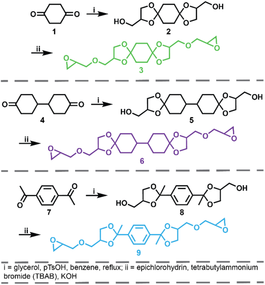
The synthetic route for the preparation of the ketal-based bisepoxide monomers is shown in Fig. 1. The synthesis of these monomers entailed two consecutive reactions: an initial acid-catalyzed ketalization of the diketones (1, 4, or 7) and glycerol, yielding the alcohol-terminated intermediate products (2, 5, or 8), followed by a base-catalyzed glycidylation, resulting in the formation of the bisepoxide monomers 3, 6, and 9. The acid-catalyzed ketalization reaction is highly favorable due to the cyclization of the diol and ketone species. The alcohol-terminated intermediate products 2, 5, and 8 were obtained with yields of 73.9%, 81.0%, and 77.1%, respectively. The purity of the intermediate alcohol products, typically ranging from 92% to 98% following workup, was confirmed by 1H and 13C-NMR (2, Fig. S1;†5, Fig. S2;†8, Fig. S3†). These intermediates were used in subsequent reactions without further purification. The subsequent glycidylation was carried out using a well-known biphasic base-catalyzed reaction between the intermediate alcohol products and epichlorohydrin using a phase transfer catalyst. The reaction temperature was carefully maintained below 25 °C during the addition of base to prevent a violent exotherm. This precaution is particularly important when scaling up these reactions. Upon stabilization of the reaction temperature, the mixture was allowed to stir at room temperature. The progress of the reaction was monitored via1H-NMR, specifically by integrating the epoxide functional peaks at 2.61/2.79 ppm (terminal CH2) and 3.14 ppm (CH). Although the crude product obtained directly from the workup was adequately pure for polymerization, additional purification was performed using flash column chromatography. This process yielded clear, viscous oils for all three products, with yields of 66.0% for product 3, 74.4% for product 6, and 47.6% for product 9. 1H and 13C-NMR spectra for these monomers are provided in Fig. S4–S6.†
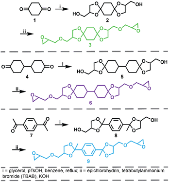 |
| | Fig. 1 Synthesis of ketal bisepoxide monomers 3, 6, and 9 from commercially available diketones. | |
Epoxy-amine ketal thermoset synthesis and characterization
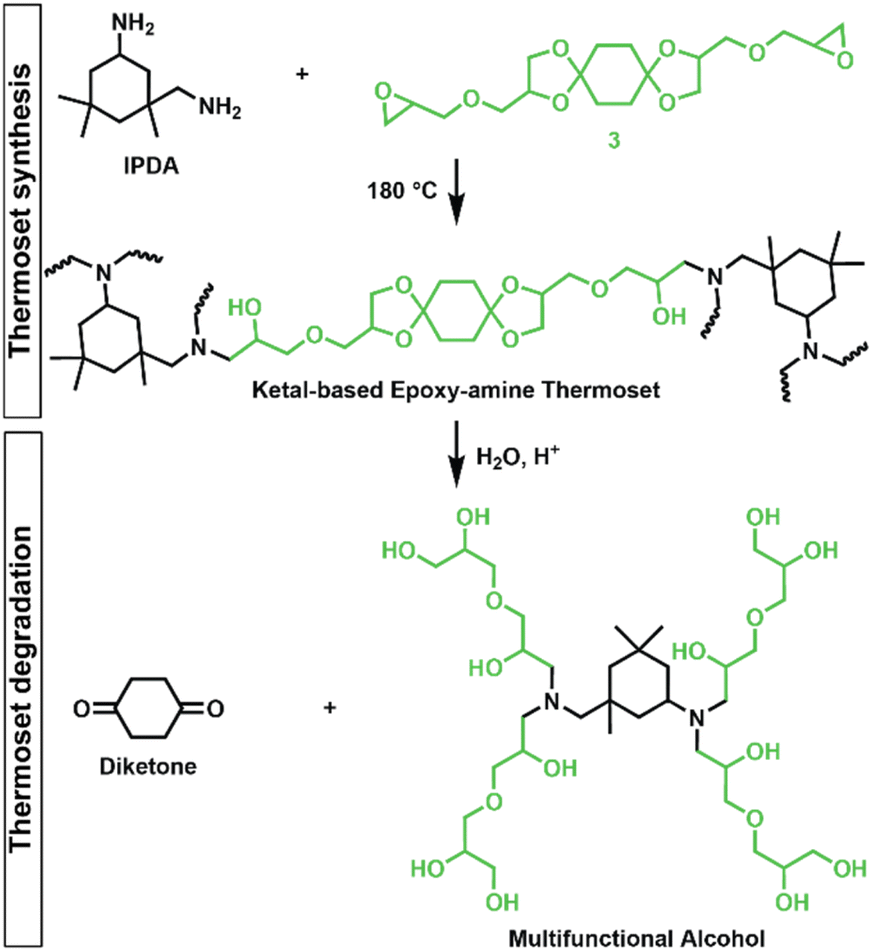
Epoxy-amine ketal thermosets were synthesized from the library of ketal-based bisepoxide monomers 3, 6, and 9 using isophorone diamine (IPDA), as illustrated in Fig. 2. These polymer thermosets are denoted as 3P, 6P, and 9P. In addition to our degradable thermoset library, a non-degradable thermoset denoted as HP was synthesized using commercially available hydrogenated diglycidyl ether bisphenol-A (Eponex 1510™ by Hexion) and IPDA to compare thermomechanical and physical properties. For all cases, IPDA was the amine hardener of choice due to its liquid state, which facilitated optimal mixing with the bisepoxide monomers used in this investigation. In a standard thermoset preparation, the bisepoxide monomer and IPDA were combined in a 2![[thin space (1/6-em)]](https://www.rsc.org/images/entities/char_2009.gif) :1 molar ratio, mixed using a vibratory mixer, and subsequently degassed under vacuum. The degassed resin was then transferred into silicone molds and subjected to a stepwise curing process in an oven: initially at 75 °C for 2 h, followed by 120 °C for 2 h, and finally at 180 °C for 2 h.
:1 molar ratio, mixed using a vibratory mixer, and subsequently degassed under vacuum. The degassed resin was then transferred into silicone molds and subjected to a stepwise curing process in an oven: initially at 75 °C for 2 h, followed by 120 °C for 2 h, and finally at 180 °C for 2 h.
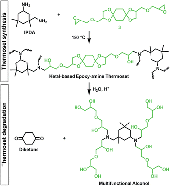 |
| | Fig. 2 Synthesis of epoxy-amine ketal thermosets from monomer 3/IPDA and degradation into diketone and multifunctional alcohol by-products (drawn as idealized structure that would be derived from quantitative hydrolysis of a fully converted epoxy-amine network). | |
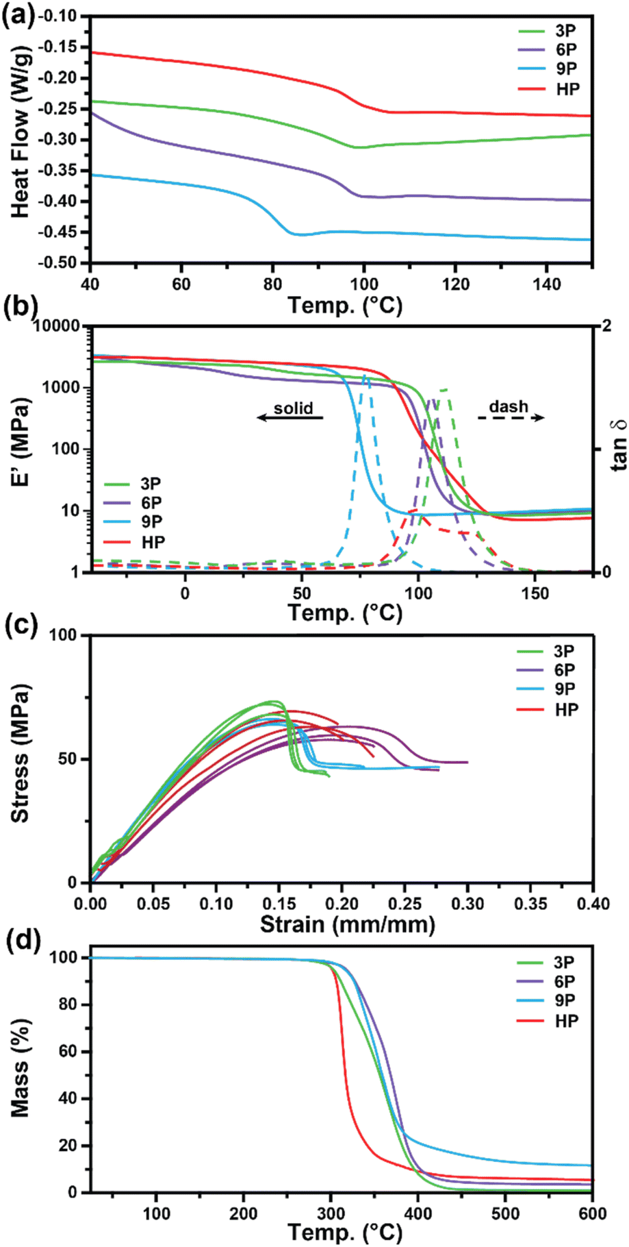
Differential scanning calorimetry (DSC) and dynamic mechanical analysis (DMA) were employed to investigate the glass transition temperatures (Tg) of the networks to determine the ultimate use temperatures of the degradable ketal-based networks compared to the commercially available HP thermoset. As depicted in Fig. 3a, DSC analysis revealed a single second-order endotherm in the thermogram for each polymer network, indicative of the Tg. The determined Tgs were 94.1 °C for 3P, 96.3 °C for 6P, and 80.7 °C for 9P. The tanδ (E′′/E′) and storage moduli (E′) curves obtained by DMA for thermosets 3P–9P are provided in Fig. 3b. The mechanical Tg, taken as the peak of the tanδ curve, was observed at 111 °C for 3P, 105 °C for 6P, and 86.3 °C for 9P, and the HP network at 107 °C. 9P exhibited a consistently lower Tg than the other thermoset compositions, which may be attributed to the additional degree of rotation from the para-positioned σ-bonds of monomer 9. Likewise, monomers 3 and 6 have tricyclic and bicyclic structures, respectively, that tend to increase network rigidity and Tg. The network structure was determined to be homogenous with all ketal-based networks displaying narrow tanδ peaks; the only exception being HP, which exhibited a bimodal peak that is presumably due to mixed aromatic and aliphatic network composition due to incomplete hydrogenation of the monomer (Fig. 3a and Table 1). While the structure of the ketal monomer influenced Tg, it had relatively little effect on the glassy and rubbery moduli, as indicated in Fig. 3b. Fig. 3c presents the stress–strain curves for the epoxy-amine thermosets, with the corresponding mechanical data quantified in Table 1. The 3P and 9P thermosets demonstrated the highest Young's modulus values, at 632 ± 36 and 676 ± 12 MPa, respectively. In contrast, the 6P network exhibited the lowest Young's modulus, at 462 ± 10 MPa. These trends in tensile properties align well with the glassy storage moduli trends observed via DMA and the properties were comparable to those of the HP network. All samples exhibited some degree of yield after peak stress typical of some epoxy-amine thermosets.28 Notably, the 6P network, characterized by its bicyclohexyl structure, displayed the greatest strain at break and toughness. This can be attributed to a distortional energy-absorbing mechanism, which arises from conformational changes such as chair/boat ring flips in the cyclohexyl linkages.29 Similar trends were previously observed with this bicyclohexyl structure in thiol–ene photopolymer networks.25
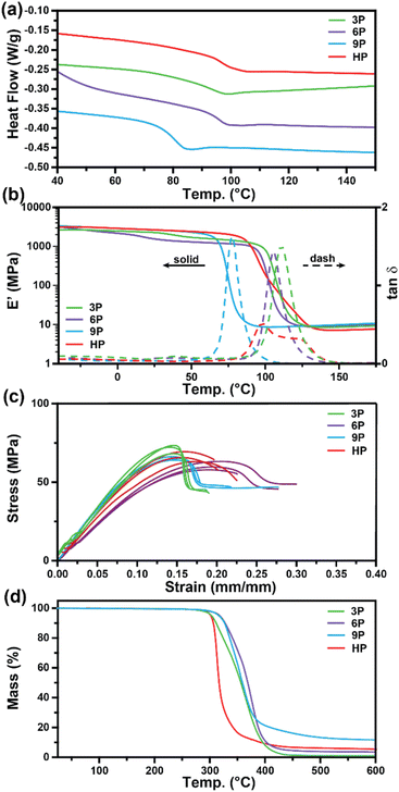 |
| | Fig. 3 Characterization of 3P, 6P, 9P, and HPvia (a) DSC, (b) DMA, (c) mechanical testing, and (d) TGA. | |
Table 1 Summary of mechanical, thermomechanical and thermal degradation data for ketal-based thermosets
| |
3P
|
6P
|
9P
|
HP
|
| Young's modulus (MPa) |
632 ± 35.6 |
462 ± 9.94 |
676 ± 12.3 |
583 ± 32.4 |
| Strain at break (mm mm−1) |
0.181 ± 0.014 |
0.267 ± 0.038 |
0.225 ± 0.049 |
0.208 ± 0.015 |
| Peak stress (MPa) |
71.2 ± 2.77 |
60.3 ± 2.69 |
65.1 ± 1.10 |
66.1 ± 3.17 |
|
T
g DSC (°C) |
94.1 |
96.3 |
80.7 |
96.8 |
|
T
g DMA (°C) |
111 |
105 |
78 |
107 |
| Glassy modulus (MPa, 25 °C) |
2264 |
1552 |
2651 |
2645 |
| Rubbery modulus (MPa, 150 °C) |
8.62 |
9.23 |
11.4 |
9.46 |
| FWHM (tanδ) |
15.6 ± 0.213 |
14.1 ± 0.170 |
11.9 ± 0.155 |
N/A (bimodal) |
|
T
d, 10% (°C) |
311 |
327 |
326 |
306 |
Thermogravimetric analysis was utilized to assess the thermal stability of the ketal-based epoxy-amine thermosets under air atmosphere. The thermal degradation profiles for each thermoset, depicted in Fig. 3d, exhibited similar behavior, demonstrating a relatively high resistance to thermal degradation. The temperature at which a 10% mass loss (Td,10) occurred ranged from 311 °C to 327 °C (Table 1). All samples displayed a single mass loss transition, with degradation leaving less than 15% char beyond 500 °C.
CFRP construction and mechanical testing
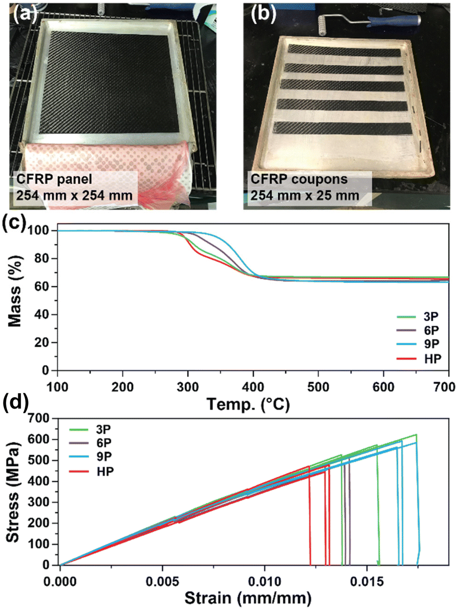
CFRP laminates (3 layers of 3k 2 × 2 carbon fiber twill weave oriented in alternating 0° and 90° orientations) were prepared via a conventional hand-laminating/vacuum bagging technique using the three degradable ketal-based epoxy monomers 3–9 with IPDA, along with HP to compare the overall mechanical properties. An exemplar CFRP panel is shown in Fig. 4a. Each panel was then cut into 25 mm × 254 mm strips for mechanical testing in accordance with ASTM D3039 (Fig. 4b). The resin-to-fiber weight ratio was maintained to enable a direct comparison of mechanical performance. Prior to mechanical testing, TGA was employed to analyze samples from each panel to calculate the final resin loading after cure and post-processing. Given that carbon fibers are thermally stable up to approximately 800 °C,30 TGA experiments were conducted up to 700 °C to pyrolyze the matrix and ascertain the matrix-to-fiber weight ratio of each CFRP. The onset of matrix degradation occurred around 300 °C, mirroring the behavior of the resin without carbon fiber (Fig. 3d). The resin-to-fiber ratio for all panels was found to be similar and within the typical range for CFRPs,31,32 with resin loading amounts of 33.4% for 3P CFRP, 36.0% for 6P CFRP, 36.9% for 9P CFRP, and 34.6% for HP CFRP (Fig. 4c). Given the minimal differences among the panels, a direct comparison of mechanical properties was feasible.
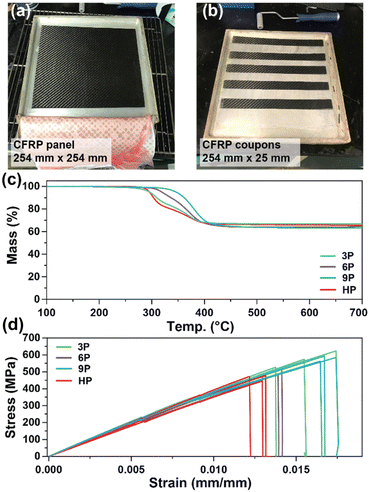 |
| | Fig. 4 (a and b) Photos of CFRP composite panel (254 mm × 254 mm) prepared and cut (25 mm × 254 mm) for mechanical testing. (c) Thermogravimetric analysis to determine resin-to-fiber ratio after composite cure and processing. (d) Stress–strain curves for CFRP composites. | |
Fig. 4d shows the stress vs. strain curves for each CFRP composition in triplicate, with average values provided in Table 2. 3P CFRP and 9P CFRP exhibited the highest Young's modulus at 44.6 ± 1.9 GPa and 46.6 ± 4.6 GPa – generally reflecting the trends observed in mechanical properties for the resin only samples. However, similar Young's modulus values were observed for all composite compositions, which can be attributed to a mechanical response dominated by the longitudinal tensile properties of the vertically aligned fibers within the samples. The degradable ketal-based CFRPs generally surpassed the HP control in terms of average strain at break and ultimate tensile strength. Notably, 9P CFRP demonstrated the highest strain at break (0.0169 ± 0.000488 mm mm−1) and the highest tensile strength (584.7 ± 12.9 MPa). Although numerous factors influence the mechanical performance of CFRPs,33 the superior performance of 9P CFRP may be attributed to enhanced matrix–fiber interactions facilitated by the aromatic content of the 9P resin.
Table 2 Mechanical properties of the 3P–HP CFRP composites
| Sample |
Young's modulus (GPa) |
Strain at break (mm mm−1) |
Tensile strength (MPa) |
|
3P CFRP |
44.6 ± 1.9 |
0.0156 ± 0.0017 |
550.7 ± 25.1 |
|
6P CFRP |
39.9 ± 1.8 |
0.0137 ± 0.0006 |
493.9 ± 20.3 |
|
9P CFRP |
46.6 ± 4.6 |
0.0169 ± 0.0005 |
584.7 ± 12.9 |
|
HP CFRP |
41.8 ± 3.9 |
0.0128 ± 0.0005 |
465.9 ± 15.5 |
Thermoset degradation
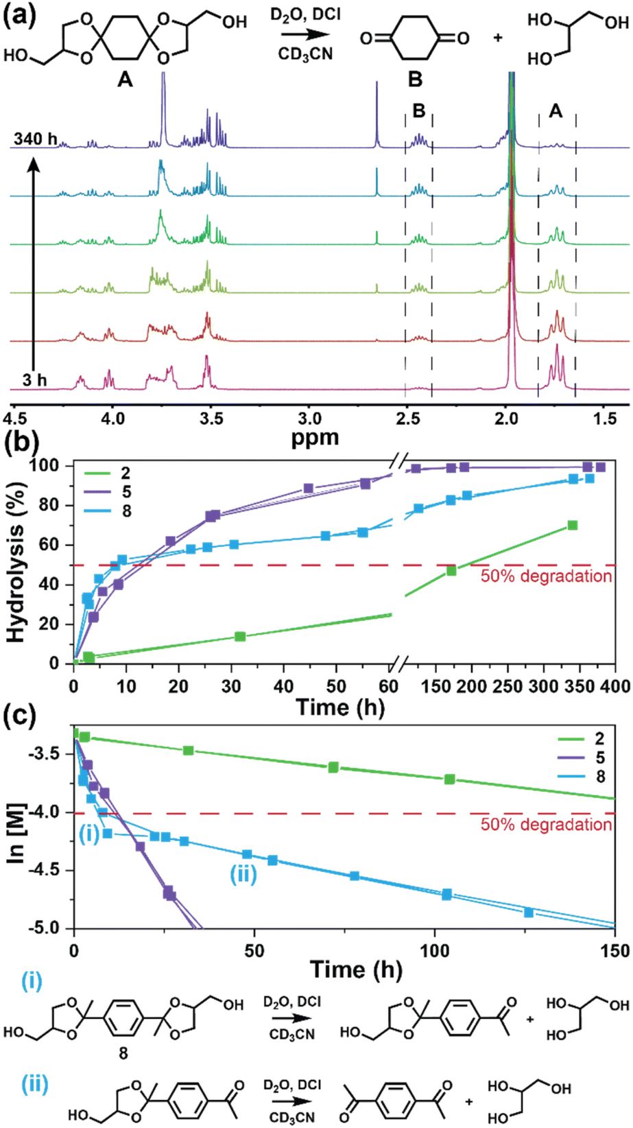
The degradation of the ketal-based thermosets is depicted in Fig. 2 (with further elaboration in Fig. 7). To discern the impact of ketal structure on hydrolytic stability of the monomers independent of influences such as polymer network architecture and hydrophobicity,34–36 evaluation of degradation kinetics were initially conducted on intermediate products 2, 5, and 8 using 1H-NMR. Here, we used the alcohol intermediates as surrogates for the monomers to circumvent complications in the observed kinetics that could arise from the acid-catalysed ring-opening of the monomer epoxide groups.37Fig. 5a presents the time-dependent 1H-NMR spectra for the hydrolysis of intermediate 2. The extent of hydrolysis over time was quantified by comparing the ratio of the ketal (indicated by peak label A) and ketone (indicated by peak label B) peaks. The kinetic curves obtained from these time-resolved NMR spectra are shown in Fig. 5b. Below 50% hydrolysis, we observed the expected trend in ketal stability with 2 exhibiting the greatest stability (and thus slowest rate of hydrolysis), followed by 5 and 8 – results that are in good agreement with our previous work with poly(β-thioether ester ketals).25 However, beyond 50% hydrolysis, the kinetic curves for 5 and 8 intersect, suggesting a change in hydrolytic stability of these ketal structures. This abrupt change in kinetics is more apparent by plotting the natural log of the ketal concentration vs. time (Fig. 5c). Unlike ketals 2 and 5, which both exhibit pseudo-first order degradation kinetics characterized by a single linear kinetic regime (k2 = 0.357 ± 0.001 h−1 × 10⁻², k5 = 4.24 ± 0.137 h−1 × 10⁻²), ketal 8 exhibits two distinct linear regimes – one before and another after 50% hydrolysis, denoted as (i) and (ii), respectively, as illustrated in Fig. 5c. The distinct kinetic regimes for 8 can be explained by resonance effects of the aromatic group before and after the hydrolysis of at least one ketal substituent on the aromatic ring. Substituent effects on the rates of hydrolysis of acetals and ketals have been well established,38–41 where steric26,42 and electronic effects27,43,44 have a major influence over ketal/acetal stability. For instance, electron donating groups help stabilize the transition state of the well-established acid-catalyzed hydrolysis mechanism – resulting in more rapid hydrolysis while electron withdrawing groups destabilize the transition state, slowing hydrolysis.27 In the case of ketal 8, the presence of a ketal substituent in the para position helps to stabilize the transition state – affording relatively quick hydrolysis of the first para-substituted ketal (k8(i) = 8.03 ± 0.08 h−1 × 10⁻²). The resultant asymmetric para-substituted ketone then destabilizes the carbocation transition state through resonance – decreasing the hydrolysis rate of the second ketal by an order of magnitude (k8(ii) = 0.600 ± 0.036 h−1 × 10⁻²).
 |
| | Fig. 5 (a) Time-resolved 1H-NMR spectra for the hydrolysis of intermediate 2 by monitoring the integration of (A) ketal and (B) ketone peaks over 340 h at ambient temperature (20 °C). (b) Hydrolysis kinetics plotted for 2, 5, and 8vs. time. (c) Semilogarithmic kinetic plot for the hydrolysis of 2, 5, and 8. Two kinetic regimes and the associated structures for hydrolysis of 8 are indicated by (i) and (ii). | |
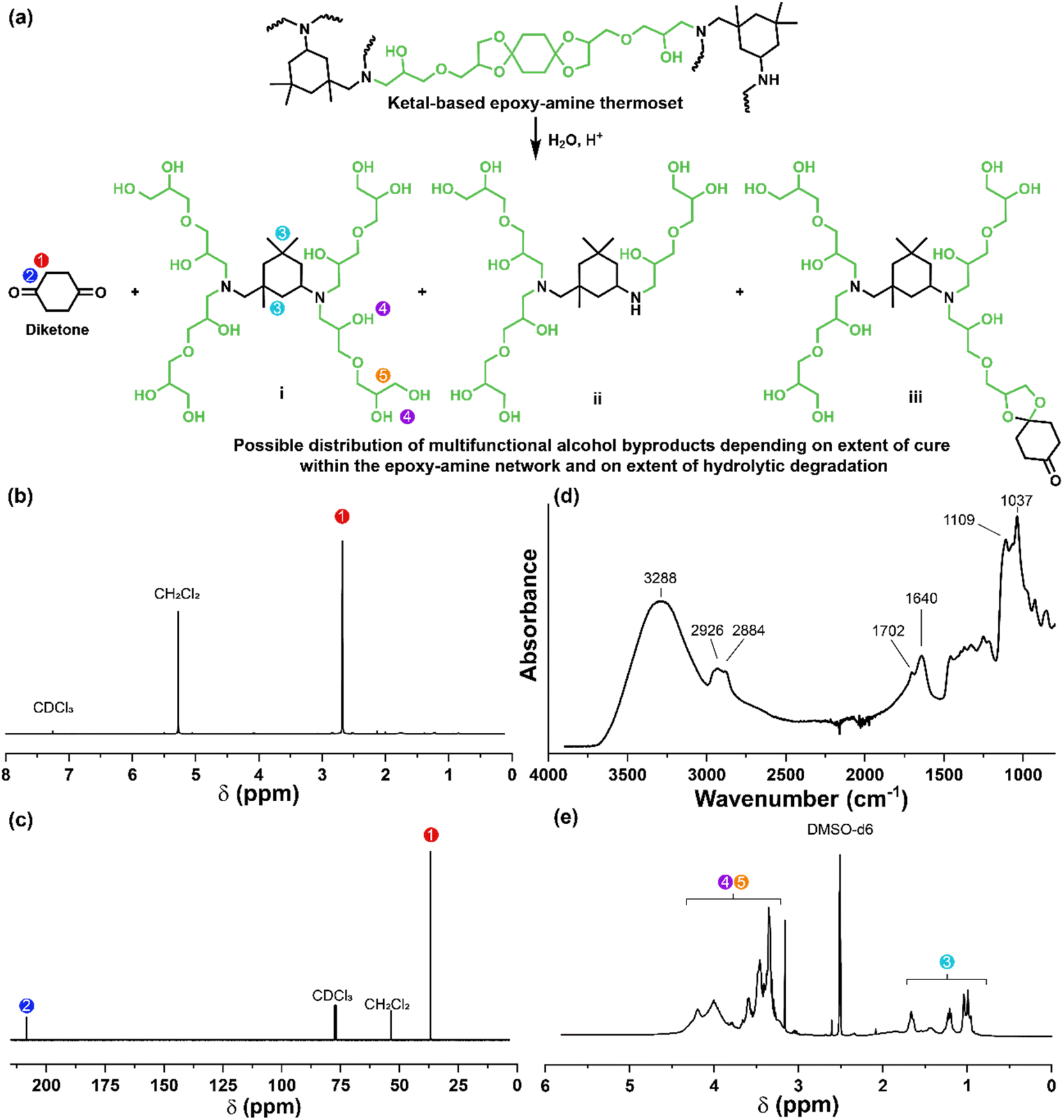
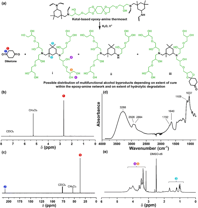
The influence of ketal structure on the hydrolytic stability of thermosets, as suggested by the previous hydrolysis kinetics of the small molecule intermediates, was further investigated through mass-loss experiments conducted in various aqueous environments. These included 1 M HCl (pH 0.88), acetate buffer (pH 4.07), phosphate buffered solution (PBS) (pH 7.40), and glycine/NaOH buffer (pH 11.65). The results of these mass-loss experiments are shown in Fig. 6a–d. Across the mildly acidic to basic pH solutions (4.07–11.65), negligible losses in mass were observed over 800 hours, indicating 3P, 6P, and 9P thermosets are relatively stable under such conditions. Only when submerged in highly acidic 1 M HCl did the samples exhibit rapid mass loss (Fig. 6d). The trend in thermoset hydrolytic stability mirrored that of our small molecule degradation experiments, with 3P exhibiting the slowest degradation and 9P and demonstrating the fastest degradation. Static water contact angle measurements of the thermosets were similar (Fig. S7,† 90.3° for 3P, 88.5° for 5P, and 93.8° for 9P), suggesting that hydrophobicity of resins play a minimal role in the observed degradation profiles. All samples displayed surface-controlled erosion behavior, evidenced by consistent mass-loss profiles and retention of shape with a reduction in sample dimensions throughout the degradation process (Fig. 6e). This surface erosion behavior is a result of ketal bond cleavage occurring at a faster rate than the diffusion of solution into the bulk of the sample.34 Importantly, the degradation by-products for each sample were sufficiently miscible in the aqueous degradation media to preclude the use of organic cosolvents (e.g. THF, DMF, etc.), which are often necessary to facilitate efficient degradation of polymer thermosets. We gained additional insights into the composition of the degradation byproducts for 3P by performing an organic extraction (CH2Cl2) of the aqueous degradation media (Fig. 7a). After separation of the layers, the aqueous fraction was neutralized with NaHCO3 prior to lyophilization. As indicated by 1H (Fig. 7b) and 13C NMR (Fig. 7c), the organic fraction was identified as the monomer building block 1,4-cyclohexanedione. For simplicity, the multifunctional alcohol byproduct shown in Fig. 2 is drawn to represent an ideal structure derived from quantitative hydrolysis of a fully converted epoxy-amine network. However, the aqueous fraction likely contains a mixture of multifunctional alcohol structures better represented by the distribution of products (i–iii) shown in Fig. 7a (e.g., structure (ii) could arise from incomplete conversion of IDPA). FTIR of the lyophilized fraction, as shown in Fig. 7d, clearly indicates an aliphatic byproduct (2929, 2884 cm−1) that carries significant hydroxyl functionality, with a broad band at 3288 cm−1 and bands at 1037 and 1109 cm−1 consistent with primary and secondary alcohols of an alkyloxy-1,2-propanediol structure.45 The peak at 1702 cm−1 may be attributed to either residual 1,4-cyclohexanedione or to incomplete hydrolysis of the ketal yielding a functionality represented by structure (iii) in Fig. 7. 1H NMR of the lyophilized fraction points to similar structural features derived from an IPDA framework;46 however, due to the inability of effectively separate the products, only general NMR peak assignments were made. In previous work,25 we demonstrated the ability to recover the ketone building blocks for use in the synthesis of new monomer, thus we did not repeat those experiments for the current work. While speculative at best, the multifunctional alcohol byproducts may find use as polyol synthetic additives or as precursors for biolubricants.47
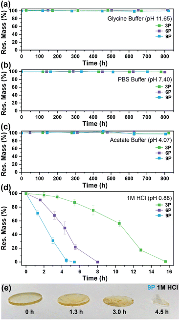 |
| | Fig. 6 Mass-loss degradation versus time for 3P, 6P, and 9P in (a) glycine buffer (pH 11.65), (b) PBS buffer (pH 7.40), (c) acetate buffer (pH 4.07), and (d) 1 M HCl (pH 0.88). Experiments were conducted at ambient lab temperature (20 °C). (e) Snapshot photos of 9P disks pulled from 1 M HCl at various time intervals to illustrate surface erosion. | |
 |
| | Fig. 7 (a) Degradation of thermoset 3P under acidic aqueous conditions to yield 1,4-cyclohexanedione and a mixture of multifunctional alcohol structures. (b) 1H NMR of 1,4-cyclohexanedione obtained from the organic phase. (c) 13C NMR of 1,4-cyclohexanedione obtained from the organic phase. (d) FTIR of the multifunctional alcohol mixture obtained after lyophilization of the neutralized aqueous phase. (e) 1H NMR of the multifunctional alcohol mixture; due to the inability to separate the products, only general NMR peak assignments are made. | |
CFRP stability, degradation, and fiber recovery
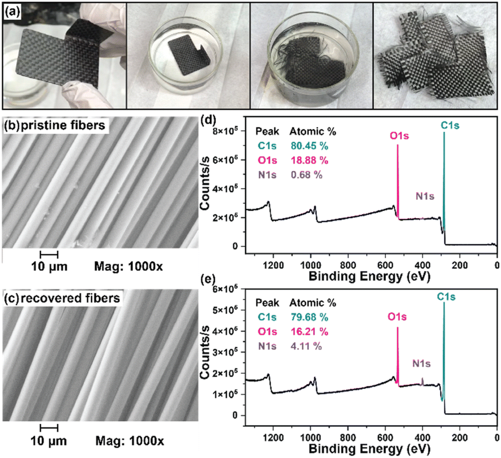
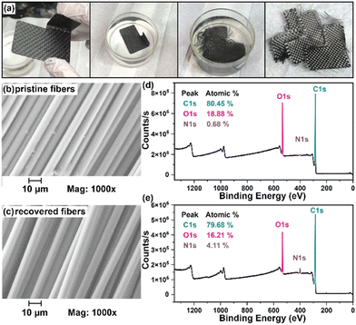
While numerous strategies for thermoset degradation and carbon fiber recovery have been reported in the literature, most of these methods rely on a combination of organic solvents (e.g., DMF,48 THF,49 methanol,14 acetone,7,17etc.) and aqueous acid or base to effectively degrade the polymer matrix. These approaches, while effective, often introduce additional complexities and environmental concerns. Here, we demonstrate an approach that leverages an entirely aqueous acidic solution for carbon fiber recovery. As a demonstration, a small 3-layer CFRP part was fabricated using 6P and 1k plain weave carbon fiber weave following the same composite preparation methods as previously mentioned (Fig. 8a). The 6P CFRP laminates were submerged in 1 M HCl for 12 h to ensure complete degradation of the matrix (Fig. 8a). Upon removal from the 1 M HCl bath, the recovered carbon fiber weaves were easily separated (Fig. 8a), soaked in a DI H2O bath multiple times, and dried in a 60 °C incubation oven. Fig. 8b and c show the SEM micrographs of the pristine and recovered fibers, respectively. In both cases, the surface morphology is smooth and free of noticeable defects at 1000× magnification. The XPS survey spectrum of the pristine carbon fibers is shown in Fig. 8d indicating the presence of carbon (C 1s, 80.45 at%), oxygen (O 1s, 18.88 at%), and nitrogen (N 1s, 0.68 at%). XPS analysis of the carbon fiber recovered after degradation of the 6P matrix, as shown in Fig. 8e, revealed a similar elemental composition with a small increase in the nitrogen content, likely due to residual polymer degradation by-products. Considering the simplicity of the recovery process (e.g., fiber weaves were simply soaked in DI water with minimal agitation as to not disrupt the weave), the recovered fibers were remarkably clean and unperturbed.
 |
| | Fig. 8 (a) Degradation of a 6P CFRP laminate part via submersion in 1 M HCl showing full dissolution of the polymer matrix and separation of carbon fiber layers after washing with DI water and drying. SEM of (b) pristine carbon fibers and (c) carbon fibers recovered after polymer thermoset hydrolysis. XPS survey analysis of (d) pristine and (e) recovered carbon fibers. | |
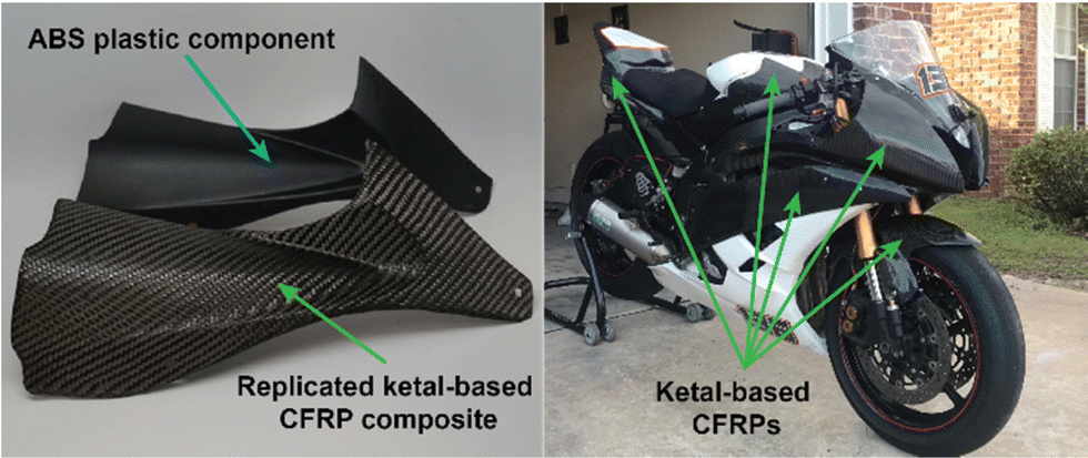
In the previous section, we demonstrated the hydrolytic stability of the ketal-based epoxy-amine thermosets, which remained stable for over 800 hours in conditions ranging from pH 4 to pH 12 but rapidly degraded at pH 1. Additionally, we demonstrated the ability to induce degradation of the polymer matrix and recovery of near-pristine carbon fibers using entirely aqueous conditions. To illustrate the practical application of these ketal-based epoxy-amine thermosets, we fabricated CFRP composites to replace several acrylonitrile butadiene styrene (ABS) plastic components on first author Alameda's motorcycle (Fig. 9). This real-world application served as a rigorous test of durability and performance of these ketal-based CFRPs under demanding conditions (weather, temperature, etc.). Albeit a qualitative assessment, the ketal-based CFRP components have shown no signs of degradation, either in appearance or performance after two years of use. This successful application underscores the potential of these ketal-based epoxy-amine thermosets for use in high-performance applications, clearly illustrating opportunities to balance durability and end-of-life recyclability.
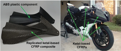 |
| | Fig. 9 (left) Photo of a ketal-based CFRP composite replicated from an original ABS motorcycle component and install. Multiple ketal-based CFRP components were installed on the motorcycle shown (right) and have been field tested approximately two years (at time of manuscript submission). | |
Conclusions
This work demonstrates the successful synthesis and application of degradable epoxy-amine thermosets using novel cyclic-ketal based bisepoxide monomers. These thermosets, exhibiting robust mechanical and thermomechanical properties, provide a promising alternative to non-degradable commercial epoxy-amine thermoset for a broad range of applications. Importantly, the ability to completely degrade these thermosets in low pH conditions enables the recovery of pristine carbon fibers from CFRPs and the potential to recover and reuse ketone building blocks. The findings underscore the potential utility of cyclic-ketal based thermosets in the fabrication of recyclable CFRP composites clearly illustrating the possibility of achieving balance between real-world application and effective end-of-use carbon fiber recovery strategies.
Experimental
Materials
All reagents were obtained commercially and used without further purification unless otherwise specified. 1,4-Cyclohexanedione, 4,4′-bicyclohexanone, 1,4-diacetylbenzene, and isophoronediamine were sourced from TCI Chemical. Tetrabutylammonium bromide (TBAB), epichlorohydrin (EPH), benzene, glycerol, p-toluenesulfonic acid (p-TsOH) were sourced from Sigma-Aldrich. Potassium hydroxide, 1 M HCl, PBS buffer, glycine, acetic acid, sodium acetate, and other solvents were sourced from Fisher Scientific. 3k 2 × 2 twill weave and 1k plain weave carbon-fiber cloths were supplied from Toray. Hydrogenated diglycidyl ether bisphenol-A (HDGB/Eponex™ 1510) was supplied from Hexion. Deuterated solvents were sourced from Acros.
Monomer characterization
Monomer structure and purity were confirmed using 1H-NMR, 13C-NMR experiments using a Bruker Avance™ 600 and 400 MHz spectrometers. NMR samples were prepared in either deuterated chloroform or deuterated dimethyl sulfoxide. Additionally, monomer structure was confirmed by mass spectrometry using a Bruker 12 Tesla APEX-Qe FTICR-MS in positive-ion mode ionization with an Apollo II ion source.
Synthesis of monomer 3
30.0 g (0.27 mol) of 1,4-cyclohexanedione (1) was added to a 250 mL RBF with 65.0 g (0.71 mol) glycerol, a catalytic amount of p-TsOH, and 150 mL benzene. The reaction was purged under a constant flow of N2 and refluxed using a Dean–Stark trap to collect water. The extent of the reaction measured via the total water produced from the reaction. Once the reaction was complete, it was allowed to cool to room temperature with 4 mL of triethylamine added to quench the p-TsOH. The benzene was then removed from the reaction using a rotary evaporator with 100 mL ethyl acetate added back to the reaction to redissolve the product. The reaction was then washed 3× with DI water and 3× with brine. The aqueous layer was extracted 3× with ethyl acetate and combined with the remaining organic layer and dried using sodium sulfate. The excess solvent was removed under vacuum to yield 51.3 g (0.20 mol) of a yellowish, viscous oil (intermediate product 2, yield: 73.9%). NMR characterization of the purified intermediate 2 is provided in the ESI† and is in agreement with data previously reported by Lingier et al.50 and Hu et al.51 Without further purification, 30 g (0.12 mol) of 2 was then added to a 500 mL RBF with 55.6 g (0.60 mol) EPH and 3.00 g (0.009 mol) TBAB and stirred at 100 °C for 5 h after which the solution turned a pale yellowish color. The reaction was cooled to 0 °C in an ice bath under mechanical overhead stirring. Once cooled a 50:50 KOH:H2O solution was added dropwise while stirring and allowed to stir for 72 h. The reaction was filtered to remove the KCl precipitate and then washed 3× with DI H2O and 3× with brine, dried with sodium sulfate, and placed under reduced pressure at 40 °C to remove solvent and excess EPH to yield crude monomer 3. Purification by column chromatography (15:85 hexane:ethyl acetate) was used to purify the final product to yield 29.5 g (0.8 mol) of a clear oil (yield: 66.0%). HRMS: calcd for C18H28O8Na+ [M + Na]+m/z: 395.167639, measured: 395.167319. 1H NMR (600 MHz, CDCl3) δ 4.31–4.24 (m, 2H), 4.05 (ddt, J = 8.2, 6.4, 1.6 Hz, 2H), 3.84 (t, J = 2.7 Hz, 0.5H), 3.84–3.81 (m, 1H), 3.80 (dd, J = 2.9, 1.1 Hz, 0.5H), 3.75 (ddd, J = 9.6, 8.3, 6.3 Hz, 2H), 3.63 (dd, J = 10.1, 5.5 Hz, 1H), 3.57 (dd, J = 5.5, 2.0 Hz, 2H), 3.54–3.49 (m, 1H), 3.48–3.39 (m, 2H), 3.15 (dtq, J = 5.8, 2.9, 1.4 Hz, 2H), 2.80 (ddd, J = 5.2, 4.2, 1.4 Hz, 2H), 2.61 (dq, J = 4.9, 2.5 Hz, 2H), 1.91–1.70 (m, 8H). 13C NMR (151 MHz, CDCl3) δ 108.93 (C), 74.39 (CH), 72.25 (CH2) 72.14 (CH2), 66.33 (CH2), 50.64 (CH), 43.91 (CH2), 33.33 (CH2), 31.84 (CH2).
Synthesis of monomer 6
15.3 g (0.079 mol) of 4,4′-bicyclohexanone (4) was added to a 250 mL RBF with 23 g (0.25 mol) glycerol, a catalytic amount of p-TsOH, and 80 mL benzene. The reaction was purged under a constant flow of N2 and refluxed using a Dean–Stark trap to collect water. The extent of the reaction measured via the total water produced from the reaction. Once the reaction was complete, it was allowed to cool to room temperature with 5 mL of triethylamine added to quench the p-TsOH. The benzene was then removed from the reaction using a rotary evaporator with 100 mL ethyl acetate added to redissolve the product. The reaction was then washed 3× with DI H2O, 3× with brine and dried using sodium sulfate. The excess solvent was removed under vacuum to yield 22.07 g (0.064 mol) of pure intermediate product 5, a white powder (yield 81.0%). 10.0 g (0.029 mol) of intermediate product 5 was then added to a 250 ml RBF with 42.1 g (0.45 mol) EPH and 1.00 g (0.003 mol) TBAB was stirred at 100 °C for 5 h. The reaction was then cooled to 0 °C in an ice bath under mechanical stirring. Once cooled a 50:50 KOH:H2O solution was added dropwise with mechanical overhead stirring and allowed to stir for 48 h. The reaction was filtered to remove the KCl precipitate and then washed 3× with H2O and 3× with brine, dried with sodium sulfate, and placed under reduced pressure at 40 °C to remove solvent and excess EPH to yield crude monomer 6. Purification by column chromatography (15:85 hexane:ethyl acetate) was used to purify the final product to yield 9.81 g (0.021 mol) of a clear oil (yield: 74.4%). HRMS: calcd for C24H38O8Na+ [M + Na]+m/z: 477.245889, measured: 477.245856. 1H NMR (600 MHz, CDCl3) δ 4.35–4.18 (m, 2H), 4.10–3.99 (m, 2H), 3.88–3.67 (m, 4H), 3.67–3.37 (m, 6H), 3.21–3.09 (m, 2H), 2.80 (q, J = 4.2 Hz, 2H), 2.67–2.56 (m, 2H), 1.87–1.76 (m, 2H), 1.76–1.65 (m, 6H), 1.65–1.52 (m, 2H), 1.43 (dtd, J = 26.0, 13.1, 4.0 Hz, 2H), 1.37–1.20 (m, 4H), 1.14 (tdd, J = 10.6, 6.0, 2.8 Hz, 2H) ppm. 13C NMR (151 MHz, CDCl3) δ 110.08 (C), 74.29 (CH), 72.19 (CH2), 66.47 (CH2), 50.77 (CH2), 44.13 (CH), 41.20 (CH2), 35.97 (CH), 34.45 (CH2), 27.15 (CH2).
Synthesis of monomer 9
20.4 g (0.126 mol) of 1,4-diacetylbenzene (7) was added to a 500 mL RBF with 25.8 g (0.280 mol) glycerol, a catalytic amount of p-TsOH, and 175 mL benzene. The reaction was purged under a constant flow of N2 and refluxed using a Dean–Stark trap to collect water. The extent of the reaction measured via the total water produced. Once the reaction was complete, it was allowed to cool to room temperature and 5 ml of triethylamine added to quench the p-TsOH. The reaction was then washed 3× with DI water and 3× with brine and dried using sodium sulfate. The excess solvent was removed under vacuum to yield 30.1 g (0.097 mol) (77.07% yield) of intermediate product 8, a yellowish viscous oil. All of 8 was then added to a 500 ml RBF with 89.0 g (0.99 mol) EPH, 1.5 g (0.005 mol) TBAB, and cooled to 0 °C in an ice bath under mechanical stirring. Once cooled 40 mL of a 50:50 KOH:H2O solution was added dropwise while stirring and allowed to react for 48 h. The reaction was filtered to remove the KCl precipitate, 40 mL of dichloromethane (DCM) was added to the reaction and then washed 3× with H2O and 3× with brine, dried with sodium sulfate and put under reduced pressure at 40 °C to remove solvent and excess EPH to yield crude monomer 9. Purification by column chromatography (15:85 hexane:ethyl acetate) was used to purify the final product (yield: 19.5 g, 47.6%), a clear viscous oil. HRMS: calcd for C22H30O8Na+ [M + Na]+m/z: 445.183289, measured: 445.183002. 1H NMR (400 MHz, CDCl3) δ 7.55–7.36 (m, 4H), 4.50–4.38 (m, 0.5H), 4.25–4.09 (m, 2H), 3.93–3.29 (m, 11.5H), 3.27–3.02 (m, 2H), 2.79 (dt, J = 19.4, 4.6 Hz, 1H), 2.70–2.51 (m, 2H), 1.73–1.47 (m, 2H). 13C NMR (151 MHz, CDCl3) δ 143.90 (C), 125.3 (CH), 109.10 (C), 74.90 (CH), 72.25 (CH2), 67.76 (CH2), 66.10 (CH2), 51.10 (CH), 44.66 (CH2), 28.00 (CH3) ppm.
Monomer hydrolysis kinetics
Hydrolysis kinetics for products 2, 5, and 8 were measured via in situ1H-NMR experiments at ambient temperature (20 °C). Each monomer was prepared as a 0.01 M CD3CN stock solution where 0.6 mL of solution was added to separate NMR tubes. 1H-NMR spectra were taken of each to establish a t0 data point after which. 0.2 mL of 0.01 M DCl solution was then added to each NMR tube to initiate hydrolysis. Total hydrolysis for each monomer was tracked by measuring the relative differences in ketal and ketone by-product peak integrations over time.
Epoxy-amine thermoset synthesis
Epoxide monomers where mixed 2:1 (mol) with IPDA, using a vibratory mixer and then subsequently degassed to remove any air bubbles. The mixture was then added to a PDMS mold and cured at 75 °C for 2 h, 120 °C for 2 h, and then post cured at 180 °C for 2 h. Each thermoset was allowed to cool slowly before being removed from the mold.
Mass-loss degradation experiments
Thermoset sample disks of 1 mm × 14 mm were individually weighed, placed in pre-weighed 20 mL vials, and immersed in degradation solution at ambient lab temperature (approximately 20 °C). At specific time intervals, samples would be decanted of their solution and washed with DI water 3× each. The vials containing the samples were then placed in a vacuum oven at 120 °C for 48 h to remove all water from the samples. The dry mass of each vial/sample was measured via microbalance and used to calculate sample mass and construct residual mass versus time plots. This process was repeated for each thermoset composition and degradation solution with each measurement repeated in triplicate. For the 3P sample, the aqueous degradation media was extracted with CH2Cl2. The organic phase was dried over MgSO4 and solvent was removed by rotary evaporation. The aqueous phase was neutralized with NaHCO3 and then lyophilized to remove water. FTIR of the lyophilized product was obtained on a Thermo Fisher Nicolet iS50.
Differential scanning calorimetry
DSC experiments were performed on a TA Instruments Q100™ for each thermoset composition using TA instruments Tzero™ aluminium pans. Experiments consisted of heat/cool/heat cycles from 25 °C to 160 °C using a 10.0 °C min−1 heating rate and 5.0 °C min−1 cooling rate.
Dynamic mechanical analysis
DMA experiments were performed on a TA Instruments Q800™ using samples of approximate dimensions of 20.0 mm × 5.00 mm × 1.00 mm (length × width × thickness). Experiments consisted of a temperature ramp from −40 °C to at least 160 °C using a constant frequency of 1.0 Hz, a strain rate of 0.05% and a 3.0 °C min−1 ramp rate in tension mode. All experiments were performed in triplicate to ensure consistent sample measurements.
Thermogravimetric analysis
TGA experiments were performed on a TA Instruments Q500™ using a platinum pan and thin film thermoset samples of approximately 10.0 mg each. Experiments consisted of a temperature ramp of 10 °C min−1 up to a final temperature of 600 °C in air atmosphere conditions.
CFRP laminate construction
CFRP laminate panels of 254 mm × 254 mm were constructed for all thermoset compositions using 3 layers of 3k 2 × 2 twill weave cloth oriented in alternating 0° and 90° orientations using a hand layup technique. The first layer was placed on an aluminum plate treated with PVA mold release, impregnated with resin and overlayed with subsequent layers using the same resin impregnation technique. The nominal fiber:resin weight ratio was set at 55:45. The materials was debulked, vacuum bagged at 25 in. Hg, and cured at 70 °C, 120 °C, and 180 °C (2 h for each temperature). Resin-to-fiber weight ratio was then measured for each panel using a burn-off method via TGA.52 This method assumes weight loss up to 700 °C is predominately attributed to the resin.
Mechanical testing of thermosets and CFRPs composites
Tensile testing was conducted for all thermoset compositions in accordance with ASTM D638 utilizing a type V tensile bar with a gauge length of 7.62 mm, gauge width of 3.18 mm and overall thickness of 1.25 mm. Samples were tested on an MTS Insight electromechanical test frame with a 500 N load cell at a constant crosshead speed of 1.5 mm min−1 to failure. Testing of each thermoset type was performed in triplicate to ensure consistent and accurate measurements. Mechanical testing of CFRP composites was carried out using based ASTM D3039 testing methods using an MTS Landmark Servohydraulic™ testing machine with 250 kN load cell and 1 inch gauge model 634.11 extensometer. Each CFRP panel was cut into 25 mm × 254 mm strips and tested in at least triplicate for each CFRP composition.
Carbon-fiber recovery
A cured composite laminate was fully submerged in a 1 M HCl bath for approximately 12 h until the matrix completely degraded and dissolved into solution. The recovered carbon fibers were removed from solution, washed extensively with DI water, and dried at 60 °C in an incubation oven prior to analysis. SEM was performed using a Zeiss Sigma VP™ scanning electron microscope. XPS analysis was performed using a Thermo-Fisher ESCALAB Xi+ spectrometer equipped with a monochromatic Al X-ray source (1486.6 eV, 300 mm2 spot size). Measurements were performed using the standard magnetic lens mode and charge compensation. The base pressure in the analysis chamber during spectral acquisition was 3 × 10⁻⁷ mBar. Spectra were collected at a takeoff angle of 90° from the plane of the surface. The pass energy of the analyzer was set at 20 eV for high-resolution spectra and 150 eV for survey scans, with energy resolutions of 0.1 eV and 1.0 eV, respectively. Binding energies were calibrated with respect to C 1s at 285.3 eV. All spectra were recorded using the Thermo Scientific Avantage software; data files were translated to VGD format and processed using the Thermo Avantage package v5.9904.
Conflicts of interest
There are no conflicts to declare.
Acknowledgements
The authors acknowledge financial support from the National Science Foundation (CHE-1710589). BMA and JSM acknowledges traineeship support from the NSF Research Traineeship “Interface” program (DGE-1449999) through the University of Southern Mississippi. MSK acknowledges support from the NSF REU Site: Polymer Innovation for a Sustainable Future (DMR-1950387). Instrumentation was supported by the NSF Major Research Instrumentation program (DMR-1726901) and the US Army Engineer Research and Development Center (ERDC) under ERDC BAA 18–0500 and BAA 20–0110 “Multifunctional Materials to Address Military Engineering” executed under Contract No. W912HZ-18-C-0022 and W912HZ-21-C-0029.
References
- F. L. Jin, X. Li and S. J. Park, J. Ind. Eng. Chem., 2015, 29, 1–11 CrossRef CAS.
- Y. Wen, C. Chen, Y. Ye, Z. Xue, H. Liu, X. Zhou, Y. Zhang, D. Li, X. Xie and Y.-W. Mai, Adv. Mater., 2022, 34, 2201023 CrossRef CAS PubMed.
-
P. K. Mallick, Fiber-reinforced composites: materials, manufacturing, and design, CRC Press, Boca Raton, FL, 3rd edn, 2008 Search PubMed.
- R. A. Witik, R. Teuscher, V. Michaud, C. Ludwig and J.-A. E. Månson, Composites, Part A, 2013, 49, 89–99 CrossRef CAS.
- S. Kumar and S. Krishnan, Chem. Pap., 2020, 74, 3785–3807 CrossRef CAS.
- S. Das, Int. J. Life Cycle Assess., 2011, 16, 268–282 CrossRef CAS.
- B. Wang, S. Ma, S. Yan and J. Zhu, Green Chem., 2019, 21, 5781–5796 RSC.
- G. Oliveux, L. O. Dandy and G. A. Leeke, Prog. Mater. Sci., 2015, 72, 61–99 CrossRef CAS.
- P. Yang, Q. Zhou, X.-Y. Li, K.-K. Yang and Y.-Z. Wang, J. Reinf. Plast. Compos., 2014, 33, 2106–2114 CrossRef.
- Y. Kakichi, A. Yamaguchi, T. Hashimoto, M. Urushisaki, T. Sakaguchi, K. Kawabe, K. Kondo and H. Iyo, Polym. J., 2017, 49, 851–859 CrossRef CAS.
- A. Yamaguchi, T. Hashimoto, Y. Kakichi, M. Urushisaki, T. Sakaguchi, K. Kawabe, K. Kondo and H. Iyo, J. Polym. Sci., Part A: Polym. Chem., 2015, 53, 1052–1059 CrossRef CAS.
- S. Pimenta and S. T. Pinho, Waste Manage., 2011, 31, 378–392 CrossRef CAS PubMed.
- S. T. Nguyen, L. R. Fries, J. H. Cox, Y. Ma, B. P. Fors and R. R. Knowles, J. Am. Chem. Soc., 2023, 145, 11151–11160 CrossRef CAS PubMed.
- S. Wang, S. Ma, Q. Li, X. Xu, B. Wang, W. Yuan, S. Zhou, S. You and J. Zhu, Green Chem., 2019, 21, 1484–1497 RSC.
- H. Si, L. Zhou, Y. Wu, L. Song, M. Kang, X. Zhao and M. Chen, Composites, Part B, 2020, 199, 108278 CrossRef CAS.
- M. Kuroyanagi, A. Yamaguchi, T. Hashimoto, M. Urushisaki, T. Sakaguchi and K. Kawabe, Polym. J., 2022, 54, 313–322 CrossRef CAS.
- P. Li, S. Ma, B. Wang, X. Xu, H. Feng, Z. Yu, T. Yu, Y. Liu and J. Zhu, Compos. Sci. Technol., 2022, 219, 109243 CrossRef CAS.
- S. Ma, J. Wei, Z. Jia, T. Yu, W. Yuan, Q. Li, S. Wang, S. You, R. Liu and J. Zhu, J. Mater. Chem. A, 2019, 7, 1233–1243 RSC.
- M.-S. Wu, B. C. Jin, X. Li and S. Nutt, Adv. Manuf.: Polym. Compos. Sci., 2019, 5, 114–127 CAS.
- K. S. K. Reddy, W.-J. Gao, C.-H. Chen, T.-Y. Juang, M. M. Abu-Omar and C.-H. Lin, ACS Sustainable Chem. Eng., 2021, 9, 5304–5314 CrossRef CAS.
- H. Nabipour, X. Wang, B. Kandola, L. Song, Y. Kan, J. Chen and Y. Hu, Polym. Degrad. Stab., 2023, 207, 110206 CrossRef CAS.
- H. Memon, Y. Wei, L. Zhang, Q. Jiang and W. Liu, Compos. Sci. Technol., 2020, 199, 108314 CrossRef CAS.
- Y. Liu, F. Lu, L. Yang, B. Wang, Y. Huang and Z. Hu, ACS Sustainable Chem. Eng., 2023, 11, 1527–1539 CrossRef CAS.
- B. M. Alameda, J. S. Murphy, B. L. Barea-López, K. D. Knox, J. D. Sisemore and D. L. Patton, Macromol. Rapid Commun., 2022, 43, 2200028 CrossRef CAS PubMed.
- B. M. Alameda, T. C. Palmer, J. D. Sisemore, N. G. Pierini and D. L. Patton, Polym. Chem., 2019, 10, 5635–5644 RSC.
- M. M. Kreevoy, C. R. Morgan and R. W. Taft Jr., J. Am. Chem. Soc., 1960, 82, 3064–3066 CrossRef CAS.
- B. Liu and S. Thayumanavan, J. Am. Chem. Soc., 2017, 139, 2306–2317 CrossRef CAS PubMed.
- D. Rana, V. Sauvant and J. L. Halary, J. Mater. Sci., 2002, 37, 5267–5274 CrossRef CAS.
- J. Karger-Kocsis, O. Gryshchuk and N. Jost, J. Appl. Polym. Sci., 2003, 88, 2124–2131 CrossRef CAS.
- H. G. Chae, B. A. Newcomb, P. V. Gulgunje, Y. Liu, K. K. Gupta, M. G. Kamath, K. M. Lyons, S. Ghoshal, C. Pramanik, L. Giannuzzi, K. Şahin, I. Chasiotis and S. Kumar, Carbon, 2015, 93, 81–87 CrossRef CAS.
-
P. K. Mallick, Fiber-Reinforced Composites: Materials, Manufacturing, and Design, CRC Press, Boca Raton, 3rd edn, 2007 Search PubMed.
- N. Mattar, V. Langlois, E. Renard, T. Rademacker, F. Hübner, M. Demleitner, V. Altstädt, H. Ruckdäschel and A. Rios de Anda, ACS Appl. Polym. Mater., 2021, 3, 426–435 CrossRef CAS.
- M. S. Madhukar and L. T. Drzal, J. Compos. Mater., 1991, 25, 958–991 CrossRef CAS.
- F. von Burkersroda, L. Schedl and A. Göpferich, Biomaterials, 2002, 23, 4221–4231 CrossRef CAS PubMed.
-
A. Göpferich, in The Biomaterials: Silver Jubilee Compendium, ed. D. F. Williams, Elsevier Science, Oxford, 1996, pp. 117–128. DOI:10.1016/B978-008045154-1.50016-2.
- M. P. Torres, B. M. Vogel, B. Narasimhan and S. K. Mallapragada, J. Biomed. Mater. Res., Part A, 2006, 76A, 102–110 CrossRef CAS PubMed.
- J. G. Pritchard and I. A. Siddiqui, J. Chem. Soc., Perkin Trans. 2, 1973, 452–457, 10.1039/P29730000452.
- E. Cordes and H. Bull, Chem. Rev., 1974, 74, 581–603 CrossRef CAS.
- M. M. Kreevoy, J. Am. Chem. Soc., 1956, 78, 4236–4239 CrossRef CAS.
- M. M. Kreevoy and R. W. Taft Jr., J. Am. Chem. Soc., 1955, 77, 5590–5595 CrossRef CAS.
- M. S. Newman and R. J. Harper Jr., J. Am. Chem. Soc., 1958, 80, 6350–6355 CrossRef CAS.
- T. H. Fife and L. Hagopian, J. Org. Chem., 1966, 31, 1772–1775 CrossRef CAS.
- T. H. Fife and L. Jao, J. Org. Chem., 1965, 30, 1492–1495 CrossRef CAS.
- D. N. Amato, D. V. Amato, Y. Adewunmi, O. V. Mavrodi, K. H. Parsons, S. N. Swilley, D. A. Braasch, W. D. Walker, D. V. Mavrodi and D. L. Patton, ACS Appl. Bio Mater., 2018, 1, 1983–1991 CrossRef CAS PubMed.
-
G. Socrates and G. Socrates, Infrared and Raman characteristic group frequencies: tables and charts, Wiley, Chichester, New York, 3rd edn, 2001 Search PubMed.
- W. Lu, P. Zhu, Y. Zhao, D. Wang and X. Dong, Chem. – Eur. J., 2023, 29, e202300622 CrossRef CAS PubMed.
- X. Kuang, E. Guo, K. Chen and H. J. Qi, ACS Sustainable Chem. Eng., 2019, 7, 6880–6888 CrossRef CAS.
- Q. Zhou, X. Zhu, W. Zhang, N. Song and L. Ni, ACS Appl. Polym. Mater., 2020, 2, 1865–1873 CrossRef CAS.
- T. Hashimoto, H. Meiji, M. Urushisaki, T. Sakaguchi, K. Kawabe, C. Tsuchida and K. Kondo, J. Polym. Sci., Part A: Polym. Chem., 2012, 50, 3674–3681 CrossRef CAS.
- S. Lingier, Y. Spiesschaert, B. Dhanis, S. De Wildeman and F. E. Du Prez, Macromolecules, 2017, 50, 5346–5352 CrossRef CAS.
- X. Hu, T. Yang, R. Gu, Y. Cui, C. Yuan, H. Ge, W. Wu, W. Li and Y. Chen, J. Mater. Chem. C, 2014, 2, 1836–1843 RSC.
- D. Bücheler, A. Kaiser and F. Henning, Composites, Part B, 2016, 106, 218–223 CrossRef.
|
| This journal is © The Royal Society of Chemistry 2023 |
Click here to see how this site uses Cookies. View our privacy policy here. 
 Open Access Article
 This Open Access Article is licensed under a
  ,
Margaret S.
Kumler
,
Margaret S.
Kumler