
In situ transformation of Co-MOF nanorods into Co3S4/Ni3S2 nanotube arrays for electrochemical biomass upgrading†
Yixuan
Feng
a,
Richard Lee
Smith
Jr
 b,
Junyan
Fu
a and
Xinhua
Qi
*a
b,
Junyan
Fu
a and
Xinhua
Qi
*a
aCollege of Environmental Science and Engineering, Nankai University, No. 38, Tongyan Road, Jinnan District, Tianjin 300350, China. E-mail: qixinhua@nankai.edu.cn
bGraduate School of Environmental Studies, Tohoku University, Aramaki Aza Aoba 468-1, Aoba-ku, Sendai 980-8572, Japan
First published on 15th September 2023
Abstract
Electrocatalytic oxidation has emerged as an efficient method for upgrading biomass to value-added products. Herein, hollow Co3S4/Ni3S2 nanotube arrays were synthesized in one pot on nickel foam (NF) under solvothermal conditions (120 °C, ethanol, 3 h), using thioacetamide (TAA) additive and Co metal–organic framework (Co-MOF) nanorod arrays as the template. The in situ transformation of nanorods into nanotubes occurred via ion exchange and synchronous etching processes in which Co-MOF nanorods provided Co2+, NF provided Ni2+ and TAA provided S2− that enabled the reassembly of constituents into Co3S4/Ni3S2 nanotube arrays. The nanotube arrays applied as electrodes for electrocatalytic oxidation of 5-hydroxymethylfurfural (HMF) exhibited a wide potential application range from 1.35 to 1.7 V vs. RHE and afforded nearly 100% 2,5-furandicarboxylic acid yields and faradaic efficiencies (FE). The as-prepared Co3S4/Ni3S2 electrodes were applied to furfural, furfuryl alcohol and benzyl alcohol to form the corresponding acid products at yields and FE of up to 99.2% and 98.3%, respectively. The hollow structure of Co3S4/Ni3S2 nanotube arrays improves electron transport, expands the specific surface area, and increases substrate access to active catalytic sites, and the simple fabrication method greatly expands the scope for preparing non-noble metal-based nanotube arrays for electrocatalytic applications.
Introduction
The electrochemical upgrading of biomass-derived platform compounds provides an efficient approach for the sustainable production of chemicals using renewable energy.1–3 In contrast to traditional thermocatalytic processes, electrocatalytic oxidation can operate steadily under mild environmental conditions that use simple catalytic systems without the presence of hazardous oxidants.4,5 Electrochemical water splitting, which is an advanced technology for sustainable hydrogen production, often has issues associated with sluggish anode oxygen evolution reaction (OER) kinetics and low value-added O2 production.6 Therefore, developing value-added reactions to replace the OER would not only reduce the application potential of the overall reaction, but also improve the economics of conversion systems.7,8 Electrocatalytic oxidation of 5-hydroxymethylfurfural (HMF) to 2,5-furandicarboxylic acid (FDCA) can be considered as a reaction that would greatly benefit from an efficient conversion system,9 especially since FDCA is the monomer for polyethylene 2,5-furandicarboxylate (PEF) that will probably replace polyethylene terephthalate (PET).10,11Transition metal-based sulfides,12 selenides13–15 and phosphides16 are considered to be promising electrocatalysts for HMF oxidation, and they are alternatives to noble metal electrocatalysts. In particular, Ni-based materials exhibit relatively high catalytic activity in the electrooxidation of HMF,17,18 and they are also the most studied materials for that application. Among them, Ni3S2 is favored due to its high conductivity and unique structural configuration;19,20 however, its self-accumulation properties and low exposure of the active site are the issues with the material, because these inhibit its electrocatalytic oxidation performance.21 An effective strategy to address the issues with Ni3S2 materials is to construct a heterojunction interface to adjust the electron distribution and obtain abundant active sites, so as to improve intrinsic catalytic activity.22–24 For example, Mu et al. fabricated a Co9S8–Ni3S2@N,S,O-tri-doped carbon (NSOC) catalyst via direct pyrolysis of deep eutectic solvents, which exhibited excellent HMF electrooxidation properties.20 However, the catalysts required post-modification on conductive substrates such that toxic adhesives were necessary for the fabrication methods involved, making scalability an issue in that approach.
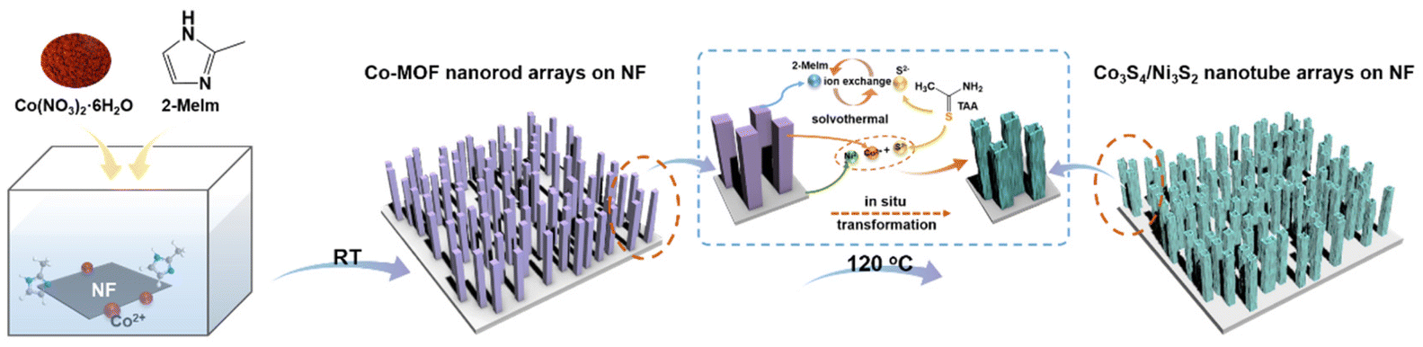
Besides the active sites of a catalyst, the geometry and configuration of a material affect the catalytic performance.25,26 To expand the number of accessible catalytic active sites, materials in the form of one-dimensional (1D) hollow thin-walled nanotubes can provide large specific surface areas that would significantly enhance mass transport and charge diffusion.27–29 Chen et al. prepared well-aligned H–Ni@Al–Co–S nanotube arrays on carbon cloth as self-standing cathodes for asymmetric supercapacitors.30 Mu et al. synthesized NiSx/Ni2P nanotube arrays on nickel foam by continuous electrodeposition that exhibited high HMF electrooxidative activity.19 However, the above studies used pre-synthesized ZnO nanorods as templates, and then removed the templates by high-temperature calcination to form nanotubes, which makes the preparation steps tedious and not amenable to large-scale production. On the other hand, metal–organic frameworks (MOFs), which are a class of hybrid crystals formed by linking metal ions and organic ligands,31 can serve as templates for preparing hollow structures with controllable morphology and tunable metal composition with fabrication methods that are relatively straightforward.32,33 Moreover, the in situ transformation of MOF nanorods into tubular metal sulfides is deemed an emerging technique for preparing anodic materials in the field of electrochemistry.34 Relying on the advantages of the structure, these metal sulfide hollow structures can provide large electrochemically active surface areas, additional electron transport pathways, and low internal resistances.35 Herein, we report on a low-temperature ethanol-assisted sulfurization method that transforms 1D Co-MOF nanorod arrays on nickel foam (NF) into Co3S4/Ni3S2 nanotube arrays via synchronous etching and ion exchange. Initially, well-aligned 1D Co-MOF nanorod arrays were fabricated on NF by traditional methods.36 Then, during solvothermal in situ sulfurization, ion exchange of Co-MOF nanorods, stripping of the Ni substrate and the generation of Co3S4 and Ni3S2 led to etching of the Co-MOF nanorods to form Co3S4/Ni3S2 nanotubes. In the presently proposed method for Co3S4/Ni3S2 nanotube arrays, NF is employed as the Ni source, which lowers the quantity of metal salts required in their preparation, and in situ sulfurization of Co-MOF nanorod arrays avoids the generation of additional metal sulfides, leading to a greener production process. The degree of vulcanization of the nanotube arrays was examined and the scope of the electrodes for electrocatalytic oxidation was assessed by using HMF, furfural, furfuryl alcohol and benzyl alcohol as typical platform chemicals.
Experimental section
Fabrication of Co-MOF nanorod arrays
Commercial nickel foam (NF) with an area of 2 × 4 cm2 was sequentially sonicated several times with 3 M HCl, ethanol, and deionized water. After that, a pre-prepared aqueous solution containing Co(NO3)2·6H2O (40 mL, 25 mM) was quickly poured into another aqueous solution of 2-MeIm (40 mL, 0.4 mM). Subsequently, a clean piece of NF was immersed in the above blue mixture solution for growing Co-MOF nanorod arrays at room temperature. Then, the obtained Co-MOF/NF slice was repeatedly washed with flowing deionized water and dried under vacuum at 60 °C.Transformation of Co-MOF nanorods into Co3S4/Ni3S2 nanotube arrays
Vertically grown Co-MOF nanorod arrays supported on NF were used as a Co-precursor providing a template for fabricating Co3S4/Ni3S2 nanotube arrays. Typically, Co-MOF nanorod arrays were placed in 60 mL of ethanol containing 0.18 g TAA and heated at 120 °C for 1 h, 3 h, or 5 h to obtain Co3S4/Ni3S2-t nanotube arrays, where t is the time in hours, and the materials are designated as Co3S4/Ni3S2-1, Co3S4/Ni3S2-3, and Co3S4/Ni3S2-5, respectively. The obtained samples were thoroughly rinsed with ethanol and dried in a vacuum at 60 °C. The original blue NF electrode turned black after the solvothermal reaction, indicating that Co-MOF had been sulfurized and transformed into the Co3S4/Ni3S2 material. The mass loadings of Co3S4/Ni3S2-1, Co3S4/Ni3S2-3, and Co3S4/Ni3S2-5 were found to be 2.3 ± 0.05 mg, 2.1 ± 0.05 mg and 2.0 ± 0.05 mg, respectively.Results and discussion
Overall, the fabrication of Co3O4/Ni3S2 nanotube arrays using nanorod Co-MOF array precursors can be divided into two steps (Fig. 1), in which Co-MOF nanorod arrays were initially grown vertically on NF substrates at ambient temperature in an aqueous solution. Co-MOF nanorod arrays on NF were sulfurized in ethanol solution, where NF was used not only as a conductive substrate, but also as a donor of Ni2+, while Co2+ was supplied by Co-MOF. During the entire reaction, large amounts of S2− are released into the solution by TAA under solvothermal conditions,37 which allows rapid exchange with the organic ligand (2-MeIm) in Co-MOF and ion–ion reactions to form metal ion (Co2+ and Ni2+) combinations (Co3S4 and Ni3S2). The in situ topotactic transformation of Co-MOF into Co3S4 most likely occurred as follows:38| CH3CSNH2 + C2H5OH → CH3(NH2)C(OC2C2H5) − SH | (1) |
| CH3(NH2)C(OC2C2H5) − SH + C2H5OH → CH3(NH2)C(OC2C2H5) + H2S | (2) |
| 4H2S + Co3(C4H5N2)8 → Co3S4 + 8C4H6H2. | (3) |
 | ||
| Fig. 1 Transformation of Co-MOF nanorod arrays on nickel foam into Co3S4-Ni3S2 nanotube arrays using ethanol with thioacetamide (TAA) under solvothermal conditions showing Ni2+ exfoliation, ion–ion reaction, ionic exchange and doping mechanisms that cause simultaneous Co-MOF nanorod decay and Co3S4-Ni3S2 nanotube growth. | ||
Ion exchange accompanied by synchronous etching brought about reassembly of the Co-MOF nanorod arrays to form hollow Co3O4/Ni3S2 nanotube arrays. The formation of hollow structures is fundamentally related to the Kirkendall effect in the ion exchange process. Due to differences in ionic radii (S2− ≫ Co2+) and diffusion coefficients, the outward diffusion of Co2+ from the Co-MOF center is greater than the inward diffusion of S2− from TAA.38,39 Therefore, the diffusion imbalance between Co2+ and S2− probably leads to the formation of Co3S4 on the surface of Co-MOF nanorods, while the continuous outward flow of Co2+ leads to the formation of core vacancies.40
Compared with the pristine Co-MOF (Fig. S1†), the Co3S4/Ni3S2-3 nanotube arrays (Fig. 2a–c) obtained after sulfurization still maintained the original nanorod array alignment, but their surfaces became rough and their structures became hollow. The TEM image further confirmed the hollow structures of Co3S4/Ni3S2-3 and the wall thickness of the nanotubes labeled by the yellow dashed line was approximately 26 nm, as shown in Fig. 2d. The sulfurization reaction time affected the structure of the resulting samples. When the solvothermal reaction time was 1 h, the nanorods gradually transformed into hollow structures, but their surfaces remained relatively smooth (Fig. S2a and S2b†). As the sulfurization time was extended to 5 h, the resulting nanotubes became rougher and even collapsed (Fig. S2c and S2d†). From the TEM images of samples prepared under different conditions (Fig. S3a and S3b†), it can also be seen that the wall thicknesses of the nanotubes gradually thinned and even broke upon increasing the sulfurization time to 5 h. An HRTEM image of the Co3S4/Ni3S2-3 material (Fig. 2e) showed clear interplanar distances of 0.29 nm and 0.17 nm that could be indexed to the (110) planes of Ni3S2 and the (440) planes of Co3S4, respectively, which suggested close contact between two crystal planes and the successful generation of a heterostructure. The Co3S4/Ni3S2-1 (Fig. S3c†) and Co3S4/Ni3S2-5 (Fig. S3d†) materials exhibited similar interface structures. TEM-EDS elemental mapping (Fig. 2f) verified that the prepared nanotubes were composed of Co, Ni, and S, which were well distributed over the entire structure. TEM-EDS demonstrated that the ratio of Ni/Co increased from 1.04 to 3.56 and the mass fraction of S increased from 11.9 wt% to 23.4 wt% in Co3S4/Ni3S2 as the sulfurization time was extended from 1 h to 5 h (Fig. S4†).
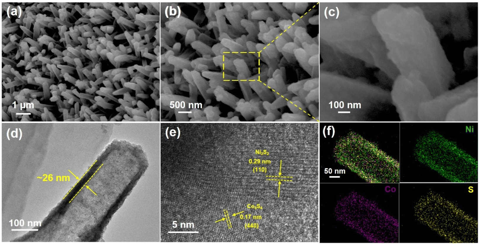 | ||
| Fig. 2 Co3S4/Ni3S2-3 nanotube arrays obtained after solvothermal sulfurization: (a–c) SEM images with different magnifications, (d) TEM image, (e) HRTEM image and (f) TEM-EDS elemental mappings. | ||
Crystal structures of the resulting electrode materials were investigated by X-ray diffraction (XRD) (Fig. S5†) and showed that patterns of the Co-MOF nanorod arrays were consistent with simulated diffraction patterns, indicating the formation of Co-MOFs. As shown in Fig. 3a, XRD patterns of Co3S4/Ni3S2-t materials for different sulfurization times matched well with the standard JCPDS cards of Co3S4 (PDF #73-1703) and Ni3S2 (PDF #44-1418), respectively, wherein diffraction peaks at 21.75°, 31.10°, 37.78°, and 49.74° could be indexed to the (101), (110), (003), and (113) crystal faces of Ni3S2, respectively, and the remaining peaks at 55.20° and 69.14° correspond to the (511) and (444) planes of Co3S4, respectively. The peak strength of sulfide was positively correlated with the sulfurization time. Diffraction peaks associated with Co-MOFs were not present in the XRD patterns of the above samples, implying the transformation of NF-supported Co-MOFs into the corresponding sulfides.
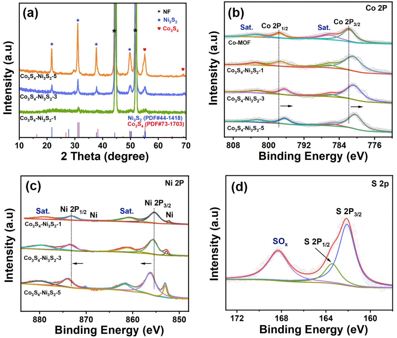 | ||
| Fig. 3 (a) XRD patterns of the as-prepared Co3S4/Ni3S2-t materials at different sulfurization times (t = 1 h, 3 h, and 5 h). (b) Co 2p XPS region, (c) Ni 2p XPS region and (d) S 2p XPS region. | ||
The valence states and chemical compositions of the as-prepared materials were characterized using X-ray photoelectron spectroscopy (XPS). As shown in Fig. S6,† the XPS survey spectrum confirmed the exclusion of nitrogen residues in the Co3S4/Ni3S2 samples. For the Co 2p spectra in Fig. 3b, two main peaks located at 781.8 eV and 797.5 eV can be indexed to Co 2p3/2 and Co 2p1/2,41 along with two corresponding satellite peaks at 786.3 eV and 803.2 eV. After solvothermal sulfurization, two distinct characteristic peaks with binding energies of 855.4 eV and 873.4 eV were observed from high-resolution Ni 2p XPS spectra to match Ni 2p3/2 and Ni 2p1/2,42 respectively (Fig. 3c). It is worth noting that with an increase in Ni3S2 content, all XPS peaks of Ni 2p in Co3S4/Ni3S2 moved towards higher binding energies, while those of Co 2p moved towards lower binding energies, indicating that the formation of an interface resulted in the existence of strong electronic interactions between Ni3S2 and Co3S4.20 The Ni3+ generated in situ through the electrochemical oxidation of Ni2+ has been shown to be the active site for the electrooxidation of HMF.43 Therefore, the red shifts of binding energies of Ni 2p in Co3S4/Ni3S2 most likely generate active Ni3+ during HMF electrooxidation that improves electrocatalytic activity.44 As shown in Fig. 3d, the high-resolution XPS spectra of S 2p exhibit peaks at 162.1 eV and 163.5 eV corresponding to S 2p3/2 and S 2p1/2, respectively, which suggests the existence of metal–sulfur bonds.45 Furthermore, the peak at 168.2 eV is indicative of surface oxidized sulfur due to exposure in air.46
The electrocatalytic performance of the as-prepared Co3S4/Ni3S2-t materials as electrodes for HMF oxidation was investigated in an H-cell at room temperature with 1 mol L−1 KOH as the electrolyte. As shown in Fig. 4a, the HMF oxidation onset potentials of the samples were roughly the same (ca. 1.3 V vs. RHE), after which the current density increased rapidly, with that for Co3S4/Ni3S2-3 rising the fastest. When the sulfurization time of the prepared material was prolonged from 1 h to 3 h as shown for Co3S4/Ni3S2-1 and Co3S4/Ni3S2-3 (Fig. 4a), the current density remarkably increased, inferring that sulfurization time was important for promoting synergistic interactions between the Co3S4 and Ni3S2 interfaces, thereby improving charge transfer. As the sulfurization time of the materials was extended to 5 h (Co3S4/Ni3S2-5, Fig. 4a), the driving potential at the same current density became higher, which can be largely attributed to the attrition and collapse of the nanotube structures caused by the solvothermal sulfurization conditions. Fig. 4b shows the HMF oxidation potentials of different Co3S4/Ni3S2-t electrodes at the same current density (10, 50, and 100 mA cm−2), further demonstrating the advantages of the Co3S4/Ni3S2-3 electrode. The intrinsic activity of different samples in the presence of HMF was assessed by the Tafel plot (Fig. 4c). Co3S4/Ni3S2-3 exhibited the lowest Tafel slope (71.8 mV dec−1) compared with Co3S4/Ni3S2-1 (108.4 mV dec−1) and Co3S4/Ni3S2-5 (114.0 mV dec−1), demonstrating its favorable HMF electrooxidation kinetics. Since the OER is the main competitive reaction in HMF oxidation, LSV analyses of the Co3S4/Ni3S2-3 electrodes were performed in 1 M KOH with and without 10 mM HMF. As shown in Fig. 4d, in the presence of a 10 mM HMF solution, the onset potential of the Co3S4/Ni3S2-3 electrode shifted negatively to 1.31 V vs. RHE compared with the OER (1.54 V vs. RHE), showing that HMF oxidation was more favorable than the OER over Co3S4/Ni3S2-3, which can also be seen by the smaller Tafel slope of HMF electrooxidation compared with the OER (Fig. 4d inset). Co3S4/Ni3S2-1 and Co3S4/Ni3S2-5 exhibited similar tendencies (Fig. S7a and b†) to those shown in Fig. 4d. However, the Co-MOF nanorod electrode did not have significant catalytic activity for HMF oxidation (Fig. S7c†), which means that the catalytic performance of HMF was affected by the composition and structure of the electrode. Bare NF electrodes are able to oxidize HMF, but their relatively poor catalytic activity is insufficient to interfere with the Co3S4/Ni3S2-t catalytic materials on NF (Fig. S8†).
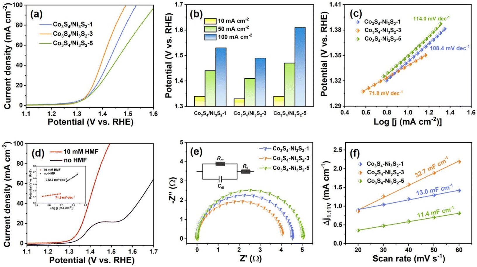 | ||
| Fig. 4 Properties and characteristics of Co3S4/Ni3S2-t materials: (a) LSV curves of Co3S4/Ni3S2-1, Co3S4/Ni3S2-3 and Co3S4/Ni3S2-5 in 1 M KOH with 10 mM HMF. (b) HMF oxidation potentials at different current densities; (c) Tafel plots of Co3S4/Ni3S2-1, Co3S4/Ni3S2-3 and Co3S4/Ni3S2-5 in 1 M KOH with 10 mM HMF; (d) LSV curves of Co3S4/Ni3S2-3 in 1 M KOH with and without 10 mM HMF (inset, corresponding Tafel plots); (e) Nyquist plots of Co3S4/Ni3S2-1, Co3S4/Ni3S2-3 and Co3S4/Ni3S2-5 in 1 M KOH with 50 mM HMF; and (f) capacitive currents of Co3S4/Ni3S2-1, Co3S4/Ni3S2-3 and Co3S4/Ni3S2-5 in 1 M KOH. | ||
Electrochemical impedance spectroscopy (EIS) was conducted to analyze the kinetics of Co3S4/Ni3S2-1, Co3S4/Ni3S2-3 and Co3S4/Ni3S2-5 materials for promoting HMF electrooxidation. Nyquist plots were fitted with an equivalent circuit model (Fig. 4e, inset) and the fitted values for each component were calculated (Table S1†). As displayed in Fig. 4e, Co3S4/Ni3S2-3 (4.08 Ω) had a relatively small charge transfer resistance (Rct) compared with Co3S4/Ni3S2-1 (4.53 Ω) and Co3S4/Ni3S2-5 (5.04 Ω), demonstrating its faster electron transfer at the electrode/electrolyte interface than other materials. In addition, the Nyquist plot of Co3S4/Ni3S2-3 observed for 1 M KOH without HMF was an arc with a large inner diameter (Fig. S9†), which indicated that the Rct of OER was much higher than that of HMF oxidation. The electrochemically active surface area (ECSA) is usually determined using the double-layer capacitance (Cdl), which is calculated by recording CV curves at different scan rates in the non-faradaic region (Fig. S10†). As evident from Fig. 4f, Co3S4/Ni3S2-3 had a Cdl value of 32.7 mF cm−2, while those for Co3S4/Ni3S2-1 and Co3S4/Ni3S2-5 were 13.0 mF cm−2 and 11.4 mF cm−2, respectively, which is important since the ECSA is proportional to Cdl. Consequently, the ECSA of Co3S4/Ni3S2-3 was 2.5 times and 2.9 times those of Co3S4/Ni3S2-1 and Co3S4/Ni3S2-5, respectively, illustrating that the unique hollow tubular nanostructures of Co3S4/Ni3S2-3 provided more active sites for electrocatalytic reactions than other electrode materials. In addition, the EIS (Fig. S11†) and Cdl (Fig. S12†) of the Co-MOF were examined. Compared with Co3S4/Ni3S2 nanotubes, the larger EIS (12.19 Ω) and smaller Cdl (9.6 mF cm−2) of Co-MOF nanorods further verified that the conversion of nanorods to nanotubes greatly improved the electrocatalytic oxidation performance for HMF.
The electrochemical conversion of HMF to FDCA with the Co3S4/Ni3S2-3 electrode was first studied by linear sweep voltammetry (Fig. S13†), where it was found that there was an uptrend in the LSV curve for 10 mM HMF that gradually decreased in slope when the potential exceeded 1.5 V vs. RHE; after the potential exceeded 1.6 V vs. RHE, the slope increased, which can be explained by the occurrence of the OER. In contrast, the LSV curve for 50 mM HMF maintained a relatively stable upward trend implying that low concentrations of HMF were more prone to OER competitive reactions at a high potential. Taking 10 mM HMF as an example (Fig. 5a and Fig. S14†), the yield and FE of FDCA at different applied potentials and time required after passing 116 C charges (theoretical value for complete conversion of HMF) were plotted. As the applied potential gradually increased (1.35, 1.4, 1.45, 1.5, 1.6, and 1.7 V) vs. RHE (Fig. 5a), the HMF electrolysis time gradually declined (150, 51, 21, 15, 12, and 11 min) and the yields and FE values of FDCA first increased and then decreased and were close to 100% at 1.40 V and 1.45 V vs. RHE, but overall remained at 80%. Excessively long reaction times (150 min) at low potentials (1.35 V vs. RHE) may lead to the formation of a small amount of humins,47 so appropriately increasing the potential to shorten the reaction time is beneficial for the overall conversion of HMF. When the applied potential exceeded 1.5 V vs. RHE (Fig. 5a), the yield and FE of FDCA decreased slightly due to the occurrence of OER competitive reactions. However, when the applied potential reached 1.8 V vs. RHE (Fig. 5a), the yield and FE of FDCA dropped sharply and violent bubbles were observed at the cathode, which can be attributed to the uncontrollable water splitting reaction in the system. The results in Fig. 5a reveal that the as-prepared Co3S4/Ni3S2-3 electrode had a wide range of applied potentials (1.35–1.70) V vs. RHE that can be used for electrochemical oxidation of HMF, as well as the rapid acquisition of FDCA under high potential.
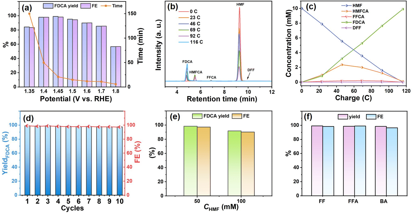 | ||
| Fig. 5 Performance of Co3S4/Ni3S2 as the catalytic electrode: (a) FDCA yield, FE and time required of Co3S4/Ni3S2 at different potentials in 1 M KOH with 10 mM HMF; (b) HPLC traces of HMF electrolysis in 1 M KOH with 10 mM HMF at 1.43 V vs. RHE; (c) concentration of HMF and its oxidation products during HMF electrolysis as they vary with passing charge; (d) HMF electrolysis using Co3S4/Ni3S2 for ten successive cycles in 1 M KOH with 10 mM HMF at 1.43 V vs. RHE; (e) FDCA yield and FE of Co3S4/Ni3S2 for HMF electrooxidation for 50 mM HMF and 100 mM HMF at 1.43 V vs. RHE; (f) yield and FE of oxidation products of furfural (FF), furfuryl alcohol (FFA) and benzyl alcohol (BA) at 1.43 V vs. RHE. | ||
Subsequent electrocatalytic experiments were carried out at 1.43 V vs. RHE applied potential using Co3S4/Ni3S2-3 as the anode unless otherwise specified. Generally, there are two pathways for HMF electrooxidation; one is the 5-hydroxymethyl-2-furanformic acid (HMFCA) pathway via aldehyde oxidation, and the other is the 2,5-diformylfuran (DFF) pathway via alcohol oxidation (Fig. S15†). As shown in Fig. 5b and c, HMF in the electrolyte was gradually oxidized and converted into FDCA with an increase of charge on Co3S4/Ni3S2. In this process, only two intermediates, HMFCA and FFCA, were observed by HPLC, demonstrating that HMF electrooxidation with the Co3S4/Ni3S2 electrode followed the aldehyde oxidation pathway. In the recycling experiments of the Co3S4/Ni3S2 electrode, the yields and FE values of FDCA were found to be above 97.5% after ten cycles with the same Co3S4/Ni3S2 electrode, suggesting that the electrode had good stability for HMF electrolysis (Fig. 5d). Considering the product streams formed, separation of FDCA can be achieved through precipitation by lowering the solution pH to values less than 2 or 3 and membrane filtration of the solution.48 The performance of the electrode materials developed in this work and those reported in the literature for HMF electrooxidation is shown in Table S2.† The Co3S4/Ni3S2 electrode exhibited essentially 100% FDCA yields at 100% FE at low HMF concentrations (10 mM) and compared well with the highest performing electrodes (e.g. CoO-CoSe215 in Table S2†), exhibiting greater than 90% FDCA yields and FE values for high concentrations of HMF (50 mM and 100 mM) (Table S2† and Fig. 5e), illustrating that the as-prepared Co3S4/Ni3S2 catalytic electrode had high activity and could effectively inhibit the decomposition of HMF in the alkaline electrolyte.
Other biomass-related substrates (FF, FFA and BA) were studied to examine the scope of the Co3S4/Ni3S2 electrode (Fig. S16†) wherein after adding 10 mM of different organic molecules, the oxidation onset potential shifted to a lower potential than that of the OER, indicating a favorable oxidation reaction. Thus, biomass-related substrates could be treated at 1.43 V vs. RHE constant potential and were almost completely converted into the corresponding high value-added acid products (FA, FA and benzoic acid, respectively) after passing theoretical charge amounts (Fig. 5f). The high selectivity (>98%) and FE (>96%) for the electrooxidation of FF, FFA and BA confirmed the versatility of the Co3S4/Ni3S2 electrodes (detailed data are given in Table S3†).
The used Co3S4/Ni3S2 electrode was characterized in detail, and no apparent changes were observed in its crystal structure (Fig. S17a†). Furthermore, the used Co3S4/Ni3S2 electrode maintained the initial 1D hollow structure well (Fig. S17b and c†), which further demonstrated the existence of Ni, Co and S elements in the sample (Fig. S17d†) and confirmed the durability of the electrode. Subsequently, XPS analyses were carried out to determine the evolution of the chemical states of Co3S4/Ni3S2 before and after the reaction (Fig. S18†). As shown in Fig. S18a and S18b,† distinct negative shifts in the binding energies of Ni 2p and Co 2p were observed during HMF electrooxidation, indicating a significant increase in electron density in the Co3S4/Ni3S2 used, which may be related to the formation of oxyhydroxide (Ni/CoOOH).49 The XPS spectra of O 1s (Fig. S18c†) of the electrode before and after use showed peak enhancement of the –OH species, further supporting the formation of hydroxyoxide.14,50 A negative shift of the O 1s peak occurred after continuous electrolysis of HMF, indicating that hydroxyoxide formation on the surface of the electrode was probably caused by electron accumulation of O species.51 For S2p, all XPS peaks became weakened after electrolysis, demonstrating dissolution into the electrolyte during the reaction (Fig. S18d†).37 The above results imply that Ni/CoOOH formed on the surface of Ni3S2/Co3S4 and may be the true active species in HMF electrooxidation.
Conclusions
In summary, Co3S4/Ni3S2 nanotube arrays with hollow structures were synthesized by low-temperature (ca. 120 °C) in situ sulfurization that promoted ion exchange and synchronous etching 1D Co-MOF nanorod arrays to form nanotube arrays. The Ni3S2/Co3S4 nanotube arrays were assessed as anode electrodes for electrocatalytic oxidation reactions. The unique tubular structure of the Ni3S2/Co3S4 nanotubes provided abundant active sites and favorable charge transport paths that resulted in superior electrocatalytic performance for the oxidation of HMF and biomass-related compounds (furfural, furfuryl alcohol, and benzyl alcohol). The Ni3S2/Co3S4 nanotube array electrode has a wide potential range from 1.35 to 1.7 V vs. RHE in its application to HMF oxidation and is able to handle high (100 mM HMF) substrate concentrations. The Ni3S2/Co3S4 nanotube array electrode is simple to prepare and exhibits good stability, both of which are important for industrial applications. The as-prepared Ni3S2/Co3S4 nanotube arrays have a wide scope as electrodes for electrooxidation of biomass-related substrates into their corresponding acid products in high yields and with high faradaic efficiencies.Conflicts of interest
There are no conflicts to declare.Acknowledgements
The authors appreciate the financial support from the National Natural Science Foundation of China (No. 22178181), the Natural Science Foundation of Tianjin (No. 21JCZDJC00180), the Fundamental Research Funds for the Central Universities (Nankai University (No. 63231085)) and the Tianjin Research Innovation Project for Postgraduate students (No. 2021YJSB045).References
- M. Sajid, X. Zhao and D. Liu, Green Chem., 2018, 20, 5427–5453 RSC.
- D. A. Giannakoudalds, J. C. Colmenares, D. Tsiplakides and K. S. Triantafyllidis, ACS Sustainable Chem. Eng., 2021, 9, 1970–1993 CrossRef.
- P. Prabhu, Y. Wan and J.-M. Lee, Matter, 2020, 3, 1162–1177 CrossRef.
- C. Xu, E. Paone, D. Rodriguez-Padron, R. Luque and F. Mauriello, Chem. Soc. Rev., 2020, 49, 4273–4306 RSC.
- B. You, X. Liu, N. Jiang and Y. J. Sun, J. Am. Chem. Soc., 2016, 138, 13639–13646 CrossRef CAS PubMed.
- B. You, X. Liu, X. Liu and Y. J. Sun, ACS Catal., 2017, 7, 4564–4570 CrossRef CAS.
- D. Zheng, J. Li, S. Ci, P. Cai, Y. Ding, M. Zhang and Z. Wen, Appl. Catal., B, 2020, 277, 119178 CrossRef CAS.
- P. L. Zhang, X. Sheng, X. Y. Chen, Z. Y. Fang, J. Jiang, M. Wang, F. S. Li, L. Z. Fan, Y. S. Ren, B. B. Zhang, B. J. J. Timmer, M. S. G. Ahlquist and L. C. Sun, Angew. Chem., Int. Ed., 2019, 58, 9155–9159 CrossRef CAS PubMed.
- Y. Meng, S. Yang and H. Li, ChemSusChem, 2022, 15, e202102581 CrossRef CAS PubMed.
- R. A. Sheldon, Green Chem., 2014, 16, 950–963 RSC.
- P. Pal and S. Saravanamurugan, ChemSusChem, 2019, 12, 145–163 CrossRef CAS PubMed.
- J. Wang, X. Zhang, G. Wang, Y. Zhang and H. Zhang, Chem. Commun., 2020, 56, 13611–13614 RSC.
- C. Yang, C. Wang, L. Zhou, W. Duan, Y. Song, F. Zhang, Y. Zhen, J. Zhang, W. Bao, Y. Lu, D. Wang and F. Fu, Chem. Eng. J., 2021, 422, 130125 CrossRef CAS.
- L. Gao, Z. Liu, J. Ma, L. Zhong, Z. Song, J. Xu, S. Gan, D. Han and L. Niu, Appl. Catal., B, 2020, 261, 118235 CrossRef.
- X. Huang, J. L. Song, M. L. Hua, Z. B. Xie, S. S. Liu, T. B. Wu, G. Y. Yang and B. X. Han, Green Chem., 2020, 22, 843–849 RSC.
- N. Jiang, B. You, R. Boonstra, I. M. T. Rodriguez and Y. Sun, ACS Energy Lett., 2016, 1, 386–390 CrossRef CAS.
- W.-J. Liu, L. Dang, Z. Xu, H.-Q. Yu, S. Jin and G. W. Huber, ACS Catal., 2018, 8, 5533–5541 CrossRef CAS.
- X. J. Bai, W. X. He, X. Y. Lu, Y. Fu and W. Qi, J. Mater. Chem. A, 2021, 9, 14270–14275 RSC.
- B. Zhang, H. Fu and T. Mu, Green Chem., 2022, 24, 877–884 RSC.
- Y. B. Zhang, Z. M. Xue, X. H. Zhao, B. L. Zhang and T. C. Mu, Green Chem., 2022, 24, 1721–1731 RSC.
- W. Zhu, Z. Yue, W. Zhang, N. Hu, Z. Luo, M. Ren, Z. Xu, Z. Wei, Y. Suo and J. Wang, J. Mater. Chem. A, 2018, 6, 4346–4353 RSC.
- X. Luo, P. Ji, P. Wang, R. Cheng, D. Chen, C. Lin, J. Zhang, J. He, Z. Shi, N. Li, S. Xiao and S. Mu, Adv. Energy Mater., 2020, 10, 1903891 CrossRef CAS.
- Z. Li, M. Hu, P. Wang, J. Liu, J. Yao and C. Li, Coord. Chem. Rev., 2021, 439, 213953 CrossRef CAS.
- Z. Kou, T. Wang, Q. Gu, M. Xiong, L. Zheng, X. Li, Z. Pan, H. Chen, F. Verpoort, A. K. Cheetham, S. Mu and J. Wang, Adv. Energy Mater., 2019, 9, 1803768 CrossRef.
- Y. Feng, K. Yang, R. L. L. Smith Jr. and X. Qi, J. Mater. Chem. A, 2023, 11, 6375–6383 RSC.
- G. Solomon, A. Landstrom, R. Mazzaro, M. Jugovac, P. Moras, E. Cattaruzza, V. Morandi, I. Concina and A. Vomiero, Adv. Energy Mater., 2021, 11, 2101324 CrossRef CAS.
- X. Yu, W. Zhang, L. She, Y. Zhu, Y. Fautrelle, Z. Ren, G. Cao, X. Lu and X. Li, Chem. Eng. J., 2022, 430, 133073 CrossRef CAS.
- J. Xiao, L. Wan, S. Yang, F. Xiao and S. Wang, Nano Lett., 2014, 14, 831–838 CrossRef CAS PubMed.
- Y. Wang, H. L. Wei, H. F. Lv, Z. X. Chen, J. J. Zhang, X. Y. Yan, L. Lee, Z. M. M. Wang and Y. L. Chueh, ACS Nano, 2019, 13, 11235–11248 CrossRef CAS PubMed.
- J. Huang, J. Wei, Y. Xiao, Y. Xu, Y. Xiao, Y. Wang, L. Tan, K. Yuan and Y. Chen, ACS Nano, 2018, 12, 3030–3041 CrossRef CAS PubMed.
- H. Furukawa, K. E. Cordova, M. O’Keeffe and O. M. Yaghi, Science, 2013, 341, 1230444 CrossRef PubMed.
- S. S. A. Shah, T. Najam, M. K. Aslam, M. Ashfaq, M. M. Rahman, K. Wang, P. Tsiakaras, S. Q. Song and Y. Wang, Appl. Catal., B, 2020, 268, 18570–18570 CrossRef.
- T. Yan, Y. Feng, X. Ren, J. Li, Y. Lu, M. Sun, L. Yan, Q. Wei and H. Ju, J. Materiomics, 2021, 7, 721–727 CrossRef.
- W. Lu, J. Shen, P. Zhang, Y. Zhong, Y. Hu and X. W. D. Lou, Angew. Chem., Int. Ed., 2019, 58, 15441–15447 CrossRef CAS PubMed.
- G. Nagaraju, S. C. Sekhar, B. Ramulu and J. S. Yu, Energy Storage Mater., 2021, 35, 750–760 CrossRef.
- Y. Ma, J. He, Z. Kou, A. M. Elshahawy, Y. Hu, C. Guan, X. Li and J. Wang, Adv. Mater. Interfaces, 2018, 5, 1800222 CrossRef.
- H. Su, S. Song, S. Li, Y. Gao, L. Ge, W. Song, T. Ma and J. Liu, Appl. Catal., B, 2021, 293, 120225 CrossRef CAS.
- Z.-F. Huang, J. Song, K. Li, M. Tahir, Y.-T. Wang, L. Pan, L. Wang, X. Zhang and J.-J. Zou, J. Am. Chem. Soc., 2016, 138, 1359–1365 CrossRef CAS PubMed.
- Y. D. Yin, R. M. Rioux, C. K. Erdonmez, S. Hughes, G. A. Somorjai and A. P. Alivisatos, Science, 2004, 304, 711–714 CrossRef CAS PubMed.
- M. Kim, H. Seok, N. C. S. Selvam, J. Cho, G. H. Choi, M. G. Nam, S. Kang, T. Kim and P. J. Yoo, J. Power Sources, 2021, 493, 229688 CrossRef CAS.
- K. Ge, S. Sun, Y. Zhao, K. Yang, S. Wang, Z. Zhang, J. Cao, Y. Yang, Y. Zhang, M. Pan and L. Zhu, Angew. Chem., Int. Ed., 2021, 60, 12097–12102 CrossRef CAS PubMed.
- H. Xu, Y. Liao, Z. Gao, Y. Qing, Y. Wu and L. Xia, J. Mater. Chem. A, 2021, 9, 3418–3426 RSC.
- L. F. Gao, Y. Bao, S. Y. Gan, Z. H. Sun, Z. Q. Song, D. X. Han, F. H. Li and L. Niu, ChemSusChem, 2018, 11, 2547–2553 CrossRef CAS PubMed.
- S. Yang, Y. Guo, Y. Zhao, L. Zhang, H. Shen, J. Wang, J. Li, C. Wu, W. Wang, Y. Cao, S. Zhuo, Q. Zhang and H. Zhang, Small, 2022, 18, 2201306 CrossRef CAS PubMed.
- J.-c. Zheng, Y.-y. Yao, G.-q. Mao, H.-z. Chen, H. Li, L. Cao, X. Ou, W.-j. Yu, Z.-y. Ding and H. Tong, J. Mater. Chem. A, 2019, 7, 16479–16487 RSC.
- X. Liang, B. Zheng, L. Chen, J. Zhang, Z. Zhuang and B. Chen, ACS Appl. Mater. Interfaces, 2017, 9, 23222–23229 CrossRef CAS PubMed.
- Z. Zhou, C. Chen, M. Gao, B. Xia and J. Zhang, Green Chem., 2019, 21, 6699–6706 RSC.
- S. R. Kubota and K. S. Choi, ChemSusChem, 2018, 11, 2138–2145 CrossRef CAS PubMed.
- A. Sivanantham, P. Ganesan and S. Shanmugam, Adv. Funct. Mater., 2016, 26, 4661–4672 CrossRef CAS.
- X. Li, G.-Q. Han, Y.-R. Liu, B. Dong, W.-H. Hu, X. Shang, Y.-M. Chai and C.-G. Liu, ACS Appl. Mater. Interfaces, 2016, 8, 20057–20066 CrossRef CAS PubMed.
- H. L. Wang, C. Li, J. T. An, Y. Zhuang and S. Y. Tao, J. Mater. Chem. A, 2021, 9, 18421–18430 RSC.
Footnote |
| † Electronic supplementary information (ESI) available. See DOI: https://doi.org/10.1039/d3gc03151a |
| This journal is © The Royal Society of Chemistry 2023 |