
High efficiency coupled electrocatalytic CO2 reduction to C2H4 with 5-hydroxymethylfurfural oxidation over Cu-based nanoflower electrocatalysts†
Zonghang
Zhang
 a,
Shan
Liu
a,
Zhao
Wu
*b,
Xiaoyan
Chen
a,
Jingui
Wang
a,
Yuji
Gao
a,
Shuai
Wang
a,
Furong
Tao
a and
Guangqiang
Lv
*a
a,
Shan
Liu
a,
Zhao
Wu
*b,
Xiaoyan
Chen
a,
Jingui
Wang
a,
Yuji
Gao
a,
Shuai
Wang
a,
Furong
Tao
a and
Guangqiang
Lv
*a
aShandong Provincial Key Laboratory of Molecular Engineering, Qilu University of Technology (Shandong Academy of Sciences), Jinan 250353, Shandong, China. E-mail: lvguangqiang@qlu.edu.cn
bSafety and environmental protection department of Sinopec Jinan Company, Jinan, Shandong 250101, China. E-mail: wuzhao.jnlh@sinopec.com
First published on 21st June 2023
Abstract
To improve the total value of the redox products and energy conversion efficiency in CO2 electroreduction (CO2RR) and 5-hydroxymethylfurfural electrooxidation (HMFOR), commercial Cu foam was chemically oxidized into nanoflower CuO on its surface and used as an electrocatalyst in both CO2RR and HMFOR. In CO2RR, the prepared CuO nanoflower on Cu foam (CuO-NF@Cu) was quickly reduced to hybrid Cu2O/Cu nanoflower (Cu2O/Cu-NF@Cu). At a reduction potential of −0.95 V (vs. RHE), a high C2H4 faradaic efficiency (FE) up to 70% with a current density of 104.5 mA cm−2 can be obtained within 45 h of testing. In HMFOR, CuO-NF@Cu gave a 99.3% FDCA FE at a potential of 1.62 V (vs. RHE). Moreover, CO2RR and HMFOR can be coupled together with CuO-NF@Cu as the anode electrocatalyst and Cu2O/Cu-NF@GDL as the cathode electrocatalyst. A current density up to 188.8 mA cm−2 at a cell voltage of 2.75 V can be obtained. FEs of FDCA and C2H4 up to 96.6%/74.5%, respectively, were achieved in coupled CO2RR-HMFOR within 5 h. This work makes it easy to simultaneously efficiently convert CO2 to high-value C2H4 and upgrade a renewable biomass platform compound.
Introduction
The rapid development of industry over the past hundred years has led to the large-scale use of nonrenewable fossil resources, causing a substantial increase in the CO2 concentration in the atmosphere.1–4 Developing and utilizing renewable energy and resources, such as solar, wind, electric, and biomass resources, and selectively reducing CO2 generated by fossil resources to valuable fuels or chemicals with clean and renewable energy is significant for future development.5–7 The selective reduction of CO2 (CO2RR) into one specific multi-carbon product with high Faraday efficiency (FE) over one easily prepared electrocatalyst is far from practical application owing to the uncertain and kinetically sluggish C–C coupling and H addition.8–12 Moreover, a sluggish oxygen evolution reaction (OER) at the anode results in high anodic potential and as high as 94.5% of the input energy is consumed at the anode with low-value O2 produced.13–15 Thus, substituting OER with reactions of lower energy requirements and value-added oxidative products would significantly reduce the anodic potentials, as well as raise the efficiency for CO2RR.16–185-Hydroxymethylfurfural (HMF) is an important biomass-derived platform molecule. It can be oxidized into 2,5-furandicarboxylic acid (FDCA) under certain conditions.19 FDCA has a similar molecular structure to terephthalic acid and can be used as an alternative chemical in the fields of fine chemicals and medicines.20 Traditionally, the production of FDCA from HMF needs harsh reaction conditions, such as a high reaction temperature, high oxygen pressure and noble metal catalysts.21,22 Electrocatalysis of HMF (HMFOR) can be conducted under mild conditions without high reaction temperature, high oxygen pressure, or an expensive catalyst.23 However, the reported electrocatalysts for HMF oxidation are prepared with complicated procedures or give low FDCA selectivity.24–26 On the other hand, the kinetics of the synergistic hydrogen evolution reaction (HER) at the cathode is not ideal and restricts the anode HMF oxidation. Thus, coupling CO2RR and HMFOR seems an attractive approach to solving the above problem in CO2RR and HMFOR. In this field, researchers have tried coupling CO2RR (to formic acid, or CO) with HMFOR (to FDCA, maleic acid, formic acid),18,27,28 CO2RR (to CO or formate) with CH3OH oxidation (to formate),5,29 HMFOR (to FDCA) with 4-nitrophenol hydrogenation,30etc. Generally, only a C1 product was achieved in the CO2RR coupled reaction and there was low FDCA selectivity in the HMFOR coupled reaction with low current density and complicated, different electrocatalyst preparation procedures in the anode and cathode.31 Therefore, an easily prepared electrocatalyst that can simultaneously give high FDCA selectivity in anode HMF oxidation and high FE in cathode CO2RR to produce high-value C2 products is very important for the utilization of renewable biomass resources, renewable electric energy, and cyclic utilization of CO2 resources.
In the past decades, Au, Pt, Pd, Ru or their alloys have been widely studied as anode electrocatalysts in HMFOR.32–34 Recently, studies on transition metal (Fe, Co, Ni, Cu, etc.) – based electrocatalysts have caused rapid development in HMFOR and even higher target product selectivity and energy efficiency have been obtained.35–39 In general, researchers concluded that the active phases in HMF electrooxidation with transition metal catalysts should be their nitride or oxide compounds with unique nanostructures. The atomic vacancies and local structural disorder created by exotic species like oxygen,37,40 nitride,38 sulphur,39,41 phosphorus,36 and selenium,42 the morphology of the nanostructure, and the valence states of the metal sites are responsible for their activity in HMFOR. In CO2RR, a copper-based catalyst was shown to be an efficient electrocatalyst toward C2+ products.43–46 Defect sites with low-coordinated Cu atoms and polarized Cuδ+ (0 < δ ≤ 1) were deemed responsible for promoting the C–C coupling step at low overpotentials in CO2RR.44 This feature indicates that one elaborately prepared oxide-derived Cu catalyst may be suitable in both CO2RR and HMFOR as follows.
| HMF + 6OH− → FDCA + 4H2O + 6e− (Anode reaction) |
| 2CO2 + 12H+ + 12e− → C2H4 + 4H2O (Cathode reaction) |
| 2CO2 + 2HMF + 12H2O → C2H4 + 2FDCA (Overall reaction) |
Here, a simply prepared CuO nanoflower (CuO-NF) sheet over a Cu foam surface (CuO-NF@Cu) was prepared and used as the electrocatalyst in CO2RR and HMFOR. In CO2RR, the CuO-NF in the resultant CuO-NF@Cu quickly converted into the Cu2O phase in CO2RR and formed a stable Cu+/Cu interface. The obtained Cu2O/Cu-NF@Cu exhibited facilitated kinetics of CO2RR into C2H4, leading to a high C2H4 FE of ca. 70% at −0.95 V (vs. RHE), along with a current density of 104.5 mA cm−2 within the tested 45 h. On the other side, CuO-NF@Cu can give 100% HMF conversion with a 99.6% FDCA yield and 99.3% FDCA FE at a potential of 1.62 V (vs. RHE) in 45 min. Moreover, CO2RR and HMFOR can be coupled together in an integrated flowing cell with CuO-NF@Cu as the electrocatalyst in both the anode and cathode (Fig. 1). A stable current density up to 188.8 mA cm−2 at a cell voltage of 2.75 V can be obtained, along with a FDCA FE up to 96.6% and a C2H4 FE up to 74.5%. The excellent performance of the Cu-based nanoflower electrocatalyst demonstrates great promise for the large scale cyclic utilization of CO2 resources generated from coal or oil and biomass valorization, facilitated by renewable electric energy from wind, solar, etc.
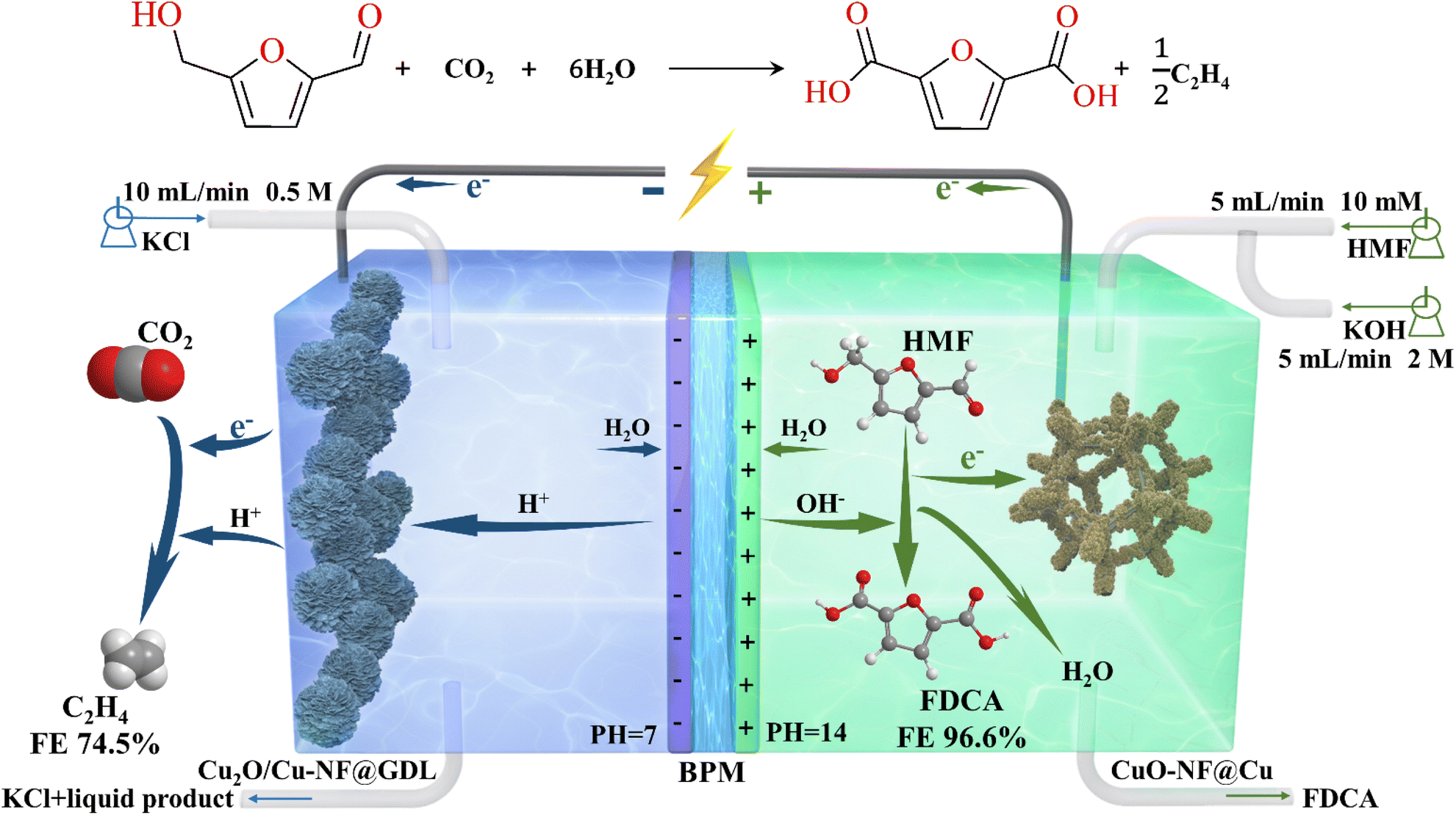 | ||
| Fig. 1 Schematic illustration of integrated electrolysis flow cell coupling CO2RR with HMFOR. | ||
Results and discussion
Catalyst preparation and characterization
In this study, Cu nanoflower sheet catalysts were grown over foam Cu. Detailed catalyst preparation methods are given in the ESI† and are illustrated in Fig. S1 (in the ESI†). The morphology and microstructure of the catalyst in different stages in Fig. S1† are characterized by SEM and shown in Fig. S2.† Without stirring, the yellow surface of the pristine Cu foam turned blue in 10 min, indicating the formation of Cu(OH)2 over the Cu foam. The SEM images in Fig. S2a and b† show that the surface of the Cu foam turned from smooth to rough and Cu(OH)2 nanorods uniformly covered the surface of the Cu foam (Cu(OH)2-NR@Cu). After 20 min, the surface turned dark blue, indicating that partial Cu(OH)2 had dehydrated to CuO. The SEM images showed that CuO nucleated and formed a small amount of CuO nanoflowers over the Cu(OH)2 nanorods (CuO/Cu(OH)2-NR@Cu, Fig. S2c†). Vigorous stirring in the catalyst preparation can accelerate this transformation and a black surface can be found in 20 min with stirring in the catalyst preparation, implying that a majority of the Cu foam surface is covered by CuO. The SEM image in Fig. S2d† shows that CuO nanoflowers covered the whole surface of the Cu foam (CuO-NF@Cu). Under alkaline conditions, the inorganic polymerization reactions of Cu(OH)2, CuO/Cu(OH)2, and CuO are as follows.| Cu + 4OH− + (NH4)2S2O8 → Cu(OH)2 + 2NH3(g) + 2SO42− + 2H2O | (1) |
Cu(OH)2 ![[left over right harpoons]](https://www.rsc.org/images/entities/char_21cb.gif) CuO + H2O CuO + H2O | (2) |
At first, Cu atoms on the Cu foam surface dissolved into Cu2+ in the presence of (NH4)2S2O8. In the presence of OH−, partial Cu2+ formed Cu(OH)2 and deposited on the Cu foam surface (Cu(OH)2@Cu, Fig. S2b†). With the reaction time prolonged to 20 min and Cu2+ saturated in the solution, Cu(OH)2 dehydrated to CuO, which is thermodynamically favorable. The formed CuO nucleated and grew on the surface with the production and dehydration of Cu(OH)2. Depending on the rates of formation and dehydration of Cu(OH)2, a mixture of CuO and Cu(OH)2 can exist on the surface (CuO/Cu(OH)2@Cu, Fig. S2c†). Stirring during the reaction accelerated the nucleation rate until the surface oxygen content no longer increased, indicating that the surface was completely covered by the oxide layer (Fig. S2d†). Finally, vertically arranged and densely stacked CuO nanoflowers (CuO-NF@Cu) were synthesized. This method not only prevents the increase of contact resistance between the nanorods/flowers and the conductive substrate but also interferes with the diffusion of the electrolyte, thereby improving the catalytic performance.
Further SEM observations and analysis of the CuO-NF@Cu were conducted and are shown in Fig. 2. An EDS elemental analysis of the nanoflowers and the EDS elemental spectra showed that the Cu and O elements are evenly distributed on the nanoflowers, with an atomic ratio of oxygen to copper close to 1![[thin space (1/6-em)]](https://www.rsc.org/images/entities/char_2009.gif) :1, indicating the successful preparation of CuO-NF@Cu (Fig. 2b and c). Meanwhile, an EDS elemental analysis of the nanoflowers on CuO/Cu(OH)2@Cu showed that the atomic ratio of oxygen to copper was also close to 1:1 (Fig. S3†), confirming that CuO nanoflowers nucleated and grew on the Cu(OH)2 nanorods. High-magnification SEM and HRTEM in Fig. 3a and b indicate that the CuO nanoflowers are composed of ultra-thin CuO nanosheets, with an average width of ca. 200 nm. The thickness of the nanosheets was measured with atomic force microscopy (AFM) and found to be ca. 4.5 nm (Fig. 3c). The ultra-thin nanosheets of CuO-NF@Cu provide more catalytic active sites during the electrocatalytic process. The above characterization demonstrated the successive preparation of CuO nanoflowers with nanosheets over Cu foam.
:1, indicating the successful preparation of CuO-NF@Cu (Fig. 2b and c). Meanwhile, an EDS elemental analysis of the nanoflowers on CuO/Cu(OH)2@Cu showed that the atomic ratio of oxygen to copper was also close to 1:1 (Fig. S3†), confirming that CuO nanoflowers nucleated and grew on the Cu(OH)2 nanorods. High-magnification SEM and HRTEM in Fig. 3a and b indicate that the CuO nanoflowers are composed of ultra-thin CuO nanosheets, with an average width of ca. 200 nm. The thickness of the nanosheets was measured with atomic force microscopy (AFM) and found to be ca. 4.5 nm (Fig. 3c). The ultra-thin nanosheets of CuO-NF@Cu provide more catalytic active sites during the electrocatalytic process. The above characterization demonstrated the successive preparation of CuO nanoflowers with nanosheets over Cu foam.
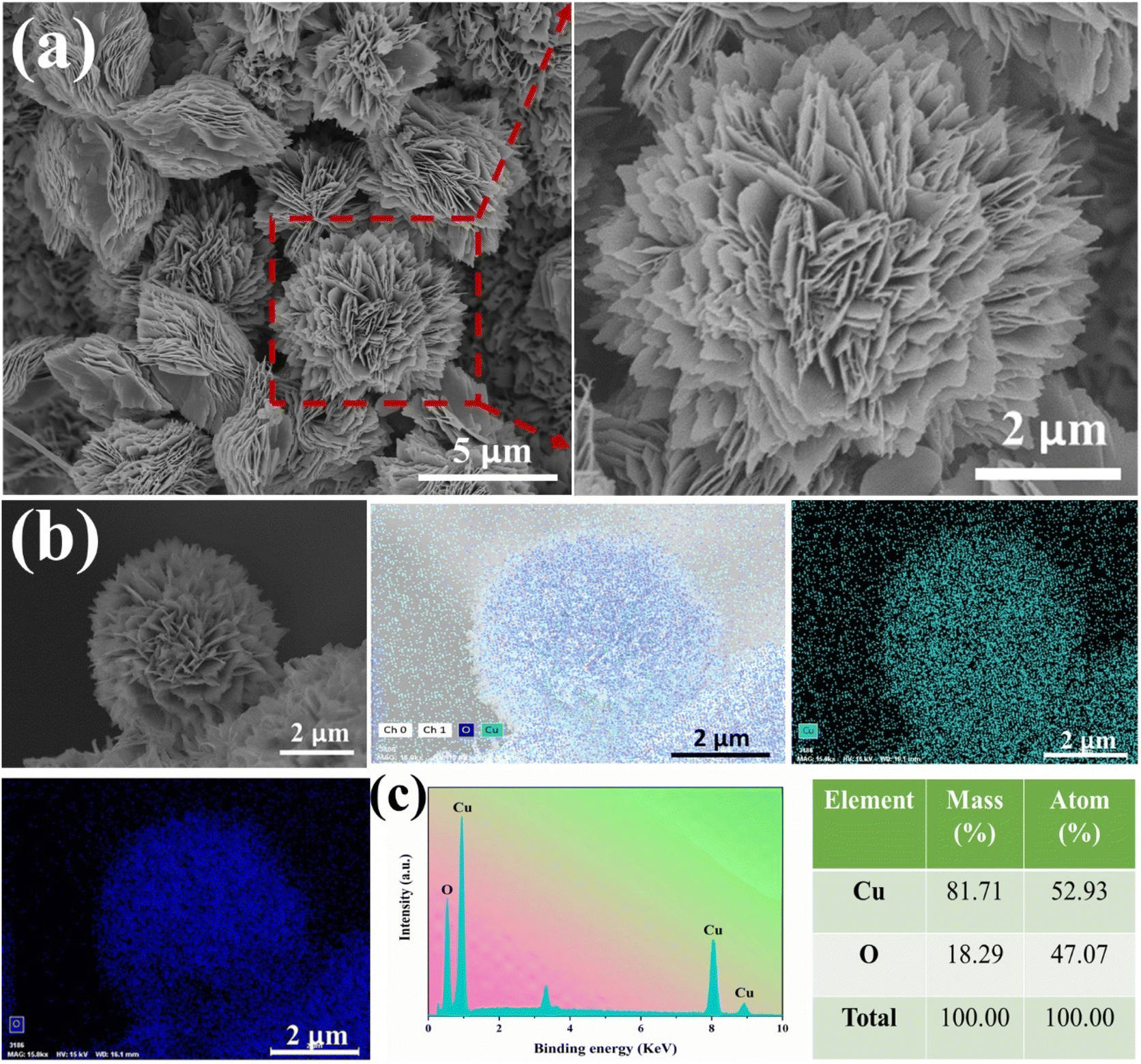 | ||
| Fig. 2 (a) SEM images of CuO-NF@Cu, (b) elemental mapping images of CuO-NF@Cu, (c) EDS spectrum of CuO-NF@Cu. | ||
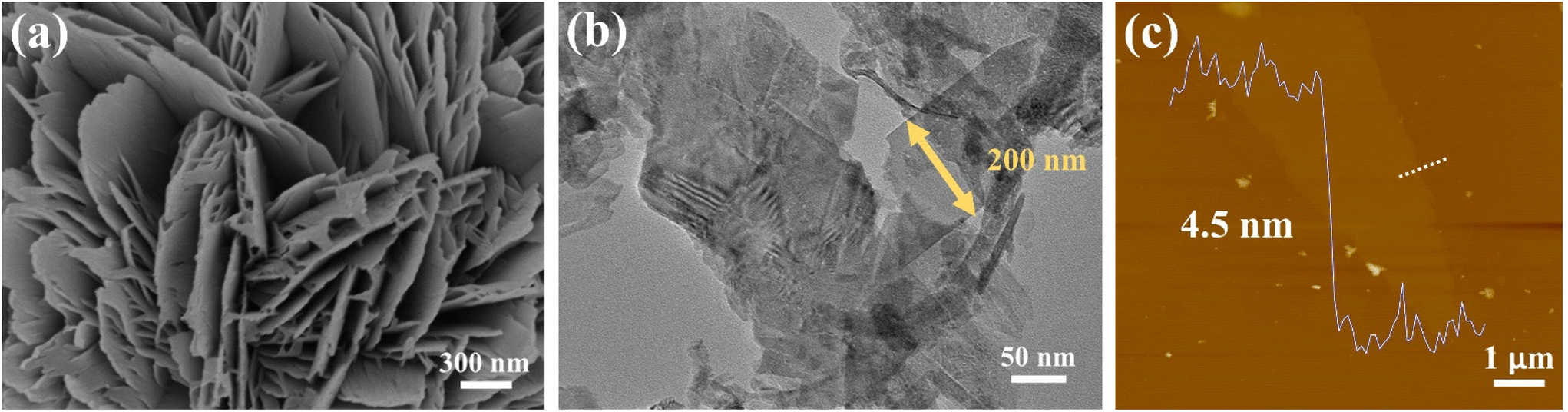 | ||
| Fig. 3 (a) High-magnification SEM and (b) HRTEM images of CuO-NF@Cu at different magnifications; the CuO flakes are about 200 nm in width and 6 nm in thickness. (c) AFM image of the CuO-NF@Cu and the corresponding height profile from the dashed line. | ||
The crystal structure of the catalysts was determined by X-ray diffraction (XRD) and is shown in Fig. S4.† All the catalysts exhibit three high-intensity diffraction peaks at 43.316°, 50.448°, and 74.142°, corresponding to the Cu (111), (200), and (220) planes (Fig. S4a†), respectively (JCPDS Card No. 04-0836), indicating that Cu(OH)2 nanorods and CuO nanoflowers directly grew on the surface of the Cu foam (Fig. S4b–d†). The XRD pattern of Cu(OH)2-NR@Cu in Fig. S4b† exhibits typical diffraction peaks at 34.061°, 39.800°and 53.210° which are respectively assigned to the (002), (130) and (150) planes of the orthorhombic crystal phase of Cu(OH)2 (JCPDS Card No. 13-0420). The XRD pattern of CuO/Cu(OH)2@Cu in Fig. S4c† shows typical diffraction peaks at 36.636° and 42.558°, which correspond to the (002) and (111) planes of the orthorhombic crystal phase of CuO (JCPDS Card No. 80-1917), in addition to the diffraction peaks assigned to Cu(OH)2. For the CuO-NF@Cu catalyst, no other phases were observed except for Cu (JCPDS Card No. 04-0836) and CuO (JCPDS Card No. 80-1917), as shown in Fig. S4d.†
To further investigate the surface chemical composition and valence state of the catalyst, XPS analysis was performed and is given in Fig. S5.† Fig. S5a† shows the XPS spectrum of the CuO-NF@Cu catalyst, in which the characteristic peaks of copper, oxygen, and carbon can be clearly observed. According to the XPS quantitative analysis of the CuO-NF@Cu catalyst, the ratio of oxygen to copper in the catalyst is 1.15:1, which is almost consistent with the ratio of 1.08:1 measured by inductively coupled plasma optical emission spectroscopy (ICP-OES). In the high-resolution Cu 2p spectrum of the catalyst, the two peaks of Cu 2p1/2 and Cu 2p3/2 are located at 952.90 eV and 933.11 eV, respectively (Fig. S5b,† bottom), and are caused by elemental copper. The strong shake-up peaks at 943.65 eV and 963.00 eV indicate the presence of Cu2+ (Fig. S5b,† top) and cannot be found in the spectrum of the copper foam. The main peak of Cu 2p3/2 can be further divided into two peaks, those of Cu2+ from CuO at 935.47 eV and Cu0 at 933.82 eV, because of the inevitable minor amount of Cu remaining unreacted in the process (Fig. S5c†). In addition, the O 1s spectrum (Fig. S5d†) can be divided into two peaks, which belong to the Cu–O bond of CuO at 529.44 eV and a peak at 531.26 eV attributed to hydroxyl groups adsorbed on the surface.
Cathodic electrochemical CO2 reduction to ethylene
CuO-NF@Cu was used as the working electrode for electrochemical CO2 reduction, with an Ag/AgCl electrode as the reference electrode and a platinum foil as the counter electrode. In situ constant current reduction was performed at −0.95 V (vs. RHE) under a flowing CO2 atmosphere. The current decreased sharply in the first 6 min (360 seconds) of electrochemical reduction from ca. 182.0 mA cm−2 to ca. 104.5 mA cm−2 (Fig. 4a, middle) and the black surface of the CuO-NF@Cu catalyst quickly turned reddish-brown (Fig. S6†), indicating that CuO in CuO-NF@Cu can be quickly reduced. To check the composition of the reduced CuO-NF@Cu, X-ray diffraction (XRD) over CuO-NF@Cu and reduced CuO-NF@Cu at different reduction times was conducted and the results are shown in Fig. 4b. The XRD pattern indicates that, besides Cu diffraction peaks, only CuO diffraction peaks were observed in CuO-NF@Cu (spade marks in Fig. 4b). After 60 seconds of electrochemical reduction, diffraction peaks attributed to Cu2O begin to appear (red club marks in Fig. 4b). After 300 seconds of electrochemical reduction, the CuO peak completely disappears, while the Cu2O peak still exists, even if the reduction time is extended to 1800 seconds (0.5 h) and 14400 seconds (4 h). These results implied that surface CuO in CuO-NF@Cu can be reduced into Cu2O which is stable under current reduction conditions. Thus, the cathode catalyst is named Cu2O/Cu-NF@Cu in the following text.
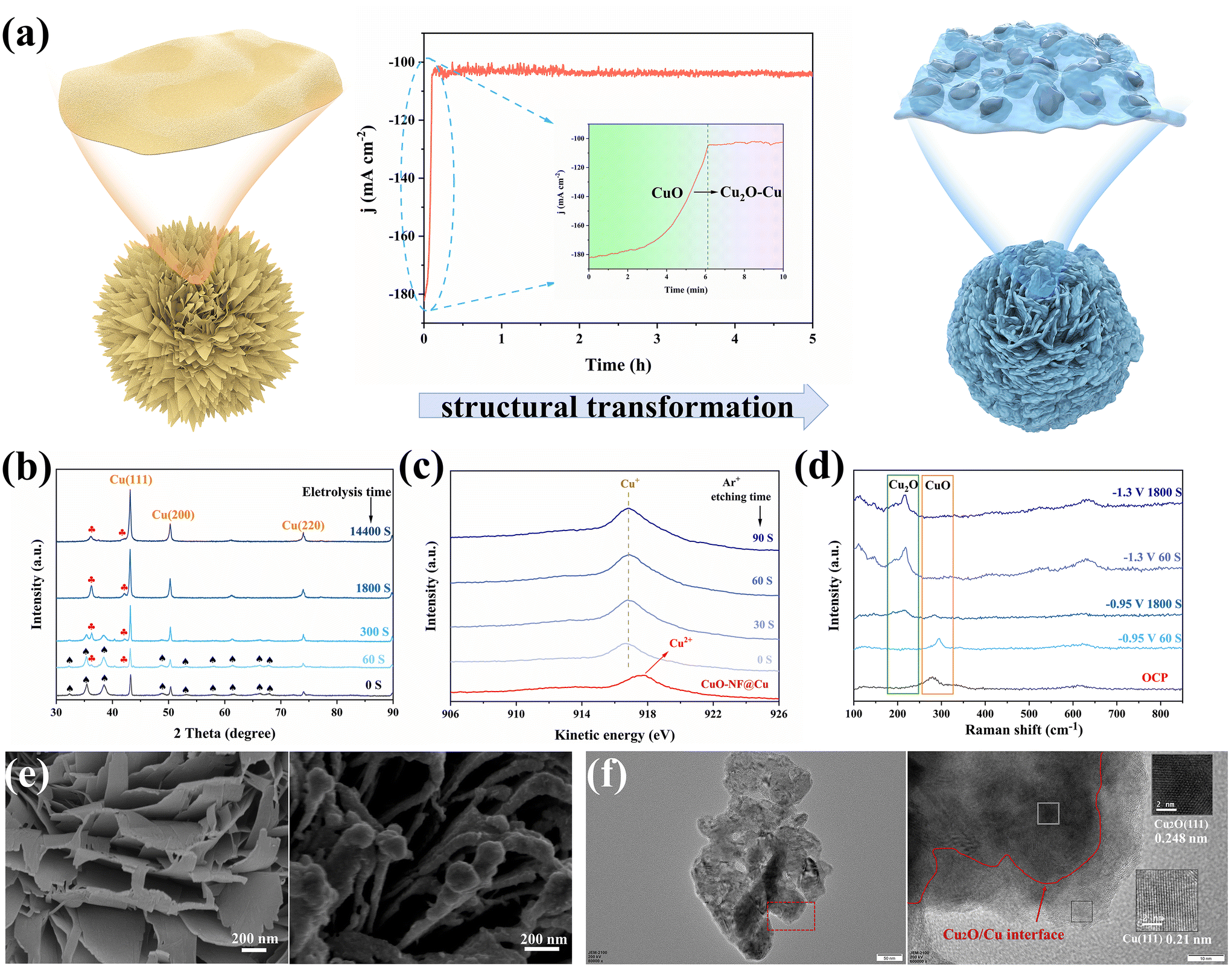 | ||
| Fig. 4 (a) Schematic illustration of morphology changes during the electrochemical reduction of CuO-NF@Cu, (b) XRD patterns of CuO-NF@Cu at different reduction times, (c) Cu LMM Auger spectra of CuO-NF@Cu and Cu2O/Cu-NF@Cu with different Ar+ etching times, (d) in situ Raman spectra of Cu2O/Cu-NF@Cu in different conditions, (e) SEM images of fresh CuO-NF@Cu and Cu2O/Cu-NF@Cu, (f) TEM and HRTEM images of Cu2O/Cu-NF@Cu. | ||
To check the surface and subsurface Cu valence states of CuO-NF@Cu and Cu2O/Cu-NF@Cu, X-ray photoelectron spectroscopy (XPS) and Auger electron spectroscopy (AES) were conducted with different times of Ar+ etching over Cu2O/Cu-NF@Cu, as shown in Fig. 4c and Fig. S7, S8.† The Cu2O/Cu-NF@Cu sample was obtained by 2 hours of electrochemical reduction under the above-mentioned conditions to ensure that its structure was the same as the cathode used in the long-time CO2RR. In CuO-NF@Cu, the Cu LMM Auger peak at 917.4 eV and the typical satellite peaks can be attributed to Cu2+ species. In the XPS spectra of Cu2O/Cu-NF@Cu and Ar+ etched Cu2O/Cu-NF@Cu with etching times from 0–90 seconds, no Cu2+ but only Cu+ peaks were found, indicating that the original Cu2+ species in CuO-NF@Cu were completely reduced to Cu+ after electrolysis. The Cu LMM spectrum shows that Cu+ species can exist in Cu2O/Cu-NF@Cu even after 90 s of Ar+ etching (estimated etching depth of 30 nm), which can completely exclude the surface oxide layer formed by air oxidation (usually <5 nm). Meanwhile, the peaks belonging to the Cu and O elements are compared in Fig. S7 and S8†: the Cu peak intensity increased and the O peak intensity decreased with detection depth increasing, indicating that the original CuO phase was generated over the Cu foam surface. Further in situ Raman spectroscopy was performed to identify the valence of Cu during electrolysis (Fig. 4d). The peaks of Raman shifts at 287, 337, and 622 cm−1 belong to CuO under open circuit potential (OCP) and can be clearly observed. When Cu2O/Cu-NF@Cu was reduced at −0.95 V (vs. RHE) for 60 s, the characteristic peak belonging to CuO became weakened and the peak belonging to Cu2O began to appear.47 After 1800 s, the CuO peak completely disappeared but the Cu2O peak remained. At higher potential (−1.3 V vs. RHE in Fig. 4d), Cu+ can also be retained even after undergoing long-time electrochemical reduction. Therefore, it can be concluded that Cu+ species will be preserved during the electrochemical CO2RR process.
Morphology changes before and after electrochemical reduction were characterized by SEM and TEM. As shown in Fig. 4e and Fig. S9,† SEM images of electrochemically reduced CuO-NF@Cu indicate that the vertically arranged and densely stacked laminated nanostructures are retained. However, the flakes are no longer composed of CuO nanosheets but nanoparticles. Each ultrathin nanosheet transformed into a thicker nanosheet composed of small nanoparticles.
The HRTEM images provide direct evidence for the self-evolution of nanoflakes in CuO-NF@Cu to nanoparticles in Cu2O/Cu-NF@Cu, as shown in Fig. 3b and Fig. S10.† The complete Cu2O/Cu-NF@Cu nanoflakes were reduced and restructured to Cu2O and Cu, resulting in a large number of grain boundary interfaces (GBs) between Cu2O and Cu (Fig. 4f). The large Cu particles were wrapped by Cu2O facets and a Cu (111) plane with a lattice spacing of 0.21 nm was observed on the larger Cu particles, while a Cu2O (111) plane with a lattice spacing of 0.248 nm was observed around the Cu particles. As a result, a large number of Cu2O (111) facets and Cu (111) particles provide rich Cu2O (111)/Cu (111) (Cu+/Cu0) interfaces in the Cu2O/Cu-NF@Cu nanoflakes.
Electrochemical CO2 reduction over the Cu2O/Cu-NF@Cu electrode was evaluated at atmospheric pressure using a three-electrode H-type electrolytic cell setup. Fig. 5a shows the LSV curves of Cu2O/Cu-NF@Cu in 0.5 M KCl water solution saturated with N2 or CO2 at a scan rate of 2 mV s−1 (methods in ESI†). Much higher current was observed in a flowing CO2 atmosphere than in N2 atmosphere at all scan potentials, demonstrating the significant CO2RR performance of Cu2O/Cu-NF@Cu. The reduction products were then detected and the liquid products were mainly ethanol and formate, with a small amount of acetate (Fig. S11†). In the gas products, C2H4 and H2 were the main reduction products (Fig. S12†). Over Cu2O/Cu-NF@Cu at various potentials, the highest Faraday efficiencies (FE) of 70% for C2H4 and 59.6% for C2H4 selectivity were obtained at −0.95 V (Fig. 5b, Fig. S13 and Table S1 in ESI†). Additionally, the FEH2 was only 17.5% at −0.95 V over Cu2O/Cu-NF@Cu. The high proportion of C2+/C1 (CO, CH4, formate) in the CO2RR products further confirms the kinetic advantage of C2H4 and C2+ formation over Cu2O/Cu-NF@Cu (Fig. 5c). According to previous research, the performance observed in stability tests of OD-Cu48,49 catalysts has consistently failed to meet satisfactory levels. Long-term electrolysis at −0.95 V (vs. RHE) over Cu2O/Cu-NF@Cu (Fig. 5d) showed a stable i–t curve with a current density of 104.5 mA cm−2 and high C2H4 FE (FEC2H4 ≈ 70%) over 45 hours.
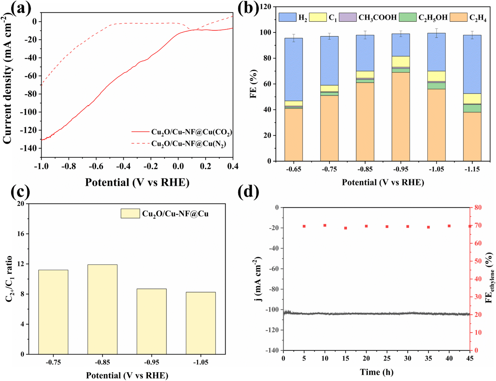 | ||
| Fig. 5 (a) LSV curves over Cu2O/Cu-NF@Cu in Ar and CO2 saturated KCl electrolyte, (b) FEs of products over Cu2O/Cu-NF@Cu, (c) C2+/C1 ratios for CO2RR products, (d) long-term stability test of 45 h at −0.95 V vs. RHE for Cu2O/Cu-NF@Cu. | ||
After long-term testing, XRD characterization of the recovered Cu2O/Cu-NF@Cu catalyst indicated that the characteristic peak of Cu2O was retained in the spectrum (Fig. S14†). XPS analysis showed that Cu2O/Cu-NF@Cu retained a similar Cu/Cu+ interface structure and Cu+ content in the subsurface (Fig. S15†). SEM images showed that the nanoflakes were still stacked densely and orderly after 45 hours of electrolysis without any aggregation, and only a slight increase in the thickness of nanoflakes was observed (Fig. S16a and b†). HRTEM images showed that the Cu2O/Cu (Cu/Cu+) interfaces in the Cu2O/Cu-NF@Cu catalyst were preserved (Fig. S16c and d†), indicating the excellent stability of the Cu2O/Cu-NF@Cu catalyst compared to previous reported catalytic systems (Table S2†). The stable Cu/Cu+ interfaces are believed to be active catalytic sites for C2H4 formation and the detailed mechanism can be found in previous reports.50,51 Moreover, this prepared CuO-NF@Cu is more stable than those previously reported. This work provides a feasible procedure for preparing a stable Cu/Cu+ interface-containing nanocatalyst and verifies its effectiveness in CO2RR and HMFOR.
Anodic high efficiency oxidation of HMF to FDCA
To investigate the activity of the prepared CuO-NF@Cu catalyst in anodic HMF electrochemical oxidation, a series of electrochemical tests was conducted in a three-electrode setup. The linear sweep voltammetry (LSV) curves of CuO-NF@Cu in 0.1 mol L−1 KOH solution with and without HMF are given in Fig. S17.† With HMF, an obviously higher current can be observed than that without HMF under the studied potentials. The copper foam has no effect on the anodic HMF oxidation (Fig. S18†). The electrocatalytic oxidation of HMF to FDCA involves two possible oxidation pathways (Fig. S19†). With constant potential oxidation of HMF at 1.62 V (vs. RHE), the concentration changes of HMF, intermediate products, and FDCA detected by HPLC are shown in Fig. 6a and b. The results show that the HMF concentration in the reaction medium decreased continuously with a concomitant increase of FDCA, along with the passed charges increasing during reaction. Small amounts of intermediate products, such as HMFCA and DFF, were also detected. FFCA was detected as the main accumulated intermediate product during electrolysis, indicating that the oxidation of FFCA to FDCA is the rate-determining step. The current density decreased from 70.3 mA cm−2 in the beginning of reaction to 8.3 mA cm−2 with the decrease of HMF concentration in the reaction medium (Fig. S20†). The passed charge was calculated during electrocatalysis and when 116 C electrons were passed in 45 min, 100% HMF conversion with 99.6% FDCA selectivity and 99.3% FE of FDCA were obtained at 1.62 V (vs. RHE). The HMF conversion and FDCA yield of the CuO-NF@Cu electrode were almost directly proportional to the passed charge (Fig. 6b and S21†).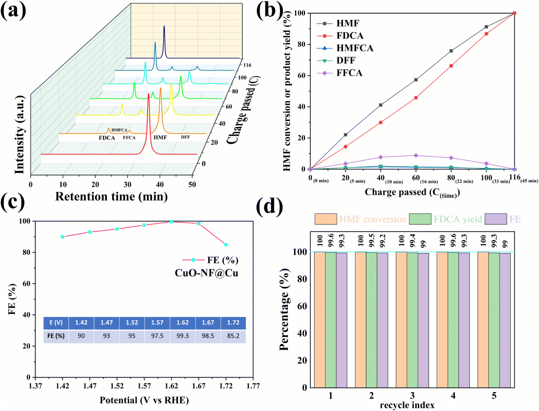 | ||
| Fig. 6 (a) HPLC spectra of HMF reaction solution vs. passed charges during reaction, (b) HMF conversion and products yields vs. passed charges during reaction, (c) FE of FDCA at varied potentials, (d) recycling tests of CuO-NF@Cu. | ||
The high FE of FDCA encouraged us to check its dependence on the potential; the results in Fig. 6c show that the high FDCA FE can be maintained over a wide voltage range but started to decrease when the bias exceeded 1.67 V (vs. RHE) due to the competing OER. To study the stability of CuO-NF@Cu, five consecutive cycles of HMF oxidation were performed at a potential of 1.62 V and are shown in Fig. 6d. High and stable FDCA yield and FE were observed in the 5 recycle tests. Compared with previously reported catalysts (ESI Table S3†), CuO-NF@Cu exhibits comparable performance in the electrochemical oxidation of HMF into FDCA.
Furthermore, the crystal structure, morphology, composition, and element distribution of CuO-NF@Cu after five consecutive electro-oxidation cycles of HMF were investigated by XRD, SEM, EDS mapping, and XPS. XRD patterns (Fig. S22†) and SEM images (Fig. S23†) showed an almost identical crystal lattice and morphology of CuO-NF@Cu before and after long-term electrolysis. Moreover, the composition and element distribution of CuO-NF@Cu (Fig. S24†) and binding energy of Cu 2p (Fig. S25†) did not show significant changes after long-term electrocatalysis. All these results demonstrate the high stability of CuO-NF@Cu, which is crucial for future industrial applications.
Simultaneous cathodic CO2RR and anodic HMFOR over Cu-based nanoflower sheets
Encouraged by the excellent CO2RR and HMFOR performances of the Cu-based nanoflower sheets, we pursued coupling these two half-reactions in one cell. To evaluate the potential application of the catalyst in an industrial-scale reactor, we measured their catalytic performance in a flow cell. CuO-NF@Cu was used directly as the anode electrode. In the cathode, the catalyst CuO-NF@Cu was first sprayed onto carbon paper (Sigracet 39BB) with a gas diffusion layer (GDL, CuO-NF@GDL), followed by constant current cathodic reduction to obtain Cu2O/Cu-NF@GDL. The detailed synthesis method is given in the ESI† (‘Electrocatalysis experiments’ section). The prepared CuO-NF@GDL were characterized by SEM (Fig. S26 and S27†) and the results indicate that CuO-NF@GDL has same nanostructure as CuO-NF@Cu. During the flowing CO2RR-HMFOR process, the CuO-NF on GDL was reduced to Cu2O/Cu-NF (Cu2O/Cu-NF@GDL). After the reaction, the Cu2O/Cu-NF@GDL was recovered and characterized by SEM and HRTEM. Results show that Cu2O/Cu-NF@GDL has a similar nanoflower structure (Fig. S28 and S29†) to Cu2O/Cu-NF@Cu (Fig. 4e, f and Fig. S9, S10†).The coupled CO2RR-HMFOR over Cu-based electrode was tested in a flowing setup, as shown in Fig. 7. The cathode (CuO-NF@GDL) and anode (CuO-NF@Cu) were connected to conductive copper tapes so that they could connect to an external electrochemical workstation. A bipolar membrane and the two electrodes were combined using polytetrafluoroethylene spacers so that a liquid electrolyte could be introduced into the chambers between the anode and the membrane, as well as between the membrane and the cathode. In the CO2RR compartment, gaseous CO2 passed through the gas chamber at the back side of CuO-NF@GDL with a constant flow rate of 15 mL min−1. 100 mL of circular 0.5 M KCl aqueous solution was used as the catholyte and 2 M KOH aqueous solution mixed with or without 10 mM HMF was used as the anolyte. The electrolyte flow rates at both sides were kept at 10 mL min−1 during the reaction. LSV tests in Fig. 8a show that there is an obviously higher current density in coupled CO2RR-HMFOR than in CO2RR-OER (without HMF), HMFOR-HER (without CO2) or HER-OER (without CO2 and HMF), indicating the overall thermodynamic advantage of the CO2RR-HMFOR process over Cu-based nanoflower sheets. Specifically, coupled CO2RR-HMFOR provided a current density of 100 mA cm−2 at a cell voltage of 2.31 V, which was 790 mV lower than the voltage of CO2RR-OER (3.1 V). At cell voltages of 2.5, 2.75, and 3 V, the timed-current curves showed high current densities of 134.5, 188.8 and 245.1 mA cm−2 (Fig. 8b), respectively. The corresponding FEC2H4/FEFDCA values in coupled CO2RR-HMFOR were calculated to be 55.6%/85.5%, 74.5%/96.6%, and 58.6%/88.3%, respectively (Fig. 8c). The stability test of the Cu-based nanoflower sheet catalysts in coupled CO2RR-HMFOR gave a highly stable current density of about 190.0 ± 5.2 mA cm−2 within 5 hours and the FEC2H4/FEFDCA values were maintained at ca. 71 ± 3.8%/93 ± 3.6% (Fig. 8d). The anode CuO-NF@Cu in the coupled reaction was recovered after 5 h and characterized by SEM; the results (Fig. S30†) show that the recovered CuO-NF@Cu maintained its original nanostructure, as shown in Fig. 2 and 3. Thus, the high FE of FDCA and C2H4 in coupled CO2RR-HMFOR can be attributed to the stable nanostructure of the CuO nanoflower sheets in CuO-NF@Cu and the stable Cu/Cu+ interface in Cu2O/Cu-NF@Cu (Fig. S9 and S10†).
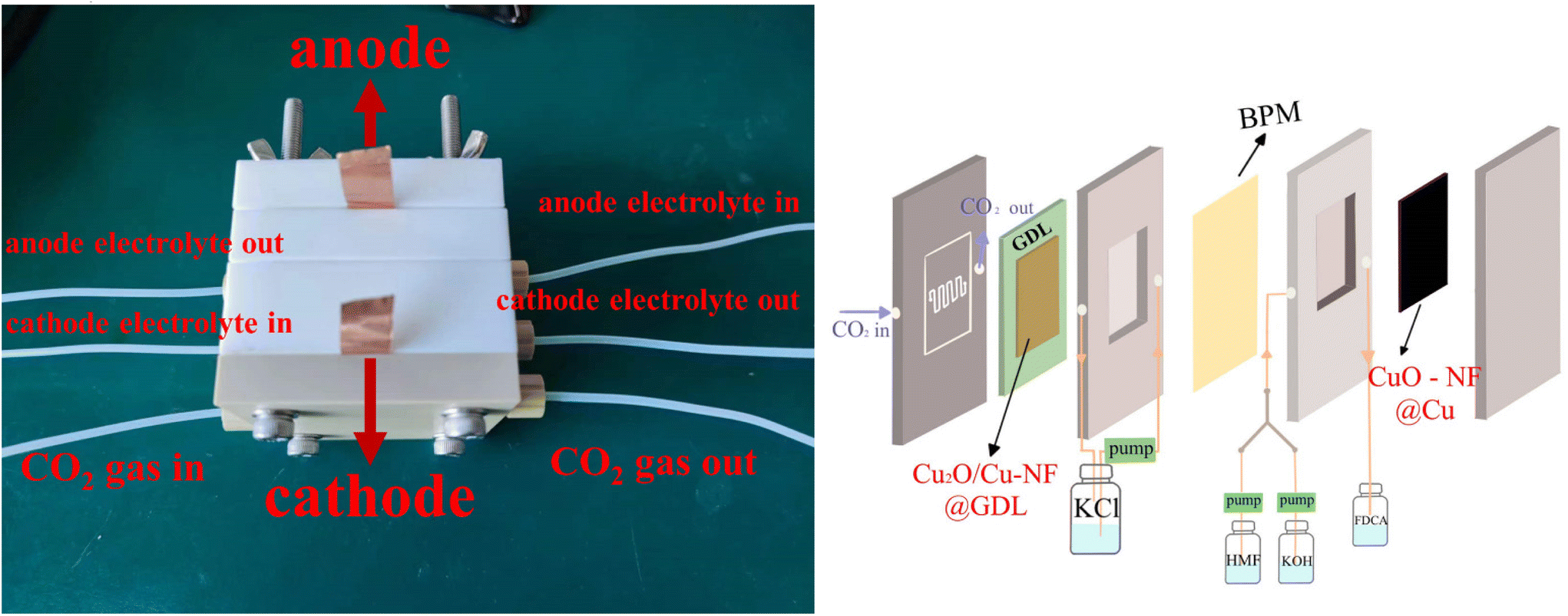 | ||
| Fig. 7 Photo and schematic illustration of the used flow cell. | ||
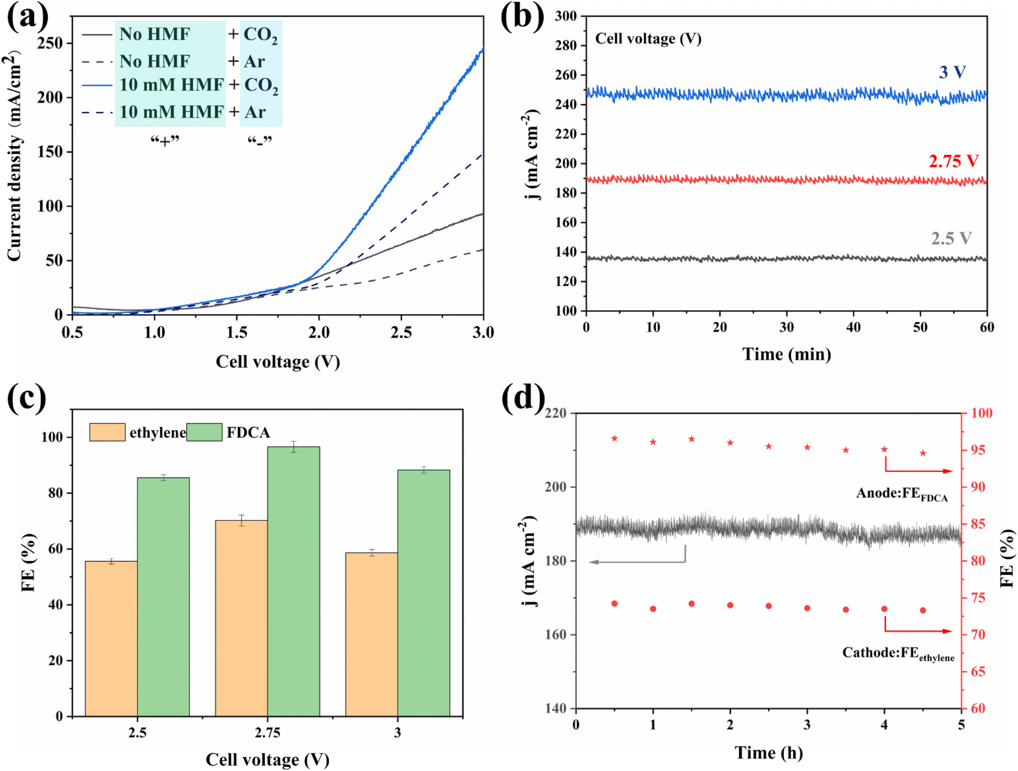 | ||
| Fig. 8 (a) LSV curves recorded in two-electrode setup. “+”: anodic compartment; “−”: cathodic compartment. (b) Chronoamperometry curves under different cell voltages, (c) corresponding FE for CO2RR-HMFOR couple under different cell voltages, (d) stability test of Cu-based nanoflower sheets in CO2RR-HMFOR coupled reaction under a cell voltage of 2.75 V. | ||
Conclusions
In this work, foam Cu was easily modified to a nanoflower CuO-covered Cu foam catalyst, where CuO is composed of a stable structure of nanosheets. In CO2RR, CuO-NF@Cu can be quickly reduced to a nanoflower-shaped Cu2O/Cu-NF@Cu, which has a stable nanoparticle structure and stable Cu+/Cu interface. At a reduction potential of −0.95 V (vs. RHE), a high C2H4 FE up to 70% with a current density above 100 mA cm−2 can be obtained. In HMFOR, CuO-NF@Cu shows excellent catalytic activity in the oxidation of HMF into FDCA. At a constant potential of 1.62 V (vs. RHE) and passed charge of 116 C, the FE of FDCA reached 99.3%. In coupled CO2RR-HMFOR with the above Cu-based nanoflower electrocatalysts, a current density up to 188.8 mA cm−2 at a cell voltage of 2.75 V can be obtained. Moreover, FE vales of FDCA and C2H4 up to 74.5% and 96.6%, respectively, in the coupled CO2RR-HMFOR were achieved. The microstructure of the Cu-based nanoflower catalyst maintained stability and gave above 180.0 mA cm−2 current density within 5 h of testing. This work shows that an easily prepared Cu-based catalyst can be used as a highly efficient electrocatalyst to achieve high-value products by the oxidation of biomass platform compounds in the anode and the reduction of CO2 into high-value C2H4 in the cathode. With the development of efficient electrocatalysts, renewable energy can be used to achieve the resource utilization of CO2 produced from fossil resources while also upgrading renewable biomass resources.Conflicts of interest
There are no conflicts to declare.Acknowledgements
This work was financially supported by the National Natural Science Foundation of China (Grant 21805145, 22002065), the Department of Science and Technology of Shandong Province (ZR2020QB060, ZR2019BB068), and the funding support from Qilu University of Technology (Shandong Academy of Sciences) (2022PY072). Science and Technology Plan Project of Shandong Provincial University (J12LA02), Program for Scientific Research Innovation Team in Colleges and Universities of Shandong Province.References
- J. P. Gattuso, A. Magnan, R. Bille, W. W. Cheung, E. L. Howes and F. Joos, et al., Oceanography. Contrasting futures for ocean and society from different anthropogenic CO(2) emissions scenarios, Science, 2015, 349(6243), aac4722 CrossRef PubMed.
- C. Hepburn, E. Adlen, J. Beddington, E. A. Carter, S. Fuss and N. Mac Dowell, et al., The technological and economic prospects for CO(2) utilization and removal, Nature, 2019, 575(7781), 87–97 CrossRef CAS PubMed.
- H. S. Shafaat and J. Y. Yang, Uniting biological and chemical strategies for selective CO2 reduction, Nat. Catal., 2021, 4(11), 928–933 CrossRef.
- P. Zhu and H. Wang, High-purity and high-concentration liquid fuels through CO2 electroreduction, Nat. Catal., 2021, 4(11), 943–951 CrossRef CAS.
- Y. Li, C.-Z. Huo, H.-J. Wang, Z.-X. Ye, P.-P. Luo and X.-X. Cao, et al., Coupling CO2 reduction with CH3OH oxidation for efficient electrosynthesis of formate on hierarchical bifunctional CuSn alloy, Nano Energy, 2022, 98, 107277 CrossRef CAS.
- S. N. Sun, L. Z. Dong, J. R. Li, J. W. Shi, J. Liu and Y. R. Wang, et al., Redox-Active Crystalline Coordination Catalyst for Hybrid Electrocatalytic Methanol Oxidation and CO(2) Reduction, Angew. Chem., Int. Ed., 2022, 61(34), e202207282 CrossRef CAS PubMed.
- Q. Liu, J. Lin, H. Cheng, L. Wei and F. Wang, Simultaneous co-Photocatalytic CO(2) Reduction and Ethanol Oxidation towards Synergistic Acetaldehyde Synthesis, Angew. Chem., Int. Ed., 2023, 62(13), e202218720 CAS.
- X. She, Y. Wang, H. Xu, S. C. E. Tsang and S. P. Lau, Challenges and Opportunities in Electrocatalytic CO(2) Reduction to Chemicals and Fuels, Angew. Chem., Int. Ed., 2022, 61(49), e202211396 CrossRef CAS PubMed.
- D. Li, K. Yang, J. Lian, J. Yan and S. Liu, Powering the World with Solar Fuels from Photoelectrochemical CO 2 Reduction: Basic Principles and Recent Advances, Adv. Energy Mater., 2022, 12(31), 2201070 CrossRef CAS.
- J. Gu, S. Liu, W. Ni, W. Ren, S. Haussener and X. Hu, Modulating electric field distribution by alkali cations for CO2 electroreduction in strongly acidic medium, Nat. Catal., 2022, 5(4), 268–276 CrossRef CAS.
- J. Y. T. Kim, P. Zhu, F.-Y. Chen, Z.-Y. Wu, D. A. Cullen and H. Wang, Recovering carbon losses in CO2 electrolysis using a solid electrolyte reactor, Nat. Catal., 2022, 5(4), 288–299 CrossRef CAS.
- J. Timoshenko, A. Bergmann, C. Rettenmaier, A. Herzog, R. M. Arán-Ais and H. S. Jeon, et al., Steering the structure and selectivity of CO2 electroreduction catalysts by potential pulses, Nat. Catal., 2022, 5(4), 259–267 CrossRef CAS.
- R. Li, K. Xiang, Z. Peng, Y. Zou and S. Wang, Recent Advances on Electrolysis for Simultaneous Generation of Valuable Chemicals at both Anode and Cathode, Adv. Energy Mater., 2021, 11(46), 2102292 CrossRef CAS.
- D. Wang, N. He, L. Xiao, F. Dong, W. Chen and Y. Zhou, et al., Coupling Electrocatalytic Nitric Oxide Oxidation over Carbon Cloth with Hydrogen Evolution Reaction for Nitrate Synthesis, Angew. Chem., Int. Ed., 2021, 60(46), 24605–24611 CrossRef CAS PubMed.
- T. Wang, L. Tao, X. Zhu, C. Chen, W. Chen and S. Du, et al., Combined anodic and cathodic hydrogen production from aldehyde oxidation and hydrogen evolution reaction, Nat. Catal., 2021, 5(1), 66–73 CrossRef.
- Á. Vass, B. Endrődi and C. Janáky, Coupling electrochemical carbon dioxide conversion with value-added anode processes: An emerging paradigm, Curr. Opin. Electrochem., 2021, 25, 100621 CrossRef.
- S. Choi, M. Balamurugan, K. G. Lee, K. H. Cho, S. Park and H. Seo, et al., Mechanistic Investigation of Biomass Oxidation Using Nickel Oxide Nanoparticles in a CO(2)-Saturated Electrolyte for Paired Electrolysis, J. Phys. Chem. Lett., 2020, 11(8), 2941–2948 CrossRef CAS PubMed.
- J. Bi, Q. Zhu, W. Guo, P. Li, S. Jia and J. Liu, et al., Simultaneous CO2 Reduction and 5-Hydroxymethylfurfural Oxidation to Value-Added Products by Electrocatalysis, ACS Sustainable Chem. Eng., 2022, 10(24), 8043–8050 CrossRef CAS.
- J. Woo, B. C. Moon, U. Lee, H.-S. Oh, K. H. Chae and Y. Jun, et al., Collaborative Electrochemical Oxidation of the Alcohol and Aldehyde Groups of 5-Hydroxymethylfurfural by NiOOH and Cu(OH)2 for Superior 2,5-Furandicarboxylic Acid Production, ACS Catal., 2022, 12(7), 4078–4091 CrossRef CAS.
- L. Jiang, A. Gonzalez-Diaz, J. Ling-Chin, A. Malik, A. P. Roskilly and A. J. Smallbone, PEF plastic synthesized from industrial carbon dioxide and biowaste, Nat. Sustainability, 2020, 3(9), 761–767 CrossRef.
- W. Yang, X. Tang, W. Li, X. Luo, C. Zhang and C. Shen, Fast and continuous synthesis of 2,5-furandicarboxylic acid in a micropacked-bed reactor, Chem. Eng. J., 2022, 442, 136110 CrossRef CAS.
- S. Li, M. Dong, J. Yang, X. Cheng, X. Shen and S. Liu, et al., Selective hydrogenation of 5-(hydroxymethyl)furfural to 5-methylfurfural over single atomic metals anchored on Nb(2)O(5), Nat. Commun., 2021, 12(1), 584 CrossRef CAS PubMed.
- P. Zhou, X. Lv, S. Tao, J. Wu, H. Wang and X. Wei, et al., Heterogeneous-Interface-Enhanced Adsorption of Organic and Hydroxyl for Biomass Electrooxidation, Adv. Mater., 2022, 34(42), e2204089 CrossRef PubMed.
- J. Cui, X. Lu, M. Guo, M. Zhang, L. Sun and J. Xiong, et al., Construction of a g-C3N4-driven photocatalytic system for boosted biomass-derived alcohol oxidation: a promising route towards sustainable biomass valorization, Catal. Sci. Technol., 2023, 13(4), 940–957 RSC.
- Z. Chen, H. Zhou, F. Kong and M. Wang, Piezocatalytic oxidation of 5-hydroxymethylfurfural to 5-formyl-2-furancarboxylic acid over Pt decorated hydroxyapatite, Appl. Catal., B, 2022, 309, 121281 CrossRef CAS.
- T. Xia, W. Gong, Y. Chen, M. Duan, J. Ma and X. Cui, et al., Sunlight-Driven Highly Selective Catalytic Oxidation of 5-Hydroxymethylfurfural Towards Tunable Products, Angew. Chem., Int. Ed., 2022, 61(29), e202204225 CrossRef CAS PubMed.
- Z.-W. Yang, J.-M. Chen, L.-Q. Qiu, W.-J. Xie and L.-N. He, Solar energy-driven electrolysis with molecular catalysts for the reduction of carbon dioxide coupled with the oxidation of 5-hydroxymethylfurfural, Catal. Sci. Technol., 2022, 12, 5495–5500 RSC.
- S. Choi, M. Balamurugan, K. G. Lee, K. H. Cho, S. Park and H. Seo, et al., Mechanistic Investigation of Biomass Oxidation Using Nickel Oxide Nanoparticles in a CO2-Saturated Electrolyte for Paired Electrolysis, J. Phys. Chem. Lett., 2020, 11(8), 2941–2948 CrossRef CAS PubMed.
- X. Wei, Y. Li, L. Chen and J. Shi, Formic Acid Electro-Synthesis by Concurrent Cathodic CO2 Reduction and Anodic CH3 OH Oxidation, Angew. Chem., Int. Ed., 2021, 60(6), 3148–3155 CrossRef CAS PubMed.
- X. Pang, H. Bai, H. Zhao, W. Fan and W. Shi, Efficient Electrocatalytic Oxidation of 5-Hydroxymethylfurfural Coupled with 4-Nitrophenol Hydrogenation in a Water System, ACS Catal., 2022, 12(2), 1545–1557 CrossRef CAS.
- Z.-W. Yang, J.-M. Chen, L.-Q. Qiu, W.-J. Xie and L.-N. He, Solar energy-driven electrolysis with molecular catalysts for the reduction of carbon dioxide coupled with the oxidation of 5-hydroxymethylfurfural, Catal. Sci. Technol., 2022, 12(18), 5495–5500 RSC.
- O. Simoska, Z. Rhodes, S. Weliwatte, J. R. Cabrera-Pardo, E. M. Gaffney and K. Lim, et al., Advances in Electrochemical Modification Strategies of 5-Hydroxymethylfurfural, ChemSusChem, 2021, 14(7), 1674–1686 CrossRef CAS PubMed.
- Y. Yang and T. Mu, Electrochemical oxidation of biomass derived 5-hydroxymethylfurfural (HMF): pathway, mechanism, catalysts and coupling reactions, Green Chem., 2021, 23(12), 4228–4254 RSC.
- D. J. Chadderdon, L. Xin, J. Qi, Y. Qiu, P. Krishna and K. L. More, et al., Electrocatalytic oxidation of 5-hydroxymethylfurfural to 2,5-furandicarboxylic acid on supported Au and Pd bimetallic nanoparticles, Green Chem., 2014, 16(8), 3778–3786 RSC.
- X. Lu, K. H. Wu, B. Zhang, J. Chen, F. Li, B. J. Su, P. Q. Yan, J. M. Chen and W. Qi, Highly Efficient Electro-reforming of 5-Hydroxymethylfurfural on Vertically Oriented Nickel Nanosheet/Carbon Hybrid Catalysts: Structure-Function Relationships, Angew. Chem., Int. Ed., 2021, 133, 14649–14656 CrossRef.
- D. Xu, Y. Yang, B. Zhang, Z. Yang, S. Liu and T. Mu, Deep Eutectic Solvent-Induced In Situ Etching and Phosphorization to Form Nickel Phosphides for Electrooxidation of 5-Hydroxymethylfurfural, ChemSusChem, 2022, e202200822 CAS.
- D.-H. Nam, B. J. Taitt and K.-S. Choi, Copper-Based Catalytic Anodes To Produce 2,5-Furandicarboxylic Acid, a Biomass-Derived Alternative to Terephthalic Acid, ACS Catal., 2018, 8(2), 1197–1206 CrossRef CAS.
- M. Sun, Y. Wang, C. Sun, Y. Qi, J. Cheng and Y. Song, et al., Nitrogen-doped Co3O4 nanowires enable high-efficiency electrochemical oxidation of 5-hydroxymethylfurfural, Chin. Chem. Lett., 2022, 33(1), 385–389 CrossRef CAS.
- Y. Sun, J. Wang, Y. Qi, W. Li and C. Wang, Efficient Electrooxidation of 5-Hydroxymethylfurfural Using Co-Doped Ni3 S2 Catalyst: Promising for H2 Production under Industrial-Level Current Density, Adv. Sci., 2022, 9(17), e2200957 CrossRef PubMed.
- H. Huang, C. Yu, X. Han, H. Huang, Q. Wei, W. Guo, Z. Wang and J.S. Qiu, Ni, Co hydroxide triggers electrocatalytic production of high-purity benzoic acid over 400 mA cm-2, Energy Environ. Sci., 2020, 13, 4990–4999 RSC.
- B. You, X. Liu, N. Jiang and Y. Sun, A General Strategy for Decoupled Hydrogen Production from Water Splitting by Integrating Oxidative Biomass Valorization, J. Am. Chem. Soc., 2016, 138(41), 13639–13646 CrossRef CAS PubMed.
- H. Sheng, A. N. Janes, R. D. Ross, H. Hofstetter, K. Lee and J. R. Schmidt, et al., Linear paired electrochemical valorization of glycerol enabled by the electro-Fenton process using a stable NiSe2 cathode, Nat. Catal., 2022, 5(8), 716–725 CrossRef CAS.
- C. Chen, X. Yan, S. Liu, Y. Wu, Q. Wan, X. Sun, Q. Zhu, H. Liu, L. Zheng, H. Wu and B. Han, Highly Efficient Electroreduction of CO2 to C2+ Alcohols on Heterogeneous Dual Active Sites, Angew. Chem., Int. Ed., 2020, 14, 16601–16606 Search PubMed.
- J. Zhang, Y. Wang, Z. Li, S. Xia, R. Cai and L. Ma, et al., Grain Boundary-Derived Cu(+) /Cu(0) Interfaces in CuO Nanosheets for Low Overpotential Carbon Dioxide Electroreduction to Ethylene, Adv. Sci., 2022, 9(21), e2200454 CrossRef PubMed.
- H. Li, T. Liu, P. Wei, L. Lin, D. Gao, G. Wang and X. Bao, et al., High-Rate CO2 Electroreduction to C2+ Products over a Copper-Copper Iodide Catalyst, Angew. Chem., Int. Ed., 2021, 133(26), 14450–14454 CrossRef.
- Z. Yin, J. Yu, Z. Xie, S.-W. Yu, L. Zhang, T. Akauola, J. Chen, W. Huang, L. Qi and S. Zhang, et al., Hybrid Catalyst Coupling Single-Atom Ni and Nanoscale Cu for Efficient CO2 Electroreduction to Ethylene, J. Am. Chem. Soc., 2022, 144(45), 20931–20938 CrossRef CAS PubMed.
- H. S. Jeon, J. Timoshenko, C. Rettenmaier, A. Herzog, A. Yoon and S. W. Chee, et al., Selectivity Control of Cu Nanocrystals in a Gas-Fed Flow Cell through CO2 Pulsed Electroreduction, J. Am. Chem. Soc., 2021, 143(19), 7578–7587 CrossRef CAS PubMed.
- Y. Wang, Z. Wang, C.-T. Dinh, J. Li, A. Ozden and M. G. Kibria, et.al., Catalyst synthesis under CO2 electroreduction favours faceting and promotes renewable fuels electrosynthesis, Nat. Catal., 2019, 3(2), 98–106 CrossRef.
- W. Zhang, C. Huang, Q. Xiao, L. Yu, L. Shuai and P. An, et al., Atypical Oxygen-Bearing Copper Boosts Ethylene Selectivity toward Electrocatalytic CO2 Reduction, J. Am. Chem. Soc., 2020, 142(26), 11417–11427 CrossRef CAS PubMed.
- Y. Yao, Y. Zhou, X. Liu, Y. Li, D. Wang and X. Chi, et al., Restraining lattice oxygen of Cu2O by enhanced Cu–O hybridization for selective and stable production of ethylene with CO2 electroreduction, J. Mater. Chem. A, 2022, 10(39), 20914–20923 RSC.
- J. Kim, W. Choi, J. W. Park, C. Kim, M. Kim and H. Song, Branched Copper Oxide Nanoparticles Induce Highly Selective Ethylene Production by Electrochemical Carbon Dioxide Reduction, J. Am. Chem. Soc., 2019, 141(17), 6986–6994 CrossRef CAS PubMed.
Footnote |
| † Electronic supplementary information (ESI) available. See DOI: https://doi.org/10.1039/d3gc01420g |
| This journal is © The Royal Society of Chemistry 2023 |