
Electrosynthesis of N,N-dimethylformamide from market-surplus trimethylamine coupled with hydrogen production†
Meng
Jin‡
a,
An-Zhen
Li‡
a,
Ye
Wang
a,
Jing
Li
a,
Hua
Zhou
b,
Bi-Jie
Li
 *a and
Haohong
Duan
*ac
*a and
Haohong
Duan
*ac
aDepartment of Chemistry, Tsinghua University, Beijing 100084, China. E-mail: bijieli@mail.tsinghua.edu.cn; hhduan@mail.tsinghua.edu.cn
bState Key Laboratory of Chemical Resource Engineering, College of Chemistry, Beijing University of Chemical Technology, Beijing 100029, China
cHaihe Laboratory of Sustainable Chemical Transformations, Tianjin 300192, China
First published on 10th July 2023
Abstract
N,N-Dimethylformamide (DMF) is a universal solvent with wide applications across various industries. Current industrial synthesis requires high temperature and high pressure, starting from fossil-based carbon monoxide and dimethylamine (DMA). Herein, we report a green and electrochemical strategy to produce DMF under ambient conditions through direct oxidation of trimethylamine (TMA), which is a surplus chemical in DMA manufacturing. DMF production with 80% yield and >50% faradaic efficiency was achieved in an H-cell reactor over a graphite anode, coupled with hydrogen production at the cathode. Mechanistic investigations show that the reaction occurs through two-phase oxidation and that an aminal serves as the key intermediate. To achieve continuous DMF production, we set up a membrane-electrode assembly (MEA) flow reactor (2 cm × 2 cm), achieving a DMF productivity of 25 μmol h−1 and a faradaic efficiency of 40%. To further increase the productivity, we fabricated another membrane-free flow reactor (8 cm × 9 cm), delivering a high formation rate (550 μmol h−1) with high selectivity (>90%) at a constant current of 3 A in a 100-hour test. This study offers a unique opportunity to utilize electricity to drive surplus chemical utilization under ambient conditions, contributing to the sustainability of the chemical industry in the future.
Introduction
Due to its high aprotic nature, wide liquid range, and low volatility, N,N-dimethylformamide (DMF) is known as a universal solvent with wide applications across various industries.1,2 For example, DMF is a major solvent used in the production of acrylic fibres and the plastic industry. It also serves as a solvent and crystallization agent in the manufacture of pharmaceuticals, agrochemicals, adhesives and surface coatings. In addition, DMF functions as a multipurpose building block with diverse applications in organic synthesis.3,4 Because of its widespread applications, the DMF market is predicted to grow from $2.3 billion in 2022 to $2.7 billion by 2027.5 Although there is concern about the health and safety issues of DMF,1 the demand for DMF would continuously increase before a greener alternative is developed. Conventionally, DMF is produced via one-step synthesis using fossil-based carbon monoxide (CO) and dimethylamine (DMA) as the feedstocks, in which DMA is provided by a methanol amination process over α-Al2O3 (Scheme 1a).6,7 Despite the high reaction efficiency (e.g., productivity and product purity), this method requires a high temperature (50–200 °C) and high pressure (0.5–11 MPa) (Scheme 1b). Considering the large market demand, it is highly desirable to develop less energy-intensive and safe methods for DMF production starting from an economical route.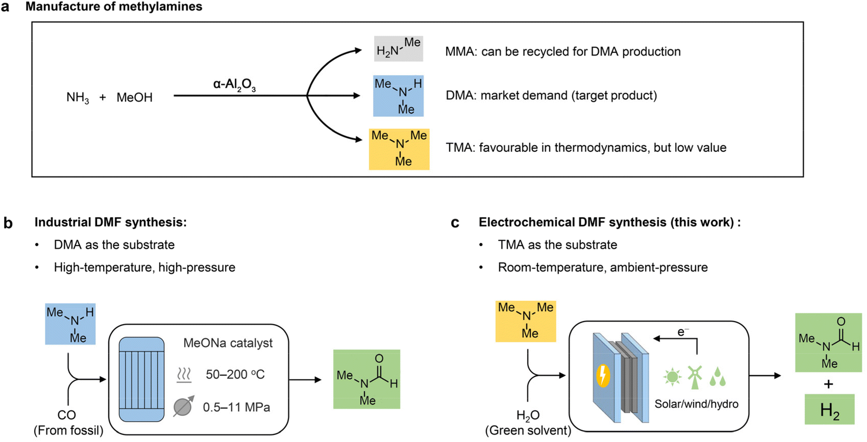 | ||
| Scheme 1 Design concept. (a) Manufacture of methylamine products in industry. (b) Industrial DMF synthesis. (c) Electrochemical synthesis of DMF from TMA. | ||
Industrially, DMA is synthesized through methanol amination,8 but monomethylamine (MMA) and trimethylamine (TMA) are simultaneously generated with much lower market values compared to DMA (Scheme 1a). It is feasible to recycle MMA for DMA production; nevertheless, it is more difficult and costly to recycle TMA. Moreover, TMA is thermodynamically more favourable than the other two amines, with an equilibrium ratio of MMA![[thin space (1/6-em)]](https://www.rsc.org/images/entities/char_2009.gif) :DMA:TMA close to 17:21:62 (when the ammonia:methanol molar ratio is 1:1).9,10 Consequently, the large TMA distribution in the products greatly limits the overall efficiency for DMA production. Although advanced silica–alumina catalysts were reported to suppress TMA formation via methanol animation to some extent,11–13 the development of a cost-effective and less energy-intensive method to directly channel TMA into DMF production is desirable to enhance the synthetic efficiency of DMA.
:DMA:TMA close to 17:21:62 (when the ammonia:methanol molar ratio is 1:1).9,10 Consequently, the large TMA distribution in the products greatly limits the overall efficiency for DMA production. Although advanced silica–alumina catalysts were reported to suppress TMA formation via methanol animation to some extent,11–13 the development of a cost-effective and less energy-intensive method to directly channel TMA into DMF production is desirable to enhance the synthetic efficiency of DMA.
To fill this gap, we envisage that direct TMA oxidation to DMF would be a green and economically promising route. The direct oxidation of amines to amides is a particularly useful process in organic synthesis due to the widespread occurrence of amides across diverse organic molecules.14 This oxidation is usually achieved through thermocatalytic15–17 or photocatalytic18–20 approaches, where metal catalysts, hazardous oxidants or special additives are usually necessary. More importantly, this oxidation usually occurs preferentially at the α secondary carbon instead of the primary carbon with few exceptions,21,22 because of the stability of the corresponding secondary carbon radical. As a result, due to the low boiling point, stronger methyl C–H bonds and formation of side-products such as trimethylamine oxide,23 the conventional approaches have rarely been successfully applied to TMA oxidation.23–25
 | (1) |
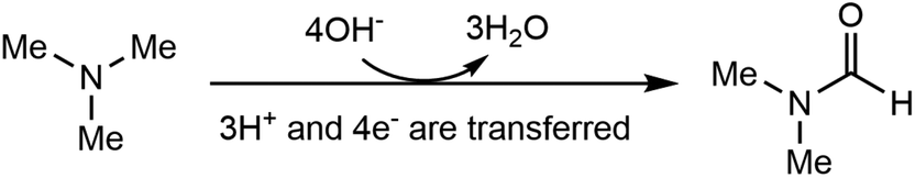
Electrosynthesis of value-added chemicals and fuels has emerged as a green and sustainable method,26–33 for its ambient conditions (e.g., room temperature and ambient pressure) and the use of renewable electricity (e.g., solar, wind, hydro).34 Based on our research interest in the electrosynthesis of valuable chemicals from biomass- and plastic-derived compounds,35–37 we recently questioned whether an electrochemical method can be developed to accomplish the direct oxidation of TMA to DMF. If successful, this process will generate value-added chemicals at the anode, with an additional benefit of simultaneous hydrogen (H2) production at the cathode, a green energy carrier with a large market demand.38,39 Although the Shono-type reaction indicates that amines and carbamates can be oxidized at the anode,40 additives (Lewis acids,41 aminoxyl mediators42–44 and halide ions45) are necessary, in which the Lewis acid mediates the generation of a reactive iminium ion intermediate, while aminoxyl mediators and halide ions serve as the redox mediators. The use of these additives may increase the product separation cost and feedstock cost, thus restricting the practical applications. In addition, the Shono-type reactions are often conducted in organic solution, while aqueous solution is environmentally more desirable. According to eqn (1), direct electrochemical oxidation of TMA to DMF is a multi-proton and multi-electron process (4e− and 3H+ are transferred); thus the challenge lies in the development of an efficient electrochemical system without any mediator and using only water as the oxidant to achieve high selectivity of DMF at a moderate potential.
Herein, we report an electrochemical oxidation strategy to synthesize DMF directly from TMA, which was conducted at ambient temperature and pressure in an aqueous medium without any additives (Scheme 1c). DMF production with 80% yield and >50% faradaic efficiency (FE) was achieved over cost-effective graphite as the anode, coupling with hydrogen production using platinum (Pt) or nickel (Ni) as the cathode. Mechanistic investigations show that a two-phase oxidation is involved, where an aminal serves as the key intermediate for producing DMF. To achieve continuous DMF production, we set up a membrane-electrode assembly (MEA) flow reactor (2 cm × 2 cm), with a DMF productivity of 25 μmol h−1 and a faradaic efficiency of 40%. To further increase the productivity, we fabricated a membrane-free reactor (8 cm × 9 cm) in a single module. In a 100-hour test, a high formation rate (550 μmol h−1) with high selectivity (>90%) at an absolute current of 3 A was maintained. Moreover, a high DMF yield (75%) was obtained in the flow reactor by circulating the electrolyte, and the performance is recyclable without activity loss. In addition, calculations of several important green chemistry metrics—including atom economy (AE), environmental factor (E-factor), and carbon efficiency (CE)—suggest that this method represents a potentially green route to produce DMF.
Results and discussion
Optimization of the reaction conditions
We initiated the electrochemical investigations in a two-compartment, three-electrode H-cell reactor with an anion exchange membrane (AEM). The products were quantitatively analyzed by high performance liquid chromatography (HPLC, Fig. S1–S4†) and 1H nuclear magnetic resonance (1H NMR, Fig. S5 and S6†). DMF, N-methylformamide (NMF), formaldehyde, and formic acid were detected as the products. It should be noted that DMF was not observed at the cathode compartment in the tests, ruling out the possibility that DMF crosses over the membrane. Extensive studies were conducted to identify a suitable electrochemical system, including anode materials, electrolytes, concentrations, and pH (Table S1† and Table 1). We first performed the reaction in 0.7 M K2CO3 with pH 12.2. The reaction did not occur without electricity, suggesting that DMF generation in the following tests is realized by electrochemical oxidation. Several anode catalysts were screened under a constant potential at 1.1 V vs. Hg/HgO (Table S1†). With Pt plate as the anode, TMA oxidation barely occurred (yield of 3% and FE of 5%, entry 1, Table S1†). We then evaluated a nickel–iron layered double hydroxide (NiFe-LDH) loaded carbon paper as the anode (synthesis see Methods in the ESI†), considering its high activity in electrochemical oxidations.46 DMF was observed as the product, but with a moderate yield (31%) and low faradaic efficiency (FE) (6%, entry 2, Table S1†). Further anode material screening includes Ni(OH)2, Ni foam, commercial Pd/C, carbon paper, carbon felt (entries 3–7, Table S1†) and graphite flake (entry 2, Table 1), among which graphite flake shows the highest DMF yield (80%) and FE (56%). In addition, DMA, NMF and formaldehyde were observed as the by-products (Fig. S4–S6†).|
|
||||
|---|---|---|---|---|
| Entry | Catalyst | Electrolyte | Yield (%) | FE (%) |
| a Reaction conditions: graphite flake anode (1 cm × 1 cm), Pt cathode (1 cm × 1 cm), TMA (0.1 mmol), water (5 mL), at 1.1 V vs. Hg/HgO for 2 h at room temperature in an H-type cell. | ||||
| 1 | Graphite flake | 0.7 M KOH | 16 | 2 |
| 2 | Graphite flake | 0.7 M K 2 CO 3 | 80 | 56 |
| 3 | Graphite flake | 0.7 M KH2PO4 | 22 | 21 |
| 4 | Graphite flake | 0.7 M PBS | 19 | 7 |
| 5 | Graphite flake | 0.7 M KCl | 5 | 6 |
| 6 | Graphite flake | 0.1 M K2CO3 | 50 | 37 |
| 7 | Graphite flake | 1.5 M K2CO3 | 66 | 41 |
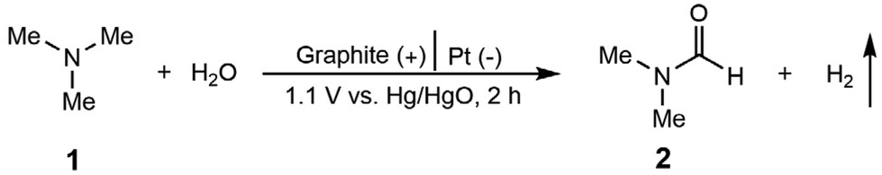
The electrolyte was further optimized using graphite flake as the anode (entries 1–5, Table 1), and K2CO3 delivers the highest DMF yield (entry 2, Table 1). Although complete TMA conversion was observed when KOH was used as the electrolyte, DMF yield was only 16% for 2 h (entry 1, Table 1). With the reaction time extended to 5 h, the DMF yield decreased to 1%, indicating that the use of KOH as the electrolyte probably caused TMA overoxidation or decomposition (Fig. S7†). Low TMA conversions and DMF yields were observed in KH2PO4, PBS and KCl (entries 3–5, Table 1). Based on K2CO3 as the optimal electrolyte, we found that either decreasing (entry 6, Table 1) or increasing (entry 7, Table 1) the K2CO3 concentration reduced the DMF yield. We recognize that electrolyte pH also greatly affects DMF selectivity. By adding 0.7 M KOH into 0.7 M K2CO3 (to increase pH), or adding 0.7 M KHCO3 into 0.7 M K2CO3 (to decrease pH), lower selectivity and FE of DMF were obtained compared with that in 0.7 M K2CO3 with pH 12.2 (Fig. S8†). Based on the above optimizations, using graphite flake as the anode, Pt as the cathode, and 0.7 M K2CO3 with 20 mM TMA as the electrolyte, the efficient electrochemical oxidation of TMA to DMF was realized (DMF yield of 80% and FE of 56%, shown in entry 2, Table 1) in an aqueous medium without any additives under ambient temperature and pressure. These are set as the standard conditions for the following evaluations.
Electrochemical studies
The linear sweep voltammetry (LSV) curves under the optimized conditions are displayed in Fig. 1a. In the absence of TMA, the current density increase is contributed by the OER, and a high potential of 1.21 V vs. Hg/HgO is required to achieve 10 mA cm−2. In sharp contrast, in the presence of 20 mM TMA, a significant reduction of onset potential (0.73 V vs. Hg/HgO) was observed to achieve the same current density. In addition, concerning the reaction thermodynamics, the standard electrode potential (φθ) of the TMA oxidation reaction is 0.32 V vs. RHE (the electrode potential at pH 12.2 is −0.40 V vs. RHE), while that of the oxygen evolution reaction (OER) is 1.23 vs. RHE (the electrode potential at pH 12.2 is 0.51 V vs. RHE), indicating that TMA oxidation is more thermodynamically favorable than the OER (Table S2†). Accordingly, H2 production at the cathode is also enhanced, with the reaction rate increasing from 4.28 mL cm−2 h−1 (without TMA) to 23.51 mL cm−2 h−1 (with TMA) at 1.1 V vs. Hg/HgO with >99% FE (Fig. 1b), which is an indication of the greater energy efficiency of the whole process.47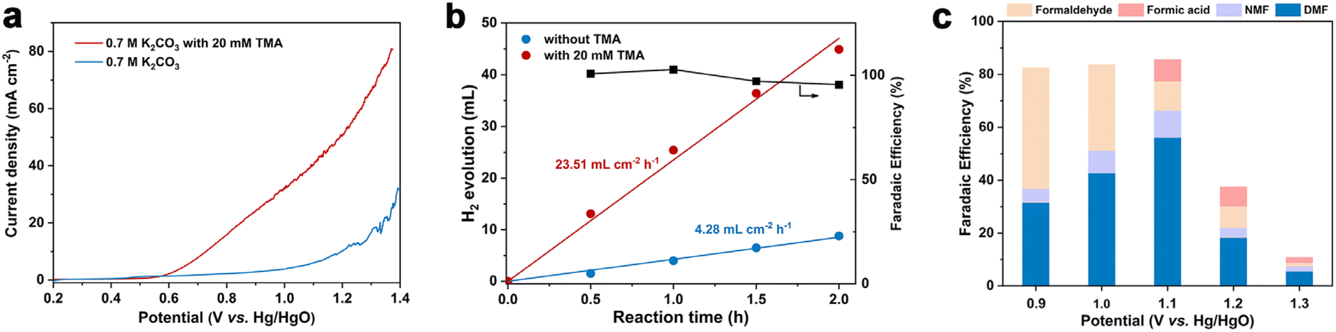 | ||
| Fig. 1 (a) LSV curves of a graphite flake at a scan rate of 5 mV s−1 in 0.7 M K2CO3 with or without 20 mM TMA. (b) H2 production rate and faradaic efficiency at the cathode at 1.1 V vs. Hg/HgO in 0.7 M K2CO3 with or without 20 mM TMA. (c) Faradaic efficiency as a function of applied potential for TMA oxidation. | ||
We then investigated the effect of applied potential on product selectivity. According to the potential range shown in the LSV curve, we performed the reaction at a constant potential from 0.9 to 1.3 V vs. Hg/HgO (Fig. 1c and Table S3†). In the potential range of 0.9–1.1 V vs. Hg/HgO, the DMF yield and FE gradually increased with the increase of potential (Fig. S9a†), while formaldehyde's FE decreased. It is speculated that a slow reaction rate at lower potential may be caused by the accumulation of formaldehyde as a reaction intermediate (discussed later). The DMF yield and FE are the highest when the potential is increased to 1.1 V vs. Hg/HgO (entry 2, Table 1). However, when the potential was further increased to 1.3 V vs. Hg/HgO, both DMF yield and FE significantly decreased. The yield continued to decline with the extension of reaction time, indicating overoxidation of DMF (Fig. S9b†) and the intermediates, as well as the competition of the OER at the high potential (Table S4†). At the same time, it also caused a significant decrease in the faradaic efficiency.
Mechanistic investigations
To gain insights into the reaction mechanism of the efficient electrochemical oxidation of TMA to DMF, we monitored the time course of the electrochemical oxidation process (Fig. 2a). Complete TMA conversion and high yield of DMF (76%) were achieved within 2 hours. DMA and formaldehyde were detected during the reaction, which were probably generated by TMA oxidation via C–N cleavage with subsequent oxidations. We investigated whether formaldehyde is contributed by the electrochemical reduction of CO32− (from the K2CO3 electrolyte) at the cathode followed by a crossover to the anode chamber. No formaldehyde was detected in the cathode chamber (Fig. S10†), thus formaldehyde is solely contributed by TMA oxidation. In addition, the concentration of DMA decreases at longer reaction times, which is likely due to the C–N coupling between DMA and formaldehyde to yield DMF.48,49 To verify this possibility, DMA and formaldehyde were used as the starting materials for the electrochemical reaction (Scheme 2a). The results show that DMF was obtained in a high yield (85%), demonstrating that DMA and formaldehyde are the reaction intermediates during the electrochemical oxidation of TMA to DMF.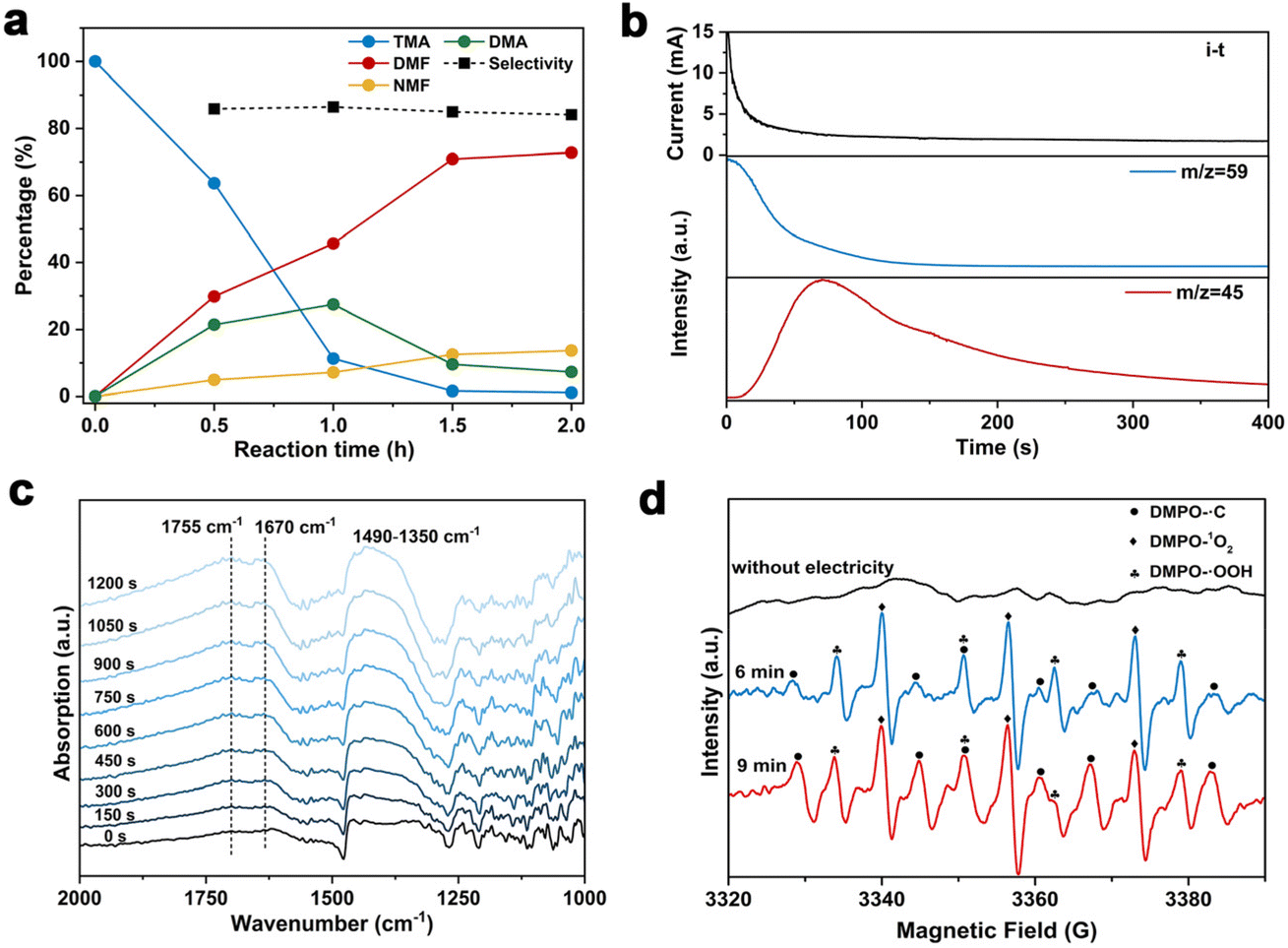 | ||
| Fig. 2 (a) Time-dependent conversions of TMA in 0.7 M K2CO3. (b) DEMS results at 1.1 V vs. Hg/HgO in 0.7 M K2CO3 with 20 mM TMA. (c) In situ IRRAS of the reaction in 0.7 M K2CO3 with 20 mM TMA at 1.1 V vs. Hg/HgO. (d) EPR spectra of the reaction in 0.7 M K2CO3 with 20 mM TMA at 1.1 V vs. Hg/HgO. | ||
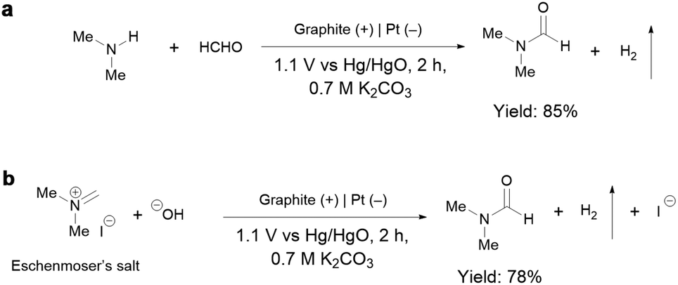 | ||
| Scheme 2 (a) Electrochemical oxidation of DMA and formaldehyde at 1.1 V vs. Hg/HgO under the standard conditions. (b) Electrochemical oxidation of Eschenmoser's salt at 1.1 V vs. Hg/HgO under the standard conditions. | ||
To further understand the reaction mechanism of the electrochemical oxidation of TMA to DMF, differential electrochemical mass spectrometry (DEMS) experiments were carried out to detect the reaction intermediates. The measurement was carried out in the undivided cell, containing 0.7 M K2CO3 with 20 mM TMA, using carbon paper, Pt wire, and Hg/HgO as the working, counter, and reference electrodes, respectively. The DEMS was performed under the standard conditions, as shown in Fig. 2b. The signal with a mass-to-charge ratio (m/z) of 59 kept decreasing, which is assigned to TMA consumption during the reaction. Another signal with a m/z of 45 first increased and then decreased over time, which is assigned to DMA, indicating its generation and then consumption during the measurement. These results are consistent with the above time course study (Fig. 2a). It is reported that during the oxidation of amines to amides, aminal intermediates are formed.50,51 However, the formation of DMF and other reaction intermediates including aminal intermediates was not observed, probably due to their low vaporization ability or instability under the tested conditions. Furthermore, in situ infrared reflection absorption spectroscopy (IRRAS) (Fig. 2c) was conducted in 0.7 M K2CO3 with 20 mM TMA at 1.1 V vs. Hg/HgO for 1200 s. With the prolonging of the reaction time, the peaks at 1670 cm−1 and 1755 cm−1 can be assigned to the vibrational stretching of carbonyl (C![[double bond, length as m-dash]](https://www.rsc.org/images/entities/char_e001.gif) O), which could be attributed to the formation of DMF and formaldehyde.52
O), which could be attributed to the formation of DMF and formaldehyde.52
According to the above analysis that DMA and formaldehyde are formed during the electrochemical oxidation of TMA to DMF, we speculate that TMA might be initially oxidized to an aminal intermediate ((CH3)2NCH2OH), which is then reversibly transformed to DMA and formaldehyde, or further oxidized to DMF. Because the nucleophilic attack of a hydroxide (HO−) to N,N-dimethylmethyleneiminium iodide (namely, Eschenmoser's salt) would generate a (CH3)2NCH2OH intermediate, an electrochemical test was performed using Eschenmoser's salt as the substrate in order to demonstrate that an aminal could be the reaction intermediate. The results show that DMF was obtained in 78% yield (Scheme 2b); therefore (CH3)2NCH2OH is presumably involved as the reaction intermediate. This also explains the higher FE of formaldehyde at lower pH, because the lower pH would promote hydrolysis of the aminal (Fig. S8†).
In order to gain more insights into the reaction mechanism, radical trapping experiments were performed. A decreased yield of DMF after adding 5,5-dimethyl-1-pyrroline N-oxide (DMPO, 15% decrease in yield with 10 mM DMPO, and 25% decrease in yield with 20 mM DMPO, Fig. S11†) was observed, indicating that a radical pathway through a single-electron transfer (SET) process was involved. To further confirm our conjecture, the possible formation of free radicals during the reaction was detected by electron paramagnetic resonance (EPR) study. The measurement was conducted in 0.7 M K2CO3 with 20 mM mmol TMA using 100 mM DMPO as the trapping reagent. Prior to the measurement of EPR, the reaction solution was subjected to constant potential electrolysis (1.1 V vs. Hg/HgO) for 6 minutes to initiate the reaction. The typical signals of ˙C, ˙OOH and 1O2 were detected (Fig. 2d). We speculate that ˙C is attributable to a dimethylaminomethyl radical formed by TMA oxidation,53 and then dimethylaminomethyl radical can be oxidized to an iminium ion and finally to DMF. In addition, ˙OOH and 1O2 radicals are possibly formed by the electrooxidation of water, but they exhibit an insignificant effect on DMF formation. To confirm the role of ˙C radical in DMF formation, we conducted the EPR experiment under reaction conditions with KCl as the electrolyte, in which a much lower DMF yield was obtained (entry 5, Table 1). The radical signal of ˙C with much weaker intensity was observed (Fig. S12†), indicating that the ˙C radical is an intermediate during the electrochemical oxidation of TMA to DMF.
Based on the above discussions and previous studies,54,55 we propose that the electrochemical oxidation of TMA to DMF proceeds through the following pathway (Scheme 3). TMA (1) is initially oxidized to an amino radical cation (1a) via single electron transfer (SET). 1a is then deprotonated to give an α-amino carbon radical (1b). 1b is then oxidized to an iminium intermediate (1c) via another SET process. Upon nucleophilic attack by OH− in the electrolyte, aminal (2a) is formed, with a reversible transformation to DMA (2b) and formaldehyde (2c). Finally, 2a is oxidized to DMF (2) through 2e− and 2 proton transfer processes. Overall, TMA is electrochemically oxidized to DMF via the above 4e− and 3H+ transfer process without using any mediators.
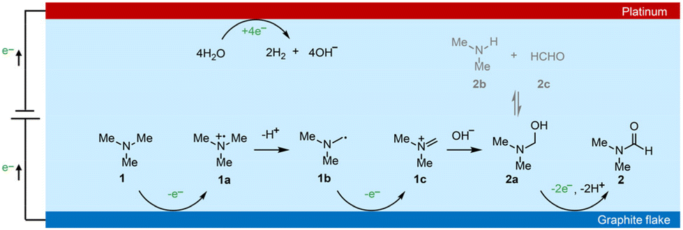 | ||
| Scheme 3 Proposed reaction mechanism of electrochemical of TMA to DMF. | ||
Continuous electrosynthesis of DMF
Considering the large demand of DMF in practical scenarios, it is important to achieve DMF electrosynthesis in a continuous fashion. Therefore, we set up a two-electrode, zero-gap membrane-electrode assembly (MEA) flow reactor with an anion exchange membrane (AEM) based on our previous experience,56 and evaluated the feasibility of continuous DMF production. By using the AEM configuration, ohmic resistance can be reduced, which is beneficial for energy efficiency especially at high current densities. The flow reactor was integrated using a graphite flake (2 cm × 2 cm) as the anode and a Pt plate (2 cm × 2 cm) as the cathode (Fig. 3a and b). Under standard reaction conditions (0.7 M K2CO3 with 20 mM TMA, flow rate of 5.4 mL min−1, Fig. S13†), without introducing TMA, the anodic current density increase is contributed by the OER process which requires a high voltage of 2.0 V. In contrast, the TMA oxidation takes place at a cell voltage of 1.6 V (Fig. 3c), suggesting that TMA oxidation is preferable to the OER, consistent with the results in the H-cell reactor. However, when the voltage increased above 2.7 V, the OER becomes preferable as shown by the higher current density, presumably due to the limitation of TMA diffusion in the flow reactor that makes TMA oxidation less competitive compared to the OER.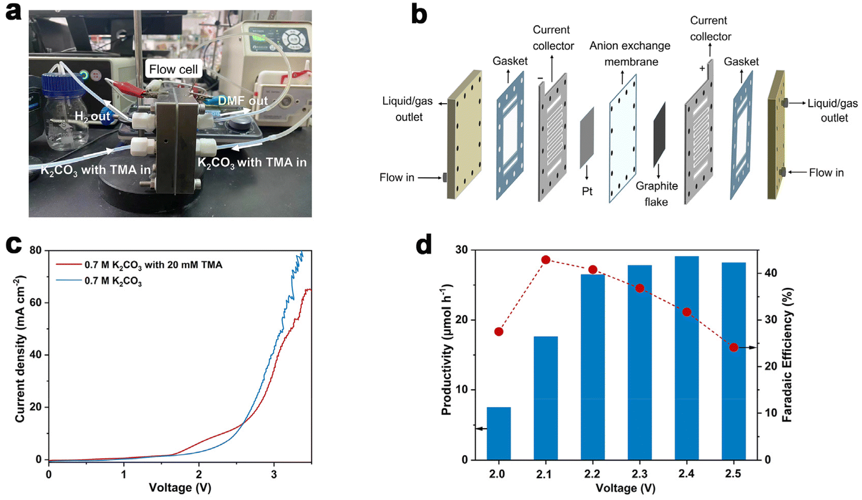 | ||
| Fig. 3 Reaction evaluation in the MEA flow reactor. (a) Photograph of the MEA flow reactor. (b) Schematic illustration of the MEA flow reactor. (c) LSV curves at a scan rate of 10 mV s−1 in 0.7 M K2CO3 with or without 20 mM TMA at a flow rate of 5.4 mL min−1. (d) Productivity and faradaic efficiency as a function of potential. Reaction conditions: 0.7 M K2CO3 with 20 mM TMA at a flow rate of 5.4 mL min−1. | ||
Similar to the results shown in the aforementioned H-cell reactor, the applied voltage is a key factor influencing DMF productivity and FE. We thus varied the applied voltage from 2.0 V to 2.5 V (Fig. 3d) in the MEA flow reactor. The results show that DMF productivity and FE are relatively low under a lower voltage, and high selectivity of formaldehyde is obtained, which is an indication of the slow oxidation of the aminal intermediate at the lower voltage (Fig. S14†). The productivity of DMF increased at increased voltages, but FE decreased due to the competition of the OER. After preliminary optimization of the applied voltage, we achieved continuous DMF electrosynthesis with a productivity of 26 μmol h−1 and FE of 40% at 2.2 V. Then a 20-hour i–t test was conducted to evaluate the stability of this MEA flow reactor-based system. Under a cell voltage of 2.1 V, the solution of 0.7 M K2CO3 with 20 mM TMA was circulated into the MEA flow reactor with a flow rate of 5.4 mL min−1. A relatively stable current density (ca. 2 mA cm−2) and FE of DMF (ca. 38%) were achieved in the 20-hour test (Fig. S15†), indicating high stability.
To further increase DMF productivity to meet more practical-relevant scenarios, a two-electrode, membrane-free flow reactor was conceived (Fig. 4a) and set up (Fig. 4b and Fig. S16†). By not using a membrane (AEM), although ohmic resistance would increase, the reactor would be more cost-effective, thus being conducive to scaling up the reactor in more practical scenarios. Due to the high cost of Pt, and also the comparable activity of Ni foam as the cathode (tested in a membrane-free flow reactor with a smaller working electrode area of 4 cm2, Fig. S17†), Ni foam was used as the cathode in the membrane-free flow reactor (8 cm × 9 cm). Compared with MEA, the membrane-free flow reactor has one feed inlet and one discharge outlet, so the resulting gas–liquid is mixed at the discharge outlet. Optimization of TMA concentration and flow rate was then performed (Fig. S18†). The DMF productivity was higher in 0.7 M K2CO3 with 200 mM TMA at a flow rate of 5.4 mL min−1. The LSV curve (Fig. S19a†) shows that TMA oxidation takes place from a cell voltage of approximately 1.9 V, and the current density reached 100 mA cm−2 at 2.5 V. The voltage is lower than that in 0.7 M K2CO3 without TMA, suggesting that TMA oxidation is preferable to the OER. This is consistent with the results in the aforementioned investigations in the H-cell and MEA flow reactors. We then demonstrated that DMF can be produced in a high yield using this membrane-free flow reactor. The electrolyte passes through the flow reactor with circulation, and the products (and the unreacted TMA) were immersed in an ice-bath to prevent TMA from evaporation considering its low boiling point (ca. 3 °C). Eventually, DMF was obtained in a high yield (75%) in a 24-hour test (Fig. 4c). Moreover, the system can be reused three times without activity loss, demonstrating the reusability of the flow system.
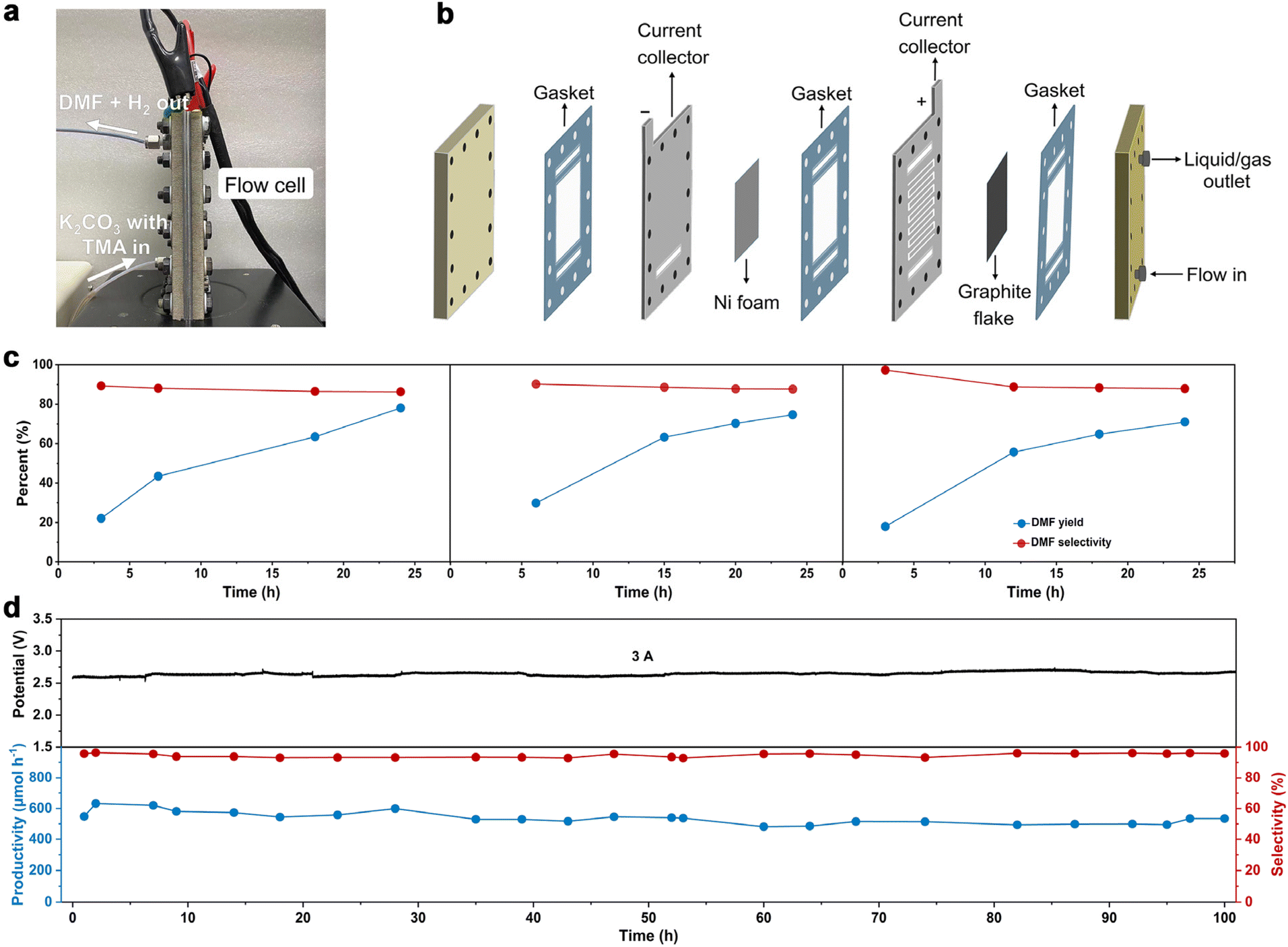 | ||
| Fig. 4 Catalytic evaluation in the membrane-free flow reactor. (a) Photograph of the membrane-free flow reactor. (b) Schematic illustration of the membrane-free flow reactor. (c) Chronopotentiometry test by circulating the electrolyte over 24-hours in consecutive three cycles. Reaction conditions: constant current at 3 A, in 0.7 M K2CO3 with 20 mM TMA at flow rate of 5.4 mL min−1. (d) Chronopotentiometry test in single-path electrolysis in the flow cell. Reaction conditions: constant current at 3 A, in 0.7 M K2CO3 with 200 mM TMA at flow rate of 5.4 mL min−1. | ||
We then evaluated the robustness of this flow system in a long-term operation, which is a prerequisite for practical applications. The device was continuously operated for 100 hours without a noticeable change in DMF selectivity (roughly 98%) or cell voltage (roughly 2.6 V). During this stability test, the formation rate of DMF was maintained relatively constant at around 550 μmol h−1 (Fig. 4d). Unfortunately, the FE of DMF was low (approximately 2%, Fig. S19b†), much lower than that obtained in the H-cell or MEA flow reactors. This is not unreasonable considering the large working area of the membrane-free reactor, on which TMA diffusion would be more difficult, which in turn results in intense OER. These results indicate that the reactor design with a large working area may become a decisive factor in determining the reaction efficiency, which is worth investigating for scaling-up electrosynthesis. Further optimizations of the MEA flow reactor and membrane-free reactor are ongoing in our laboratory.
Eventually, we assessed green chemistry metrics and profitability of electrochemical synthesis of DMF from TMA shown in this work. Regarding green chemistry characteristics, we performed calculations on several important green chemistry metrics, including the AE, E-factor, and CE. The calculation details of these green chemistry metrics are shown in the ESI (Tables S5 and S6).† The calculation results of the electrochemical synthesis of DMF display high AE (94.8%), low E-factor (4.62), and high CE (88%), indicating that the synthetic method is potentially green and sustainable. Regarding profitability, we conducted a preliminary techno-economic analysis (TEA) (full details of the TEA are available in the ESI, Fig. S20†). The results suggest that the profitability of the process depends on the cost of renewable electricity, operating current density and FE of DMF. With the development of renewable electricity in the future, its cost continues to plummet to below 10 cents kW h−1.57 In this context, the electrochemical oxidation of TMA to DMF is economically possible when the system achieves a certain FE (>30%) and current density (>100 mA cm−2). While there is still a substantial gap between the low FE we obtained and the desirable profitability requirement, continuous DMF production with a high current and long-term stability suggests the potential of the electrochemical strategy.
Conclusions
In summary, we have developed an unprecedented electrochemical oxidation strategy to directly transform TMA to DMF coupled with H2 production. This electrochemical process proceeds at room temperature and ambient pressure in 0.7 M K2CO3 with 20 mM TMA without using any mediator. DMF production with >50% FE and 80% yield was achieved in an H-cell reactor. Mechanistic studies suggested that the reaction occurs through an aminal intermediate which is further oxidized to DMF. The productivity and robustness of this electrochemical oxidation were preliminarily demonstrated in a flow fashion including in a MEA flow reactor and in a membrane-free reactor. Furthermore, green chemistry metrics calculations indicated that this method provides an atom-economical, green and environmentally benign route to produce DMF from TMA under mild conditions, which could find potential applications in the chemical industry towards renewable-electricity-powered electrosynthesis. Further studies are ongoing in our laboratory to promote the FE and selectivity of DMF and to expand the generality of this strategy towards diverse amine compounds of high value.Author contributions
H. D., B.-J. L., J. M. and A.-Z. L. conceived and designed the experiments. J. M. and A.-Z. L. contributed to the experimental optimization and analysis. J. L. helped with the setup of the flow cell system. Y. W. helped with TEA analysis. J. M. and A.-Z. L. wrote the paper. H. D. and B.-J. L. revised the manuscript. All authors commented on the final manuscript.Conflicts of interest
There are no conflicts to declare.Acknowledgements
Financial support was provided by the Beijing Natural Science Foundation (JQ22003) and the National Natural Science Foundation of China (21978147, 21935001, 22090030, 22105015). We also thank the Haihe Laboratory of Sustainable Chemical Transformations for financial support.References
- G. Bellussi, M. Bohnet, J. Bus, K. Drauz, H. Greim, K.-P. Jackel, T. Laird, U. Kars, A. Kleemann, G. Kreysa, W. Meier, E. Otto, M. Roper, J. Scholtz, K. Sundmacher, R. Ulber and U. Wietelmann, Formamides, in Ullmann's Encyclopedia of Industrial Chemistry, Wiley-VCH, Weinheim, 2011 Search PubMed.
- K. Weissermel and H.-J. Arpe, Industrial Organic Chemistry, ed. C. R. Lindley and S. Hawkins, Wiley-VCH, Weinheim, 4th edn, 2003, pp. 44–46 Search PubMed.
- S. Ding and N. Jiao, Angew. Chem., Int. Ed., 2012, 51, 9226–9237 CrossRef CAS PubMed.
- J. Muzart, Tetrahedron, 2009, 65, 8313–8323 CrossRef CAS.
- Dimethylformamide (DMF) Market by Type (Reactant and Feedstock), End-use industries (Chemicals, Electronics, Pharmaceutical, and Agrochemical), and Region (Asia Pacific, Europe, North America, Europe, MEA and South America) - Global Forecast to 2027 (Market Research Report, MarketsandMarkets, 2021). https://www.marketsandmarkets.com/Market-Reports/dimethylformamide-market-129340374.html.
- K. Othmer, Dimethylformamide, in Kirk-Othmer Encyclopedia of Chemical Technology, John Wiley & Sons, 2013 Search PubMed.
- H. A. Wittcoff, B. G. Reuben and J. S. Plotkin, Industrial Organic Chemicals, Wiley-VCH, Weinheim, 2012, pp. 448–452 Search PubMed.
- G. Bellussi, M. Bohnet, J. Bus, K. Drauz, H. Greim, K.-P. Jackel, T. Laird, U. Kars, A. Kleemann, G. Kreysa, W. Meier, E. Otto, M. Roper, J. Scholtz, K. Sundmacher, R. Ulber and U. Wietelmann, Methylamines, in Ullmann's Encyclopedia of Industrial Chemistry, Wiley-VCH, Weinheim, 2015 Search PubMed.
- K. Othmer, Methylamines, in Kirk-Othmer Encyclopedia of Chemical Technology, John Wiley & Sons, 2000 Search PubMed.
- M. Keane Jr., G. C. Sonnichsen, L. Abrams, D. R. Corbin, T. E. Gier and R. D. Shannon, Appl. Catal., 1987, 32, 361 CrossRef.
- F. Rieck Genannt Best, A. Mundstock, H. Richter, P. A. Kißling, K. D. J. Hindricks, A. Huang, P. Behrens and J. Caro, Microporous Mesoporous Mater., 2022, 337, 111920 CrossRef CAS.
- F. Rieck Genannt Best, A. Mundstock, P. A. Kißling, H. Richter, K. D. J. Hindricks, A. Huang, P. Behrens and J. Caro, Ind. Eng. Chem. Res., 2021, 61, 307–316 CrossRef.
- R. Wu, J. Han, Y. Wang, M. Chen, P. Tian, X. Zhou, J. Xu, J.-N. Zhang and W. Yan, Inorg. Chem. Front., 2022, 9, 5766–5773 RSC.
- V. R. Pattabiraman and J. W. Bode, Nature, 2011, 480, 471–479 CrossRef CAS PubMed.
- E. R. Klobukowski, M. L. Mueller, R. J. Angelici and L. K. Woo, ACS Catal., 2011, 1, 703–708 CrossRef CAS.
- J. R. Khusnutdinova, Y. Ben-David and D. Milstein, J. Am. Chem. Soc., 2014, 136, 2998–3001 CrossRef CAS PubMed.
- X. Jin, K. Kataoka, T. Yatabe, K. Yamaguchi and N. Mizuno, Angew. Chem., Int. Ed., 2016, 55, 7212–7217 CrossRef CAS PubMed.
- Y. Zhang, D. Riemer, W. Schilling, J. Kollmann and S. Das, ACS Catal., 2018, 8, 6659–6664 CrossRef CAS.
- Y. Zhang, W. Schilling, D. Riemer and S. Das, Nat. Protoc., 2020, 15, 822–839 CrossRef CAS PubMed.
- Y. Jin, L. Ou, H. Yang and H. Fu, J. Am. Chem. Soc., 2017, 139, 14237–14243 CrossRef CAS PubMed.
- S. Nakai, T. Yatabe, K. Suzuki, Y. Sasano, Y. Iwabuchi, J. Y. Hasegawa, N. Mizuno and K. Yamaguchi, Angew. Chem., Int. Ed., 2019, 58, 16651–16659 CrossRef CAS PubMed.
- M. J. P. Mandigma, J. Zurauskas, C. I. MacGregor, L. J. Edwards, A. Shahin, L. d'Heureuse, P. Yip, D. J. S. Birch, T. Gruber, J. Heilmann, M. P. John and J. P. Barham, Chem. Sci., 2022, 13, 1912–1924 RSC.
- D. P. Riley, J. Chem. Soc., Chem. Commun., 1983, 1530–1532 RSC.
- G. T. Davis and D. H. Rosenblatt, Tetrahedron Lett., 1968, 9, 4085–4086 CrossRef.
- K. Tadamitsu, Production of N,N-Dimethylformamide, JPH10158227A, 1998.
- S. Tang, Y. Liu and A. Lei, Chem, 2018, 4, 27–45 CAS.
- L. F. T. Novaes, J. Liu, Y. Shen, L. Lu, J. M. Meinhardt and S. Lin, Chem. Soc. Rev., 2021, 50, 7941–8002 RSC.
- Z.-W. Hou, D.-J. Liu, P. Xiong, X.-L. Lai, J. Song and H.-C. Xu, Angew. Chem., Int. Ed., 2021, 60, 2943–2947 CrossRef CAS PubMed.
- C.-Y. Cai, X.-L. Lai, Y. Wang, H.-H. Hu, J. Song, Y. Yang, C. Wang and H.-C. Xu, Nat. Catal., 2022, 5, 943–951 CrossRef CAS.
- R. Li, K. Xiang, Z. Peng, Y. Zou and S. Wang, Adv. Energy Mater., 2021, 11, 2102292 CrossRef CAS.
- C. Tang, Y. Zheng, M. Jaroniec and S.-Z. Qiao, Angew. Chem., Int. Ed., 2021, 60, 19572–19590 CrossRef CAS PubMed.
- Y. Wang, T. Li, Y. Yu and B. Zhang, Angew. Chem., Int. Ed., 2022, 61, e202115409 CAS.
- H. Sheng, A. N. Janes, R. D. Ross, H. Hofstetter, K. Lee, J. R. Schmidt and S. Jin, Nat. Catal., 2022, 5, 716–725 CrossRef CAS.
- A. Xu, S.-F. Hung, A. Cao, Z. Wang, N. Karmodak, J. E. Huang, Y. Yan, A. Sedighian Rasouli, A. Ozden, F.-Y. Wu, Z.-Y. Lin, H.-J. Tsai, T.-J. Lee, F. Li, M. Luo, Y. Wang, X. Wang, J. Abed, Z. Wang, D.-H. Nam, Y. C. Li, A. H. Ip, D. Sinton, C. Dong and E. H. Sargent, Nat. Catal., 2022, 5, 1081–1088 CrossRef CAS.
- H. Zhou, Y. Ren, Z. Li, M. Xu, Y. Wang, R. Ge, X. Kong, L. Zheng and H. Duan, Nat. Commun., 2021, 12, 4679 CrossRef CAS PubMed.
- H. Zhou, Z. Li, S. M. Xu, L. Lu, M. Xu, K. Ji, R. Ge, Y. Yan, L. Ma, X. Kong, L. Zheng and H. Duan, Angew. Chem., Int. Ed., 2021, 60, 8976–8982 CrossRef CAS PubMed.
- Z. Li, X. Li, H. Zhou, Y. Xu, S. M. Xu, Y. Ren, Y. Yan, J. Yang, K. Ji, L. Li, M. Xu, M. Shao, X. Kong, X. Sun and H. Duan, Nat. Commun., 2022, 13, 5009 CrossRef CAS PubMed.
- C. Xia, S. Back, S. Ringe, K. Jiang, F. Chen, X. Sun, S. Siahrostami, K. Chan and H. Wang, Nat. Catal., 2020, 3, 125–134 CrossRef CAS.
- T. Wang, Z. Huang, T. Liu, L. Tao, J. Tian, K. Gu, X. Wei, P. Zhou, L. Gan, S. Du, Y. Zou, R. Chen, Y. Li, X. Fu and S. Wang, Angew. Chem., Int. Ed., 2022, 61, e202115636 CAS.
- T. Shono, H. Hamaguchi and Y. Matsumura, J. Am. Chem. Soc., 1975, 97, 4264–4268 CrossRef CAS.
- A. M. Jones and C. E. Banks, J. Org. Chem., 2014, 10, 3056–3072 Search PubMed.
- P. W. Seavill and J. D. Wilden, Green Chem., 2020, 22, 7737–7759 RSC.
- N. R. Deprez, D. J. Clausen, J. X. Yan, F. Peng, S. Zhang, J. Kong and Y. Bai, Org. Lett., 2021, 23, 8834–8837 CrossRef CAS PubMed.
- F. Wang, M. Rafiee and S. S. Stahl, Angew. Chem., Int. Ed., 2018, 57, 6686–6690 CrossRef CAS PubMed.
- C. Li, C.-C. Zeng, L.-M. Hu, F.-L. Yang, S. J. Yoo and R. D. Little, Electrochim. Acta, 2013, 114, 560–566 CrossRef CAS.
- Y. Hao, T. Li, J. Wu, J. Wang, C. Jia, T. Liu, X. Yang, Z. Liu and M. Gong, J. Am. Chem. Soc., 2021, 143, 1493–1502 CrossRef CAS PubMed.
- H. Zhou, Z. Li, S.-M. Xu, L. Lu, M. Xu, K. Ji, R. Ge, Y. Yan, L. Ma, X. Kong, L. Zheng and H. Duan, Angew. Chem., Int. Ed., 2021, 60, 8976–8982 CrossRef CAS PubMed.
- X. Bai, Z. Liu, K. Ye, Y. Wang, X. Zhang, H. Yue, G. Tian and S. Feng, Tetrahedron Lett., 2014, 55, 319–321 CrossRef CAS.
- A. S. Shraifel’, A. F. Borodacheva, S. V. Komissarov and G. B. Sklyarova, Fibre Chem., 2014, 46, 217–221 CrossRef.
- J. R. Khusnutdinova, Y. Ben-David and D. Milstein, J. Am. Chem. Soc., 2014, 136, 2998–3001 CrossRef CAS PubMed.
- C. J. Legacy, A. Wang, B. J. O'Day and M. H. Emmert, Angew. Chem., 2015, 127, 15120–15123 CrossRef.
- J.-L. Lin, Y.-C. Lin, B.-C. Lin, P.-C. Lai, T.-E. Chien, S.-H. Li and Y.-F. Lin, J. Phys. Chem. C, 2014, 118, 20291–20297 CrossRef CAS.
- H. Zhang, P. Zhang, M. Jiang, H. Yang and H. Fu, Org. Lett., 2017, 19, 1016–1019 CrossRef CAS PubMed.
- M. Jin, L. Ma, L. Zhou, K. Ji, X. Xue, B.-J. Li and H. Duan, Sci. China: Chem., 2022, 65, 2307–2317 CrossRef CAS.
- D. Gunasekera, J. P. Mahajan, Y. Wanzi, S. Rodrigo, W. Liu, T. Tan and L. Luo, J. Am. Chem. Soc., 2022, 144, 9874–9882 CrossRef CAS PubMed.
- H. Zhou, Y. Ren, Z. Li, M. Xu, Y. Wang, R. Ge, X. Kong, L. Zheng and H. Duan, Nat. Commun., 2021, 12, 4679 CrossRef CAS PubMed.
- P. D. Luna, C. Hahn, D. Higgins, S.-A. Jaffer, T.-F. Jaramillo and E.-H. Sargent, Science, 2019, 364, 6438 CrossRef PubMed.
Footnotes |
| † Electronic supplementary information (ESI) available. See DOI: https://doi.org/10.1039/d3gc01406a |
| ‡ These authors contributed equally to this work. |
| This journal is © The Royal Society of Chemistry 2023 |