
Pre-embedding an energetic metal–organic framework to create interconnected pore structures in nitrogen-doped carbon for green and effective hydrogen peroxide electrosynthesis†
Yuyu
Guo‡
,
Jinxi
Han‡
,
Shuting
Li
,
Zhengqiang
Xia
,
Sanping
Chen
 *,
Gang
Xie
,
Shengli
Gao
and
Qi
Yang
*
*,
Gang
Xie
,
Shengli
Gao
and
Qi
Yang
*
Key Laboratory of Synthetic and Natural Functional Molecule of the Ministry of Education, College of Chemistry and Materials Science, Northwest University, Xi'an, Shaanxi 710127, China. E-mail: yangqi@nwu.edu.cn; sanpingchen@126.com
First published on 21st April 2023
Abstract
The two-electron (2e−) oxygen reduction reaction (ORR) is a green way to produce hydrogen peroxide (H2O2). However, the ORR occurs at the gas–liquid–solid interface, and the active sites in the electrocatalyst are buried, preventing them from taking part in the reaction and lowering the reaction efficiency. To boost the efficacy of the 2e− ORR, the template method is widely used to construct pores to optimize the mass transfer process; however, the post-treatment using strong acids and bases will inevitably produce toxic pollutants. Herein, an interconnected pore structure was produced in the carbon electrocatalyst by utilizing an “inside-out” energy release pore-making strategy triggered by the detonation of an energy metal–organic framework (EMOF). In order to expose additional active sites for the 2e− ORR, the pre-buried EMOF releases large amounts of gases, generates shocks to the carbon electrocatalyst during the pyrolysis process, and avoids acid–base post-treatment. The electrocatalyst demonstrated a remarkable H2O2 yield of 74.98 mg h−1 and an H2O2 selectivity of over 95%. It is worth noting that the electrocatalyst can consistently produce H2O2 for more than 42 hours with negligible performance degradation. This facile and green strategy can be applied to modify the pore structure of the electrocatalysts to achieve the desired 2e− ORR performance, thus enabling the green and efficient electrosynthesis of H2O2.
Introduction
Global public health crises, such as A(H5N1),1 highly pathogenic coronavirus2 and monkeypox,3 are becoming a challenge for human beings. A strong oxidizing agent, hydrogen peroxide (H2O2), when dissolved in water, may render many bacteria inert.4–6 The global consumption of H2O2 was 5.5 million tons in 2018 and is anticipated to increase to 6.5 million tons by 2023.7 The most popular technique for producing H2O2 on a large scale is the anthraquinone method; however, due to the large amount of hazardous waste it produces, which causes irreversible harm to the environment and humans, researchers are currently working to develop environmentally friendly H2O2 production methods.8–11 The electrochemical 2e− ORR is a facile and green method of synthesizing H2O2 without any negative byproducts.12–19 The electrolyte flow typically carries O2 to the active sites, where it is reduced to H2O2 or H2O, corresponding to the 2e− and 4e− ORR pathways, respectively.20–25 An electrocatalyst with high 2e− selectivity is highly required for the production of H2O2. Hg alloyed with other metals exhibits great selectivity and high efficiency for the 2e− ORR, but its practical use on a large scale is hampered by Hg's toxicity.26,27 Developing a non-toxic and efficient 2e− ORR electrocatalyst still remains a challenge.Carbon is one of the most extensively distributed elements on the planet; carbon materials have numerous sources and are inexpensive, non-toxic, and endowed with stable chemical properties according to their sp2 hybridization network.28–30 Recent studies have demonstrated that carbon materials modified in particular ways, such as by heteroatom doping,31,32 inducing defects,33–35 plasma treatment36,37 and functional group modification,38,39 can attain promising electrochemical ORR performance.
The question is how to improve the selectivity and efficiency of the 2e− ORR. There are numerous active sites inside the carbon materials that are unable to participate in the ORR because it occurs at the interface of gas, liquid and solid phases,40–42 significantly lowering the reaction efficiency. Constructing pore structures inside bulk materials can expose more electrochemically active sites, which can improve the efficiency of the ORR.43 The template method is the most widely used way to build pore structures inside materials. Tsuji et al. used a porous alumina template with a controllable pore size to optimize the structure of carbon nanofibers.44 The carbon nanofibers after removing the template using NaOH resulted in a more uniform deposition of Pt sites for the ORR. Wu et al. used SiO2 as a hard template to prepare an N-doped carbon base catalyst.45 After removing the SiO2 template with HF, a hierarchically macro–meso–microporous N-doped carbon structure was created. Although many electrocatalysts with good catalytic performance have been investigated by researchers using the template method, it is impossible to avoid the use of strong acids and bases for the post-treatment process of template removal. Developing a facile and green method to build pore structures inside carbon materials still remains a challenge.
Energetic metal–organic frameworks (EMOF) are a subclass of MOFs in which the organic ligands have a high energy level and their decomposition can release enormous amounts of gas and energy, known as the detonation effect.46,47 EMOF might be rationally incorporated into the carbon electrocatalyst production process to modify the inner structure of bulk materials, without requiring any dangerous chemical reagents for post-treatment, and expose more active sites. Herein, we have illustrated a facile and green “inside-out” energy release pore-making strategy to construct interconnected pores inside a carbon electrocatalyst through the detonation of EMOF. A kind of EMOF, {[Zn2(HTATT)2(H2O)2]·3H2O}n, with a nitrogen content of 58%, which was prepared by our research group, was pre-buried in a carbon aerogel. When the mixture is heated to a high temperature, EMOF breaks down and releases large amounts of heat and gas, impacting the carbon aerogel from the inside out, and finally, it forms the electrocatalyst with interconnected pores. The obtained carbon aerogel electrocatalyst exhibited high 2e− ORR selectivity and H2O2 yield.
Results and discussion
Synthesis of the electrocatalyst
Scheme 1 depicts the synthesis process of CA-NR. First, a hydrothermal technique was used to produce an EMOF-doped carbon aerogel precursor. The precursor was then crushed into powder after being freeze-dried. The powder was finally pyrolyzed in a tube furnace. The EMOF detonated during pyrolysis, releasing a large amount of energy and gas. The EMOF exhibited excellent detonation properties (Fig. S2 and Table S1†). The carbon material was impacted and affected by the energy and gas, and as a result, an electrocatalyst with an interconnecting pore structure was obtained.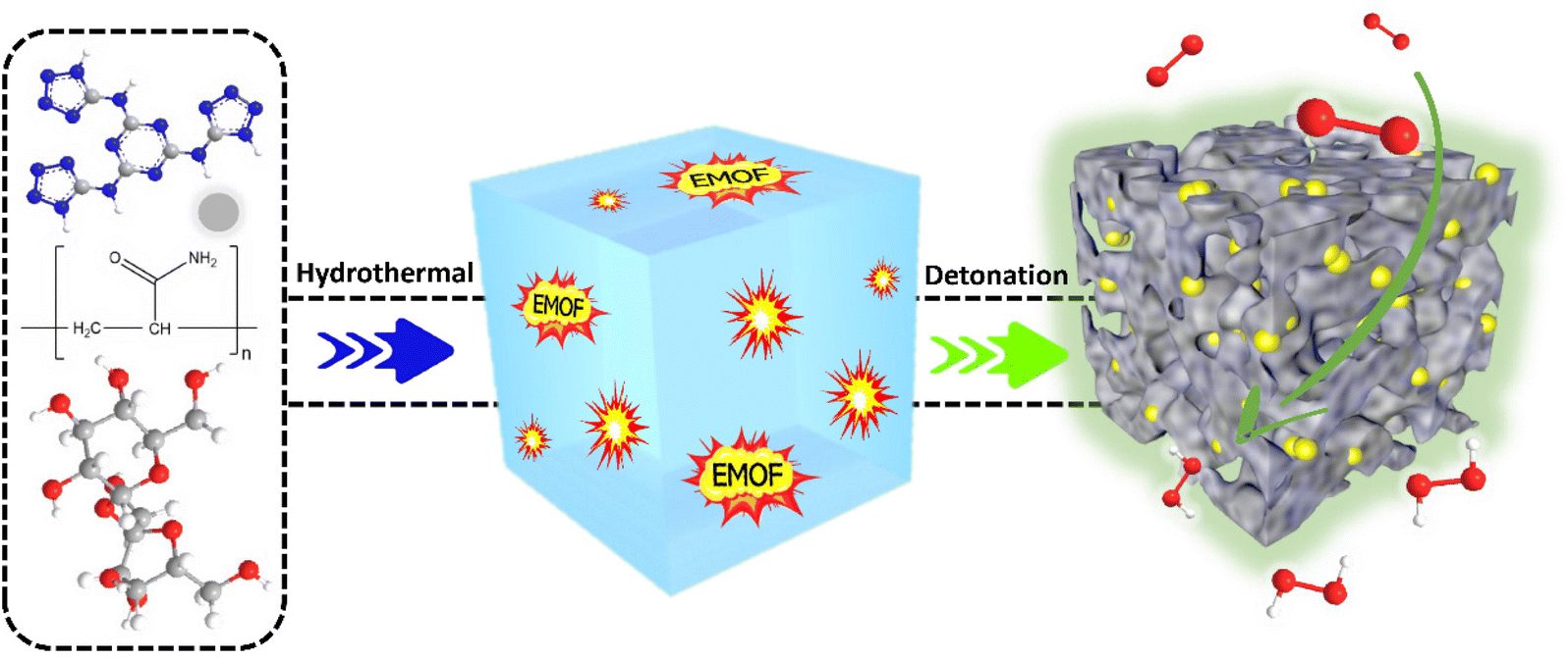 | ||
| Scheme 1 Schematic diagram for the synthesis of CA-NR. | ||
Characterization of the electrocatalyst
XRD was used to identify the phase structure of the samples (Fig. 1a). All the samples exhibited two broad diffraction peaks around 25° and 44°, which corresponded to the (002) and (100) planes of graphite,48 respectively. This suggests that during the high-temperature pyrolysis, the Zn atoms evaporated and the EMOF entirely disintegrated. The degree of graphitization was assessed using the Raman spectrum (Fig. 1b). For CA-NR, CA-ZIF8, CA-Zn, and CA, the intensity ratios of the D band (defect 1350 cm−1) to the G band (sp2 hybridization of carbon 1580 cm−1) were 1.36, 1.02, 1.02, and 1.01, respectively. The similar low ID/IG values indicate that the Zn ions and ZIF8 (low nitrogen content ∼24.4%) have only minor effects on the carbon matrix structure. The ID/IG value of CA-NR was 1.36, which was much higher than that of other samples, demonstrating that the detonation impact of the EMOF caused a large increase in the number of flaws in the carbon matrix. The active sites for electrocatalysis can be made up of many defect sites.49 The adsorption–desorption isotherm of samples made by pre-embedding various precursors (EMOF for CA-NR, ZIF8 for CA-ZIF8, Zn2+ for CA-Zn, and none for CA) is shown in Fig. 1c. Each curve belongs to an H3 hysteresis loop and type I isotherm. There are numerous structures in the samples since the adsorption capacity increases sharply at a low relative pressure (P/P0 < 0.05) but not at a high relative pressure, where there is no clear saturated adsorption platform. As a result, the specific surface areas of CA, CA-NR, CA-ZIF8, CA-Zn, and CA are 761.32 m2 g−1, 605.56 m2 g−1, 597.61 m2 g−1, and 504.7 9 m2 g−1, respectively. After doping the EMOF, the specific surface area of CA-NR significantly increases, which is almost 1.5 times that of CA. More active sites can be exposed by a sample with a larger specific surface area, which improves the sample's electrocatalytic performance.50 The pore size distribution is exhibited in Fig. 1d, with the pore size distribution of CA mainly concentrated on the mesoporous regions. The pore size distributions of CA-Zn and CA-ZIF8 are broader than that of CA after doping with Zn2+ and ZIF8, which is primarily related to the evaporation of Zn. More importantly, the pore size distribution of the sample embedded in the EMOF becomes significantly wider, which is caused by the detonation effect of EMOF. The abundant pore structure is conducive to the electrolyte flow inside the electrocatalyst to transport more O2 to the active sites, which is beneficial for boosting the efficiency of the ORR.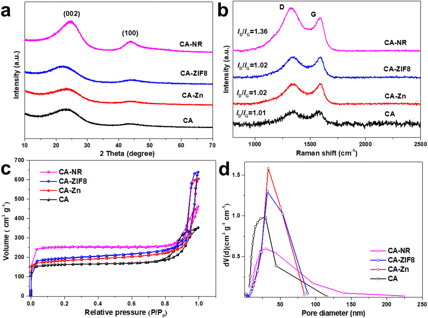 | ||
| Fig. 1 (a) XRD pattern of the samples. (b) Raman spectra of the samples. (c) N2 adsorption–desorption isotherms of the samples. (d) Pore size distribution of the samples. | ||
The morphology of the samples was detected by SEM and TEM. Fig. 2a demonstrates that the pure carbon aerogel (CA) is aggregated by small carbon spheres and the pore structure exists between the stacked spheres (Fig. 2e and i). It can be seen that both samples (CA-Zn and CA-ZIF8) exhibit comparable macroporous structures in Fig. 2b and c. It can be inferred that the evaporation of Zn is primarily responsible for the macroporous formations.51Fig. 2d displays the SEM images of CA-NR, where an interconnected pore structure is visible. Due to the detonation effect of EMOF, when the pyrolysis temperature exceeds the decomposition temperature, the EMOF decomposes and releases enormous amounts of energy and gases, causing shock and damage to the inside of the carbon aerogel. Subsequently, the carbon spheres melt and fuse, rather than remaining in their natural state. The interconnected pore structure evolves concurrently under the influence of gases.
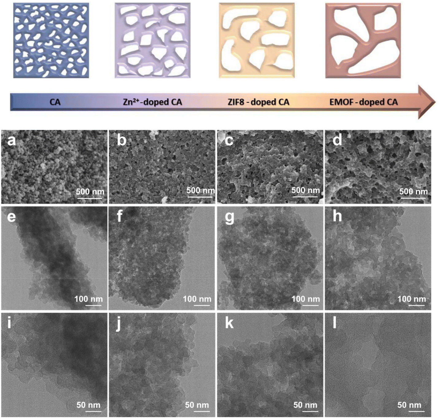 | ||
| Fig. 2 (a–d) SEM images of CA, CA-Zn, CA-ZIF8 and CA-NR. (e–h) TEM images of CA, CA-Zn, CA-ZIF8 and CA-NR. (i–l) HRTEM images of CA, CA-Zn, CA-ZIF8 and CA-NR. | ||
The EMOF can break down and release a significant amount of energy when heated to a high temperature. To examine the thermal decomposition behavior of EMOF, thermogravimetric (TG) and differential scanning calorimetry (DSC) techniques were employed (Fig. S3†). At around 100 °C, the first stage of weightlessness sets in due to the loss of free H2O molecules. The EMOF structure is still intact as shown by the subsequent continuous stable stage. As the temperature increases, the second stage of weightlessness appears at 339 °C. This is brought on by the collapse of the EMOF structure, and the DSC curve clearly shows that this is an exothermic reaction. The investigation of heat behavior supports earlier hypotheses concerning the creation of the pore structure and morphology. Interconnected pore structures and evenly distributed C, N, and O were observed in the materials by high-angle annular dark-field scanning transmission electron microscopy (HAADF-STEM) and related energy dispersive X-ray spectroscopy (EDX) techniques (Fig. 3).
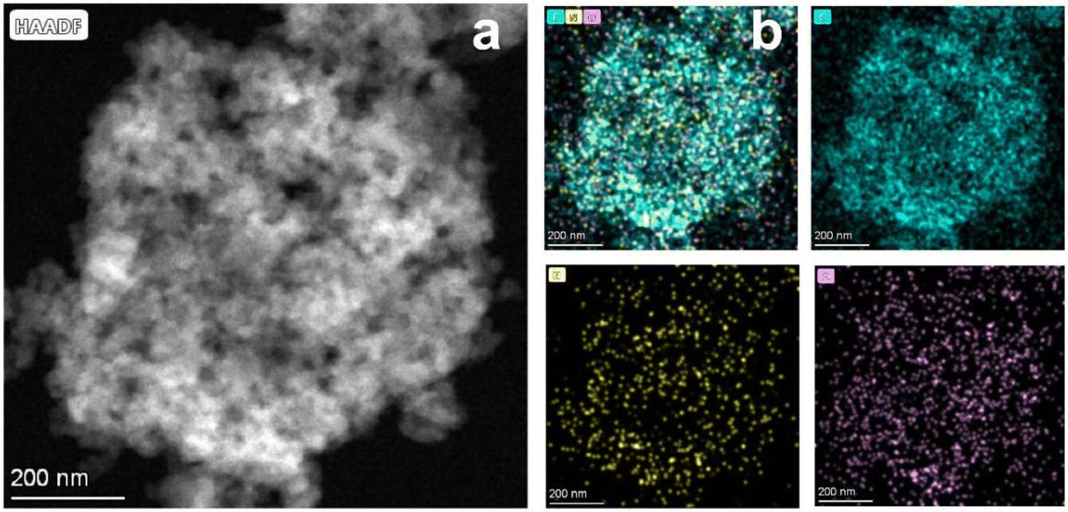 | ||
| Fig. 3 (a) HAADF-STEM image of CA-NR. (b) Elemental mapping images of CA-NR. | ||
The ORR occurs at the gas–liquid–electrocatalyst interface. O2 is dissolved in the water and then transported to the catalytic active sites by the electrolyte, and reduction takes place in the form of H2O/H2O2 for desorption. Therefore, the surface wettability of the electrocatalyst is essential to the ORR process. Fig. 4a–d depict the results of the contact angle test. The interconnected pore structure of CA-NR results in a superhydrophobic surface with a contact angle of up to 151.4°. This assists in optimizing the reaction pathway and the desorption of ORR intermediates. The contact angles of CA, CA-Zn and CA-ZIF are 120.9°, 128.5°, and 142.9°, respectively. These results indicate that doping nitrogen-rich MOF, ZIF8 and Zn2+ into carbon materials will cause the doped components to collapse and shock the bulk carbon aerogel during the co-pyrolysis process. The increased hydrophobicity promotes the ORR process and prevents the burial of active sites brought on by the flooding effect.52,53
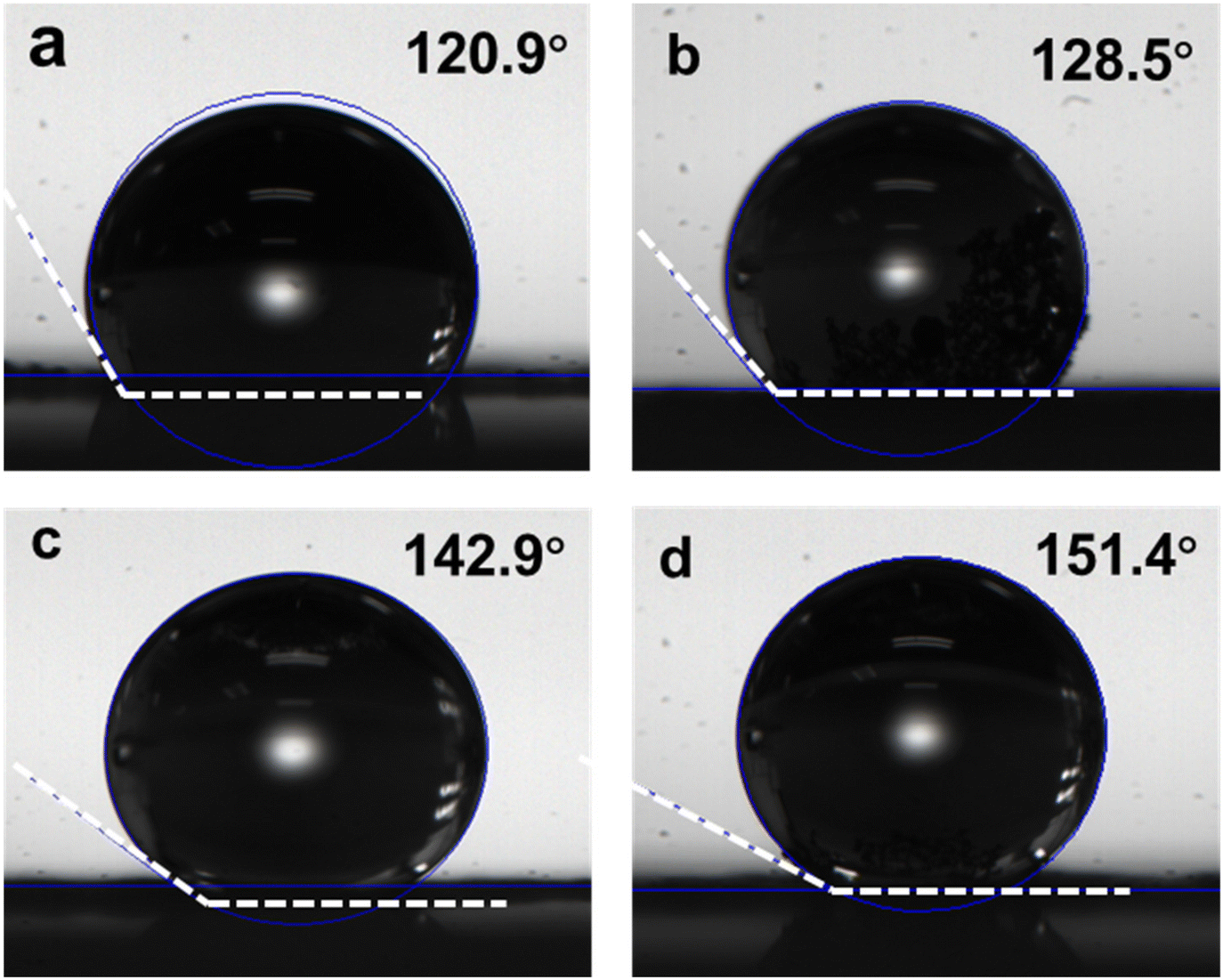 | ||
| Fig. 4 Contact angles of (a) CA, (b) CA-Zn, (c) CA-ZIF8, and (d) CA-NR. | ||
The surface chemical state of the samples was examined using XPS. The survey spectrum in Fig. 5a reveals that the samples are made up of the elements C, N and O. In the C 1s spectrum (Fig. 5b), the peaks are deconvoluted into the peaks from C![[double bond, length as m-dash]](https://www.rsc.org/images/entities/char_e001.gif) O (288.5 eV), C–O (286.1 eV) and C–C/CC (284.8 eV), respectively. Fig. 5c shows the N 1s spectrum of samples,54 where the content of pyrrolic N (400.28 eV) of CA-NR is 8.8%, compared to 8.3% for CA-ZIF8, 5.9% for CA-Zn, and 5.1% for CA. The detonation impact of the nitrogen-rich MOF destroyed the stable sp2 hybrid carbon framework, making it easier to dope N into the framework. According to previous studies, it has been suggested that the pyrrolic N sites can enhance the 2e− ORR selectivity, leading to increased efficiency of H2O2 production.55,56Fig. 5e shows the O 1s spectrum of samples, and the peaks exhibited at 533.93 eV and 532.46 eV were attributed to C–O and CO, respectively. The concentrations of O types were found to be similar in CA-NR, CA-Zn and CAZIF8. Additionally, the surface CO group was shown to enhance the 2e− ORR pathway.57,58
O (288.5 eV), C–O (286.1 eV) and C–C/CC (284.8 eV), respectively. Fig. 5c shows the N 1s spectrum of samples,54 where the content of pyrrolic N (400.28 eV) of CA-NR is 8.8%, compared to 8.3% for CA-ZIF8, 5.9% for CA-Zn, and 5.1% for CA. The detonation impact of the nitrogen-rich MOF destroyed the stable sp2 hybrid carbon framework, making it easier to dope N into the framework. According to previous studies, it has been suggested that the pyrrolic N sites can enhance the 2e− ORR selectivity, leading to increased efficiency of H2O2 production.55,56Fig. 5e shows the O 1s spectrum of samples, and the peaks exhibited at 533.93 eV and 532.46 eV were attributed to C–O and CO, respectively. The concentrations of O types were found to be similar in CA-NR, CA-Zn and CAZIF8. Additionally, the surface CO group was shown to enhance the 2e− ORR pathway.57,58
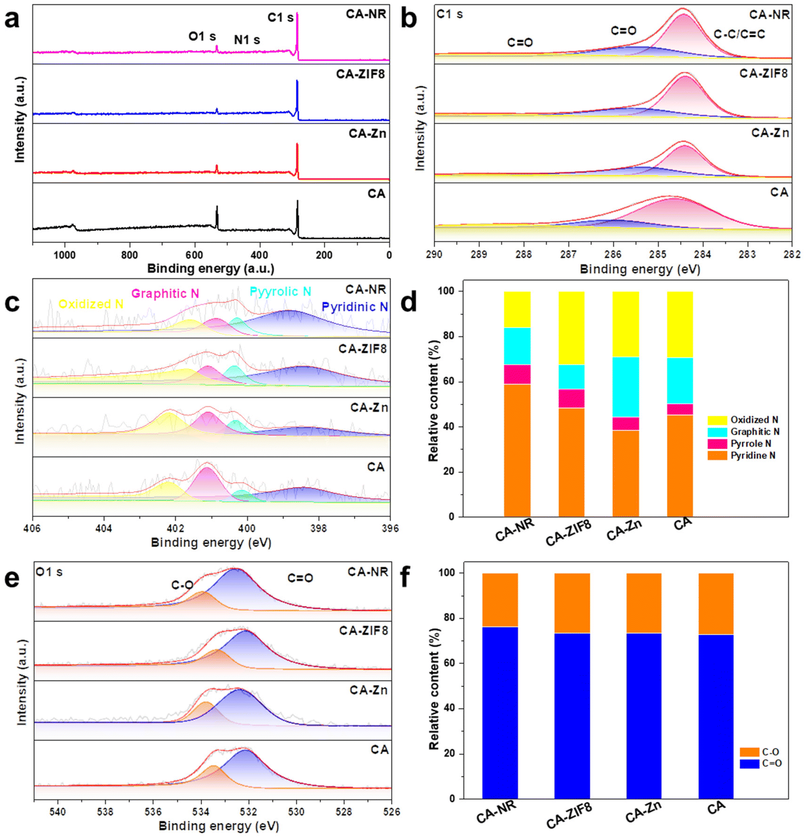 | ||
| Fig. 5 (a) Survey XPS spectrum of samples. (b) C 1s XPS spectrum of samples. (c) N 1s XPS spectrum of samples. (d) The relative content of N types. (e) O 1s XPS spectrum of samples. (f) The relative content of O types. | ||
Electrocatalytic performance of CA-NR
The ORR performance was investigated using a three-electrode rotating ring-disk system. Cyclic voltammetry (CV) was carried out under O2-saturated 0.1 M KOH. All of the carbon-based electrocatalysts showed an obvious O2 reduction peak, and CA-NR showed the most positive peak position (Fig. 6a), indicating that CA-NR exhibited excellent ORR activity. Linear sweep voltammetry (LSV) was conducted to obtain the detailed ORR performance (Fig. 6b). The ring current of CA-NR was higher than that of CA-ZIF8, CA-Zn and CA, indicating that CA-NR had a better 2e− ORR selectivity and that the ring electrode detected more H2O2 generation. The calculated H2O2 selectivity is shown in Fig. 6c. The H2O2 selectivity is higher than 70%, reaching its highest value of 93.4% at 0.65 V. Fig. 6d shows the corresponding electron transfer numbers of samples. CA-NR exhibits an electron transfer number of nearly 2 in a wide potential range (0.2–0.7 V vs. RHE), which indicates the 4e− ORR pathway was significantly suppressed. We infer that such excellent ORR performance can be attributed to the following points: (I) the pyrrolic N sites and CO functional group created by the detonation effect of nitrogen-rich MOF could be used as the active sites for the 2e− ORR, and (II) the interconnected pore structure facilitates electrolyte flow in the interior of the electrocatalyst, exposing O2 to more active sites.
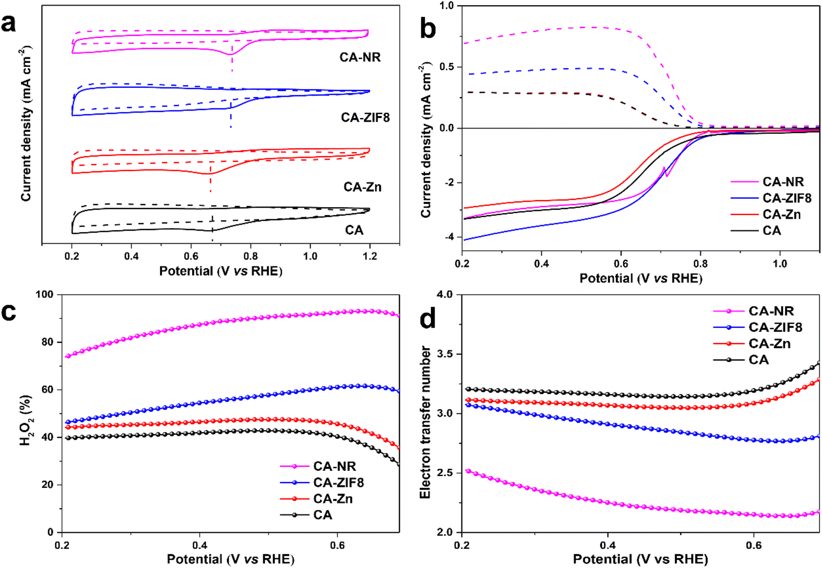 | ||
| Fig. 6 (a) Cyclic voltammograms of samples in O2-saturated 0.1 M KOH at 10 mV s−1. (b) Polarization curves of samples at 1600 rpm in O2-saturated 0.1 M KOH (dashed lines: ring current; solid lines: disk current). (c) H2O2 selectivity of samples. (d) Electron transfer number of samples. | ||
The electrochemical active surface area (ECSA) of the samples was examined by double-layer capacitance (Cdl) in the non-Faraday range to confirm whether CA-NR exposed more active sites (Fig. S4 and S5†). CA-NR exhibited a higher Cdl value (4.6 mF) and ECSA value (115 mF cm−2) than CA-ZIF8 (3.8 mF and 95 mF cm−2), CA-Zn (2.7 mF and 67.5 mF cm−2) and CA (2.0 mF and 50 mF cm−2). The results further confirmed that CA-NR exposed more active sites to improve its ORR properties.
Electrocatalytic stability of CA-NR
The RRDE setup was used at 0.65 V vs. RHE and 1600 rpm to assess the stability of the CA-NR (Fig. 7). After 8 hours, the faradaic efficiency of H2O2 for CA-NR could be maintained at above 95% during the long-term test. To further investigate the stability of CA-NR, the electrocatalyst after the long-term test was characterized by XRD, Raman spectroscopy, SEM and TEM. According to the XRD result (Fig. S6a†), the CA-NR maintains the graphite phase, with the peaks at 25° and 44° corresponding to the (002) and (100) planes of graphite, respectively. As shown in the Raman spectrum in Fig. S6b,† the ratio of ID/IG was 1.29. The slight decrease was attributed to the hostile electrochemical environment, which increased the concentration of disordered carbon and caused carbon to dissolve. The morphology of CA-NR was observed by SEM and TEM after testing (Fig. S7a–c†). The interconnected pore structure of CA-NR was found to be well-preserved, and no discernible collapse was observed. The C, N and O elements were evenly distributed in the material according to the HAADS-STEM characterization (Fig. S7d†). The long-term test showed that the EMOF detonation effect-constructed CA-NR exhibited excellent ORR stability.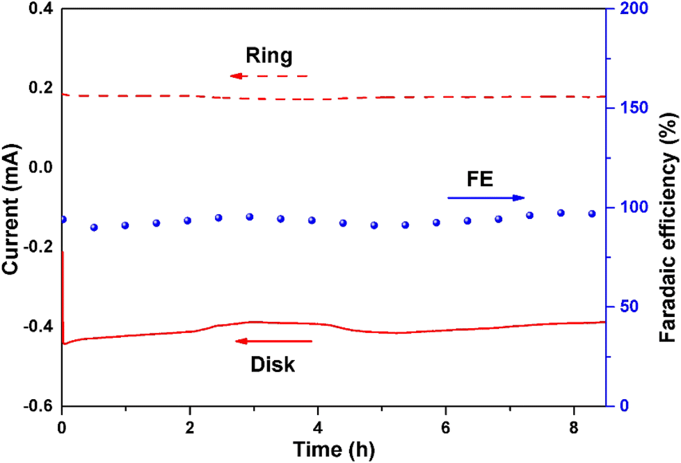 | ||
| Fig. 7 Chronoamperometry stability test of CA-NR on RRDE at 1600 rpm (0.65 V vs. RHE in 0.1 M KOH). | ||
Bulk H2O2 production
Bulk H2O2 production was conducted using an H-type electrocatalysis cell (Fig. 8). CA-NR exhibited a high FE of 95% during a 42-hour test, and the corresponding H2O2 production was 74.98 mg h−1, which was better than those of many recently reported 2e− ORR electrocatalysts (Fig. S8 and S9†). The electrocatalyst demonstrated great stability, maintaining a 3.8 mA current for 42 hours with negligible current attenuation.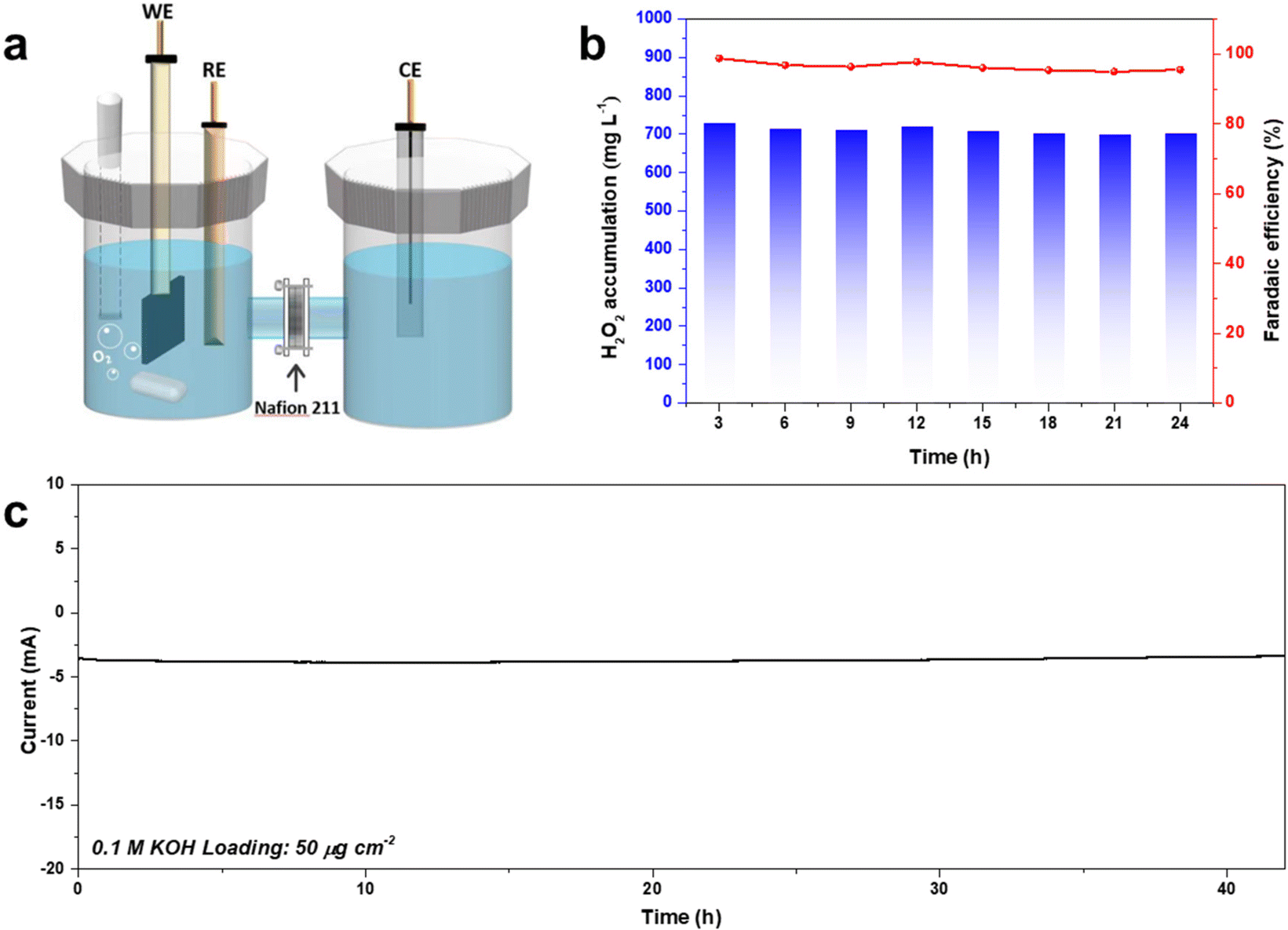 | ||
| Fig. 8 (a) Schematic of the bulk H2O2 production device. (b) The FE% and concentration of the produced H2O2 using CA-NR. (c) Long-term stability test of CA-NR at 0.65 V. | ||
Conclusion
In summary, an electrocatalyst, CA-NR, which has an interconnected pore structure, was obtained through the co-pyrolysis of carbon aerogel and EMOF. The preparation of electrocatalytic materials does not contain hazardous chemicals that require post-treatment. The formation of the unique pore structure was attributed to the detonation effect of EMOF. The CA-NR possesses excellent H2O2 selectivity with over 95% and a high yield of 74.98 mg h−1. We described a new, facile, and green strategy for constructing pore structures in order to optimize the mass transfer process and expose ORR active sites.Author contributions
Y. Y. G. and J. X. H. contributed equally to the conceptualization, data curation, formal analysis, investigation, methodology and writing – original draft. S. T. L. contributed to the investigation and methodology. Z. Q. X. contributed to the resources. S. P. C. contributed to the funding acquisition and supervision. G. X. contributed to the funding acquisition and supervision. S. L. G. contributed to the funding acquisition and supervision. Q. Y. contributed to the conceptualization, supervision, funding acquisition and writing – review & editing.Conflicts of interest
There are no conflicts to declare.Acknowledgements
The authors acknowledge the financial support from the National Natural Science Foundation of China (No. 22173072, 21973074, 22273073), Innovation Capability Support Program of Shaanxi Province (No. 2022TD-32) and Joint Fund Project-Enterprise-Shaanxi Coal Joint Fund Project (2021JLM-38).References
- M. Imai, T. Watanabe, M. Hatta, S. C. Das, M. Ozawa, K. Shinya, G. Zhong, A. Hanson, H. Katsura, S. Watanabe, C. Li, E. Kawakami, S. Yamada, M. Kiso, Y. Suzuki, E. A. Maher, G. Neumann and Y. Kawaoka, Nature, 2012, 486, 420–428 CrossRef CAS.
- A. Lal, N. A. Erondu, D. L. Heymann, G. Gitahi and R. Yates, Lancet, 2021, 397, 61–67 CrossRef CAS.
- J. Isidro, V. Borges, M. Pinto, D. Sobral, J. D. Santos, A. Nunes, V. Mixao, R. Ferreira, D. Santos, S. Duarte, L. Vieira, M. J. Borrego, S. Nuncio, I. L. de Carvalho, A. Pelerito, R. Cordeiro and J. P. Gomes, Nat. Med., 2022, 28, 1569–1572 CrossRef CAS.
- F. X. Tian, W. K. Ye, B. Xu, X. J. Hu, S. X. Ma, F. Lai, Y. Q. Gao, H. B. Xing, W. H. Xia and B. Wang, Chem. Eng. J., 2020, 398, 125570 CrossRef CAS PubMed.
- L. D. Henao, A. Turolla and M. Antonelli, Chemosphere, 2018, 213, 25–40 CrossRef.
- M. Tong, F. Liu, Q. Dong, Z. Ma and W. Liu, J. Hazard. Mater., 2020, 385, 121604 CrossRef CAS.
- K. Jiang, J. Zhao and H. Wang, Adv. Funct. Mater., 2020, 30, 2003321 CrossRef CAS.
- Y. Sun, L. Han and P. Strasser, Chem. Soc. Rev., 2020, 49, 6605–6631 RSC.
- W. Zhou, X. Meng, J. Gao and A. N. Alshawabkeh, Chemosphere, 2019, 225, 588–607 CrossRef CAS PubMed.
- S. C. Perry, D. Pangotra, L. Vieira, L. I. Csepei, V. Sieber, L. Wang, C. P. de Leon and F. C. Walsh, Nat. Rev. Chem., 2019, 3, 442–458 CrossRef CAS.
- H. Wang, C. Yang, F. Chen, G. Zheng and Q. Han, Angew. Chem., Int. Ed., 2022, 61, e202202328 CAS.
- Z. Zhou, Y. Kong, H. Tan, Q. Huang, C. Wang, Z. Pei, H. Wang, Y. Liu, Y. Wang, S. Li, X. Liao, W. Yan and S. Zhao, Adv. Mater., 2022, 34, 2106541 CrossRef CAS.
- J. Wu, M. Hou, Z. Chen, W. Hao, X. Pan, H. Yang, W. Cen, Y. Liu, H. Huang, P. W. Menezes and Z. Kang, Adv. Mater., 2022, 34, 2202995 CrossRef CAS PubMed.
- Y. Liu, J. Zhang, X. Lu, G. R. Zhang, K. Qi, Y. Bai and W. Qi, Chem. Eng. J., 2022, 444, 136665 CrossRef CAS.
- K. Lee, J. Lim, M. J. Lee, K. Ryu, H. Lee, J. Y. Kim, H. Ju, H. S. Cho, B. H. Kim, M. C. Hatzell, J. Kang and S. W. Lee, Energy Environ. Sci., 2022, 15, 2858–2866 RSC.
- W. Liu, C. Zhang, J. Zhang, X. Huang, M. Song, J. Li, F. He, H. Yang, J. Zhang and D. Wang, Appl. Catal., B, 2022, 310, 121312 CrossRef CAS.
- R. D. Ross, H. Sheng, Y. Ding, A. N. Janes, D. Feng, J. R. Schmidt, C. U. Segre and S. Jin, J. Am. Chem. Soc., 2022, 144, 15845–15854 CrossRef CAS PubMed.
- X. Huang, P. Oleynikov, H. He, A. Mayoral, L. Mu, F. Lin and Y. B. Zhang, Nano Res., 2022, 15, 145–152 CrossRef CAS PubMed.
- M. Liu, Y. Li, Z. Qi, H. Su, W. Cheng, W. Zhou, H. Zhang, X. Sun, X. Zhang, Y. Xu, Y. Jiang, Q. Liu and S. Wei, J. Phys. Chem. Lett., 2021, 12, 8706–8712 CrossRef CAS PubMed.
- M. L. Pegis, C. F. Wise, D. J. Martin and J. M. Mayer, Chem. Rev., 2018, 118, 2340–2391 CrossRef CAS PubMed.
- J. Quilez-Bermejo, E. Morallon and D. Cazorla-Amoros, Carbon, 2020, 165, 434–454 CrossRef CAS.
- D. Zhao, Z. Zhuang, X. Cao, C. Zhang, Q. Peng, C. Chen and Y. Li, Chem. Soc. Rev., 2020, 49, 2215–2264 RSC.
- J. J. Li, Y. M. Zhang, X. H. Zhang, J. Z. Huang, J. C. Han, Z. H. Zhang, X. J. Han, P. Xu and B. Song, ACS Appl. Mater. Interfaces, 2017, 9, 398–405 CrossRef CAS PubMed.
- P. Zhou, J. Lv, X. Huang, Y. Lu and G. Wang, Coord. Chem. Rev., 2023, 478, 214969 CrossRef CAS.
- B. Zhang, G. An, J. Chen, H. Guo and L. Wang, J. Colloid Interface Sci., 2023, 637, 173–181 CrossRef CAS PubMed.
- B. D. Adams, C. K. Ostrom and A. Chen, J. Electrochem. Soc., 2011, 158, B434–B439 CrossRef CAS.
- S. Siahrostami, A. Verdaguer-Casadevall, M. Karamad, D. Deiana, P. Malacrida, B. Wickman, M. Escudero-Escribano, E. A. Paoli, R. Frydendal, T. W. Hansen, I. Chorkendorff, I. E. L. Stephens and J. Rossmeisl, Nat. Mater., 2013, 12, 1137–1143 CrossRef CAS.
- M. Tahir, L. Pan, F. Idrees, X. Zhang, L. Wang, J. J. Zou and Z. L. Wang, Nano Energy, 2017, 37, 136–157 CrossRef CAS.
- H. Wang, T. Maiyalagan and X. Wang, ACS Catal., 2012, 2, 781–794 CrossRef CAS.
- B. B. Chen, M. L. Liu and C. Z. Huang, Green Chem., 2020, 22, 4034–4054 RSC.
- D. Guo, R. Shibuya, C. Akiba, S. Saji, T. Kondo and J. Nakamura, Science, 2016, 351, 361–365 CrossRef CAS PubMed.
- Z. S. Wu, S. Yang, Y. Sun, K. Parvez, X. Feng and K. Muellen, J. Am. Chem. Soc., 2012, 134, 9082–9085 CrossRef CAS PubMed.
- W. Wang, L. Shang, G. Chang, C. Yan, R. Shi, Y. Zhao, G. I. N. Waterhouse, D. Yang and T. Zhang, Adv. Mater., 2019, 31, 1808276 CrossRef PubMed.
- J. Zhu, Y. Huang, W. Mei, C. Zhao, C. Zhang, J. Zhang, I. S. Amiinu and S. Mu, Angew. Chem., Int. Ed., 2019, 58, 3859–3864 CrossRef CAS.
- D. Tang, G. Lu, Z. Shen, Y. Hu, L. Yao, B. Li, G. Zhao, B. Peng and X. Huang, J. Energy Chem., 2023, 77, 80–118 CrossRef CAS.
- Z. Wang, Q. K. Li, C. Zhang, Z. Cheng, W. Chen, E. A. McHugh, R. A. Carter, B. I. Yakobson and J. M. Tour, ACS Catal., 2021, 11, 2454–2459 CrossRef CAS.
- Z. Liu, Z. Zhao, Y. Wang, S. Dou, D. Yan, D. Liu, Z. Xia and S. Wang, Adv. Mater., 2017, 29, 1606207 CrossRef PubMed.
- T. Sun, B. D. A. Levin, J. J. L. Guzman, A. Enders, D. A. Muller, L. T. Angenent and J. Lehmann, Nat. Commun., 2017, 8, 14873 CrossRef CAS PubMed.
- X. Yang, Y. Wan, Y. Zheng, F. He, Z. Yu, J. Huang, H. Wang, Y. S. Ok, Y. Jiang and B. Gao, Chem. Eng. J., 2019, 366, 608–621 CrossRef CAS PubMed.
- X. F. Lu, B. Y. Xia, S. Q. Zang and X. W. Lou, Angew. Chem., Int. Ed., 2020, 59, 4634–4650 CrossRef CAS.
- N. Wang, S. Ma, P. Zuo, J. Duan and B. Hou, Adv. Sci., 2021, 8, 2100076 CrossRef CAS PubMed.
- J. Cui, Q. Chen, X. Li and S. Zhang, Green Chem., 2021, 23, 6898–6925 RSC.
- Y. Z. Hu, J. J. Zhang, T. Shen, Z. R. Li, K. Chen, Y. Lu, J. Zhang and D. L. Wang, ACS Appl. Mater. Interfaces, 2021, 13, 29551–29557 CrossRef CAS.
- E. Tsuji, T. Yamasaki, Y. Aoki, S. G. Park, K. Shimizu and H. Habazaki, Carbon, 2015, 87, 1–9 CrossRef CAS.
- M. Zhu, C. Zhao, X. Liu, X. Wang, F. Zhou, J. Wang, Y. Hu, Y. Zhao, T. Yao, L. M. Yang and Y. Wu, ACS Catal., 2021, 11, 3923–3929 CrossRef CAS.
- S. Li, Y. Wang, C. Qi, X. Zhao, J. Zhang, S. Zhang and S. Pang, Angew. Chem., Int. Ed., 2013, 52, 14031–14035 CrossRef CAS PubMed.
- S. Zhang, Q. Yang, X. Y. Liu, X. N. Qu, Q. Wei, G. Xie, S. P. Chen and S. L. Gao, Coord. Chem. Rev., 2016, 307, 292–312 CrossRef CAS.
- W. Ju, A. Bagger, G. P. Hao, A. S. Varela, I. Sinev, V. Bon, B. R. Cuenya, S. Kaskel, J. Rossmeisl and P. Strasser, Nat. Commun., 2017, 8, 944 CrossRef PubMed.
- C. C. Hou, L. Zou, L. Sun, K. Zhang, Z. Liu, Y. Li, C. Li, R. Zou, J. Yu and Q. Xu, Angew. Chem., Int. Ed., 2020, 59, 7384–7389 CrossRef CAS PubMed.
- R. Zhao, Z. Liang, S. Gao, C. Yang, B. Zhu, J. Zhao, C. Qu, R. Zou and Q. Xu, Angew. Chem., Int. Ed., 2019, 58, 1975–1979 CrossRef CAS PubMed.
- P. Song, M. Luo, X. Liu, W. Xing, W. Xu, Z. Jiang and L. Gu, Adv. Funct. Mater., 2017, 27, 1700802 CrossRef.
- Q. Zheng, Y. Xiong, K. Tang, M. Wu, H. Hu, T. Zhou, Y. Wu, Z. Cao, J. Sun, X. Yu and C. Wu, Nano Energy, 2022, 92, 106750 CrossRef CAS.
- Q. Zhao, J. K. An, S. Wang, Y. J. Qiao, C. M. Liao, C. Wang, X. Wang and N. Li, ACS Appl. Mater. Interfaces, 2019, 11, 35410–35419 CrossRef CAS PubMed.
- Z. H. Sheng, L. Shao, J. J. Chen, W. J. Bao, F. B. Wang and X. H. Xia, ACS Nano, 2011, 5, 4350–4358 CrossRef CAS PubMed.
- L. Li, C. Tang, Y. Zheng, B. Xia, X. Zhou, H. Xu and S. Z. Qiao, Adv. Energy Mater., 2020, 10, 2000789 CrossRef CAS.
- S. Chen, T. Luo, X. Li, K. Chen, J. Fu, K. Liu, C. Cai, Q. Wang, H. Li, Y. Chen, C. Ma, L. Zhu, Y. R. Lu, T. S. Chan, M. Zhu, E. Cortes and M. Liu, J. Am. Chem. Soc., 2022, 144, 14505–14516 CrossRef CAS PubMed.
- J. S. Lim, J. H. Kim, J. Woo, D. S. Baek, K. Ihm, T. J. Shin, Y. J. Sa and S. H. Joo, Chem, 2021, 7, 3114–3130 CAS.
- Y. Wang, Y. Zhou, Y. Feng and X. Y. Yu, Adv. Funct. Mater., 2022, 32, 2110734 CrossRef CAS.
Footnotes |
| † Electronic supplementary information (ESI) available. See DOI: https://doi.org/10.1039/d3gc00580a |
| ‡ These authors have equal contribution to this work. |
| This journal is © The Royal Society of Chemistry 2023 |