Synthesis of methanol by hydrogenolysis of biobased methyl formate using highly stable and active Cu-spinel catalysts in slurry and gas phase reactions†
Vera
Haagen
a,
Jakob
Iser
a,
Markus
Schörner
a,
Dennis
Weber
b,
Tanja
Franken
 b,
Peter
Wasserscheid
ab and
Patrick
Schühle
 *b
*b
aForschungszentrum Jülich, Helmholtz Institute for Renewable Energy Erlangen-Nürnberg, Cauerstraße 1, 91058 Erlangen, Germany
bFriedrich-Alexander-Universität Erlangen-Nürnberg (FAU), Institute of Chemical Reaction Engineering, Egerlandstraße 3, 91058 Erlangen, Germany. E-mail: patrick.schuehle@fau.de
First published on 14th February 2023
Abstract
This contribution deals with a new atom efficient two-stage production route for green methanol (MeOH) from biomass that includes biomass conversion to methyl formate (MF)/formic acid (FA) mixtures followed by hydrogenolysis to MeOH. Herein, we focus on the hydrogenolysis step and propose a materials solution to the problem of catalyst corrosion by the acidic MF/FA mixture formed in the previous biomass oxidation step. We show that Cu0.9Al2O4 spinel materials are very effective hydrogenolysis catalysts for the conversion of MA/FA mixtures to MeOH. Compared to commercial catalysts such as CuO/Cr2O3, the spinel material does not contain hazardous chromium compounds or require them during synthesis. Furthermore, this spinel catalyst shows much lower corrosion than known commercial hydrogenolysis catalysts. By using reactive frontal chromatography, nitrogen sorption, IR-ATR and XRD measurements, we show that CuO/MgO/ZnO/Al2O3 and CuO/Cr2O3 suffer from leaching of copper and chromium in the presence of FA due to the formation of mobile metal formate species. In contrast, the strongly fixed nature of copper in the highly ordered crystal structure of our Cu0.9Al2O4 spinel type catalyst leads to exceptional stability in the presence of FA and in continuous hydrogenolysis experiments for more than 110 h time-on-stream.
Introduction
Methanol (MeOH) is one of the most important platform chemicals with an annual production capacity of more than 150 million metric tons in 2020.1 It is used for the production of many different bulk chemicals, such as e.g. olefins, formaldehyde or dimethylether (DME).2 Furthermore, it is applied as a fuel additive or for chemical hydrogen storage.3 Currently, MeOH is mainly produced via syngas from fossil resources. Due to the significant contribution of these traditional MeOH production processes to fossil CO2 emissions, renewable MeOH production routes have attracted much attention in recent years.4Several studies revealed that CO2, directly captured from air (DAC) or from industrial and biological exhaust gas streams, is a promising carbon source for the synthesis of renewable MeOH.5,6 However, CO2 from industrial exhaust gas streams needs to be purified as these streams contain several impurities (e.g. H2O, O2, N2, SOx, NOx![[thin space (1/6-em)]](https://www.rsc.org/images/entities/char_2009.gif) 7) that can among others act as catalyst poisons in further reaction steps.8–10
7) that can among others act as catalyst poisons in further reaction steps.8–10
In comparison, biomass is a natural capture and storage matrix for CO2.11 By converting biomass into valuable products, a closed CO2 loop can be established. One example of a biomass valorization route is the so called OxFA process, in which lignocellulosic feedstock is oxidized to formic acid (FA) in aqueous media, using homogeneous polyoxometallate catalysts.12 In the OxFA process, biomass materials of varying complexity, including underutilized residues and waste from the agro and food industries, can be valorized.13,14 Performing the OxFA process in aqueous media limits the FA yield to 70%, mainly as the formation of undesired CO2 by total oxidation of biomass cannot be avoided. Recently, a promising approach was published, to suppress the formation of the undesired by-product CO2 almost completely and to increase the yield of the valuable product.15,16 An outstanding liquid carbon yield of up to 99% was achieved using glucose as a model compound in MeOH or MeOH/water mixtures as solvents. While an increasing MeOH content in the solvent increases the formation of the main product methyl formate (MF), due to the intrinsic esterification of the biomass-derived FA, higher biomass solubility is reached in MeOH/water mixtures. Therefore, using the right MeOH/water ratio in the solvent improves the profitability of the process.16
In a low-temperature MeOH synthesis concept based on biomass, MF is an intermediate17,18 and can be converted to MeOH using H2 (see eqn (1)). The MF hydrogenolysis takes place under mild reaction conditions of T = 100–250 °C, p ≤ 10 bar.18 Moreover, higher equilibrium conversions can be achieved in MF hydrogenolysis compared to CO2 and CO hydrogenation.19 In contrast, the conventional way to MeOH via CO and CO2 hydrogenation needs much harsher conditions T = 200–300 °C, p = 35–100 bar.20
| HCOOCH3 + 2H2 ⇌ 2CH3OH ΔHR = −61 kJ mol−1 | (1) |
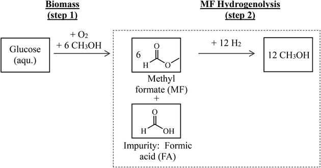
Hence, the combination of biomass oxidation to MF (using oxygen from water electrolysis according to Maerten et al.16) and the subsequent hydrogenolysis (using hydrogen from water electrolysis) described above offers an attractive path for synthesizing green MeOH. A simplified flow scheme of this two-step process is shown in Fig. 1. By balancing the entire reaction sequence and by taking into account that MeOH is used as the solvent in step 1, up to 6 mols of MeOH are formed from each mol of glucose.
Since biomass naturally contains water and its drying is energy intensive, biomass oxidation (step 1 in Fig. 1) results in the presence of water and therefore formation of FA in certain amounts.16 Purification of MF would be energy intensive and linked to product losses. Therefore, it is attractive to use the crude product mixture from step 1 directly and without further purification in step 2. In this contribution, it is clarified how FA affects the catalytic transformation in process step 2. We therefore focus on the hydrogenolysis of MF with particular attention on FA impurities in the MF feedstock affecting the catalyst stability and performance.
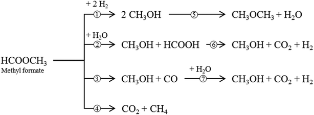
Besides the main reaction (1), various undesirable consecutive and side-reactions can occur during MF hydrogenolysis (see Fig. 2). In the presence of water, MF can react to form FA and MeOH in a hydrolysis reaction (2). FA can further decompose to CO2 and H2 (6). Decarbonylation (3) and decarboxylation (4) of MF are side reactions that form CO and CO2, respectively. Furthermore, MeOH condensation to DME (5) and the water–gas shift reaction (WGS, 7) can occur within the complex reaction network.
According to the literature, MF hydrogenolysis has been investigated using heterogeneously catalysed slurry phase and gas phase processes.18,21 Gas phase reactions enable significantly lower system pressures (10 bar) compared to liquid phase processes (50–100 bar).18 Furthermore, separation of the product mixture from the catalyst is straightforward in the gas phase process. Slurry phase reactions offer the advantage of a better temperature control and catalyst utilization because smaller catalyst particles can be applied.22 In both process operation modes, copper containing catalysts, such as CuO/ZnO/Al2O3,18 copper-chromite19 or RANEY®-copper21 have been applied so far. However, copper sintering at comparably low temperatures of below 300 °C is a known effect in supported catalysts, such as CuO/ZnO,23 demonstrating the weak bonding of copper species within the solid matrix. Furthermore, these catalysts are sensitive for active metal leaching, for example in the presence of strong acids.24,25 Spinel catalysts are of particular interest for this study as they have, conversely, shown high stability against chemical corrosion by strong acids in different applications,26–28 for instance in PEM electrolyzers, where good stability against chemical corrosion is necessary. Spinels are crystalline mixed metal oxides with the general sum formula of AB2O4. In normal spinels, A2+ ions occupy tetrahedral and B3+ ions occupy octahedral positions in the crystal structure. Within the crystalline structure, catalytically active sites are ultimately dispersed and stabilized, making them potentially more stable against corrosion compared to conventional supported catalysts.29 In comparison to typical supported catalysts, where the active material is deposited on a support material, in spinel catalysts it is embedded into the crystal phase.
In the present study, we evaluate the performance of different Cu catalysts in liquid as well as in gas phase hydrogenolysis of MF containing FA impurities as found in biomass oxidation products. In this context, we introduce a novel Cu0.9Al2O4 spinel catalyst and compare its activity and its stability against the FA impurities with classical supported Cu-catalysts.
Materials and methods
Copper catalysts
Different commercially available copper catalysts were used without further purification, unless otherwise stated (CuO/MgO/ZnO/Al2O3 from Alfa Aesar, wCu = 50 wt%, abbreviated with CuO/ZnO; and CuO/Cr2O3 from Aldrich, wCu = 37 wt%). In addition, a spinel catalyst with the formula Cu0.9Al2O4 was prepared by coprecipitation of the corresponding metal nitrates according to the following protocol: stoichiometric amounts of Cu(NO3)2 trihydrate (≥99.5%, Supelco) and Al(NO3)3 nonahydrate (98.5%, VWR Chemicals) were dissolved in deionized water. Precipitation of the hydroxides was initiated by dropwise addition of 2 M NaOH under continuous stirring until a pH-value of 9 was reached. After filtration and washing with deionized water, the solid was dried at 75 °C for 12 h. Afterwards, the spinel catalysts were formed, by calcining the solid powder for 6 h in air at 950 °C (starting from room temperature with a heating rate of 5 K min−1). Such high temperatures are necessary to reach high phase purity of the desired Cu0.9Al2O4![[thin space (1/6-em)]](https://www.rsc.org/images/entities/char_2009.gif) 30 spinel structure.
30 spinel structure.
Catalyst characterization
Specific surface area (SBET) of the catalysts was obtained by N2-physisorption measurements at a temperature of 77 K using a Quadrasorb SI from Quantachrome Instruments by the BET approach. The samples were dried for 12 h at 175 °C before measurement.The active copper surface area (SRFC) of each catalyst was determined by nitrous oxide decomposition also known as reactive frontal chromatography (RFC), as reported by Hinrichsen et al.,31 using an Autochem II 2920 instrument. For each analysis, 300 mg of catalyst was filled into the glass reactor. Before each RFC-experiment, a temperature programmed reduction step (TPR) was performed. For this purpose, the catalyst was heated in a 20 vol% H2 stream diluted in Ar until a temperature of 250 °C was reached (temperature ramp: 5 K min−1). After 1 h holding time, the catalyst was cooled to 45 °C in a 50 cm3 min−1 helium flow and then the nitrous oxide decomposition experiment was started. During the decomposition experiment, the catalyst was flushed with 0.5 vol% N2O in helium, and non-converted N2O was condensed in a cold trap. Using a thermal conductivity sensor (TCD) the amount of released N2 could be determined. By reproducing a measurement with our CuO/ZnO-catalyst three times, a relative standard deviation for SRFC was determined to be 3.4%. This value was used as the statistical error margin for all presented SRFC data.
To analyze the elemental composition of each metal containing solutions, inductively coupled plasma optical emission spectroscopy (ICP-OES, Plasma 400 from PerkinElmer) was applied. Solid samples were digested in a mixture of hydrochloric and nitric acid to dissolve all metal components.
X-ray powder diffraction (XRD) was used for the determination of the crystal structure of catalysts. The diffractograms were recorded on a Pananalytic X-Pert instrument (Philips) using CuKα radiation, angles of 10–90° and a step size of 0.017° Θ. Furthermore, attenuated total reflection infrared (ATR-IR) measurements of the catalysts after contact with FA were conducted using a FT-IR spectrometer (Jasco model 4100).
Catalytic reaction and analysis equipment
![[thin space (1/6-em)]](https://www.rsc.org/images/entities/char_2009.gif) :
:![[thin space (1/6-em)]](https://www.rsc.org/images/entities/char_2009.gif) nCu = 212 mol mol−1). For a typical slurry phase experiment, 1.67 mol of MF (VWR; ≥97%) was filled into a 300 mL hastelloy autoclave (Parr Instruments, for more information see Fig. S1 in the ESI†). The autoclave was sealed with a PTFE ring. The stirrer was set to 1000 rpm and after reaching 175 °C, the hydrogen partial pressure was adjusted to 45 barH2 (ptotal = 80 barg). The reaction conditions were maintained for a certain reaction time. During the reaction, H2 was fed continuously, to keep its partial pressure constant throughout the experiment.
nCu = 212 mol mol−1). For a typical slurry phase experiment, 1.67 mol of MF (VWR; ≥97%) was filled into a 300 mL hastelloy autoclave (Parr Instruments, for more information see Fig. S1 in the ESI†). The autoclave was sealed with a PTFE ring. The stirrer was set to 1000 rpm and after reaching 175 °C, the hydrogen partial pressure was adjusted to 45 barH2 (ptotal = 80 barg). The reaction conditions were maintained for a certain reaction time. During the reaction, H2 was fed continuously, to keep its partial pressure constant throughout the experiment.
In this study, we were interested in the influence of FA impurities on the catalytic performance of different Cu-catalysts. Therefore, all catalysts were examined in three different scenarios:
• A: In a reference experiment, each catalyst was applied for MF hydrogenolysis in the absence of any FA.
• B: In this scenario, 0.4 g of the calcined catalyst was brought into contact with 8 g of a solution of FA in MF (pH = 1.5, nMF![[thin space (1/6-em)]](https://www.rsc.org/images/entities/char_2009.gif) :
:![[thin space (1/6-em)]](https://www.rsc.org/images/entities/char_2009.gif) nFA = 19) prior to the hydrogenolysis reaction. The suspension was stirred for 1 h at RT using a magnetic stirrer. Afterwards, the catalyst was filtered, washed and again treated with the FA–MF-solution. This procedure was repeated in total 10 times. After 10 washing cycles, the catalyst was dried using a rotary evaporator (72 mbar, 60 °C, 2 h) and was then reduced as described above and tested in hydrogenolysis, using pure MF as the substrate, as described in the reference scenario A. Both catalyst and filtrate were further analysed after this procedure.
nFA = 19) prior to the hydrogenolysis reaction. The suspension was stirred for 1 h at RT using a magnetic stirrer. Afterwards, the catalyst was filtered, washed and again treated with the FA–MF-solution. This procedure was repeated in total 10 times. After 10 washing cycles, the catalyst was dried using a rotary evaporator (72 mbar, 60 °C, 2 h) and was then reduced as described above and tested in hydrogenolysis, using pure MF as the substrate, as described in the reference scenario A. Both catalyst and filtrate were further analysed after this procedure.
• C: The aforementioned MF–FA solution was directly used in the slurry phase hydrogenolysis experiment.
In all experiments the molar ratio of FA to Cu was kept constant at nFA![[thin space (1/6-em)]](https://www.rsc.org/images/entities/char_2009.gif) :
:![[thin space (1/6-em)]](https://www.rsc.org/images/entities/char_2009.gif) nCu = 10.8 mol mol−1. After cooling the reactor, the liquid reaction products were analysed using an Agilent GC 8890 with a CP-Sil 5 CB column (Agilent Technologies) and a FID-detector with a polyarc-methanizer. For quantification of the liquid components, dimethylsulfoxide was used as internal standard. The gaseous products were identified and quantified using a Shimadzu GC2020 gas chromatograph equipped with a ShinCarbon ST 80/100 column and a MS-detector.
nCu = 10.8 mol mol−1. After cooling the reactor, the liquid reaction products were analysed using an Agilent GC 8890 with a CP-Sil 5 CB column (Agilent Technologies) and a FID-detector with a polyarc-methanizer. For quantification of the liquid components, dimethylsulfoxide was used as internal standard. The gaseous products were identified and quantified using a Shimadzu GC2020 gas chromatograph equipped with a ShinCarbon ST 80/100 column and a MS-detector.
 . After reduction, the desired pressure and flow rates of the reaction substrates were adjusted. The liquid MF was continuously pumped into a liquid evaporator (Adrop) using a HPLC-pump (Wadose, Flusys). The gaseous MF was mixed with H2 stream and fed into the reactor. Typically, a total volume flow of 704 mln min−1 with a molar H2
![[thin space (1/6-em)]](https://www.rsc.org/images/entities/char_2009.gif) :
:![[thin space (1/6-em)]](https://www.rsc.org/images/entities/char_2009.gif) MF ratio of 5.8
MF ratio of 5.8![[thin space (1/6-em)]](https://www.rsc.org/images/entities/char_2009.gif) :
:![[thin space (1/6-em)]](https://www.rsc.org/images/entities/char_2009.gif) 1 was adjusted. Unless otherwise mentioned, the catalytic reaction was performed at 10 barg and in the temperature range between 150 and 260 °C.
1 was adjusted. Unless otherwise mentioned, the catalytic reaction was performed at 10 barg and in the temperature range between 150 and 260 °C.
For online product gas analysis, a micro-GC (Inficon) was used. The latter was equipped with a Rt-Molsieve 5 column for the separation of permanent gases and a Rt-Q-bond column for the separation of organic compounds. Each column was connected to a TCD-detector.
Calculation details for reaction engineering parameters as well as for the determination of kinetic parameters are given in the ESI.†
Results and discussion
Hydrogenolysis of methyl formate in slurry phase mode
Three different copper catalysts were investigated with regard to their activity in the hydrogenolysis of MF. Besides the two commercial catalysts, CuO/ZnO and CuO/Cr2O3, a self-synthesized Cu0.9Al2O4 spinel catalyst was applied. XRD analysis was used to verify the formation of the desired Cu0.9Al2O4 spinel phase (see Fig. S3 in the ESI†).As stated above, the key aspect of our study is the development of a copper-based hydrogenolysis catalyst that is active and stable in the presence of relevant amounts of FA. Consequently, the three Cu-catalysts were applied according to the scenarios A, B and C described in the experimental section. In Table 1, the results of these experiments are presented. The catalyst specific values (weight fraction wCu/Cr, SBET, SRFC) refer to the analysis of the catalyst after the reaction. CH4 formation was below 0.1% in all experiments and is therefore not shown in Table 1.
![[thin space (1/6-em)]](https://www.rsc.org/images/entities/char_2009.gif) :
:![[thin space (1/6-em)]](https://www.rsc.org/images/entities/char_2009.gif) nCu = 212 mol mol−1, mMF
nCu = 212 mol mol−1, mMF![[thin space (1/6-em)]](https://www.rsc.org/images/entities/char_2009.gif) :
:![[thin space (1/6-em)]](https://www.rsc.org/images/entities/char_2009.gif) mcat. = 100 g g−1, CuO/Cr2O3: nMF
mcat. = 100 g g−1, CuO/Cr2O3: nMF![[thin space (1/6-em)]](https://www.rsc.org/images/entities/char_2009.gif) :
:![[thin space (1/6-em)]](https://www.rsc.org/images/entities/char_2009.gif) nCu = 1910 mol mol−1, mMF
nCu = 1910 mol mol−1, mMF![[thin space (1/6-em)]](https://www.rsc.org/images/entities/char_2009.gif) :
:![[thin space (1/6-em)]](https://www.rsc.org/images/entities/char_2009.gif) mcat. = 653 g g−1, Cu0.9Al2O4: nMF
mcat. = 653 g g−1, Cu0.9Al2O4: nMF![[thin space (1/6-em)]](https://www.rsc.org/images/entities/char_2009.gif) :
:![[thin space (1/6-em)]](https://www.rsc.org/images/entities/char_2009.gif) nCu = 212 mol mol−1, mMF
nCu = 212 mol mol−1, mMF![[thin space (1/6-em)]](https://www.rsc.org/images/entities/char_2009.gif) :
:![[thin space (1/6-em)]](https://www.rsc.org/images/entities/char_2009.gif) mcat. = 67 g g−1, B: usage of catalysts after a 600 minutes treatment with FA–MF-solution, CuO/ZnO: mMF
mcat. = 67 g g−1, B: usage of catalysts after a 600 minutes treatment with FA–MF-solution, CuO/ZnO: mMF![[thin space (1/6-em)]](https://www.rsc.org/images/entities/char_2009.gif) :
:![[thin space (1/6-em)]](https://www.rsc.org/images/entities/char_2009.gif) mcat. = 100 g g−1, CuO/Cr2O3: mMF
mcat. = 100 g g−1, CuO/Cr2O3: mMF![[thin space (1/6-em)]](https://www.rsc.org/images/entities/char_2009.gif) :
:![[thin space (1/6-em)]](https://www.rsc.org/images/entities/char_2009.gif) mcat. = 653 g g−1 Cu0.9Al2O4: mMF
mcat. = 653 g g−1 Cu0.9Al2O4: mMF![[thin space (1/6-em)]](https://www.rsc.org/images/entities/char_2009.gif) :
:![[thin space (1/6-em)]](https://www.rsc.org/images/entities/char_2009.gif) mcat. = 67 g g−1, C: usage of fresh catalysts with FA–MF-solution as reaction substrate, CuO/ZnO: nMF
mcat. = 67 g g−1, C: usage of fresh catalysts with FA–MF-solution as reaction substrate, CuO/ZnO: nMF![[thin space (1/6-em)]](https://www.rsc.org/images/entities/char_2009.gif) :
:![[thin space (1/6-em)]](https://www.rsc.org/images/entities/char_2009.gif) nCu = 212 mol mol−1, CuO/Cr2O3: nMF
nCu = 212 mol mol−1, CuO/Cr2O3: nMF![[thin space (1/6-em)]](https://www.rsc.org/images/entities/char_2009.gif) :
:![[thin space (1/6-em)]](https://www.rsc.org/images/entities/char_2009.gif) nCu = 1910 mol mol−1, Cu0.9Al2O4: nMF
nCu = 1910 mol mol−1, Cu0.9Al2O4: nMF![[thin space (1/6-em)]](https://www.rsc.org/images/entities/char_2009.gif) :
:![[thin space (1/6-em)]](https://www.rsc.org/images/entities/char_2009.gif) nCu = 212 mol mol−1. Standard deviations are calculated, based on the relative standard deviations, determined from the reproduction experiments
nCu = 212 mol mol−1. Standard deviations are calculated, based on the relative standard deviations, determined from the reproduction experiments
| Scenario | X MF/% | S MeOH/% | S CO/% | S CO2/% | P active/gMeOH m−2Cu h−1 | w Cu/wt% | w Cr/wt% | S BET/m2 g−1 | S RFC/mCu2 g−1 | |
|---|---|---|---|---|---|---|---|---|---|---|
| Cu0.9Al2O4: usage of two different catalyst batches for the experiments A and B vs. A* and C*. | ||||||||||
| CuO/ZnO | A – fresh | 17 ± 2 | 96 ± 1 | 3.7 ± 0.3 | 0.3 ± 0.1 | 0.08 | 50 | — | 95 | 44 ± 2 |
| B – treated | 10 ± 1 | 93 ± 1 | 6.9 ± 0.5 | 0.1 ± 0.0 | 0.10 | 31 | — | 91 | 22 ± 1 | |
| C – FA | 11 ± 1 | 88 ± 1 | 7 ± 0.5 | 5.0 ± 0.3 | 0.03 | 51 | — | 101 | 23 ± 1 | |
| CuO/Cr2O3 | A – fresh | 43 ± 4 | 99 ± 1 | 0.9 ± 0.1 | 0.1 ± 0.0 | 11.52 | 37 | 28 | 41 | 15 ± 1 |
| B – treated | 35 ± 3 | 95 ± 1 | 3 ± 0.2 | 2.0 ± 0.1 | 11.22 | 34 | 26 | 42 | 13 ± 1 | |
| C – FA | 3 ± 1 | 94 ± 1 | 3.7 ± 0.3 | 2.3 ± 0.1 | 0.65 | 39 | 29 | 95 | 11 ± 1 | |
| Cu0.9Al2O4 | A – fresh | 26 ± 3 | 99 ± 1 | 0.9 ± 0.1 | 0.1 ± 0.0 | 1.66 | 31 | — | 16 | 1.8 ± 0.1 |
| B – treated | 30 ± 3 | 99 ± 1 | 0.9 ± 0.1 | 0.1 ± 0.0 | 2.14 | 31 | — | 15 | 1.7 ± 0.1 | |
| A* – fresh | 31 ± 3 | 95 ± 1 | 4.8 ± 0.3 | 0.2 ± 0.0 | 3.57 | 30 | — | 8 | 1.1 ± 0.1 | |
| C* – FA | 19 ± 2 | 96 ± 1 | 1.5 ± 0.1 | 2.5 ± 0.1 | 1.26 | 29 | — | 9 | 1.1 ± 0.1 | |
First, the performance of the three catalysts is compared using pure MF as the substrate and without previous FA-treatment (scenario A). For all catalysts, the selectivity to MeOH is very similar (SMeOH = 96–99%) with CO and CO2 being the only side products. Interestingly, CuO/Cr2O3 (11.52 gMeOH mCu−2 h−1) shows a significantly higher productivity compared to CuO/ZnO (0.08 gMeOH mCu−2 h−1) and the Cu0.9Al2O4 spinel catalyst (1.66 gMeOH mCu−2 h−1). It is important to note, however, that the non-porous Cu0.9Al2O4 catalyst shows its productivity with a much smaller active surface area (see SRFC in Table 1).
The influence of an FA treatment of the catalysts before application can be derived from the comparison of scenarios A and B. According to Table 1, the MF conversion decreases significantly with CuO/ZnO and CuO/Cr2O3 after FA-treatment. This decrease can be correlated with the loss in active copper surface area after FA-treatment. For CuO/ZnO the active surface area reduces from 44 mCu2 g−1 to 22 mCu2 g−1, for CuO/Cr2O3 the reduction is from 15 mCu2 g−1 to 13 mCu2 g−1. Analysis of the catalysts by ICP-OES (wCu/Cr in Table 1) after FA-treatment shows a loss of Cu (and also Cr for CuO/Cr2O3) after the leaching experiments matching the decreased copper surface area. It is interesting to note that the FA-treatment (B) does also slightly affect the selectivity in the MF hydrogenolysis with CuO/ZnO and CuO/Cr2O3, as significantly higher selectivity to the side-products CO and CO2 were found. Under consideration of the previously determined error margins from three reproduction experiments (see chapter 3, Table S1 in the ESI†) also the decrease in SMeOH after FA treatment is significant. In particular, for CuO/ZnO (B) the formation of CO increases from SCO = 3.7% to 6.9%. For Cu0.9Al2O4, in contrast, the MF conversion is slightly increased from 26% (A) to 30% (B) after FA-treatment. Moreover, the copper content and the specific surface area of the catalyst stay almost unchanged after the FA-treatment. Furthermore, no change in selectivity after FA-treatment was observed for the spinel catalyst Cu0.9Al2O4.
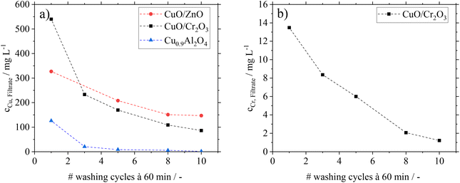
Besides the analysis of catalysts after FA-treatment, filtrates from the washing cycles in experiments B were analysed by ICP-OES. In Fig. 3, the copper and chromium contents in the filtrates are shown.
For CuO/ZnO and CuO/Cr2O3, significant copper leaching is found during the washing cycles with the representative FA–MF mixture. Even after ten washing cycles a considerable amount of Cu is still detectable in the filtrate. This hints to the fact that permanent contact of these catalysts with FA would lead to complete Cu leaching. The same behaviour is found for CuO/Cr2O3 with regard to leaching of toxic Cr, excluding this catalyst for application in the here proposed green MeOH synthesis concept. The filtrates from the CuO/ZnO and CuO/Cr2O3 catalysts are characterized by a blue coloration (see ESI Fig. S4 and 5†), which is typical for the soluble copper formate species Cu(HCOO)2.32 From these results we conclude, that the decrease in conversion after previous treatment of the catalysts with FA is caused by leaching of the active component.
Interestingly, the Cu0.9Al2O4 spinel catalyst shows a different behaviour concerning leaching and the coloration of filtrates (see Fig. S6 in the ESI†). While some small amounts of Cu were leaching in the first washing cycle, the following 9 cycles showed only traces of copper in the filtrate. We relate the small amount of Cu in the filtrate of the first washing cycle to a leftover of copper oxide (CuO) from material synthesis After removal of this residue in the first washing cycle, no further copper leaching from the catalysts is found in the presence of FA.
All catalysts were analysed before and after the washing cycle using FT-IR-spectroscopy in order to investigate residual FA on their surface. The corresponding spectra before (A) and after (B) FA-treatment are shown in Fig. 4.
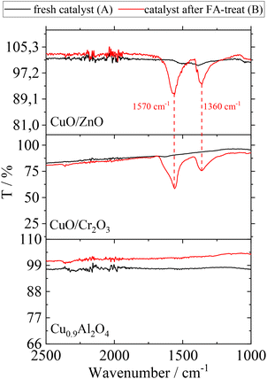 | ||
| Fig. 4 ATR-IR spectra of CuO/ZnO, CuO/Cr2O3 and Cu0.9Al2O4 before (A) and after (B) contact with FA; assignment of peaks: carboxylate ion of formate species (1570 cm−1 asymmetric stretch and 1360 cm−1 symmetric stretch).33 | ||
The examination of FA-treated catalysts (according to scenario B) by ATR-IR revealed that Cu(HCOO)2 is indeed present on CuO/ZnO and CuO/Cr2O3.34 With regard to the observed increase in side-product formation, the loss of active component leads to a change of the surface texture and potentially changes in the interaction between catalyst and substrates. In contrast, the ATR-IR analysis of the Cu0.9Al2O4 catalyst after FA-treatment did not show the characteristic signals for Cu(HCOO)2 species.
In a next set of experiments, the influence of FA impurities on the different Cu-based catalysts is studied under reaction conditions. Therefore, FA is added to the substrate MF and hydrogenolysis reactions are performed. The results can be derived from comparing the scenario A and C in Table 1. All Cu-catalysts show a decreasing activity with the lowest relative decrease in activity for the spinel catalyst. While wCu and wCr values are not affected by the FA-treatment, a decrease in the active copper surface area (SRFC) is observed for CuO/ZnO and CuO/Cr2O3, but not for the spinel catalyst. These results suggest, that the Cu-formate formation leads to a change in the morphology of copper species but only to limited copper leaching. The decomposition of copper formates at elevated temperatures of 200 °C has already been studied extensively in literature32 showing the formation of copper clusters. Gelwey et al. observed that after decomposition of copper formate, the remaining copper sintered at temperatures up to 200 °C. Thus, we hypothesize that in our FA-treatment experiments (scenario C) copper formate species are formed in the first step and decompose under the formation of such sintered copper clusters in the second. Another reason for the reduced hydrogenolysis activity is the competing conversion of FA on the active centres. As the CO2-formation is significantly increased in all experiments a decomposition of FA to CO2 and H2 is most likely.
We conclude from these results that the spinel catalyst Cu0.9Al2O4 is stable against formation of Cu(HCOO)2 in the presence of FA. This excellent resistance can presumably be related to the spinel structure, in which copper is strongly bond in the regular framework, avoiding its leaching by Cu-formate formation. This interpretation is also supported by TPR-studies comparing CuO and Cu0.9Al2O4 (see Fig. S7 in the ESI†). Whereas CuO shows a reduction peak at around 250 °C, the first reduction peak for Cu0.9Al2O4 appears only at 426 °C, demonstrating the higher stability of the copper ions within the Cu0.9Al2O4 catalyst. Consequently, the use of Cu0.9Al2O4 compared to the commercial CuO/ZnO and CuO/Cr2O3 catalysts avoids copper and chromium leaching, making it the only stable catalytic system for our desired combination of the two process steps. By using Cu0.9Al2O4, a complex and cost-intensive purification of the MF hydrogenolysis feedstock stream from FA impurities is not required.
Influence of gaseous formic acid on Cu-catalysts
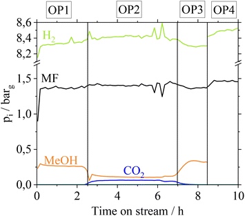
MF hydrogenolysis is often performed in gas phase reactor concepts. Working in gas phase could be advantageous in our case, since contact of Cu with gaseous FA might not lead to metal leaching. Nevertheless, a possible condensation of FA, e.g. during start-up and shut-down phases cannot be excluded. Furthermore, renewable H2 provision is time dependent, suggesting a dynamic operation of MF hydrogenolysis.35 In a dynamic operation mode, however, local condensation of FA becomes very likely due to a time dependent change of reaction temperatures. To examine the stability of the Cu-catalysts in a continuous gas phase process, we additionally investigated the influence of gaseous FA on the Cu-catalysts in a glass setup. For more detailed information on these experiments refer to the ESI chapter 4.† Similar to how after the liquid phase contact, the CuO/ZnO- and CuO/Cr2O3-catalysts suffer from a loss in active copper surface area due to Cu- and Cr-leaching, they also behave after contact with gaseous FA. In a technical scenario with a FA-polluted feedstock, leached Cu- and Cr-species would contaminate the gas phase reactor and its outlet parts, if CuO/ZnO and CuO/Cr2O3 catalysts were applied. In contrast, Cu0.9Al2O4-catalysts show a high stability of the active copper surface after contact with gaseous FA. Based on these results we were confident to investigate the Cu0.9Al2O4 catalyst in continuous MF hydrogenolysis (setup see Fig. S2 in the ESI†) using a mixed MF/FA-feed, without risking the reactor to be coated by leached Cu/Cr-species. The catalyst was examined at different operation points (OPs in Fig. 5). Due to analytical limits, it was not possible to quantify remaining FA in the product stream in our setup.For the first operation point (OP1), pure MF is used as a substrate and a MeOH partial pressure of 0.25 barg is reached at the outlet. In OP2, a FA–MF mixture (nMF![[thin space (1/6-em)]](https://www.rsc.org/images/entities/char_2009.gif) :
:![[thin space (1/6-em)]](https://www.rsc.org/images/entities/char_2009.gif) nFA = 19 mol mol−1) is fed into the reactor for approx. 4 hours. According to Fig. 5, CO2 with a partial pressure of pCO2 = 0.06 bar is only formed in OP2. Furthermore, a slight increase of pH2 from 8.2 barg (OP1) to 8.4 barg (OP2) is observed revealing that FA is converted to CO2 and H2. In contrast, pMeOH decreases from 0.26 barg (OP 1) to 0.1 barg (OP2) while pMF slightly increases, indicating a lower conversion of MF to MeOH caused by the presence of the competitive substrate FA. Switching again to pure MF as substrate (OP3), pMeOH increases to the same level as in OP1, showing that no irreversible deactivation of Cu0.9Al2O4 takes place after contact with FA. By feeding the FA–MF mixture through the reference bypass (Fig. 5, OP4) no increase of pCO2 was detected, demonstrating, that the decomposition of FA into CO2 and H2 during OP2 is a catalytic and not a thermally induced process. A thermal decomposition of FA, without catalyst could not be observed.
nFA = 19 mol mol−1) is fed into the reactor for approx. 4 hours. According to Fig. 5, CO2 with a partial pressure of pCO2 = 0.06 bar is only formed in OP2. Furthermore, a slight increase of pH2 from 8.2 barg (OP1) to 8.4 barg (OP2) is observed revealing that FA is converted to CO2 and H2. In contrast, pMeOH decreases from 0.26 barg (OP 1) to 0.1 barg (OP2) while pMF slightly increases, indicating a lower conversion of MF to MeOH caused by the presence of the competitive substrate FA. Switching again to pure MF as substrate (OP3), pMeOH increases to the same level as in OP1, showing that no irreversible deactivation of Cu0.9Al2O4 takes place after contact with FA. By feeding the FA–MF mixture through the reference bypass (Fig. 5, OP4) no increase of pCO2 was detected, demonstrating, that the decomposition of FA into CO2 and H2 during OP2 is a catalytic and not a thermally induced process. A thermal decomposition of FA, without catalyst could not be observed.
As besides FA water is also a probable by-product from the biomass oxidation, we also investigated the influence of water on the hydrogenolysis reaction using the Cu0.9Al2O4 catalyst (refer to Fig. S12 in the ESI†). It can be seen, that traces of water lead to a slight decrease in conversion, which can be referred to as the competing hydrolysis reaction of methyl formate and subsequent dehydrogenation of FA to CO2 and H2. However, the experiments showthat the decrease in conversion is reversible.
Hydrogenolysis parameter study with Cu0.9Al2O4 in the continuous gas phase setup
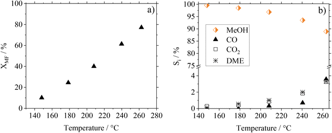
As the kinetic behavior of Cu0.9Al2O4-spinel in MF hydrogenolysis has not been described in the literature yet, we investigated the temperature, residence time and pressure dependence of this reaction as well as the long-term stability of the catalyst. In Fig. 6(a) and (b) the conversion and selectivity data depending on the temperature for the Cu0.9Al2O4-catalyst are shown. Comparative information on the performance of CuO/ZnO and CuO/Cr2O3 in the respective experiments can be found in Fig. S13 in the ESI.† The investigations were carried out in a continuous gas phase setup in the range between 150 and 260 °C using pure MF as starting material.As expected from the temperature dependency according to Arrhenius, MF conversion increases from 10% at 150 °C to 80% at 260 °C. At the same time, the MeOH selectivity SMeOH decreases from 99% at 150 °C to 89% at 260 °C, with increasing formation of CO, CO2 and DME as side-products. These side products originate from the known decarbonylation of MF at higher temperatures18 and from consecutive WGSR and MeOH condensation reactions.
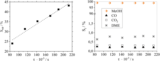
Fig. 7 shows a residence time variation (by adjusting the flow rate) to study its influence on the catalytic performance of Cu0.9Al2O4.
As expected, the conversion of MF increases with higher residence time. Regarding product distribution, the residence time has no significant influence on the product selectivity in the examined range of flow rates and conversions. At the here-selected temperature of 188 °C, the selectivity towards MeOH was ≥98% over the whole residence time range making this catalyst system suitable for different scenarios of reactant availability.
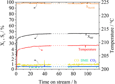
The long-term stability of catalysts is of great importance for its usage in industrial scale. We investigated the stability of the Cu0.9Al2O4 catalyst within a 115 h experiment under constant reaction conditions. In Fig. 8 the conversion XMF and the product selectivity Si are shown as a function of time on stream.
Following an induction phase at the beginning of the experiment (until 24 h), constant conversion XMF of 47% is reached over more than 110 h. Under these steady-state conditions, the MeOH selectivity is about 98%. Furthermore, an experiment with multiple temperature variations was performed (see Fig. S14 in the ESI†). Herein we found, that even after treating the catalyst at temperatures of up to 260 °C no deactivation takes place. The conversion and selectivity reach the same level when the reference conditions are applied after several temperature cycles. As previously described in MF hydrogenolysis literature,18,36 Cu-catalysts can suffer from deactivation due to undesired polymerization of formaldehyde-species, that are formed during reaction. Interestingly, during our experiments we did not observe any deactivation behaviour, making the presented spinel catalyst a very interesting candidate for further technical development.
Determination of kinetic parameters for the novel Cu0.9Al2O4 catalyst
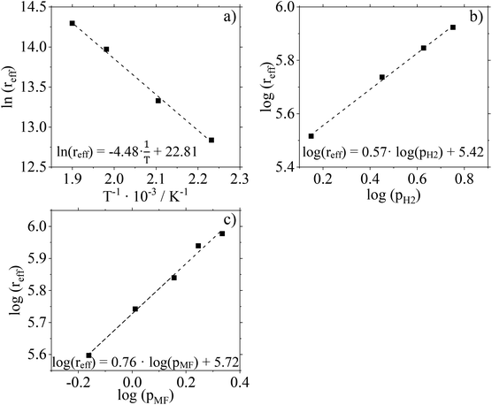
For further kinetic characterization of our Cu0.9Al2O4 catalyst we determined kinetic parameters for a power law model (activation energy, reaction orders). The apparent activation energy EA,eff was determined to be 37.3 kJ mol−1 by using the Arrhenius plot (Fig. 9a and Fig. S15 in ESI†). Compared to activation energies determined for CuO/ZnO and CuO/Cr2O3 (see ESI Fig. S16 and 17† for more information) this value is significantly smaller (see Table 2). It should be mentioned in this context, that the applied Cu0.9Al2O4 catalysts are non-porous, excluding pore diffusion effects. Comparably low activation energies were already observed in low-temperature MeOH synthesis using CuZn-spinel catalysts.37 By varying the composition of the spinel catalyst, the authors observed a dependence of apparent activation energy on the latter (46 kJ mol−1 for Cu0.8Zn0.2Cr2O4 and 71 kJ mol−1 for Cu0.8Zn0.2Cr0.5Fe1.5O4). Prudnikova et al. have identified a correlation of the copper coordination surrounding and the activation energy.37 In future studies, further analysis, such as XPS, would be helpful to understand the influence of copper coordination surrounding on activity and activation energy. We have confirmed the reliability of our experimental setup by determining the activation energy for CuO/Cr2O3 in very good agreement to literature data (copper chromite catalyst: EA,eff = 83 kJ mol−1 (ref. 19)).| Catalyst | E A,eff/kJ mol−1 | n MF/— | n H2/— |
|---|---|---|---|
| CuO/ZnO | 69.5 | 0.59 | 1.05 |
| CuO/Cr2O3 | 84.5 | 0.33 | 1.01 |
| Cu0.9Al2O4 | 37.3 | 0.76 | 0.57 |
Fig. 9b and c show the results of feed composition variation to determine effective reaction orders with respect to the H2 and MF partial pressures. The experiments were carried out at 210 °C and a total pressure of 10 barg. To guarantee identical residence times, N2 was used as inert dilution media when necessary. Conversion and selectivity data of these experiments are given in Fig. S18 (ESI†).
According to the slopes of the corresponding plots, the reaction order with respect to H2 can be calculated to 0.57. For MF, the reaction order is determined to be 0.76. Compared to data recorded for the two commercial Cu-catalysts (see Table 2 and ESI Fig. S19–22†) used in this study, a significant difference is observed. The spinel catalyst Cu0.9Al2O4 shows a stronger dependence on the substrate partial pressure of MF but a weaker dependence on the substrate partial pressure of H2 compared to the other catalysts.
Conclusion
Within this work, we have proposed a new route to generate green MeOH from lignocellulosic biomass, consisting of two sequential highly selective and atom efficient reaction steps, namely biomass oxidation to MF/FA followed by MF hydrogenolysis. In this work our special interest was on the tolerance of the Cu catalysts against FA in methyl formate hydrogenolysis, which is a common contaminant of MF from the previous biomass oxidation process.10We showed that in the liquid and gas phases, commercial supported catalysts such as CuO/ZnO/MgO/Al2O3 or CuO/Cr2O3 suffer from leaching of the active material (Cu, Cr) in the presence of FA. This dissolution leads to an irreversible decrease of activity by the formation of mobile copper and chromium formate species. In contrast, a self-synthesized Cu0.9Al2O4 catalyst shows high stability against dissolution of the active material in the presence of FA in liquid and gas phase. We trace this high stability back to the crystalline structure of the novel spinel catalyst. Due to the stronger binding of copper in the crystalline framework, the catalyst shows high resistance against dissolution of the active component. Finally, Cu0.9Al2O4 was tested in continuous operation for more than 110 h without any loss in activity or selectivity. The observed activity is impressive, given the fact that this spinel catalyst still leaves room for optimization, e.g. with respect to supporting the active phase or adjusting the calcination temperature or time.
Author contributions
Conceptualization: VH, MS, TF, PW, and PS. Investigation: VH, JI, and DW. Project administration: MS and PS. Supervision: TF, PW, and PS. Writing – original draft: VH, MS, TF, PW, and PS.Conflicts of interest
The authors declare no conflict of interest.Acknowledgements
The authors gratefully acknowledge the funding of the Bavarian Ministry of Economic Affairs, Regional Development and Energy.References
- Statista, Production capacity of methanol worldwide from 2018 to 2020, with a forecast for 2030, can be found under https://www.statista.com/statistics/1065891/global-methanol-production-capacity/, 2022.
- K. A. Ali, A. Z. Abdullah and A. R. Mohamed, Renewable Sustainable Energy Rev., 2015, 44, 508–518 CrossRef CAS.
- D. W. Stephan, Nature, 2013, 495, 54–55 CrossRef CAS PubMed.
- A. Jess and P. Wasserscheid, Chemical Technology: An Integral Textbook, Wiley, 2020 Search PubMed.
- A. Al-Mamoori, A. Krishnamurthy, A. A. Rownaghi and F. Rezaei, Energy Technol., 2017, 5, 834–849 CrossRef.
- M. Bertau, H. Offermanns, L. Plass, F. Schmidt and H. J. Wernicke, Methanol: The Basic Chemical and Energy Feedstock of the Future: Asinger's Vision Today, Springer Berlin Heidelberg, 2014 Search PubMed.
- G. Pipitone and O. Bolland, Int. J. Greenhouse Gas Control, 2009, 3, 528–534 CrossRef CAS.
- J. Schittkowski, H. Ruland, D. Laudenschleger, K. Girod, K. Kähler, S. Kaluza, M. Muhler and R. Schlögl, Chem. Ing. Tech., 2018, 90, 1419–1429 CrossRef CAS.
- M. Asadullah, Renewable Sustainable Energy Rev., 2014, 40, 118–132 CrossRef CAS.
- S. Deutz and A. Bardow, Nat. Energy, 2021, 6, 203–213 CrossRef CAS.
- J. Kemper, Int. J. Greenhouse Gas Control, 2015, 40, 401–430 CrossRef CAS.
- P. Preuster and J. Albert, Energy Technol., 2018, 6, 501–509 CrossRef CAS.
- J. Albert, R. Wölfel, A. Bösmann and P. Wasserscheid, Energy Environ. Sci., 2012, 5, 7956–7962 RSC.
- J. Albert and P. Wasserscheid, Green Chem., 2015, 17, 5164–5171 RSC.
- T. Lu, Y. Hou, W. Wu, M. Niu, S. Ren, Z. Lin and V. K. Ramani, Fuel, 2018, 216, 572–578 CrossRef CAS.
- S. Maerten, C. Kumpidet, D. Voß, A. Bukowski, P. Wasserscheid and J. Albert, Green Chem., 2020, 22, 4311–4320 RSC.
- Y. Zhang, R. Yang and N. Tsubaki, Catal. Today, 2008, 132, 93–100 CrossRef CAS.
- G. Braca, A. M. R. Galletti, N. J. Laniyonu, G. Sbrana, E. Micheli, M. Di Girolamo and M. Marchionna, Ind. Eng. Chem. Res., 1995, 34, 2358–2363 CrossRef CAS.
- X. Huang, N. W. Cant, J. W. Evans and M. S. Wainwright, Catal. Today, 2004, 93–95, 113–119 CrossRef CAS.
- J. Ott, V. Gronemann, F. Pontzen, E. Fiedler, G. Grossmann, D. B. Kersebohm, G. Weiss and C. Witte, in Ullmann's Encyclopedia of Industrial Chemistry, 2012 Search PubMed.
- R. J. Gormley, V. U. S. Rao, Y. Soong and E. Micheli, Appl. Catal., A, 1992, 87, 81–101 CrossRef CAS.
- F. Mörs, F. Graf and T. Kolb, in Handbuch Chemische Reaktoren: Chemische Reaktionstechnik: Theoretische und praktische Grundlagen, Chemische Reaktionsapparate in Theorie und Praxis, ed. W. Reschetilowski, Springer, Berlin, Heidelberg, 2020, pp. 887–918 Search PubMed.
- M. V. Twigg and M. S. Spencer, Appl. Catal., A, 2001, 212, 161–174 CrossRef CAS.
- N. Habbache, N. Alane, S. Djerad and L. Tifouti, Chem. Eng. J., 2009, 152, 503–508 CrossRef CAS.
- D. Bastidas, V. la Iglesia, E. Cano, S. Fajardo and J. Bastidas, J. Electrochem. Soc., 2008, 155, C578–C582 CrossRef CAS.
- J. Shan, C. Ye, S. Chen, T. Sun, Y. Jiao, L. Liu, C. Zhu, L. Song, Y. Han, M. Jaroniec, Y. Zhu, Y. Zheng and S.-Z. Qiao, J. Am. Chem. Soc., 2021, 143, 5201–5211 CrossRef CAS PubMed.
- F. Fenini, K. K. Hansen, C. Savaniu, J. T. S. Irvine and M. B. Mogensen, ECS Meeting Abstracts, 2018, MA2018-01, 1661–1661 CrossRef.
- A. Li, S. Kong, C. Guo, H. Ooka, K. Adachi, D. Hashizume, Q. Jiang, H. Han, J. Xiao and R. Nakamura, Nat. Catal., 2022, 5, 109–118 CrossRef CAS.
- S. Dey and G. C. Dhal, Mater. Sci. Energy Technol., 2019, 2, 575–588 Search PubMed.
- Y. Liu, S. Qing, X. Hou, F. Qin, X. Wang, Z. Gao and H. Xiang, Catal. Sci. Technol., 2017, 7, 5069–5078 RSC.
- O. Hinrichsen, T. Genger and M. Muhler, Chem. Eng. Technol., 2000, 23, 956–959 CrossRef CAS.
- A. K. Galwey, D. Jamieson and M. E. Brown, J. Phys. Chem., 1974, 78, 2664–2670 CrossRef CAS.
- J. M. Bastidas, A. López-Delgado, E. Cano, J. L. Polo and F. A. López, J. Electrochem. Soc., 2000, 147, 999 CrossRef CAS.
- H. Gil and C. Leygraf, J. Electrochem. Soc., 2007, 154, C611–C617 CrossRef CAS.
- L. M. Gandia, G. Arzamendi and P. M. Dieguez, Renewable Hydrogen Technologies: Production, Purification, Storage, Applications and Safety, Elsevier Science, 2013 Search PubMed.
- D. M. Monti, N. W. Cant, D. L. Trimm and M. S. Wainwright, J. Catal., 1986, 100, 17–27 CrossRef CAS.
- O. Yu. Prudnikova, O. V. Makarova and T. M. Yurieva, React. Kinet. Catal. Lett., 1980, 14, 413–416 CrossRef CAS.
Footnote |
| † Electronic supplementary information (ESI) available. See DOI: https://doi.org/10.1039/d2gc04420j |
| This journal is © The Royal Society of Chemistry 2023 |

