 Open Access Article
Creative Commons Attribution 3.0 Unported Licence
Three-dimensional graphene/metal–organic framework composites for electrochemical energy storage and conversion
Yumei
Ren
ab and
Yuxi
Xu
 *b
*b
aSchool of Materials Science and Engineering, Zhengzhou University of Aeronautics, Zhengzhou 450046, China
bSchool of Engineering, Westlake University, Hangzhou 310024, Zhejiang Province, China. E-mail: xuyuxi@westlake.edu.cn
First published on 19th April 2023
Abstract
Three-dimensional graphene (3DG)/metal–organic framework (MOF)-based composites have attracted more and more attention in the field of energy due to their unique hierarchical porous structure and properties. The combination of graphene with MOFs can not only effectively overcome the limitations of poor electrical conductivity and low stability of MOFs, but also prevent the aggregation and reaccumulation between graphene sheets. Moreover, 3DG/MOF composites can also be used as multifunctional precursors with adjustable structures and composition of derivatives, thus expanding their applications in the field of electrochemistry. This feature article elaborates the latest synthesis methods of 3DG/MOF composites and their derivatives, along with their applications in batteries, supercapacitors (SCs) and electrocatalysis. In addition, the current challenges and future prospects of 3DG/MOF-based composites are discussed.
1. Introduction
The development and utilization of sustainable energy has gradually become an urgent concern. Electrochemical energy storage and conversion systems such as lithium-ion batteries (LIBs) and supercapacitors (SCs) have become one of the most important research fields in the world. Advanced electrode materials are the key to developing new types of high efficiency electrochemical energy storage and conversion devices. As emerging ordered crystal materials, metal–organic frameworks (MOFs) are composed of metal ions or clusters and organic ligands through covalent bonds, coordination bonds and intermolecular forces.1–4 The variable metal centers and organic ligands of MOFs give them structural and functional diversity.5–9 Because of their large surface area, high porosity and unique photoelectric effect, MOFs and their derivatives (i.e., porous carbon and metal compounds) have been widely used in the field of electrochemistry.10–14 However, their low conductivity and poor stability limit their further practical applications to a great extent.15,16 So far, many efforts have been made to solve these problems. Among them, a promising strategy of combining MOFs with other functional materials to maximize the advantages of the component materials is worthy of careful study, and has attracted widespread attention.17–19Graphene, a typical two-dimensional (2D) layered material with unique physical and chemical properties, has been continuously researched for various applications since 2004.20–23 Nevertheless, the irreversible agglomeration and restacking of graphene sheets severely suppress its intrinsically outstanding specific surface area, high conductivity, great mechanical strength, etc.24,25 In view of this, three-dimensional graphene (3DG) with a unique porous network structure has currently attracted tremendous attention, as it can not only overcome the strong van der Waals interactions between individual graphene sheets while maintaining the excellent intrinsic properties of graphene, but can also act as the skeleton frame for assembly with other functional materials.24,26–28 In addition, thanks to its excellent conductivity and high porosity, 3DG is conducive to the transport of electrons and mass during chemical reactions.25,29,30 However, nanosheets in a pure 3DG network have a high tendency to aggregate or restack during their preparation process and subsequent electrochemical reactions, resulting in a decrease in electrochemical activity.24,31 Moreover, the extremely low packing density of graphene makes its volume capacitance and energy density low, which limits its further application in the field of electrochemistry.21 In recent years, many works have proved that the combination of MOFs and 3DG can effectively construct high performance electrode materials for electrochemical energy storage and conversion.32–36 3DG/MOF composites and their derivatives can integrate the advantages of their constituent materials, which can not only improve the electrical conductivity and stability of MOFs, but also the structure of MOFs can be optimized through bonding and/or strengthening coordination bonds due to the abundant functional groups of graphene-based materials.37–39 In addition, 3DG sheets are stable in the existence of MOFs, exposing a larger specific surface area and more active sites. The hierarchical porous structure formed in 3DG/MOF composites is conducive to electrolyte entry and mass transfer resistance reduction, and the close contact between 3DG sheets and MOFs can enhance the adsorption energy and ion transport mechanics, so as to achieve excellent energy storage performance.28,32
With the ever-growing efforts into 3DG/MOF-based composites, researchers have paid more attention to their synthesis and applications. Our group has also made some useful exploration in this respect, and has a profound understanding of the current research status and challenges. Although some previous reports have provided excellent overviews of MOF/graphene-based materials, there have been few reviews that focus on the synthesis methods and electrochemical applications of 3DG/MOF composites and their derivatives. In the present feature article, we first summarize the available synthetic methods for 3DG/MOF composites and their derivatives. Then, the application of 3DG/MOF composites and their derivatives in electrochemical energy storage and conversion, including batteries, SCs, and electrocatalysis will be reviewed in detail. Finally, the present challenges and our own perspectives on 3DG/MOF-based composites in the electrochemical research field are discussed.
2. Synthesis of 3DG/MOF composites and their derivatives
Based on the synergy of 3DG and MOFs, the 3DG/MOF-based composites employed as electrode materials show potential advantages in the field of electrochemical energy storage and conversion. To date, many reliable synthesis strategies have been explored to prepare 3DG/MOF composites and their derivatives with diverse architectures (e.g., aerogels, hydrogels, foams, sponges) to meet the requirements of electrochemical applications (Table 1). Generally, the current synthetic routes of 3DG/MOF composites mainly involve two categories: physical mixing and in situ growth, while the 3DG/MOF-derived composites including 3DG/MOF-derived carbonaceous materials and metal compounds require further post-treatment processes. In this section, the recent advances in the synthesis of 3DG/MOF-based composites along with their merits and demerits are discussed.| Types | Synthetic strategy | Assisting method | Merits | Demerits | Ref. |
|---|---|---|---|---|---|
| 3DG/MOF composites | Physical mixing | Stirring/ultrasonication | Easy to perform; facile morphology and size control | Time-consuming; tend toward agglomeration | 39–45 |
| Physical mixing | Hydrothermal | Easy to perform; facile morphology and size control | Tend toward agglomeration | 46–49 | |
| In situ growth | Stirring/ultrasonication | Easy to perform; uniform dispersion | Time-consuming; no good shape control and size distribution | 53–57 | |
| In situ growth | Hydrogel–organic interfacial diffusion driven | Morphology controllable; can be applied at ambient conditions; | Time-consuming; use organic solvent and post-processing trouble | 59 | |
| In situ growth | Water-reflux, freeze drying | Easy to perform; high yields | No good shape control and size distribution | 60 | |
| In situ growth | Coprecipitation, ice-template freeze drying | Operation universal and convenient; mass production | No good shape control and size distribution | 61 | |
| In situ growth | Hydrothermal/solvothermal | Simple and adjustable experimental procedures; narrow size distribution and good shape control; high production efficiency | Organic/toxic solvents and high temperature; long reaction times; reaction products are not easy to separate and purify | 62–65 | |
| In situ growth | Microwave irradiation induced solvothermal | Short reaction time; highly dispersed and small size; tight junctions | No good shape control and size distribution | 66 | |
| In situ growth | CVD, soaking/hydrothermal | Good purity and high quality | Normally involves multiple steps; high temperature | 67–70 | |
| In situ growth | Thermal-assisted spatially confined pulverization | Very narrow size distribution and ultrasmall size | High temperature | 71 | |
| In situ growth | Excessive metal-ion induced self-assembly | Facile and controllable; very narrow size distribution and ultrasmall size | Excessive additives, causing other pollution | 74–81 | |
| 3DG/MOF-derived composites | In situ growth | Pyrolysis | Narrow size distribution; good shape control and highly scalable | Requirement of high temperature and inert atmosphere | 51,72,79,87,95 |
| In situ growth | Pyrolysis, acid-etching | Control over size and shape and highly scalable | High temperature; post-processing trouble | 58,64 | |
| In situ growth | Microwave-assisted thermal conversion | Simple experimental procedure; short reaction time; mass production | Limited control over the size distribution | 73,76,80 | |
| In situ growth | Hydrothermal/solvothermal | Simple and adjustable experimental procedures; narrow size distribution and good shape control; high production efficiency | Organic/toxic solvents and high temperature; long reaction times; reaction products are not easy to separate and purify | 49,89 |
2.1 3DG/MOF composites
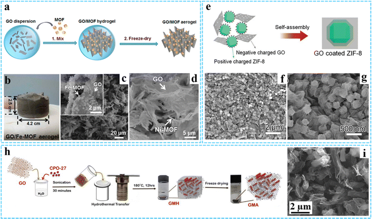 | ||
| Fig. 1 (a) Schematic of the preparation processes for GO/MOF aerogels. (b) Photographs of the GO/Fe-MOF aerogel. SEM images of (c) GO/Fe-MOF and (d) GO/Ni-MOF composite aerogels. Reprinted with permission from ref. 40. Copyright 2017 American Chemical Society. (e) Schematic illustration of the formation process of the hybrid GO/ZIF-8 composite. (f and g) SEM images of the GO/ZIF-8 composite. Reproduced with permission from ref. 46 Copyright 2019 Wiley-VCH. (h) Synthesis process for GMA. (i) SEM image of GMA. Reprinted with permission from ref. 47. Copyright 2021 American Chemical Society. | ||
The physical mixing method is easy to manipulate and realize the combination of graphene and MOFs. Since MOFs are prepared separately, their morphology and size can be effectively controlled. However, the fabrication process may be time-consuming, and the relatively weak interaction between graphene and MOFs makes them tend toward agglomeration. Despite some improvements, more efforts are needed to address this problem.
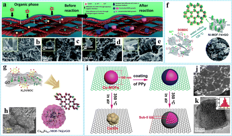 | ||
| Fig. 2 (a) Schematic for the preparation of MOF-PG hybrids. FESEM images of (b) AOGCu(BTC)-PG, (c) AOGZIF67-PG, (d) AOGZIF8-PG, and (e) AOGTM-PG. Reproduced with permission from ref. 60. Copyright 2021 Royal Society of Chemistry. (f) Schematic of the formation process of Ni-MOF-74/rGO. Reproduced with permission from ref. 61. Copyright 2018 Royal Society of Chemistry. (g) Schematic illustration of the synthesis procedure of the Co0.8Fe0.2-MOF-74@rGO hybrid. (h) SEM images of Co0.8Fe0.2-MOF-74@rGO. Reproduced with permission from ref. 64. Copyright 2020 Wiley-VCH. (i) Schematic diagram of the spatially confined pulverization process of Co-MOFs/GO with and without the coating of PPy. (j) SEM image of GCP350. (k) HRTEM images of GCP350, the inset is a histogram of the size distribution of Co-MOFs nanocrystals. Reprinted with permission from ref. 73. Copyright 2018 American Chemical Society. | ||
Hydrothermal/solvothermal treatment is a common method for preparing functional materials, using water/nonaqueous solvent as the solvent and creating a high-temperature and high-pressure environment after heating. During the hydrothermal/solvothermal reaction, the GO is typically reduced to rGO, and then a 3D cross-linked monolithic graphene network can be formed due to π–π stacking interactions and van der Waals forces between the randomly oriented hydrophobic rGO sheets.63 For example, Ren and co-workers prepared a 3D nanoflower-like Co0.8Fe0.2-MOF-74@rGO hybrid (diameter ∼5 μm) via a simple hydrothermal reaction (Fig. 2(g) and (h)).64 Similarly, 3DG/MOF composites with diverse MOF structures have been constructed using such methods, such as GAs-UiO-66-NH2 (UiO-66-NH2 crystals with an octahedral cubic intergrown morphology),65 ADC-rGO (the DMOF-ADC with pillared structure)66 and 3DGS-CuCo-MOF (the Co3.0Cu1.0-MOF with laminated structure)67 and etc. In another study, Wang et al. fabricated highly dispersed UIO-66-NH2 ultrafine nanocrystals in situ grown on graphene (UIO-66-NH2/GR) rapidly with the assistance of a microwave irradiation induced solvothermal route.68 Besides, using 3DG grown on nickel foam (or directly combined with GO) as the scaffold-supported MOF precursor is also an effective way to improve MOF uniformity, which has been widely used in energy storage and conversion fields.69–72
In general, synthesis methods used in the preparation process can not only affect the interaction between MOFs and graphene, but also affect the morphology and properties of the composites. By using conducting polypyrrole (PPy) coated Co-MOFs/GO as precursors, our group successfully fabricated sub-5 nm ultrasmall Co-MOF nanocrystals encapsulated in N-doped carbon/graphene (NC/G) (denoted as GCP350) via a facile thermal-assisted spatially confined pulverization strategy (Fig. 2(i)).73 The GCP350 showed a hierarchical structure with uniformly distributed Co-MOF nanocrystals wrapped by NC/G. The morphology and structure characterization showed that the uniform coating of PPy can significantly improve the decomposition temperature and maintain the component stability of Co-MOFs during calcinations in air, thus leading to the pulverization of bulk Co-MOF particles into ultrasmall nanoparticles (average diameter of ∼4.2 nm) without oxidation (Fig. 2(j) and (k)). Without the coating of PPy, Co-MOF particles would transform into metal oxide.
In situ growth can make MOFs produce uniformly on graphene sheets, which can effectively alleviate the agglomeration of MOF nanocrystals and graphene sheets. However, it is not easy to control the growth of MOFs using this method, and the size of MOF nanocrystals is relatively large due to the rapid coordination reaction between metal ions and ligands.
Excess metal-ion induced in situ growth. Considering the special size-dependent properties, small nanomaterials with remarkable properties have attracted wide attention.74–76 However, the 3DG/MOF composites prepared by the traditional in situ growth method usually produce large MOF nanocrystals due to the rapid coordination reaction. To solve this problem, our group reported a facile and versatile route for fabricating GO/metal cyanide (GO/MC) composites via excess metal-ion induced in situ growth (Fig. 3(a)).77 The experimental results suggested that the excess metal ions were necessary for the successful deposition of MC on GO. The excess metal ions could cover the MC particles and induce the MC particles homogeneity dispersed on GO through coordination interaction and electrostatic attraction and inhibited the overgrowth of MC. In this study, a series of 3DG/MC aerogels such as 3DG/PB, 3DG/Ni–Fe PBA, 3DG/Fe–Co and 3DG/Ni–Ni HCP were successfully obtained by further chemical reduction according to spatially-confined Ostwald ripening. It can be seen that the size of PB nanoparticles before and after adding the sodium ascorbate was around 20 nm and 40–80 nm, respectively (Fig. 3(b) and (c)).
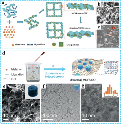 | ||
| Fig. 3 (a) A schematic illustrating the preparation of the 3DG/MC aerogels. (b) and (c) SEM images of the 3DG/PB aerogel. Reproduced with permission from ref. 77. Copyright 2017 Wiley-VCH. (d) Schematic illustration of the synthesis procedure of ultrasmall MOFs/RGO. (e) SEM and (f and g) TEM images of the PB/GO aerogel. Reproduced with permission from ref. 78. Copyright 2020 Wiley-VCH. | ||
Based on the universality and adjustability of this method, a series of ultrasmall PB or PBA nanoparticles (average size <10 nm) uniformly grown on the GO surface have been reported by us through a modified excessive metal-ion induced self-assembly route (Fig. 3(d)).78 The resulting PB/GO and PBAs/GO aerogels could be further obtained by freeze-drying. SEM and TEM images shown in Fig. 3(e)–(g) indicate that the average size of the PB nanoparticles was 5.2 nm. Moreover, other ultrasmall PBA nanoparticles, such as Ni–Ni PBA, Ni–Fe PBA, Fe–Co PBA, and FeNi–Co PBA with an average size below 10 nm could also be obtained. Particularly, we have also successfully synthesized other 3DG/MOF composites with a unique structure and excellent properties by using this method.76,79–83
In recent years, many 3DG/MOF-based composites have been prepared by direct physical mixing or in situ growth, but the choice of MOFs is usually the existing common types, such as the ZIF, MIL and UiO series. Therefore, the variety of MOFs can be expanded by selecting other metal ions and organic ligands. Although the combination of MOFs and graphene can make up for the poor conductivity of MOFs, it will also lose the advantage of MOFs in structural diversity to a certain extent. Thus, the development of new conductive MOFs has broad application prospects.
2.2 3DG/MOF-derived composites
In addition to 3DG/MOF composites, different kinds of nanosized materials including carbon, metal nanocrystals, and metal compounds (metal oxides, metal sulfides, metal phosphides, etc.) derived from MOFs can be introduced into the 3DG to form the hybrids with various morphologies and advanced properties, which are described in the following section.Jiao and co-workers firstly synthesized a novel MOF–rGO composite consisting of a nickel-based pillared MOF (DMOF-ADC) and rGO via a simple solvothermal method.66 In the subsequent step, ADC-C/rGO was prepared by further thermal treatment at 600 °C in N2 and using the concentrated HCl to remove nickel residues, which could be effectively used as the negative electrode material for hybrid supercapacitors (Fig. 4(a)). Morphology and structure characterization indicated that the as-prepared ADC-C/rGO retained a similar morphology to ADC-rGO, and the graphene sheets were uniformly coated on the hollow microrods (Fig. 4(b)). In another study, Wang et al. prepared Co, N-codoped porous carbon nanocage anchored 3D graphene framework (Co/N-PCN@rGO) aerogel composites by calcination of ZIF-67@rGO precursor and subsequent partial acid-etching.59 The ZIF-67 dodecahedron could be transformed into a hollow structure under thermal-induced stress and decomposition. By further HCl (1 M) etching treatment, some Co nanoparticles could be removed, leaving more pores in the system (Fig. 4(c)–(e)). The construction of a porous structure facilitated the penetration of electrolyte, and the strong coupling between Co/N-PCN and rGO was conducive to electron transfer and mechanical stability.
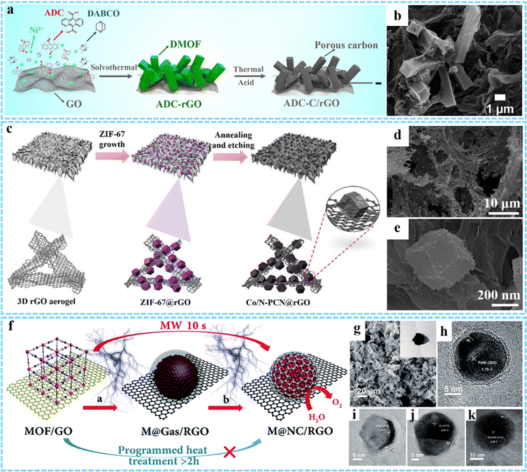 | ||
| Fig. 4 (a) Illustration of the synthesis process of ADC-C/rGO. (b) SEM image of ADC-C/rGO. Reprinted with permission from ref. 66. Copyright 2019 American Chemical Society. (c) Synthesis procedures for Co/N-PCN@rGO. (d and e) FESEM images of the Co/N-PCN@rGO composites. Reprinted with permission from ref. 59. Copyright 2020 Elsevier. (f) Synthesis process for M@NC/RGO. (g) SEM image of FeNi@NC/RGO. HRTEM images of (h) FeNi@NC/RGO, (i) CoNi@NC/RGO, (j) Co@NC/RGO and (k) FeCoNi@NC/RGO. Reproduced with permission from ref. 75. Copyright 2018 Royal Society of Chemistry. | ||
It is well known that the presence of metals can increase the number of active sites and enhance electrical conductivity.87 When combined with graphene, it shows good activity and excellent stability, and can maintain catalytic activity under strong acidic or alkaline conditions. Considering this, our group has developed a novel, general and ultrafast microwave-assisted thermal conversion strategy, and for the first time prepared a series of M@NC/RGO (FeNi@NC/RGO, CoNi@NC/RGO, Co@NC/RGO, and FeCoNi@NC/RGO) composites by changing the composition of MOF (Fig. 4(f)).75 This microwave-assisted method broke down the MOF into separate metals and carbon- and nitrogenous gases at the initial thermal conversion stage, rather than producing aggregated metal and carbon composites as conventional heat treatments were carried out, thus effectively controlling the formation of carbon on the metal surface. Finally, uniformly dispersed core@shell M@NC nanocrystals could be formed on graphene sheets, and the averaged size of FeNi@NC, CoNi@NC, Co@NC, and FeCoNi@NC was about 20 nm, 20 nm, 20 nm and 19 nm, respectively (Fig. 4(g)–(k)).
3DG/MOF-derived metal oxides. Using 3DG/MOF composites as precursors, 3DG/MOF-derived metal oxides can be fabricated via two-step thermal treatment. Some 3DG/MOF-derived metal oxides (e.g., N-Co3O4@N-C/rGO-S,90 ZnO/3DGN and Fe2O3/3DGN,69 Co3O4/3DGN/NF91) were produced using this strategy. As an example, Zhu and co-workers prepared a HoCo3O4/NS-RGO composite with hollow Co3O4 nanoparticles embedded in a N,S co-doped rGO framework (Fig. 5(a) and (b)).92 Firstly, the presynthesized Co-MOF/GO precursor was annealed at 800 °C for 2 h in Ar to obtain the Co@ Co3O4/NS-RGO, and the Co@Co3O4 possessed a core–shell-like structure with an average diameter of 10–18 nm. Then the resultant HoCo3O4/NS-RGO composite could be achieved via further annealing the Co@ Co3O4/NS-RGO in 250 °C air for 2 h. Besides, the corresponding derived metal oxides can also be prepared through a one-step carbonization process in an inert gas.54,93
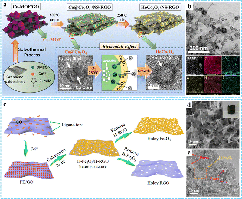 | ||
| Fig. 5 Schematic of the synthesis process of the HoCo3O4/NS-RGO framework. (b) TEM and HAADF images of the HoCo3O4/NS-RGO, along with the corresponding elemental mapping images. Reprinted with permission from ref. 92. Copyright 2020 American Chemical Society. (c) Synthesis procedures for the H-Fe2O3/H-RGO heterostructure. (d) SEM and (e) HRTEM images of H-Fe2O3/H-RGO. Reprinted with permission from ref. 74. Copyright 2018 American Chemical Society. | ||
Compared with two-step calcination, one-step calcination in air can effectively shorten the reaction path.70,94–96 An interesting advance is that our group synthesized a double-holey-heterostructure with the holey Fe2O3 nanosheets (H-Fe2O3) tightly grown on the holey reduced graphene oxide (H-RGO) by using PB/GO aerogel as the precursor via annealing in air (Fig. 5(c) and (d)).74 TEM results indicated that the continuous holey H-Fe2O3 nanosheets were formed through chemically interconnecting the ultrasmall Fe2O3 nanoparticles (average diameter ∼5 nm) that were generated during the annealing process (Fig. 5(e)). Meanwhile, H-RGO with many nanopores was produced through the thermal reduction of GO, leading to the thermal degradation of the defective domains on GO. The as-obtained H-Fe2O3/H-RGO exhibited a high specific surface area of 280 m2 g−1, and the abundant nanopores and highly continuous 3D framework allowed for the rapid transfer of ions and electrons when used as an anode for LIBs. By annealing the presynthesized 3DG/PB aerogel at 250 °C for 2 h in air, we successfully fabricated 3DG/Fe2O3 aerogel with a porous structure of Fe2O3 evenly wrapped within the graphene framework, which was used as the anode for LIBs.79
3DG/MOF-derived metal sulfides. Metal sulfides are widely used in the electrochemical field because of their strong conductivity and high specific capacity. The synthesis of metal sulfides using 3DG/MOF composites as the precursor is an effective measure to improve the electrochemical properties, which can not only improve the connectivity between metal sulfides, but also shorten the transport path of ions in the electrolyte path.33 As a simple and convenient method, 3DG/MOF-derived metal sulfides can be prepared by hydrothermal/solvothermal vulcanization reaction, in which thiourea and thioacetamide (TAA) can be used as sulfur sources.42,92 He and co-workers successfully prepared Co9S8-3DGF composites through a three-step process, including the growth of graphene on nickel foam via chemical vapor deposition (CVD), in situ growth of MOF on graphene foam, and solvothermal reaction of MOF-3DGF with TAA (Fig. 6(a)).94 SEM images suggested that Co9S8-3DGF with a hollow structure was formed after TAA vulcanization, mainly attributing to the Kirkendall effect (Fig. 6(b)–(d)). Jiang et al. designed and prepared a 3D CoS2QDs@rGO composite via a two-step hydrothermal method followed by a one-step calcination method, and was used as an efficient catalyst for the hydrogen evolution reaction (HER).50
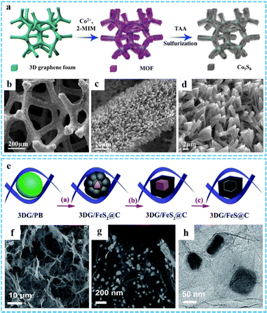 | ||
| Fig. 6 (a) Schematic illustration of the synthetic route of the Co9S8-3DGF composites. (b)–(d) SEM images of Co9S8-3DGF. Reprinted with permission from ref. 94. Copyright 2018 Elsevier. (e) Illustration of the synthesis process of the 3DG/FeS@C composites. (f) and (g) SEM and (h) TEM of DG/FeS@C. Reproduced with permission from ref. 81. Copyright 2018 Royal Society of Chemistry. | ||
It is an effective method to synthesize metal sulfides by directly calcining the mixture of MOFs and sulfur-containing materials. Inspired by this, using the pre-prepared 3DG/PB aerogel as the precursor, our group designed a new flexible 3DG/FeS@C nanocomposite through one-step thermal conversion after mixing with sulfur powder (Fig. 6(e)).81 As shown in Fig. 6(f)–(h), the core–shell FeS@C nanocomposite was encapsulated in the 3DG framework, which was formed in the process of sulfur heat treatment derived from 3DG confined phase separation of the metal and organic moieties of PB. The robust 3D porous conductive network together with the core@shell structure and N and S co-doping, which could be directly and effectively used as an anode for sodium-ion batteries (SIBs). Our other work we also successfully prepared FeS2/PNC@3DG composites using this method.76 In addition, other 3DG/MOF-derived metal sulfides have been prepared by one-step thermal conversion using sulfur powder or thiourea as sulfur sources.61,62,97
3DG/MOF-derived metal phosphides. Due to their high theoretical capacity and activity, metal phosphides have a broad application prospect in the field of electrochemistry.98 3DG/MOF-derived metal phosphides have been shown to be one of the most effective strategies to remarkably enhance the electrochemical performance. Different from 3DG/MOF-derived metal sulfides, 3DG/MOF-derived metal phosphides usually choose NaH2PO2 as the phosphorus source and can be obtained by one-step calcination in an inert atmosphere.45,99 For instance, Zhao et al. proposed a hierarchical micro/nanostructured hybrid composed of rGO sheets and porous N-doped carbon nanowires constrained CoP nanocrystals (average size ∼5.1 nm).100 Zhang et al. prepared 3DG/FeP aerogel composites using a spatially confined one-step thermal conversion strategy (Fig. 7(a) and (b)).101 The FeP nanospheres derived from MOF had hollow structures with an average size of ∼50 nm and were evenly coated in graphene sheets (Fig. 7(c) and (d)). Differently, our group have developed a novel ultrafast microwave assisted thermal conversion method and successfully constructed bimetallic phosphide/graphene composites with adjustable heterostructures (Fig. 7(e)).82 Using NaH2PO2 as the phosphorus source, the phosphating reaction of MOF on graphene sheets could be achieved within 20 s under microwave radiation. Through this method, we not only achieved P-doping in graphene to obtain FeNiP/PG composites, but also induced the generation of GC on FeNiP to prepare FeNiP/GC/PG composites, which was very different from traditional heat treatment method (Fig. 7(f) and (h)). The as-obtained FeNiP and FeNiP/GC nanocrystals with an average size of 10 nm and 22 nm were uniformly dispersed on the graphene sheets (Fig. 7(g) and (i)).
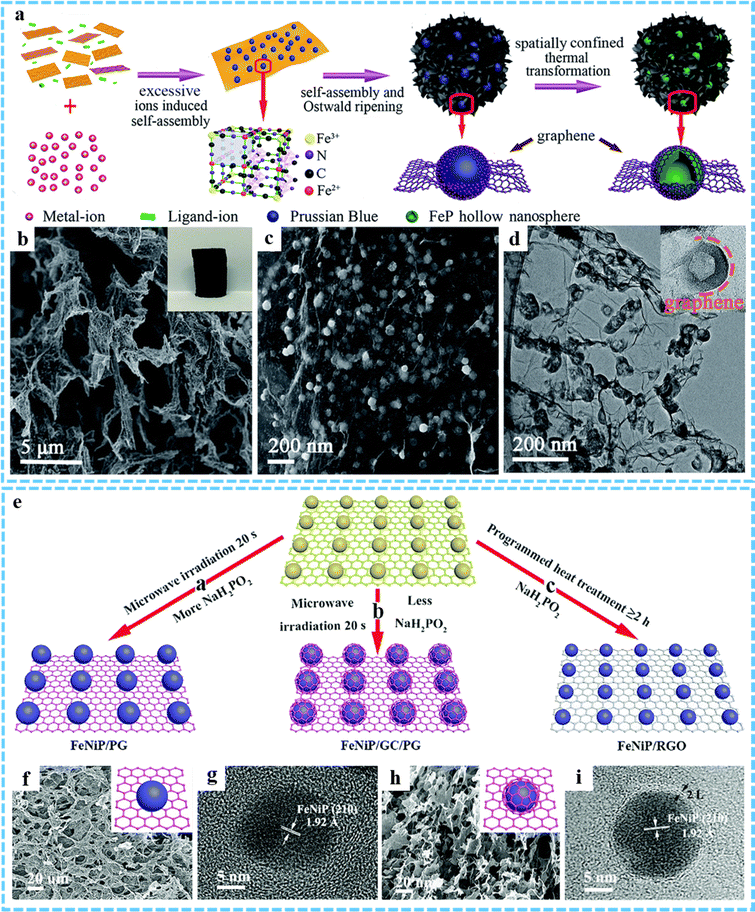 | ||
| Fig. 7 (a) Synthesis procedures for the 3DG/FeP composite aerogel. (b and c) SEM and (d) TEM images of 3DG/FeP. Reproduced with permission from ref. 101. Copyright 2020 Royal Society of Chemistry. (e) Schematic of the synthetic process of FeNiP/PG, FeNiP/GC/PG and FeNiP/RGO composites. (f) SEM and (g) HRTEM images of FeNiP/PG. (h) SEM and (i) HRTEM images of FeNiP/GC/PG. Reproduced with permission from ref. 82. Copyright 2019 Royal Society of Chemistry. | ||
3DG/MOF-derived other metal compounds. Due to the variety of metal ions and organic ligands available for MOFs, other MOF-derived metal compounds, such as metal selenides, metal carbides, metal nitrides, etc., can also be prepared by high temperature pyrolysis or other strategies. In order to fabricate the anode for LIBs with excellent performance, we used a 3DG/MOF aerogel as the precursor and subsequently prepared a 3DG/Fe7Se8@C composite by calcination with Se powder at 600 °C in Ar/H2.80 By using microwave-assisted induced thermal transformation of the PB/GO aerogel, our group achieved the decomposition and transformation of PB to core–shell Fe3C@C nanoparticles (average size 18 nm) and the reduction of GO to rGO (Fig. 8(a)–(d)).78 However, under traditional heating conditions, only large and partially aggregated iron/carbon complex (FexC) nanoparticles (average size ∼50 nm) could be obtained. In addition, transition metal nitrides (TMNs) have received great attention as electrocatalysts due to their wide range of material types and adjustable surface properties. Using ZIF-67/graphene aerogel (ZIF-67/GA) as a template, Zou and co-workers fabricated a CoNx/NGA hybrid through thermal treatment at 500 °C in an ammonia atmosphere (Fig. 8(e)–(i)).52 Due to the abundant active sites of amorphous CoNx nanoparticles and the 3D porous conductive network structure of NGA, the resultant CoNx/NGA exhibited excellent electocatalytic activity and stability in the ORR, OER and HER.
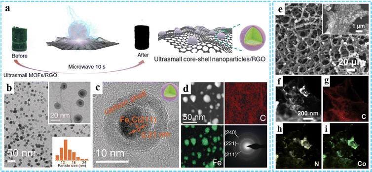 | ||
| Fig. 8 (a) Schematic illustration of the fabrication process of Fe3C@C/RGO. (b) TEM and (c) HRTEM images of Fe3C@C/RGO. (d) STEM image, element mapping and SAED pattern. Reproduced with permission from ref. 78 Copyright 2020 Wiley-VCH. (e) SEM image of CoNx/NGA. (f) HAADF and (g)–(i) EDXS images of CoNx/NGA. Reprinted with permission from ref. 52. Copyright 2019 Elsevier. | ||
So far, a large number of 3DG/MOF-derived composites with complex composition, structure and function have been successfully prepared by high temperature heat treatment. However, the commonly used types of MOFs are still limited. Thus, it is necessary to explore other efficient MOFs as precursors to expand the diversity of MOF derivatives, along with systematically studying the relationship between the properties and structures of MOF-derived materials, which can further guide the design and synthesis of high-performance 3DG/MOF-derived composites. Moreover, most MOF-derived materials need to be calcined at high temperature. Although the 3DG network structure is conducive to the stability of the system, the porous structure can easily be destroyed. Therefore, reasonable reduction of the calcination temperature is also very important for the preparation of high-performance 3DG/MOF-derived composites.
3. Application of 3DG/MOF composites and their derivatives to electrochemical energy storage and conversion
MOFs are known to have high porosity, a large surface area, as well as flexible design and componential diversity, but their poor conductivity and stability limit their wide application in energy storage and conversion. As a typical carbon material, graphene has high electrical conductivity and stability, but graphene sheets tend to aggregate easily. Therefore, combining MOFs with graphene to construct MOF/graphene-based composites can improve their existing problems, so as to synergically promote the electrochemical performance of the system. In this section, we mainly review the applications of 3DG/MOF composites and their derivatives in batteries, SCs and electrocatalysis.3.1 Batteries
With the rapid development of new energy industries, the development of high-capacity, low-cost and environmentally friendly rechargeable batteries has attracted much attention. As a typical inorganic–organic nanomaterial, MOFs have been widely studied in the construction of battery electrodes due to their special characteristics of large porosity, adjustable structure and abundant active sites.102 To meet the demand for high performance battery electrode materials, studies have shown that combining MOFs with graphene-based conductive materials can significantly improve the capacity, electronic conductivity and stability of the system.103 At present, many researchers have reported the design and synthesis of 3DG/MOF composites and their derivatives with excellent physical and chemical properties for LIBs, SIBs, potassium ion batteries (PIBs) and lithium–sulfur batteries (LSBs) electrode materials.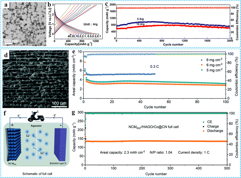 | ||
| Fig. 9 (a) TEM image of GCP350. (b) Charge–discharge curves of GCP350 at different current densities. (c) Cycling performance of GCP350. Reprinted with permission from ref. 73. Copyright 2018 American Chemical Society. (d) The cross-sectional SEM image of HAGO/Co@CN. (e) Areal capacity of the HAGO/Co@CN electrodes at 0.3C. (f) Schematic diagram of the NCM622//HAGO/Co@CN full cell. (g) Long-term cycle performance of the NCM622//HAGO/Co@CN full cell. Reproduced with permission from ref. 43. Copyright 2022 Royal Society of Chemistry. | ||
Based on the excellent structural characteristics of porous and hollow metal oxides derived from MOFs, we designed and synthesized 3DG/Fe2O3 composites with porous Fe2O3 nanoframeworks,79 double holey H-Fe2O3/H-RGO heterostructure with holey Fe2O3 nanosheets,74 and S-H-Fe2O3/RGO composites with ultrasmall hollow Fe2O3 nanoparticles78 as high performance anodes for LIBs. In addition, many other 3DG/MOF-derived metal compounds (e.g., 3DG/Fe7Se8@C,80 HoCo3O4/NS-RGO,92 Fe3O4@C/RGO,93 NC@CoOx@GF,95 PGF@pFe2O3 NF,96 HAGO/Co@CN43) have been constructed for LIB electrode materials. For example, Wang et al. reported a ZIF-67-derived Co@CN modified horizontally aligned GO array (HAGO/Co@CN) as an independent anode for LIBs.43 The cross-sectional SEM image showed that the HAGO/Co@CN had a layered porous and highly interpenetrating network structure (Fig. 9(d)). And this unique structure exhibited excellent structural stability and electrochemical performance, which could achieve stable cycling at a high area capacity of 5 mA h cm−2 (Fig. 9(e)). In addition, they constructed a full cell with HAGO/Co@CN as the anode and NCM622 as the cathode, exhibiting an ultrahigh capacity of 2.3 mA h cm−2 at 1 C and a high capacity retention rate (>98%) after 500 cycles (Fig. 9(f) and (g)).
Based on the unique advantages of MOFs and graphene, 3DG/MOF-based composites have potential advantages.45,62,81 Inspired by this, we synthesized a free-standing 3DG/PB aerogel to be used as a cathode material for SIBs, with an excellent rate performance and long-term cycling stability.77 The remarkable electrochemical properties of the 3DG/PB aerogel derived from their 3D porous conductive frameworks and the special RGO/PB/RGO sandwich structure, resulting in effective electron and ion transport, as well as structural stability. In addition, 3DG/MOF-derived metal compounds have shown great potential in SIBs. Our group explored a multi-scale nanostructured FeS2/PNC@3DG composite anode using a simple one-step vulcanization strategy.76 The SEM and TEM results showed that the ultrafine FeS2 nanocrystals were separated and protected by porous nitrogen-doped carbon nanospheres (PNCS) and uniformly encapsulated in 3DG (Fig. 10(a) and (b)). The unique multi-scale nanostructure of FeS2/PNC@3DG could increase the active sites, shorten the ion diffusion path, and accelerate the electron/ion transport. Thus, it displayed excellent electrochemical properties, possessing an ultra-high reversible capacity of 597 mA h g−1 at 0.2 A g−1 (Fig. 10(c)), superior rate capacity of 316 mA h g−1 at 5 A g−2 (Fig. 10(d)), and excellent long-term cycling performance with a capacity retention of 85.2% after 800 cycles (Fig. 10(e)). Theoretical calculations suggested that the presence of NC not only improved the conductivity of FeS2, but also provided enhanced Li/Na interface storage. Using ZIF-67-GO-NF as the precursor, Ge et al. prepared CoP@C-RGO-NF architectures through a low temperature phosphatizing process, in which the porous core/shell CoP@C polyhedron structures derived from ZIF-67 were uniformly anchored onto the 3D RGO-NF network (Fig. 10(f)).99 Due to the synergistic effect of porous core/shell structured CoP@C and RGO networks, the specific capacity of CoP@C-RGO-NF as the anode for SIBs could reach 473.1 mA h g−1 after 100 cycles at 100 mA g−1, which also showed an excellent reversible capability (Fig. 10(g) and (h)).
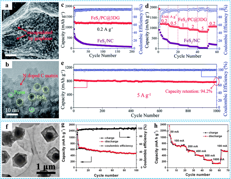 | ||
| Fig. 10 (a) TEM and (b) HRTEM images of the FeS2/PNC@3DG aerogel. (c) Cycling performance of the FeS2/PNC@3DG and FeS2/NC anode at 0.2 A g−1 for 200 cycles. (d) Rate capabilities of the FeS2/PNC@3DG and FeS2/NC anodes, respectively. (e) Cycling performance of the FeS2/PNC@3DG at 5 A g−1 for 1000 cycles. Reproduced with permission from ref. 76. Copyright 2019 Royal Society of Chemistry. (f) TEM image of CoP@C-RGO. (g) Cycling performance and coulombic efficiency of the CoP@C-RGO-NF anode at 100 mA g−1. (h) Rate capability of the CoP@C-RGO-NF anode. Reprinted with permission from ref. 99. Copyright 2017 Elsevier. | ||
PIBs have a higher energy density than SIBs due to the lower reduction potential of K, but the large K+ radius makes the K+ reaction kinetics in PIBs slow and the rate performance is not ideal.35 The construction of porous 3D network electrode materials is considered to be an effective strategy. Our group prepared a Co-MOF-rGO hybrid by using an effective interface engineering strategy, which was employed as the free-standing anode for PIBs (Fig. 11(a)).83 The strong chemical coupling between Co-MOF and rGO calculated by DFT could improve the adsorption and diffusion of the potassium ion within Co-MOF nanocrystals, rending the Co-MOF-rGO anode with an ultrahigh reversible capacity of 422 mA h g−1 at 0.1 A g−1, outstanding rate capability of 202 mA h g−1 at 5 A g−1, and excellent prolonged cycling performance of 74% capacity retention after 2000 cycles at 2 A g−1, much better than the physical composite Co-MOF/rGO (Fig. 11(b)–(e)). Transition metal phosphides (TMP) have been regarded as promising anode materials for PIBs due to their high theoretical capacity and excellent thermodynamic stability. Using 3DG/MOF as a precursor, Zhang and co-workers constructed a layered porous 3DG/FeP aerogel composite through a spatially confined thermal conversion strategy, in which FeP hollow nanospheres were uniformly encapsulated in the 3DG skeleton (Fig. 11(f)).101 The electrochemical measurement results showed that the flexible 3DG/FeP film obtained by simple compression of 3DG/FeP aerogel as the anode had a high reversible capacity (323 mA h g−1 at 0.1 A g−1) and remarkable electrochemical stability (97.6% capacity retention at 2 A g−1 after 2000 cycles) (Fig. 11(g)–(i)).
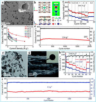 | ||
| Fig. 11 (a) TEM image of the Co-MOF-rGO hybrid. (b) The charge density difference of the Co-MOF-rGO hybrid. (c) Rate capability of the Co-MOF-rGO and Co-MOF/rGO anodes. (d) Comparison of the Co-MOF-rGO hybrid and other representative anodes of PIB. (e) Long-term cycling performance of Co-MOF-rGO hybrid anodes at 2 A g−1 over 2000 cycles. Reprinted with permission from ref. 83. Copyright 2020 American Chemical Society. (f) TEM image of 3DG/FeP. (g) SEM image of the side-view of the pressed 3DG/FeP film, the inset is the photograph of the flexible 3DG/FeP film. (h) Rate performance of 3DG/FeP and FeP. (i) Cycling performance of 3DG/FeP at 2 A g−1 for 2000 cycles. Reproduced with permission from ref. 101. Copyright 2020 Royal Society of Chemistry. | ||
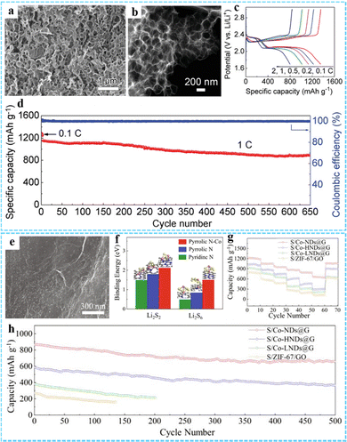 | ||
| Fig. 12 (a) SEM and (b) STEM images of the PCF. (c) Galvanostatic charge/discharge profiles of the PCF/S electrode at the current densities from 0.1 C to 2 C. (d) The prolonged cycling performance of the PCF/S electrode at 1 C. Reproduced with permission from ref. 46 Copyright 2019 Wiley-VCH. (e) SEM image of Co-NDs@G. (f) Binding energy and optimized structure of Li2S2 and Li2S6 on Pyridinc N, Pyrrolic N and Pyrrolic N–Co. (g) Multi-rate cycling of cells with the S/Co-NDs@G cathode under raised sulfur loadings. (h) Cycling performance of the Li–S battery at 1C with different cathodes. Reprinted with permission from ref. 87. Copyright 2021 Elsevier. | ||
3.2 Supercapacitors
As another promising energy storage device, SCs are attracting more and more attention because of their advantages including high power density, fast charging and discharging speed and long cycle life.109,110 According to the energy storage mechanisms, SCs can be classified into two types: electric double-layer capacitors (EDLCs) that derive from charge separation at the electrode/electrolyte interface and pseudocapacitors that store charge through reversible redox reactions involving the surface region of the electrode material.111 Generally, EDLCs are composed of carbon-based electrode materials, such as porous carbon, carbon nanotubes and graphene, which exhibit a high power density, long cycle life due to their high specific surface area, controllable porosity, good electron conductivity and so on, but their energy density is low.112 Conductive polymers and metal compounds are commonly used as pseudocapacitive electrode materials due to their rapid reversible redox reactions, which exhibit higher capacity and energy density.113 However, their cycle stability is relatively poor and their power density is low. Therefore, thanks to the large specific surface area and potential pseudocapacitor sites of MOFs, as well as electric double-layer capacitance provided by graphene, 3DG/MOF composites have been proven to be highly suitable for using as the SCs electrodes.41,55 Barua and co-workers prepared a GMA electrode material for supercapacitors without any binder and conductive additive (Fig. 13(a)).47 The GMA exhibited excellent specific capacitance properties at both low mass loads of 3 mg cm−2 (98 F g−1 at 0.5 A g−1) and high mass loads of 10 mg cm−2 (75 F g−1 at 0.5 A g−1) (Fig. 13(b)). In particular, the GMA electrode showed excellent stability of 100% after 25![[thin space (1/6-em)]](https://www.rsc.org/images/entities/char_2009.gif) 000 cycles under both conditions (Fig. 13(c) and (d)). Moreover, Hong et al. used a facile one-pot solvothermal method to synthesize a Ni–Co-MOF/GO composite with a 3D structure, and the material used as the capacitor electrode exhibited a high energy storage performance.56
000 cycles under both conditions (Fig. 13(c) and (d)). Moreover, Hong et al. used a facile one-pot solvothermal method to synthesize a Ni–Co-MOF/GO composite with a 3D structure, and the material used as the capacitor electrode exhibited a high energy storage performance.56
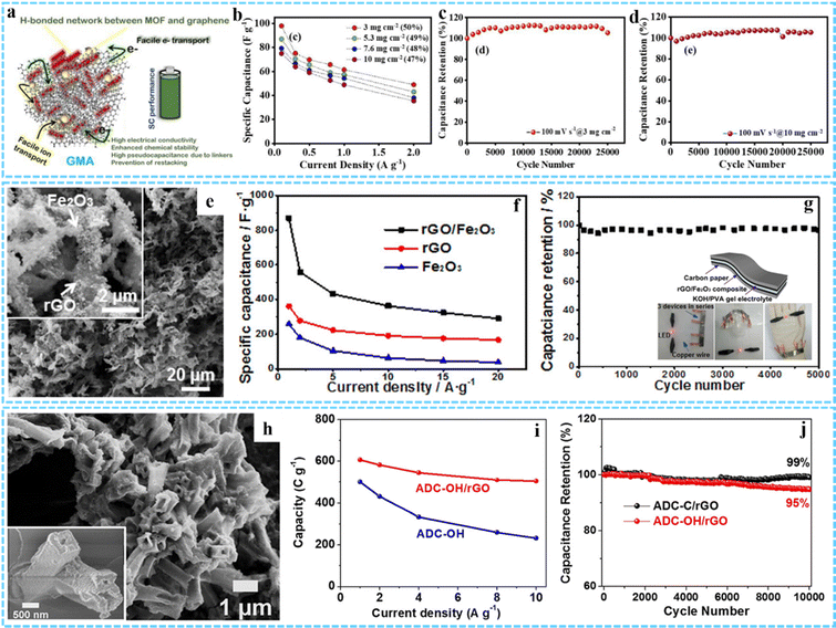 | ||
| Fig. 13 (a) Schematic illustration of the excellent performance of GMA as a supercapacitor. (b) The specific capacitance retention of GMA at different mass loadings with current density. Cycling performance of GMA at (c) 3 mg cm−2 and (d) 10 mg cm−2. Reprinted with permission from ref. 47. Copyright 2021 American Chemical Society. (e) SEM image of the rGO/Fe2O3 composite aerogel. (f) Specific capacitance of rGO/Fe2O3, rGO, and Fe2O3 at different current densities. (g) Long-term cycling performance of the flexible all-solid state supercapacitor based on the rGO/Fe2O3 composite. Inset: Schematic diagram of the flexible all-solid state supercapacitor device and the photographs of a red LED lit by a tandem cell. Reprinted with permission from ref. 40. Copyright 2017 American Chemical Society. (h) SEM image of ADC-OH/rGO. (i) Rate performance of ADC-OH and ADC-OH/rGO. (j) Long-term cyclic stability test of ADC-OH/rGO and ADC-C/rGO at 20 A g−1. Reprinted with permission from ref. 66. Copyright 2019 American Chemical Society. | ||
Various 3DG/MOF-derived composites have also been employed as promising high-performance SC electrodes, such as Co3O4/3DGN/NF,91 3DGN/Mn2O3,114 CoOx/NG-A and C/NG-A,51 Co1−xS/CoFe2O4@rGO,64 R-NiS/rGO,61 Co/Zn–S@rGO,42 3D ZnCo2O4/GA and 3D N-AC/GA,115 and so on. In a typical case, Xu and co-workers prepared a rGO/Fe2O3 aerogel composite through simple freeze-drying and calcination processes of the GO/Fe-MOF composite aerogel precursor (Fig. 13(e)).40 The specific capacitance of the rGO/Fe2O3 electrode reached 869.2 F g−1 at 1 A g−1, which was much higher than that of rGO (360.8 F g−1) and Fe2O3 (258.5 F g−1) (Fig. 13(f)). When used as a flexible all-solid state supercapacitor, it had a high capacity capacitance and good stability (96.3% capacity retention rate after 5000 cycles) (Fig. 13(g)). The excellent electrochemical performance was mainly due to the 3D framework structures formed by interconnected rGO sheets and the synergistic effect between rGO and Fe-MOF-derived Fe2O3 nanostructures. Porous nitrogen-rich carbon and Ni(OH)2 derived from ADC were uniformly anchored on rGO sheets to be used as the negative electrode and positive electrode for SCs individually, as proposed by Jiao and co-workers (Fig. 13(h)).66 The hybrid device exhibited a high rate capability of 608 C g−1 at 1 A g−1 and a capacity loss of 5% after 10![[thin space (1/6-em)]](https://www.rsc.org/images/entities/char_2009.gif) 000 cycles at 20 A g−1 (Fig. 13(i) and (j)).
000 cycles at 20 A g−1 (Fig. 13(i) and (j)).
3.3 Electrocatalysis
Electrocatalysis, as an efficient energy storage and conversion technology, is an important way to achieve sustainable clean energy in the future, among which the HER, oxygen evolution reaction (OER) and oxygen reduction reaction (ORR) are several important reactions in electrochemical energy conversion devices. It is well known that platinum-based materials have excellent electrocatalytic activity, but their high price and low stability limit their commercial application.37 Therefore, it is urgent to develop low cost and high performance non-precious metal catalysts. In recent years, 3DG/MOF-based composites have been widely used in the field of electrocatalysts due to their abundant pore structure, large specific surface area, abundant active sites and strong designability.![[thin space (1/6-em)]](https://www.rsc.org/images/entities/char_2009.gif) 000 s. There are also many other 3DG/MOF composites that have been used as electrocatalysts for the OER, such as MFN@GA/NF,71 Co0.3Ni0.7-MOF/3DG/NF8,72 3D Gr/Ni-MOF,57 MOF-PG,60 and so on.
000 s. There are also many other 3DG/MOF composites that have been used as electrocatalysts for the OER, such as MFN@GA/NF,71 Co0.3Ni0.7-MOF/3DG/NF8,72 3D Gr/Ni-MOF,57 MOF-PG,60 and so on.
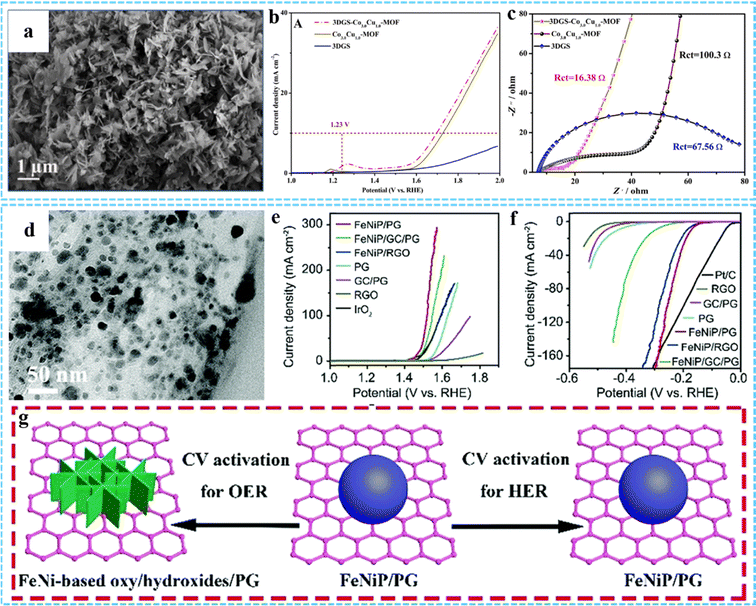 | ||
| Fig. 14 (a) SEM image of 3DGS-Co3.0Cu1.0-MOF. (b) LSV curves and (c) EIS of 3DGS, Co3.0Cu1.0-MOF, and 3DGS-Co3.0Cu1.0-MOF. Reprinted with permission from ref. 67. Copyright 2021 Elsevier. (d) TEM image of FeNiP/PG. iR-corrected polarization curves of various samples for the (e) OER and (f) HER, respectively. (g) Illustration of morphological changes after the CV activation process of FeNiP/PG for the OER and HER. Reproduced with permission from ref. 82. Copyright 2019 Royal Society of Chemistry. | ||
3DG/MOF-derived composites with a unique multilevel network structure, abundant active sites and excellent electrical conductivity can be used as HER and OER electrocatalysts.36,50,52 Compared with traditional programmed heat treatment, microwave-assisted thermal conversion offers many possibilities for the preparation of novel 3DG/MOF-derived composites. Using this approach, our group successfully constructed uniformly dispersed monolayer/few-layer N-doped graphene encapsulated metal nanocrystals for efficient electrocatalytic OER.75 In our other work, we used this method to prepare bimetal phosphide/P-doped graphene (FeNiP/PG) as a bifunctional catalyst for both the OER and HER (Fig. 14(d)).82 The electrochemical results indicated that FeNiP/PG had low overpotential for the OER (229 mV) and HER (173 mV) at 10 mA cm−2 in 1 M KOH solution (Fig. 14(e) and (f)). The morphology of FeNiP/PG did not change significantly during the CV activation process (Fig. 14(g)). Its excellent overall water splitting properties were mainly due to the synergistic effect between FeNiP and PG. The uniformly dispersed FeNiP nanocrystals could provide abundant active sites, and P-doping in graphene could further improve its OER and HER properties.
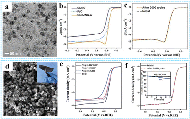 | ||
| Fig. 15 (a) TEM image of the CoOx/NG-A composite. (b) ORR polarization curves of CoOx/NG-A at 10 mV s−1 and 1600 rpm. (c) Cycling performance of CoOx/NG-A. Reprinted with permission from ref. 51. Copyright 2017 American Chemical Society. (d) Top-view SEM image of Ni@N-HCGHF. (e) LSV curves for the ORR of various samples. (f) Cycling performance of Ni@N-HCGHF over 2000 CV cycles. Reproduced with permission from ref. 121 Copyright 2020 Wiley-VCH. | ||
4. Conclusions and prospects
3DG/MOF-based materials with a unique hierarchical porous structure are of great significance to realize high-performance applications in the field of electrochemistry. In this feature article, we first discussed the latest synthesis methods for constructing 3DG/MOF composites (such as physical mixing and in situ growth) and 3DG/MOF derivatives. Then, their applications in electrochemical energy storage and conversion fields such as batteries, SCs and electrocatalysis were elaborated in detail.Although great progress has been made in the preparation and application of 3DG/MOF-based composites recently, there are still some aspects to be further improved and developed. First, currently, the reported types of MOFs are limited, mainly concentrated on ZIF series, MIL series, UiO series and HKUST-1 series. By regulating their composition and structure, more optimized MOFs and their derivatives can be obtained. In addition, other functional MOF-based materials, such as conductive MOFs, have potential advantages in the field of electrochemical applications. Second, for 3D porous materials, the construction of a hierarchical pore structure can simultaneously improve the specific surface area, the number of electrochemical active sites and the efficiency of ion/electron transport. Although 3DG/MOF-based composites exhibit a porous structure, it is difficult to precisely adjust the porous structure, especially for micropores and mesopores. Thus, the preparation of ordered porous 3DG/MOF composites and their derivatives is worth studying. Third, it is well known that strong interaction, coordination effect, synergistic effect and confinement effect at the interface have an important influence on electrochemical activity and stability. However, the interface interaction between MOFs and graphene is weak. Usually, electrostatic interactions between simple physically mixed MOFs and graphene is enhanced by means of surface modification, and covalent interactions between groups on GO and groups on MOF ligands can be enhanced by in situ growth. However, there is competition between oxygen-containing groups on GO and organic ligands on MOFs for the binding of metal cations, which will affect the formation of MOFs. Thus, it is essential to explore 3DG/MOF-based materials with strong interfacial interaction to improve the electrochemical performance. We proposed a facial and versatile strategy for uniform in situ growth of MOFs induced by excessive metal ions anchored on the GO surface, which can be extended to the synthesis of other 3DG/MOF-based materials as high performing electrode materials. Fourth, the size and structure of nanomaterials have significant influence on their electrochemical activity. Smaller and monodisperse nanomaterials can provide more active sites, thus promoting the improvement of electrochemical performance. As is known, the synthesis process plays an important role in the structure and morphology of MOFs and their derivatives. We have successfully prepared ultrasmall MOFs and their derivative nanoparticles using excess metal ion-induced self-assembly and subsequent microwave-assisted thermal conversion or space-confined pulverization strategies. This provides an exciting approach for large-scale synthesis of ultrasmall functional MOF nanocrystals, which has a broad application prospect in electrochemical energy storage and conversion. Fifth, the relationship between the structure and properties of 3DG/MOF-based composites still needs to be further studied. The mechanism of electrochemical activity can be systematically and deeply explored by combining advanced characterization techniques and theoretical calculations, so as to provide guidance for the rational design of new high-efficiency electrode materials. We believe that 3DG/MOF composites and their derivatives will show broad prospects in electrochemical energy storage and conversion with continuous progress in the design, preparation and characterization of new materials.
Abbreviations
| 3DG | Three-dimensional graphene |
| MOF | Metal–organic framework |
| SCs | Supercapacitors |
| LIBs | Lithium-ion batteries |
| MOFs | Metal–organic frameworks |
| 2D | Two-dimensional |
| PDDA | Polyelectrolyte poly (diallyldimethylammonium chloride) |
| CTAB | Cetyl trimethylammonium bromide |
| GMA | Graphene-MOF aerogel |
| MOF-PG | MOF based porous graphene aerogel hybrids |
| FE-SEM | Field-emission electron microscopy |
| PPy | Polypyrrole |
| NC/G | N-doped carbon/graphene |
| GO/MC | GO/metal cyanide |
| DMOF-ADC | Nickel-based pillared MOF |
| Co/N-PCN@rGO | Co,N-codoped porous carbon nanocages anchored 3D graphene framework |
| H-Fe2O3 | Holey Fe2O3 nanosheets |
| H-RGO | Holey reduced graphene oxide |
| TAA | Thioacetamide |
| CVD | Chemical vapor deposition |
| HER | Hydrogen evolution reaction |
| SIBs | Sodium-ion batteries |
| FexC | Iron/carbon complex |
| TMNs | Transition metal nitrides |
| ZIF-67/GA | ZIF-67/graphene aerogel |
| PIBs | Potassium ion batteries |
| LSBs | Lithium–sulfur batteries |
| HAGO/Co@CN | ZIF-67-derived Co@CN modified horizontally aligned GO array |
| PNCS | Porous nitrogen-doped carbon nanospheres |
| TMP | Transition metal phosphides |
| PCF | Porous carbon framework |
| Co-NDs@G | ZIF-67-derived Co nanodots uniformly embedded in 3D graphene aerogel composite |
| LiPS | Lithium polysulfides |
| EDLCs | Electric double-layer capacitors |
| OER | Oxygen evolution reaction |
| ORR | Oxygen reduction reaction |
| 3DGS | 3D graphene sponge |
| R ct | Charge transfer resistance |
| FeNiP/PG | Bimetal phosphide/P-doped graphene |
| CGHF | CNT/rGO heterostructure film |
| Ni-BTC HM | Ni-BTC hollow-microsphere |
Author contributions
All authors contributed to the discussion of the contents and the editing of the manuscript prior to submission.Conflicts of interest
There are no conflicts to declare.Acknowledgements
This work was supported by the Natural Science Foundation of Henan Province (no. 202300410488) and the National Natural Science Foundation of China (22022510).Notes and references
- L. Jiao, J. Y. R. Seow, W. S. Skinner, Z. U. Wang and H. L. Jiang, Mater. Today, 2019, 27, 43–68 CrossRef CAS.
- X. H. Cao, C. L. Tan, M. Sindoro and H. Zhang, Chem. Soc. Rev., 2017, 46, 2660–2677 RSC.
- A. Radwan, H. H. Jin, D. P. He and S. C. Mu, Nano-Micro Lett., 2021, 13, 132 CrossRef CAS PubMed.
- X. Hu, T. Huang, G. Zhang, S. Lin, R. Chen, L. Chung and J. He, Chem. Rev., 2023, 475, 214879 CAS.
- S. X. Liu, Z. Y. Teng, H. Liu, T. Y. Wang, G. X. Wang, Q. Xu, X. Y. Zhang, M. Jiang, C. Y. Wang, W. Huang and H. Pang, Angew. Chem., Int. Ed., 2022, 61, e202207026 CAS.
- J. Jin, W. L. Cai, J. S. Cai, Y. L. Shao, Y. Z. Song, Z. Xia, Q. Zhang and J. Y. Sun, J. Mater. Chem. A, 2020, 8, 3027–3034 RSC.
- D. Cai, M. J. Lu, L. Li, J. M. Cao, D. Chen, H. R. Tu, J. Z. Li and W. Han, Small, 2019, 15, 1902605 CrossRef CAS PubMed.
- W. H. Niu and Y. Yang, ACS Appl. Energy Mater., 2018, 1, 2440–2445 CrossRef CAS.
- R. Sahoo, S. Ghosh, S. Chand, S. Chand Pal, T. Kuila and M. C. Das, Composites, Part B, 2022, 245, 110174 CrossRef CAS.
- J. Xu, Y. Peng, W. Q. Xing, Z. Y. Ding, S. T. Zhang and H. Pang, J. Energy Storage, 2022, 53, 105104 CrossRef.
- Y. Peng, Y. Bai, C. L. Liu, S. Cao, Q. Q. Kong and H. Pang, Coord. Chem. Rev., 2022, 466, 214602 CrossRef CAS.
- W. C. Leng, L. L. Cui, Y. Liu and Y. Gong, Adv. Mater. Interfaces, 2022, 9, 2101705 CrossRef CAS.
- S. Lyu, C. X. Guo, J. N. Wang, Z. J. Li, B. Yang, L. C. Lei, L. P. Wang, J. P. Xiao, T. Zhang and Y. Hou, Nat. Commun., 2022, 13, 6171 CrossRef CAS PubMed.
- W. Zhang, W. J. Chen, Q. Xiao, L. Yu, C. Q. Huang, G. X. Lu, A. W. Morawski and Y. Yu, Appl. Catal., B, 2020, 268, 118449 CrossRef CAS.
- K. Jayaramulu, M. Horn, A. Schneemann, H. Saini, A. Bakandritsos, V. Ranc, M. Petr, V. Stavila, C. Narayana, B. Scheibe, Š. Kment, M. Otyepka, N. Motta, D. Dubal, R. Zbořil and R. A. Fischer, Adv. Mater., 2020, 33, 2004560 CrossRef PubMed.
- C. W. Gao, P. X. Wang, Z. Y. Wang, S. K. Kær, Y. F. Zhang and Y. Z. Yue, Nano Energy, 2019, 65, 104032 CrossRef CAS.
- Z. Q. Ye, Y. Jiang, L. Li, F. Wu and R. J. Chen, Nano-Micro Lett., 2021, 13, 203 CrossRef CAS.
- Y. Y. Shan, L. Y. Chen, H. Pang and Q. Xu, Small Struct., 2021, 2, 2000078 CrossRef CAS.
- W. Xia, J. Tang, J. J. Li, S. H. Zhang, K. C. W. Wu, J. P. He and Y. Yamauchi, Angew. Chem., Int. Ed., 2019, 58, 1–7 CrossRef.
- H. J. Huang, M. M. Yan, C. Z. Yang, H. Y. He, Q. G. Jiang, L. Yang, Z. Y. Lu, Z. Q. Sun, X. T. Xu, Y. Bando and Y. Yamauchi, Adv. Mater., 2019, 31, 1903415 CrossRef CAS PubMed.
- K. F. Chen, S. Y. Song, F. Liu and D. F. Xue, Chem. Soc. Rev., 2015, 44, 6230–6257 RSC.
- X. H. Xia, D. L. Chao, Y. Q. Zhang, Z. X. Shen and H. J. Fan, Nano Today, 2014, 9, 785–807 CrossRef CAS.
- Z. H. Chen, X. H. An, L. M. Dai and Y. X. Xu, Nano Energy, 2020, 73, 104762 CrossRef CAS.
- B. C. Qiu, M. Y. Xing and J. L. Zhang, Chem. Soc. Rev., 2018, 47, 2165–2216 RSC.
- W. Xiao, B. Li, J. Yan, L. Wang, X. W. Huang and J. F. Gao, Composites, Part A, 2023, 165, 107335 CrossRef CAS.
- Y. P. Wu, J. H. Zhu and L. Huang, Carbon, 2019, 143, 610–640 CrossRef CAS.
- S. Mao, G. H. Lu and J. H. Chen, Nanoscale, 2015, 7, 6924–6943 RSC.
- F. X. Bu, I. Shakir and Y. X. Xu, Adv. Mater. Interfaces, 2018, 5, 1800468 CrossRef.
- G. Z. Li, B. Huang, Z. F. Pan, X. Y. Su, Z. P. Shao and L. An, Energy Environ. Sci., 2019, 12, 2030–2053 RSC.
- Y. F. Ma and Y. S. Chen, Nat. Sci. Rev., 2015, 2, 40–53 CrossRef CAS.
- H. J. Cui, Y. B. Guo and Z. Zhou, Small, 2021, 17, 2005255 CrossRef CAS PubMed.
- K. X. Wang, K. N. Hui, K. S. Hui, S. J. Peng and Y. X. Xu, Chem. Sci., 2021, 12, 5737–5766 RSC.
- X. Y. Zhang, S. T. Zhang, Y. J. Tang, X. Huang and H. Pang, Composites, Part B, 2022, 230, 109532 CrossRef CAS.
- M. Y. Zhang, Y. Y. Shan, Q. Q. Kong and H. Pang, FlatChem, 2022, 32, 100332 CrossRef CAS.
- K. Jayaramulu, S. Mukherjee, D. M. Morales, D. P. Dubal, A. K. Nanjundan, A. Schneemann, J. Masa, S. Kment, W. Schuhmann, M. Otyepka, R. Zbořil and R. A. Fischer, Chem. Rev., 2022, 122, 17241–17338 CrossRef CAS PubMed.
- M. M. Wang, M. T. Lin, J. T. Li, L. Huang, Z. C. Zhuang, C. Lin, L. Zhou and L. Q. Mai, Chem. Commun., 2017, 53, 8372–8375 RSC.
- Z. X. Wang, J. Y. Huang, J. J. Mao, Q. Guo, Z. Chen and Y. K. Lai, J. Mater. Chem. A, 2020, 8, 2934–2961 RSC.
- V. Kumari, P. P. Singh and S. Kaushal, Polyhedron, 2022, 214, 115645 CrossRef CAS.
- S. Li, Y. Liu, J. Zhou, S. Hong, Y. Dong, J. Wang, X. Gao, P. Qi, Y. Han and B. Wang, Energy Environ. Sci., 2019, 12, 1046–1054 RSC.
- X. L. Xu, W. H. Shi, P. Li, S. F. Ye, C. Z. Ye, H. J. Ye, T. M. Lu, A. A. Zheng, J. X. Zhu, L. X. Xu, M. Q. Zhong and X. H. Cao, Chem. Mater., 2017, 29, 6058–6065 CrossRef CAS.
- J. J. Xie, R. Ma, H. B. Fang, H. R. Shi and D. X. Liu, Cryst. Growth Des., 2022, 22, 2997–3006 CrossRef CAS.
- N. Xin, Y. Liu, H. T. Niu, H. Y. Bai and W. D. Shi, J. Power Sources, 2020, 451, 227772 CrossRef CAS.
- Y. Wang, J. W. Li, X. Y. Li, H. Jin, W. J. Ali, Z. X. Song and S. J. Ding, J. Mater. Chem. A, 2022, 10, 699–706 RSC.
- H. S. Choi, Y. H. Kim, H. K. Kim and K. B. Kim, J. Power Sources, 2023, 560, 232702 CrossRef CAS.
- Z. Q. Li, L. Y. Zhang, X. L. Ge, C. X. Li, S. H. Dong, C. X. Wang and L. W. Yin, Nano Energy, 2017, 32, 494–502 CrossRef CAS.
- B. Ding, Z. J. Fan, Q. Y. Lin, J. Wang, Z. Chang, T. Li, J. Henzie, J. Kim, H. Dou, X. G. Zhang and Y. Yamauchi, Small Methods, 2019, 13, 1900277 CrossRef.
- A. Barua, P. Mehra and A. Paul, ACS Appl. Energy Mater., 2021, 4, 14249–14259 CrossRef CAS.
- J. X. Shao, J. H. Feng, H. Zhou and A. H. Yuan, Appl. Surf. Sci., 2019, 471, 745–752 CrossRef CAS.
- X. C. Jiao, T. Deng, X. L. Men, Y. Z. Zuo and J. Wang, Ceram. Int., 2022, 48, 16754–16763 CrossRef CAS.
- J. B. Jiang, R. Sun, X. Huang, H. S. Cong, J. B. Tang, W. X. Xu, M. J. Li, Y. K. Chen, Y. Y. Wang, S. Han and H. L. Lin, Chem. Eng. J., 2022, 430, 132634 CrossRef CAS.
- W. Xia, C. Qu, Z. B. Liang, B. T. Zhao, S. G. Dai, B. Qiu, Y. Jiao, Q. B. Zhang, X. Y. Huang, W. H. Guo, D. Dang, R. Q. Zou, D. G. Xia, Q. Xu and M. L. Liu, Nano Lett., 2017, 15, 2788–2795 CrossRef PubMed.
- H. Y. Zou, G. Li, L. L. Duan, Z. K. Kou and J. Wang, Appl. Catal., B, 2019, 259, 118100 CrossRef CAS.
- X. Z. Shi, S. A. Zhang, X. C. Chen, T. Tang and E. Mijowska, Carbon, 2020, 157, 55–63 CrossRef CAS.
- Z. B. Liang, W. Xia, C. Qu, B. Qiu, H. Tabassum, S. Gao and R. Q. Zou, ChemElectroChem, 2017, 4, 2442–2447 CrossRef CAS.
- A. A. Ensafi, R. Fazel, B. Rezaei and J. S. Hu, J. Materiomics, 2022, 8, 843–851 CrossRef.
- J. Hong, S. J. Park and S. Kim, Electrochim. Acta, 2019, 311, 62–71 CrossRef CAS.
- A. J. Xie, J. W. Du, F. Tao, Y. W. Tao, Z. C. Xiong, S. P. Luo, X. Z. Li and C. Yao, Electrochim. Acta, 2019, 305, 338–348 CrossRef CAS.
- C. F. Meng, P. F. Hu, H. T. Chen, Y. J. Cai, H. Zhou, Z. H. Jiang, X. Zhu, Z. Y. Liu, C. Y. Wang and A. H. Yuan, Nanoscale, 2021, 13, 7751–7760 RSC.
- R. R. Wang, Z. L. Chen, Y. Q. Sun, C. Chang, C. F. Ding and R. B. Wu, Chem. Eng. J., 2020, 399, 125686 CrossRef CAS.
- A. Sikdar, A. Majumdar, A. Gogoi, P. Dutta, M. Borah, S. Maiti, C. Gogoi, K. Anki Reddy, Y. Oh and U. N. Maiti, J. Mater. Chem. A, 2021, 9, 7640–7649 RSC.
- C. Qu, L. Zhang, W. Meng, Z. B. Liang, B. J. Zhu, D. Dang, S. G. Dai, B. T. Zhao, H. Tabassum, S. Gao, H. Zhang, W. H. Guo, R. Zhao, X. Y. Huang, M. L. Liu and R. Q. Zou, J. Mater. Chem. A, 2018, 6, 4003 RSC.
- Z. L. Chen, R. B. Wu, M. Liu, H. Wang, H. B. Xu, Y. H. Guo, Y. Song, F. Fang, X. B. Yu and D. L. Sun, Adv. Funct. Mater., 2017, 17, 1702046 CrossRef.
- Y. X. Xu, K. X. Sheng, C. Li and G. Q. Shi, ACS Nano, 2010, 4, 4324–4330 CrossRef CAS PubMed.
- C. T. Ren, X. Jia, W. Zhang, D. Hou, Z. Q. Xia, D. S. Huang, J. Hu, S. P. Chen and S. L. Gao, Adv. Funct. Mater., 2020, 30, 2004519 CrossRef CAS.
- M. X. Lu, Y. J. Deng, Y. Luo, J. P. Lv, T. B. Li, J. Xu, S. W. Chen and J. Y. Wang, Anal. Chem., 2019, 91, 888–895 CrossRef CAS PubMed.
- Y. Jiao, C. Qu, B. T. Zhao, Z. B. Liang, H. B. Chang, S. Kumar, R. Q. Zou, M. L. Liu and K. S. Walton, ACS Appl. Energy Mater., 2019, 2, 5029–5038 CrossRef CAS.
- H. Y. Wang, A. J. Xie, X. Li, Q. Wang, W. Q. Zhang, Z. R. Zhu, J. H. Wei, D. G. Chen, Y. X. Peng and S. P. Luo, J. Alloys Compd., 2021, 884, 161144 CrossRef CAS.
- X. J. Wang, X. L. Zhao, D. Q. Zhang, G. S. Li and H. X. Li, Appl. Catal., B, 2018, 228, 47–53 CrossRef CAS.
- X. H. Cao, B. Zheng, X. H. Rui, W. H. Shi, Q. Y. Yan and H. Zhang, Angew. Chem., Int. Ed., 2014, 53, 1404–1409 CrossRef CAS PubMed.
- D. Ji, H. Zhou, Y. L. Tong, J. P. Wang, M. Z. Zhu, T. H. Chen and A. H. Yuan, Chem. Eng. J., 2017, 313, 1623–1632 CrossRef CAS.
- C. Chen, J. Z. Wang, P. Li, Q. F. Tian, Z. W. Xiao, S. J. Li, N. Cai, Y. A. Xue, W. M. Chen and F. Q. Yu, ChemCatChem, 2021, 13, 346–352 CrossRef CAS.
- B. N. Khiarak, M. Hasanzadeh, M. Mojaddami, H. S. Far and A. Simchi, Chem. Commun., 2020, 56, 3135–3138 RSC.
- P. T. Xiao, F. X. Bu, R. R. Zhao, M. F. A. Aboud, I. Shakir and Y. X. Xu, ACS Nano, 2018, 12, 3947–3953 CrossRef CAS PubMed.
- Z. H. Chen, J. D. Chen, F. X. Bu, P. O. Agboola, I. Shakir and Y. X. Xu, ACS Nano, 2018, 12, 12879–12887 CrossRef CAS PubMed.
- F. X. Bu, W. S. Chen, J. J. Gu, P. O. Agboola, N. F. Al-Khalli, I. Shakir and Y. X. Xu, Chem. Sci., 2018, 9, 7009–7016 RSC.
- Z. H. Chen, S. Li, Y. Zhao, M. F. A. Aboud, I. Shakir and Y. X. Xu, J. Mater. Chem. A, 2019, 7, 26342–26350 RSC.
- F. X. Bu, X. X. Feng, T. C. Jiang, I. Shakir and Y. X. Xu, Chem. – Eur. J., 2017, 23, 8358–8363 CrossRef CAS PubMed.
- M. M. Fan, D. K. Liao, M. F. A. Aboud, I. Shakir and Y. X. Xu, Angew. Chem., Int. Ed., 2020, 132, 8324–8331 CrossRef.
- T. C. Jiang, F. X. Bu, X. X. Feng, I. Shakir, G. L. Hao and Y. X. Xu, ACS Nano, 2017, 11, 5140–5147 CrossRef CAS PubMed.
- T. C. Jiang, F. X. Bu, B. L. Liu, G. L. Hao and Y. X. Xu, New J. Chem., 2017, 41, 5121–5124 RSC.
- F. X. Bu, P. T. Xiao, J. D. Chen, M. F. A. Aboud, I. Shakir and Y. X. Xu, J. Mater. Chem. A, 2018, 6, 6414–6421 RSC.
- F. X. Bu, W. S. Chen, M. F. A. Aboud, I. Shakir, J. J. Gu and Y. X. Xu, J. Mater. Chem. A, 2019, 7, 14526–14535 RSC.
- P. T. Xiao, S. Li, C. B. Yu, Y. Wang and Y. X. Xu, ACS Nano, 2020, 14, 10210–10218 CrossRef CAS PubMed.
- H. X. Zhong, J. Wang, Y. W. Zhang, W. L. Xu, W. Xing, D. Xu, Y. F. Zhang and X. B. Zhang, Angew. Chem., Int. Ed., 2014, 53, 14235–14239 CrossRef CAS PubMed.
- B. Tang, S. K. Wang, R. Li, X. L. Gou and J. L. Long, J. Power Sources, 2019, 425, 76–86 CrossRef CAS.
- C. X. Li, C. G. Hu, Y. Zhao, L. Song, J. Zhang, R. D. Huang and L. Qu, Carbon, 2014, 78, 231–242 CrossRef CAS.
- T. T. Wan, S. M. Liu, C. C. Wu, Z. Y. Tan, S. L. Lin, X. J. Zhang, Z. S. Zhang and G. H. Liu, J. Energy Chem., 2021, 56, 132–140 CrossRef CAS.
- X. R. Li, X. C. Yang, H. G. Xue, H. Pang and Q. Xu, EnergyChem, 2020, 2, 100027 CrossRef.
- Y. Zheng, S. S. Zheng, H. G. Xue and H. Pang, Adv. Funct. Mater., 2018, 28, 1804950 CrossRef.
- J. Xu, W. X. Zhang, Y. Chen, H. B. Fan, D. W. Su and G. X. Wang, J. Mater. Chem. A, 2018, 6, 2797–2807 RSC.
- X. Y. Deng, J. J. Li, S. Zhu, F. He, C. N. He, E. Z. Liu, C. S. Shi, Q. F. Li and N. Q. Zhao, Appl. Surf. Sci., 2017, 693, 16–24 CAS.
- J. K. Zhu, W. M. Tu, H. F. Pan, H. Zhang, B. Liu, Y. P. Cheng, Z. Deng and H. N. Zhang, ACS Nano, 2020, 14, 5780–5787 CrossRef CAS PubMed.
- R. X. Jia, R. Zhang, L. B. Yu, X. L. Kong, S. C. Bao, M. Y. Tu, X. H. Liu and B. H. Xu, J. Colloid Interface Sci., 2023, 630, 86–98 CrossRef CAS PubMed.
- J. R. He, Y. F. Chen and A. Manthiram, iScience, 2018, 4, 36–43 CrossRef CAS PubMed.
- Y. Kong, Y. Luo, J. Ma, J. B. Tang, Y. S. Huang, M. G. Zhou and S. Han, ACS Appl. Energy Mater., 2022, 5, 5010–5017 CrossRef CAS.
- J. Ma, Y. Kong, S. C. Liu, Y. T. Li, J. B. Jiang, Q. Y. Zhou, Y. S. Huang and S. Han, ACS Appl. Energy Mater., 2020, 3, 11900–11906 CrossRef CAS.
- C. Y. Xie, Q. J. Wang, C. Xiao, L. T. Yang, M. Q. Lan, S. X. Yang, J. W. Xiao, F. Xiao and S. Wang, Carbon, 2021, 178, 640–648 CrossRef CAS.
- L. M. Cao, D. Lu, D. C. Zhong and T. B. Lu, Coord. Chem. Rev., 2020, 407, 213156 CrossRef CAS.
- X. L. Ge, Z. Q. Li and L. W. Yin, Nano Energy, 2017, 32, 117–124 CrossRef CAS.
- X. J. Zhao, D. Luo, Y. Wang and Z. H. Liu, Nano Res., 2019, 12, 2872–2880 CrossRef CAS.
- Z. F. Zhang, C. X. Wu, Z. H. Chen, H. Y. Li, H. J. Cao, X. J. Luo, Z. B. Fang and Y. Y. Zhu, J. Mater. Chem. A, 2020, 8, 3369–3378 RSC.
- X. Xiao, L. L. Zou, H. Pang and Q. Xu, Chem. Soc. Rev., 2020, 49, 301–331 RSC.
- X. Y. Zhou, S. M. Chen, J. Yang, T. Bai, Y. P. Ren and H. Y. Tian, ACS Appl. Mater. Interfaces, 2017, 9, 14309–14318 CrossRef CAS PubMed.
- L. L. Du, B. Zhang, X. F. Wang, C. H. Dong, L. Q. Mai and L. Xu, Chem. Eng. J., 2023, 451, 138787 CrossRef CAS.
- S. A. Han, H. Qutaish, J. W. Lee, M. S. Park and J. H. Kim, EcoMat, 2023, 5, e12283 CrossRef CAS.
- R. Zhao, Z. B. Liang, R. Q. Zou and Q. Xu, Joule, 2018, 2, 2235–2259 CrossRef CAS.
- K. Chen, Z. H. Sun, R. P. Fang, Y. Shi, H. M. Cheng and F. Li, Adv. Funct. Mater., 2018, 28, 1707592 CrossRef.
- R. J. Chen, T. Zhao, T. Tian, S. Cao, P. R. Coxon, K. Xi, D. Fairen-Jimenez, R. V. Kumar and A. K. Cheetham, APL Mater., 2014, 2, 124109 CrossRef.
- W. Du, Y. L. Bai, J. Q. Xu, H. B. Zhao, L. Zhang, X. F. Li and J. J. Zhang, J. Power Sources, 2018, 402, 281–295 CrossRef CAS.
- Y. M. Ren, C. B. Yu, Z. H. Chen and Y. X. Xu, Nano Res., 2021, 14, 2023–2036 CrossRef CAS.
- L. Niu, T. Z. Wu, M. Chen, L. Yang, J. J. Yang, Z. X. Wang, A. A. Kornyshev, H. L. Jiang, S. Bi and G. Feng, Adv. Mater., 2022, 34, 2200999 CrossRef CAS PubMed.
- L. L. Zhang and X. S. Zhao, Chem. Soc. Rev., 2009, 38, 2520–2531 RSC.
- R. R. Salunkhe, Y. V. Kaneti and Y. Yamauchi, ACS Nano, 2017, 11, 5293–5308 CrossRef CAS PubMed.
- D. Ji, H. Zhou, J. Zhang, Y. Y. Dan, H. X. Yang and A. H. Yuan, J. Mater. Chem. A, 2016, 4, 8283–8290 RSC.
- P. Xiao, L. J. Cao, H. R. Wang, G. L. Yan and Q. Chen, Surf. Interfaces, 2022, 33, 102266 CrossRef CAS.
- F. Li, G. F. Han, H. J. Noh, J. P. Jeon, I. Ahmad, S. S. Chen, C. Yang, Y. F. Bu, Z. P. Fu, Y. L. Lu and J. B. Baek, Nat. Commun., 2019, 10, 4060 CrossRef PubMed.
- S. L. Lyu, C. X. Guo, J. N. Wang, Z. J. Li, B. Yang, L. C. Lei, L. P. Wang, J. P. Xiao, T. Zhang and Y. Hou, Nat. Commun., 2022, 13, 6171 CrossRef CAS PubMed.
- J. Fu, R. L. Liang, G. H. Liu, A. P. Yu, Z. Y. Bai, L. Yang and Z. W. Chen, Adv. Mater., 2019, 31, 1805230 CrossRef PubMed.
- X. F. Lu, B. Y. Xia, S. Q. Zang and X. W. (David) Lou, Angew. Chem., Int. Ed., 2020, 132, 4662–4678 CrossRef.
- S. Y. Wang, E. B. Zhu, Y. Huang and H. Heinz, Sci. Adv., 2021, 7, eabb1435 CrossRef CAS PubMed.
- L. T. Yan, Y. L. Xu, P. Chen, S. Zhang, H. M. Jiang, L. Z. Yang, Y. Wang, L. Zhang, J. X. Shen, X. B. Zhao and L. Z. Wang, Adv. Mater., 2020, 32, 2003313 CrossRef CAS PubMed.
| This journal is © The Royal Society of Chemistry 2023 |


