
Manganese-based layered oxides for electrochemical energy storage: a review of degradation mechanisms and engineering strategies at the atomic level
Shuo
Sun†
a,
Jin
Li†
a,
Cuixia
Xu
b,
Teng
Zhai
 *a and
Hui
Xia
*a
*a and
Hui
Xia
*a
aHerbert Gleiter Institute of Nanoscience, School of Materials Science and Engineering, Nanjing University of Science and Technology, Nanjing, Jiangsu Province, China. E-mail: tengzhai@njust.edu.cn; xiahui@njust.edu.cn
bJiangsu Key Laboratory for Biofunctional Molecules, College of Life Science and Chemistry, Jiangsu Second Normal University, Nanjing 210013, P. R. China
First published on 20th May 2022
Abstract
The ever-increasing demand for high-energy-density electrochemical energy storage has been driving research on the electrochemical degradation mechanisms of high-energy cathodes, among which manganese-based layered oxide (MLO) cathodes have attracted high attention thanks to their low cost and eco-friendliness. More importantly, MLO materials with large and tunable interlayer spacing are ideal candidates for the insertion of (monovalent, divalent, trivalent) alkaline ions, such as Li+, Na+, K+, Zn2+, Mg2+, and Al3+, enabling impressive electrochemical performance. Nevertheless, the local MnO6 octahedron distortion induced by the Jahn–Teller (J–T) effect can lead to irreversible phase transformation, dissolution/disproportionation reactions, interfacial degradation arising from Mn2+, and crack formation, which significantly impact the electrochemical stability of MLO materials. Hence, in this review, we discuss the various degradation processes caused by J–T distortion in MLO cathodes at the atomic level. Advances in the atomic-level structure and property optimizations of MLO materials and in-depth structure–function–property correlations are also systematically reviewed. Finally, we provide our perspectives on the future development of MLO materials. The integration of high-performance MLO cathodes in energy storage devices has great potential to address growing global energy demands.
 Shuo Sun | Shuo Sun received his B.E. degree (2015) at the Xuzhou Institute of Technology and M.S. degree at Nanjing University of Science and Technology (2015). He obtained his PhD degree at Nanjing University of Science and Technology in 2021. Then he joined Tsinghua University in 2021 and his research interests focus on the design of interface electrochemistry of cathodes in aqueous energy storage and all-solid-state lithium metal batteries. |
 Jin Li | Jin Li received his B.E. degree (2019) at Jiangsu University. He is currently pursuing his PhD degree at the School of Materials Science and Engineering, Nanjing University of Science and Technology. His research interests focus on the regulation of the surface/interface in aqueous batteries. |
 Teng Zhai | Teng Zhai is currently a professor at the School of Materials Science and Engineering, Nanjing University of Science and Technology (NJUST, China). Prior to joining NJUST in 2015, he received his PhD degree at Sun Yat-Sen University (China). He was a visiting scholar at the University of California, Santa Cruz (UCSC, USA) from 2013 to 2015. His research interest focuses on the surface/interface modification of nanomaterials for energy storage systems, such as supercapacitors, aqueous batteries, and metal-iodine batteries. |
 Hui Xia | Hui Xia is a full professor at the School of Materials Science and Engineering, Nanjing University of Science and Technology. He received his B.E. and M.S. degrees from the University of Science and Technology Beijing in 2000 and 2003, and completed his PhD degree from the National University of Singapore in 2007. From 2007 to 2011, he was a research fellow at the National University of Singapore. Prof. Xia joined Nanjing University of Science and Technology in 2011 and his research interests focus on electrode materials and architectures for all-solid-state thin-film microbatteries, Li+/Na+ ion batteries, supercapacitors, and new energy storage systems. |
1. Introduction
Triggered by the overuse of traditional nonrenewable energy supplies, energy crisis and climate change have become serious global issues.1,2 In this regard, it is of particular importance to transit from fossil fuels towards clean and sustainable energy sources (especially wind and solar energy). Thus, developing low-cost, environmentally friendly, and highly efficient energy storage techniques is crucial for storing and utilizing these intermittent sustainable energies for the following utilization, which can address the energy crisis, reduce CO2 emissions, and contribute to achieving a more sustainable society.3,4 Particular interest has been directed towards electrochemical energy storage systems, such as supercapacitors, Li-ion batteries, Na-ion batteries, Zn-ion batteries, and Al-based batteries, which are regarded as the most promising technologies to meet the skyrocketing energy consumption demands of consumer electronics, electric vehicles, and large-scale energy storage devices.5–10 Electrochemical energy storage involves the conversion of chemical energy into electrical energy via ion shift between the cathode side and the anode side. Therefore, designing high-performance electrodes is crucial for advancing energy storage solutions. In the endeavors to improve energy storage technologies, the high-performance cathode material is the main bottleneck.Among the various cathode candidates, transition metal (TM) layered oxides provide many advantages thanks to their high capacities, simple structures, and ease of synthesis.11–13 Although different TMs, including Ni, Co, and Mn, have been utilized in layered cathode materials, only Mn-based layered cathode materials realize the ideal balance between sustainability and performance (Fig. 1a). Mn has the highest crust abundance among Ni, Co, and Mn (84 ppm, 25 ppm, and 950 ppm, respectively)14 and thus the lowest costs. Additionally, elemental Mn is nontoxic and eco-friendly, and the risks of metal pollution with Mn use are lower than those of Ni and Co.8,15,16 In terms of performance, owing to the high redox activity of Mn2+/Mn3+/Mn4+ and the corresponding high redox potential, as well as the relatively low atomic weight, Mn-based layered oxides (MLOs) deliver much higher energy densities than other cathode materials.4,14 Meanwhile, unlike Ni-based layered oxides, MLOs possess high thermal stability and are thus safer.17 Furthermore, the large and tunable interlayer spacing of MLO materials guarantees fast ionic diffusion kinetics, providing an ideal structure for (monovalent, divalent, trivalent) alkaline ions (e.g., Li+, Na+, K+, Zn2+, Mg2+, Ca2+, Al3+) insertion, representing a star family as cathode materials in various electrochemical energy storage devices for a long period (Fig. 1b).18–20 Apart from the commonly used metal anodes, such as Li, Na, and K, metal anode materials like Zn, Mg, and Al, which boast the merits of earth abundance, safety, good machinability, and ultrahigh volumetric energy density, are also attractive candidates for energy storage. Therefore, the development of MLO cathodes is beneficial to develop advanced energy storage devices and satisfy the future demands of large-scale energy storage.
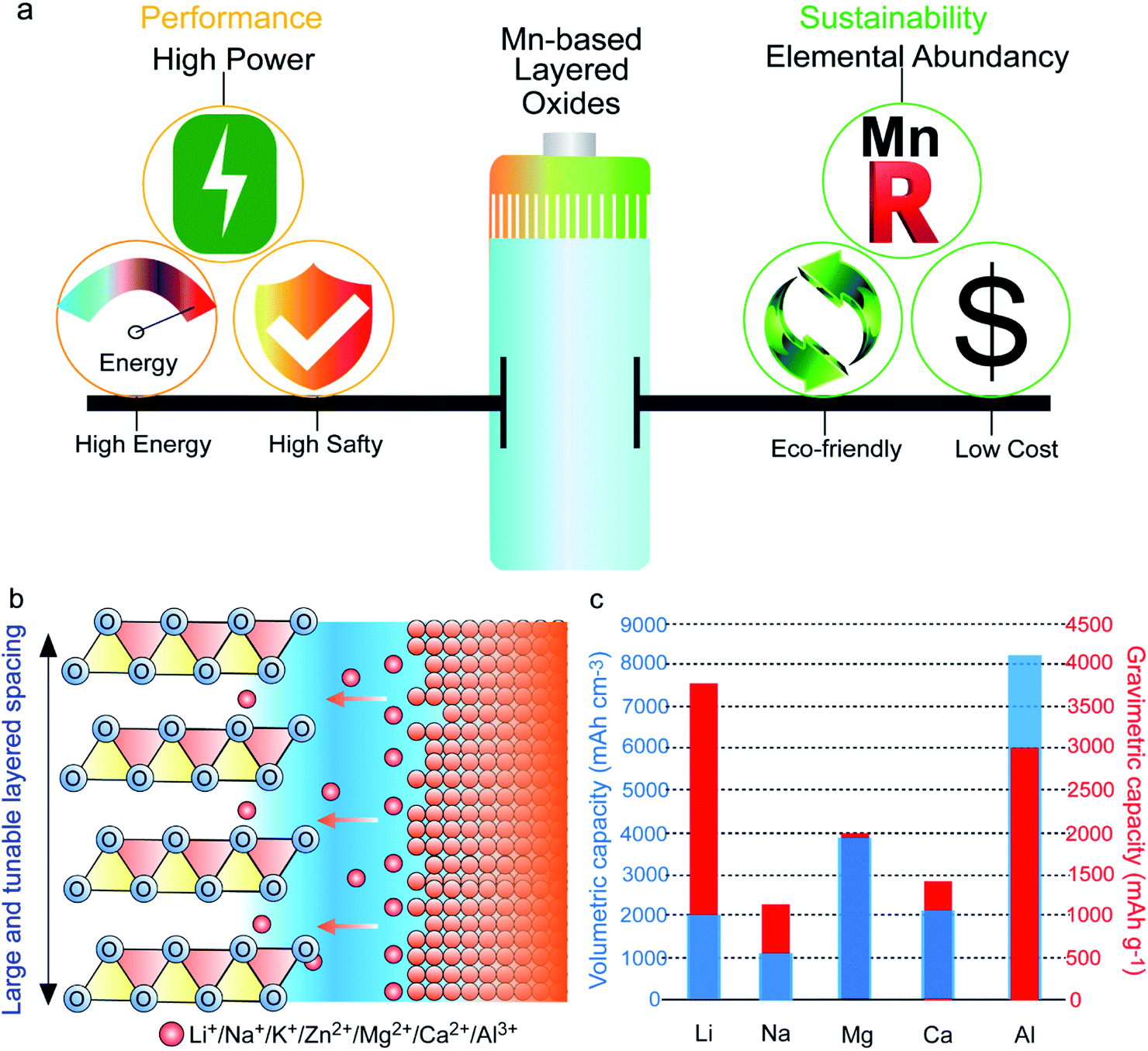 | ||
| Fig. 1 (a) Schematic illustrations of the balance between the electrochemical performance and sustainability in MLO materials. (b) MLO materials with large and tunable layered spacing enabling the insertion of various valence ions. (c) Volumetric capacity and gravimetric capacity for the various metal anodes. | ||
The typical MLO materials are built by alternately layering TM–oxygen and alkaline metal ions. The TM is coordinated in an octahedral geometry by oxygen, and the alkaline metal ions are inserted in prismatic (P), tetrahedral (T), and octahedral (O) configurations, corresponding to the P2/P3, T2, and O2/O3 phases, respectively (Fig. 2a), in which the numbers 2 and 3 represent the repeat period of the TM–O layers.21,22 In addition, a special kind of MLO material, called birnessite, comprises a mixed-valent oxide surrounded by six oxygen atoms to constitute a basic unit [MnO6] octahedron with cations of various valences (e.g., K+, Na+, Zn2+) and crystal water filling the interlayers.23,24 Birnessite, with 2D interlayer space for ionic diffusion, is a hydrous Mn oxide. Layered oxides were first applied in energy storage by J. B. Goodenough in 1980;25 substantial efforts have since advanced the development of high-performance MLO materials for various energy storage purposes (Fig. 2b).26–30 Although remarkable progress has been made, the applications of MLO materials are still limited by irreversible phase transition, Mn dissolution/disproportionation reactions, interfacial degradation arising from Mn2+, and crack formation (Fig. 3), which lead to rapid electrochemical degradation. It is worth noting that the root of these detrimental issues is local MnO6 octahedron distortion caused by the Jahn–Teller (J–T) effect. The J–T theorem was proposed by H.A. Jahn and E. Teller in 1937;32 due to this effect, a nonlinear molecular system suffers from instability in the degenerate electron state. Mn has several oxidation states (+2, +3, +4, +7), and electrochemical redox reactions usually happen between the +4 and +2 oxidation states. The ligand field of Mn4+ is shown at the center of Fig. 3. The Mn ions are coordinated by six oxide ligands and are symmetrically arranged along the Cartesian axes. The electric field of the octahedrally arranged ligands separates the d orbitals of Mn into doubly degenerate eg (dz2 and dx2−y2) and triply degenerate t2g (dxy, dxz, and dyz) sets. The eg orbital set of Mn4+ is empty, thus possessing a cubically symmetrical electron density. This feature confers stability to Mn4+-derived layered materials. However, when Mn3+ is coordinated with oxygen, like in LiMnO2, the 3d4 configuration of Mn3+ exhibits an asymmetrical electron density distribution and a high-spin state due to the single-electron occupancy in the eg level.33–35 In this case, the two axial Mn–O bonds are elongated and the four equatorial bonds are shortened to relax this unfavorable state, i.e., the J–T distortion, transforming MnO6 from the cubic configuration into the tetragonal configuration. As such, this structural evolution at the atomic level detrimentally impacts the physicochemical properties of MLO materials.
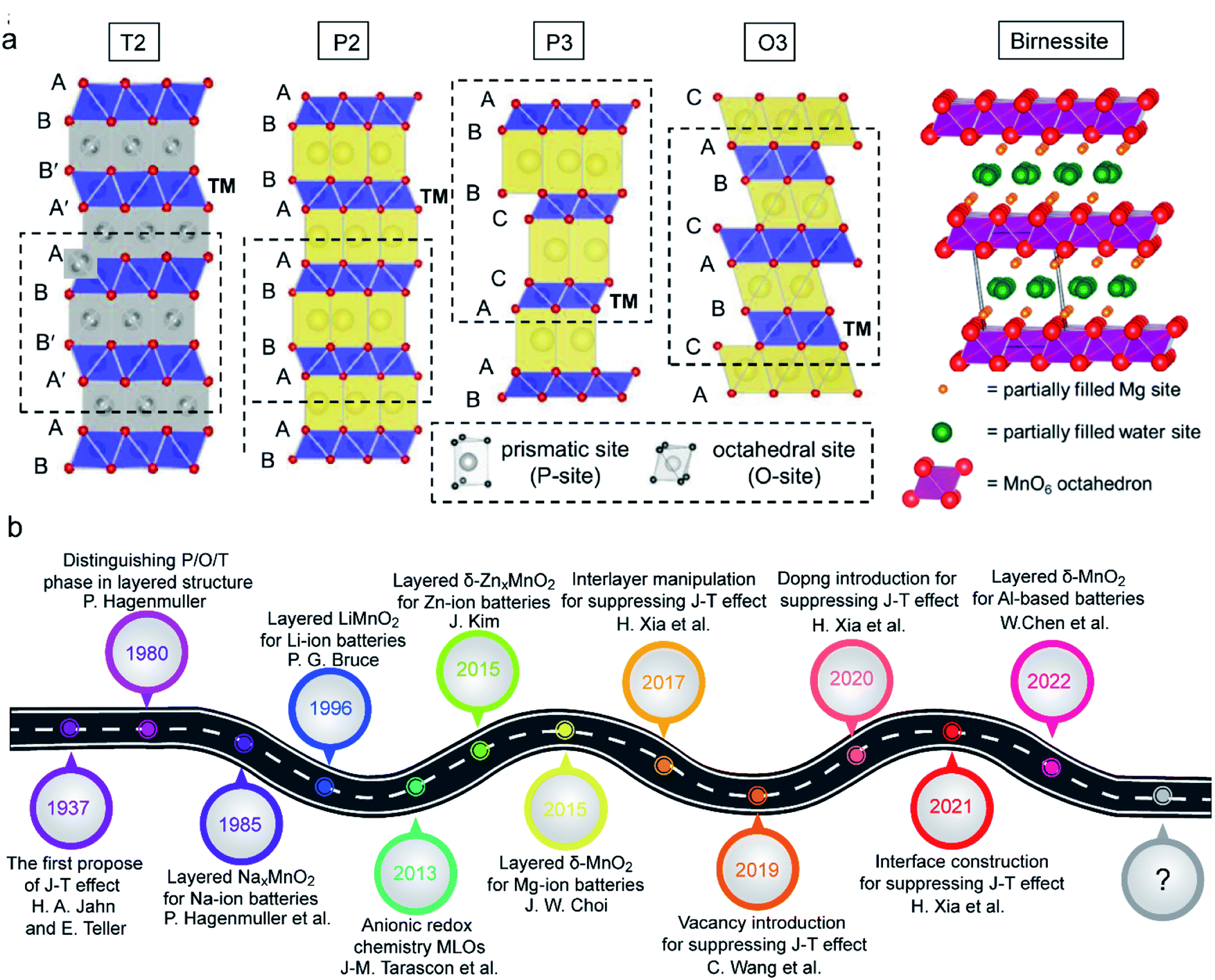 | ||
| Fig. 2 (a) Schematic illustrations of the crystal structures of the birnessite phase, reproduced with permission.31 Copyright 2015 American Chemical Society. Schematic illustrations of T, P, and O phases. Reproduced with permission.22 Copyright 2021 Wiley-VCH. (b) Main progress of MLOs in various energy storage systems, including Li, Na, K, Zn, Al, etc. batteries, as well as supercapacitors. | ||
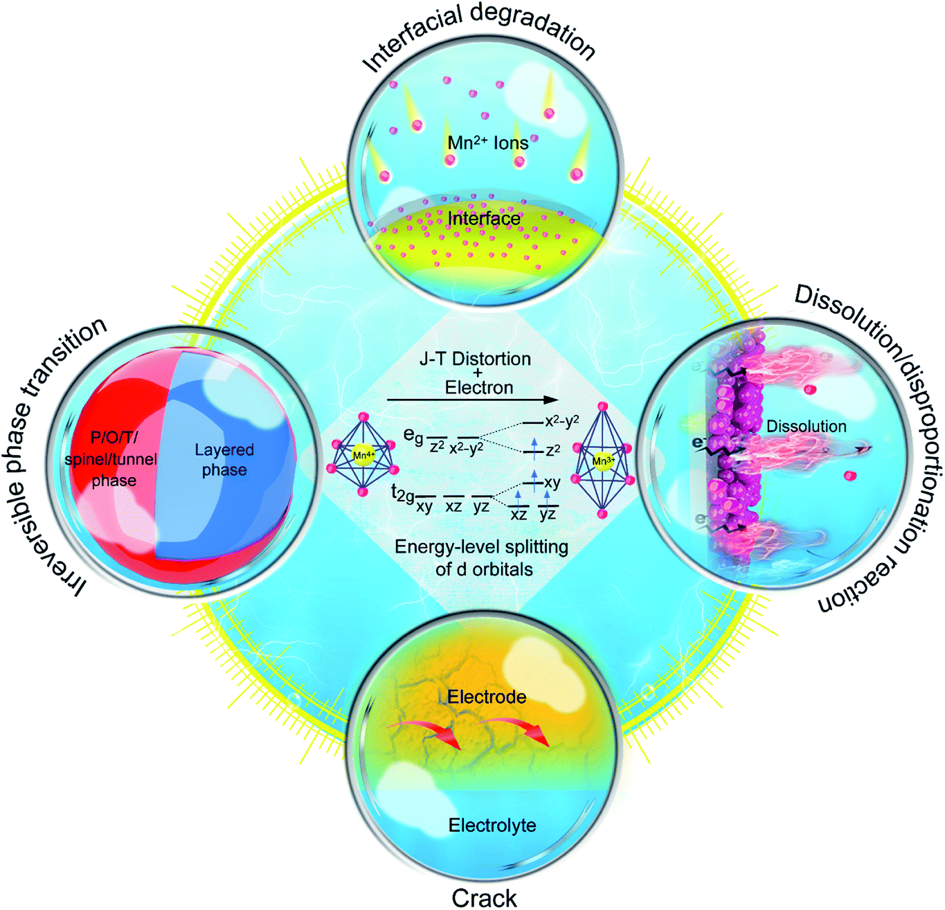 | ||
| Fig. 3 The main electrochemical degradation mechanisms induced by J–T distortion in MLO cathodes. | ||
In attempts to prevent J–T distortion, various strategies have been developed to optimize structural stability at the atomic level during the charging/discharging process.7,34,36–40 These strategies can be divided into four categories (Fig. 3): (i) elemental doping, (ii) interlayered structure manipulation, (iii) vacancy introduction, and (iv) novel structural design. Although previous reviews have discussed Mn-based and/or layered cathode materials, the relationships between the structural evolution of MLO materials at the atomic level and capacity fade during the ion deintercalation/intercalation processes have not been systematically reviewed.12,41–43 In particular, a comprehensive review of the atomic-level mechanisms and strategies that remedy the electrochemical degradation of MLO cathodes in various valence ion-based electrochemical energy storage devices is needed.
In this review, we discuss the relationships between the intrinsic structure, electrochemical behaviors, and degradation mechanisms from the perspective of the atomic level and summarize the effective strategies for structural degradation during ion deintercalation/intercalation. We begin by discussing the different electrochemical behaviors resulting from alkaline ion insertion into MLO cathodes, from monovalent ions to trivalent ions. Moreover, we describe the corresponding electrochemical degradation caused by irreversible phase transition, Mn dissolution/disproportionation reactions, interfacial degradation arising from Mn2+, and crack formation in various energy storage devices, as well as the relationships between these degradation mechanisms and J–T distortion. Finally, we outline the recent achievements in overcoming the aforementioned bottlenecks and provide perspectives on the future development of high-performance MLO materials.
2. Fundamental understanding of alkaline ion insertion in MLO materials
Energy storage devices based on multivalent metal ions with high crust abundances, such as Ca, Mg, Zn, and Al, have the potential to satisfy the future demands of large-scale energy storage. Therefore, as an alternative to the development of conventional monovalent metal energy storage (e.g., Li batteries, Na batteries), divalent and trivalent ion intercalation is of particular importance. Nevertheless, unlike monovalent ions, the intercalation of divalent/trivalent ions into electrode materials is difficult due to the strong electrostatic interactions between the electrode material atoms and the highly charged intercalation ions. Diffusion channels that allow ion mobility are crucial to enable multivalent ion insertion. Notably, the large and tunable interlayer spacing of MLOs can accommodate structural deformations, enabling the reversible insertion of both monovalent ions and multivalent ions into MLO materials. Layered MLO structures possess 2D diffusion channels, providing a favorable structure for ionic diffusion and guaranteeing fast kinetics. The MLO materials with different structures used in various energy storage systems are summarized in Table 1, in which MLO materials exhibit superior performance due to their large and tunable interlayered spacing. In the next sections, we discuss the insertion of monovalent, divalent, and trivalent ions in MLO cathodes.| Energy storage type | Material | Crystal structure | Interlayer space (Å) | Electrolyte type | Rate performance | Ref. |
|---|---|---|---|---|---|---|
| Supercapacitor | δ-MnO2 | Birnessite | 7.2 | Aqueous | 250 F g−1 at 0.2 A g−1 | 19 |
| 125 F g−1 at 10.0 A g−1 | ||||||
| Li-ion battery | LiMnO2 | O3 | 5.4 | Organic | 286 mA h g−1 at 1C | 44 |
| 183 mA h g−1 at 12C | ||||||
| Li-ion battery | Li2/3[Ni1/3Mn2/3]O2 | T2 | 5.0 | Organic | 180 mA h g−1 at 0.1C | 45 |
| Li-ion battery | Li2MnO3 | O2 | 4.7 | Organic | 400 mA h g−1 at 0.01 A g−1 | 46 |
| Na-ion battery | NaMnO2−y −δ(OH)2y | Birnessite | 7.2 | Organic | 211 mA h g−1 at 0.2C | 47 |
| 156 mA h g−1 at 50C | ||||||
| Na-ion battery | NaxMnO2 | O3 (x = 0.9–1.0) | 5.7 | Organic | 185 mA h g−1 at 0.1C | 48 |
| P2 (x = 0.6–0.8) | 194 mA h g−1 at C/30 | |||||
| K-ion battery | K0·77MnO2 | Birnessite | 7.2 | Organic | 77 mA h g−1 at 1 A g−1 | 24 |
| Zn-ion battery | Zn–MnO2 | Birnessite | 9.2 | Aqueous | 242 mA h g−1 at 3 A g−1 | 49 |
| Ca-ion battery | CaMnO2 | Birnessite | 6.9 | Aqueous | 89 mA h g−1 at 2 A g−1 | 50 |
| Mg-ion battery | MgMnO2 | Birnessite | 6.7 | Aqueous | 55 mA h g−1 at 8 A g−1 | 51 |
| Mg-ion battery | MnO2 | Birnessite | 9.7 | Aqueous | 110 mA h g−1 at 1C | 52 |
| 50 mA h g−1 at 10C | ||||||
| Al-ion battery | MnO2 | Birnessite | 7.0 | Aqueous | 59 mA h g−1 at 0.1 A g−1 | 53 |
2.1 Monovalent ion insertion in MLO materials
The weak interactions between the inserted monovalent ions and atoms in the MLO structure enable fast kinetics and high electrochemical performance; Li+, K+, and Na+ insertion in various MLO cathodes has been comprehensively examined. The interlayers of birnessite are filled by alkaline monovalent cations and crystal water.23,24 Such a material is configured as an edge-sharing [MnO6] octahedron, separated by a complex interlayer environment comprising a single layer of H2O and cations in two similar sites. The interlayer spacing is often approximately 7.0 Å but can increase to ∼10.0 Å with further hydration and decrease to ∼5.5 Å upon dehydration.54 Moreover, the valence state of Mn is not completely Mn4+, and the average valence is usually between 3.6 and 3.8, indicating the presence of some Mn3+ in the birnessite structure. Therefore, the physicochemical properties of birnessite can be altered by modulating the layer spacing, the interlayer water content, and the species of intercalated cations. Birnessite is often used for aqueous energy storage. In neutral pH electrolytes, birnessite δ-MnO2 shows linear galvanostatic charge–discharge curves and rectangular cyclic voltammograms (CVs). This electrochemical behavior has been described as non-faradaic electrical double layer formation due to the nonspecific adsorption of partially solvated or desolvated ions.59 Nevertheless, experimental results have demonstrated that the electrochemical behavior of δ-MnO2 matched with monovalent ions is associated with pseudocapacitance, Mn oxidation state changes, local bonding, and structure.18 In the charge/discharge process, the monovalent cations in the electrolytes, such as Na+ and K+, can be intercalated/deintercalated into the layered space of δ-MnO2.60 However, unlike the intercalation of other cations, the integration and confinement of structural water within the interlayers of δ-MnO2 leads to electrochemical behaviors between faradaic and traditional capacitive non-faradaic electrical double layer intercalation (Fig. 4a).19,61,62 These confined water molecules in the interlayers weaken the interactions between the intercalated ions and MnO2 layers, resulting in minimal structural change and potential dependence (manifested as rectangular CV curves). Boyd et al.19 performed electrochemical quartz crystal microbalance experiments (EQCM) and discovered that the alkali cation and H2O intercalation into δ-MnO2 simultaneously proceeded during the electrochemical process. In sharp contrast, the CV curves of δ-MnO2 materials with no water showed well-defined peaks originating from the structural transitions. When H2O molecules entered the interlayers, the CV curves became featureless, and the corresponding X-ray diffraction pattern showed only a small change in the interlayer spacing during intercalation/deintercalation.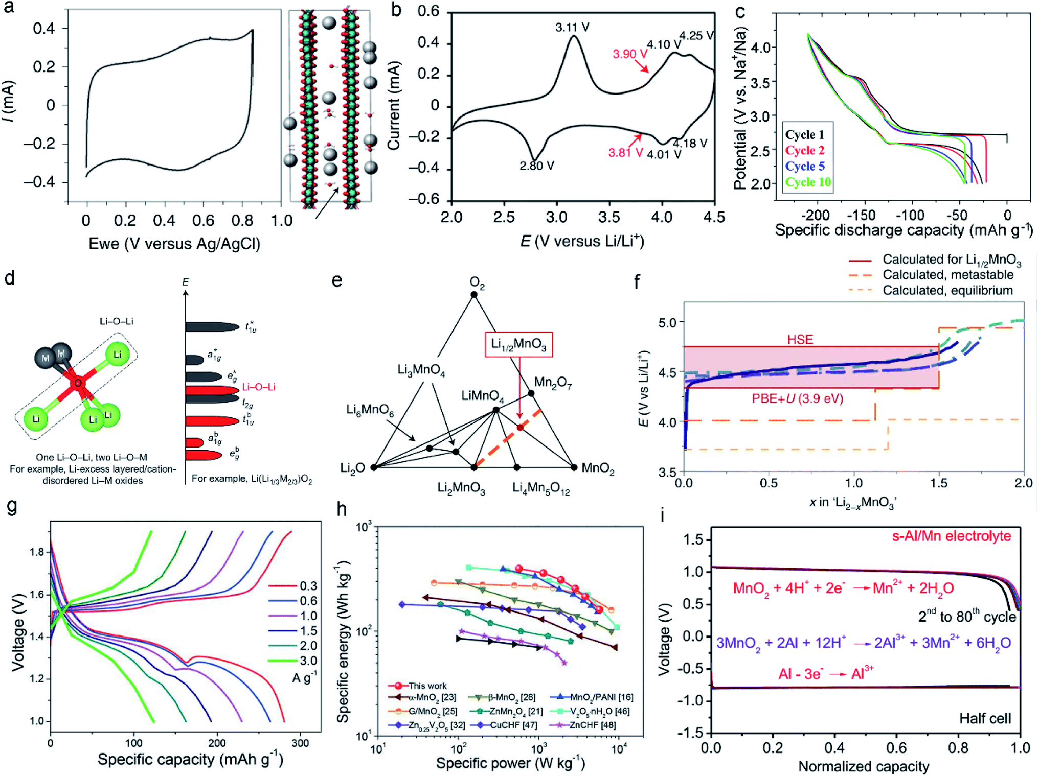 | ||
| Fig. 4 (a) The typical CV of δ-MnO2 showing nearly capacitive behavior at 10 mV s−1 and simulation of H2O and K+ intercalation into δ-MnO2. Reproduced with permission.19 Copyright 2021 Springer Nature. (b) CV curve of the spinel–layered LiMnO2 cathode at 0.1 mV s−1. Reproduced with permission.44 Copyright 2021 Springer Nature. (c) Discharge curves of NaMnO2 at a rate of 10 mA g−1. The 1st, 2nd, 5th, and 10th cycles are represented by the curves with black, red, blue, and green, respectively. Reproduced with permission.55 Copyright 2014 American Chemical Society. (d) Local atomic coordination around O with two Li–O–M and one Li–O–Li configurations in Li-excess layered oxides. Reproduced with permission.56 Copyright 2016 Springer Nature. (e) The metastable phase diagram suggests that the Mn would be oxidized to the +7 state in the form of Mn2O7 and LiMnO4 when the formation kinetics of oxygen–oxygen bonds is sluggish. (f) Comparison between the voltage curves for the Li2MnO3 component of composites and Li2MnO3. Reproduced with permission.57 Copyright 2019 Springer Nature. (g) Charge/discharge curves at different current densities in ZIBs. (h) Ragone plot of ZIB-based layered MnO2. Reproduced with permission.58 Copyright 2019 Royal Society of Chemistry. (i) Discharge curves at the current density of 2 mA cm−2 in the Al/MnO2 battery. Reproduced with permission.28 Copyright 2022 Elsevier. | ||
As for the P/O/T phases, such as layered LixMnO2 and NaxMnO2, both consist of edge-sharing MnO6 octahedra separated by an interlayer of Li+ or Na+. Generally, most AMO2 (A = Li, Na; M = transition metal) phases have α-NaFeO2-type structures.63,64 However, when M is Mn3+, the crystal structure is monoclinic (space group C2/m), not orthorhombic, due to the strong J–T effect of high-spin Mn3+, which distorts the local site symmetry near Mn3+ from a regular octahedron and changes the corresponding crystal structure.65–67 The practical use of layered LiMnO2 in batteries is greatly hindered by severe structural degradation and rapid capacity fading. The small difference in size between Mn3+ and Li+ makes it difficult to form the layered LiMnO2 structure; Mn migration into the Li layer is often observed.68,69 Thus, an irreversible transition from the layered structure to the spinel structure usually occurs during the first deintercalation. Specifically, the formation of Li vacancies during oxidation results in covalent MnO2 slab formation and an empty interlayer space with face-to-face O layers. Correspondingly, the Mn ions tend to migrate to the Li layers to homogenize the charge distribution.70 To realize this transfer process, the Mn ions must cross a tetrahedral interstitial site. Low-spin Co4+ (d5), low-spin Co3+ (d6), low-spin Ni4+ (d6), and low-spin Ni3+ (d6) have very strong stability in octahedral sites. However, high-spin Mn3+ ions are prone to disproportionate into Mn2+ and Mn4+.71,72 Mn2+ (d5) is much less stable in octahedral sites than in tetrahedral sites, promoting movement and thus fast capacity fade. As such, the crystal field stability determines whether the TM ions transfer.73 Generally, stable redox reactions of monoclinic layered LiMnO2 can be observed at ∼3.9 V in the cathodic scan and 3.8 V in the anodic scan (Fig. 4b).44,74,75 However, the sizes of Na+ and Mn ions differ, allowing NaMnO2 to form the O3-type layered structure. Meanwhile, there is a great increase in the covalency of the Mn–O bond due to the Na–O bond, which has a much stronger ionic character than the Li–O bond, improving the stability of the tetravalent ions.70,76,77 First-principles calculations suggest that monoclinic NaMnO2 is stable, whereas LiMnO2 prefers an orthorhombic structure.78,79 Nevertheless, with the decrease in Na content in NaxMnO2, the phase changes from O3-type (x = 0.9–1.0) to P2-type (x = 0.6–0.8) and P3-type (x = 0.5–0.6) oxygen packing.80 As the P3 and O3 structures share the same MnO6 octahedral orientation, the layer of O3-type NaMnO2 glides during the deintercalation of Na+ to form P3-type NaxMnO2. This process may be reversible; however, the stress/strain induced by phase transition significantly limits long-term cycling. In addition, NaxMnO2 materials exhibit different electrochemical behaviors; many voltage plateaus are observed during the deintercalation/intercalation process due to the ordering of Na+/vacancy (Fig. 4c).55,81
Li-rich MLO materials like O3-type Li2MnO3 have attracted extensive attention due to their large capacities, which significantly exceed those of conventional Li-containing cathode materials.82,83 As such, substantial efforts have focused on utilizing the Li+ in Li2MnO3 with 100% efficiency. The structure of Li2MnO3 is usually expressed as Li[Li1/3Mn2/3]O2, consisting of Li layers between MO2 (M = Li1/3Mn2/3) layers, in which one third of the Mn is replaced by Li in a specific honeycomb-like occupation pattern.84,85 This feature results in excess Li. It is worth noting that Li-rich Mn-based oxide (LRMO) cathode materials are usually synthesized by combining xLi2MnO3 and (1−x)LiTMO2 (TM = Ni, Co, Mn), when x = 0.5, in the form of Li1.2Mn0.54Co0.13Ni0.13O2.86,87 However, in addition to the J–T distortion in LiTMO2, the anionic redox reactions triggered by Li2MnO3 activation accelerate the migration of Mn ions. These behaviors imply unusual structural degradation,91–93 including large voltage hysteresis, a gradual decrease in the average voltage during cycling (voltage fade), and an “activation” plateau (4.5 V vs. Li/Li+) during the first charge.85,94 In the first step of the delithiation process, TM cations are oxidized. At a high voltage between 4.5 and 4.7 V, there is a voltage plateau, and most Li+ is deintercalated from the material. Meanwhile, in the bulk region, some oxygen anions are oxidized to O(2−x)−. The anionic redox is due to the existence of the Li–O–Li configuration, in which unhybridized O 2p states (Li–O–Li states) are generated.56,95,96 Because the energy of electrons in the Li–O–Li configuration is higher than in the other O 2p states (Fig. 4d), the oxygen in the Li–O–Li configuration is preferentially oxidized at a relatively low voltage of ∼4.3 V. It was recently proposed that the Mn can be oxidized from +4 to +7 through three-phase reactions, forming the Mn7+ compounds Mn2O7 and LiMnO4 and the Mn4+ compounds Li4Mn5O12 and MnO2.57 The phase diagrams in Fig. 4e facilitate the understanding of the electrochemical reaction mechanisms of Li-rich MLO materials. However, the detected voltage curves do not follow these three-phase reactions (Fig. 4f), which is mainly attributed to the slow kinetics of these reactions resulting from the long-range diffusion of Mn or O. Compared with Li, the relatively slow migration of Mn leads to the formation of a metastable Li2−xMnO3 compound. The oxygen-redox hypothesis also demonstrates the formation of this metastable phase where the oxygen anion valence states are −1.56,97
2.2 Divalent and trivalent ion insertion in MLO materials
Compared with monovalent cations, inserting divalent and trivalent cations in MLO materials can lead to higher energy density. The layered hydrated TM oxide birnessite has attracted tremendous attention because it contains crystal water, which can not only change the interlayered spacing but also weaken the polarizing nature and accelerate the diffusion of divalent and trivalent cations. As the interlayers of birnessite contain multivalent ions and crystal water, their spacing can be expanded to nearly 1 nm, allowing different layered structures to be obtained. Herein, the insertion of divalent and trivalent cations in MLO materials is demonstrated in the context of typical Zn-ion and Al-ion battery applications, respectively.Zn-ion batteries possess high gravimetric and volumetric capacity (820 mA h g−1 and 5854 mA h cm−3). In addition, the excellent reversibility of Zn plating/stripping reactions, safety, and low toxicity make Zn-ion batteries a promising energy storage device. The insertion of Zn2+ into birnessite forms the layered δ-ZnxMnO2. Alfaruqi et al.27 demonstrated the high capacity of birnessite-based Zn-ion batteries (>250 mA h g−1). Despite the high capacity of layered δ-ZnxMnO2 compared with tunnel MnO2, δ-ZnxMnO2 still has low capacity retention during electrochemical processes. Recent research demonstrated that the capacity decay is due to the phase transition from the layered structure to the spinel structure and the dissolution of Mn ions in electrolytes.98 Wang et al.58 prepared a mesoporous layered MnO2 nanosphere with H2O and Zn2+ in the interlayers (Fig. 4g and h), which had a high specific capacity (358 mA h g−1 at 0.3 A g−1). In addition, in situ and ex situ characterizations have been used to uncover the structural changes of ZnxMnO2 during charge/discharge cycling. Energy storage mechanism that involves the co-insertion/extraction of H+ and Zn2+ along with the deposition/dissolution of zinc sulfate hydroxide hydrate on the electrode surface was discovered. In general, the specific structural degradation between Zn-batteries in aqueous solution and Li/Na-batteries in the organic solution is different due to their different electrolytes and inserted ions. Compared with the inserted Li+ or Na+ with monovalence, divalent Zn2+ has much higher electrostatic repulsion and atomic radius, which inevitably causes larger volume change of MLO materials during the electrochemical processes and thus results in more severe layered structure distortion than the insertion of Li+/Na+ into MLO materials.99,100 The electrolytes used in Zn batteries are always acidic, in which higher H+ concentration exists. As a result, MLO materials suffer from the more serious dissolution issues of Mn2+ originating from the disproportionation reaction than the organic electrolyte that has low H+ concentration used in Li/Na-batteries. In addition, Alfaruqi et al. proposed that layered MnO2 in the process of Zn-ion insertion undergoes a series of structural transformations: layered MnO2–layered ZnxMnO2–Zn-inserted phase–spinel ZnMn2O4.98 Although the phase transition during the discharging can be reverted to the layered MnO2 during the initial charging, these phase transformations may induce the huge change of layered structure and thus easily results in the structural degradation during the long-term cycles, which is demonstrated by the complete phase transformation from the layered structure into the spinel structure after prolonged cycles. Additionally, the co-intercalation mechanism of H+ and Zn2+ has been demonstrated.101 Unfortunately, the effect of co-intercalation of H+ and Zn2+ on structural degradation is not clear until now. But it must cause different degradation mechanisms compared with the single Li+/Na+ insertion in Li/Na-batteries.
Al-based batteries, which have three-electron redox states (from Al3+ to Al) and are low cost and easy to handle, provide an alternative to commercial Li/Na-ion batteries. Birnessite, with large interlayer spacing, enables the reversible intercalation and extraction of Al3+, which can deliver high capacity. However, the discharge rate is relatively low in this layered structure due to the sluggish diffusion kinetics of Al3+ in the interlayers. The strong electrostatic interaction between Al3+ and oxygen in layered birnessite can result in the formation of inactive AlxMnO2 and, subsequently, fast capacity decay. Therefore, it is crucial to prevent the direct insertion of Al3+ ions into the lattice. To address these issues, electrolyte engineering has been proposed to tune the solvation structure of Al3+. For example, Xu et al.28 developed an Al-based battery with high stability by tuning the electrolyte. When 1 M MnCl2 and 4.4 M AlCl3 were used, the intercalation of Al3+ was prohibited because of the large solvation structure of AlCl1.8(H2O)4.21.2+ that formed in this electrolyte.28 Correspondingly, the Al–MnO2 batteries delivered a large specific capacity of 493 mA h g−1 and stable cycling behaviors over 1000 cycles, demonstrating the potential of trivalent ion-based energy storage (Fig. 4i).
3. Degradation mechanisms
J–T distortion, which elongates the two axial Mn–O bonds, induces MnO6 to transform from the cubic form into the tetragonal form. This atomic structure evolution influences the physicochemical properties of MLO materials and impacts their electrochemical performance. Generally, the degradation issues caused by J–T distortion in MLO cathodes can be divided into (i) irreversible phase transition, (ii) dissolution/disproportionation reaction, (iii) interfacial degradation arising from Mn2+, and (iv) crack formation. As a result, a comprehensive understanding of these problems is necessary for developing MLO-based energy storage devices with high structural stability and prolonged life spans.3.1 Irreversible phase transformation
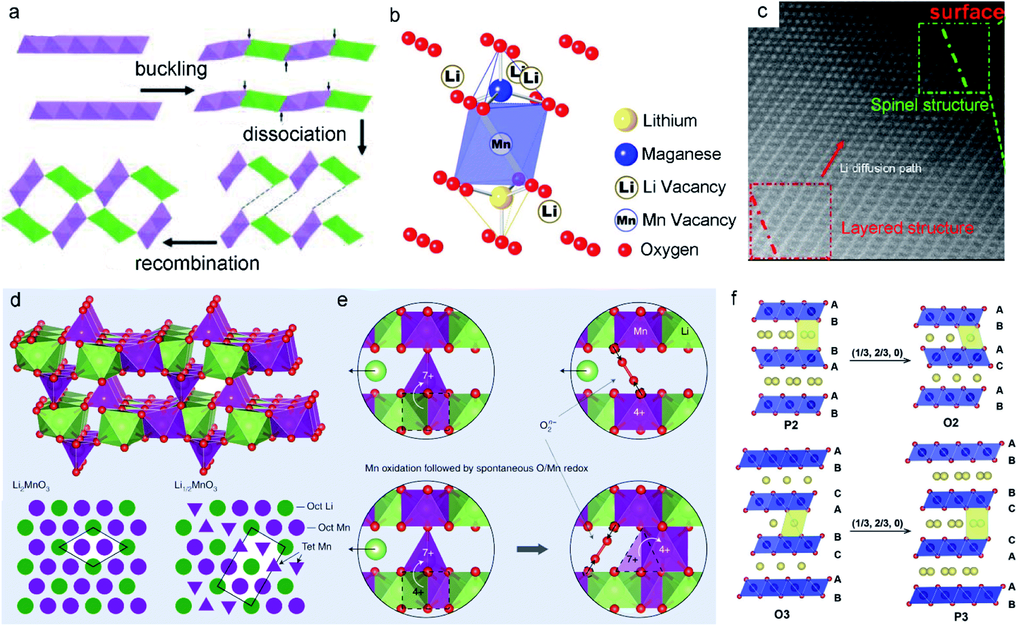 | ||
| Fig. 5 (a) Schematic illustration of the phase transformation process of the layer into tunnel through layer buckling. Reproduced with permission.88 Copyright 2011 American Chemical Society. (b) Schematic illustration of the Li/Mn dumbbell configuration. Reproduced with permission.48 Copyright 2011. The Electrochemical Society. (c) Phase transition from the layered structure to the spinel of cycled layered LNMO after 100 cycles. Reproduced with permission.89 Copyright 2013 American Chemical Society. (d) Proposed Li1/2MnO3 structure showing the Li2MnO3 cathode material component at the end of the activation plateau. (e) The charge mechanisms in Li-rich MLO oxides. Reproduced with permission.57 Copyright 2019 Springer Nature. (f) Schematic illustration of the layered Na-containing oxides for P2-type, O2-type, O3-type, and P3-type stackings. Reproduced with permission.90 Copyright 2017 Wiley-VCH. | ||
Gu et al.89 reported that newly formed spinel domains show random orientation within the same particle during cycling. The extraction of Li+ ions together with the loss of oxygen from Li2MnO3 induces the displacement of TM cations. This change further destroys the lattice and creates numerous nanometer-scale spinel particles, leading to rapid capacity and voltage decay. Correspondingly, Li+ ions cannot intercalate in the transformed structure again, resulting in low initial coulombic efficiency. For example, in the first oxidation process, atomic columns in the Li layers can be observed in both the surface and bulk regions. This feature implies the migration of TM ions to the Li layer (Fig. 5c). Meanwhile, the development of pores and cracks among the layered nanoparticles results in lattice degradation and vacancy formation upon the extraction of Li+ ions, suggesting that the layered-to-spinel phase transition is a nucleation and growth mechanism. Recently, Radin et al.57 modeled the irreversible phase transition. As shown in Fig. 5d, a typical local configuration forms upon Li2MnO3 charging. Mn4+ remains in the [MnO6] octahedral sites, while Mn7+ tends to migrate to the tetrahedral sites in Li1/2MnO3. To form Li1/2MnO3, half of the Mn ions must migrate, with one quarter moving downward and one quarter moving upward (Fig. 5e). This behavior finally produces an unstable lattice structure.
As the large Na+ ions stabilize the prismatic sites in the P2 phase, MnO2 slabs tend to form octahedral sites, enabling the phase change from P2 to O2.90 For the O3-type phase, when a sufficient amount of Na+ is removed from the interlayers, MnO2 sheet gliding induces the formation of broad prismatic sites. The stacking of oxygen transits to AB, BC, CA, known as the P3 phase. In other words, the extraction of Na+ from both P2 and O3 phases generally causes the gliding of MnO2 sheets, promoting the phase transition (layer-to-layer). NaxMnO2 has a more complicated phase than its Li analogs due to the large size of Na+ coupled with the ordering arrangement of Na+ and vacancies. Because the MnO2 sheet gliding combined with the change in oxygen stacking brings severe structural degradation, cracks are often observed in NaxMnO2 during cycling. Therefore, reducing or suppressing these phase transformations is critical for improving the electrochemical performance.
3.2 Dissolution/disproportionation reaction
The J–T effect modulates the Mn–O bond lengths, and the strength of this distortion is related to the covalency of the Mn–O bonds. In contrast to the shorter axial Mn–O bonds, longer axial Mn–O bonds with weaker overlap have a higher negative charge (Fig. 6a).103 From a Lewis acid–base perspective, the axial oxygen atoms enhance the Lewis base strength and thus have high reactivity with acid. Generally, the electrolytes contain substantial H+, and these ions exclusively attack the axial oxygens that possess higher negative charges, resulting in severe Mn dissolution. For example, in Li-ion batteries, the LiPF6 salt in the electrolyte is prone to hydrolysis, and this process induces the formation of a strong Lewis acid, HF. The H+ in HF interacts with the elongated axial oxygens, generating H2O through oxide protonation. Meanwhile, an electron must transfer from the Mn to the axial oxide orbital; this charge transfer derives from the (dz2)1 orbital of Mn3+. Correspondingly, the protonation process along with a metal-to-ligand electron transfer increases the oxidation state of the Mn ions. Unfortunately, the formed Mn4+ ions are a strong oxidizer that can be directly converted to the J–T-stabilized free state (Mn2+) via a disproportionation reaction (the two-electron reduction pathway), and Mn2+ ions are easily dissolved into the electrolyte (Fig. 6b).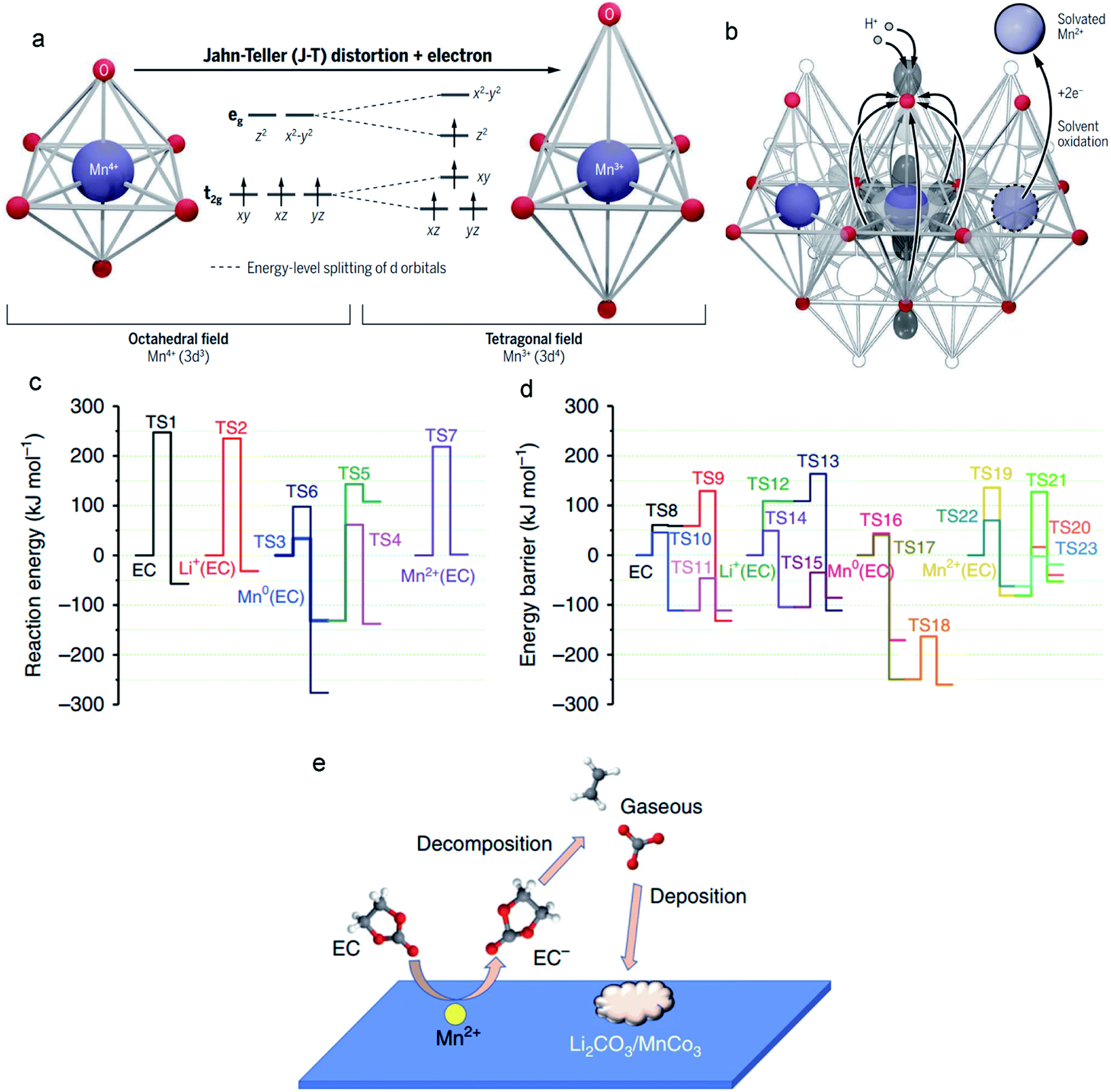 | ||
| Fig. 6 (a) The six equivalent Mn–O bonds (left) in MLOs are distorted and transformed into the four shorter equatorial bonds and two longer axial bonds (right). (b) H+ in the electrolyte attacks the axial oxide and transfers electrons from the manganese to oxygen. Reproduced with permission.103 Copyright 2020 American Association for the Advancement of Science. (c and d) Decomposition reaction of EC in electrolytes with/without interacting with metallic Mn, Mn2+, and Li+ before and after one-electron reduction. (e) The catalytic effect of Mn2+ on the decomposition of electrolytes. Reproduced with permission.104 Copyright 2019 Springer Nature. | ||
3.3 Interfacial degradation arising from Mn2+
Electrochemical degradation mechanisms originate from not only altering the surface structure of the MLO materials by the dissolution/disproportionation reaction, but also deteriorating the anode interface by the impact of Mn2+. The electric field force and/or concentration gradient drives the Mn ions in the electrolyte to the anode side where Mn ions tend to change the interface compositions by decomposing the electrolytes and/or depositing on the anode,111 resulting in interfacial degradation and electrochemical degradation.Specifically, the lower operation potential of conventional anodes like Li metal and graphite compared with the redox potential of Mn/Mn2+ results in the electroplating of soluble Mn2+ in the electrolyte on the anode. Simulations have indicated that the deposited Mn on the anode has high electrical conductivity or electrocatalytic properties, accelerating the decomposition of the electrolyte.112–114 The reconstructed SEI gradually covers the anode and affects the ionic diffusion kinetics. Recently, Wang et al.104 demonstrated that overlooking the effect of the solvation sheath on the Mn2+ ions is the main reason for the inaccurate conclusions that Mn is the final product of the anode. They proposed that the solvation sheaths around Mn2+ act as molecular-sized reaction vessels, in which the central Mn2+ activates its solvation member and guides the reaction process. This process explains why Mn atoms are rarely detected on anodes.115,116 If the solvation sheath begins to lose solvating members, Mn2+ ions can convert to Mn atoms, explaining the existence of Mn atoms on the surface of the anode. It was found that the Mn atoms (Fig. 6c) substantially decrease the activation energy of EC decomposition (from TS1 247.20 to TS3 33.69 kJ mol−1). In particular, when coordinated with Mn2+, the EC decomposition activation energy (TS7) is less than that of neat EC (TS1), which is only 16.57 kJ mol−1. After the EC anion receives an electron, the decomposition of EC (TS10) becomes much easier (Fig. 6d). With Mn2+, the reduced EC decomposition activation energy (TS21: 9 kJ mol−1) is higher than that of reduced EC (TS10), suggesting that the EC anion moves away from Mn2+ after receiving one electron. Nevertheless, the generated coordination vacancies around Mn2+ become occupied by other incoming EC molecules. Overall, the Mn2+ solvation sheath serves as a catalytic center on the electrode surface or in the electrolytes, which continuously accelerates the reduction of carbonate molecules, resulting in severe interfacial degradation, and cell performance fading (Fig. 6e).
3.4 Crack formation
It has been proven that the ion intercalation/deintercalation process causes the expansion and contraction of the structure, generally resulting in a high strain on the materials that gradually induces cracking and disintegration.117,118 Moreover, irreversible phase transition and Mn dissolution have been demonstrated to cause crack formation and severe capacity degradation.119 Therefore, the observed macroscale cracks originate from the evolution of the atomic-scale structure.120 By deeply analysing the atomic structure change, we can elucidate the crack formation process. Recently, Sharififi-Asl et al.110 used aberration-corrected scanning transmission electron microscopy to demonstrate the correlation between the atomic structure evolution during the electrochemical cycling of LRMO materials and the formation of cracks. They observed a spinel-type grain boundary derived from the migration of TM ions to the Li-octahedral sites (Fig. 7a). Strain analysis revealed that the spinel-type grain boundary had a high strain, which may serve as crack initiation points in the cycled LRMO (Fig. 7b). Furthermore, a nanocrack was observed initiating on the grain boundary, which could develop into a large-scale crack in the cathode during further cycling. Apart from the irreversible phase transition from the layered structure to the spinel or rock-salt phase, a disordered phase was also observed (Fig. 7c). The energy-dispersive spectroscopy map shows Ni enrichment and Mn depletion in the disordered area (Fig. 7d). The depletion of Mn is attributed to the dissolution of Mn at the high-energy grain boundaries, which further accelerates the diffusion of Ni toward these Mn vacancies.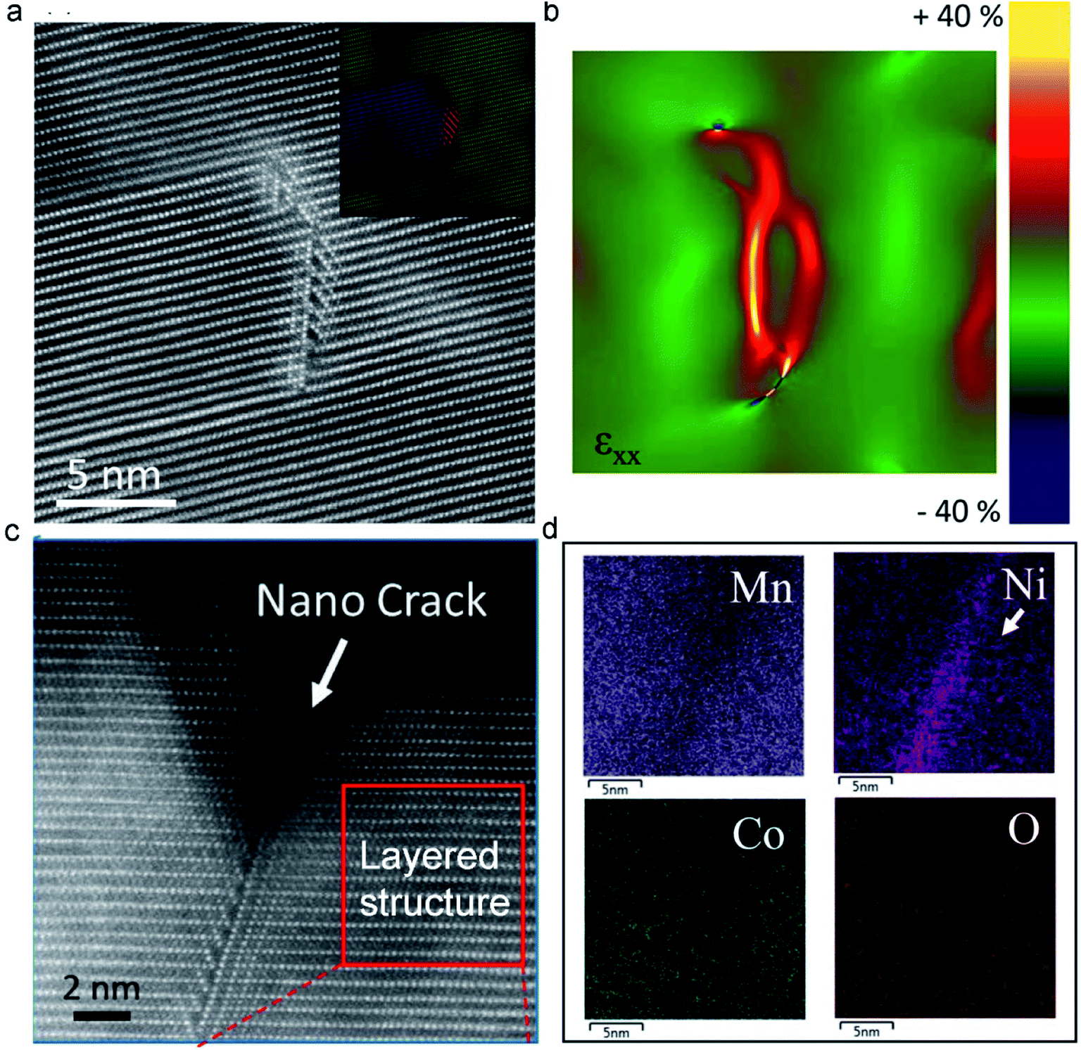 | ||
| Fig. 7 (a) The HAADF image of the pristine cathode material, forming a spinel-type grain boundary. (b) The generation of a large strain in the spinel-type grain boundary analyzed by Geometrical Phase Analysis (GPA). (c) Atomic resolution image of a nanocrack at the particle surface induced by a spinel-type grain boundary. (d) EDS maps collected from the nanocrack. Reproduced with permission.110 Copyright 2019 American Chemical Society. | ||
4. Remedies for electrochemical degradation in MLO cathodes
Numerous endeavors have been devoted to developing strategies at the atomic level to improve MLO-based energy storage performance. These strategies can be classified into the following categories: (i) elemental doping; (ii) interlayered structure manipulation; (iii) vacancy introduction; (iv) novel structural design. In this section, various strategies, synthesis methods, improved mechanisms, and electrochemical properties of typical MLO materials have been discussed and summarized, as shown in Table 2.| Material | Strategy | Synthesis method | Improved mechanism | Capacity | Capacity retention | Ref. |
|---|---|---|---|---|---|---|
| δ-MnO2 | Cr doping | Hydrothermal | Suppressing the elongation of the Mn–O bond | 250 F g−1 at 0.2 A g−1 | 69.1% (10![[thin space (1/6-em)]](https://www.rsc.org/images/entities/char_2009.gif) 000 cycles) vs.82.6% (30000 cycles) at 10 A g−1 000 cycles) vs.82.6% (30000 cycles) at 10 A g−1 |
124 |
| Na0.65Mn0.75Ni0.25O2 | F doping | Solid-state reaction | Inhibiting P3–O1 phase transition | 160 mA h g−1 at 0.1C | 75.1% vs. 83.1% (100 cycles) at 0.2C | 125 |
| Na0.833[Li0.25Mn0.75]O2 | Zn doping | Sol–gel method | Inhibiting P2–P2′ phase transition | 241 mA h g−1 at 0.2C | 41.3% vs. 96.9% (200 cycles) at 0.2C | 34 |
| Na0.65Mn0.75Ni0.25O2 | F/B co-doping | Solid-state reaction | Suppressing P3–O1 phase transition | 164 mA h g−1 at 0.1C | 86% vs. 75% (100 cycles) at 0.2C | 125 |
| Na0.5MnO2 | Na+ preintercalation | Hydrothermal | Stabilizing the interlayered structure | 366 F g−1 at 1A g−1 | 96% (10000 cycles) at 4 A g−1 |
126 |
| δ-MnO2 | Polyaniline intercalation | Chemical oxidation and reduction | Strengthening the layered structure and eliminating layered−spinel phase transition | 280 mA h g−1 at 0.2 A g−1 | 89.2% (5000 cycles) at 2 A g−1 | 101 |
| Na0.67Mn0.5Co0.5−xFexO2. | Fe3+ preintercalation | Solid-state reaction | Restraining the potential slab sliding | 160 mA h g−1 at 0.2C | 68.2% vs. 89.6% (100 cycles) at 10C | 127 |
| Na2/3[Zn1/9Mn7/9□1/9]O2 | Mn vacancy | Pechini method | Shortening the Mn–O bond length | 204 mA h g−1 at 0.02 A g−1 | 43.4% vs. 25.6% (100 cycles) at 0.02 A g−1 | 128 |
| Li1.22xNaxMn0.56Ni0.16Co0.08O2 | O vacancy | Solid-state reaction | Modulating the local Mn coordination environments | 250 mA h g−1 at 0.1C | 84% vs. 94% (100 cycles) at 0.5C | 40 |
| Li1.2[Mn0.66Co0.17Ni0.17]0.8O2 | Mixed vacancies of O and TM | Solid-state reaction | Prohibiting the O3–P3 phase transition | 220 mA h g−1 at 0.02 A g−1 | 86% (250 cycles) at 0.125 A g−1 | 129 |
| NaMnO2−y −δ(OH)2y | Novel monoclinic phase | Hydrothermal sodiation | Decreasing the volume change via a stable interlayer | 215 mA h g−1 at 0.2C | 94.6% (1000 cycles) at 10C | 47 |
| Spinel–layered LiMnO2 | Heterostructure construction | Electrochemical conversion | Modulating interfacial orbital ordering | 286 mA h g−1 at 1C | 90.4% (2000 cycles) at 12C | 44 |
| Li2Mn2/3Nb1/3O2F | Disordered structure | Ball-milling | Replacing the anionic reaction with a Mn reaction | 320 mA h g−1 at 0.01 A g−1 | 90% (25 cycles) at 0.02 A g−1 | 130 |
| Li1.2Ni0.2Mn0.6O2 | Surface structure design | Chemical vapor deposition | Charge compensation | 238 mA h g−1 at 0.5C | 99% (100 cycles) at 1C | 131 |
4.1 Elemental doping
Incorporating different foreign ions into MLO materials is a common practice for optimizing their intrinsic properties. Elemental doping, including anion and cation doping, has been demonstrated to significantly boost the structural stability of MLO materials, which not only changes the electronic structure but also suppresses irreversible phase transformations during ion intercalation/deintercalation. Various dopants have been proposed, including cationic dopants (Cr, Ta, and Al) and anionic dopants (F and Br).24,34,121–123Inferior structural stability and electronic conductivity have been demonstrated to limit the electrochemical performance of δ-MnO2. Zhao et al.124 proposed that incorporating Cr3+ into δ-MnO2 could boost its rate capability and cycling stability within the potential window of 0–1.2 V (vs. Ag/AgCl). δ-MnO2 without Cr doping undergoes severe J–T distortion, which increases the average Mn–O bond length and accelerates the migration and dissolution of Mn. Numerous dissolved Mn ions in the electrolyte generate cracks and pulverize the MnO2 nanosheet fragments to a moderate extent (Fig. 8a). In addition, the dissolved Mn ions form a precipitate in the electrolyte, impacting the electrochemical performance of the whole cell. Meanwhile, buckled Mn–O slabs are formed along with the J–T distortion, and these slabs dissociate and rearrange, leading to the irreversible phase transition from a layered structure to a 2 × 2 tunnel structure.88 Correspondingly, only 69.1% of the capacity of the pristine δ-MnO2 electrode is retained over 10000 cycles at the current density of 10 A g−1. The elongation of the Mn–O bond induced by the J–T distortion is effectively suppressed in Cr3+-doped δ-MnO2 (Fig. 8b), implying that the Mn ion migration barrier greatly increases. The reinforced birnessite shows significantly improved structural stability (82.6% capacity retention over 30000 cycles) in comparison with the pristine δ-MnO2, demonstrating the excellent effect of Cr doping in δ-MnO2 on suppressing the J-T effect and stabilizing the layered structure. Moreover, owing to the improved effect of Cr on the electronic conductivity of δ-MnO2, the Cr-doped δ-MnO2 showed a much higher capacity of 250 F g−1 than pristine δ-MnO2 with 178 F g−1 at the current density of 0.2 A g−1 with a high mass loading of ∼5 mg cm−2.
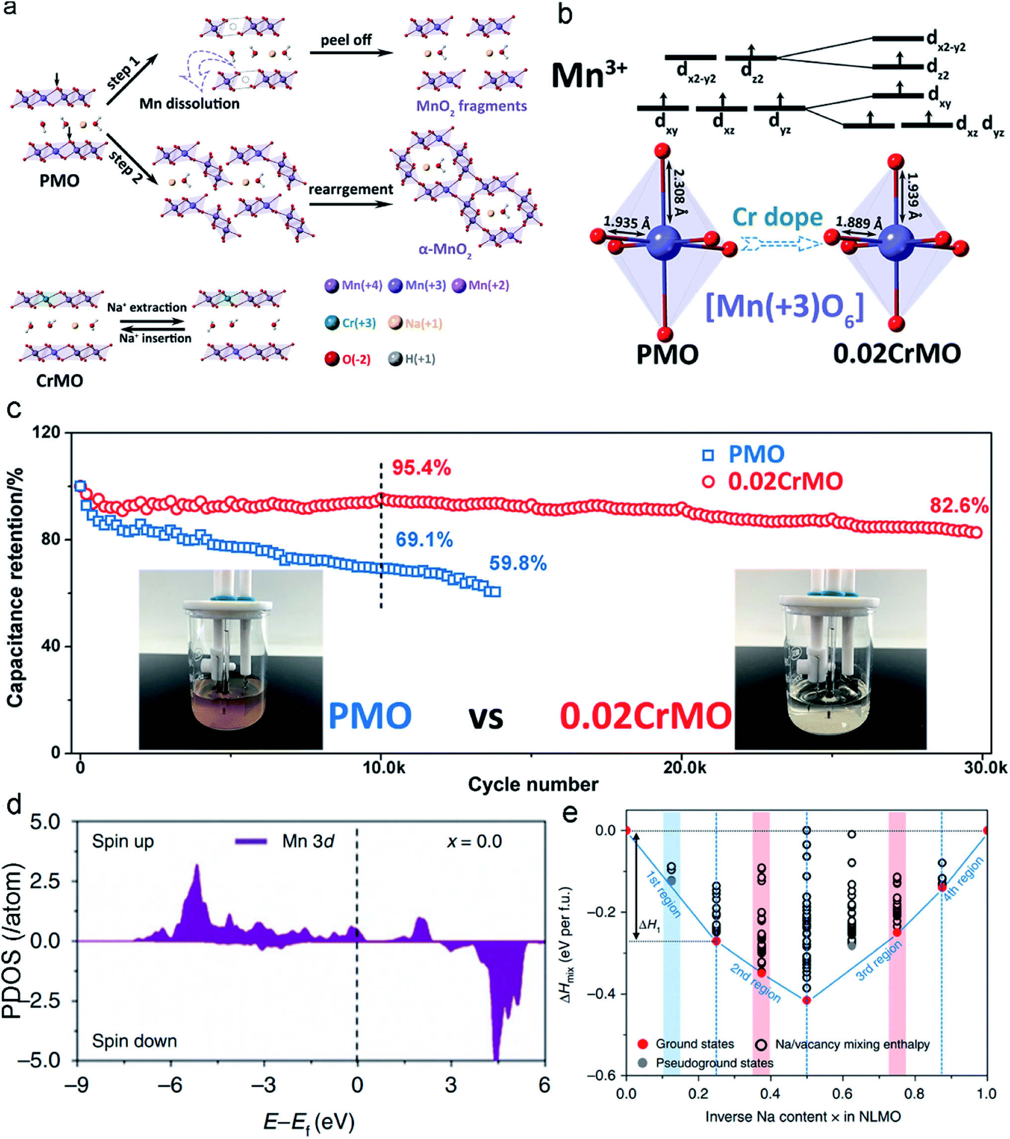 | ||
| Fig. 8 (a) Mechanisms of Cr-doping for the stabilities of the δ-MnO2. (b) The shortened Mn–O bonds after Cr-doping. (c) Cycling performances of the pristine δ-MnO2 and Cr-doping δ-MnO2 electrodes at a current density of 10 A g−1. Reproduced with permission.124 Copyright 2020 Royal Society of Chemistry. (d) The PDOS of the Mn3+ sites in the layered Zn-doping Na[Li0.25Mn0.75]O2. (e) The two atomic models include 8 Na atoms in each unit cell. Reproduced with permission.34 Copyright 2019 Springer Nature. | ||
To further validate the role of elemental doping, Zhang et al.34 modeled the Zn-doped layered Na[Li0.25Mn0.75]O2 material to explore its effect on thermodynamics and the electronic structure. Zn doping enables the oxidation of the Mn3+ center and thus increases the Mn4+ content of the centers in the Zn-doped materials (Fig. 8d). As a result, the materials are more structurally stable and undergo less J–T distortion, leading to negligible capacity decay of the Zn-doped layered Na[Li0.25Mn0.75]O2 electrode (99% capacity retention over 200 cycles), which is much higher than that of the pristine Na[Li0.25Mn0.75]O2 electrode (41% capacity retention over 200 cycles). From the perspective of thermodynamics, the formation energies of mixing enthalpy (ΔHmix) have an important influence on phase stability. The calculated thermodynamic energy values can confirm the structural stability of materials according to charge carrier content. Fig. 8e shows that Na[Li0.25Mn0.75]O2 comprises five ground states, whereas Zn-doped Na[Li0.25Mn0.75]O2 has seven ground states. Specifically, in the first region (x = 0–0.25), Zn doping can decrease ΔHmix, indicating a reduced volumetric strain (Zn-doped structure: εV = −0.027; undoped structure: εV = −0.04). In the second region (x = 0.25–0.50), Zn-doped Na[Li0.25Mn0.75]O2 is illustrated by the red circles located on the tie line, which directly confirm that desodiation occurs in the same phase. In undoped Na[Li0.25Mn0.75]O2, a pseudo-ground state appears, suggesting the formation of a new phase during the desodiation process. In the third region (x = 0.50–0.88), Zn-doped Na[Li0.25Mn0.75]O2 has one pseudo-ground state as marked by the grey circle (x = 0.63), indicating that phase dissociation may occur within the narrow region from x = 0.5 to x = 0.75. The extra ground states in Zn-doped Na[Li0.25Mn0.75]O2 are beneficial for suppressing the inherent phase transition that occurs in Na[Li0.25Mn0.75]O2.132 In contrast to its doped counterpart, two pseudo-ground states of undoped Na[Li0.25Mn0.75]O2 are shown as grey circles above the tie line (at x = 0.63 and x = 0.75, respectively), reflecting the phase separation to this extent during desodiation.
In summary, elemental doping can restrain the elongated bonds and stabilize the metastable structure to inhibit J–T distortion by changing the atomic structures around Mn ions, giving rise to a more stable structure. Additionally, the average valence of Mn ions may be tuned to above +3.5, which is beneficial to suppress the J–T effect, such as the introduction of the low-valence ions. Although elemental doping has achieved tremendous progress, some concerns should be noted. Presently, annealing at high temperatures is the most popular method to realize doping, but this process involves high energy cost and has low efficiency. In addition, it is difficult to precisely control the doping content and doping sites. Hence, it is highly desirable to explore the powerful and facile method of accurate doping with low energy costs.
4.2 Interlayered structure manipulation
Most MLO materials undergo the degradation of diffusion channels after long-term cycling processes. Therefore, the stabilization/enlargement of diffusion channels has emerged as a promising strategy based on improving the stabilization of the interlayer to accommodate J–T distortion. One of the characteristics of preintercalation in the interlayer hosts of MLO materials is the expansion of the interlayer spacing. The appropriate intercalated ions in the interlayer can serve as pillars to effectively expand and support this diffusion channel.24,133 Xia and co-authors126 proposed a hydrothermal synthesis to preintercalate Na+ into birnessite and prepared a high Na content birnessite (Na0.5MnO2) (Fig. 9a). It is known that preintercalating the Na+ protects the layered structure from collapsing. Meanwhile, the enhanced Na content in birnessite also extends the potential window from 0–1.0 V to 0–1.3 vs. Ag/AgCl (Fig. 9b). In addition, owing to the high diffusion kinetics of Na+ in large interlayers, the Na0.5MnO2 electrode could achieve a high rate performance and specific capacitance (366 F g−1 at 1 A g−1; 231 F g−1 at 16 A g−1). A 2.6 V aqueous energy storage system and large energy density of 81 Wh kg−1 serve as further evidence that preintercalating Na+ ions into the interlayer can boost its energy storage. In addition to the preintercalation of ions into the diffusion channel, preintercalation of molecules can also effectively expand the interlayer space. Huang et al.101 prepared a polyaniline-intercalated layered MnO2via an aqueous/organic interfacial reaction. In detail, the chemical reduction of MnO42− and the oxidation polymerization of aniline occur at the same time at the interface between the inorganic phase (KMnO4 aqueous solution) and the organic phase (CCl4-containing aniline monomer), inducing the layer-by-layer assembly of polyaniline and MnO2 (Fig. 9c) with a dramatically expanded interlayer (∼1.0 nm). The large interlayer spacing of PANI-intercalated MnO2 achieved the best rate capability (280 mA h g−1 at the current density of 0.2 A g−1; 110 mA h g−1 at the current density of 23 A g−1) among the reported data in this field.77,134,135 Additionally, intercalating the PANI into the interlayers significantly reinforces the layer structure, thus avoiding irreversible phase transition and the distortion of the interlayered structure, as evidenced by the outstanding long-term cycling stability over 5000 cycles in rechargeable Zn–MnO2 batteries.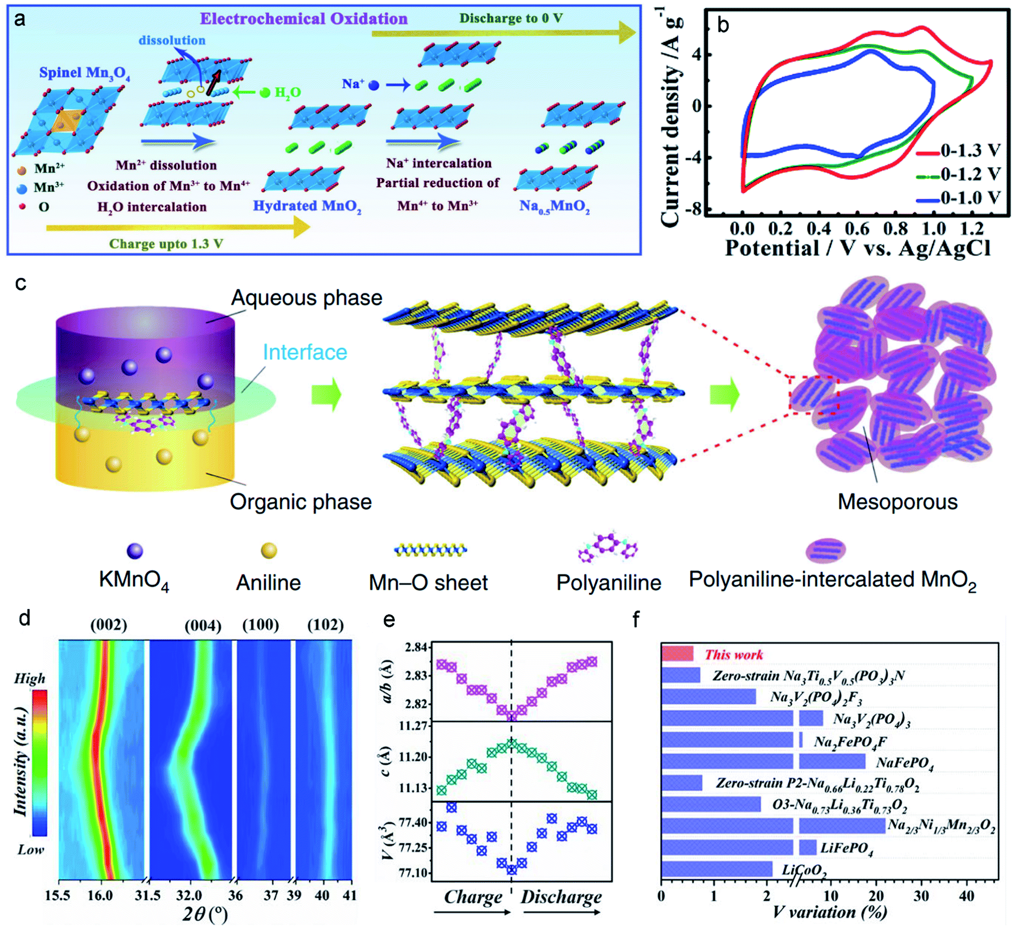 | ||
| Fig. 9 (a) Schematic illustration of the preintercalation process during the electrochemical oxidation. (b) The ion-preintercalation effect on widening the potential windows of layered Na0.5MnO2. Reproduced with permission.126 Copyright 2017 Wiley-VCH. (c) A schematic of the expanded structure by the intercalation of polyaniline (PANI) into MnO2 nanolayers. Reproduced with permission.101 Copyright 2018 Springer Nature. (d) The typical in situ XRD patterns of the Na0.67Mn0.5Co0.5−xFexO2 electrode. (e) The variation of cell parameters c (green points), V (blue points), and a/b (pink points). (f) V variation of Na0.67Mn0.5Co0.5−xFexO2 and several typical sodium-storage cathode materials during the charge/discharge process. Reproduced with permission.127 Copyright 2021 Wiley-VCH. | ||
Aside from enlarging the interlayer spacing, some intercalated ions may have a pinning effect to suppress phase transitions and thus improve the structural stability. In Na-ion batteries, Na+ ions possess a large radius and cause huge lattice changes of more than 20% during the sodiation/desodiation process, inducing a severe phase transition, resulting in more than 30% capacity fading over 100 cycles at the current density of 2C.127 Chu et al.127 reported that intercalated Fe in the Na site acts as a pinning point to suppress slab sliding. The pinning point represents a structural stabilizer that significantly reduces the volume variation to appropriately 0.6% (Fig. 9d and e). This slight structural change confers outstanding structural stability and maintains a smooth channel for fast Na-ion transfer during the electrochemical processes. The ultra-low volume variation is even smaller than those of electrode materials like LiCoO2 and LiFePO4, as shown in Fig. 9f. Consequently, Na-ion batteries fabricated using this improved material can achieve high capacity retention of ∼89.1% over 100 cycles at the current density of 2C. Impressively, 71% capacity can be retained over 1000 cycles at the high current density of 10C.
On the basis of the above introduction, manipulating the interlayered structure via the preintercalation can greatly enlarge the interlayer space and thus facilitate the ions to diffuse in the bulk of the MLO materials, which also enables the MLO materials to provide more active sites to accommodate cations. In addition, the support effect of preintercalated ions/molecules on the interlayered structure can improve the structural stability, guaranteeing long-term cycling stability. Nevertheless, preintercalated ions may have the electrostatic repulsion effect with the inserted ions during the electrochemical processes. Moreover, the stability of supported ions/molecules should be considered. These preintercalated species suffer from issues of extraction of ions/molecules from the host interlayers during the electrochemical processes, which is unavoidable. Such issues eliminate the advantages of manipulating interlayered structures and induce severe structural degradation during the continuous intercalation/de-intercalation of cations. Excessive cation preintercalation would induce the phase transition where the structural reconstruction enables the loss of the fast ionic transport of layered pathways.100 Therefore, to avoid these disadvantages, careful screening of the preintercalated ions/molecules and optimizing their amount are necessary.
4.3 Vacancy introduction
Considering that vacancy engineering can tune the physicochemical properties of MLO materials, it is logical to anticipate that precisely designing vacancies may promote their electrochemical performance. Vacancies involving MLO materials mainly consist of anionic (nonmetal) vacancies, cationic (metal) vacancies, and mixed vacancies. MLO materials usually suffer from severe J–T distortion of the octahedral Mn3+ at low voltages and/or anionic reaction-induced structural evolution at high potentials. Incorporating the vacancies into the TM layer promotes ionic reduction/oxidation and bond length changes, which have a significant effect on the layered structure stability at both low and high potentials.136–140 To determine how vacancies improve the structural stability, Yang et al.128 investigated structural and electrochemical behavior changes by designing vacancy-containing P2-type Na2/3[Zn1/9Mn7/9□1/9]O2 (NZMO-Vac; with vacancies in the TM layer). The low-spin Mn3+ ion content increased after the introduction of vacancies at a low voltage, which was ascribed to the shortened Mn–O bond, as shown in (Fig. 10a). It is well known that high-spin Mn3+ ions are the main reason for the undesirable structural degradation and substantial capacity fading of MLO materials. Thus, increasing the content of low-spin Mn3+ is key to avoiding J–T distortion. Fig. 10b shows the coexistence of 23.6% low-spin Mn3+ and 10.9% high-spin Mn3+ ions in the discharged NZMO-Vac. Meanwhile, the oxygen atoms around the formed vacancies contributed much more charge compensation than those around Zn, accelerating the oxygen redox reaction and enhancing the reversibility of the anionic reaction. In addition, Mn vacancies can provide more ion intercalation sites, giving rise to reduced charge transfer resistance and improved specific capacitance. Correspondingly, NZMO-Vac delivered a much higher capacity than NZMO (204 and 187 mA h g−1 for NZMO-Vac and NZMO, respectively) at 0.02 A g−1 in the first cycle. Moreover, the NZMO-Vac retained 43.4% capacity after 100 cycles, which is better than the 25.6% of NZMO.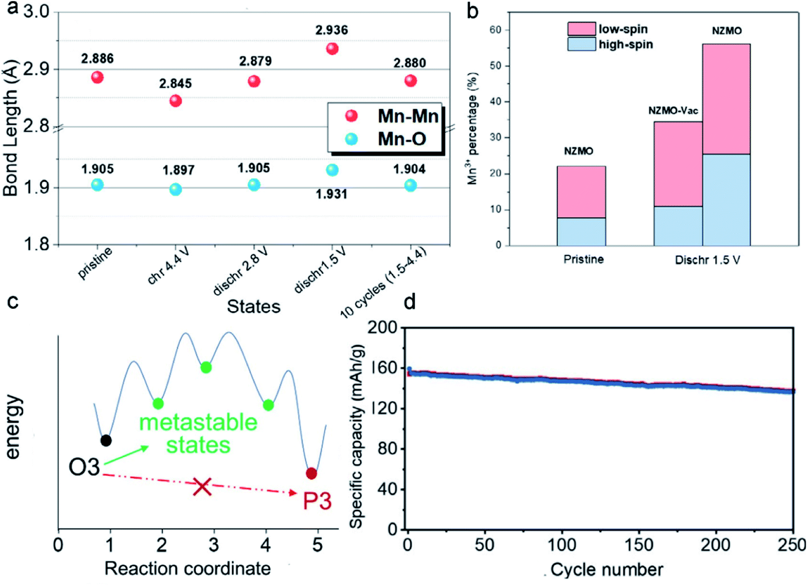 | ||
| Fig. 10 (a) The evolution of bond lengths in the electrochemical processes. (b) The percentages of the low-spin and high-spin Mn3+ ions. Reproduced with permission.128 Copyright 2021 Elsevier. (c) Schematic illustration of the mechanism behind the prevention of the O3–P3 biphasic reaction. (d) Cycling performance of Li1.2[Mn0.66Co0.17Ni0.17]0.8O2 at 125 mA g−1. Reproduced with permission.129 Copyright 2021 Wiley-VCH. | ||
In addition to single vacancies, the introduction of mixed vacancies is also an effective way to suppress structural degradation due to the synergistic effects between anionic and cationic vacancies. In both P2-type and O3-type MLO materials, the irreversible layer gliding causes huge volume changes and significantly jeopardizes the structural stability.141,142 To solve this problem, reducing the net charge of the oxygen (i.e., creating oxygen vacancies) or enabling reversible TM migration during the charging/discharging process is critical. “Reversible” migration implies that TM can move between the TM layer and alkaline layer but does not need to return to the same site each time. Therefore, cationic vacancies can provide many more sites for TM migration. To demonstrate this concept, Xiao et al.129 prepared an Li- and Mn- rich layered cathode material, in which the formation of oxygen vacancies and Mn vacancies was simultaneous. The results of a combination of computational simulations and systematic characterizations demonstrated that the mixed vacancies enabled the TM to migrate to the tetrahedral sites of the Na layer during desodiation and move back during sodiation. The TM migration suppressed a complete O3–P3 phase transition by increasing the energy barriers and stabilized the performance. Fig. 10c shows the proposed energy evolution during the O3–P3 two-phase reaction by manipulating TM migrations. Such metastable states can immobilize the structure and inhibit the transition to global P stacking. Correspondingly, the Li- and Mn-rich layered cathode material delivered 86% capacity retention after 250 cycles (Fig. 10d). In addition, although the interlayer spacing decreased to 5.0 Å, the diffusion kinetics of Na+ ions was not affected, which was attributed to the formation of oxygen vacancies and the distortion of the metal oxide layer.
As described above, the incorporation of Mn and/or O ion vacancies in MLO materials promotes ion-reduction/oxidation and bond length changes, which significantly increase the percentage of low-spin Mn3+ and provide more sites for the reversible migration of Mn ions. It should be noted that the introduction of vacancies can alter the electronic structure and bonding energy in MLO materials. Too high amount of vacancies may sacrifice the conductivity of materials and structural stability. However, how to achieve precise and optimum vacancy concentration is a critical issue in the current synthesis process. Correspondingly, developing new synthesis methods to accurately control the vacancy concentration is necessary. Furthermore, advanced characterization methods to monitor the generation process of vacancies are also needed.
4.4 Novel structural design
Structural stability during the electrochemical reaction is an indispensable requirement of MLO materials. Both O3-type and P2-type NaxMnO2 undergo the gliding of oxygen layers during the electrochemical process and suffer from J–T distortion, leading to structural deterioration and undesirable performance. Birnessite-NaxMnO2·nH2O possesses a much larger interlayer spacing (∼7 Å) than the O2 (∼5 Å) and P3 (∼5 Å) phase, increasing the rate of Na+ diffusion. In contrast, no oxygen layer gliding occurs in Birnessite-NaxMnO2·nH2O during oxidation due to the pillar effect of crystal water; the corresponding layered structure can offer protection against J–T distortion and structural degradation.143,144 Nevertheless, it should be taken into account that crystal water in the interlayer may limit Na accommodation and hinder Na+ diffusion. Meanwhile, crystal water is extracted in the oxidation process, and the presence of water in the electrolyte greatly impacts its stability and accelerates decomposition.To address these issues, Xia et al. designed a novel monoclinic polymorph NaMnO2−y−δ(OH)2y with the coexistence of the O′3 and H′3.47 In sharp contrast to the monoclinic, O3-, and P2-NaxMnO2, the monoclinic polymorph NaMnO2−y−δ(OH)2y has a larger interlayer distance (∼7 Å), which greatly enhances the kinetics of Na+ ion diffusion. The large interlayer space is attributed to the simultaneous formation of O′3 and H′3 phases with six-coordinate octahedral sites and eight-coordinate hexahedral sites, respectively. It was found that the generated O vacancy in this material can reduce the bandgap, suggesting the enhanced electronic conductivity of NaMnO2−y−δ(OH)2y. Therefore, NaMnO2−y−δ(OH)2y with large interlayered spacing and high electronic conductivity accelerates the electron and ion transport in the electrode, which enables the NaMnO2−y−δ (OH)2y electrode to maintain a large capacity of 156 mA h g−1 even at the current density of 50C, outperforming the previously reported data in this field. In addition, the reduced distortion of Mn–O and the small β angle in NaMnO2−y−δ(OH)2y are beneficial to suppress the J–T distortion and minimize the volume change during electrochemical processes (Fig. 11a). These attributes explain why NaMnO2−y−δ(OH)2y can achieve superior structural stability and excellent cycle performance. As a result, the prepared NaMnO2−y−δ(OH)2y electrode achieved outstanding cycling stability (94.6% capacity retention at 10C over 1000 cycles) than the Birnessite NaMnO2−y−δ (OH)2y·0.61H2O (78% capacity retention at 10C over 1000 cycles).
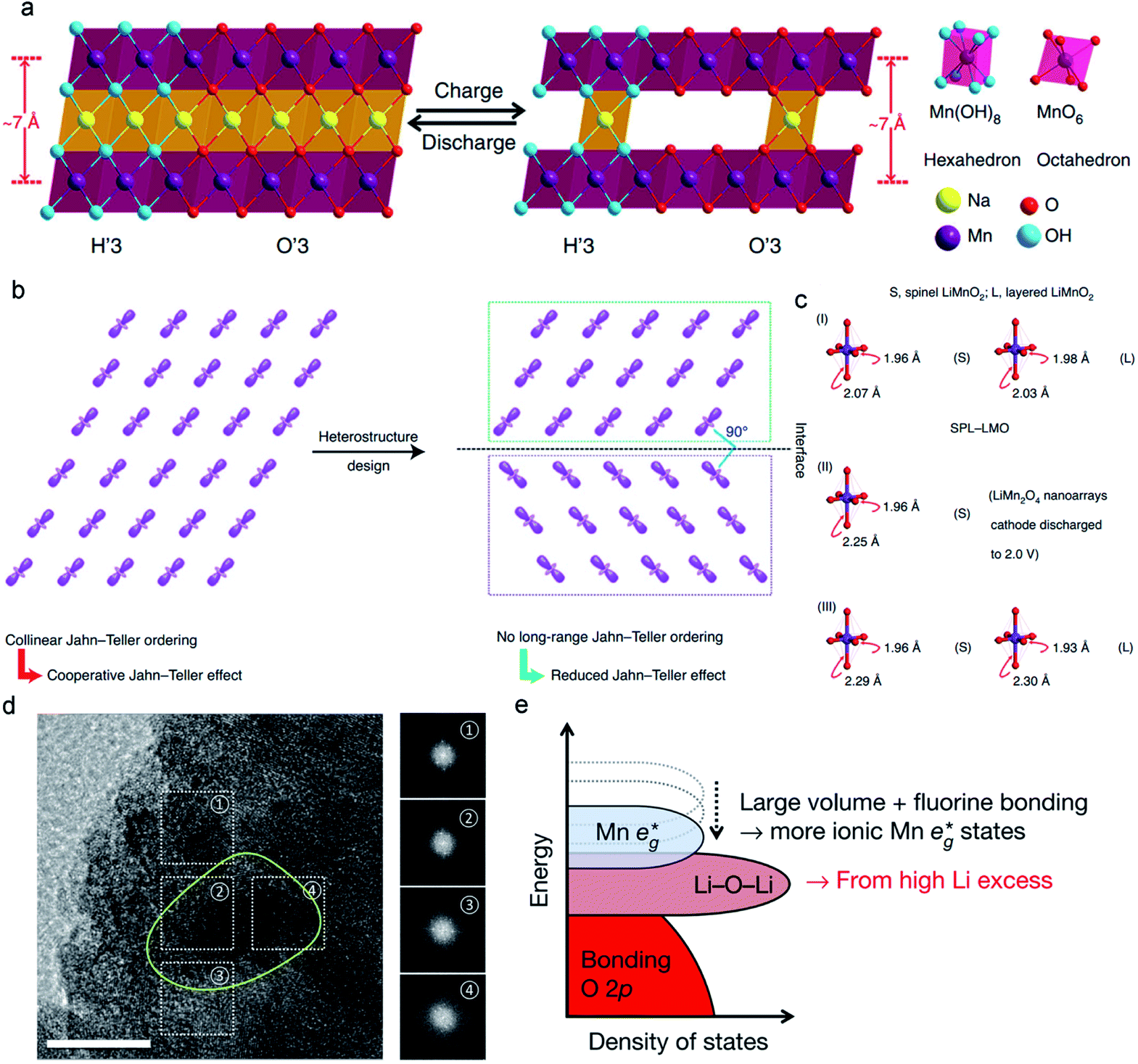 | ||
| Fig. 11 (a) Reversible crystal structure change of the monoclinic H′3/O′3 NaMnO2−y−δ(OH)2y in the electrochemical processes. Reproduced with permission.47 Copyright 2018 Springer Nature. (b) Alleviating Jahn–Teller distortion by interfacial structure manipulation in spinel–layered LiMnO2. (c) Bond lengths of MnO6 octahedra in spinel–layered LiMnO2, spinel LiMnO2, and monoclinic LiMnO2. Reproduced with permission.44 Copyright 2021 Springer Nature. (d) A high-magnification TEM image of polycrystalline Li2Mn2/3Nb1/3O2F (yellow circle). Reproduced with permission.130 Copyright 2018 Springer Nature. | ||
Designing novel interface structures is also effective in suppressing J–T distortion. Considering the orbital ordering in Mn3+-containing MLO materials, such as LiMnO2, which can generate the collinear J–T order, the strong cooperative J–T effect may cause a large volume change and promote structural degradation (Fig. 11b). To eliminate this cooperative J–T effect, Xia et al.44 designed a unique heterostructure of LiMnO2. The heterostructure comprised layered and spinel domains with various orientations for J–T distortion, which can effectively disrupt the long-range collinear J–T ordering for either the spinel phase or the layered phase in the heterostructure. Fig. 11c compares the axial Mn–O bond elongation in this heterostructure with those in spinel and monoclinic LiMnO2. The heterostructure increased the axial Mn–O bonds from 1.96 to 2.07 Å in spinel LiMnO2 and 1.98 to 2.03 Å in monoclinic LiMnO2, which corresponds to 5.5% and 2.5% distorted degrees, respectively. For layered LiMnO2 and spinel Li2Mn2O4,69,145 the distortion degrees were 18.0% and 15.9%, respectively, much higher than the corresponding phase in the heterostructure. Therefore, the layered–spinel heterostructure with controlled interfacial orbital ordering significantly suppressed J–T distortion. The electrochemical results demonstrated that the LiMnO2 heterostructure cathode delivered high specific capability ∼254.3 mA h g−1 with 97% coulombic efficiency. Furthermore, such a heterostructure achieved a high specific capacity of 183.6 mA h g−1 at 12C. Unprecedented cycling stability with ∼90.4% capacity retention over 2000 cycles was achieved, demonstrating the significant effect of interfacial engineering on mitigating J–T distortion.
Cation-disordered lithium-rich MLO materials are another example of a novel structure.146 Lee et al.130 prepared a new cation-disordered (disordered rock-salt structure) material Li2Mn2/3Nb1/3O2F by manipulating the layered phase of Li2MnO3 (Fig. 11d). The disordered rock-salt structure, originating from a layered structure, can generate more 0 TM channels.147 This diffusion channel has a low migration barrier, giving rise to fast Li+ diffusion kinetics. Furthermore, with cation and anion substitution, the disordered rock-salt Li-rich cathodes could deliver a high capacity (>300 mA h g−1), mainly from the Mn2+/Mn4+ double electron reaction (Fig. 11e). This Mn2+/Mn4+ double redox effectively suppresses the problems associated with O redox by reducing the anionic redox reaction content.
In short, novel structural design shows notable effectiveness in manipulating the localized structure to suppress the J–T effect, providing stable units in localized regions and thus effectively eliminating electrochemical degradation. Nevertheless, novel structural design faces great challenges, countering which needs an in-depth understanding of the structure–property relationships in MLO materials. Additionally, accurately manipulating the structure at the atomic level is difficult, which is not suited to large-scale applications in most cases.
5. Conclusion and future perspectives
In recent decades, endeavors to build a holistic understanding of the impact of electrochemistry on the structural degradation of MLO materials have experienced a revival. Substantial progress has been made in the field of MLO materials for various energy storage technologies. All in all, developing MLO materials with high capacity, high voltage, high stability, and high rate in energy storage is our target. To reach this target, the irreversible phase transformation, Mn dissolution/disproportionation reaction, interfacial degradation arising from Mn2+, and crack formation induced by J–T distortion must be better understood at the atomic level. From the perspective of structure–property relationships in MLO materials, this review comprehensively summarizes structure and property optimization for high-efficiency energy storage. First, elemental doping can restrain the elongated bonds and stabilize the metastable structure to inhibit J–T distortion during the electrochemical process, preventing structural degradation. Second, the interlayer structure can be manipulated by preintercalating ions or molecules, which serve as pillars against lattice change and endow MLO materials with a robust layered structure and/or large interlayer spacing to accommodate J–T distortion, resulting in fast diffusion kinetics and high cycling stability. Third, the incorporation of Mn and/or O ion vacancies in MLO materials promotes ion-reduction/oxidation and bond length changes, which significantly increase the percentage of low-spin Mn3+ and provide more sites for the reversible migration of Mn ions. Finally, novel structural design shows notable effectiveness in manipulating the localized structure to suppress the J–T effect, providing stable units in localized regions and thus effectively eliminating electrochemical degradation.Although various strategies have paved effective pathways to suppress electrochemical degradation, it is still difficult to thoroughly disentangle the issues raised above. Additional research efforts are needed to develop methods for stabilizing the crystal structure during electrochemical processes to suppress capacity degradation in the representative MLO systems. Our suggestions are as follows:
(1) Coupling various strategies to induce synergistic effects for high-performance MLO materials. Each strategy may have a limited effect on suppressing the degradation of MLO cathodes. In this case, integrating various strategies to exploit their synergistic effects may be worth exploring. For example, combining doping and interlayer manipulation may realize robust structural stability and fast diffusion kinetics.
(2) Developing novel MLO materials with stable structures. Presently, most MLO materials still have structural issues and are sensitive to air containing water vapor. It is critically necessary to innovate MLO materials with highly stable localized structures and microstructures by modulating the electronic states and tailoring the crystal domains. In addition, advanced machine learning and theoretical calculations can be applied to design and develop high-performance MLO materials. With improved computational analyses, it is possible to gain some quantitative comprehension of the effect of each adverse factor on structural stability using qualitative constraints in simulations.
(3) Realizing accurate MLO cathode characterization and comprehensively elucidating the structure–property correlations. Electrochemical energy storage devices store energy through electrochemical reactions. However, the understanding of the intrinsic electrochemical reaction mechanisms in MLO materials is still limited due to the complexity of each energy storage system and the effects of electrolytes, conductive carbon additives, and binders. In this regard, powerful characterization techniques, such as in situ transmission electron microscopy, in situ X-ray absorption spectroscopy, and electrochemical quartz crystal microbalance analysis, are indispensable to distinguish the dynamic structural evolution and electrochemical behaviors of MLO cathodes and comprehensively understand their structure–property correlations.
In conclusion, a comprehensive understanding of the electrochemical degradation mechanisms at the atomic level is essential for developing high-performance MLO cathodes, as is systematically outlined in this review. Although numerous challenges remain, the future is bright thanks to the tremendous endeavors to elucidate J–T distortion and the continual development of effective strategies, advanced characterization techniques, artificial intelligence, and theoretical calculations. We hope that the synergistic application of experiments and computational modeling will dramatically improve our understanding of the chemical degradation mechanisms and the electrochemical performance of energy storage systems based on MLO cathodes.
Conflicts of interest
The authors declare no conflict of interest.Acknowledgements
T. Z. and H. X. acknowledge the support from the National Natural Science Foundation of China (No. 52072179, 52061135201, 51772154, and 51972174), Natural Science Foundation of Jiangsu Province (No. BK20200073), and the Fundamental Research Funds for the Central Universities (No. 30919011108 and 30920041118).References
- G. Harper, R. Sommerville, E. Kendrick, L. Driscoll, P. Slater, R. Stolkin, A. Walton, P. Christensen, O. Heidrich and S. Lambert, Nature, 2019, 575, 75–86 CrossRef CAS PubMed.
- P. P. Lopes and V. R. Stamenkovic, Science, 2020, 369, 923–924 CrossRef CAS PubMed.
- X. Chen, X. Shen, T. Z. Hou, R. Zhang, H. J. Peng and Q. Zhang, Chem, 2020, 6, 2242–2256 CAS.
- S. Sun, C. Z. Zhao, H. Yuan, Y. Lu, J. K. Hu, J. Q. Huang and Q. Zhang, Mater. Futures, 2021, 1, 012101 CrossRef.
- Y. Lu, C. Z. Zhao, R. Zhang, H. Yuan, L. P. Hou, Z. H. Fu, X. Chen, J. Q. Huang and Q. Zhang, Sci. Adv., 2021, 7, eabi5520 CrossRef CAS PubMed.
- Q. Guo, S. Sun, K. i. Kim, H. Zhang, X. Liu, C. Yan and H. Xia, Carbon Energy, 2021, 3, 440–448 CrossRef CAS.
- S. Sun, B. Liu, H. Zhang, Q. Guo, Q. Xia, T. Zhai and H. Xia, Adv. Energy Mater., 2021, 11, 2003599 CrossRef CAS.
- Q. Xia, Q. Zhang, S. Sun, F. Hussain, C. Zhang, X. Zhu, F. Meng, K. Liu, H. Geng and J. Xu, Adv. Mater., 2021, 33, 2003524 CrossRef CAS PubMed.
- Q. Guo, K. I. Kim, S. Li, A. M. Scida, P. Yu, S. K. Sandstrom, L. Zhang, S. Sun, H. Jiang and Q. Ni, ACS Energy Lett., 2021, 6, 459–467 CrossRef CAS.
- S. Sun, D. Rao, T. Zhai, Q. Liu, H. Huang, B. Liu, H. Zhang, L. Xue and H. Xia, Adv. Mater., 2020, 32, 2005344 CrossRef CAS PubMed.
- M. Jiang, D. L. Danilov, R. A. Eichel and P. H. Notten, Adv. Energy Mater., 2021, 11, 2103005 CrossRef CAS.
- M. H. Han, E. Gonzalo, G. Singh and T. Rojo, Energy Environ. Sci., 2015, 8, 81–102 RSC.
- L. Xue, S. Li, T. Shen, M. Ni, C. Qiu, S. Sun, H. Geng, X. Zhu and H. Xia, Energy Storage Mater., 2020, 32, 272–280 CrossRef.
- C. Grey and J. Tarascon, Nat. Mater., 2017, 16, 45–56 CrossRef PubMed.
- L. Fang, J. Xu, S. Sun, B. Lin, Q. Guo, D. Luo and H. Xia, Small, 2019, 15, 1804806 CrossRef PubMed.
- Q. Xia, S. Sun, J. Xu, F. Zan, J. Yue, Q. Zhang, L. Gu and H. Xia, Small, 2018, 14, 1804149 CrossRef PubMed.
- M. Dixit, B. Markovsky, F. Schipper, D. Aurbach and D. T. Major, J. Phys. Chem. C, 2017, 121, 22628–22636 CrossRef CAS.
- X. Shan, F. Guo, D. S. Charles, Z. Lebens-Higgins, S. Abdel Razek, J. Wu, W. Xu, W. Yang, K. L. Page and J. C. Neuefeind, Nat. Commun., 2019, 10, 4975 CrossRef PubMed.
- S. Boyd, K. Ganeshan, W. Y. Tsai, T. Wu, S. Saeed, D. e. Jiang, N. Balke, A. C. van Duin and V. Augustyn, Nat. Mater., 2021, 20, 1689–1694 CrossRef CAS PubMed.
- R. Jia, J. Yue, Q. Xia, J. Xu, X. Zhu, S. Sun, T. Zhai and H. Xia, Energy Storage Mater., 2018, 13, 303–311 CrossRef.
- C. Delmas, C. Fouassier and P. Hagenmuller, Physica B+C, 1980, 99, 81–85 CrossRef CAS.
- X. Cao, Y. Qiao, M. Jia, P. He and H. Zhou, Adv. Energy Mater., 2022, 12, 2003972 CrossRef CAS.
- S. Zhu, W. Huo, X. Liu and Y. Zhang, Nanoscale Adv., 2020, 2, 37–54 RSC.
- B. Lin, X. Zhu, L. Fang, X. Liu, S. Li, T. Zhai, L. Xue, Q. Guo, J. Xu and H. Xia, Adv. Mater., 2019, 31, 1900060 CrossRef PubMed.
- K. Mizushima, P. Jones, P. Wiseman and J. B. Goodenough, Mater. Res. Bull., 1980, 15, 783–789 CrossRef CAS.
- J. Dunitz and L. Orgel, J. Phys. Chem. Solids, 1957, 3, 20–29 CrossRef CAS.
- M. H. Alfaruqi, J. Gim, S. Kim, J. Song, D. T. Pham, J. Jo, Z. Xiu, V. Mathew and J. Kim, Electrochem. Commun., 2015, 60, 121–125 CrossRef CAS.
- Y. Xu, J. Ma, T. Jiang, H. Ding, W. Wang, M. Wang, X. Zheng, J. Sun, Y. Yuan and M. Chuai, Energy Storage Mater., 2022, 47, 113–121 CrossRef.
- L. Liu, Y. C. Wu, L. Huang, K. Liu, B. Duployer, P. Rozier, P. L. Taberna and P. Simon, Adv. Energy Mater., 2021, 11, 2101287 CrossRef CAS.
- K. W. Nam, S. Kim, S. Lee, M. Salama, I. Shterenberg, Y. Gofer, J. S. Kim, E. Yang, C. S. Park and J. S. Kim, Nano Lett., 2015, 15, 4071–4079 CrossRef CAS PubMed.
- X. Sun, V. Duffort, B. L. Mehdi, N. D. Browning and L. F. Nazar, Chem. Mater., 2016, 28, 534–542 CrossRef CAS.
- H. A. Jahn and E. Teller, Proc. R. Soc. A: Math. Phys. Eng. Sci., 1937, 161, 220–235 CAS.
- G. Ceder and S. Mishra, Electrochem. Solid-State, 1999, 2, 550 CrossRef CAS.
- K. Zhang, D. Kim, Z. Hu, M. Park, G. Noh, Y. Yang, J. Zhang, V. W. h. Lau, S. L. Chou and M. Cho, Nat. Commun., 2019, 10, 5203 CrossRef CAS PubMed.
- M. D. Radin and A. Van der Ven, Chem. Mater., 2018, 30, 607–618 CrossRef CAS.
- C. Wang, L. Liu, S. Zhao, Y. Liu, Y. Yang, H. Yu, S. Lee, G. H. Lee, Y. M. Kang and R. Liu, Nat. Commun., 2021, 12, 2256 CrossRef CAS PubMed.
- W. Zuo, X. Liu, J. Qiu, D. Zhang, Z. Xiao, J. Xie, F. Ren, J. Wang, Y. Li and G. F. Ortiz, Nat. Commun., 2021, 12, 4903 CrossRef CAS PubMed.
- Y. S. Xu, Y. N. Zhou, Q. H. Zhang, M. Y. Qi, S. J. Guo, J. M. Luo, Y. G. Sun, L. Gu, A. M. Cao and L. J. Wan, Chem. Eng. J., 2021, 412, 128735 CrossRef CAS.
- K. Lei, Z. Zhu, Z. Yin, P. Yan, F. Li and J. Chen, Chem, 2019, 5, 3220–3231 CAS.
- P. Yan, J. Zheng, Z. K. Tang, A. Devaraj, G. Chen, K. Amine, J. G. Zhang, L. M. Liu and C. Wang, Nat. Nanotechnol., 2019, 14, 602–608 CrossRef CAS PubMed.
- Q. Zhao, A. Song, S. Ding, R. Qin, Y. Cui, S. Li and F. Pan, Adv. Mater., 2020, 32, 2002450 CrossRef CAS PubMed.
- Q. Guo, S. Li, X. Liu, H. Lu, X. Chang, H. Zhang, X. Zhu, Q. Xia, C. Yan and H. Xia, Adv. Sci., 2020, 7, 1903246 CrossRef CAS PubMed.
- H. Li, W. Zhang, K. Sun, J. Guo, K. Yuan, J. Fu, T. Zhang, X. Zhang, H. Long and Z. Zhang, Adv. Energy Mater., 2021, 11, 2100867 CrossRef CAS.
- X. Zhu, F. Meng, Q. Zhang, L. Xue, H. Zhu, S. Lan, Q. Liu, J. Zhao, Y. Zhuang and Q. Guo, Nat. Sustain., 2021, 4, 392–401 CrossRef.
- Z. Lu and J. Dahn, J. Electrochem. Soc., 2001, 148, A237 CrossRef CAS.
- Y. Zuo, B. Li, N. Jiang, W. Chu, H. Zhang, R. Zou and D. Xia, Adv. Mater., 2018, 30, 1707255 CrossRef PubMed.
- H. Xia, X. Zhu, J. Liu, Q. Liu, S. Lan, Q. Zhang, X. Liu, J. K. Seo, T. Chen and L. Gu, Nat. Commun., 2018, 9, 5100 CrossRef PubMed.
- X. Ma, H. Chen and G. Ceder, J. Electrochem. Soc., 2011, 158, A1307 CrossRef CAS.
- Y. Zhang, X. Cui, Y. Liu, S. Cheng, P. Cui, Y. Wu, Z. Sun, Z. Shao, J. Fu and E. Xie, J. Energy Chem., 2022, 67, 225–232 CrossRef.
- Z. Shi, J. Wu, M. Ni, Q. Guo, F. Zan and H. Xia, Mater. Res. Bull., 2021, 144, 111475 CrossRef CAS.
- Z. Shi, L. Xue, J. Wu, Q. Guo, Q. Xia, M. Ni, P. Wang, S. V. Savilov, S. M. Aldoshin and F. Zan, J. Electrochem. Soc., 2021, 168, 120549 CrossRef.
- M. Wang and S. Yagi, J. Alloys Compd., 2020, 820, 153135 CrossRef CAS.
- P. Almodóvar, D. A. Giraldo, J. Chancón, I. Álvarez-Serrano and M. L. López, ChemElectroChem, 2020, 7, 2102–2106 CrossRef.
- S. Chong, Y. Wu, C. Liu, Y. Chen, S. Guo, Y. Liu and G. Cao, Nano Energy, 2018, 54, 106–115 CrossRef CAS.
- J. Billaud, R. J. Clément, A. R. Armstrong, J. Canales-Vázquez, P. Rozier, C. P. Grey and P. G. Bruce, J. Am. Chem. Soc., 2014, 136, 17243–17248 CrossRef CAS PubMed.
- D. H. Seo, J. Lee, A. Urban, R. Malik, S. Kang and G. Ceder, Nat. Chem., 2016, 8, 692–697 CrossRef CAS PubMed.
- M. D. Radin, J. Vinckeviciute, R. Seshadri and A. van der Ven, Nat. Energy, 2019, 4, 639–646 CrossRef CAS.
- J. Wang, J. G. Wang, H. Liu, C. Wei and F. Kang, J. Mater. Chem. A, 2019, 7, 13727–13735 RSC.
- C. Costentin, T. R. Porter and J. M. Savéant, ACS Appl. Mater. Interfaces, 2017, 9, 8649–8658 CrossRef CAS PubMed.
- W. Wei, X. Cui, W. Chen and D. G. Ivey, Chem. Soc. Rev., 2011, 40, 1697–1721 RSC.
- M. Mateos, N. Makivic, Y. s. Kim, B. Limoges and V. Balland, Adv. Energy Mater., 2020, 10, 2000332 CrossRef CAS.
- L. Liu, L. Su, Y. Lu, Q. Zhang, L. Zhang, S. Lei, S. Shi, M. D. Levi and X. Yan, Adv. Funct. Mater., 2019, 29, 1806778 CrossRef.
- G. Vitins and K. West, J. Electrochem. Soc., 1997, 144, 2587 CrossRef CAS.
- M. Tabuchi, K. Ado, H. Kobayashi, H. Kageyama, C. Masquelier, A. Kondo and R. Kanno, J. Electrochem. Soc., 1998, 145, L49 CrossRef CAS.
- S. J. Hwang, H. S. Park, J. H. Choy and G. Campet, Chem. Mater., 2000, 12, 1818–1826 CrossRef CAS.
- J. Paulsen, C. Thomas and J. Dahn, J. Electrochem. Soc., 1999, 146, 3560 CrossRef CAS.
- Q. Chen, S. Sun, T. Zhai, M. Yang, X. Zhao and H. Xia, Adv. Energy Mater., 2018, 8, 1800054 CrossRef.
- J. Reimers, E. W. Fuller, E. Rossen and J. Dahn, J. Electrochem. Soc., 1993, 140, 3396 CrossRef CAS.
- A. R. Armstrong and P. G. Bruce, Nature, 1996, 381, 499–500 CrossRef CAS.
- C. Delmas, D. Carlier and M. Guignard, Adv. Energy Mater., 2021, 11, 2001201 CrossRef CAS.
- H. Ji, J. Wu, Z. Cai, J. Liu, D. H. Kwon, H. Kim, A. Urban, J. K. Papp, E. Foley and Y. Tian, Nat. Energy, 2020, 5, 213–221 CrossRef CAS.
- C. Zuo, Z. Hu, R. Qi, J. Liu, Z. Li, J. Lu, C. Dong, K. Yang, W. Huang and C. Chen, Adv. Energy Mater., 2020, 10, 2000363 CrossRef CAS.
- A. Manthiram, Nat. Commun., 2020, 11, 1550 CrossRef CAS PubMed.
- A. D. Robertson, A. R. Armstrong and P. G. Bruce, Chem. Mater., 2001, 13, 2380–2386 CrossRef CAS.
- A. R. Armstrong, A. D. Robertson, R. Gitzendanner and P. G. Bruce, J. Solid State Chem., 1999, 145, 549–556 CrossRef CAS.
- C. Fouassier, G. Matejka, J. M. Reau and P. Hagenmuller, J. Solid State Chem., 1973, 6, 532–537 CrossRef CAS.
- A. M. Abakumov, A. A. Tsirlin, I. Bakaimi, G. Van Tendeloo and A. Lappas, Chem. Mater., 2014, 26, 3306–3315 CrossRef CAS.
- O. Velikokhatnyi, C. C. Chang and P. Kumta, J. Electrochem. Soc., 2003, 150, A1262 CrossRef CAS.
- R. Hoppe, G. Brachtel and M. Jansen, Z. Anorg. Allg. Chem., 1975, 417, 1–10 CrossRef CAS.
- X. Chen, Y. Wang, K. Wiaderek, X. Sang, O. Borkiewicz, K. Chapman, J. LeBeau, J. Lynn and X. Li, Adv. Funct. Mater., 2018, 28, 1805105 CrossRef.
- X. Li, X. Ma, D. Su, L. Liu, R. Chisnell, S. P. Ong, H. Chen, A. Toumar, J. C. Idrobo and Y. Lei, Nat. Mater., 2014, 13, 586–592 CrossRef CAS PubMed.
- J. Sun, C. Sheng, X. Cao, P. Wang, P. He, H. Yang, Z. Chang, X. Yue and H. Zhou, Adv. Funct. Mater., 2022, 32, 2110295 CrossRef CAS.
- W. E. Gent, K. Lim, Y. Liang, Q. Li, T. Barnes, S. J. Ahn, K. H. Stone, M. McIntire, J. Hong and J. H. Song, Nat. Commun., 2017, 8, 2091 CrossRef PubMed.
- J. S. Kim, C. S. Johnson, J. T. Vaughey, M. M. Thackeray, S. A. Hackney, W. Yoon and C. P. Grey, Chem. Mater., 2004, 16, 1996–2006 CrossRef CAS.
- M. M. Thackeray, S. H. Kang, C. S. Johnson, J. T. Vaughey, R. Benedek and S. Hackney, J. Mater. Chem., 2007, 17, 3112–3125 RSC.
- G. Assat and J. M. Tarascon, Nat. Energy, 2018, 3, 373–386 CrossRef CAS.
- D. Eum, B. Kim, S. J. Kim, H. Park, J. Wu, S. P. Cho, G. Yoon, M. H. Lee, S. K. Jung and W. Yang, Nat. Mater., 2020, 19, 419–427 CrossRef CAS PubMed.
- Q. Chu, X. Wang, X. Zhang, Q. Li and X. Liu, Inorg. Chem., 2011, 50, 2049–2051 CrossRef CAS PubMed.
- M. Gu, I. Belharouak, J. Zheng, H. Wu, J. Xiao, A. Genc, K. Amine, S. Thevuthasan, D. R. Baer and J. G. Zhang, ACS Nano, 2013, 7, 760–767 CrossRef CAS PubMed.
- P. F. Wang, Y. You, Y. X. Yin and Y. G. Guo, Adv. Energy Mater., 2018, 8, 1701912 CrossRef.
- A. Singer, M. Zhang, S. Hy, D. Cela, C. Fang, T. Wynn, B. Qiu, Y. Xia, Z. Liu and A. Ulvestad, Nat. Energy, 2018, 3, 641–647 CrossRef CAS.
- G. Assat, D. Foix, C. Delacourt, A. Iadecola, R. Dedryvère and J.-M. Tarascon, Nat. Commun., 2017, 8, 2219 CrossRef PubMed.
- Q. Li, D. Ning, D. Zhou, K. An, D. Wong, L. Zhang, Z. Chen, G. Schuck, C. Schulz and Z. Xu, J. Mater. Chem. A, 2020, 8, 7733–7745 RSC.
- M. Freire, N. V. Kosova, C. Jordy, D. Chateigner, O. Lebedev, A. Maignan and V. Pralong, Nat. Mater., 2016, 15, 173–177 CrossRef CAS PubMed.
- S. Myeong, W. Cho, W. Jin, J. Hwang, M. Yoon, Y. Yoo, G. Nam, H. Jang, J. G. Han and N. S. Choi, Nat. Commun., 2018, 9, 3285 CrossRef PubMed.
- P. Liu, H. Zhang, W. He, T. Xiong, Y. Cheng, Q. Xie, Y. Ma, H. Zheng, L. Wang and Z. Z. Zhu, J. Am. Chem. Soc., 2019, 141, 10876–10882 CrossRef CAS PubMed.
- Y. Koyama, I. Tanaka, M. Nagao and R. Kanno, J. Power Sources, 2009, 189, 798–801 CrossRef CAS.
- M. H. Alfaruqi, S. Islam, D. Y. Putro, V. Mathew, S. Kim, J. Jo, S. Kim, Y. K. Sun, K. Kim and J. Kim, Electrochim. Acta, 2018, 276, 1–11 CrossRef CAS.
- Z. Liu, G. Fang, L. Qin, X. Cao, J. Zhou, A. Pan, S. Wang and S. Liang, Prog. Mater. Sci., 2021, 100911 Search PubMed.
- X. Zhao, L. Mao, Q. Cheng, F. Liao, G. Yang, X. Lu and L. Chen, Energy Storage Mater., 2021, 38, 397–437 CrossRef.
- J. Huang, Z. Wang, M. Hou, X. Dong, Y. Liu, Y. Wang and Y. Xia, Nat. Commun., 2018, 9, 2906 CrossRef PubMed.
- B. Song, J. I. Choi, Y. Zhu, Z. Geng, L. Zhang, Z. Lin, C. c. Tuan, K.-s. Moon and C. p. Wong, Chem. Mater., 2016, 28, 9110–9121 CrossRef CAS.
- H. Y. Asl and A. Manthiram, Science, 2020, 369, 140–141 CrossRef CAS PubMed.
- C. Wang, L. Xing, J. Vatamanu, Z. Chen, G. Lan, W. Li and K. Xu, Nat. Commun., 2019, 10, 3423 CrossRef PubMed.
- J. Yang, S. Muhammad, M. R. Jo, H. Kim, K. Song, D. A. Agyeman, Y. I. Kim, W. S. Yoon and Y. M. Kang, Chem. Soc. Rev., 2016, 45, 5717–5770 RSC.
- A. R. Armstrong, N. Dupre, A. J. Paterson, C. P. Grey and P. G. Bruce, Chem. Mater., 2004, 16, 3106–3118 CrossRef CAS.
- M. R. Jo, Y. Kim, J. Yang, M. Jeong, K. Song, Y. I. Kim, J. M. Lim, M. Cho, J. H. Shim and Y. M. Kim, Nat. Commun., 2019, 10, 3385 CrossRef PubMed.
- J. Reed, G. Ceder and A. van der Ven, Electrochem. Solid-State, 2001, 4, A78 CrossRef CAS.
- J. Reed and G. Ceder, Chem. Rev., 2004, 104, 4513–4534 CrossRef CAS PubMed.
- S. Sharifi-Asl, V. Yurkiv, A. Gutierrez, M. Cheng, M. Balasubramanian, F. Mashayek, J. Croy and R. Shahbazian-Yassar, Nano Lett., 2019, 20, 1208–1217 CrossRef PubMed.
- C. Zhan, T. Wu, J. Lu and K. Amine, Energy Environ. Sci., 2018, 11, 243–257 RSC.
- N. Kumagai, S. Komaba, Y. Kataoka and M. Koyanagi, Chem. Lett., 2000, 29, 1154–1155 CrossRef.
- C. Delacourt, A. Kwong, X. Liu, R. Qiao, W. Yang, P. Lu, S. Harris and V. Srinivasan, J. Electrochem. Soc., 2013, 160, A1099 CrossRef CAS.
- S. Komaba, N. Kumagai and Y. Kataoka, Electrochim. Acta, 2002, 47, 1229–1239 CrossRef CAS.
- J. Wandt, A. Freiberg, R. Thomas, Y. Gorlin, A. Siebel, R. Jung, H. A. Gasteiger and M. Tromp, J. Mater. Chem. A, 2016, 4, 18300–18305 RSC.
- X. Xiao, Z. Liu, L. Baggetto, G. M. Veith, K. L. More and R. R. Unocic, Phys. Chem. Chem. Phys., 2014, 16, 10398–10402 RSC.
- P. Yan, J. Zheng, M. Gu, J. Xiao, J. G. Zhang and C. M. Wang, Nat. Commun., 2017, 8, 14101 CrossRef CAS PubMed.
- C. J. Chen, W. K. Pang, T. Mori, V. K. Peterson, N. Sharma, P.-H. Lee, S. h. Wu, C. C. Wang, Y. F. Song and R. S. Liu, J. Am. Chem. Soc., 2016, 138, 8824–8833 CrossRef CAS PubMed.
- P. Yan, J. Zheng, J. Zheng, Z. Wang, G. Teng, S. Kuppan, J. Xiao, G. Chen, F. Pan and J. G. Zhang, Adv. Energy Mater., 2016, 6, 1502455 CrossRef.
- F. Lin, I. M. Markus, D. Nordlund, T. C. Weng, M. D. Asta, H. L. Xin and M. M. Doeff, Nat. Commun., 2014, 5, 3529 CrossRef PubMed.
- X. Cui, S. Wang, X. Ye, X. Fan, C. Gao, Y. Quan, S. Wen, X. Cai, J. Huang and S. Li, Energy Storage Mater., 2022, 45, 1153–1164 CrossRef.
- S. Zhou, G. Wang, W. Tang, Y. Xiao and K. Yan, Electrochim. Acta, 2018, 261, 565–577 CrossRef CAS.
- H. Zhu, Q. Li, X. Gong, K. Cao and Z. Chen, Crystals, 2018, 8, 425 CrossRef.
- Y. Zhao, Q. Fang, X. Zhu, L. Xue, M. Ni, C. Qiu, H. Huang, S. Sun, S. Li and H. Xia, J. Mater. Chem. A, 2020, 8, 8969–8978 RSC.
- Y. Wang, X. Wang, X. Li, R. Yu, M. Chen, K. Tang and X. Zhang, Chem. Eng. J., 2019, 360, 139–147 CrossRef CAS.
- N. Jabeen, A. Hussain, Q. Xia, S. Sun, J. Zhu and H. Xia, Adv. Mater., 2017, 29, 1700804 CrossRef PubMed.
- S. Chu, C. Zhang, H. Xu, S. Guo, P. Wang and H. Zhou, Angew. Chem., Int. Ed., 2021, 133, 13478–13483 CrossRef.
- L. Yang, Z. Liu, X. Shen, S. Li, Z. Hu, Q. Kong, J. Ma, J. Li, H.-J. Lin and C. T. Chen, Energy Storage Mater., 2022, 44, 231–238 CrossRef.
- B. Xiao, Y. Wang, S. Tan, M. Song, X. Li, Y. Zhang, F. Lin, K. S. Han, F. Omenya and K. Amine, Angew. Chem., Int. Ed., 2021, 60, 8258–8267 CrossRef CAS PubMed.
- J. Lee, D. A. Kitchaev, D. H. Kwon, C. W. Lee, J. K. Papp, Y. S. Liu, Z. Lun, R. J. Clement, T. Shi and B. D. McCloskey, Nature, 2018, 556, 185–190 CrossRef CAS PubMed.
- Q. Chen, Y. Pei, H. Chen, Y. Song, L. Zhen, C. Y. Xu, P. Xiao and G. Henkelman, Nat. Commun., 2020, 11, 3411 CrossRef CAS PubMed.
- D. Kim, J. M. Lim, M. S. Park, K. Cho and M. Cho, ACS Appl. Mater. Interfaces, 2016, 8, 16631–16639 CrossRef CAS PubMed.
- N. Jabeen, Q. Xia, S. V. Savilov, S. M. Aldoshin, Y. Yu and H. Xia, ACS Appl. Mater. Interfaces, 2016, 8, 33732–33740 CrossRef CAS PubMed.
- N. Zhang, F. Cheng, J. Liu, L. Wang, X. Long, X. Liu, F. Li and J. Chen, Nat. Commun., 2017, 8, 405 CrossRef PubMed.
- H. Pan, Y. Shao, P. Yan, Y. Cheng, K. S. Han, Z. Nie, C. Wang, J. Yang, X. Li and P. Bhattacharya, Nat. Energy, 2016, 1, 16039 CrossRef CAS.
- Y. Li, X. Wang, Y. Gao, Q. Zhang, G. Tan, Q. Kong, S. Bak, G. Lu, X. Q. Yang and L. Gu, Adv. Energy Mater., 2019, 9, 1803087 CrossRef.
- B. Song, M. Tang, E. Hu, O. J. Borkiewicz, K. M. Wiaderek, Y. Zhang, N. D. Phillip, X. Liu, Z. Shadike and C. Li, Chem. Mater., 2019, 31, 3756–3765 CrossRef CAS.
- B. Liu, S. Sun, R. Jia, H. Zhang, X. Zhu, C. Zhang, J. Xu, T. Zhai and H. Xia, Adv. Funct. Mater., 2020, 30, 1909546 CrossRef CAS.
- S. Sun, Q. Xia, J. Liu, J. Xu, F. Zan, J. Yue, S. V. Savilov, V. V. Lunin and H. Xia, J. Materiomics, 2019, 5, 229–236 CrossRef.
- T. Zhai, S. Sun, X. Liu, C. Liang, G. Wang and H. Xia, Adv. Mater., 2018, 30, 1706640 CrossRef PubMed.
- N. Yabuuchi, K. Kubota, M. Dahbi and S. Komaba, Chem. Rev., 2014, 114, 11636–11682 CrossRef CAS PubMed.
- S. She, Y. Zhu, Y. Chen, Q. Lu, W. Zhou and Z. Shao, Adv. Energy Mater., 2019, 9, 1900429 CrossRef.
- K. W. Nam, S. Kim, E. Yang, Y. Jung, E. Levi, D. Aurbach and J. W. Choi, Chem. Mater., 2015, 27, 3721–3725 CrossRef CAS.
- S. Sun, T. Zhai, C. Liang, S. V. Savilov and H. Xia, Nano Energy, 2018, 45, 390–397 CrossRef CAS.
- A. Mosbah, A. Verbaere and M. Tournoux, Mater. Res. Bull., 1983, 18, 1375–1381 CrossRef CAS.
- Q. Zhang, C. Didier, W. K. Pang, Y. Liu, Z. Wang, S. Li, V. K. Peterson, J. Mao and Z. Guo, Adv. Energy Mater., 2019, 9, 1900568 CrossRef.
- J. Lee, A. Urban, X. Li, D. Su, G. Hautier and G. Ceder, Science, 2014, 343, 519–522 CrossRef CAS PubMed.
Footnote |
| † These authors contributed equally to this work. |
| This journal is © The Royal Society of Chemistry 2022 |