Development of catalysts and electrolyzers toward industrial-scale CO2 electroreduction

Geng Li a, Yong Liu a, Qiang Zhang a, Qiushi Hu a, Weihua Guo a, Xiaohu Cao a, Yubing Dou a, Le Cheng a, Yun Song a, Jianjun Su a, Libei Huang a and Ruquan Ye *ab
aDepartment of Chemistry, State Key Laboratory of Marine Pollution, City University of Hong Kong, Hong Kong 999077, China. E-mail: ruquanye@cityu.edu.hk
bCity University of Hong Kong Shenzhen Research Institute, Shenzhen, Guangdong 518057, China

Received 16th March 2022 , Accepted 27th May 2022

First published on 31st May 2022


Abstract

The electrochemical CO2 reduction reaction (CO2RR) has attracted significant research interest in recent years due to its potential to mitigate carbon emissions while providing valuable fuels and chemicals. The performance of the CO2RR has been improved from tens of milliamperes per square centimeter to orders of magnitude higher, with selectivity approaching 100% for some products. This review will highlight the key development of the CO2RR toward industrially relevant performance. We will first discuss the recent advances of electrocatalysts in refining the product's selectivity. A few representative electrocatalysts will be showcased, including metal-free catalysts, metal nanoparticles, and molecular catalysts and their derivatives. Then we will show the development of electrochemical cells for the CO2RR, which play a pivotal role in achieving a current density of amperes per square centimeter. Specifically, using the flow electrolyzer has significantly improved the CO2RR current densities compared to the conventional H-type cell. Lastly, we will provide perspectives on future development and challenges of the CO2RR.
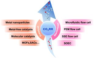

image file: d2ta02086f-p1.tif

Geng Li

Geng Li is currently a graduate student in Chemistry, City University of Hong Kong. He obtained his bachelor's and master's degrees from Nanjing University of Science and Technology in 2018 and University of Science and Technology of China in 2021, respectively. His current research interest is focused on the carbon dioxide electroreduction reaction mechanism and device design.

image file: d2ta02086f-p2.tif

Ruquan Ye

Ruquan Ye is an assistant professor in Chemistry, City University of Hong Kong. He received his B.S. (Chemistry) in 2012 from Hong Kong University of Science and Technology under Prof. Ben Zhong Tang's supervision, and his PhD (Chemistry) in 2017 from Rice University mentored by Prof. James M. Tour. He worked with Prof. Karthish Manthiram as a postdoctoral associate in Chemical Engineering at the Massachusetts Institute of Technology (2017–2018). His research interests include developing cost-effective methods for materials manufacturing and investigating their applications in energy and environmental science.


1. Introduction

The balance of the global carbon cycle has been disrupted by the overconsumption of fuels and increasing emissions of CO2, eventually resulting in a slew of ecological and environmental issues, such as global warming and the rise of sea levels.1,2 Limiting CO2 generation and turning it into valuable chemicals appear to be essential to mitigate the crisis. So far, several techniques have been developed to address the carbon emission problem, including CO2 capture,3,4 storage,5–7 and conversion.8–11 The electrochemical CO2 reduction reaction (CO2RR), coupled with renewable energy sources such as wind and solar energy, has been recognized as one of the optimum approaches to achieve carbon neutrality (Fig. 1).12,13 The utilization of photovoltaic and wind power in electrochemical CO2RR systems can simultaneously reduce the atmospheric CO2 concentration and convert the intermittent and unstable electricity into chemical fuels. Furthermore, as the cost of power generated by photovoltaic systems and wind turbines continues to drop, the electrochemical CO2RR is emerging as an attractive and sustainable technique for converting atmospheric CO2 into fuels and chemicals.
image file: d2ta02086f-f1.tif
Fig. 1 A schematic diagram of the electrochemical CO2RR to chemical fuels from renewable energy sources.

The electrocatalytic CO2RR is a complicated process that involves multiproton-coupled electron transfer and produces mixtures of reduction products. Based on the number of carbon atoms, CO2RR products are classified into C1 products including formate/formic acid (HCOOH), carbon monoxide (CO), methanol (CH3OH) and methane (CH4), C2 products including ethylene (C2H4), ethanol (C2H5OH) and acetate (CH3COOH), C3 products such as propylene (C3H6) and n-propanal (C2H5CHO), and long-chain products. However, there exists an intractable problem that CO2 is thermodynamically stable, leading to a large energy barrier for electrochemical CO2 activation.14 The electrochemical CO2RR is generally started by transferring a single electron to a linear CO2 molecule to generate bent CO2˙, which requires a potential of −1.9 V vs. the standard hydrogen electrode (SHE) (eqn (1)), indicating high activation energy for the CO2RR.15 Despite the close potential for different products (eqn (2)–(7)), the electrochemical CO2RR to hydrocarbons or oxygenates generally possesses a higher kinetic barrier than that of CO and HCOOH, since more electrons are required to form hydrocarbons or oxygenates.16 Furthermore, the hydrogen evolution reaction (eqn (8)) will compete with the CO2RR at the cathode, making it challenging to generate target products. Thus, designing and manufacturing CO2RR electrocatalysts with high activity and faradaic efficiency (FE) for a particular product are critical for industrial applications. Novel high-efficiency catalysts including metal-free catalysts, metal nanoparticles, and molecular catalysts and their derivatives have been developed for the electrochemical CO2RR in the last few decades.

 
CO2 + e → CO2˙, E0 = −1.90 V(1)
 
CO2 + 2H+ + 2e → CO + H2O, E0 = −0.53 V(2)
 
CO2 + 2H+ + 2e → HCOOH, E0 = −0.61 V(3)
 
CO2 + 6H+ + 6e → CH3OH + H2O, E0 = −0.38 V(4)
 
CO2 + 8H+ + 8e → CH4 + 2H2O, E0 = −0.24 V(5)
 
2CO2 + 12H+ + 12e → C2H4 + 4H2O, E0 = −0.34 V(6)
 
2CO2 + 12H+ + 12e → C2H5OH + 3H2O, E0 = −0.33 V(7)
 
2H+ + 2e → H2, E0 = −0.42 V(8)

Besides, the CO2RR is mostly investigated using the typical H-type electrolytic cell in the laboratory. The current densities for the CO2RR in this system are usually less than 50 mA cm−2 due to the low CO2 solubility in aqueous solution (∼0.03 mg kg−1 at ∼300 K, 1 atm in water), whereas the industrial-scale current densities should be at least 200 mA cm−2.17,18 Recently, efforts in building direct gas-feed reactors have provided the possibility for electrocatalytic CO2 conversion at industrial-scale current densities, presenting new insight on the technology's commercialization.19 In this review, we first summarize the literature on representative electrocatalysts in refining the selectivity of different products, and then discuss the latest progress in electrolytic cells for industrial-scale CO2RR. We also outline the challenges and prospects of this burgeoning research field.

2. CO2RR catalysts for different products

The electroreduction process begins with the adsorption and activation of CO2 on the surface of the catalyst, leading to the formation of *OHCO or *COOH intermediates (the atom with * binds to the surface) (Fig. 2). Then the *OHCO is further reduced to generate formic acid, while *COOH is reduced to *CO adsorbed on the catalyst surface. *CO will be easily desorbed as a gas product on the surface of catalysts with weak binding energies for *CO. Meanwhile, *CO can be further reduced to generate multi-electron products if it binds to the catalyst surface strongly. Considering the diversity of products, it is challenging to develop catalysts with high activity and selectivity. There are two main paths for further reduction of CO. The first one includes a succession of proton-coupled electron transfers that result in CH3OH and CH4 production. The second route begins with the dimerization of *CO to form *CO dimers followed by the hydrogenation process to generate C2+ products such as C2H4 and C2H5OH.20,21
image file: d2ta02086f-f2.tif
Fig. 2 Different pathways for the electrochemical CO2RR.

So far, metal catalysts have been the most effective catalysts for the CO2RR. Noble metals such as Au, Ag, and Pd, and non-noble metals like Zn show high catalytic activity towards CO2-to-CO electroreduction, because of their weak binding energies for *CO.22 p-Block metals, such as Sn, In, Bi, and Pd, and their composites, present a high selectivity for HCOO/HCOOH because of their favorable binding to *OHCO.23 Cu is usually used for multi-electron transfer products (such as CH4 and CH3OH) and C2+ products because of its moderate binding energy of *CO, which is a crucial intermediate product involved in the C–C dimerization step.24 However, bulk metals usually show low catalytic performance. In order to enhance the catalytic activity of metals, nanostructured metals with well-controlled morphologies and structures have been prepared for enhanced catalytic performances. In addition, metal alloying, which changes the adsorption to the intermediate, is another strategy to prepare highly active catalysts. More recently, single-atom catalysts (SACs) have also attracted increasing attention for the electrochemical CO2RR, because of their maximized atomic usage and tunable activities.25 Moreover, molecular catalysts and metal-free catalysts have also been developed to hinder the use of metals and decrease the preparation cost of catalysts. In this section, we will review representative electrocatalysts in refining the selectivity of different products.

2.1 Carbon monoxide

Among all the CO2RR products, CO has been considered the most commercially viable product because of its kinetically accessible process (two-proton and two-electron reaction) and high efficiency. Moreover, CO is an essential and indispensable precursor for producing various commodity chemicals in industry. For example, synthesis gas with a 2[thin space (1/6-em)]:[thin space (1/6-em)]1 CO/H2 ratio can be utilized to produce a variety of organic chemicals (such as higher hydrocarbons) via the Fischer–Tropsch process.24,26

So far, noble metals such as Au, Ag, and Pd, and non-noble metals like Zn have shown high catalytic activity towards CO2-to-CO electroreduction. Ag is the representative metal catalyst that has been most extensively explored for CO generation due to its high activity. Generally, Ag nanoparticles show higher catalytic performance than bulk Ag.27 Hwang et al.28 reported a series of differently sized Ag nanoparticles anchored on a carbon support via a one-pot synthesis method. The results showed that 5 nm Ag nanoparticles presented 4-fold improved FECO compared to the Ag foil at −0.75 V vs. the reversible hydrogen electrode (RHE). Density functional theory (DFT) calculations revealed that the high FE and current density were attributed to the specific interaction between Ag nanoparticles and the surface modification by the anchoring agent, which provided more active sites for the CO2RR. In addition, Ag catalysts with well-designed morphologies can also improve the catalytic activity for CO selection.29,30 Voiry et al.30 prepared a superstructural Ag catalyst via assembling two-dimensional Ag nanoprisms. The vertically stacked Ag nanoprisms exposed more than 95% of the edge sites, leading to an increased activity for CO2-to-CO electroreduction and exhibiting a high CO FE of 96.3% at −0.6 V vs. RHE (Table 1). Sun et al.31 synthesized 3D porous Ag nanostructures via in situ electroreduction of Ag benzenethiolate nanoboxes. The as-prepared porous Ag nanostructures exhibited high catalytic performance because of the abundant active sites, which resulted from the 3D hierarchical channels in the porous structures. The crystal facets of Ag also have a crucial impact on the activity and selectivity for the CO2RR. Generally, Ag(110) shows higher catalytic activity for CO2-to-CO conversion than Ag(111) or Ag(100).32,33 The DFT simulations revealed that the initial proton-coupled electron transfer for *COOH on the Ag(110) facet possessed a lower activation energy barrier than that on Ag(111) or Ag(100), leading to enhanced CO2RR performance.34

Table 1 Representative catalysts for electroreduction of CO2 to CO
Catalyst Catalyst type Potential (V vs. RHE) Partial current density (mA cm−2) Electrolyte FE (%) Ref.
Tri-Ag-NPs Ag-based nanoparticles −0.86 ∼1 0.1 M KHCO3 96.8 29
2D Ag-NPs Ag-based nanoparticles −0.6 3.89 0.1 M KOH 96.3 30
3D porous Ag Ag-based nanoparticles −1.03 6 0.1 M KHCO3 96 31
PON-Ag Ag-based nanoparticles −0.69 4.4 0.5 M KHCO3 96.7 33
CoPc/CNT-MD Molecular catalyst −0.9 ∼35 0.5 M KHCO3 97 37
CoPc/CB Molecular catalyst −0.68 18.1 0.5 M KHCO3 93 38
CoPP@CNT Molecular catalyst −0.6 25.1 0.5 M KHCO3 98.3 43
CoTMAPc@CNT Molecular catalyst −0.72 ∼20 0.5 M KHCO3 99 45
Ni-SAC@NCs SAC −0.6 ∼10 0.5 M KHCO3 95 50
FeN5 SAC −0.46 2 0.1 M KHCO3 97 51
Zn–N4 SAC −0.43 4.8 0.5 M KHCO3 95 54
Co–Tpy–C SAC −0.8 6 0.5 M NaClO4 98 55


Molecular catalysts have also been evaluated as CO2-to-CO catalysts because of their unique adjustable structures toward improved performance.35 Porphyrins and phthalocyanines are the most studied catalysts and have been widely used for the electrochemical CO2RR. Berlinguette et al.36 used a commercially available cobalt phthalocyanine (CoPc) as the electrocatalyst in a zero-gap membrane flow cell for the electrochemical CO2RR. A high selectivity of CO (>95%) could be achieved at a current density of 150 mA cm−2 with continuous long-term (more than 100 hours) operation, demonstrating molecular catalysts to be promising candidates for industrial CO2-to-CO conversion. However, molecular catalysts tend to suffer from poor electroconductivity and stability issues. Immobilizing molecular catalysts on carbonaceous supports such as carbon nanotubes (CNTs),37 carbon black (CB),38 and carbon paper (CP)39 can be an effective method to improve the current density and stability. The supports with high surface area, high conductivity, and catalytic inertness are conducive, as otherwise, they could interfere with the CO2RR.40–42 Zhao et al.37 dispersed CoPc on CNTs via π–π stacking interactions, achieving an FECO of 97% at 200 mA cm−2. In addition, the molecularly dispersed CoPc on CNTs presented higher catalytic activity and stability than the aggregated one.37 Covalent grafting is another effective method for the immobilization of molecular catalysts. For example, Han et al.43 covalently grafted cobalt porphyrin (CoPP) onto the surface of CNTs by reacting protoporphyrin IX cobalt chloride with hydroxyl-functionalized CNTs. This method enabled high catalyst loading in a better dispersion, achieving a high FECO of 98.3% at −0.65 V vs. RHE. Compared to non-covalent bonding, the covalent grafting method is more practical in stabilizing ionic molecular catalysts. For example, molecules with positively charged groups have shown higher CO2RR activity than those with the neutral counterparts.38,44 However, the presence of multiple ionic groups in the molecular catalysts may lead to poor stability because of the increased water solubility. To address this issue, Ye et al.45 covalently grafted a molecular catalyst onto CNTs via an in situ functionalization strategy to improve the stability. Cobalt tetraamino phthalocyanine (CoTAPc) was firstly covalently grafted on CNTs via a diazo-reaction, and then methylated to form cobalt tetra-(4-N,N,N-trimethylanilinium)phthalocyanine (CoTMAPc). A stable current density of 239 mA cm−2 and high FECO of 95.6% were obtained in a flow cell at −0.7 V vs. RHE.45 Another strategy to stabilize molecular catalysts is by forming a layered structure such as an ultrathin metal–organic framework or covalent organic framework, in which the metal complexes will be arranged in a co-planar configuration to avoid aggregation.46 In addition, fixing the metal complexes in the framework can also mitigate the leaching of catalysts.47

Single-atom catalysts (SACs) have attracted increasing attention for the electrochemical CO2RR, because of their high atom utilization efficiency and tunable activities. Metal centers are important factors for the catalytic performance of SACs. Generally, Ni and Fe-based SACs are highly active for CO production.48,49 Jiang et al.48 prepared a series of single-atom metals implanted in N-doped carbon (M–N–C; M = Fe, Co, Ni, and Cu) for CO2-to-CO conversion. The results showed that Ni–N–C and Fe–N–C had much lower energy barriers for *COOH formation than Co–N–C and Cu–N–C (Fig. 3a), indicating higher catalytic activity of Ni and Fe SACs. In addition, the limiting potential difference between the CO2RR and hydrogen evolution reaction (UL(CO2) − UL(H2)) was also evaluated for CO selectivity, and Ni–N–C showed a more positive value (Fig. 3b), representing higher CO2RR selectivity than hydrogen evolution. Zhou et al.50 recently prepared N-doped carbon-supported Ni SACs (Ni-SAC@NCs) as electrocatalysts for CO2-to-CO conversion. The as-prepared Ni-SAC@NCs could achieve a high FECO of 95% at −0.6 V vs. RHE and keep over 80% FE in a wide potential window (−0.6 to −0.9 V vs. RHE). Wang et al.51 synthesized singly dispersed FeN5 active sites supported on N-doped graphene with an additional axial ligand coordinated to FeN4via thermal pyrolysis of hemin and melamine molecules on graphene (Fig. 3c). The FeN5 SAC exhibited a high FECO of 97% at −0.46 V vs. RHE (Fig. 3d). DFT calculations showed that the weak binding strength of *CO to the FeN5 site promoted the desorption of CO, thus resulting in higher CO selectivity than in the case of FeN4 (Fig. 3e).51 In addition, Ni-based SACs usually present higher catalytic activity and improved partial current density compared to Fe-based ones, as the Fe–Nx site possessed strong binding of *CO.52 Zn- and Co-based SACs have a higher activation barrier for CO2-to-CO electrolysis and show poorer activity than the Ni and Fe-based SACs.22,53 Xu et al.54 prepared a N-anchored Zn SAC supported on carbon (ZnNx/C) for CO formation. The as-prepared ZnNx/C electrocatalyst showed a high catalytic selectivity with an FECO of 95% at −0.43 V vs. RHE. DFT calculations demonstrated that the four-N-anchored Zn active sites (Zn–N4) could reduce the energy barrier for the formation of *COOH, leading to high catalytic activity for CO selection. Kang et al.55 synthesized a series of Co SACs (Co–Tpy–C) by pyrolysis of a Co terpyridine organometallic complex at different temperatures. The Co–Tpy–C electrocatalyst showed excellent catalytic performance for CO formation with over 95% FE in a wide potential window (−0.7 to −1.0 V vs. RHE). Regulating the coordination environment of SACs can be an effective approach to improve the CO2-to-CO electroreduction performance.56–58 For example, Co SACs with different nitrogen coordination numbers showed different catalytic performance for the CO2RR towards CO production.56 A Co SAC with two coordinated nitrogens (Co–N2) presented higher catalytic activity than the Co SAC with four coordinated nitrogens (Co–N4), achieving FECO of 94% at −0.63 V vs. RHE with a current density of 18.1 mA cm−2 (Fig. 3f–h). The reduced nitrogen coordination number led to extra vacant 3d orbitals of Co atoms that might be beneficial for CO2 reduction.


image file: d2ta02086f-f3.tif
Fig. 3 (a) Free energy diagrams of CO2 reduction to CO on M–N–C; M = Fe, Co, Ni, and Cu. (b) The values of UL(CO2) − UL(H2) for M–N–C. Adapted with permission.48 Copyright 2020, Wiley-VCH. (c) Synthetic route towards single-atom FeN4 and FeN5 catalysts. (d) FECO of FeN4 and FeN5 catalysts at different potentials. (e) Free energy profile with the optimized intermediates of CO2 reduction to CO on FeN4 and FeN5 catalysts. Adapted with permission.51 Copyright 2019, Wiley-VCH. (f) LSV of Co–N2, Co–N3, Co–N4, and Co NPs and pure carbon. (g) CO FEs at different applied potentials of Co–N2, Co–N3, and Co NPs. (h) Gibbs free energy diagrams of electroreduction to CO on Co–N2 and Co–N4. Adapted with permission.56 Copyright 2018, Wiley-VCH.

2.2 Formate/formic acid

Formate/formic acid (HCOO/HCOOH) is a valuable chemical ingredient employed in various industries, and its consumption has expanded significantly over the last several years.59 p-Block metals, such as Sn, In, Bi, and Pd, and their composites, present a high selectivity for HCOO/HCOOH.23 Sn is among the most widely employed metals for HCOOH electrocatalysis. Jaramillo et al.60 presented a volcano plot (Fig. 4a) for HCOO partial current density using *OCHO binding energy as a descriptor. Sn was at the saddle point of the volcano curve, indicating the optimal lowest *OCHO binding energy of Sn and thus the highest HCOOH selectivity.60 Both Sn metal and Sn oxides display remarkable catalytic activity for CO2-to-HCOOH conversion. SnIV, in particular, can efficiently minimize the CO2 reduction overpotential by reducing the energy barriers of HCOOH formation. Meanwhile, SnII helps to increase selectivity toward HCOOH production by increasing the energy barriers for H2 and CO generation according to the DFT calculations.61 Multivalent Sn species exhibit higher catalytic activity than Sn or Sn oxides. Kang et al.62in situ constructed SnO2/Sn heterostructures on the surface of SnO2 nanoparticles, which exhibit higher FEHCOOH of 93% at −1.0 V vs. RHE (Table 2) than pristine SnO2 and Sn. A series of Sn/SnO/SnO2 nanosheets were also reported, exhibiting a high FEHCOOH of 89.6% at −0.9 V vs. RHE.63 Theoretical simulations demonstrated that multivalent Sn species synergistically accelerated CO2 activation, *OCHO adsorption, and electron transfer, resulting in a higher reduction rate of Sn/SnO/SnO2.63 Moreover, the morphologies and structures of SnOx also influence the reduction activity.64–66 A wavy structural SnO2 network (Fig. 4b) showed a higher catalytic performance than commercial SnO2 nanoparticles, with FEHCOOH of 87.4% and current density of 22 mA cm−2 at an applied potential of −1.0 V vs. RHE.65 Ultrathin SnO2 quantum wires also exhibited enhanced current density and improved FE compared to SnO2 nanoparticles because of the abundant grain boundaries as active sites on the surface.64
image file: d2ta02086f-f4.tif
Fig. 4 (a) Volcano plot using *OCHO binding energy as a descriptor for HCOO partial current density at −0.9 V vs. RHE. Adapted with permission.60 Copyright 2017, the American Chemical Society. (b) Synthetic process towards NW-SnO2. Adapted with permission.65 Copyright 2020, Elsevier. (c) Volcano plots of j0 as a function of the ΔGH* for Bi and other catalysts. (d) Gibbs free energy diagrams of Bi for the reduction of CO2 into HCOOH. (e) Gibbs free energy diagrams of Bi for the reduction of CO2 into CO. Adapted with permission.67 Copyright 2020, Wiley-VCH. (f) TEM image of Bi NSs. (g) Gibbs free energy profiles for CO2 electroreduction to HCOOH on Bi NPs and Bi NSs. (h) FEs and CEEs of formic acid over two electrocatalysts in 1 M KOH. Adapted with permission.68 Copyright 2020, Wiley-VCH.
Table 2 Representative catalysts for electroreduction of CO2 to HCOOH
Catalyst Catalyst type Potential (V vs. RHE) Partial current density (mA cm−2) Electrolyte FE (%) Ref.
Sn foil Metal Sn −0.9 0.1 M KHCO3 70 60
SnO2/Sn Sn oxides −1.0 28.7 0.5 M KHCO3 93 62
Sn/SnO/SnO2 Sn oxides −0.9 ∼20 0.5 M KHCO3 89.6 63
Sub-2 nm SnO2 QWs Sn-based nanoparticles −8.2 ∼11 0.1 M KHCO3 87.3 64
NW-SnO2 Sn-based nanoparticles −1.0 22 0.5 M KHCO3 87.4 65
DEA–SnOx/C Sn-based nanoparticles −7.5 6.7 0.5 M KHCO3 84.2 66
Bi/rGO Metal Bi −0.8 0.1 M KHCO3 98 67
Bi NTs Bi-based nanoparticles −1.0 ∼30 0.5 M KHCO3 97 69
Bi2O3NSs@MCCM Bi oxides −1.26 17.7 0.1 M KHCO3 93.8 71
Bi2O3-NGQDs Bi oxides −1.0 22 0.5 M KHCO3 95 72
Bi–Sn aerogel Bimetal −1.0 10 0.1 M KHCO3 93.9 73
Bi–SnO/Cu foam Bimetal −1.7 vs. Ag/AgCl 12 0.1 M KHCO3 93 74
In1.5Cu0.5 NPs Bimetal −1.2 8 0.1 M KHCO3 90 77
Zn0.95In0.05 Bimetal −1.2 22 0.5 M KHCO3 95 78


Bi also presents good HCOO/HCOOH production selectivity and high catalytic stability for CO2 electrocatalytic reduction. Jiang et al.67 demonstrated a volcano plot of j0 as a function of the ΔGH* for Bi and other catalysts (Fig. 4c). Bi appeared at the bottom corner point of the volcano plot, which indicated the poor HER performance of Bi and the possibility for high CO2RR activity.67 The free energy calculations (Fig. 4d and e) revealed that HCOOH generation was more favorable than CO generation, attributed to the lower ΔGRDS.67 Furthermore, Bi catalysts with varying surface structures exhibit different catalytic capabilities. A series of Bi nanosheets with flat surfaces (Bi NSs) and Bi nanotubes with surface curvatures (Bi NTs) were manufactured to investigate the electrochemical CO2-to-HCOOH performance.69 Bi NTs acquired a maximum FEHCOOH of 97% at −1.0 V vs. RHE and a wide potential window of over 80% FE, which was superior to that of Bi NSs and Bi bulk powder.69 DFT simulations revealed that the higher *CO2 absorption near the curved Bi NT surfaces minimized the energy barrier for CO2 reduction to HCOOH.69 Wu et al.68 constructed leafy structural Bi NSs (Fig. 4f) by in situ electroreduction of the Bi-based metal–organic framework CAU-17. The leafy structure with abundant Bi/Bi–O active sites reduced the free energy barrier for *CO2 to *OCHO from 0.46 eV to 0.17 eV (Fig. 4g), resulting in remarkable HCOOH formation performance (>200 mA cm−2, >90% FE, Fig. 4h).68 Bi oxides also exhibit excellent catalytic performance towards HCOOH formation.70–72 For example, immobilizing Bi2O3 nanosheets on a multi-channel carbon matrix (Bi2O3NSs@MCCM) could afford a maximum FE of 93.8% at −1.26 V vs. RHE with a corresponding current density of 17.7 mA cm−2.71 The interwoven MCCM with faster electron transport and the ultrathin Bi2O3 nanosheets with ample active sites simultaneously enabled high FE (>90%) to be obtained in a broad potential window.71

Constructing bimetallic electrocatalysts is also an effective strategy for improving the HCOOH electrosynthesis. A three-dimensional porous Bi–Sn bimetallic aerogel exhibited superior catalytic performance to Bi and Sn, with a high FEHCOOH of 93.9% at −1.0 V vs. RHE.73 The as-prepared aerogel established more active sites because of the interconnected channels and abundant interfaces.73 DFT calculations demonstrated that the coexistence of Bi and Sn lowered the energy barrier for the synthesis of HCOOH, resulting in improved catalytic activity.73 Guan et al.74 used Cu foam as the substrate to grow Bi-doped SnO nanosheets, forming a Bi–SnO/Cu foam electrode. Bi doping strengthened the selectivity of HCOOH by enhancing the adsorption capacity of the SnO(001) facet for *OCHO intermediates via electron orbital hybridization.74 Furthermore, electrons were transferred from the electrocatalyst to the Cu foam, which favored the adsorption of *OCHO intermediates by maintaining Sn in a positive oxidation state.74 A series of Bi/CeOx catalysts were prepared, exhibiting high production rate (2600 μmol h−1 cm−2) and FE (92%) at high current density (149 mA cm−2).75 The enhanced performance of Bi/CeOx was attributed to its larger electrochemically active surface area (ECSA), plentiful catalytically active sites, facilitated CO2 adsorption and activation, faster charge transfer, and reaction intermediate stability by the supporting amorphous CeOx matrix.75 Heterostructured intermetallic CuSn electrocatalysts (Cu3Sn/Cu6Sn5) supported on porous copper foam demonstrated an FE of 82% and a current density of 18.9 mA cm−2 at −1.0 V vs. RHE.76 Theoretical calculations revealed that the high catalytic activity was primarily due to the interfaces between the Cu6Sn5 and Cu3Sn intermetallics, where the adsorption of the *OCHO intermediate was stronger than that of *COOH. The free energy of adsorbed hydrogen was also upshifted, leading to the suppression of the HER and the selective production of HCOOH.76 Bimetallic InxCuy (x and y are the molar ratio) nanoparticle (NP) electrocatalysts, with different growth directions of crystal facets with varying In/Cu ratios, realized 90% FE at −1.2 V vs. RHE.77 DFT calculations further revealed that the In(101) facet of InxCuy NPs stabilized the *OCHO intermediate more effectively, thereby reducing the potential barrier for CO2 to HCOOH conversion.77 In–Zn bimetallic nanocrystals outperformed In NCs because of the In–Zn interfacial sites, with a high FE of 95% and a formation rate of 0.40 mmol h−1 cm−2 at −1.2 V vs. RHE.78

2.3 Methane

Electroreduction of CO2 to CH4 is more economically advantageous, considering that CH4 has the highest gravimetric energy density (13.9 kW h kg−1) among all the hydrocarbon compounds and has been utilized as an alternative energy carrier to replace traditional fossil fuels.79 However, the electroreduction process is more difficult because of the eight-electron step, which requires a higher overpotential.

Cu-based heterogeneous catalysts have attracted considerable attention due to their propensity to produce multi-electron transfer products. They are considered one of the most promising candidates for electroreduction of CO2 to CH4. For example, by employing electrodeposited Cu on carbon paper, Zhang et al.80 achieved an FE for CH4 formation of 85% with a partial current density of 38 mA cm−2 at −2.8 V vs. RHE (Table 3). Besides, the facet, size, and morphology of nanostructured Cu also influence the generation of the target products. It has been revealed that the Cu(111) surface is selective for CH4, whereas the Cu(100) facet enhances C2H4 generation at low overpotentials.81,82 A series of Cu spheres (Cusph), Cu cubes (Cucub) and Cu octahedra (Cuoh) were synthesized according to colloidal methods.83 The Cucub with the (100) facet was highly selective toward C2H4, while Cuoh with the (111) facet preferred the production of CH4. Buonsanti et al.84 prepared different sized octahedral Cu(111) nanocrystals varying from 75 to 310 nm (Fig. 5a–c). The 75 nm Cu(111) octahedral nanocrystals showed the best performance with 55% FE for CH4 at −1.25 V vs. RHE (Fig. 5d). Moreover, forming a core–shell structure with surface coating on Cu can further improve the selectivity towards CH4 and stabilize the morphology during catalysis.85,86 For example, Cu nanowire electrodes coated with polydopamine (PDA) showed 2.3 times higher CH4 selectivity and catalytic stability, compared with the pristine Cu nanowires (Fig. 5e–h).86 The amino groups of PDA facilitated the proton transfer from the bulk solution to the catalytic interface and the phenol hydroxyl tended to stabilize the *CO intermediates, promoting the formation of CH4 on the Cu nanowire surface.

Table 3 Representative catalysts for electroreduction of CO2 to CH4
Catalyst Catalyst type Potential (V vs. RHE) Partial current density (mA cm−2) Electrolyte FE (100%) Ref.
Cu–P-ED Cu-based catalyst −2.8 38 0.5 M NaHCO3 81 80
Octahedral CuNCs Cu-based catalyst −1.25 0.1 M KHCO3 55 84
Ultrathin CuNWs Cu-based catalyst −1.25 ∼8 0.1 M KHCO3 55 85
CuNWs@PDA Cu-based catalyst −0.93 0.5 M KHCO3 29 86
Cu3Pd Bimetal −1.2 ∼4 0.1 M KHCO3 40.6 87
Cu/ZnOx Bimetal −1.1 ∼17 0.1 M KHCO3 ∼36 88
CuAg Bimetal −1.17 0.1 M KHCO3 72 89
CuAg thin film Bimetal −1.4 0.1 M KHCO3 59.3 90
AgCo Bimetal −2 0.5 M KHCO3 19.5 91
Cu–N–C-900 SAC −1.6 14.8 0.1 M KHCO3 38.6 92
CuN2O2 SAC −1.44 ∼30 0.5 M KHCO3 78 93
Fe–N–C SAC SAC −1.8 31.8 1 M KHCO3 85 96
Cu-3TPyP SAC −1.0 1 M KOH 62.4 103
g-C3N4 Metal-free catalyst −1.27 14.8 0.5 M KHCO3 44 99
EDTA@CNT Metal-free catalyst −1.3 16.5 0.5 M KHCO3 61.6 102


image file: d2ta02086f-f5.tif
Fig. 5 (a–c) TEM images of the 75 nm, 150 nm, and 310 nm Cuoh-NCs. Scale bars are 300 nm. (d) FEs of the three sizes of Cuoh-NCs with a loading of 11 mg cm−2 on glassy carbon plates measured in CO2-saturated 0.1 M KHCO3 at different potentials. Adapted with permission.84 Copyright 2020, American Chemical Society. (e) The FEs for Cu nanowires at the initial and final stages of electrocatalysis. (f) TEM images of Cu nanowires before and after 1 h electroreduction. (g) The FEs for Cu nanowires@PDA at the initial and final stages of electrocatalysis. (h) TEM images of Cu nanowires@PDA before and after 1 h electroreduction. Adapted with permission.86 Copyright 2018, Wiley-VCH.

Alloying Cu with a second metal is another widely adopted way to improve CH4 selectivity. A series of PdCu bimetallic catalysts with different structures were synthesized by adjusting the composition ratio.87 In particular, the concave rhombic dodecahedral Cu3Pd nanocrystals exhibited FE of 40% toward CH4 at −1.2 V vs. RHE with enhanced CH4 current density compared to Cu foil, resulting from the high-index facets and alloying effect. Cu/ZnOx nanoparticles, constructed by magnetron sputtering and subsequent oxidation–reduction treatment, exhibited a maximum FE of ∼36% at −1.1 V vs. RHE and a long-term durability for electroreduction to CH4 due to the active sites at the Cu/ZnOx interface.88 Huang et al.89 established an intimate atomic CuAg interface on the surface of Cu nanowires, achieving a maximum FE of 72% towards CH4 generation at −1.17 V vs. RHE. Recently, an oxidation-resistive CuAg thin film was reported, which electroreduced preferentially to CH4 (FE of 59.3%) at −1.4 V vs. RHE.90 Despite the majority of the alloys for CH4 production being Cu-based, some alloys without Cu were also reported. For example, Verma et al.91 prepared a bimetallic AgCo electrocatalyst by simultaneously reducing Co(NO3)2 and AgNO3 with sodium borohydride. The maximum FE observed for CH4 was 19.5% at −2.0 V vs. RHE.

SACs have also been evaluated as heterogeneous catalysts for electrochemical CH4 selection because of their unique electrical characteristics and maximized atomic usage. A series of single-atom Cu catalysts distributed on nitrogen-doped carbon were prepared by changing the pyrolysis temperature and the N coordination conditions. The highest CH4 FE was 38.6% at −1.6 V vs. RHE with a partial current density of 14.8 mA cm−2.92 DFT simulations further indicated that high Cu concentration with nearby Cu–N2 sites was more favorable for the C2H4 generation owing to the reduced free energy for C–C coupling, whereas the isolated Cu–N4, the neighboring Cu–N4, and the isolated Cu–N2 were all prone to yield CH4.92 A carbon-dots-based CuN2O2 SAC was synthesized with remarkably high FE (78%) and high partial current density of 40 mA cm−2.93 The introduction of oxygen ligands provided a new electronic structure, leading to lower required energy for the limiting step to form CH4.93 Ultrathin porous Al2O3 with enriched Lewis acid sites was explored as an anchor for Cu single atoms to catalyze electrochemical CO2 methanation, showing the FE for CH4 approaching 62% at −1.2 V vs. RHE with the corresponding current density of 94.8 mA cm−2.94 Theoretical calculations suggested that Lewis acid sites in metal oxides could promote CO2 methanation by optimizing intermediate adsorption. In addition, non-Cu-based SACs for CH4 production have also been investigated.95,96 For example, Zn SACs dispersed onto microporous N-doped carbon exhibited a high CH4 FE of 85% at −1.8 V vs. SCE with a corresponding partial current density of 31.8 mA cm−2.96 Theoretical calculations revealed that for Zn SACs, the O atom rather than the C atom in the *OCHO intermediate preferred to form a chemical bond with Zn, blocking the generation of CO and helping to produce CH4. Moreover, inspired by the bimetallic alloy catalysts, dual-atom catalysts (DACs), such as CuCr/C2N97 and N6V4–AgCr,98 have been investigated for electrochemical reduction toward CH4. They showed an extremely low overpotential due to the multiple active centers.

Metal-free catalysts, such as graphitic C3N4 (g-C3N4),99 borophene,100 graphene quantum dots (GQDs),101 and ethylenediaminetetraacetic acid (EDTA),102 have also been studied for electroreduction of CO2 to CH4. For example, Chen et al. reported that EDTA immobilized on CNTs showed a high FE of 61.6% toward CH4 at −1.3 V vs. RHE with a partial current density of 16.5 mA cm−2, competing with state-of-the-art Cu-based catalysts. The Lewis basic COO groups in the EDTA molecule were suggested to be the active sites for CO2 reduction.

2.4 Methanol

Methanol is an important commodity chemical in industry. It can be used as clean fuel directly due to its high energy density and stable storage properties. Besides, CH3OH can also be used as a feedstock to produce liquid fuels such as dimethyl ether (DME), synthetic gasoline, and several organic compounds.104 Currently, most of the commercial CH3OH is produced from syngas (the mixture of CO and H2) under high temperature (250–300 °C) and pressure (3.5–10 MPa), which usually requires high-security equipment.105 Electrochemical reduction of CO2 to CH3OH provides a new platform to produce CH3OH under ambient conditions.

Compared with CO and HCOOH, the transformation of CO2 to CH3OH requires six electrons, so the reduction reaction is considered kinetically slow. Among the studied materials, Cu and Pd, as well as their mixtures and oxidized forms, have been reported to be the most active materials for the electrochemical transformation of CO2 to CH3OH.106,107 Flake et al.108 demonstrated that Cu2O electrodes showed a remarkably higher CH3OH yield rate (43 μmol cm−2 h−1) and FE (38%) than air-oxidized or anodized Cu electrodes (CuO) (Table 4), suggesting that CuI species play a critical role in electrode activity and selectivity to CH3OH. However, there are two shortcomings of the Cu2O catalyst: (1) the current density is not high; (2) Cu2O is not stable and it may be reduced to metallic Cu, resulting in the generation of side products. To solve these problems, many strategies have been proposed. For example, Cu2O loaded on CNTs could increase the current density.109 Supporting Cu2O on the CNTs increased the active surface area and the accessibility of the reactants to the active sites because of the high length-to-diameter tubular structure of CNTs. The presence of the CNTs offered both reaction sites and electrons to increase the conversion rate of the intermediates to targeted multi-electron products.109 In addition, mixing ZnO with Cu2O (Cu2O/ZnO) showed better stability (5 h) than pure Cu2O (0.5 h).110 It was proposed that ZnO strengthened the Cu–CO bond, increasing the selectivity to alcohols and stabilizing Cu in the hydrogenation reaction.110 Besides, Cu2O/ZnO-based gas-diffusion electrodes could solve the mass transfer problem and improve current density and stability.111 A series of CuSe nanocatalysts were prepared for electrochemical reduction of CO2 to CH3OH using 1-butyl-3-methylimidazolium tetrafluoroborate ([Bmim]BF4) aqueous solution as electrolyte.112 The as-prepared Cu1.63Se(1/3) nanocatalysts presented a high FE of 77.6% at a low overpotential of 285 mV with a current density of 41.5 mA cm−2. The usage of ionic liquid enhanced the mass transport of CO2 to the catalyst surface, accelerating the formation of crucial *CO species for CH3OH production (Fig. 6a). Constructing bimetallic catalysts can be an effective way to improve the catalytic performance for CO2-to-CH3OH conversion. For example, nanostructured CuAu alloys showed 19 times higher FE than that on pure Cu because of the multifunctional catalysis of the alloys.113 Han et al.114 prepared PdCu bimetallic aerogels via a template-free self-assembly process, achieving a high FE of 80% at a very low overpotential (0.24 V). The amorphous Cu had large numbers of abundant defects as catalytic centers to enhance the CO2RR. In addition, the Pd–Cu surface was beneficial for CO2 chemical adsorption and subsequent hydrogenation. So the synergistic effect between Pd and Cu as well as the network structure of the aerogels improved the performance of CO2-to-CH3OH conversion. Well-designed morphologies and structures can also enhance the catalytic activity. Zheng et al. prepared 2D hierarchical Pd/SnO2 nanosheets and achieved a high 54.8% at −0.24 V vs. RHE.107 This kind of structure could promote the adsorption of CO2 on Pd–O–Sn interfaces, leading to enhanced electrocatalytic selectivity and stability. Wang et al.115 designed a hollow urchin-like structure of Co(CO3)0.5(OH)·0.11H2O (Fig. 6b) and obtained a high FE of 97% for CH3OH selection. The hollow urchin-like structure enhanced the transfer of CO2 and diffusion of the generated CH3OH, promoting CO2 electroreduction activity.

Table 4 Representative catalysts for electroreduction of CO2 to CH3OH
Catalyst Catalyst type Potential (V vs. RHE) Partial current density (mA cm−2) Electrolyte FE (100%) Ref.
Cu2O Cu oxides −1.1 ∼5 0.5 M KHCO3 38 108
Cu2O/CNTs Cu oxides −0.8 12 0.5 M NaHCO3 38 109
Cu2O/ZnO Cu oxides −1.3 (vs. Ag/Ag+) 10 0.5 M KHCO3 25 110
Cu1.63Se(1/3) Bimetal −2.1 (vs. Ag/Ag+) 41.5 [Bmim]PF6/CH3CN/H2O (5 wt%) 77.6 112
Pd83Cu17 Bimetal −2.1 (vs. Ag/Ag+) 31.8 [Bmim]BF4/H2O 80 114
Pd/SnO2 Bimetal −0.24 54.8 0.1 M NaHCO3 54.8 107
Co(CO3)0.5(OH)·0.11H2O Morphology change −0.98 (vs. SCE) 0.1 M NaHCO3 97 115
CoPc/CNR Molecular catalyst −0.64 2.91 0.5 M KHCO3 14.3 116
CoTAPc/CNT Molecular catalyst −1.0 10 0.5 M KHCO3 28 117
Co-corrole Molecular catalyst −0.64 0.1 M phosphate 43 118


image file: d2ta02086f-f6.tif
Fig. 6 (a) Mechanism study of CO2 reduction to methanol in an ionic liquid. Adapted with permission.112 Copyright 2019, Springer Nature. (b) Schematic of the synthesis of hollow urchin-like Co(CO3)0.5(OH)·0.11H2O. Adapted with permission.115 Copyright 2018, The Royal Society of Chemistry.

Molecular catalysts are another class of catalysts that can produce CH3OH from CO2via the electrochemical method. Robert et al.116 deposited CoPc onto CNTs, and found that at pH 13, the CoPc could reduce CO to methanol with an FE of 14.3% at −0.64 V vs. RHE. The pH had a significant effect in producing methanol; both acidic and highly basic solutions of pH 4 and 14 produced less methanol. The methanol selectivity decreased after long-term electrolysis, which was speculated to be due to the reduction of the C[double bond, length as m-dash]N bond. In a similar study by Wang et al.,117 highly dispersed CoPc on commercial CNTs (CoPc/CNT) also tuned the selectivity from CO to methanol. The production of methanol was proposed to go through a similar but not identical pathway, in which CO2 was first reduced in a domino process to CO and further to methanol. Although the mechanism of the CNT induced effect was not clear, it was possible that the strong catalyst/CNT interaction played a critical role in tuning the electronic structure, as the dispersion of CoPc on other supports showed poor CO2-to-methanol activity. Roy et al.118 reported a cobalt(III) triphenylphosphine corrole complex (Co-corrole), which can reduce CO2 to methanol (FE of 43% at −0.64 V vs. RHE) in 0.1 M phosphate buffer. Schöfberger et al.119 also reported a similar structural Mn corrole complex (Mn-corrole), which can also electroreduce CO2 to CH3OH with a maximum FE of 19%. The corrole molecule seemed to make the radical intermediates more stable at the metal site, leading to the formation of multi-electron reduced products.118

2.5 C2+ products

Multicarbon (C2+) products are more attractive than C1 products due to their higher energy density as fuels and enhanced value as feedstocks in the chemical industry. So far, Cu and Cu-based compounds are the only metal materials explored to promote the CO2RR to C2+ products with significant yields. Cu exhibits moderate binding energy for *CO, a crucial intermediate product involved in the C–C dimerization step.120

Cu species with controllable sizes and facets have been widely investigated to improve the catalytic activity towards C2+ selection. As discussed in the Methane section (Section 2.3), the Cu(111) facet is selective for CH4. For other facets, Cu(100) enhances C2H4 generation and the Cu(110) facet favors C2 oxygenate products like CH3COOH, CH3CHO, and C2H5OH.121 A series of Cu2O nanocrystals with different crystal facets were prepared for the electrochemical reduction of CO2 to C2+ products.122 The as-obtained concave octahedral Cu2O with (511) high-index facets presented improved FE and increased current density for C2+ production compared to the dodecahedral Cu2O with the (110) facet and cubic Cu2O with the (100) facet, achieving the highest FE of 48.3% and partial current density of 17.7 mA cm−2 at −1.1 V vs. RHE. The well-maintained high-index facets and the active sites at the grain boundaries of the octahedral Cu2O catalyst improved the C–C coupling reaction efficiency during the CO2RR.122 Besides the facets, well-designed morphologies can also enhance the catalytic performance. Sun et al.123 reported Cu nanodendritic structures (Cu NDs) with a high ECSA (Fig. 7a). The abundant active sites facilitated electron transport and the C–C coupling reaction between *CO intermediates, leading to approximately 70–120% higher C2H4 generation than the the initial Cu particles (Fig. 7b). Yang et al.124 prepared mesoporous Cu nanoribbons via in situ electrochemical reduction of Cu-MOFs. The mesoporous structure of Cu nanoribbons could concentrate OH on the surface, which increased the local pH and led to improved selectivity of C2+ products.


image file: d2ta02086f-f7.tif
Fig. 7 (a) SEM images of Cu NDs at specific applied potentials after potentiostatic electrolysis for 20 min. (b) Faradaic efficiencies for the CO2RR of the Cu particles (left) and the Cu NDs (right). Adapted with permission.123 Copyright 2020, American Chemical Society. (c) Schematic diagram of the CO2RR occurring at the Cu/PANI interface. (d) FE for every product and ECSA-normalized current density for the Cu. (e) FE for every product and ECSA-normalized current density for the Cu/PANI. Adapted with permission.125 Copyright 2020, American Chemical Society.

The chemical state of Cu is another important parameter for the CO2RR to C2+ products. During the electroreduction process, the electrodes tend to be reduced to Cu0, regardless of the initial states. The peroxidation of Cu generally shows excellent selectivity toward C2+ products.126,127 Han et al.128 prepared two Cu-based electrodes with mixed oxidation states, HQ–Cu (containing Cu, Cu2O, and CuO) and AN–Cu (containing Cu and Cu(OH)2), to investigate the origin of the superior performance in oxide-/hydroxide-derived Cu. The results showed that the oxide crystals in HQ–Cu and the hydroxide crystals in AN–Cu were all reduced and fragmented into small irregular Cu grains, which facilitated C–C coupling at the grain boundaries. A similar oxide-formation and reduction process of Cu foils in aqueous solutions of KCl, KBr, or KI was also reported to show high catalytic performance due to the high density of surface defect sites at the prepared Cu surface after electroreduction.129 The coexistence of Cu+ and Cu0 species also shows better performance.130–132 However, the active Cu+ species were likely reduced under CO2RR conditions. Yu et al.133 prepared catalysts with a nanocavity confinement structure, stabilizing the Cu oxidation state. The as-designed Cu2O with nanocavities presented C2+ generation with an FE of over 75% and a partial current density of 267 mA cm−2.

Catalyst surface modification is another practical strategy to enhance the performance of the electrochemical CO2RR. This strategy can tailor the microenvironments near the catalyst surface for target products. Wang et al.134 modified Cu electrodes with a series of amino acids, including glycine, DL-alanine, DL-leucine, DL-tyrosine, DL-arginine, and DL-tryptophan. The results showed that Cu electrodes modified with all kinds of amino acids performed better in producing C2H4 than the bare Cu electrode.134 Theoretical calculations revealed that the hydrogen bond formation between CHO* and –NH2 stabilized the CHO*, resulting in the improved generation of C2+ products in the CO2 electroreduction.134 A Cu surface coated with polyaniline (PANI) film (Fig. 7c) demonstrated enhanced FE for C2+ hydrocarbons (60%) compared with pristine Cu (FE of 15%), as shown in Fig. 7d and e.125 The superiority of the Cu/PANI was attributed to the coverage of PANI on the Cu surface, which improved the adsorption of the *CO intermediate and thus facilitated the C–C coupling, as revealed by in situ infrared spectroscopy.125 Inspired by the construction of gas-trapping cuticles on subaquatic spiders, a superhydrophobic dendritic Cu coated with long-chain alkanethiols was proposed to mimic this kind of structure for the CO2RR.135 The bionic hydrophobic electrode obtained a high FE of 56% for C2H4 and 17% for C2H5OH under neutral conditions, superior to that of a wettable cathode (FE of 9% for C2H4 and 4% for C2H5OH). The superiority was attributed to the concentrated gaseous CO2 wrapped on the hydrophobic Cu surface, consequently improving CO2 reduction selectivity.135 Bell et al.136 adjusted the microenvironments of a bare Cu surface using different cation- and anion-exchanging ionomer-layer stacks. The commercial anion-exchanging ionomer Sustainion could improve the CO2 solubility because of the imidazolium groups with high CO2 affinity.137 The negatively charged Nafion resin was used as an anion exchanging ionomer, which led to the exclusion of anions (bicarbonates) and gathering of CO2RR-produced OH, forming a high pH condition around the Cu surface. The increased CO2 solubility and the increased local pH by the bilayers influenced the overall water concentration and the product selectivity.

Metal-free carbon-based catalysts have also been applied as electrocatalysts to convert CO2 to C2 products. Pure carbon materials are inactive for the CO2RR because of the weak CO2 adsorption ability and high energy barrier for CO2 activation.138 Incorporating heteroatoms (such as boron, nitrogen, and sulfur) into carbon composites is an effective way to increase CO2 activation capability, which lowers the energy barrier for C–C coupling on carbon-based materials.139 Ajayan et al.140 prepared N-doped graphene quantum dots (NGQDs) via in situ N doping on an exfoliated graphene oxide (GO) precursor. The NGQDs demonstrated a high FE of 90% for the overall CO2RR, with a major hydrocarbon product, C2H4 (a maximum FE of 31% at −0.75 V vs. RHE), and a major oxygenate component, C2H5OH (a maximum FE of 16% at −0.78 V vs. RHE).140 The high performance of NGQDs was obtained by the introduction of the N atom into sp2-bonded carbon frameworks and the unique nanostructure of doped zigzag edges, which offered active sites for adsorbing CO2.140,141 Yu et al.142 proposed a nitrogen-doped nanodiamond/Si rod array (NDD/Si RA) cathode for electroreduction of CO2, presenting a major product of CH3COOH (FE of 91% in a wide potential window from −0.8 to −1.0 V vs. RHE). The excellent efficiency could be attributed to its large energy barrier for the HER and the abundant, highly active N–sp3C species for the CO2RR.142 Furthermore, B- and N-co-doped nanodiamond (BND) was reported for improved selection of C2H5OH. The BND achieved a high C2H5OH FE of 93.2% at −1.0 V vs. RHE, attributed to the synergistic effect of B and N co-doping.143 Apart from heteroatom doping, tailoring porous carbon textures, which provides more active sites for CO2 capture and reduction, could be another promising way to improve the CO2 reduction performance. For example, N-doped mesoporous carbon with ordered cylindrical channel structures had high selectivity and efficiency towards C2H5OH.144,145 DFT simulations revealed that microporous structures with active N sites had fast charge transfer kinetics and large driving potentials, which were critical for enhancing C2H5OH production.145

In summary, catalysts have drawn the most intense research efforts in the last decade, resulting in fast advancements in CO2RR performance. The selectivity and catalytic performance of catalysts are not only related to their inherent properties, but also depend on their structures and morphologies. Reducing the bulk metal to nano-sized and even atom-sized catalysts (SACs) can be an effective method to get more active sites for the CO2RR. Constructing bimetallic catalysts can be another strategy to obtain highly active catalysts because of the synergistic effect. As for the molecular catalyst, in addition to the molecular structures, the immobilization and good dispersion on carbonaceous supports can improve the electrical conductivity and expose more active sites for the CO2RR. Moreover, the development of metal-free catalysts is important to reduce the catalyst cost in industrial utilization.

3. Electrolyzer design

Conventional H-cell configurations are suitable for laboratory-scale screening of catalysts for the electrochemical CO2RR. However, they are severely constrained by mass transport due to the low solubility of CO2 in aqueous electrolytes. With the development of flow cell configurations, vapor-fed CO2 electrolyzers provide a promising platform for the commercialization of the electrochemical CO2RR to value-added chemicals and fuels.

3.1 Gas diffusion electrodes

The utilization of gas diffusion electrodes (GDEs) is especially paramount for vapor-fed CO2 electrolyzers, which allow direct delivery of gaseous CO2 reactants to the catalysts, optimizing the mass transport for the electroreduction of CO2.146 The structure of a GDE typically consists of a porous catalyst layer (CL) and a diffusion medium, which is a hydrophobic layer composed of a macroporous gas diffusion layer (GDL) and a microporous layer (MPL), as shown in Fig. 8a. The diffusion medium provides channels for CO2 to reach the CL and simultaneously separates the electrolyte from the CO2 feed, leading to highly efficient mass transport and enhanced current density for the CO2RR.147 The electrochemical reduction of CO2 on GDEs is generally regarded to occur at a solid–liquid–gas triple-phase boundary (Fig. 8b). During the electrochemical CO2RR, the electrolyte penetrates into the porous diffusion medium and provides protons or water molecules to the catalysts, forming the triple-phase boundary with the gaseous CO2 at the surface of the catalysts for electroreduction. To stabilize the triple-phase boundary, it is essential to prevent flooding by the excessive penetration of electrolyte into the GDEs. Improving the hydrophobicity of the MPL by coating with hydrophobic polymers such as polytetrafluoroethylene (PTFE) is a common method. It is worth mentioning that appropriate loading (usually 5–20 wt%) of PTFE is a prerequisite, since excessive loading leads to a considerable loss in GDL electrical conductivity, whereas low PTFE content results in flooding during long-term operation.148 To further enhance the stability of GDEs at high current densities, modification of commercial GDEs with hydrophobic materials such as fluoroalkyl silane was performed, and the C2+ (mainly ethylene and ethanol) FE could remain at ∼80% with stability for 40 hours at 400 mA cm−2 in 1.0 M KOH.149
image file: d2ta02086f-f8.tif
Fig. 8 (a) Schematic illustration of the gas diffusion electrode. Adapted with permission.147 Copyright 2018, The Royal Society of Chemistry. (b) Schematic illustration of the solid–liquid–gas triple-phase boundary. Adapted with permission.150 Copyright 2020, Wiley-VCH. (c) Nafion content measured by X-ray fluorescence (XRF) for GDEs prepared using ultrasonic spray-coating, manual airbrushing, and drop-casting. Adapted with permission.151 Copyright 2020, The Royal Society of Chemistry. (d) Selectivity zones as a function of distance from the MPL substrate in the direction of the catholyte. Adapted with permission.152 Copyright 2021, The Royal Society of Chemistry.

Apart from the GDL parameters, the immobilization of catalysts on the GDL should also be addressed. The catalyst ink prepared from a mixture of ionomers and catalyst particles is deposited onto the GDL to form the CL. The ionomers act as both binders and ion conductors, establishing adhesion between the catalysts and the GDL to prevent the catalysts from shedding during the electroreduction. The ionomers are usually divided into cation exchange ionomers (CEIs) and anion exchange ionomers (AEIs) based on the functional groups in the polymer main chain. Although the ionomer is not directly engaged in the electroreduction process, the usage of different ionomers can change the microenvironments near the catalyst surface and influence the product selectivity of the electrochemical CO2RR. Adjusting the microenvironments near the catalyst surface with bilayer AEI and CEI coatings can control the local pH (via Donnan equilibrium) to improve the selectivity for target products during the electrochemical CO2RR.136 Under ideal conditions, the ionomer is thought to form a thin layer wrapping the catalyst surface. However, in the actual situation, a part of the catalyst particles may not be covered by the ionomer, while another part of the catalyst particles could be wrapped with excessive ionomers, resulting from the inhomogeneous dispersion of the catalyst ink. These situations will lead to low active site utilization or high transport resistances. Thus, optimized ionomer distributions in the catalyst inks are essential to obtain good ion transport and high active site utilization.

Drop-casting, manual airbrushing, ultrasonic spray-coating, and electrodeposition are commonly applied to prepare the CL on the GDL to form GDEs. It is important to deposit these catalyst layers uniformly in order to achieve maximum catalyst utilization. Berlinguette et al.151 used X-ray fluorescence (XRF) to determine the quantity of the electrocatalyst and ionomer (Nafion, cation-exchange ionomer) loadings on the CLs prepared with different technologies. Compared with drop-casting and manual airbrushing (Fig. 8c), ultrasonic spray-coating showed the best ionomer and catalyst distributions, resulting in reproducible performance in a CO2RR flow cell. The variations in catalyst loading and ionomer content can also affect the selectivity of the CO2RR. By changing the catalyst loading and the ionomer to catalyst ratio, Strasser et al.152 explored the mass transport in the MPL and established the selectivity zones on the GDEs (Fig. 8d). The zone adjacent to the MPL had the maximum accessibility to the CO2 and the furthest distance from the bulk electrolyte, creating an area with high pH and CO2 concentration, which is ideal for the production of C2+ products. As the distance from the MPL increased, a CO2-deficient zone with a lower pH value was formed, which was preferred for C1 products such as CH4. Moreover, CO2 concentrations might become insufficient in the outermost area, shifting catalytic selectivity towards competition by the HER. Thus, the structure of the GDE is a key parameter to tune the selectivity of the CO2RR.

3.2 Polymer electrolyte membrane (PEM) flow cell

Inspired by the distinguished low-temperature (<150 °C) polymer electrolyte fuel cells and water electrolyzers, polymer electrolyte membrane (PEM) flow cells are established for industrial utilization of the electrochemical CO2RR. The PEM flow cell resolves the mass transport restrictions (low solubility of CO2 in aqueous electrolyte solutions) occurring in the traditional H-type cell by direct gaseous CO2 supply through GDEs.153 Besides, recycling the reactants and products from the electrodes can keep the high feasible CO2 concentrations at the catalyst surface, maintaining a high efficiency for the CO2RR. In a typical PEM flow cell setup, an ion-exchange membrane is sandwiched between the cathode and anode to separate the half-reactions and conduct the ions. The PEM flow cells are generally classified into two specific configurations: zero-gap membrane flow cell and hybrid flow cell (Fig. 9a and b). The fundamental distinction between the two cells lies in the existence of liquid electrolyte flow between the cathode GDE and the membrane.154 In the zero-gap membrane flow cell, the cathode GDE and anode GDE directly contact the membrane, which results in low ohmic resistance, low cell voltage, and high energy efficiency due to a decrease in the interelectrode distance (Table 5). For example, Janáky et al.155 achieved a high selectivity of CO (FE up to 90%) and low cell voltage (2.6–3.4 V) at high partial current densities of >1.0 A cm−2 in a zero-gap membrane flow cell, demonstrating the advantage of low ohmic resistance in zero-gap configuration. The utilization of high ion-conductivity PEM and combination with zero-gap electrolyzer cell design made it possible for such a high partial current density, indicating the possibility for industrial application. In addition, the removal of the liquid electrolyte eliminates GDE flooding and reduces the possibility of electrocatalyst deactivation by the deposition of electrolyte impurities.156 However, there are also some shortcomings for this kind of configuration. First, the reaction environment is difficult to adjust because of the absence of a catholyte. As we discussed in the previous sections, the electrochemical CO2RR is relatively complicated and the target products can be influenced by the external environment. Thus, the appropriate design of GDE structures and the membrane electrode assembly is essential for regulating the microenvironments, such as the application of bilayer ionomers.136 Second, the liquid products generated at the cathode GDE are hard to bring out by the gas flow and tend to accumulate at the GDE–membrane interface, eventually causing liquid product crossover and oxidation at the anode. For example, Sinton et al.157 pointed out that over 75% of the ethanol generated at the cathode GDE migrated through the membrane to the anode in a zero-gap membrane flow cell. Furthermore, the liquid products such as formic acid and ethanol may damage the structure of the ion exchange membrane and the GDE, and possibly decrease the stability of the whole system. The hybrid flow cell with catholyte flow between the GDE and the membrane is designed to control the chemical environment near the CL. Besides, the liquid products can be brought out in a timely manner by the circulated flowing electrolyte, overcoming the product crossover problems. However, GDE flooding may occur during long-term operation, thereby resulting in the failure of the hybrid flow cell. Brushett et al.158 investigated the cathode flooding in the hybrid flow cell. The Ag-cathode GDE exhibited an immediate performance failure by the GDE flooding after long-term operation for 48 h at 50 mA cm−2. They also rinsed partially flooded GDEs in deionized water with subsequent drying, which restored much of the peak performance which however gradually decreased after repeated use. In addition, the presence of the electrolyte chamber leads to increased cell voltage and decreased energy efficiency. Thus, it is important to choose an appropriate flow cell for practical utilization. It is suggested that the zero-gap membrane flow cell is suitable for gas products such as CO and C2H4, while the hybrid flow cell is better for liquid products.153
image file: d2ta02086f-f9.tif
Fig. 9 (a and b) Schematic illustrations of the zero-gap membrane flow cell and hybrid flow cell. Adapted with permission.154 Copyright 2019, American Chemical Society. (c) Schematic illustrations of electrolytic flow cells with an AEM, CEM and BPM. (d) Overpotentials at 200 mA cm−2 for each of the functional components in membrane/BPM (red), membrane/AEM (orange), and hybrid/AEM (navy). Adapted with permission.154 Copyright 2019, American Chemical Society. (e) Schematic illustration of a novel cell with a thin layer of catholyte buffer. Adapted with permission.159 Copyright 2020, American Chemical Society.
Table 5 Advantages, drawbacks and characteristics of different electrolyzers for the CO2RR
Electrolyzer type Characteristics Advantages Drawbacks
Zero-gap membrane flow cell Membrane electrode assembly Low ohmic resistance; low cell voltage Difficulties in reaction environment adjustment; accumulation of liquid products
Hybrid flow cell Catholyte Controllability of the reaction environment GDE flooding; high solution ohmic resistance
Microfluidic flow cell Flow channel Adjustment of electrolyte properties; anode water management High solution ohmic resistance; pressure sensitivity
Solid-state electrolyte (SSE) flow cell Solid-state electrolyte High-purity and high-concentration liquid products High solution ohmic resistance; GDE flooding
Solid-oxide electrolysis cell (SOEC) High temperature; solid electrolyte Efficient mass transport; high efficiency Extreme conditions; cell degradation


The type of PEM is another important parameter for the PEM flow cell. Ion exchange membranes, which can be divided into cation exchange membranes (CEMs), anion exchange membranes (AEMs), and bipolar membranes (BPMs), have been widely applied in the PEM flow cell (Fig. 9c).160 The ion transport pathway and pH conditions around the catalysts can be modulated using different membranes. In a CEM-based zero-gap membrane flow cell, the proton or other cations migrate from the anode to the cathode during the reaction. The accumulation of protons at the cathode side can lower the pH near the catalyst surface, providing an ideal environment for the competing hydrogen evolution reaction.161 The migration of metal cations from the anode to the cathode leads to a gradient of metal cations between the two electrodes, increasing cell resistance and cell voltage.148 Besides, the acidic anolyte or water coupled CEM flow cell requires precious metals (such as iridium) as oxygen evolution reaction catalysts, thus increasing the costs of the flow cell assembly. In a CEM-based hybrid flow cell, a buffer layer such as KHCO3 solution between the cathode GDE and CEM can prevent an excessive amount of protons from reaching the GDE, efficiently improving the selectivity of the CO2RR. In an AEM flow cell, OH or other anions like CO32− and HCO3 transport through the membrane from the cathode to the anode. The water from the humidified gas stream or the membrane dissociates to provide protons for the electrochemical CO2RR. The increased cathode pH inhibits the hydrogen evolution reaction and favors the formation of CO2RR products.162 Furthermore, non-precious metals are suitable for oxygen evolution reactions in alkaline environments, resulting in lower costs. However, the fed CO2 tends to react with OH to form HCO3and CO32− ions, decreasing the utilization efficiency of CO2. Also, the HCO3− and CO32− ions can further combine with the alkali cations and generate a salt precipitate in the CO2 gas channel, leading to lower stability of the flow cell system.163,164 Actually, it has been shown that cation crossover from the anode to the cathode can improve the electroreduction performance, but the formation of a precipitate makes the flow cell unstable during long-term operation.165–168 To overcome this contradiction, Janáky et al.169 proposed an operando activation and regeneration process, where the cathode of a membrane zero-gap flow cell was periodically infused with alkali cation-containing solutions with good wetting properties. The activation was repeatable and the flow cell obtained a high performance with a CO partial current density of nearly 420 mA cm−2 for over 200 h.

Besides the monopolar membrane flow cell system, BPM has also been used in flow cells for electroreduction of CO2. BPM, a special ion exchange membrane comprising a CEM and an AEM, can dissociate water into H+ and OH under a reverse bias potential at the interface of CEM/AEM.170 In a BPM flow cell system, BPM separates the catholyte and the anolyte and prevents the formation of pH gradients. The generated H+ and OH ions permeate into the cathode and anode through the CEM and AEM, respectively. The produced OH can provide ideal alkaline conditions for the oxygen evolution reaction and a non-precious metal can be applied to decrease the cost, meanwhile the produced proton can be utilized in the CO2RR. However, a large potential is required to dissociate water under reverse bias.160 Despite some efforts that have been made to reduce the transmembrane voltage, such as interface refining171,172 and catalyst incorporation,173–175 there still is a high cell voltage compared with the monopolar membrane flow cell system. Berlinguette et al.154 explored the excess voltages required for each flow cell component in the AEM zero-gap flow cell, BPM zero-gap flow cell, and AEM hybrid flow cell (Fig. 9d). The results indicated that the hybrid flow cell configuration suffered significant voltage loss from the catholyte and the membrane. The membrane zero-gap flow cell was more efficient than the hybrid flow cell configuration, showing lower cell voltage. The BPM zero-gap flow cell showed a higher voltage than the AEM one.154 Another issue for the BPM zero-gap flow cell is the excess H+ flux generated from the BPM, leading to acidic conditions at the cathode and poor CO2RR selectivity. To settle this problem, Burdyny et al.176 took advantage of the ion crossover in BPMs to increase K+ ion concentrations at the cathode via concentration diffusion. The results showed that the FECO improved from less than 20% to 68% when the anolyte KHCO3 concentrations changed from 0.2 M to 3 M, a nearly 3-fold improvement as a result of increased anolyte concentrations. Another method is to insert a catholyte between the anode GDE and membrane to form a hybrid BPM flow cell. Neyerlin et al.159 demonstrated that using a thin catholyte channel between the bipolar membrane and cathode GDE (Fig. 9e) enabled a robust, scalable platform for the industrial-scale device (25 cm2 GDE), achieving a 90% FE for the CO2RR conversion to HCOOH at 500 mA cm−2. More recently, Mallouk et al. reported a bipolar membrane with a weak-acid cation exchange layer to suppress the competing hydrogen evolution reaction. The layer-by-layer fabricated poly(acrylic acid) (PAA)/poly(allylamine hydrochloride) (PAH) bilayer on the cation exchange layer of the BPM surface increased the local pH and served as a weak-acid cation exchanger, improving the efficiency of CO2 electrolysis.177

3.3 Microfluidic flow cell

The microfluidic flow cell is one kind of membrane-free electrolytic cell. In this configuration, a liquid electrolyte is circulated through a very narrow channel (usually <1 mm thickness) to separate the cathode and anode GDEs (Fig. 10a). Kenis et al.178,179 firstly reported the microfluidic reactor for CO2-to-formate conversion using different catalysts at different pHs. High FEHCOOH of 89% and energy efficiency of 45% were achieved by using a Sn catalyst at the cathode GDE.178 They also pointed out that the flowing liquid electrolyte applied in this configuration provided many advantages: (1) this configuration enabled the adjustment of electrolyte properties (such as pH and flow rate) for ideal electrochemical CO2RR environments; (2) the electrolyte supplied water molecules to the anode and improved water management, such as avoiding anode drying; (3) the continuous flowing electrolyte could easily bring the liquid products off the cells. Xuan et al.180,181 reported a dual electrolyte microfluidic flow cell for CO2-to-HCOOH conversion, as shown in Fig. 10b and c. In a dual electrolyte system, this configuration allowed the cathode to be in a relatively acidic environment and anode in an alkaline medium, which would be respectively favorable for the electrochemical CO2RR and oxygen evolution reaction, leading to a lower cell voltage. A peak FEHCOOH of 95.6% was obtained in a pH 2 catholyte and pH 14 anolyte, which was superior to the single neutral electrolyte with an FE of 81.6%.180 A series of analyses were also carried out to optimize the performance of dual-electrolyte microfluidic flow cells.182–184 The results showed that the catalyst to ionomer (Nafion) ratio, microchannel thickness, electrolyte flow rate, and CO2 supply rate were important parameters and could influence the cell performance.182 For example, increasing the electrolyte flow rate or reducing the electrolyte channel length could increase the current density because of the decreased boundary layer thickness.183 However, the low residence time enabled inadequate time for the reactant to move and react at the electrode surface, reducing reactant utilization.183 More recently, Sinton et al.185 combined the microfluidic flow cell and slim electrolyte flow fields in higher pressure operation with alkaline conditions to achieve a high product selectivity of the CO2RR. The combination enabled an energy efficiency of 67% at 202 mA cm−2 for CO2-to-CO conversion with a minimal electrode spacing of 0.25 mm, high pressure of 50 bar, and alkaline electrolyte of 5 M KOH.185
image file: d2ta02086f-f10.tif
Fig. 10 (a) Schematic diagram of a microfluidic flow cell. Adapted with permission.183 Copyright 2012, Elsevier. (b) Schematic diagram of a dual electrolyte microfluidic flow cell. (c) Component configuration of a dual electrolyte microfluidic flow cell. Adapted with permission.180 Copyright 2016, Elsevier.

3.4 Solid-state electrolyte (SSE) flow cell

Aqueous electrolytes are usually used for the collection of the generated liquid products from the flowing cathode and for the transportation of ions between the electrodes. Consequently, the liquid fuels are contaminated with impurity ions, impeding them from being utilized directly. To separate the liquid fuels, further purification techniques must be installed. This will raise the overall cost of CO2 conversion and hinder its decentralized generation.

In recent years, three-compartment flow cells using an SSE in the central compartment were developed to produce high-purity and high-concentration liquid products via the electrochemical CO2RR. In this configuration (Fig. 11a), an AEM and a CEM are in intimate contact with the cathode and anode GDE, respectively. In the cathode compartment, a CO2 stream is provided for the CO2RR, while acidic solutions or a hydrogen stream is supplied in the anode compartment. An SSE layer is inserted between the AEM and CEM in the middle chamber to assist ion migration, and liquid products can be brought out of the cell by flowing water or a gas stream. Masel et al.186 first applied this cell design to produce pure HCOOH solution with proton-exchanging resin as the SSE in the central compartment. The HCOO, generated at the Sn-based cathodic GDE, migrated through the AEM into the SSE compartment and combined with the proton transferred from the anodic GDE through the CEM, eventually forming the pure HCOOH and being carried out by the deionized water stream. The SSE flow cell design did not demand any aqueous salt electrolytes. Only deionized water was required for both the central SSE and the anolyte chambers, thus forming pure HCOOH solution without further separation process. The SSE flow cell could reach FEHCOOH up to 94% at 140 mA cm−2 current density with a small full-cell voltage of 3.5 V and high stability for 550 h. More recently, they reported enhanced performance of this three-compartment design, achieving long-term stability of 1000 h at 200 mA cm−2 current density, providing a possible route for the commercialization of the electrochemical CO2RR to HCOOH.187 To improve the concentrations of the HCOOH solution, Wang et al.188,189 employed a humidified or dry N2 flow stream (Fig. 11a) as the carrier to transport the HCOOH vapors out of the porous SSE layer. High concentrations of pure HCOOH solutions (up to nearly 100 wt%) could be reached by using a suitable flow rate of the gas stream.188 The versatility of this configuration was also demonstrated by the incorporation of various solid electrolytes into the system, such as ion-conducting polymers with –SO32− or –NH4+ functional groups and inorganic solid proton conductor CsxH3−xPW12O40, highlighting the huge potential for industrial utilization.189


image file: d2ta02086f-f11.tif
Fig. 11 (a) Schematic illustration of the CO2 reduction cell with solid electrolyte. Adapted with permission.188 Copyright 2020, Springer Nature. (b) Schematic illustration of the electrolyzer with the porous layer for ethanol production. (c) Voltage and product stability for a prolonged experiment run at 200 mA cm−2 with a 0.05 mL min−1 DI water flow rate through the porous layer and 0.01 M H2SO4 as the anolyte. Adapted with permission.157 Copyright 2021, Elsevier.

Anionic products are negatively charged, which can be driven by an electric field to move across the AEM into the solid-electrolyte layer. However, alcohols are neutral molecules and can only be driven across the AEM by a concentration gradient. Sinton et al.157 presented the application of the SSE flow cell to block ethanol crossover to the anode (Fig. 11b) and produced concentrated ethanol at the industrial fermentation level. The porous central SSE chamber allowed the straight ethanol accumulation to raise ethanol concentrations before ethanol migrated to the anode and oxidized, thus preventing ethanol loss (less than 1%) and realizing the electrosynthesis of concentrated ethanol. The SSE flow cell continuously generated concentrated ethanol of 7.5 wt% at 200 mA cm−2 for over 80 h (Fig. 11c), and a maximum 13.1 wt% ethanol stream at 40 °C with an N2 flow rate of 25 sccm through the porous SSE layer.

The introduction of an SSE into the CO2RR electrolyzer provides a new pathway to generate high-purity and high-concentration liquid products. However, the poor stability of the SSE and ion-exchange membranes during long-term operation is still a daunting challenge. Specifically, the organic products will damage the structure of the SSE and ion-exchange membranes, eventually degrading the performance of the SSE flow cell.190,191 Moreover, high concentration organics will facilitate the crossover of the products, causing them to be oxidized at the anode and degrading the conversion efficiencies.191

3.5 Solid-oxide electrolysis cell (SOEC)

Besides low-temperature flow cell configurations, high-temperature (>600 °C) solid oxide electrolysis cells (SOECs) have also been explored for CO2 electrolysis.192 In comparison to the electrochemical CO2RR at low temperatures, high operating temperatures can increase the activity of the catalysts and reduce the ohmic resistance, resulting in high current density and low cell voltage. Besides, the high-temperature electrochemical CO2RR coupled with industrial waste heat and renewable energy can lower the operation cost for CO2 electrolysis. In a typical SOEC configuration, a solid electrolyte is sandwiched between the well-refined anode and cathode to transport ions. SOECs can be classified into two types based on the solid electrolyte: oxygen ion-conducting electrolyte (O-SOEC) and proton-conducting electrolyte (H-SOEC) (Fig. 12a and b). In O-SOECs, gaseous CO2 can directly diffuse into the porous cathode and then be reduced to CO. The oxygen ions, produced at the cathode during the electroreduction, migrate to the anode through the solid electrolyte and are oxidized to produce oxygen. Meanwhile, in H-SOECs, the protons generated from the oxidation of H2O at the anode will be transferred to the cathode and then react with CO2 to produce CO and other chemicals. Thus, it can be seen that the solid electrolyte should have high ion conductivity and excellent gas tightness to separate the produced CO and O2. So far, the electrolytes for O-SOEC mainly include stabilized zirconia and doped lanthanum gallium, while electrolytes for H-SOEC are usually perovskite-structured oxides, zirconates, and alkaline earth cerates.193
image file: d2ta02086f-f12.tif
Fig. 12 (a) SOEC schematics and the reaction paths in O-SOEC. (b) SOEC schematics and the reaction paths in H-SOEC. Adapted with permission.192 Copyright 2017, Elsevier BV. (c) Schematic illustration of the SOEC–MEA cascade approach for CO2-to-C2H4 conversion. Adapted with permission.194 Copyright 2021, Elsevier.

Generally, the main product of SOECs is CO; the high thermal efficiency and reliability of the system achieve an efficient CO generation. However, generation of other C1 and C2+ products is limited, because the intermediate species are quickly desorbed off the electrode surface at high temperatures.19 Sinton et al.194 proposed a cascade approach to use an SOEC and membrane electrode assembly (MEA) flow cell for CO2-to-C2H4 conversion (Fig. 12c). In the SOEC–MEA cascade system, CO2 was firstly electroreduced to CO in the SOEC. Then the CO was used as the feed gas in the MEA flow cell for further reduction to C2H4. This SOEC–MEA cascade system integrated the advantage of high efficiency for CO2-to-CO conversion of the SOEC and the elimination of CO2 loss to carbonate in the MEA flow cell, improving the CO2 utilization efficiency. In spite of the high efficiency of SOECs, cell degradation is the key drawback for the industrial utilization of SOECs. More efforts need to be made to improve the stability of SOEC systems.

4. Conclusion and outlook

The electrochemical CO2RR provides an attractive pathway for the conversion of CO2 into value-added chemicals and fuels as carriers for the transport and storage of renewable energy. In this review, we present representative electrocatalysts for refining the selectivity of different products, such as metal-free catalysts and metal nanoparticles, and industrial-scale electrolyzers including low-temperature flow cells and high-temperature SOECs. The selectivity and catalytic performance of catalysts are not only related to their inherent properties, but also depend on their structures and morphologies. Optimization of electrocatalysts is essential for highly efficient CO2 conversion. In addition, electrolyzer configuration engineering is a pivotal technique for industrial-scale CO2 electrolysis. With the utilization of GDEs, vapor-fed CO2 electrolyzers hold promise for commercializing the electrochemical CO2RR to value-added chemicals and fuels. PEM flow cells are the most commonly used reactors because of their low cell resistance and high mass transport. Microfluidic flow cells possess the advantages of adjustable pH environments and well-refined anode water management. The implementation of an SSE in a three-compartment flow cell enables the generation of high-purity and high-concentration liquid products without further separation process. High-temperature SOECs can highly activate the electrocatalysts, making the reduction process more efficient.

Despite the significant advances that have been achieved in the last few decades, the performance of the CO2RR is still far from industrial application. In addition to the catalyst development as outlined in Section 2, other aspects are challenging as follows: (1) understanding the reaction mechanisms of the CO2RR for different catalysts is essential for electrocatalyst design and optimization. In situ and operando spectroscopic techniques such as Raman and synchrotron X-ray diffraction should be applied to explore the mechanism. (2) The criteria of electrochemical cells should be established, such as the electrolyte types, flow rates, and operating conditions, so that the comparison of literature data is convincing and practical. (3) Methods for preparing a catalyst layer in the flow cells should be refined for maximum utilization and high efficiency. Most catalyst layers on the GDE are prepared by drop-casting and manual airbrushing, which usually leads to aggregation issues. The recent ultrasonic spray-coating technique achieves uniform catalyst layers, but the high cost of equipment makes industrial utilization difficult. Developing new catalyst layer preparation methods can further improve the efficiency of the whole cell. (4) Optimizing ion exchange membranes is needed to minimize product crossover and improve mechanical and chemical stability. The membrane is the pivotal component for the most commonly used PEM flow cell. Refining the membranes can improve the stability and efficiency of the CO2RR. (5) CO2 utilization efficiency should be further highlighted. Most reports focus on the FE of CO2 conversion for active catalysts, while strategies to improve CO2 utilization efficiency are often less reported.

The electrochemical reduction of CO2 to value-added chemicals is critical for achieving a neutral carbon cycle to mitigate the energy and environmental crisis. Although there are still some challenging issues, a better understanding of the reaction mechanism, well-designed catalysts, and optimized electrolyzers, together with advances in other technologies such as solar cells and CO2 capture, will further reduce the cost and make the CO2RR practical for industrial applications.

Author contributions

Geng Li: data curation and writing – original draft; Yong Liu: data curation; Qiang Zhang: data curation; Qiushi Hu: data curation; Weihua Guo: data curation; Xiaohu Cao: data curation; Yubing Dou: data curation; Le Cheng: data curation; Yun Song: data curation; Jianjun Su: data curation; Libei Huang: data curation; Ruquan Ye: supervision, funding acquisition and writing – review & editing.

Conflicts of interest

There are no conflicts of interest to declare.

Acknowledgements

R. Y. acknowledges the support from the Guangdong Basic and Applied Basic Research Fund (No. 2022A1515011333), the Science, Technology and Innovation Commission of Shenzhen under Shenzhen Virtual University Park Special Fund (No. 2021Szvup129), and the Hong Kong Research Grant Council under Early Career Scheme (No. 21300620).

Notes and references

  1. D. W. Keith, Science, 2009, 325, 1654–1655 CrossRef CAS PubMed.
  2. C. S. Galik, Nat. Clim. Change, 2019, 10, 2–3 CrossRef.
  3. C. Wang, K. Jiang, T. W. Jones, S. Yang, H. Yu, P. Feron and K. Li, Chem. Eng. J., 2022, 427, 131981 CrossRef CAS.
  4. G. D. Patrón and L. Ricardez-Sandoval, Appl. Energy, 2022, 308, 118302 CrossRef.
  5. M. Van der Spek, T. Fout, M. Garcia, V. N. Kuncheekanna, M. Matuszewski, S. McCoy, J. Morgan, S. M. Nazir, A. Ramirez and S. Roussanaly, Int. J. Greenhouse Gas Control, 2020, 100, 103113 CrossRef CAS.
  6. T. Zhang, W. Zhang, R. Yang, Y. Liu and M. Jafari, J. Cleaner Prod., 2021, 281, 124409 CrossRef CAS.
  7. D. Zhu, S. Peng, S. Zhao, M. Wei and B. Bai, Energy Fuels, 2021, 35, 4711–4742 CrossRef CAS.
  8. A. Bogaerts and G. Centi, Front. Energy. Res., 2020, 8, 111–118 CrossRef.
  9. A. Saravanan, D.-V. N. Vo, S. Jeevanantham, V. Bhuvaneswari, V. A. Narayanan, P. Yaashikaa, S. Swetha and B. Reshma, Chem. Eng. Sci., 2021, 236, 116515 CrossRef CAS.
  10. I. Sullivan, A. Goryachev, I. A. Digdaya, X. Li, H. A. Atwater, D. A. Vermaas and C. Xiang, Nat. Catal., 2021, 4, 952–958 CrossRef CAS.
  11. S. Jin, Z. Hao, K. Zhang, Z. Yan and J. Chen, Angew. Chem., Int. Ed., 2021, 60, 20627–20648 CrossRef CAS PubMed.
  12. S. Zhu, E. P. Delmo, T. Li, X. Qin, J. Tian, L. Zhang and M. Shao, Adv. Mater., 2021, 33, 2005484 CrossRef CAS PubMed.
  13. Y. Zheng, Y. Wang, Y. Yuan and H. Huang, ChemNanoMat, 2021, 7, 502–514 CrossRef CAS.
  14. K. Chan, Nat. Commun., 2020, 11, 5954–5958 CrossRef CAS PubMed.
  15. L. Sun, V. Reddu, A. C. Fisher and X. Wang, Energy Environ. Sci., 2020, 13, 374–403 RSC.
  16. L. Fan, C. Xia, F. Yang, J. Wang, H. Wang and Y. Lu, Sci. Adv., 2020, 6, eaay3111 CrossRef CAS PubMed.
  17. H. Ju, G. Kaur, A. P. Kulkarni and S. Giddey, J. CO2 Util., 2019, 32, 178–186 CrossRef CAS.
  18. R. I. Masel, Z. Liu, H. Yang, J. J. Kaczur, D. Carrillo, S. Ren, D. Salvatore and C. P. Berlinguette, Nat. Nanotechnol., 2021, 16, 118–128 CrossRef CAS PubMed.
  19. S. Liang, N. Altaf, L. Huang, Y. Gao and Q. Wang, J. CO2 Util., 2020, 35, 90–105 CrossRef CAS.
  20. F.-Y. Gao, R.-C. Bao, M.-R. Gao and S.-H. Yu, J. Mater. Chem. A, 2020, 8, 15458–15478 RSC.
  21. Y. Xue, Y. Guo, H. Cui and Z. Zhou, Small Methods, 2021, 5, e2100736 CrossRef PubMed.
  22. Q. Wang, C. Cai, M. Dai, J. Fu, X. Zhang, H. Li, H. Zhang, K. Chen, Y. Lin, H. Li, J. Hu, M. Miyauchi and M. Liu, Small Sci., 2020, 1, 156–162 Search PubMed.
  23. S. Chatterjee, C. Griego, J. L. Hart, Y. Li, M. L. Taheri, J. Keith and J. D. Snyder, ACS Catal., 2019, 9, 5290–5301 CrossRef CAS.
  24. S. Popovic, M. Smiljanic, P. Jovanovic, J. Vavra, R. Buonsanti and N. Hodnik, Angew. Chem., Int. Ed., 2020, 59, 14736–14746 CrossRef CAS PubMed.
  25. W. Yuan, Y. Ma, H. Wu and L. Cheng, J. Energy Chem., 2022, 65, 254–279 CrossRef.
  26. R. Francke, B. Schille and M. Roemelt, Chem. Rev., 2018, 118, 4631–4701 CrossRef CAS PubMed.
  27. S. A. Mahyoub, F. A. Qaraah, C. Chen, F. Zhang, S. Yan and Z. Cheng, Sustainable Energy Fuels, 2020, 4, 50–67 RSC.
  28. C. Kim, H. S. Jeon, T. Eom, M. S. Jee, H. Kim, C. M. Friend, B. K. Min and Y. J. Hwang, J. Am. Chem. Soc., 2015, 137, 13844–13850 CrossRef CAS PubMed.
  29. S. Liu, H. Tao, L. Zeng, Q. Liu, Z. Xu, Q. Liu and J. L. Luo, J. Am. Chem. Soc., 2017, 139, 2160–2163 CrossRef CAS PubMed.
  30. K. Qi, Y. Zhang, J. Li, C. Charmette, M. Ramonda, X. Cui, Y. Wang, Y. Zhang, H. Wu, W. Wang, X. Zhang and D. Voiry, ACS Nano, 2021, 15, 7682–7693 CrossRef CAS PubMed.
  31. S. C. Abeyweera, J. Yu, J. P. Perdew, Q. Yan and Y. Sun, Nano Lett., 2020, 20, 2806–2811 CrossRef CAS PubMed.
  32. D. Sun, X. Xu, Y. Qin, S. P. Jiang and Z. Shao, ChemSusChem, 2020, 13, 39–58 CrossRef CAS PubMed.
  33. X. Peng, S. G. Karakalos and W. E. Mustain, ACS Appl. Mater. Interfaces, 2018, 10, 1734–1742 CrossRef CAS PubMed.
  34. J. Rosen, G. S. Hutchings, Q. Lu, S. Rivera, Y. Zhou, D. G. Vlachos and F. Jiao, ACS Catal., 2015, 5, 4293–4299 CrossRef CAS.
  35. S. Zhang, Q. Fan, R. Xia and T. J. Meyer, Acc. Chem. Res., 2020, 53, 255–264 CrossRef CAS PubMed.
  36. S. Ren, D. Joulie, D. Salvatore, K. Torbensen, M. Wang, M. Robert and C. P. Berlinguette, Science, 2019, 365, 367–369 CrossRef CAS PubMed.
  37. X. Wu, J. W. Sun, P. F. Liu, J. Y. Zhao, Y. Liu, L. Guo, S. Dai, H. G. Yang and H. Zhao, Adv. Funct. Mater., 2022, 32, 2107301 CrossRef CAS.
  38. M. Wang, K. Torbensen, D. Salvatore, S. Ren, D. Joulie, F. Dumoulin, D. Mendoza, B. Lassalle-Kaiser, U. Isci, C. P. Berlinguette and M. Robert, Nat. Commun., 2019, 10, 3602–3610 CrossRef PubMed.
  39. M. Zhu, R. Ye, K. Jin, N. Lazouski and K. Manthiram, ACS Energy Lett., 2018, 3, 1381–1386 CrossRef CAS.
  40. R. Ye, Y. Chyan, J. Zhang, Y. Li, X. Han, C. Kittrell and J. M. Tour, Adv. Mater., 2017, 29, 1702211 CrossRef PubMed.
  41. L. Huang, S. Xu, Z. Wang, K. Xue, J. Su, Y. Song, S. Chen, C. Zhu, B. Z. Tang and R. Ye, ACS Nano, 2020, 14, 12045–12053 CrossRef CAS PubMed.
  42. S. He, Y. Hong, M. Liao, Y. Li, L. Qiu and H. Peng, Aggregate, 2021, 2, e143 Search PubMed.
  43. M. Zhu, J. Chen, L. Huang, R. Ye, J. Xu and Y. F. Han, Angew. Chem., Int. Ed., 2019, 58, 6595–6599 CrossRef CAS PubMed.
  44. Y. Wu, Y. Liang and H. Wang, Acc. Chem. Res., 2021, 54, 3148–3159 Search PubMed.
  45. J. Su, J.-J. Zhang, J. Chen, Y. Song, L. Huang, M. Zhu, B. I. Yakobson, B. Z. Tang and R. Ye, Energy Environ. Sci., 2021, 14, 483–492 RSC.
  46. Y. Yue, P. Cai, K. Xu, H. Li, H. Chen, H. C. Zhou and N. Huang, J. Am. Chem. Soc., 2021, 143, 18052–18060 CrossRef CAS PubMed.
  47. Y. Song, J.-J. Zhang, Z. Zhu, X. Chen, L. Huang, J. Su, Z. Xu, T. H. Ly, C.-S. Lee and B. I. Yakobson, Appl. Catal., B, 2021, 284, 119750 CrossRef CAS.
  48. L. Jiao, W. Yang, G. Wan, R. Zhang, X. Zheng, H. Zhou, S. H. Yu and H. L. Jiang, Angew. Chem., Int. Ed., 2020, 59, 20589–20595 CrossRef CAS PubMed.
  49. W. Zheng, F. Chen, Q. Zeng, Z. Li, B. Yang, L. Lei, Q. Zhang, F. He, X. Wu and Y. Hou, Nano-Micro Lett., 2020, 12, 108–120 CrossRef CAS PubMed.
  50. Y. Guo, S. Yao, Y. Xue, X. Hu, H. Cui and Z. Zhou, Appl. Catal., B, 2022, 304, 120997 CrossRef CAS.
  51. H. Zhang, J. Li, S. Xi, Y. Du, X. Hai, J. Wang, H. Xu, G. Wu, J. Zhang, J. Lu and J. Wang, Angew. Chem., Int. Ed., 2019, 58, 14871–14876 CrossRef CAS PubMed.
  52. N. Leonard, W. Ju, I. Sinev, J. Steinberg, F. Luo, A. S. Varela, B. Roldan Cuenya and P. Strasser, Chem. Sci., 2018, 9, 5064–5073 RSC.
  53. X.-M. Hu, H. H. Hval, E. T. Bjerglund, K. J. Dalgaard, M. R. Madsen, M.-M. Pohl, E. Welter, P. Lamagni, K. B. Buhl, M. Bremholm, M. Beller, S. U. Pedersen, T. Skrydstrup and K. Daasbjerg, ACS Catal., 2018, 8, 6255–6264 CrossRef CAS.
  54. F. Yang, P. Song, X. Liu, B. Mei, W. Xing, Z. Jiang, L. Gu and W. Xu, Angew. Chem., Int. Ed., 2018, 57, 12303–12307 CrossRef CAS PubMed.
  55. P. Hou, W. Song, X. Wang, Z. Hu and P. Kang, Small, 2020, 16, e2001896 CrossRef PubMed.
  56. X. Wang, Z. Chen, X. Zhao, T. Yao, W. Chen, R. You, C. Zhao, G. Wu, J. Wang, W. Huang, J. Yang, X. Hong, S. Wei, Y. Wu and Y. Li, Angew. Chem., Int. Ed., 2018, 57, 1944–1948 CrossRef CAS PubMed.
  57. Z. Geng, Y. Cao, W. Chen, X. Kong, Y. Liu, T. Yao and Y. Lin, Appl. Catal., B, 2019, 240, 234–240 CrossRef CAS.
  58. W. Zhu, L. Zhang, S. Liu, A. Li, X. Yuan, C. Hu, G. Zhang, W. Deng, K. Zang, J. Luo, Y. Zhu, M. Gu, Z. J. Zhao and J. Gong, Angew. Chem., Int. Ed., 2020, 59, 12664–12668 CrossRef CAS PubMed.
  59. D. Mellmann, P. Sponholz, H. Junge and M. Beller, Chem. Soc. Rev., 2016, 45, 3954–3988 RSC.
  60. J. T. Feaster, C. Shi, E. R. Cave, T. Hatsukade, D. N. Abram, K. P. Kuhl, C. Hahn, J. K. Nørskov and T. F. Jaramillo, ACS Catal., 2017, 7, 4822–4827 CrossRef CAS.
  61. X. An, S. Li, A. Yoshida, Z. Wang, X. Hao, A. Abudula and G. Guan, ACS Sustainable Chem. Eng., 2019, 7, 9360–9368 CrossRef CAS.
  62. S. Ning, J. Wang, D. Xiang, S. Huang, W. Chen, S. Chen and X. Kang, J. Catal., 2021, 399, 67–74 CrossRef CAS.
  63. J. Wu, X. Bai, Z. Ren, S. Du, Z. Song, L. Zhao, B. Liu, G. Wang and H. Fu, Nano Res., 2020, 14, 1053–1060 CrossRef.
  64. S. Liu, J. Xiao, X. F. Lu, J. Wang, X. Wang and X. W. D. Lou, Angew. Chem., Int. Ed., 2019, 58, 8499–8503 CrossRef CAS PubMed.
  65. Z. Chen, T. Fan, Y.-Q. Zhang, J. Xiao, M. Gao, N. Duan, J. Zhang, J. Li, Q. Liu, X. Yi and J.-L. Luo, Appl. Catal., B, 2020, 261, 118243 CrossRef CAS.
  66. Y. Cheng, J. Hou and P. Kang, ACS Energy Lett., 2021, 6, 3352–3358 CrossRef CAS.
  67. Y. X. Duan, K. H. Liu, Q. Zhang, J. M. Yan and Q. Jiang, Small Methods, 2020, 4, 1900846 CrossRef CAS.
  68. J. Yang, X. Wang, Y. Qu, X. Wang, H. Huo, Q. Fan, J. Wang, L. M. Yang and Y. Wu, Adv. Energy Mater., 2020, 10, 2001709 CrossRef CAS.
  69. K. Fan, Y. Jia, Y. Ji, P. Kuang, B. Zhu, X. Liu and J. Yu, ACS Catal., 2019, 10, 358–364 CrossRef.
  70. S. Q. Liu, E. Shahini, M. R. Gao, L. Gong, P. F. Sui, T. Tang, H. Zeng and J. L. Luo, ACS Nano, 2021, 15, 17757–17768 CrossRef CAS PubMed.
  71. S. Liu, X. F. Lu, J. Xiao, X. Wang and X. W. D. Lou, Angew. Chem., Int. Ed., 2019, 58, 13828–13833 CrossRef CAS PubMed.
  72. Z. Chen, K. Mou, X. Wang and L. Liu, Angew. Chem., Int. Ed., 2018, 57, 12790–12794 CrossRef CAS PubMed.
  73. Z. Wu, H. Wu, W. Cai, Z. Wen, B. Jia, L. Wang, W. Jin and T. Ma, Angew. Chem., Int. Ed., 2021, 60, 12554–12559 CrossRef CAS PubMed.
  74. X. An, S. Li, A. Yoshida, T. Yu, Z. Wang, X. Hao, A. Abudula and G. Guan, ACS Appl. Mater. Interfaces, 2019, 11, 42114–42122 CrossRef CAS PubMed.
  75. Y. X. Duan, Y. T. Zhou, Z. Yu, D. X. Liu, Z. Wen, J. M. Yan and Q. Jiang, Angew. Chem., Int. Ed., 2021, 60, 8798–8802 CrossRef CAS PubMed.
  76. J. Wang, J. Zou, X. Hu, S. Ning, X. Wang, X. Kang and S. Chen, J. Mater. Chem. A, 2019, 7, 27514–27521 RSC.
  77. B. Wei, Y. Xiong, Z. Zhang, J. Hao, L. Li and W. Shi, Appl. Catal., B, 2021, 283, 119646 CrossRef CAS.
  78. I. S. Kwon, T. T. Debela, I. H. Kwak, H. W. Seo, K. Park, D. Kim, S. J. Yoo, J.-G. Kim, J. Park and H. S. Kang, J. Mater. Chem. A, 2019, 7, 22879–22883 RSC.
  79. M. Qi, J. Park, R. S. Landon, J. Kim, Y. Liu and I. Moon, Renewable Sustainable Energy Rev., 2022, 153, 111732 CrossRef CAS.
  80. Y.-L. Qiu, H.-X. Zhong, T.-T. Zhang, W.-B. Xu, X.-F. Li and H.-M. Zhang, ACS Catal., 2017, 7, 6302–6310 CrossRef CAS.
  81. K. J. P. Schouten, E. Pérez Gallent and M. T. M. Koper, ACS Catal., 2013, 3, 1292–1295 CrossRef CAS.
  82. E. Perez-Gallent, G. Marcandalli, M. C. Figueiredo, F. Calle-Vallejo and M. T. M. Koper, J. Am. Chem. Soc., 2017, 139, 16412–16419 CrossRef CAS PubMed.
  83. G. L. De Gregorio, T. Burdyny, A. Loiudice, P. Iyengar, W. A. Smith and R. Buonsanti, ACS Catal., 2020, 10, 4854–4862 CrossRef CAS PubMed.
  84. P. Iyengar, J. Huang, G. L. De Gregorio, C. Gadiyar and R. Buonsanti, Chem. Commun., 2019, 55, 8796–8799 RSC.
  85. Y. Li, F. Cui, M. B. Ross, D. Kim, Y. Sun and P. Yang, Nano Lett., 2017, 17, 1312–1317 CrossRef CAS PubMed.
  86. H. Liu, K. Xiang, Y. Liu, F. Zhu, M. Zou, X. Yan and L. Chai, ChemElectroChem, 2018, 5, 3991–3999 CrossRef CAS.
  87. W. Zhu, L. Zhang, P. Yang, X. Chang, H. Dong, A. Li, C. Hu, Z. Huang, Z. J. Zhao and J. Gong, Small, 2018, 14, 1703314 CrossRef PubMed.
  88. R. Wang, R. Jiang, C. Dong, T. Tong, Z. Li, H. Liu and X.-W. Du, Ind. Eng. Chem. Res., 2020, 60, 273–280 CrossRef.
  89. C. Choi, J. Cai, C. Lee, H. M. Lee, M. Xu and Y. Huang, Nano Res., 2021, 14, 3497–3501 CrossRef CAS.
  90. W. J. Dong, J. W. Lim, D. M. Hong, J. Kim, J. Y. Park, W. S. Cho, S. Baek and J. L. Lee, ACS Appl. Mater. Interfaces, 2021, 13, 18905–18913 CrossRef CAS PubMed.
  91. S. Singh, R. K. Gautam, K. Malik and A. Verma, J. CO2 Util., 2017, 18, 139–146 CrossRef CAS.
  92. A. Guan, Z. Chen, Y. Quan, C. Peng, Z. Wang, T.-K. Sham, C. Yang, Y. Ji, L. Qian, X. Xu and G. Zheng, ACS Energy Lett., 2020, 5, 1044–1053 CrossRef CAS.
  93. Y. Cai, J. Fu, Y. Zhou, Y. C. Chang, Q. Min, J. J. Zhu, Y. Lin and W. Zhu, Nat. Commun., 2021, 12, 586–595 CrossRef CAS PubMed.
  94. S. Chen, B. Wang, J. Zhu, L. Wang, H. Ou, Z. Zhang, X. Liang, L. Zheng, L. Zhou, Y. Q. Su, D. Wang and Y. Li, Nano Lett., 2021, 21, 7325–7331 CrossRef CAS PubMed.
  95. W. Ju, A. Bagger, X. Wang, Y. Tsai, F. Luo, T. Möller, H. Wang, J. Rossmeisl, A. S. Varela and P. Strasser, ACS Energy Lett., 2019, 4, 1663–1671 CrossRef CAS.
  96. L. Han, S. Song, M. Liu, S. Yao, Z. Liang, H. Cheng, Z. Ren, W. Liu, R. Lin, G. Qi, X. Liu, Q. Wu, J. Luo and H. L. Xin, J. Am. Chem. Soc., 2020, 142, 12563–12567 CrossRef CAS PubMed.
  97. Y. Ouyang, L. Shi, X. Bai, Q. Li and J. Wang, Chem. Sci., 2020, 11, 1807–1813 RSC.
  98. S. Wang, L. Li, J. Li, C. Yuan, Y. Kang, K. S. Hui, J. Zhang, F. Bin, X. Fan, F. Chen and K. N. Hui, J. Phys. Chem. C, 2021, 125, 7155–7165 CrossRef CAS.
  99. Z. Chen, M.-R. Gao, Y.-Q. Zhang, N. Duan, T. Fan, J. Xiao, J. Zhang, Y. Dong, J. Li, X. Yi and J.-L. Luo, Nano Energy, 2020, 73, 104833 CrossRef CAS.
  100. G. Qin, Q. Cui, A. Du and Q. Sun, ChemCatChem, 2020, 12, 1483–1490 CrossRef CAS.
  101. T. Zhang, W. Li, K. Huang, H. Guo, Z. Li, Y. Fang, R. M. Yadav, V. Shanov, P. M. Ajayan, L. Wang, C. Lian and J. Wu, Nat. Commun., 2021, 12, 5265–5274 CrossRef CAS PubMed.
  102. M. Huang, S. Gong, C. Wang, Y. Yang, P. Jiang, P. Wang, L. Hu and Q. Chen, Angew. Chem., Int. Ed., 2021, 133, 23184–23191 CrossRef.
  103. S.-N. Sun, J.-N. Lu, Q. Li, L.-Z. Dong, Q. Huang, J. Liu and Y.-Q. Lan, Chem. Catal., 2021, 1, 1133–1144 CrossRef.
  104. Y. Pei, H. Zhong and F. Jin, Energy Sci. Eng., 2021, 9, 1012–1032 CrossRef CAS.
  105. J. Albo, M. Alvarez-Guerra, P. Castaño and A. Irabien, Green Chem., 2015, 17, 2304–2324 RSC.
  106. H.-P. Yang, S. Qin, H. Wang and J.-X. Lu, Green Chem., 2015, 17, 5144–5148 RSC.
  107. W. Zhang, Q. Qin, L. Dai, R. Qin, X. Zhao, X. Chen, D. Ou, J. Chen, T. T. Chuong, B. Wu and N. Zheng, Angew. Chem., Int. Ed., 2018, 57, 9475–9479 CrossRef CAS PubMed.
  108. M. Le, M. Ren, Z. Zhang, P. T. Sprunger, R. L. Kurtz and J. C. Flake, J. Electrochem. Soc., 2011, 158, E45 CrossRef CAS.
  109. M. Irfan Malik, Z. O. Malaibari, M. Atieh and B. Abussaud, Chem. Eng. Sci., 2016, 152, 468–477 CrossRef CAS.
  110. J. Albo, A. Sáez, J. Solla-Gullón, V. Montiel and A. Irabien, Appl. Catal., B, 2015, 176, 709–717 CrossRef.
  111. J. Albo and A. Irabien, J. Catal., 2016, 343, 232–239 CrossRef CAS.
  112. D. Yang, Q. Zhu, C. Chen, H. Liu, Z. Liu, Z. Zhao, X. Zhang, S. Liu and B. Han, Nat. Commun., 2019, 10, 677–686 CrossRef CAS PubMed.
  113. F. Jia, X. Yu and L. Zhang, J. Power Sources, 2014, 252, 85–89 CrossRef CAS.
  114. L. Lu, X. Sun, J. Ma, D. Yang, H. Wu, B. Zhang, J. Zhang and B. Han, Angew. Chem., Int. Ed., 2018, 57, 14149–14153 CrossRef CAS PubMed.
  115. J. Huang, Q. Hu, X. Guo, Q. Zeng and L. Wang, Green Chem., 2018, 20, 2967–2972 RSC.
  116. E. Boutin, M. Wang, J. C. Lin, M. Mesnage, D. Mendoza, B. Lassalle-Kaiser, C. Hahn, T. F. Jaramillo and M. Robert, Angew. Chem., Int. Ed., 2019, 58, 16172–16176 CrossRef CAS PubMed.
  117. Y. Wu, Z. Jiang, X. Lu, Y. Liang and H. Wang, Nature, 2019, 575, 639–642 CrossRef CAS PubMed.
  118. S. Gonglach, S. Paul, M. Haas, F. Pillwein, S. S. Sreejith, S. Barman, R. De, S. Mullegger, P. Gerschel, U. P. Apfel, H. Coskun, A. Aljabour, P. Stadler, W. Schofberger and S. Roy, Nat. Commun., 2019, 10, 3864–3874 CrossRef PubMed.
  119. R. De, S. Gonglach, S. Paul, M. Haas, S. S. Sreejith, P. Gerschel, U. P. Apfel, T. H. Vuong, J. Rabeah, S. Roy and W. Schöfberger, Angew. Chem., Int. Ed., 2020, 59, 10527–10534 CrossRef CAS PubMed.
  120. H. M. Jeong, Y. Kwon, J. H. Won, Y. Lum, M. J. Cheng, K. H. Kim, M. Head-Gordon and J. K. Kang, Adv. Energy Mater., 2020, 10, 2070041 CrossRef CAS.
  121. W. Luo, X. Nie, M. J. Janik and A. Asthagiri, ACS Catal., 2015, 6, 219–229 CrossRef.
  122. W. Fu, Z. Liu, T. Wang, J. Liang, S. Duan, L. Xie, J. Han and Q. Li, ACS Sustainable Chem. Eng., 2020, 8, 15223–15229 CrossRef CAS.
  123. M. Wu, C. Zhu, K. Wang, G. Li, X. Dong, Y. Song, J. Xue, W. Chen, W. Wei and Y. Sun, ACS Appl. Mater. Interfaces, 2020, 12, 11562–11569 CrossRef CAS PubMed.
  124. H. Huo, J. Wang, Q. Fan, Y. Hu and J. Yang, Adv. Energy Mater., 2021, 11, 2102447 CrossRef CAS.
  125. X. Wei, Z. Yin, K. Lyu, Z. Li, J. Gong, G. Wang, L. Xiao, J. Lu and L. Zhuang, ACS Catal., 2020, 10, 4103–4111 CrossRef CAS.
  126. C. W. Li and M. W. Kanan, J. Am. Chem. Soc., 2012, 134, 7231–7234 CrossRef CAS PubMed.
  127. H. Jung, S. Y. Lee, C. W. Lee, M. K. Cho, D. H. Won, C. Kim, H. S. Oh, B. K. Min and Y. J. Hwang, J. Am. Chem. Soc., 2019, 141, 4624–4633 CrossRef CAS PubMed.
  128. Q. Lei, H. Zhu, K. Song, N. Wei, L. Liu, D. Zhang, J. Yin, X. Dong, K. Yao, N. Wang, X. Li, B. Davaasuren, J. Wang and Y. Han, J. Am. Chem. Soc., 2020, 142, 4213–4222 CrossRef CAS PubMed.
  129. T. Kim and G. T. R. Palmore, Nat. Commun., 2020, 11, 3622–3631 CrossRef PubMed.
  130. R. M. Arán-Ais, F. Scholten, S. Kunze, R. Rizo and B. Roldan Cuenya, Nat. Energy, 2020, 5, 317–325 CrossRef.
  131. P. De Luna, R. Quintero-Bermudez, C.-T. Dinh, M. B. Ross, O. S. Bushuyev, P. Todorović, T. Regier, S. O. Kelley, P. Yang and E. H. Sargent, Nat. Catal., 2018, 1, 103–110 CrossRef CAS.
  132. Z. Q. Liang, T. T. Zhuang, A. Seifitokaldani, J. Li, C. W. Huang, C. S. Tan, Y. Li, P. De Luna, C. T. Dinh, Y. Hu, Q. Xiao, P. L. Hsieh, Y. Wang, F. Li, R. Quintero-Bermudez, Y. Zhou, P. Chen, Y. Pang, S. C. Lo, L. J. Chen, H. Tan, Z. Xu, S. Zhao, D. Sinton and E. H. Sargent, Nat. Commun., 2018, 9, 3828–3837 CrossRef PubMed.
  133. P. P. Yang, X. L. Zhang, F. Y. Gao, Y. R. Zheng, Z. Z. Niu, X. Yu, R. Liu, Z. Z. Wu, S. Qin, L. P. Chi, Y. Duan, T. Ma, X. S. Zheng, J. F. Zhu, H. J. Wang, M. R. Gao and S. H. Yu, J. Am. Chem. Soc., 2020, 142, 6400–6408 CrossRef CAS PubMed.
  134. M. S. Xie, B. Y. Xia, Y. Li, Y. Yan, Y. Yang, Q. Sun, S. H. Chan, A. Fisher and X. Wang, Energy Environ. Sci., 2016, 9, 1687–1695 RSC.
  135. D. Wakerley, S. Lamaison, F. Ozanam, N. Menguy, D. Mercier, P. Marcus, M. Fontecave and V. Mougel, Nat. Mater., 2019, 18, 1222–1227 CrossRef CAS PubMed.
  136. C. Kim, J. C. Bui, X. Luo, J. K. Cooper, A. Kusoglu, A. Z. Weber and A. T. Bell, Nat. Energy, 2021, 6, 1026–1034 CrossRef CAS.
  137. M. Sadeghpour, R. Yusoff and M. K. Aroua, Rev. Chem. Eng., 2017, 33, 183–200 CAS.
  138. K. Zhao and X. Quan, ACS Catal., 2021, 11, 2076–2097 CrossRef CAS.
  139. X. Duan, J. Xu, Z. Wei, J. Ma, S. Guo, S. Wang, H. Liu and S. Dou, Adv. Mater., 2017, 29, 1701784 CrossRef PubMed.
  140. J. Wu, S. Ma, J. Sun, J. I. Gold, C. Tiwary, B. Kim, L. Zhu, N. Chopra, I. N. Odeh, R. Vajtai, A. Z. Yu, R. Luo, J. Lou, G. Ding, P. J. Kenis and P. M. Ajayan, Nat. Commun., 2016, 7, 13869–13875 CrossRef CAS PubMed.
  141. X. Zou, M. Liu, J. Wu, P. M. Ajayan, J. Li, B. Liu and B. I. Yakobson, ACS Catal., 2017, 7, 6245–6250 CrossRef CAS.
  142. Y. Liu, S. Chen, X. Quan and H. Yu, J. Am. Chem. Soc., 2015, 137, 11631–11636 CrossRef CAS PubMed.
  143. Y. Liu, Y. Zhang, K. Cheng, X. Quan, X. Fan, Y. Su, S. Chen, H. Zhao, Y. Zhang, H. Yu and M. R. Hoffmann, Angew. Chem., Int. Ed., 2017, 56, 15607–15611 CrossRef CAS PubMed.
  144. Y. Song, W. Chen, C. Zhao, S. Li, W. Wei and Y. Sun, Angew. Chem., Int. Ed., 2017, 56, 10840–10844 CrossRef CAS PubMed.
  145. Y. Song, S. Wang, W. Chen, S. Li, G. Feng, W. Wei and Y. Sun, ChemSusChem, 2020, 13, 293–297 CrossRef CAS PubMed.
  146. D. Higgins, C. Hahn, C. Xiang, T. F. Jaramillo and A. Z. Weber, ACS Energy Lett., 2018, 4, 317–324 CrossRef.
  147. L. C. Weng, A. T. Bell and A. Z. Weber, Phys. Chem. Chem. Phys., 2018, 20, 16973–16984 RSC.
  148. T. N. Nguyen and C. T. Dinh, Chem. Soc. Rev., 2020, 49, 7488–7504 RSC.
  149. W. Ma, S. Xie, T. Liu, Q. Fan, J. Ye, F. Sun, Z. Jiang, Q. Zhang, J. Cheng and Y. Wang, Nat. Catal., 2020, 3, 478–487 CrossRef CAS.
  150. R. Chen, H. Y. Su, D. Liu, R. Huang, X. Meng, X. Cui, Z. Q. Tian, D. H. Zhang and D. Deng, Angew. Chem., Int. Ed., 2020, 59, 154–160 CrossRef CAS PubMed.
  151. E. W. Lees, B. A. W. Mowbray, D. A. Salvatore, G. L. Simpson, D. J. Dvorak, S. Ren, J. Chau, K. L. Milton and C. P. Berlinguette, J. Mater. Chem. A, 2020, 8, 19493–19501 RSC.
  152. T. Möller, T. Ngo Thanh, X. Wang, W. Ju, Z. Jovanov and P. Strasser, Energy Environ. Sci., 2021, 14, 5995–6006 RSC.
  153. D. Wakerley, S. Lamaison, J. Wicks, A. Clemens, J. Feaster, D. Corral, S. A. Jaffer, A. Sarkar, M. Fontecave, E. B. Duoss, S. Baker, E. H. Sargent, T. F. Jaramillo and C. Hahn, Nat. Energy, 2022, 7, 130–143 CrossRef CAS.
  154. D. Salvatore and C. P. Berlinguette, ACS Energy Lett., 2019, 5, 215–220 CrossRef.
  155. B. Endrődi, E. Kecsenovity, A. Samu, T. Halmágyi, S. Rojas-Carbonell, L. Wang, Y. Yan and C. Janáky, Energy Environ. Sci., 2020, 13, 4098–4105 RSC.
  156. A. Gawel, T. Jaster, D. Siegmund, J. Holzmann, H. Lohmann, E. Klemm and U. P. Apfel, iScience, 2022, 25, 104011 CrossRef CAS PubMed.
  157. R. K. Miao, Y. Xu, A. Ozden, A. Robb, C. P. O'Brien, C. M. Gabardo, G. Lee, J. P. Edwards, J. E. Huang, M. Fan, X. Wang, S. Liu, Y. Yan, E. H. Sargent and D. Sinton, Joule, 2021, 5, 2742–2753 CrossRef CAS.
  158. M. E. Leonard, L. E. Clarke, A. Forner-Cuenca, S. M. Brown and F. R. Brushett, ChemSusChem, 2020, 13, 400–411 CrossRef CAS PubMed.
  159. Y. Chen, A. Vise, W. E. Klein, F. C. Cetinbas, D. J. Myers, W. A. Smith, T. G. Deutsch and K. C. Neyerlin, ACS Energy Lett., 2020, 5, 1825–1833 CrossRef CAS.
  160. M. A. Blommaert, D. Aili, R. A. Tufa, Q. Li, W. A. Smith and D. A. Vermaas, ACS Energy Lett., 2021, 6, 2539–2548 CrossRef CAS.
  161. J. E. Huang, F. Li, A. Ozden, A. S. Rasouli, F. P. G. de Arquer, S. Liu, S. Zhang, M. Luo, X. Wang and Y. Lum, Science, 2021, 372, 1074–1078 CrossRef CAS PubMed.
  162. O. Romiluyi, N. Danilovic, A. T. Bell and A. Z. Weber, Electrochem. Sci. Adv., 2022, e2100186 Search PubMed.
  163. B. Endrodi, E. Kecsenovity, A. Samu, F. Darvas, R. V. Jones, V. Torok, A. Danyi and C. Janaky, ACS Energy Lett., 2019, 4, 1770–1777 CrossRef CAS PubMed.
  164. D. M. Weekes, D. A. Salvatore, A. Reyes, A. Huang and C. P. Berlinguette, Acc. Chem. Res., 2018, 51, 910–918 CrossRef CAS PubMed.
  165. C. M. Gabardo, A. Seifitokaldani, J. P. Edwards, C.-T. Dinh, T. Burdyny, M. G. Kibria, C. P. O'Brien, E. H. Sargent and D. Sinton, Energy Environ. Sci., 2018, 11, 2531–2539 RSC.
  166. S. Ringe, E. L. Clark, J. Resasco, A. Walton, B. Seger, A. T. Bell and K. Chan, Energy Environ. Sci., 2019, 12, 3001–3014 RSC.
  167. A. G. Fink, E. W. Lees, Z. Zhang, S. Ren, R. S. Delima and C. P. Berlinguette, ChemElectroChem, 2021, 8, 2094–2100 CrossRef CAS.
  168. M. C. O. Monteiro, F. Dattila, B. Hagedoorn, R. García-Muelas, N. López and M. T. M. Koper, Nat. Catal., 2021, 4, 654–662 CrossRef CAS.
  169. B. Endrodi, A. Samu, E. Kecsenovity, T. Halmagyi, D. Sebok and C. Janáky, Nat. Energy, 2021, 6, 439–448 CrossRef CAS.
  170. P. K. Giesbrecht and M. S. Freund, Chem. Mater., 2020, 32, 8060–8090 CrossRef CAS.
  171. C. Shen, R. Wycisk and P. N. Pintauro, Energy Environ. Sci., 2017, 10, 1435–1442 RSC.
  172. Y. Chen, J. A. Wrubel, W. E. Klein, S. Kabir, W. A. Smith, K. Neyerlin and T. G. Deutsch, ACS Appl. Polym. Mater., 2020, 2, 4559–4569 CrossRef CAS.
  173. G. Li, M. A. Shehzad, Z. Ge, H. Wang, A. Yasmin, X. Yang, X. Ge, L. Wu and T. Xu, Sep. Purif. Technol., 2021, 275, 119167 CrossRef CAS.
  174. Z. Ge, M. A. Shehzad, L. Ge, Y. Zhu, H. Wang, G. Li, J. Zhang, X. Ge, L. Wu and T. Xu, ACS Appl. Energy Mater., 2020, 3, 5765–5773 CrossRef CAS.
  175. M. A. Shehzad, A. Yasmin, X. Ge, Z. Ge, K. Zhang, X. Liang, J. Zhang, G. Li, X. Xiao and B. Jiang, Nat. Commun., 2021, 12, 4652–4671 CrossRef.
  176. K. Yang, M. Li, S. Subramanian, M. A. Blommaert, W. A. Smith and T. Burdyny, ACS Energy Lett., 2021, 6, 4291–4298 CrossRef CAS.
  177. Z. Yan, J. L. Hitt, Z. Zeng, M. A. Hickner and T. E. Mallouk, Nat. Chem., 2021, 13, 33–40 CrossRef CAS PubMed.
  178. D. T. Whipple, E. C. Finke and P. J. Kenis, Electrochem. Solid-State Lett., 2010, 13, B109 CrossRef CAS.
  179. R. S. Jayashree, S. K. Yoon, F. R. Brushett, P. O. Lopez-Montesinos, D. Natarajan, L. J. Markoski and P. J. A. Kenis, J. Power Sources, 2010, 195, 3569–3578 CrossRef CAS.
  180. X. Lu, D. Y. C. Leung, H. Wang, M. M. Maroto-Valer and J. Xuan, Renewable Energy, 2016, 95, 277–285 CrossRef CAS.
  181. X. Lu, Y. Wang, D. Y. C. Leung, J. Xuan and H. Wang, Appl. Energy, 2018, 217, 241–248 CrossRef CAS.
  182. X. Lu, D. Y. C. Leung, H. Wang and J. Xuan, Appl. Energy, 2017, 194, 549–559 CrossRef CAS.
  183. H. Wang, D. Y. C. Leung and J. Xuan, Appl. Energy, 2013, 102, 1057–1062 CrossRef CAS.
  184. K. Wu, E. Birgersson, B. Kim, P. J. A. Kenis and I. A. Karimi, J. Electrochem. Soc., 2015, 162, F23–F32 CrossRef CAS.
  185. J. P. Edwards, Y. Xu, C. M. Gabardo, C.-T. Dinh, J. Li, Z. Qi, A. Ozden, E. H. Sargent and D. Sinton, Appl. Energy, 2020, 261, 114305 CrossRef CAS.
  186. H. Yang, J. J. Kaczur, S. D. Sajjad and R. I. Masel, J. CO2 Util., 2017, 20, 208–217 CrossRef CAS.
  187. H. Yang, J. J. Kaczur, S. D. Sajjad and R. I. Masel, J. CO2 Util., 2020, 42, 101349–101357 CrossRef CAS.
  188. L. Fan, C. Xia, P. Zhu, Y. Lu and H. Wang, Nat. Commun., 2020, 11, 3633–3640 CrossRef CAS PubMed.
  189. C. Xia, P. Zhu, Q. Jiang, Y. Pan, W. Liang, E. Stavitski, H. N. Alshareef and H. Wang, Nat. Energy, 2019, 4, 776–785 CrossRef CAS.
  190. R. Buonsanti, Nat. Energy, 2019, 4, 728–729 CrossRef CAS.
  191. P. Zhu and H. Wang, Nat. Catal., 2021, 4, 943–951 CrossRef CAS.
  192. X. Zhang, Y. Song, G. Wang and X. Bao, J. Energy Chem., 2017, 26, 839–853 CrossRef.
  193. Y. Tian, N. Abhishek, C. Yang, R. Yang, S. Choi, B. Chi, J. Pu, Y. Ling, J. T. S. Irvine and G. Kim, Matter, 2022, 5, 482–514 CrossRef CAS.
  194. A. Ozden, Y. Wang, F. Li, M. Luo, J. Sisler, A. Thevenon, A. Rosas-Hernández, T. Burdyny, Y. Lum, H. Yadegari, T. Agapie, J. C. Peters, E. H. Sargent and D. Sinton, Joule, 2021, 5, 706–719 CrossRef CAS.

This journal is © The Royal Society of Chemistry 2022