In situ construction of hetero-structured perovskite composites with exsolved Fe and Cu metallic nanoparticles as efficient CO2 reduction electrocatalysts for high performance solid oxide electrolysis cells†
Xiuan
Xi
 a,
Yun
Fan
a,
Jiujun
Zhang
a,
Yun
Fan
a,
Jiujun
Zhang
 b,
Jing-Li
Luo
 a and
Xian-Zhu
Fu
 *a
*a
aCollege of Materials Science and Engineering, Shenzhen University, Shenzhen 518060, China. E-mail: xz.fu@szu.edu.cn
bInstitute for Sustainable Energy, College of Sciences, Shanghai University, Shanghai, 200444, China
First published on 2nd December 2021
Abstract
Solid oxide electrolysis cells (SOECs) have been widely used for efficient conversion of CO2 into valuable fuels and chemicals utilizing clean and renewable alternative energy sources. However, the scarcity of highly active cathode materials prevents their use in real-world applications. Herein, hetero-structured double perovskite/Ruddlesden–Popper perovskite (DP/RP-P) composites with exsolved Fe–Cu bimetallic nanoparticles are developed via in situ reduction treatment of the Sr2Fe1.25Cu0.25Mo0.5O6−σ (SFCuM) perovskite at high temperatures. The LSGM-electrolyte-supported SOEC with the composite perovskites as the cathode demonstrates excellent electrochemical performance in CO2 electrolysis. At an operating temperature of 800 °C and an applied potential of 1.4 V, the current density towards CO2 electrolysis was as high as 1.7 A cm−2, while the CO production and faradaic efficiency achieved were about 12.8 ml min−1 cm−2 and 95.2%, respectively. These results indicate that the hetero-structured DP/RP-SFCuM composites with exsolved Fe–Cu bimetallic nanoparticles are promising CO2 electrolysis electrocatalysts for high-performance SOECs. Our research therefore highlights the potential for developing extremely efficient electrocatalysts for CO2 electrolysis and utilization.
1 Introduction
Owing to uncontrolled fossil fuel consumption, CO2 emissions have increased dramatically in recent decades, resulting in a severe environmental crisis.1 Therefore, lowering CO2 concentrations and emissions in the atmosphere is critical. In addition to the use of renewable energy sources as replacement for fossil fuels, CO2 capture and utilization has become another promising alternative.2–4 Solid oxide electrolysis cells (SOECs) are ideal for this because they are the most efficient devices for converting CO2 into usable compounds, such as CO with theoretically energy conversion efficiencies close to 100% utilizing clean and sustainable alternative energy sources.5–8Conventionally, Ni-YSZ has been explored and employed as the cathode in SOECs, owing to its operating reliability, considerable electrocatalytic performance, and reasonable cost. Unfortunately, long-term stability concerns such as Ni particle agglomeration, carbon deposition, and Ni oxidation in the testing environment greatly hinder further applications.5 Perovskite-related oxides,9–12 such as Sr2Fe1.5Mo0.5O6−σ, have attracted considerable interest as novel options for cathode materials in SOECs owing to their enhanced impurity tolerance, high redox stability, outstanding coking resistance, and acceptable ionic and electronic conductivity.11,13 However, weak high-temperature chemical adsorption of CO2 molecules and poor electrocatalytic activity limit their efficacy in CO2 reduction operations.
In situ exsolving of metal nanoparticles on the perovskite surface has been explored as a promising approach for improving catalytic activity.14–17 Under the testing conditions, fine and equally dispersed catalyst nanoparticles can be obtained on the surface of porous electrodes. Subsequently, the exsolved metal nanoparticles and abundant oxygen vacancies at the metal–oxide interfaces can supply more active reaction sites for the adsorption and activation of CO2 molecules.15 Furthermore, owing to a stronger metal–oxide interface arising from the binding effect with the parent perovskite, the exsolved metal nanoparticles have improved high-temperature anti-sintering stability.10,18 Among the various metal catalysts, Fe- or Cu-based metals/alloys are widely used as catalysts in the CO2 reduction reaction,19–21 as Fe has the highest catalytic activity for CO2 reduction and a low energy barrier,22,23 whereas Cu has excellent CO2 adsorption properties and coking resistance.21
In addition to these in situ exsolution strategies, another potential technique that can result in favorable properties is the fabrication of oxide heterostructures,24,25 especially simple perovskite/Ruddlesden–Popper perovskites (S-P/RP-P).26–29 For example, partially painting the surface of a single perovskite oxide (La0.6Sr0.4)CoO3 with a Ruddlesden–Popper (RP) K2NiF4-type layered perovskite (La,Sr)2CoO4.27 can result in a 1000 times increase in the surface oxygen exchange coefficient.28 The electrical surface exchange coefficient of hetero-structured Nd0.5Sr0.5CoO3−δ/Nd0.8Sr1.2CoO4±δ composites is 100–1000 times greater than that of a single-phase sample.26 Thus, hetero-structured composites can potentially also be introduced into SOECs for efficient catalytic reactions during the CO2 electrolysis process.
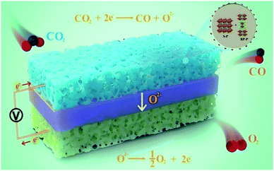
Herein, the in situ construction of hetero-structured DP/RP-SFCuM composites with exsolved Fe–Cu bimetallic nanoparticles was proposed with one-step treatment of the Sr2Fe1.25Cu0.25Mo0.5O6−σ perovskite under reducing conditions at high temperatures. Subsequently, the effects of the phase evolution on the crystal and the physical and chemical properties were thoroughly analyzed, and the catalytic performances of the resultant electrode in CO2 electrolysis reactions were systematically evaluated. A schematic illustration of the cell configurations of the SOECs for CO2 electrolysis is shown in Scheme 1. The hetero-structured DP/RP-SFCuM perovskite composites with exsolved Fe–Cu bimetallic nanoparticles exhibit excellent electrochemical performance in CO2 electrolysis reactions. At 800 °C, the CO2 electrolysis current density is equal to approximately 1.7 and 2.5 A cm−2 at an applied potential of 1.4 and 1.5 V, respectively, which is superior to that of single cells with DP-SFCuM as the cathode and other promising electrodes, demonstrating that it is an efficient CO2 electrolysis electrocatalyst for high-performance SOECs.
2 Experimental section
2.1 Material preparation
Sr2Fe1.5Mo0.5O6−δ (SFM) and Sr2Fe1.25Cu0.25Mo0.5O6−δ (SFCuM) powders were prepared by the combustion method.30 During the preparation, the starting materials were H24Mo7N6O24, Cu(NO3)2·9H2O and Fe(NO3)3·9H2O (all more than 99.9% pure) as well as Sr(NO3)2 (99.5% pure). The chelating agents were citric and ethylene diamine tetra-acetic acids. After synthesis, the powders were obtained by firing at 1000 °C for 10 h. Similar preparation procedures were applied for the synthesis of La0.4Ce0.6O2−δ, Sm0.2Ce0.8O1.9 and La0.58Sr0.4Co0.2Fe0.8O3−δ powders.2.2 Cell preparation and electrochemical testing
La0.8Sr0.2Ga0.8Mg0.2O3−δ (LSGM)-based electrolyte, which supported a single SOEC, was used to evaluate the performance of the catalyst during the CO2 electrolysis. Firstly, the LSGM electrolytes (the powders were bought from Wuxi city Kaistar Electro-Optic Materials Co., Ltd., and the average particle size is about 3 μm with a purity of about 99.9%) were dry-pressed and heated at 1500 °C for 6 h, followed by polishing to ∼250 μm. Then, La0.4Ce0.6O2−σ (LDC) was applied to one side of the electrolyte and heated at 1400 °C for 2 h. Next, the cathode pastes were coated on the LDC layer and heated at 1150 °C for 2 h. Subsequently, LSCF-SDC anode paste was applied to another solid electrolyte side and sintered at 1100 °C for 2 h. To evaluate the catalytic activities of the obtained electrodes in terms of the CO2 reduction reaction, LSGM electrolyte-supported symmetrical cells in a 1![[thin space (1/6-em)]](https://www.rsc.org/images/entities/char_2009.gif) :
:![[thin space (1/6-em)]](https://www.rsc.org/images/entities/char_2009.gif) 1 CO–CO2 atmosphere are applied. Ag paste (covering 0.215 cm2 area) served as a current collector.
1 CO–CO2 atmosphere are applied. Ag paste (covering 0.215 cm2 area) served as a current collector.
Then, the single SOEC was sealed in an Al2O3 tube using a Cerama-bond 552-VFG sealant (Aremco) and heated to 850 °C. Prior to the tests, the cathodes were conditioned in H2 containing 3% of H2O for 2 h. The cell performance towards CO2 electrolysis was then evaluated when the cathode was changed to a pure CO2 environment. During testing, the LSV and EIS data (105 to 0.01 Hz) were collected at 700–850 °C. After testing, an equivalent circuit was decided by using RelaxIS3.0 software (Germany). The electrical surface exchange coefficient (kq) was then calculated using eqn (1):26,27,31
| kq = RT/4F2RAelectrode × c0 | (1) |
The gas product was determined by gas chromatography (performed using a GC2060 instrument manufactured in China). The gas flow rate was determined using a flowmeter. The Faraday efficiency was calculated as follows:32
 | (2) |
2.3 Material characterization
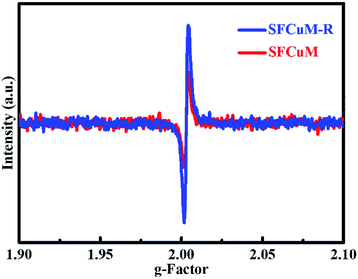
The materials synthesized in this work were characterized by XRD (Miniflex600, Japan), HR-TEM (performed using a JEM-F200 instrument manufactured in Japan), and SEM (performed using an APREOS instrument, manufactured in the Netherlands). The O vacancy concentration was analyzed by EPR (EMXmicro-6/1/P/L, Germany). The chemical states of the Sr, Fe, Mo, Cu and O elements were analyzed by XPS (ESCALAB 250Xi). RelaxIS3.0 software (Germany) was used to analyze the EIS data, and the detailed parameters about the DRT analysis are as follows: (basic function: Gaussian; lambda: 0.0001; shape factor: 0.5).3 Results and discussion
3.1 Crystal structure and morphology of the catalysts
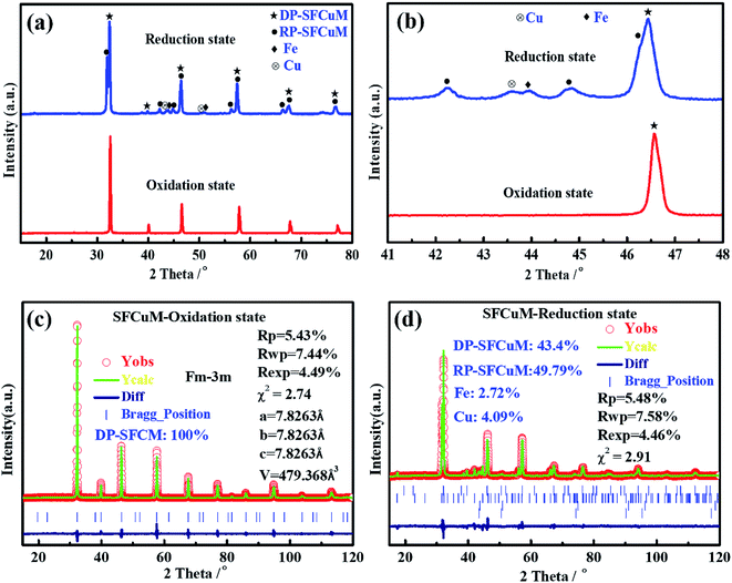
As shown in Fig. 1(a) and (c), the as-synthesized Sr2Fe1.25Cu0.25Mo0.5O6−σ (SFCuM) powders in the oxidation state exhibit a pure perovskite phase (DP-SFCuM), which crystallizes in a cubic Fm![[3 with combining macron]](https://www.rsc.org/images/entities/char_0033_0304.gif) m space group with a lattice constant of a = b = c = 0.782 nm. However, after reduction under a H2 atmosphere at 850 °C for 2 h, phase evolution occurs. In addition to the DP-SFCuM phase (43.4%), the Ruddlesden–Popper layered perovskite of Sr3Fe2−x−yCuxMoyO7−σ (RP-SFCuM, 49.79%) and Cu–Fe bimetal phases (Fe: 2.72% and Cu: 4.09%) could also be clearly detected (Fig. 1(b) and (d)); this result is slightly different from that of the sample without Cu doping (Fig. S1†), where only exsolved Fe metal is clearly detected.
m space group with a lattice constant of a = b = c = 0.782 nm. However, after reduction under a H2 atmosphere at 850 °C for 2 h, phase evolution occurs. In addition to the DP-SFCuM phase (43.4%), the Ruddlesden–Popper layered perovskite of Sr3Fe2−x−yCuxMoyO7−σ (RP-SFCuM, 49.79%) and Cu–Fe bimetal phases (Fe: 2.72% and Cu: 4.09%) could also be clearly detected (Fig. 1(b) and (d)); this result is slightly different from that of the sample without Cu doping (Fig. S1†), where only exsolved Fe metal is clearly detected.
It is worth noting that the peak positions corresponding to the exsolved Cu and Fe metals are clearly separated (Fig. 1(b)), indicating that the Cu and Fe elements exsolved from the parent SFCuM matrix are not in alloy form, which differs significantly from the previous reports such as the exsolved Fe–Ni,19 Fe–Co33 and Cu–Ni alloys.34 This could be because that Cu and Fe atoms are less likely to come together on an atomic basis, resulting in significant fluctuations and phase separation in Fe–Cu alloys.35,36 According to the detected phases in the XRD results, the exsolution process can be expressed using eqn (3):
| Sr2Fe1.25Cu0.25Mo0.5O6−σ (DP-SFCuM) + H2 → Sr3Fe2−x−yCuxMoyO7−σ (RP-SFCuM) + Sr2(Fe1.25Cu0.25Mo0.5)1−zO6−σ (DP-SFCuM) + Cu + Fe + H2O + Vo | (3) |
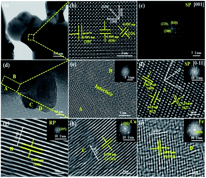
HR-TEM analysis is applied to observe the structural variations in the DP-SFCuM phase induced by the reduction treatment. As shown in Fig. 2, before reduction, only a single phase is observed; the interplanar spacing is approximately 0.39 nm in each direction (see Fig. 2(b)), which is consistent with the [001] zone axis of the cubic SP-SFCuM phase. However, after reduction, the morphology and crystalline structure are obviously changed, as shown in (d–i). Not only are the crystalline structures of DP-SFCuM (part A, indexed as the [0–11] zone axis of the DP-SFCuM phase) and RP-SFCuM (part B, indexed as the (105) lattice plane of the RP-SFCuM phase) observed, but Cu and Fe nanoparticles could also be clearly confirmed (the lattice spacing was 0.208 and 0.203 nm in parts C and D, which corresponds to the (111) plane of Cu and the (110) plane of Fe, respectively). The XRD results shown in Fig. 1 are in good agreement with these results.
Furthermore, the HR-TEM images reveal that the exsolved Cu and Fe bimetal nanoparticles were both effectively fixed in the matrix of the perovskite, showing that the exsolved Cu–Fe bimetal nanoparticles and the perovskite matrix interact strongly. This anchoring effect is critical for improving the stability of metal nanocatalysts under SOEC testing conditions, as it mostly prevents metal nanoparticles from sintering and agglomerating by the perovskite ceramic matrix at higher operating temperatures.14,18
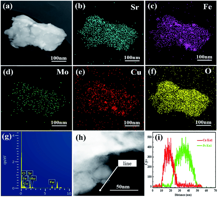
To further determine the distribution of the exsolved nanoparticles in the reduced SFCuM matrix, TEM-EDS elemental mapping was carried out and the results are shown in Fig. 3. On the surface of the matrix particles, a large number of nanosized particles with particle sizes in the range of 10–30 nm is uniformly dispersed. Furthermore, the exsolved nanoparticles include exclusively Cu or Fe metals, whereas other elements are equally distributed in the matrix particles, indicating that these nanoparticles are composed of Fe or Cu metal. Further, TEM-EDS line scanning is performed to determine the atomic fraction of each element in the exsolved nanoparticles. Fig. 3(h) and (i) further confirm that the exsolved nanoparticles are not in alloy form but mainly comprise separated Cu and Fe elements, which is consistent with a previous report.29
As shown in Fig. S2,† when only Fe exsolves from the matrix, the exsolved nanoparticles grow easily and are mainly in the range 50–70 nm. By contrast, in the presence of Fe–Cu bimetals, the average size of the exsolved particles is obviously decreased, and is mainly in the range of approximately 10–30 nm. This suggests that the separated Fe–Cu bimetals are also effective for preventing the metal nanoparticles from sintering and agglomerating at the high temperatures. The separated Fe–Cu bimetals may be due to the fact that Cu and Fe metals are difficult to form alloys, which could be separated each other during the exsolution process, effectively preventing them from agglomerating and sintering at high temperatures. This structural feature is not only beneficial for stability enhancement of the exsolved nano catalysts, but could also provide more metal–oxide interfaces for the adsorption and activation of CO2 molecules in the resultant electrode.15
3.2 Surface chemical states of the catalysts
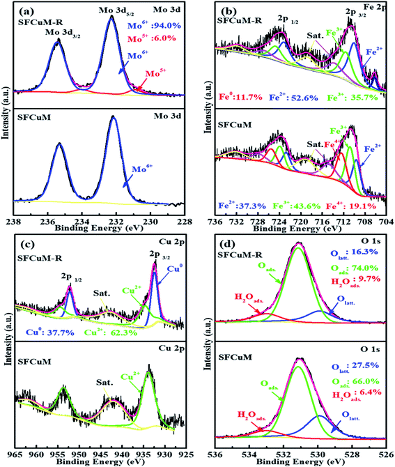
In addition to crystal morphology and structure, the surface chemical states change substantially during reduction. As shown in Fig. 4, the XPS spectra of the Mo cations in the as-synthesized SFCuM sample demonstrate two symmetric peaks at 235.3 and 232.15 eV (Fig. 4(a)), which correspond to Mo6+ electrons 3d3/2 and 3d5/2,37 respectively. The Fe 2p spectrum (Fig. 4(b)) shows two asymmetric peaks, each of which could be deconvoluted into three peaks, each corresponding to the mixed oxidation state of Fe2+/3+/4+.37 The oxidation states corresponding to Mo, Fe, and Cu are all clearly reduced after reduction at 850 °C for 2 h under a H2 atmosphere, especially Fe0 and Cu0 are clearly observed.During reduction, the creation of additional oxygen vacancy defects in the final sample is followed by the formation of lower oxidation state metals (Fig. 5), which is also in good agreement with the variations in the Olatt and Oads shown in Fig. 4(d). After reduction treatment, the amount of Olatt is obviously decreased, whereas that of Oads is greatly increased. Accordingly, the ratio of the Oads/Olatt significantly increases from 2.40 to about 4.54. The high Oads/Olatt peak ratio demonstrates an increased concentration of adsorbed species of oxygen (such as carbonate, O22−, OH−, and O−) at the reduced SFCuM surface. At higher temperatures and in a reducing atmosphere, such weakly adsorbed oxygen species can be easily released,38 leaving a large number of active sites, which would promote full contact between CO2 molecules and active B-site transition metals. Furthermore, the presence of mixed-valent Mo5+/Mo6+ and Fe2+/Fe3+ and large concentrations of oxygen vacancy defects, can result in the ionic and electrical conductivity and catalytic activity necessary for the CO2 electrolysis processes.
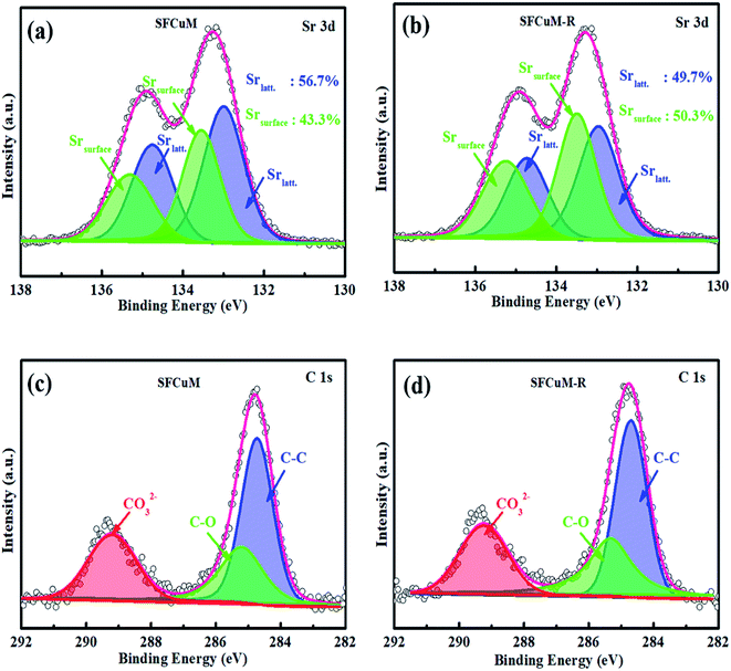
According to the XPS analysis, phase evolution also has a significant impact on the surface composition of the resulting perovskite. As illustrated in Fig. 6(a), the ratio of Srsurface/Srlatt is greatly increased after reduction, wherein Srlatt indicates Sr in the SFCuM lattice, whereas Srsurface comprises mainly surface-bound Sr, such as Sr–OH or Sr–CO3. Because the binding energies for the O 1s core levels in the species CO32− and OH− are almost identical, photoelectron spectroscopy alone is insufficient to distinguish between the hydroxyl and carbonate groups on the surface. Quantitative data, notably the atomic ratio between the C 1s component (only CO32−) at 289.3–289.6 eV and the O-component (OH− + CO32−) at 531.5 eV are utilized to elucidate the aforementioned issue. According to Table S1,† the ratio of O/C is about 3.75 for the reduced SFCuM sample, which is slightly higher than the theoretical value estimated from the stoichiometry of carbonate (O/C in carbonate is 3). This simple assessment shows that the Srsurface comprises both Sr–OH and Sr–CO3, which is consistent with the result shown in Table S2,† where the ratio of CO32−/Sr is about 0.84 on the surface of the reduced SFCuM.
It is probable that the adsorbed carbonate ions should be caused by the enriched alkaline earth element Sr on the surface. According to the surface composition (Table S2†), before reduction, the Sr/(Fe + Mo + Cu) ratio in the SFCuM sample is approximately 1.54, whereas that of the reduced sample increases to approximately 1.93. The increased amount of Sr segregation is closely related to the formation of the RP-SFCuM (Sr3Fe2−x−yCuxMoyO7−σ) phase after reduction, in which the larger A-site Sr cations preferentially dominate the perovskite surface.39,40 The segregated Sr cations on the perovskite surface are also important for the chemical adsorption of CO2 molecules.41,42 A-site alkali and/or alkaline earth oxides such as SrO41 or CaO43 on the perovskite surface has been revealed to improve CO2 adsorption at elevated temperatures, as these metal oxides are alkaline in nature and can adsorb CO2,44 resulting in a highly active surface for CO2 reduction.
3.3 Electrochemical performances of a single SOEC for CO2 electrolysis
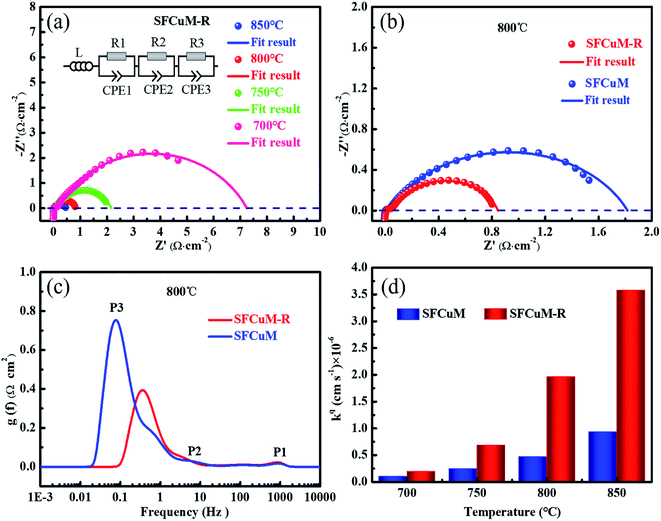
To evaluate the catalytic activities of the SFCuM and SFCuM-R electrodes in terms of the CO2 reduction reaction, their electrochemical impedance spectra (EIS) are obtained using LSGM electrolyte-supported symmetrical cells in a 1![[thin space (1/6-em)]](https://www.rsc.org/images/entities/char_2009.gif) :
:![[thin space (1/6-em)]](https://www.rsc.org/images/entities/char_2009.gif) 1 CO–CO2 atmosphere at different operating temperatures. The discrepancy between the intercepts of the low- and high-frequency arcs with the real axis is regarded as the polarization resistance (Rp) in the EIS, which is defined as a leading parameter for the assessment of electrode electrochemical performance; a smaller Rp value indicates more desirable catalytic activities in electrochemical systems. As shown in Fig. 7, the Rp values of the SFCuM-R electrode are 0.46, 0.81, 2.15 and 7.2 Ω cm−2 at the operating temperatures of 850, 800, 750 and 700 °C, respectively (Fig. 7(a)). This is obviously lower than the Rp values of the SFCuM electrode under the same testing conditions (Fig. S3†), indicating that the catalytic activity for the CO2 reduction reaction in the SFCuM electrode is likely to be enhanced by the reduction treatment.
1 CO–CO2 atmosphere at different operating temperatures. The discrepancy between the intercepts of the low- and high-frequency arcs with the real axis is regarded as the polarization resistance (Rp) in the EIS, which is defined as a leading parameter for the assessment of electrode electrochemical performance; a smaller Rp value indicates more desirable catalytic activities in electrochemical systems. As shown in Fig. 7, the Rp values of the SFCuM-R electrode are 0.46, 0.81, 2.15 and 7.2 Ω cm−2 at the operating temperatures of 850, 800, 750 and 700 °C, respectively (Fig. 7(a)). This is obviously lower than the Rp values of the SFCuM electrode under the same testing conditions (Fig. S3†), indicating that the catalytic activity for the CO2 reduction reaction in the SFCuM electrode is likely to be enhanced by the reduction treatment.
To clarify the origin of the enhancement in catalytic activity, the EIS data are further evaluated according to the distribution of relaxation times (DRTs), as demonstrated in Fig. 7(c). Clearly, the area of the low-frequency peak P3 process is significantly reduced by the reduction treatment, whereas that of the P1 and P2 processes do not change significantly. In addition, in a previous study, it is found that P1 is linked to oxygen ion transportation at the interface between the electrodes and the LSGM electrolyte, whereas P2 is linked to the transfer of O2− in the electrodes, and P3 represents gas convention processes, which include adsorption, activation, and dissociation reactions.11,12,19,45 CO2 adsorption and activation processes are considerably improved by the reduction treatment, as evidenced by the decreased P3 in the SFCuM-R electrode. Besides, it is also obvious that the peak position corresponding to the P3 process greatly shifts toward the high frequency range for the reduced SFCuM-R electrode, suggesting that the electrochemical surface exchange reactions of the gas convention process should also be accelerated by the reduction treatment. The improved gas convention process is not only related to the formation of more metal–oxide interfaces and oxygen vacancy defects during reduction, which supply more active reaction sites for the activation and adsorption of CO2 molecules,15,16 but also to the formation of hetero-structured DP/RP-SFCuM composites by reduction, which exhibit superior electrical surface exchange coefficient (kq, Fig. 7(d)) for enhanced electrochemical surface exchange reactions.26–28,31
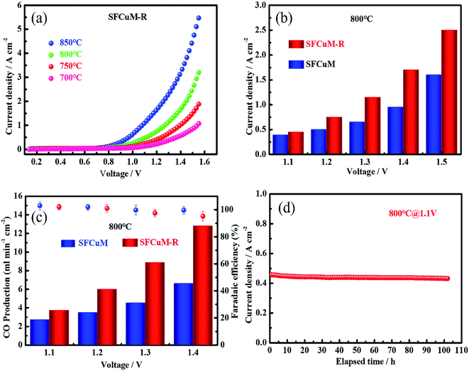
Consequently, the LSGM-electrolyte-supported single cell with SFCuM-R as the cathode and LSCF-SDC as the anode exhibits excellent current density for CO2 electrolysis under a 100% CO2 atmosphere (see Fig. 8(a)). At 800 °C, the CO2 electrolysis current density of the SFCuM-R-containing SOEC is equal to 0.45, 0.75, 1.15, 1.7 and 2.5 A cm−2 at an applied potential of 1.1, 1.2, 1.3, 1.4 and 1.5 V, respectively, which is superior to that of the single cell with SFCuM and SFM-R as the cathodes (see Fig. 8(b), S4 and S5†). Furthermore, these values are also comparable to those of other prospective perovskite electrodes (see Table S3†). Additionally, the single cell with the SFCuM-R electrode also exhibits high current efficiency for CO2 to CO conversion at different potentials. As shown in Fig. 8(c), the CO production gradually increases with increasing applied potential, whereas the corresponding faradaic efficiency decreases slightly. However, even at an applied potential of 1.4 V, the CO production and faradaic efficiency are still as high as 12.8 ml min−1 cm−2 and 95.2%, respectively. Besides, the obtained SFCuM-R electrode exhibits excellent long-term stability during CO2 electrolysis. As shown in Fig. 8(d), the current density stabilizes at around 0.43 A cm−2 under a pure CO2 atmosphere at 800 °C and shows no prominent degradation following 100 h of examination. After the long-term stability testing, no obvious carbon formation and delamination are observed (Fig. S6 and S7†), suggesting that the hetero-structured DP/RP-SFCuM composite with exsolved Fe–Cu bimetal nanoparticles is a promising CO2 electrolysis electrocatalyst for high performance SOECs.
4 Conclusions
The in situ construction of hetero-structured DP/RP-SFCuM composites with exsolved Cu–Fe bimetal nanoparticles is successfully achieved by one-step reduction treatment of the Sr2Fe1.25Cu0.25Mo0.5O6−σ (SFCuM) perovskite at a temperature of 850 °C for 2 h. The LSGM-electrolyte-supported single cell with the obtained composite as the cathode exhibits excellent electrochemical performance for CO2 electrolysis. At an operating temperature of 800 °C, the CO2 electrolysis current density is as high as 1.7 and 2.5 A cm−2 at the applied potentials of 1.4 and 1.5 V, respectively, which is superior to that of a single cell with DP-SFCuM as the cathode. The improved electrochemical performance is directly related to the formation of abundant metal–oxide interfaces and oxygen vacancy defects, as well as the combination of oxide heterostructures. These results demonstrate that hetero-structured DP/RP-SFCuM composites with exsolved Cu–Fe bimetal nanoparticles are very efficient CO2 electrolysis electrocatalysts for high-performance SOECs.Conflicts of interest
There are no conflicts of interest to declare.Acknowledgements
This work was financially supported by the National Natural Science Foundation of China (No. 21975163), Natural Science Foundation of Guangdong Province of China (2020A1515011165) and Shenzhen Science and Technology Program (No. KQTD20190929173914967). The authors sincerely acknowledge the generosity of the Instrumental Analysis Center of Shenzhen University (Xili Campus) and Sinoma Institute of Materials Research (Guang Zhou) Co., Ltd. for HR-SEM and HR-TEM measurements. The authors also would like to thank Xinfang Cui from Shiyanjia Lab (www.shiyanjia.com) for the EPR and XPS measurements.References
- W. Li and J.-L. Luo, Electrochem. Energy Rev., 2021, 4, 518–544 CrossRef CAS.
- Y. Song, X. Zhang, K. Xie, G. Wang and X. Bao, Adv. Mater., 2019, 31, e1902033 CrossRef PubMed.
- F. Cheng, X. Duan and K. Xie, Angew. Chem., 2021, 133, 18940–18947 CrossRef.
- M. Zheng, S. Wang, Y. Yang and C. Xia, J. Mater. Chem. A, 2018, 6, 2721–2729 RSC.
- Y. Song, Z. Zhou, X. Zhang, Y. Zhou, H. Gong, H. Lv, Q. Liu, G. Wang and X. Bao, J. Mater. Chem. A, 2018, 6, 13661–13667 RSC.
- J. Zhu, W. Zhang, Y. Li, W. Yue, G. Geng and B. Yu, Appl. Catal., B, 2020, 268, 118389 CrossRef CAS.
- H. Li, T. Liu, P. Wei, L. Lin, D. Gao, G. Wang and X. Bao, Angew. Chem., Int. Ed., 2021, 60, 14329–14333 CrossRef CAS PubMed.
- D. Huan, L. Zhang, S. Zhang, N. Shi, X. Li, K. Zhu, C. Xia, R. Peng and Y. Lu, J. Mater. Chem. A, 2021, 9, 2706–2713 RSC.
- Y. Zhou, Z. Zhou, Y. Song, X. Zhang, F. Guan, H. Lv, Q. Liu, S. Miao, G. Wang and X. Bao, Nano Energy, 2018, 50, 43–51 CrossRef CAS.
- L. Ye, M. Zhang, P. Huang, G. Guo, M. Hong, C. Li, J. T. Irvine and K. Xie, Nat. Commun., 2017, 8, 14785 CrossRef CAS PubMed.
- Y. Li, Y. Li, Y. Wan, Y. Xie, J. Zhu, H. Pan, X. Zheng and C. Xia, Adv. Energy Mater., 2019, 9, 1–10 Search PubMed.
- Y. Jiang, Y. Yang, C. Xia and H. J. M. Bouwmeester, J. Mater. Chem. A, 2019, 7, 22939–22949 RSC.
- C. Zhu, S. Hou, X. Hu, J. Lu, F. Chen and K. Xie, Nat. Commun., 2019, 10, 1173 CrossRef PubMed.
- J. T. S. Irvine, D. Neagu, M. C. Verbraeken, C. Chatzichristodoulou, C. Graves and M. B. Mogensen, Nat. Energy, 2016, 1, 1–13 Search PubMed.
- H. Lv, L. Lin, X. Zhang, Y. Song, H. Matsumoto, C. Zeng, N. Ta, W. Liu, D. Gao, G. Wang and X. Bao, Adv. Mater., 2020, 32, 1–9 Search PubMed.
- H. Lv, T. Liu, X. Zhang, Y. Song, H. Matsumoto, N. Ta, C. Zeng, G. Wang and X. Bao, Angew. Chem., Int. Ed., 2020, 59, 15968–15973 CrossRef CAS PubMed.
- D. J. Deka, J. Kim, S. Gunduz, M. Aouine, J.-M. M. Millet, A. C. Co and U. S. Ozkan, Appl. Catal., B, 2021, 286, 119917 CrossRef CAS.
- J. H. Myung, D. Neagu, D. N. Miller and J. T. Irvine, Nature, 2016, 537, 528–531 CrossRef CAS PubMed.
- H. Lv, L. Lin, X. Zhang, D. Gao, Y. Song, Y. Zhou, Q. Liu, G. Wang and X. Bao, J. Mater. Chem. A, 2019, 7, 11967–11975 RSC.
- Y. Li, B. Hu, C. Xia, W. Q. Xu, J. P. Lemmon and F. Chen, J. Mater. Chem. A, 2017, 5, 20833–20842 RSC.
- J. Lu, C. Zhu, C. Pan, W. Lin, J. P. Lemmon, F. Chen, C. Li and K. Xie, Sci. Adv., 2018, 4, 1–8 CAS.
- Y. Jiang, F. Chen and C. Xia, J. Power Sources, 2021, 493, 229713 CrossRef CAS.
- J. Ko, B.-K. Kim and J. W. Han, J. Phys. Chem. C, 2016, 120, 3438–3447 CrossRef CAS.
- C. Zhao, Y. Li, W. Zhang, Y. Zheng, X. Lou, B. Yu, J. Chen, Y. Chen, M. Liu and J. Wang, Energy Environ. Sci., 2020, 13, 53–85 RSC.
- Y. Zheng, Z. Chen and J. Zhang, Electrochem. Energy Rev., 2021, 4, 508–517 CrossRef CAS.
- Y. Zheng, Y. Li, T. Wu, W. Zhang, J. Zhu, Z. Li, J. Chen, B. Yu, J. Wang and J. Zhang, Nano Energy, 2018, 51, 711–720 CrossRef CAS.
- Y. Zheng, C. Zhao, Y. Li, W. Zhang, T. Wu, Z. Wang, Z. Li, J. Chen, J. Wang, B. Yu and J. Zhang, Nano Energy, 2020, 78, 105236 CrossRef CAS.
- M. Sase, F. Hermes, K. Yashiro, K. Sato, J. Mizusaki, T. Kawada, N. Sakai and H. Yokokawa, J. Electrochem. Soc., 2008, 155, B793 CrossRef CAS.
- Y. Song, Y. M. Yin, L. Li, Z. Chen and Z. F. Ma, Chem. Commun., 2018, 54, 12341–12344 RSC.
- X. Xi, J. Liu, Y. Fan, L. Wang, J. Li, M. Li, J.-L. Luo and X.-Z. Fu, Nano Energy, 2021, 82, 105707 CrossRef CAS.
- Y. Zheng, Y. Li, T. Wu, C. Zhao, W. Zhang, J. Zhu, Z. Li, J. Chen, J. Wang, B. Yu and J. Zhang, Nano Energy, 2019, 62, 521–529 CrossRef CAS.
- S. Liu, Q. Liu and J.-L. Luo, J. Mater. Chem. A, 2016, 4, 17521–17528 RSC.
- X. Xi, X.-W. Wang, Y. Fan, Q. Wang, Y. Lu, J. Li, L. Shao, J.-L. Luo and X.-Z. Fu, J. Power Sources, 2021, 482, 228981 CrossRef CAS.
- D. Li, M. Lu, K. Aragaki, M. Koike, Y. Nakagawa and K. Tomishige, Appl. Catal., B, 2016, 192, 171–181 CrossRef CAS.
- H. Wang and B. Wei, Chin. Sci. Bull., 2011, 56, 3416–3419 CrossRef CAS.
- K. Yuge, A. Seko, I. Tanaka and S. R. Nishitani, Phys. Rev. B: Condens. Matter Mater. Phys., 2005, 72, 174201 CrossRef.
- Z. Du, H. Zhao, S. Li, Y. Zhang, X. Chang, Q. Xia, N. Chen, L. Gu, K. Świerczek, Y. Li, T. Yang and K. An, Adv. Energy Mater., 2018, 8, 1800062 CrossRef.
- M. Zhi, G. Zhou, Z. Hong, J. Wang, R. Gemmen, K. Gerdes, A. Manivannan, D. Ma and N. Wu, Energy Environ. Sci., 2011, 4, 139–144 RSC.
- F. Sher, A. J. Williams, A. Venimadhev, M. G. Blamire and J. P. Attfield, Chem. Mater., 2005, 17, 1792–1796 CrossRef CAS.
- T. Chakraborty, C. Meneghini, A. Nag and S. Ray, J. Mater. Chem. C, 2015, 3, 8127–8131 RSC.
- L. Ye, C. Pan, M. Zhang, C. Li, F. Chen, L. Gan and K. Xie, ACS Appl. Mater. Interfaces, 2017, 9, 25350–25357 CrossRef CAS PubMed.
- H. Falcon, Appl. Catal., B, 2004, 53, 37–45 CrossRef CAS.
- Y. Tian, L. Zhang, Y. Liu, L. Jia, J. Yang, B. Chi, J. Pu and J. Li, J. Mater. Chem. A, 2019, 7, 6395–6400 RSC.
- J. D. Kirtley, S. N. Qadri, D. A. Steinhurst and J. C. Owrutsky, J. Power Sources, 2016, 336, 54–62 CrossRef CAS.
- X. Zhang, Y. Song, F. Guan, Y. Zhou, H. Lv, Q. Liu, G. Wang and X. Bao, J. Power Sources, 2018, 400, 104–113 CrossRef CAS.
Footnote |
| † Electronic supplementary information (ESI) available. See DOI: 10.1039/d1ta07678g |
| This journal is © The Royal Society of Chemistry 2022 |

