
 Open Access Article
 This Open Access Article is licensed under a
 Creative Commons Attribution 3.0 Unported Licence
Building a DC electric field-driven wheat leaf-like surface pattern with a cholesteric liquid crystal fluoropolymer for directional droplet manipulation†
Deyan
Li‡
ab,
Zhijian
Mai‡
ab,
Yancong
Feng‡
 ab,
Hui
Min
ab,
Jinglun
Liao
ab,
Yao
Wang
*ab,
Hao
Li
*ab and
Guofu
Zhou
ab
ab,
Hui
Min
ab,
Jinglun
Liao
ab,
Yao
Wang
*ab,
Hao
Li
*ab and
Guofu
Zhou
ab
aGuangdong Provincial Key Laboratory of Optical Information Materials and Technology & Institute of Electronic Paper Displays, South China Academy of Advanced Optoelectronics, South China Normal University, Guangzhou 510006, China. E-mail: wangyao@m.scnu.edu.cn; haoli@m.scnu.edu.cn
bNational Center for International Research on Low-energy Optoelectronics, South China Normal University, Guangzhou 510006, China
First published on 12th August 2022
Abstract
As the most common natural act, precise manipulation of directional droplet motion has widely been mimicked for fabricating smart materials and devices. In this work, we built a direct current (DC) electric field-driven preconfigured surface pattern with a fluorinated cholesteric liquid crystal polymer. This solid pattern could be actuated by a one-side DC electric field (field strength threshold: 1.67 V μm−1), along with the emergence of a visible wheat leaf-like topography (maximum deformation index: 10%). Simultaneously, these patterned embossments rendered the coating surface hydrophobic enough to trigger the directional motion of water droplets on account of the wettability variation, weakened contact angle hysteresis, and drainage effect. This study presents a facile and practical strategy for constructing solid patterns for precise and low-energy droplet manipulation.
Introduction
The motion of droplets, especially directional motion, is a common but crucial phenomenon in nature. Many natural materials and creatures are innately capable of driving droplets directionally and spontaneously.1 Nowadays, the directional droplet motion based on bioinspired materials and technologies is being realized and has gradually developed into droplet manipulation available for heat transfer, water harvest, self-cleaning, microfluidics, biomedical applications,1–3 and even electricity generation.4In general, there are two approaches to control macroscopic droplet motion: one is to apply an external physical stimulus or physical field to drive the droplet, e.g. magnetism,5,6 heat,7,8 light,9 sound,10,11 and electricity;12–15 the other is to construct chemical and structural gradient surfaces, including microscopic charge,16 wettability,17 topography,18–20 and multiple gradients.21 The latter treatment naturally creates surface tensions or surface energy gradients to bring a driving force for self-propelled droplet motion.22 For example, a wheat leaf is covered by hierarchical micropapillae and longitudinal grooves and has a natural surface with anisotropic superhydrophobicity and low adhesion for directional droplet motion.23 In recent years, an integrated strategy has been invented, in which droplets could be directionally guided by physical field-controlled surface topography. Yu et al. manipulated fluid transport based on photo-induced asymmetric deformation of a liquid crystal (LC) polymer microtube.24 Jia et al. carried out temperature management to trigger the self-propelled motion of the Leidenfrost droplets on ratchet surfaces.25 More complicated materials and surface topographies were demanded in both studies.
Is there any facile way to obtain a precisely manipulable surface? As we know, LC is one of the most promising materials to build such surfaces owing to its inherent high anisotropy, oriented alignment and synergistic movement in physical fields.24,26,27 A LC will easily undergo phase transition which could change its own optical, mechanical, and even morphological features once a physical field is applied. Among various physical stimuli, the electric field combines feasibility with high efficiency to induce reorientation of LC molecules with high dielectric anisotropy.28–31 It is well known that the effect of an alternating current (AC) electric field is dominated by the bulk conduction process and the oscillating resonance to the polar rigid core of LC molecules.32,33 For example, Broer et al. created regular embossments with over 100 nm height on the surface of a 2.5 μm thick LC polymer film after applying an AC electric field of 7.5 V μm−1 at 900 kHz.29 Meanwhile, it is also known that periodic AC puts the conduction process in a temporary state,33 possibly causing those emerged embossments to be unstable and unreproducible, which impedes its applications in programmable and subtle patterning with precise surface topographies. As we mentioned earlier, building such surfaces (e.g. wheat leaf) is mostly required for directional droplet manipulation in practice.1 Different from an AC electric field, direct current (DC) with inherent unidirectionality can create a directional flow field to provide a driving force toward denser configurations, even highly oriented and ordered LC self-assemblies.28,34–36 Besides, given its good controllability, high stability and low energy consumption,37 a DC electric field shows huge potential for generating precise and low-energy LC surface patterning. To the best of our knowledge, the work adopting a DC electric field to implement preconfigured LC surface patterns has not been reported so far.
In this study, we first designed and synthesized a fluorinated cholesteric LC polymer (CLCP) with strong dielectric anisotropy and integrated it with a plate interdigitated electrode to build a DC electric field-responsive coating (see Fig. 1). As expected, under electric actuation with a low electric field strength of 3.33 V μm−1, many visible and arrayed strip embossments emerged above the solid coating, like the surface topography of a wheat leaf. The embossing of these “strips” rendered the coating surface hydrophobicity to trigger the motion of water droplets successfully.
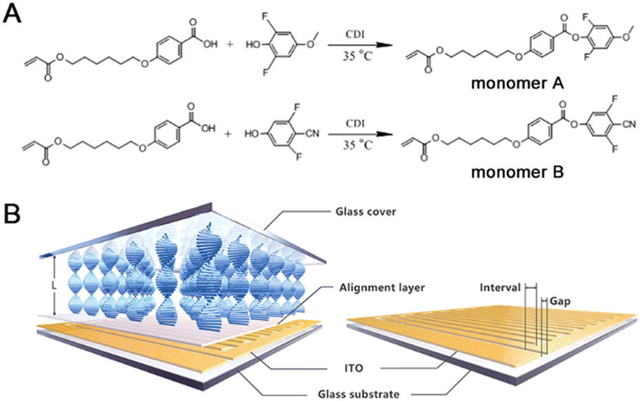 | ||
| Fig. 1 Synthetic routes of monomer A and monomer B (A); structure diagram of horizontally aligned CLCP coating over the transparent interdigitated comb-shape electrode (conducting layer: indium tin oxide (ITO); gap: 30 μm; interval: 30, 60 and 120 μm) (B). | ||
Experimental
Materials
4-(6-Acryloyloxy-hexyloxy)-benzoic acid (98%, Jinnan TYPE Chemical Co., Ltd, Jinnan, P. R. China), 2, 6-difluoro-4-methoxyphenol (97%, Alfa Aesar, Thermo Fisher Scientific Inc, Shanghai, P. R. China), N,N′- carbonyldimidazole (CDI; 97%; Shanghai Macklin Biochemical Co., Ltd, Shanghai, P. R. China), 4-(6-acryloyloxy-hexyloxy)-benzonic acid and 3, 5-difluoro-4-cyanophenol (98%, Shanghai Yingrui Chemical Technology Co., Ltd, Shanghai, P. R. China) were directly used without any further purification. Both 2-methyl-1,4-phenylene bis(4-((6-(acryloyloxy)hexyl)oxy)benzoate) (99%) as a cross-linker and (3S,3aS,6R,6aR)-3-((4-((4-(((4-(acryloyloxy)butoxy)carbonyl)oxy)benzoyl)oxy)benzoyl)oxy)hexahydro-2H-cyclopentafuran-6-yl 4-(((3-(acryloyloxy)propoxy)carbonyl)oxy)benzoate (99%) as a chiral dopant were purchased from Jiangsu Hecheng Display Technology Co., Ltd (Nanjing, P. R. China). The photo initiator, (2,4,6-trimethylbenzoyl)phosphine oxide (99%), was obtained from Tianjin Heowns Biochemical Technology Co., Ltd (Tianjin, P. R. China). The inhibitor, p-methoxyphenol (97%), was provided by Adamas Beta Reagent Co., Ltd (Shanghai, P. R. China). The silylating reagent, dichlorodimethylsilane (99%), was purchased from J&K Scientific Ltd (Beijing, P. R. China). Two liquid crystal aligning agents, polyvinyl alcohol (PVA; Acros Organics, 78% hydrolyzed, 6000 g mol−1) and vertically aligned polyimide (PI; DL-4018), were provided by Thermo Fisher Scientific Int. (Geel, Belgium) and Shenzhen Dalton Electronic Materials Co., Ltd (Shenzhen, P. R. China), respectively. Three gap control spacers (SP-205, 5 μm; SP-215, 15 μm; GS-235, 35 μm) for fabrication of liquid crystal cells were provided by SEKISUI Chemical Co., Ltd (Osaka, Japan). All other reagents and organic solvents were of analytic grade and dried or redistilled before use. As a control, corresponding fluorine-free liquid crystal (LC) molecules, i.e., 4-(4-(6-acryloyloxyhexyloxy)benzoyloxy)methoxybenzene (HCM-021) and 4-cyanopheny1-4′-(6-acryloyloxyhexyloxy)benzoate (HCM-020), were provided by Jiangsu Hecheng Display Technology Co., Ltd (Nanjing, P. R. China).Moreover, silica gel (200–300 meshes) was produced from Qingdao Haiyang Chemical Co., Ltd (Qingdao, P. R. China). Glass column for silica gel chromatography (30 cm × φ 3.2 cm) and sand core funnel (φ 9.0 cm; 500 mL) was obtained from Beijing Synthware Glass Instrument Co., Ltd (Beijing, P. R. China). The specific indium tin oxide (ITO) glass plates (3.0 cm × 3.0 cm; thickness: 1.1 mm; ITO coating thickness: 25 ± 5 nm; area resistance 70–100 Ω □−1; transmittance550nm ≥ 87%) with two interdigitated comb-shape electrodes (Gap: 30 μm; interval: 30, 60, and 90 μm) shown in Fig. 1B were customized by Shenzhen Leaguer Optronics Co., Ltd (Shenzhen, P. R. China). Both ultra-clear glass (thickness: 1.1 mm; transmittance550nm: ∼94%) and ITO glass (thickness: 1.1 mm; area resistance: <10 Ω □−1; transmittance550nm: ∼77%) were provided by Luoyang Guluoglass Co., Ltd (Luoyang, P. R. China).
Syntheses and characterizations of fluorinated LC monomers
Two fluorinated cholesteric liquid crystal monomers were synthesized by the esterification reaction (see Fig. 1A). All the detailed procedures were described below.Afterwards, 0.56 g of 2, 6-difluoro-4-methoxyphenol (3.5 mmol) was mixed into the above solution and reacted for 3 hours at 35 °C. The product was purified by silica gel column chromatography using ethyl acetate-petroleum ether (1![[thin space (1/6-em)]](https://www.rsc.org/images/entities/char_2009.gif) :5, v/v) at room temperature. Yield: 0.70 g (35.0%). 1H-NMR (400 MHz, deuterated dimethylsulfoxide, namely d6-DMSO; see Fig. S1, ESI†): δ = 8.05 (d, 2H), 6.93 (d, 1H), 6.57 (d, 1H), 6.41 (s, 1H), 6.13 (t, 1H), 5.82 (d, 1H), 4.18 (t, 2H), 4.03 (t, 2H), 3.73 (s, 3H), 1.72 (m, 2H), 1.56 (m, 2H), 1.27 (m, 4H).
:5, v/v) at room temperature. Yield: 0.70 g (35.0%). 1H-NMR (400 MHz, deuterated dimethylsulfoxide, namely d6-DMSO; see Fig. S1, ESI†): δ = 8.05 (d, 2H), 6.93 (d, 1H), 6.57 (d, 1H), 6.41 (s, 1H), 6.13 (t, 1H), 5.82 (d, 1H), 4.18 (t, 2H), 4.03 (t, 2H), 3.73 (s, 3H), 1.72 (m, 2H), 1.56 (m, 2H), 1.27 (m, 4H).
Nuclear magnetic resonance spectroscopy (NMR)
1H-NMR and 13C-NMR spectra of two key fluorinated LC monomers were scanned using d6-DMSO (99%, J&K Scientific Ltd, Beijing, P. R. China) as a solvent and tetramethylsilane (TMS) as an internal standard, via Varian 400 MHz (USA) and Bruker AVANCE NEO 600 MHz NMR system (Germany), respectively.Liquid chromatogram-mass spectrum (LC-MS)
The LC-MS of monomer A and B were carried out using liquid chromatography-triple quadrupole mass spectrometry (TSQ Endura, Thermo Fisher Scientific Inc, USA). The solvent used is methanol (99.9%, Merck, Germany).Differential scanning calorimetry (DSC)
The thermal analyses of monomer A and B were carried out using DSC (DSC1, METTLER TOLEDO, Switzerland) under nitrogen gas (flow rate: 40 mL min−1). Typically, 10 mg of the sample was heated or cooled in the temperature range between 0 and 120 °C at a rate of 5 °C min−1. The phase-transition temperatures, including melting temperature from crystalline to cholesteric phase (Tm), and clear point temperature from the cholesteric to the isotropic phase (TNI), were determined from the peak value of the exothermic peak in the heating run.Density functional theory (DFT) calculations
Geometry optimizations were adopted using the B3LYP (Becke's parameters & Lee-Yang-Parr) exchange-correlation functional with Grimme's DFT-D3 (BJ) empirical dispersion correction. The ma-TZVP basis set was performed, which is the “minimally augmented” version of the def2-TZVP basis set. The DFT calculations were performed with Gaussian.Preparation and characterizations of cholesteric LC fluoropolymer coating
The CLCP coating with the optimized formula shown in Scheme 1 and Fig. S1 (ESI†) was obtained by photocuring and following thermocuring in the predetermined LC cell. The whole preparation process was detailed below.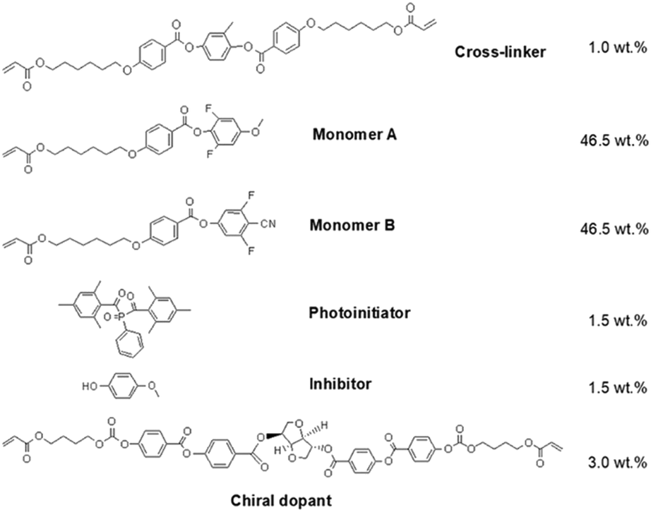 | ||
| Scheme 1 Chemical compositions of DC electric field-driven fluorinated CLCP Coating. | ||
Fabrication of LC cells
The adopted LC cells were composed of two parallel glass plates (3.0 cm × 3.0 cm) with the fixed spacing distance determined by the gap control spacer (5, 15, and 35 μm). Hereinto, the top inner surface was the silylated ultra-clear glass, and the bottom one was the horizontally aligned PVA layer or the vertically aligned PI layer coated on the ITO glass substrate.Typically, the ultra-clear glasses as the cover plate were immersed into the methyl alcohol solution of dichlorodimethylsilane (6 vol%) for 10 minutes and then thoroughly rinsed by methyl alcohol. Finally, surface silanization treatments were completed after natural drying following baking at 100 °C for 2 hours. The horizontally aligned PVA layer was prepared by a spin coating of PVA aqueous solution (5 wt%) on the customized ITO glass plate, using a spin coater (KW-4A, Institute of Microelectronics of the Chinese Academy of Sciences, Beijing, P. R. China) with a fixed rotating speed of 2000 rpm for 30 seconds. The resulting PVA solution layer was heated at 60 °C for 1 hour, using a heating stage [SmartLab HP-303DU, Strider Instrument & Application Co.(Shanghai) Ltd, Shanghai, P. R. China], and then rubbed unidirectionally with a polyester fabric to form the determined alignment layer. Similarly, the vertically aligned PI layer was prepared by spin coating of PI solution, using a spin coater with a fixed rotating speed of 2500 rpm for 60 seconds, and then baking at 105 °C for 30 minutes and at 235 °C for 1.5 hours.
Coating preparation
The LC mixture with the optimized formula shown in Scheme 1 was heated for 30 minutes to exceed the TNI of two host LC monomers (see Fig. S7 and S8, ESI†), via a heating stage [HP-303DU, Strider Instrument & Application Co.(shanghai), Ltd, Shanghai, P. R. China]. Then, the internal space of the LC cell was filled with the hot mixture through the capillary force. Once cooling down below TNI, the filler is completely polymerized using an ultraviolet light curing system [FU3228-A, BANGWO (Guangzhou) Elec. Technologies Co., Ltd, Guangzhou, P. R. China] with the fixed irradiation intensity of 38 mW cm−2 for 300 seconds, and following thermocuring by heating stage at 100 °C for 2 hours. Finally, the surface-silylated cover plate was slightly removed to expose the CLCP coating. As a control, the fluorine-free CLCP coating with the optimized formula shown in Scheme S1 (ESI†) also showed the same results.DSC
The same thermal scanning was carried out for the resulting CLCP coating. The value of the endothermic peak represents the phase-transition temperature. The phase-transition temperatures, including glass transition temperature (Tg), crystallization temperature (Tc), Tm, and TNI, were determined from the peak value of the exothermic peak in the heating run.Polarizing optical microscope (POM)
All the optical phenomena of the fluorinated LC monomers and the resulting CLCP coating were photographed using a POM (DM2700p, Leica, Germany). For observation of stimulus-responsive behaviors, heating of the samples was carried out via an equipped cooling–heating stage (THMS 600, Linkam, UK), and an applied electric field on the samples was supplied via a digital regulated DC power supply (CE0400010T, Earthworm Electronics, P. R. China) or a waveform generator (DG822, Rigol technologies Inc., P. R. China) connected with a signal amplifier (ATA-2021H, Xi’an Aigtek Electronic Technology Co., Ltd, P. R. China).Capacitor measurements
The capacitor measurements were performed by inputting signal of alternating current (AC; 0.5 V, 1 kHz) using an impedance analyzer (6500B, WAYNE KERR, London, UK). The positive pole of the impedance analyzer was attached to the platinum (Pt) probe that was inserted into a 10 μL droplet of 0.1 M sodium chloride (NaCl) aqueous solution on the upper surface of the CLCP coating, and the negative pole was attached to the ITO side of the unpatterned substrate. Here, two formulas (i.e., fluorine-free and fluorinated CLCP coatings) and two alignments (i.e., horizontally aligned and vertically aligned CLCP coatings) were involved. The real-time capacity values (C) were determined on the impedance analyzer until remaining constant. Finally, the dielectric constant (ε) was calculated by eqn (1):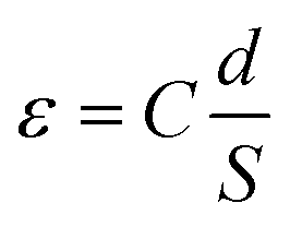 | (1) |
Surface properties of cholesteric LC fluoropolymer coating
000000 pixels (iPhone 7 Plus, Apple, USA). Another unactuated sample was established next to the target one as a control.
000000 pixels (iPhone 7 Plus, Apple, USA). Another unactuated sample was established as a control. The same tests were carried out at least 3 times to obtain the average condensation mass.
Results and discussion
It is well known that lateral fluorination has been adopted in combination with a polar terminal group to enhance molecular dipole moment (μ) and dielectric anisotropy (Δε).38 So, we introduced two fluorine atoms symmetrically into the terminal aromatic rings of the fluorine-free LC molecules, i.e., 4-(4-(6-acryloyloxyhexyloxy)benzoyloxy)methoxybenzene (HCM-021) and 4-cyanopheny1-4′-(6-acryloyloxyhexyloxy)benzoate (HCM-020), respectively. The corresponding fluorinated products were synthesized and characterized. It is shown that: for monomer A, melting temperature (Tm) and clear point temperature (TNI) are 52.30 and 82.87 °C (see Fig. S7, ESI†), respectively; for monomer B, Tm and TNI are 70.42 and 105.25 °C (see Fig. S8, ESI†), respectively. Compared with the fluorine-free templates (HCM-021, Tm = 53 °C;39 HCM-020, Tm = 78 °C and TNI = 104.2 °C40), the phase transition temperature of monomer A does not change much, but Tm of monomer B varies greatly. In monomer B, fluorine-substitution happens near the polar terminal nitrile group, which greatly contributes to improving the molecular polarity and anisotropy. The results of the DFT calculation shows that μ of monomer B surely increases from 7.93 to 9.84 after specific fluorination, much greater than that of fluorinated monomer A (1.60). Together with lowered Tm, the increased μ value will facilitate overall mobility and orientation of monomer B to form a well-ordered LC phase.After formula optimization (see Scheme 1 and Fig. S1, ESI†), a series of CLCP coatings were prepared by photopolymerization and heat curing in the determined LC cell. As a polymer-stabilized LC, cross-linking inside makes CLCP more stable with a broadened nematic phase range (see Fig. S9 and S10, ESI†). Meanwhile, this mild cross-linking also limits the movement of LC units. So, we carried out proper heat treatment (50 °C) on each sample to energize the thermal motion of LC units, making the LC molecular orientation easily changed in the electric field. Typically, as shown in Fig. 2, the CLCP coating with a planar texture appeared in an oil-streak phase between the crossed polarizer before electric actuation. Here, the blue horizon comes from Bragg's reflection of CLCP on the incident light with a certain band. Till the applied voltage increased to 50 V (field strength (E): 1.67 V μm−1), some regular dark strips emerged and fitted well with the substrate pattern in shape and interval. Once E increased to 3.33 V μm−1, these linear stripes became perfectly black and broadened to 30 μm, which is in complete accord with the bottom ITO pattern. Obviously, the incident polarized light cannot pass through these stripes while other domains keep blue. This optical change provides powerful support for the alignment transition of the LC molecular units. As a control, the fluorine-free CLCP coating exhibits no significant optical change. It demonstrates that fluorine-substitution greatly improves the electro-responsive capacity of CLCP coating. As mentioned above,38 fluorine-substitution favors high μ of LC molecules and brings a further increase toward high anisotropy (including Δε). Given the benefits of the high dipole moment of LC molecules,33 stronger orientation polarization and the consequent phase transition occur much more easily for the fluorinated LC units in the electric field. And capacitor measurements show that Δε of the CLCP coating increased from 0.201 to 6.121, which also verified the above speculation.
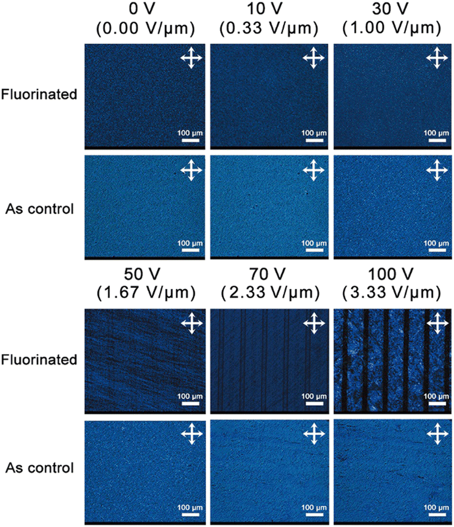 | ||
| Fig. 2 POM images of horizontally aligned fluorinated CLCP coating with a thickness of 5 μm at 50 °C under an applied DC field of different voltages (3 cm × 3 cm ITO electrode substrate: gap, 30 μm; interval, 60 μm). Similar fluorine-free CLCP used as a control. | ||
In order not to limit the newly generated surface topography, we adopted a plate interdigitated electrode, instead of common upper and lower twin electrodes as the driving source. As long as the inner molecular alignment transition is sufficiently great, macroscopic deformation of the fluorinated CLCP coating will also take place under one-side electric actuation. In Fig. 3A, there is a flat surface (roughness coefficient (Ra): 0.0383) on the crude fluorinated CLCP coating with a thickness of 5 μm. Once the DC electric field of 100 V (E = 3.33 V μm−1) was applied, many linear embossments visibly extruded, just like the surface structure of a wheat leaf (see Fig. 3B). Furthermore, it was found that these strip embossments were saddle-like shapes with the width of about 30 μm and the height of over 500 nm (Ra = 0.491; see Fig. 3C). Here, the deformation index (DI) is defined as the quotient of the maximum embossment height divided by the initial coating thickness according to eqn (2).
 | (2) |
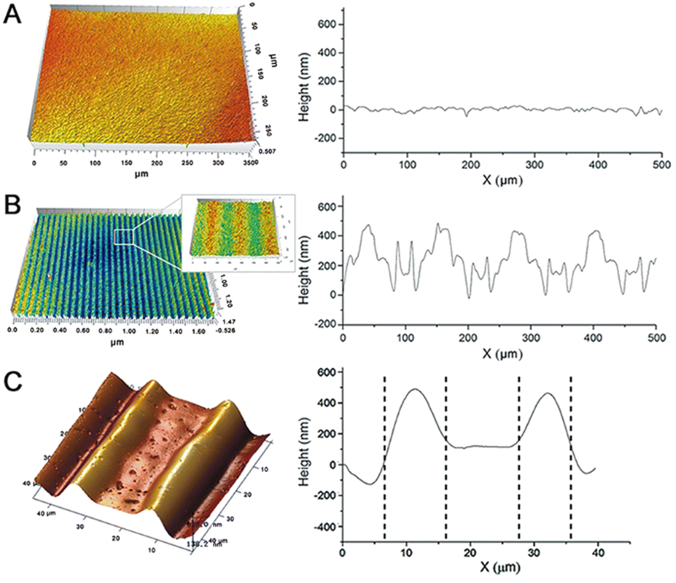 | ||
| Fig. 3 Surface topographies and corresponding cross section curves of horizontally aligned fluorinated CLCP coating with a thickness of 5 μm at 50 °C under an applied DC electric field of 100 V (E = 3.33 V μm−1): 3D profiles before (A) and after electric actuation (B); AFM image after electric actuation (C). (3 cm × 3 cm ITO electrode substrate: gap, 30 μm; interval, 30 μm). | ||
It is known that macroscopic deformation inevitably derives from inner microscopic variation in molecular conformation, arrangement, interaction and so on.41 In voltage-on state, LC molecules with high μ value tilt out of their initial directions along the induced electric potential field. As shown in Fig. 4, these nonuniform electric potential distributions between adjacent strip electrodes will render LC molecules to be reorientated and reduce their order parameter.42–44 A very keen competition exists between the orientation produced by the surface anchoring and by the electric field effects.32 Meanwhile, it will be further enhanced by the limitation of a cross-linking network and a steric hindrance effect throughout the rearrangement of LC units. All of them greatly favor growing free volumes of actuated LC units to macroscopic swelling in the z-axis direction under the strong electric field. In fact, the 30 μm gap is much wider than the other reported electrodes.42 So the actual electric potential field is weakened to create saddle-shaped embossments along the newly generated equipotential lines in Fig. 4B.
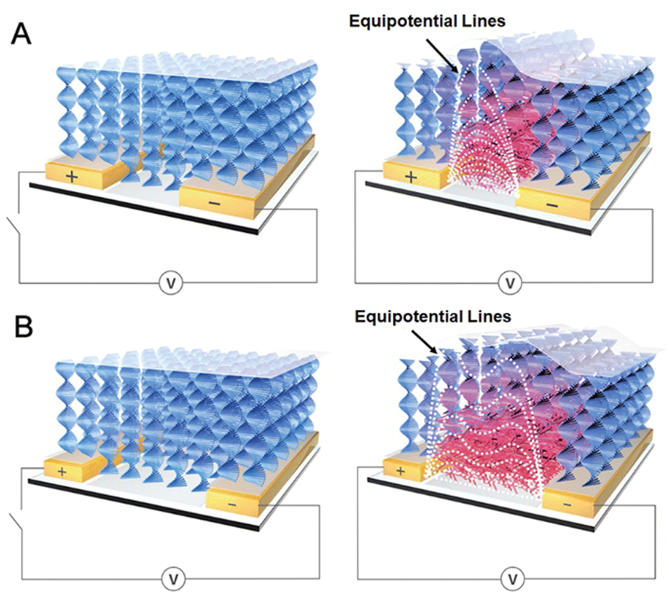 | ||
| Fig. 4 Internal responding mechanism of horizontally aligned fluorinated CLCP coating above the transparent interdigitated comb-shape ITO electrode under an applied DC electric field: ideal (A) and actual model (B). | ||
Besides the above horizontally aligned samples, we also checked the vertically aligned sample. Rubbing angle effect43 suggests that the higher surface rubbing angle between electrical equipotential lines and LC molecules (Φ) induces the higher pretilt angle of LC molecules. In Fig. S18, (ESI†) the vertically aligned CLCP coating with a thickness of 15 μm was continuous and smooth with a fluctuation lower than 100 nm under the same conditions. This response is much weaker than similar horizontally aligned samples (see Fig. S12, ESI†), because the vertically aligned LC molecule units’ Φ is much less than the horizontally aligned ones. Obviously, the latter can twist more with a higher pretilt angle and generate larger swelling in such an electric field to form a specific surface topography.
Moreover, we also tried to actuate surface embossments of the fluorinated CLCP coating by the AC electric field. Only at 50 °C under an applied AC electric field of 100 V (E = 3.33 V μm−1) and 100 kHz, many obvious fluctuations with the height of about 140 nm (DI ≈ 2.8%) on this coating were observed (see Fig. S19, ESI†). This could be attributed to positive and high Δε and initial horizontal alignment.33,45
As expected, the fluorinated CLCP coating with the wheat leaf-like surface topography also changes the surface properties.23 As shown in Fig. 5A and B, the mean of static water contact angle (WCA) on the horizontal coating surface increased from 82.8° to 94.5° after the external electric field was applied. It is important to note that the used ultrapure water droplet lacks finite conductivity and does not contact with any electrode during the contact angle and following tests. Herein, the fluorinated CLCP coating could serve as a dielectric layer, but there is no way to form a parallel resistor (for the electrode) and a capacitor (for the droplet) like an electrowetting-on-dielectric configuration.46 Therefore, unlike the reported works based on electrowetting-based droplet manipulation,13,14 there is no electric double layer emerging at the insulator–droplet interface for reducing the contract angle, and only the patterned embossments make the surface more hydrophobic. This hydrophilic-to-hydrophobic transition based on the Wenzel model essentially decreased the surface adhesion and rendered the direction of droplet motion. It is more critical than the WCA variation value (11.7°) for droplet manipulation.
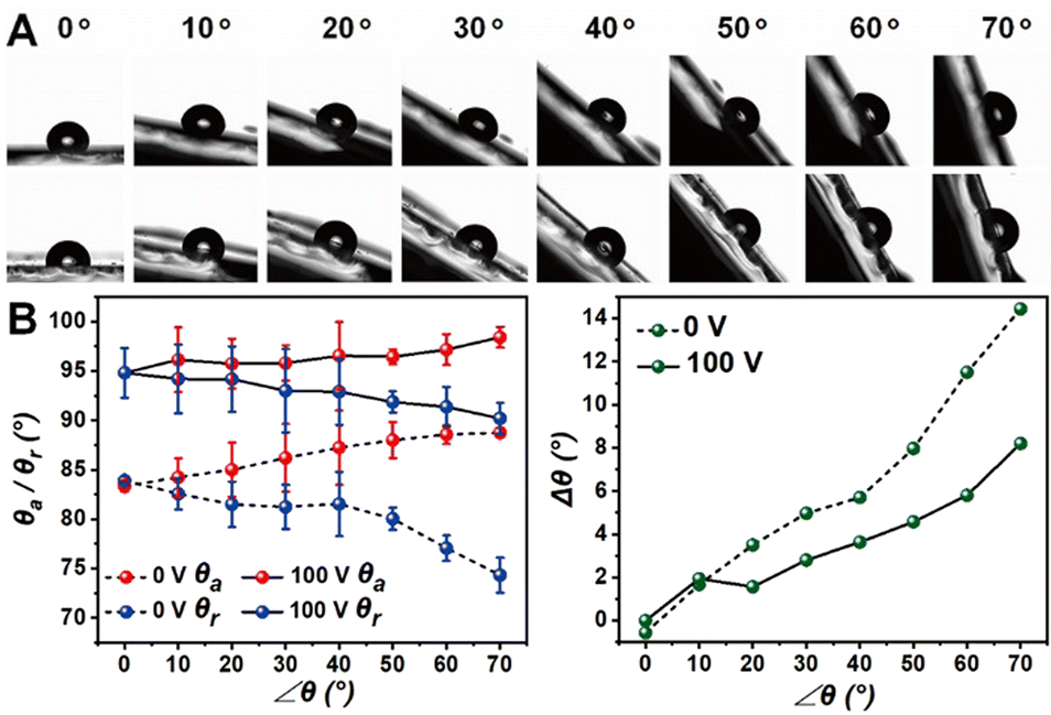 | ||
| Fig. 5 Static water contact angles of the horizontally aligned fluorinated CLCP coating with a thickness of 5 μm before and after DC electric actuation (50 °C; 100 V, E = 3.33 V μm−1) at different inclination angles (A) and corresponding curves (B). (3 cm × 3 cm ITO electrode substrate: gap, 30 μm; interval, 30 μm). Notes: θa, advancing contact angle; θr, receding contact angle; ∠θ, inclination angle; Δθ, contact angle hysteresis. | ||
In particular along with the increase in inclination angle (∠θ), the actuated coating exhibited weakened WCA hysteresis (Δθ, namely the difference value between advancing (θa) and receding WCA (θr)). As ∠θ = 70°, Δθ of the unactuated sample reached 14.4° and the one of the actuated samples only reached 8.2°. Obviously, this small Δθ will definitely be beneficial to droplet rolling in directional droplet manipulation (e.g. droplet motion and condensation).47
These electric field-triggered wettability changes can be illustrated by the following dynamic force analysis (see Fig. 6). Basically, a water droplet that hangs on the vertical fluorinated CLCP surface will be generally subjected to four forces, namely the adhesion force (Fad), the vertically downward gravity (G), and the surface tensions in the lower and upper locations of the droplet (γ and γ′), respectively. Here, both the side effect of air flow and ambient temperature are negligible at a room temperature.48,49 When the water droplet keeps static, all the bearing forces reach a balance. Once the voltage is applied, the wheat leaf-like surface topography will emerge due to the deformation of the CLCP coating. As shown in Fig. 5B and 6, both θa and θr on the wall increased above 90°, but Δθ decreased. It also inevitably causes the decrease of the contact area and Fad, especially in the case of the vertical wall (∠θ = 90°). Meanwhile, the resultant force of γ together with γ′ and G would become vertically downward. As a result, the initial force balance in vertical direction will be broken, and therefore, the droplet will fall.
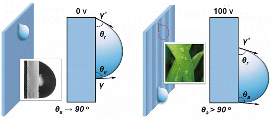 | ||
| Fig. 6 Dynamic force analysis on manipulatable droplet motion above the horizontally aligned fluorinated CLCP coating: unactuated sample without any pattern (left); actuated sample without the wheat leaf-like pattern (right). Notes: θa, advancing contact angle; θr, receding contact angle; γ and γ′, two different surface tensions in the lower and upper locations of a droplet, respectively. | ||
For verifying potential applications, a 13 μL droplet of ultrapure water solidly adhered to the vertically fixed surface of the horizontally aligned fluorinated CLCP coating in a voltage-off state. Once switched to a voltage-on state, the droplet gradually slipped 1.44 centimeters within 18 seconds (0.8 mm s−1; see Fig. 7A and Video S1, S2, ESI†). It is noteworthy that the obtained wheat leaf-like surface also takes on the same function as a wheat leaf. In the wall droplet test, the droplet slipped spontaneously along the longitudinal grooves between these “strips” due to the drainage effect. If the droplet flow direction is perpendicular to the groove direction, these “strips” will block droplet falling, which had been confirmed by the control test.
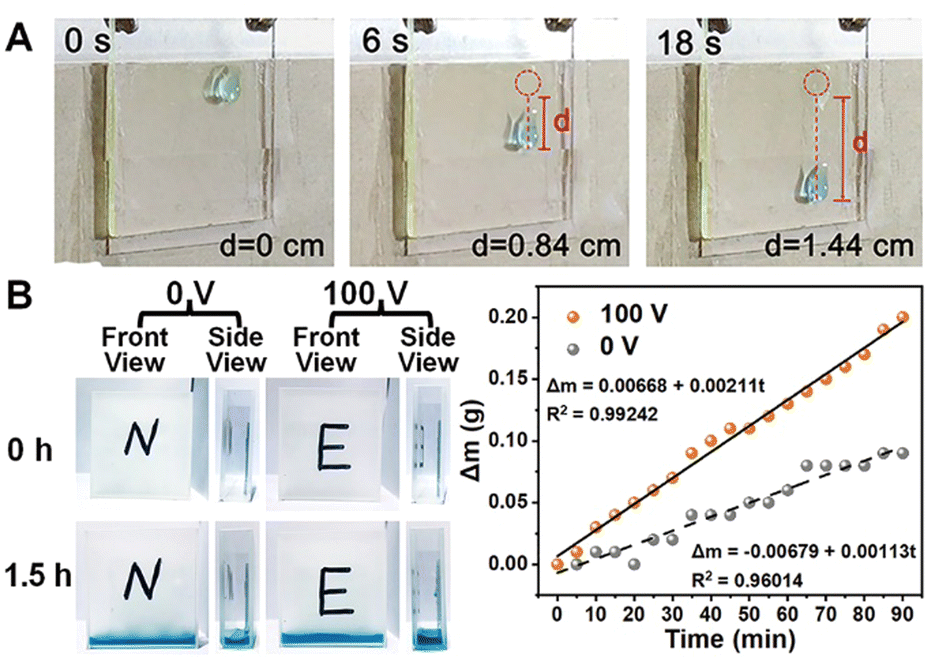 | ||
| Fig. 7 Manipulatable droplet motion and condensation on the surface of the horizontally aligned fluorinated CLCP coating with a thickness of 5 μm: real-time photographs of a droplet on the wall after DC electric actuation (50 °C; 100 V, E = 3.33 V μm−1) (A); object picture of droplet condensation test (left, B) and corresponding mass curves (right, B). (3 cm × 3 cm ITO electrode substrate: gap, 30 μm; interval, 30 μm). Notes: d, slipping distance; Δm, mass increment; in the left Fig. B, the word “N” and “E” on the surface of the cuvette, represent the unactuated and actuated samples, respectively. | ||
Furthermore, two cuvettes internally sticked with CLCP coating were placed in a 70%RH enclosed and humid space at room temperature. More droplets on the actuated surface were concentrated successfully with the condensation rate per unit area of 140.667 g h−1 m−2, in which runs almost twice as fast (see Fig. 7B). This also benefits from the weakened WCA hysteresis by electric actuation.47
Accordingly, other surface properties such as transmittance caused by deformation of the surface topography have also been investigated. The transmittance maximum decreased up to 9% on the patterned surface (see Fig. S21, ESI†), resulting from the enhanced diffuse reflection, which also brings this smart surface with more potential applications.
Conclusions
In summary, a novel DC electric field-driven solid coating with the lowest electric field-responsive threshold so far was constructed for the first time. Under one-side DC electric actuation, many visible and arrayed strip embossments emerged above the solid coating like the surface topography of a wheat leaf. These strips turned the coating surface from hydrophilic to hydrophobic, to successfully trigger droplet motion in the vertical direction. A facile and practical strategy of precise and low-energy directional droplet manipulation on the solid surface was presented, which has potential for application in self-cleaning, microfluidics, catchment from air, and other smart devices.Author contributions
Deyan Li completed most of the experiments; Zhijian Mai wrote the final manuscript; Yancong Feng provided the theoretical calculation and analyses, and helped in analyzing the data; Hui Min prepared the CLCP coating; Jinglun Liao synthesized the two monomers; Yao Wang helped in improving this proposal and revising the paper; Hao Li conceived and designed the whole experiments; Guofu Zhou provided financial support for this project. All authors critically reviewed the manuscript.Conflicts of interest
There are no conflicts to declare.Acknowledgements
This work was financially supported by the National Natural Science Foundation of China (No. 51973070), Guangdong Basic and Applied Basic Research Foundation (No. 2022A1515010577), Science and Technology Program of Guangzhou (No. 2019050001 and 202102020400), Guangdong Provincial Key Laboratory of Optical Information Materials and Technology (No. 2017B030301007), MOE International Laboratory for Optical Information Technologies, Innovative Team Project of Education Bureau of Guangdong Province, Startup Foundation from SCNU and the 111 Project. The calculations were performed at the Shanxi Supercomputing Center of China (TianHe-2).Notes and references
- X. Hou, Design, Fabrication, Properties and Applications of Smart and Advanced Materials, CRC Press, 2016 Search PubMed.
- Y. Cui, D. Li and H. Bai, Ind. Eng. Chem. Res., 2017, 56, 4887–4897 CrossRef CAS.
- G. Huang, M. Li, Q. Yang, Y. Li, H. Liu, H. Yang and F. Xu, ACS Appl. Mater. Interfaces, 2017, 9, 1155–1166 CrossRef CAS.
- W. Xu, H. Zheng, Y. Liu, X. Zhou, C. Zhang, Y. Song, X. Deng, M. Leung, Z. Yang, R. X. Xu, Z. L. Wang, X. C. Zeng and Z. Wang, Nature, 2020, 578, 392–396 CrossRef CAS PubMed.
- C. Yang and G. Li, Sci. Rep., 2017, 7, 15705 CrossRef PubMed.
- S. Ben, T. Zhou, H. Ma, J. Yao, Y. Ning, D. Tian, K. Liu and L. Jiang, Adv. Sci., 2019, 6, 1900834 CrossRef PubMed.
- P. Irajizad, S. Ray, N. Farokhnia, M. Hasnain, S. Baldelli and H. Ghasemi, Adv. Mater. Interfaces, 2017, 4, 1700009 CrossRef.
- C. Li, C. Yu, D. Hao, L. Wu, Z. Dong and L. Jiang, Adv. Funct. Mater., 2018, 28, 1707490 CrossRef.
- H. Zhang, Y. Liu, M. Hua and G. N. Dong, Adv. Eng. Mater., 2019, 21, 014017 Search PubMed.
- J. T. Luo, N. R. Geraldi, J. H. Guan, G. McHale, G. G. Wells and Y. Q. Fu, Phys. Rev. Appl., 2017, 7, 014017 CrossRef.
- M. H. Biroun, M. T. Rahmati, M. Jangi, R. Tao, B. X. Chen and Y. Q. Fu, Sens. Actuators, A, 2019, 299, 111624 CrossRef CAS.
- Y. Zhang and G. Wittstock, Small, 2017, 13, 1601691 CrossRef PubMed.
- Y. Yan, Z. Guo, X. Zhang, L. He, Y. Li, K. Liu, J. Cai, D. Tian and L. Jiang, Adv. Funct. Mater., 2018, 28, 1800775 CrossRef.
- A. D. Ruvalcaba-Cardenas, P. Thurgood, S. Chen, K. Khoshmanesh and F. J. Tovar-Lopez, ACS Appl. Mater. Interfaces, 2019, 11, 39283–39291 CrossRef CAS PubMed.
- H. Dai, C. Gao, J. Sun, C. Li, N. Li, L. Wu, Z. Dong and L. Jiang, Adv. Mater., 2019, 31, e1905449 CrossRef PubMed.
- Q. Sun, D. Wang, Y. Li, J. Zhang, S. Ye, J. Cui, L. Chen, Z. Wang, H. J. Butt, D. Vollmer and X. Deng, Nat. Mater., 2019, 18, 936–941 CrossRef CAS PubMed.
- C. Liu, J. Sun, J. Li, C. Xiang, L. Che, Z. Wang and X. Zhou, Sci. Rep., 2017, 7, 7552 CrossRef PubMed.
- Y. L. Han, M. Li, Q. Yang, G. Huang, H. Liu, Y. Qin, G. M. Genin, F. Li, T. J. Lu and F. Xu, Adv. Funct. Mater., 2017, 27, 1606607 CrossRef.
- P. Li, B. Zhang, H. Zhao, L. Zhang, Z. Wang, X. Xu, T. Fu, X. Wang, Y. Hou, Y. Fan and L. Wang, Langmuir, 2018, 34, 12482–12487 CrossRef CAS PubMed.
- Z. Zhang, X. Guo, H. Tang, J. Ding, Y. G. Zheng and S. Li, ACS Appl. Mater. Interfaces, 2019, 11, 28562–28570 CrossRef CAS PubMed.
- S. Deng, W. Shang, S. Feng, S. Zhu, Y. Xing, D. Li, Y. Hou and Y. Zheng, Sci. Rep., 2017, 7, 45687 CrossRef CAS PubMed.
- J. S. Lee, J. Y. Moon and J. S. Lee, Appl. Therm. Eng., 2014, 72, 104–113 CrossRef.
- C. Neinhuis and W. Barthlott, Ann. Bot., 1997, 79, 667–677 CrossRef.
- J. A. Lv, Y. Liu, J. Wei, E. Chen, L. Qin and Y. Yu, Nature, 2016, 537, 179–184 CrossRef CAS PubMed.
- Z.-H. Jia, M.-Y. Chen and H.-T. Zhu, Appl. Phys. Lett., 2017, 110, 091603 CrossRef.
- G. Babakhanova, T. Turiv, Y. Guo, M. Hendrikx, Q. H. Wei, A. Schenning, D. J. Broer and O. D. Lavrentovich, Nat. Commun., 2018, 9, 456 CrossRef PubMed.
- H. M. van der Kooij, S. A. Semerdzhiev, J. Buijs, D. J. Broer, D. Liu and J. Sprakel, Nat. Commun., 2019, 10, 3501 CrossRef.
- A. A. Shah, H. Kang, K. L. Kohlstedt, K. H. Ahn, S. C. Glotzer, C. W. Monroe and M. J. Solomon, Small, 2012, 8, 1551–1562 CrossRef CAS PubMed.
- D. Liu, N. B. Tito and D. J. Broer, Nat. Commun., 2017, 8, 1526 CrossRef PubMed.
- F. L. L. Visschers, H. Gojzewski, G. J. Vancso, D. J. Broer and D. Liu, Adv. Mater. Interfaces, 2019, 6, 1901292 CrossRef.
- W. Feng, D. J. Broer and D. Liu, Adv. Mater., 2018, 30, 1704970 CrossRef PubMed.
- J. Leyte and P. Van Woerkom, Appl. Spectrosc., 1997, 51, 1711–1714 CrossRef CAS.
- M.-H. Wu, K. i Koseki and T. Amari, Thin Solid Films, 2003, 438, 396–402 CrossRef.
- M. Trau, D. A. Saville and I. A. Aksay, Science, 1996, 272, 706–709 CrossRef CAS PubMed.
- T. Gong, D. T. Wu and D. W. M. Marr, Langmuir, 2002, 18, 10064–10067 CrossRef CAS.
- P. Lv, Y. You, J. Li, Y. Zhang, D. J. Broer, J. Chen, G. Zhou, W. Zhao and D. Liu, Adv. Sci., 2021, 2004749 CrossRef CAS PubMed.
- D. M. Larruskain, I. Zamora, O. Abarrategui and Z. Aginako, Electr. Pow. Syst. Res., 2011, 81, 1341–1348 CrossRef.
- P. Kirsch, J. Fluorine Chem., 2015, 177, 29–36 CrossRef CAS.
- M. Portugall, H. Ringsdorf and R. Zentel, Makromol. Chem., 1982, 183, 2311–2321 CrossRef CAS.
- J.-H. Liu, Y.-K. Wang, C.-C. Chen, P.-C. Yang, F.-M. Hsieh and Y.-H. Chiu, Polymer, 2008, 49, 3938–3949 CrossRef CAS.
- H. Chung, J. Choi, J. H. Yun and M. Cho, Sci. Rep., 2016, 6, 20026 CrossRef CAS.
- C. J. Chen, J. Appl. Phys., 2000, 87, 5–9 CrossRef CAS.
- Z. Ge, X. Zhu, R. Lu, T. X. Wu and S.-T. Wu, Appl. Phys. Lett., 2007, 90, 221111 CrossRef.
- L.-L. Tian, F. Chu, H. Dou, L. Li and Q.-H. Wang, Crystals, 2019, 9, 431 CrossRef CAS.
- L. E. Aguirre, E. Anoardo, N. Eber and A. Buka, Phys. Rev. E: Stat., Nonlinear, Soft Matter Phys., 2012, 85, 041703 CrossRef PubMed.
- W. C. Nelson and C. C. Kim, J. Adhes. Sci. Technol., 2012, 26, 1747–1771 CrossRef CAS.
- D. Baratian, R. Dey, H. Hoek, D. Ende and F. Mugele, Phys. Rev. Lett., 2018, 120, 214502 CrossRef CAS PubMed.
- C. Antonini, F. J. Carmona, E. Pierce, M. Marengo and A. Amirfazli, Langmuir, 2009, 25, 6143–6154 CrossRef CAS PubMed.
- B. S. Yilbas, A. Al-Sharafi, H. Ali and N. Al-Aqeeli, RSC Adv., 2017, 7, 48806–48818 RSC.
Footnotes |
| † Electronic supplementary information (ESI) available: Chemical compositions of fluorine-free CLCP coating, 1H-NMR spectra, 13C-NMR spectra, and mass spectra of two monomers, DSC curves and corresponding POM images of two monomers, DSC curves of the fluorinated LC mixture and the horizontally aligned CLCP coatings, 3D surface topography and corresponding cross section curve of the horizontally aligned CLCP coating without predetermined heating treatment, cross section curves of the horizontally aligned CLCP coating with a thickness of 15 and 35 μm, 3D surface topographies (interval: 60 and 120 μm) of the horizontally aligned CLCP coating, 3D surface topographies of the horizontally and vertically aligned fluorine-free CLCP coatings, 3D surface topography of the vertically aligned fluorinated CLCP coating, AC electric field-responsive capabilities of the horizontally aligned fluorinated CLCP coating at 50 °C and 100 V (100 kHz), the droplet condensation test of the horizontally aligned fluorinated CLCP coating at 50 °C and 100 V, transmittance curves of the horizontally aligned fluorinated CLCP coating, comparison table of the electric field-responsive capabilities of the reported LC systems, and videos on the wall droplet test of the horizontally aligned fluorinated CLCP coating at 50 °C and 100 V. See DOI: https://doi.org/10.1039/d2ma00796g |
| ‡ Deyan Li, Zhijian Mai and Yancong Feng contributed equally to this work. |
| This journal is © The Royal Society of Chemistry 2022 |