
 Open Access Article
 This Open Access Article is licensed under a
 Creative Commons Attribution 3.0 Unported Licence
Self-assembly of PBTTT–C14 thin films in supercritical fluids†
Nastaran
Yousefi
a,
Richard D.
Pettipas
b,
Timothy L.
Kelly
 b and
Loren G.
Kaake
*a
b and
Loren G.
Kaake
*a
aDepartment of Chemistry, Simon Fraser University, 8888 University Dr, Burnaby, BC V5A 1S6, Canada. E-mail: lkaake@sfu.ca
bDepartment of Chemistry, University of Saskatchewan, 110 Science Place, Saskatoon, SK S7N 5C9, Canada
First published on 7th February 2022
Abstract
In order to develop more atom-economical deposition methods for polymer semiconductors, we investigated physical supercritical fluid deposition (p-SFD) to form thin films of a popular bithiophene semiconducting polymer (PBTTT). We deposited thin films of PBTTT–C14 on a substrate without the need for in situ chemical reactions. Depositions were performed in n-pentane at several pressures above the critical pressure of the pure liquid. The resulting films were studied with atomic force microscopy (AFM) and grazing incidence wide angle X-ray scattering (GIWAXS). At lower pressures, nanowire morphologies were observed and correlated with a more gradual decrease in the isobaric saturation solubility with respect to temperature. The isotropic distribution of crystallite textures suggests that the wires are formed in solution prior to deposition. The addition of 0.5% mol ratio of toluene also had a strong influence on thin film morphologies. Nanowires were observed at higher pressures in the presence of toluene, which we correlated with increasing saturation solubility with respect to pressure. Taken in sum, the results illustrate the profound influence of subtle changes in polymer solubility on the self-assembly process.
1. Introduction
The combination of mechanical flexibility and electronic functionality offer the promise of flexible and conformal electronics for a number of applications including organic field-effect transistors (OFETs),1–3 organic light emitting diodes (OLEDs),4,5 organic photovoltaics cells (OPVs),6,7 radio-frequency identification (RFID) tags,8 sensors,9 wearable technologies,10,11 and medical devices.12 The ability of organic electronic materials to be first synthesized and then deposited leverages both the benefits of synthetic organic chemistry and materials science. An immense variety of polymers can potentially be synthesized, and a suite of well-known tools allow them to be accurately characterized. This allows materials deposition techniques to be developed and optimized independently.Widespread commercial application of polymer semiconductors requires ecofriendly synthesis and thin film deposition techniques.13,14 The introduction of direct heteroarylation polymerization has allowed a move away from Stille coupling and its toxic metal reagents and waste products.15 In a related direction, organic semiconductors that can be processed in toluene, alcohols or even water are being developed in the general move away from halogenated solvent processing.16,17
In comparison, small molecule organic semiconductors can be deposited from the vapor phase, eliminating the need for solvents altogether.18 However, this limits the chemical design space of potential compounds, especially in terms of their molecular weight. Indeed, polymers and high molecular weight oligomers often cannot be sublimated without causing chemical degradation. Many of the highest performing organic semiconductors are high molecular weight materials that cannot take advantage of the scalable and reproducible technique of vapor deposition. As such, there is an opportunity for the development of a deposition technique that works with high molecular weight materials while conferring the benefits of physical vapor deposition.
Ideally, a deposition process provides films that are homogeneous over a large area both in terms of film thickness and morphology. Examples of solution-based deposition techniques are coating (spin-coating,19 spray-coating,20,21 doctor blade coating),22,23 drop-casting,24,25 Langmuir–Blodgett,26,27 and printing (inkjet,28 gravure,29 reverse-offset30). Printing techniques are common due to their roll-to-roll compatibility and ability to print on flexible substrates.31 However, each technique offers trade-offs in terms of scalability, ease of ink formulation, ultimate resolution, and use with substrates of non-trivial curvature.
We are developing a deposition method for high molecular weight materials that relies on the unique solvation properties of supercritical fluids, called physical supercritical fluid deposition (p-SFD).32 The technique is designed to maintain the benefits of vapor phase processing and has the additional benefit of not requiring line of sight access to the surface where film formation takes place. When a solvent is at a temperature well below its critical temperature, the saturation concentration of a solid solute typically increases with temperature irrespective of the pressure. However, as a solvent is heated towards its critical temperature, the solvent begins to transition continuously from liquid-like to gas-like behavior when the pressure exceeds the critical pressure. As this occurs, the saturation solubility reaches a maximum, and then decreases with increasing temperature, eventually approaching zero in the limit of pure gas-like behavior. By holding the bulk solvent at the solubility maximum and heating a substrate already in the vessel, thin polymer films can be precipitated from supercritical solvents. By controlling the local temperature on a substrate, the deposition process can be directed, achieving linewidths of 5 microns, several times better than aerosol jet printing methods.32
From an ecofriendly perspective, p-SFD has several benefits. Firstly, the process is highly atom-economical. Following deposition, the contents of the pressure vessel are exhausted to a collection vessel, condensing the solvent, and collecting unused deposition material. This process generates minimal chemical waste. Secondly, the process opens the possibility of using carbon dioxide as a solvent, which could be extracted from the atmosphere. However, in order for this technique to be useful in making organic optoelectronic devices, we must be able to control the self-assembly processes that give rise to high performance thin film morphologies.
Current strategies for controlling polymer semiconductor thin film morphology include thermal annealing,33,34 solvent engineering by addition of an antisolvent or cosolvent,35–42 solvent vapor annealing,43–45 and post formation alignment via mechanical stretching or high-temperature rubbing.46,47 Amongst all these approaches, the use of solvent additives has been widely explored for fabrication of high-performance electronic devices.36,37,48,49
Supercritical fluids have also been used as a post processing step for polymer morphology optimization. For example, supercritical fluids (SCFs) were used in the processing of OPVs50,51 OFETs,52 and hole-only diodes.53 In addition, they have been used to modify the morphology of aliphatic polymer films,54–58 including polymer/polymer blends.59 In these studies, the general trend is that post-treatment with supercritical fluids promotes chain mobility, resulting in increased crystallinity, dewetting, or vertical phase separation. This approach contrasts with ours in that supercritical fluids are used to modify the morphology of films that were formed by some other process, where we are forming films directly under supercritical conditions. Previous studies from our lab on isotactic polypropylene suggests that pressure and solvent additive can exert a profound influence on the thin film morphology.60,61 While we have formed semiconducting polymer films in our previous work using p-SFD, this study represents the first detailed examination of semiconducting polymer thin film morphologies formed using this process.
Here, we investigate the effect of solvent additives and pressure on the morphology of PBTTT-C14 thin films processed in supercritical n-pentane: toluene using atomic force microscopy (AFM), helium ion microscopy (HIM), and grazing incidence wide angle X-ray scattering (GIWAXS). The AFM results demonstrate a stark contrast between films formed via p-SFD at different pressures. Specifically, changing the pressure of the fluid influences viscosity and the solubility behavior, both of which can influence thin film morphology. We observed nanowire formation and a smoother thin film morphology with more isotropic texturing in response to a steeper solubility decline with respect to temperature. The addition of toluene to the system resulted in nanowire formation at higher pressures due to higher solution viscosity. Based on our findings, the morphology of the films processed by p-SFD technique adopt smoother and more ordered films with increasing the solution viscosity and are also influenced by subtle changes in polymer solubility with temperature. Managing these variables will allow films with good performance to be grown using this atom-economical deposition technique.
2. Results and discussion
The pressure chamber used for investigating the polymer solubility and thin film formation was a custom-made vessel, fabricated from a solid block of beryllium copper (see Fig. S1, ESI†). The chamber can be pressurized and heated by means of a manual pressure generator and cartridge heaters. The front and back of the chamber is fitted with sapphire windows to allow for in situ transmission UV-vis measurements of the solution.Understanding the conditions required for thin film deposition requires an understanding of the saturation solubility behavior of the solvent/polymer system. To investigate the polymer solubility, a small glass crucible was filled with poly[2,5-bis(3-tetradecylthiophen-2-yl)thieno[3,2-b]thiophene] (PBTTT–C14), capped with glass wool, and placed at the bottom of the chamber. The chamber was then filled to the point of overflowing with deoxygenated n-pentane or a n-pentane: toluene (0.5% mol) solution. UV-vis spectra of the chamber and its contents were collected approximately 15 minutes after the chamber temperature had stabilized to ensure the solution had come to its saturation concentration. The blank spectrum used in the calculation of absorbance was collected at room temperature. Blank spectra were collected at each pressure, as subtle changes to cell transmission occur, presumably through variations in the real index of refraction with respect to pressure. Fig. 1a shows absorbance spectra collected at 7.0 MPa as a function of temperature for PBTTT–C14 in a pure n-pentane solution. Because of the high absorbance values involved, the resolution of the spectrometer was decreased, and the spectra were fitted with two Gaussian peaks to capture the behavior accurately.
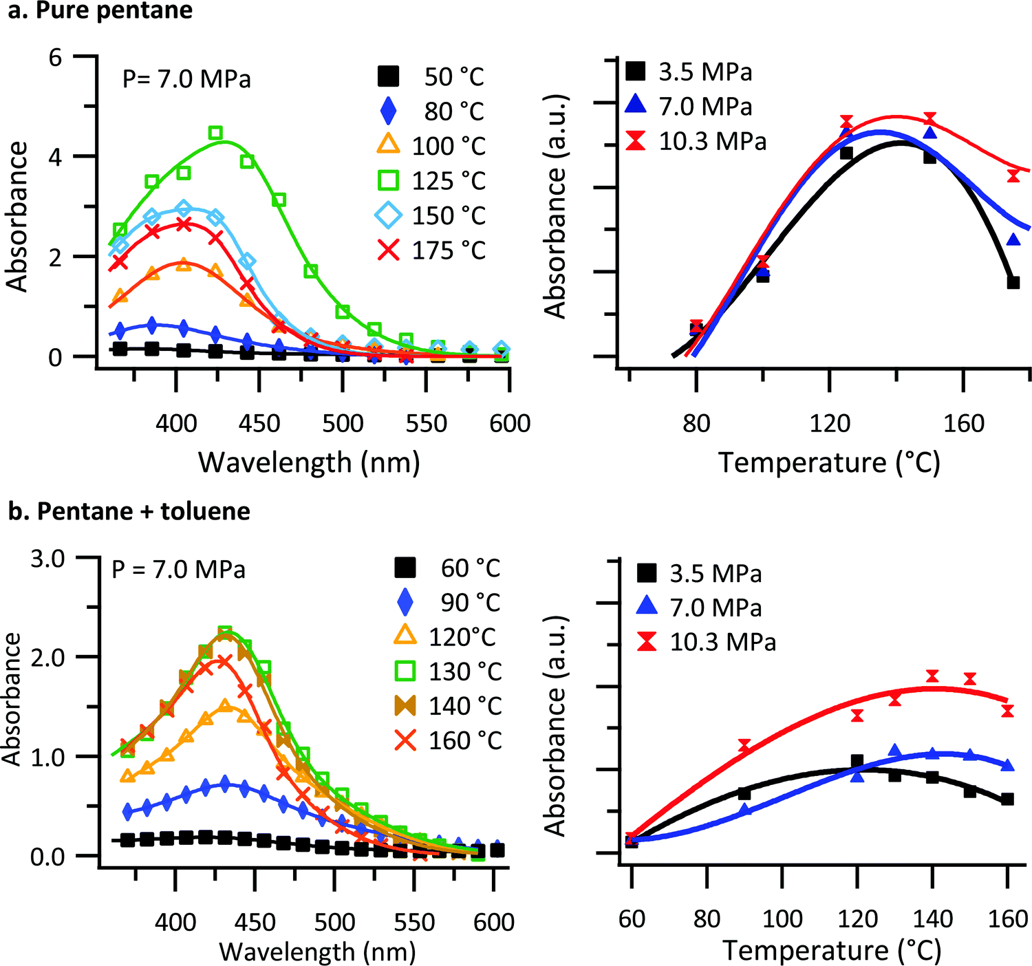 | ||
| Fig. 1 In situ UV-vis transmission results of PBTTT–C14 in (a) pure n-pentane and (b) n-pentane: toluene (0.5% mol) solution. UV-vis spectral measurements for the chamber and its contents (solution) for several temperatures and a single pressure (left) and the integrated UV-vis absorbance as a function of temperature for several pressures (right). Solid lines indicate the fit to the data using eqn (1). | ||
As shown in Fig. 1a, there is an increase in absorbance for temperatures up to 125 °C. With further increases in temperature, the absorbance decreases. Similarly, there is an increase in absorbance for temperatures up to 130 °C in the case of n-pentane: toluene, Fig. 1b, and with further increase in temperature, the absorbance decreases. We interpret the absorbance as being reflective of the concentration of PBTTT–C14 in solution. Non-monotonic solubility behavior as a function of temperature was observed for both PBTTT–C14 and isotactic polypropylene in pure n-pentane previously.32,61 Additionally, the overall absorbance as a function of temperature for different pressures are displayed in Fig. 1 (right panel) using the total integrated intensity obtained from a fit of the data. Based on the observations, the overall absorbance does not change significantly as a function of pressure in pure n-pentane. However, there is a small but noticeable pressure dependence in the solubility at the highest temperatures. When toluene is added to the system the effect of pressure becomes more pronounced. In the presence of toluene, the increase in the solubility of PBTTT–C14 as a function of pressure reflects a negative value for the volume change of mixing (ΔVm).
As shown in Fig. 1b, the non-monotonic solubility behavior as a function of temperature is observed for all the pressures studied. To confirm this interpretation, gravimetric analysis was carried out simultaneously to establish the PBTTT–C14 solubility as a function of temperature. Fig. S2 (ESI†) shows both the results from the gravimetric analysis and in situ UV-vis transmission of chamber and its contents (solution) for several temperatures and a single pressure (7.0 MPa). The data gathered via gravimetric analysis are in good agreement with the results from in situ UV-vis transmission results, confirming an increase in the saturation solubility as a function of temperature below 130 °C and decreasing saturation solubility at temperatures above that.
The change in saturation solubility as a function of temperature as extracted from the UV-vis data was fitted. The expression used was developed previously56,57 and describes the concentration of polymer (c) versus temperature:
c = b + a![[thin space (1/6-em)]](https://www.rsc.org/images/entities/char_2009.gif) exp[–γ(T – T0)2/RT]. exp[–γ(T – T0)2/RT]. | (1) |
In eqn (1) describes the temperature of the solubility maximum using the enthalpy of solvation (ΔH) and the slope of solvent entropy with respect to temperature (ΔSsolvent ∝ γT). The fitting results help to highlight the changes in the solubility behavior with respect to pressure. In the presence of toluene, the solubility increases and T0 shifts towards higher temperature with increasing pressure. The increase in T0 is likely due to a decrease in γ as toluene is a better solvent, with a less positive ΔH in comparison with pentane. The increasing solubility with increasing pressure is related to the volume change of mixing (ΔVm). Negative values of ΔVm are typically associated with increasing solubility with increasing pressure. Microscopically, we attribute the negative value of ΔVm to the formation of a dense solvent shell rich in toluene.
The nonmonotonic solubility behavior of PBTTT–C14 is the vital to the process of p-SFD, allowing polymer films to be grown in situ on a substrate without the need for chemical reactions. To initiate the polymer deposition on a substrate, we hold the temperature of the cell wall at the solubility maximum (Twall ≈ 130 °C) and resistively heat a substrate immersed in the fluid (Tsub ≈ 160 °C). Based on our previous studies, the film thickness increases with respect to time in an approximately linear fashion, which allow us to control film thickness in a relatively straightforward manner.32
To investigate the morphology of the PBTTT–C14 films, a series of films were deposited in situ using p-SFD in pure n-pentane and a mixture of n-pentane: toluene (0.5% mol) at different pressures. AFM images shown in Fig. 2 demonstrate the impact of pressure and solvent additive on film morphology. In pure n-pentane (Fig. 2a), at lowest pressure (3.5 MPa) we observe a fibrillar morphology reminiscent of π-stacked nanowires of poly(3-hexylthiophene).62 As the pressure increases to 7.0 MPa, we observe a more sweeping fibrillar morphology with fibers spanning almost the entire image that resembles the isotropic nanoribbons observed in casted films of PBTTT in previous reports.63,64 As pressure increases further, the length of the fibers decreases, and the morphology becomes more featureless. In the presence of toluene (Fig. 2b), the fibers are more arranged in a broad sweeping manner at lower pressures and exhibit nanowires at the highest pressures. We interpret nanowires as demonstrating crystalline ordering of individual chains through π-stacking with the backbone axis perpendicular to the fiber axis (that is stacking direction). We interpret the broader, sweeping morphologies to indicate an alternative stacking motif, one with the polymer axis being parallel to the fiber axis. In addition, PBTTT–C14 films deposited via p-SFD are markedly different than spin-coated films that exhibit semi-crystalline but otherwise relatively featureless surfaces, similar to the previous reports for spin-coated and unheated PBTTT films (Fig. S5, ESI†).64,65
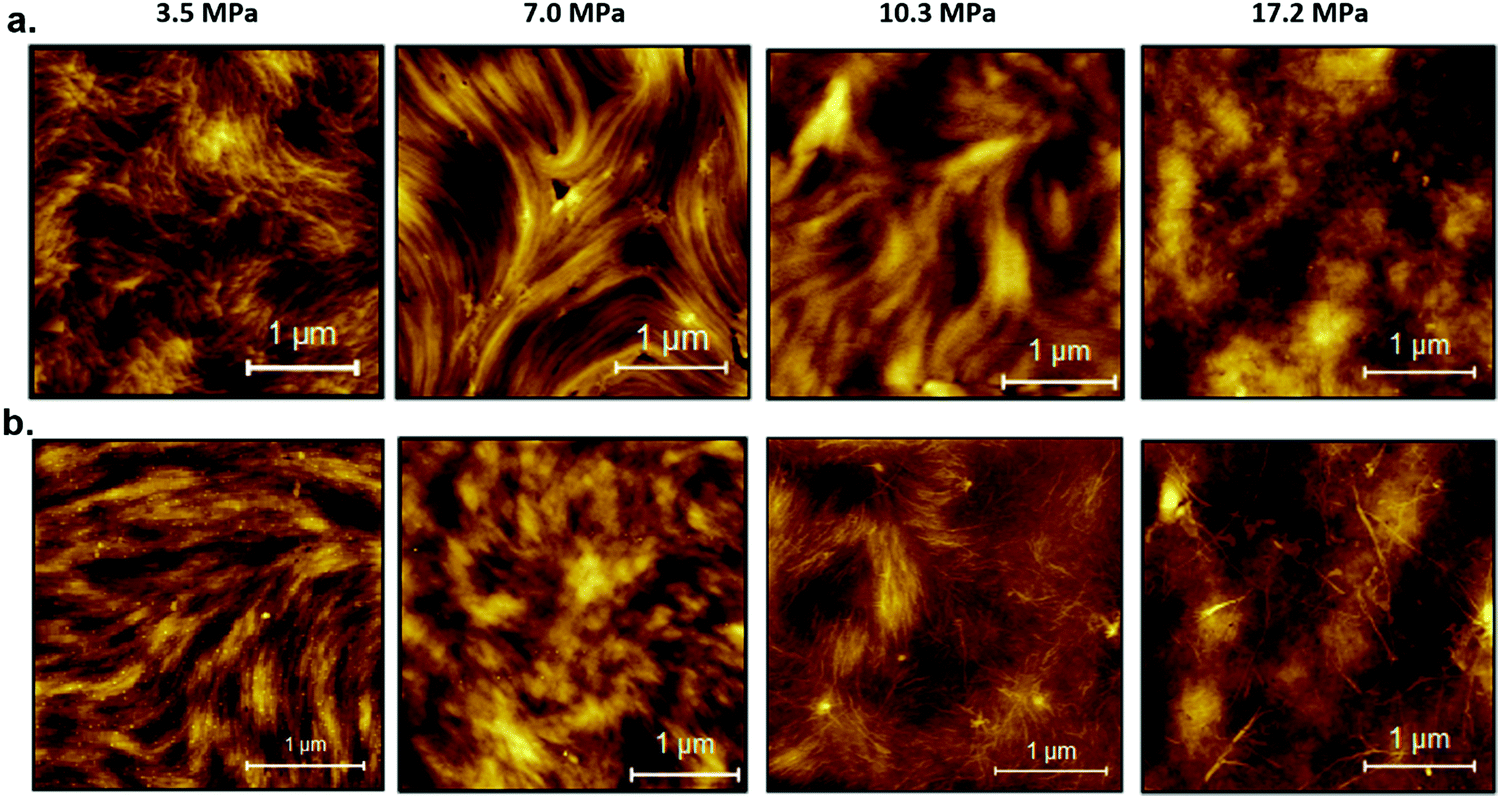 | ||
| Fig. 2 Atomic force microscopy images of PBTTT–C14 films formed in supercritical (a) pure n-pentane and (b) n-pentane: toluene at different pressures. | ||
In order to better understand the film formation process, GIWAXS measurements were carried out. Fig. 3(a) and (b) shows the results, which exhibit d-spacings of 0.29 Å−1 which is comparable to previous measurements of PBTTT–C14 films.66,67 Comparing the GIWAXS measurements of PBTTT–C14 deposited films via p-SFD with those of a spin-coated PBTTT–C14 film (Fig. 3 and Fig. S6, ESI†) does not suggest that the films are of markedly different crystallinity. UV-vis spectra of the spin-coated and p-SFD grown PBTTT–C14 films collected ex situ (Fig. S7, ESI†) suggests that the local ordering is somewhat lower in films processed in supercritical fluids, presumably a reflection of shorter chain correlation lengths as opposed to lower crystallinity.
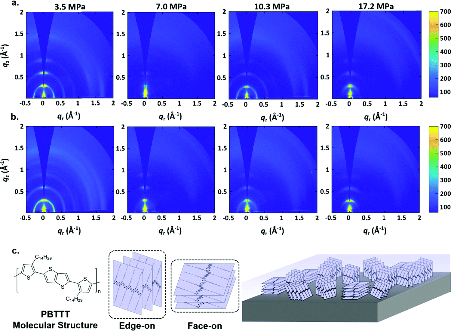 | ||
| Fig. 3 GIWAXS patterns of PBTTT–C14 films grown in (a) n-pentane and (b) n-pentane: toluene at different pressures. (c) The molecular structure of PBTTT–C14 and the drawing illustrating the different molecular orientation of PBTTT–C14 (edge-on and face-on) in thin layers with respect to the substrate surface. | ||
As shown in Fig. 3a, the PBTTT–C14 film at 3.5 MPa pure n-pentane is still highly crystalline, however, they show a more isotropic texture relative to spin-coated films (Fig. S6, ESI†). At higher pressures, the film appears to be more textured, showing a greater population of molecules with edge-on orientation. This is especially true with films deposited at 7.0 MPa, however, the behavior is somewhat subtle and lacks a clear monotonic dependence, making it difficult to reach further conclusions.
Fig. 3b displays the GIWAXS results of PBTTT–C14 films grown n-pentane: toluene at different pressures. In a manner similar to pure n-pentane, the film at 3.5 MPa is highly crystalline, and has a more isotropic texture than the PBTTT–C14 spin-coated film. Texture analysis (Fig. S8, ESI†) confirms what can estimated from the radial scattering patterns; among films formed at different pressures, the films at 7.0 MPa are the most strongly edge-on oriented, with a somewhat lower crystallinity. This observation is also irrespective of the solvent used. Fig. 3c contains the chemical structure of PBTTT–C14 and a drawing illustrating the difference between edge-on and face-on orientations with respect to the substrate.
In order to understand the self-assembly process of PBTTT–C14 in supercritical solvents, we made a comparison with previous studies on isotactic polypropylene, where we hypothesized that deposition occurs in two steps. The first process is a pre-aggregation step that occurs in solution and is triggered by a drop in polymer solubility near the heated substrate surface. Self-assembly processes occurring in this step depend upon the solution properties, in particular the Rayleigh number, which describes the amount of turbulence near the substrate surface. It was found out that increasing solution turbulence is correlated with decreases in polymer crystallinity. In the second step, deposition material contacts the substrate, where it can then move in a process reminiscent of surface diffusion in physical vapor deposition. We discovered that the presence of high boiling point solvent additives can promote ordering in this step.
In Fig. 1a (right panel), we observe very similar saturation concentrations with respect to pressure at the solubility maximum, and so, are forced to conclude that changes in the Rayleigh number with respect to pressure do not drive the changes in sample morphology. However, it was observed that the decrease in solubility with respect to temperature is pressure dependent above the solubility maximum. This suggests that the amount of material precipitating from solution near the substrate is greater at low pressures and at a less at higher pressures. As a result, the amount of material available to form large-scale crystallites in solution is smaller at higher pressures. This hypothesis explains the appearance of nanowires at low pressures where solution phase self-assembly has sufficient material to create nanowire aggregates that are then deposited onto the substrate. Presumably, the larger aggregates would be less capable to diffusing on the substrate, leading to a more uniform large scale thin film morphology characterized by nanowires of isotropic orientation. Isotropic, highly crystalline nanowire formation is supported by our GIWAXS observations. Film uniformity at longer length scales is supported by helium ion microscope images (Fig. S9, ESI†). At higher pressures, the amount of material that can pre-aggregate is limited, inhibiting nanowire growth. These smaller structures can then diffuse on the substrate surface, leading to rougher with more textured crystallinity. The GIWAXS data supports greater texturing at high pressures and helium ion microscope images demonstrate that films exhibit dewetting and enhanced roughness.
In the case of n-pentane: toluene, polymer solubility is strongly pressure dependent. This should accompany a change in Rayleigh number with more viscous flows occurring at higher pressure. The more viscous flow decreases the amount of turbulence, leading to the formation of nanowires at higher pressures. At lower pressures, the formation of large wires is inhibited, presumably because of a shallow decrease in solubility with increasing temperature which results in a lower nucleation density and smaller crystallites. This conclusion is supported by a broadening of the higher order diffraction arcs in n-pentane: toluene relative to pure n-pentane at 3.5 MPa. However, the presence of solvent additives would allow for the motion of polymer chains on the surface once deposited, explaining generally improved film uniformity with the toluene solvent additive.
Taken in sum, this study illustrates that self-assembly in supercritical fluids is a complicated phenomenon with a number of subtle effects that can lead to dramatic changes in sample morphology. In particular, this study highlights the importance of solution viscosity and the magnitude of the decrease in polymer solubility with respect to temperature during the deposition process. Gaining mastery over these effects is paramount to leveraging the full potential of p-SFD as a green processing technique.
3. Conclusion
The development of physical supercritical fluid deposition (p-SFD) as an environmentally friendly means of thin film deposition requires a deep understanding of the relationship between processing and film structure. We studied the self-assembled film structure of PBTTT-C14 grown from n-pentane and n-pentane: toluene solutions. We found that thin film morphologies differ dramatically from spin-coated films and that subtle changes in the isobaric solubility behavior of the polymer exert important influences on the self-assembly process. In particular, we found that nanowire formation in solution is promoted by a steeper decrease in solubility with respect to temperature. This is accompanied by a more isotropic texturing and smoother thin films. In the presence of toluene, nanowire formation is preferred at higher pressures as a result of higher solution viscosity. More broadly, we conclude that smooth, ordered films are more likely to be deposited from viscous solutions with a small change in solubility with respect to temperature.4. Experimental
4.1 Supercritical fluid chamber description
A custom pressure vessel was constructed from a block of beryllium copper (BeCu) with 6 ports surrounding vessel interior. The bottom port serves as a fluid inlet and the top port serves as an outlet. One of the side ports is used to introduce a substrate for thin film deposition. The chamber also possesses a pair of sapphire windows which allow the internal chamber contents to be monitored in situ. The system is pressurized by using a manual pressure pump generator (HiP 62-6-10), and the pressure is monitored with a transducer (Swagelok PTI series). All the constituent parts of the system are rated to greater than 53.0 MPa and are regularly pressure tested to 24.0 MPa. In order to ensure the integrity of the system, there is a 38.0 MPa rupture disc to prevent over-pressurization. The volume of the chamber was kept as small as feasible (≈27 mL) to ensure safety in an academic laboratory setting. Additionally, oxygen was rigorously removed from solvent and the system by purging our solvent with nitrogen and overfilling the vessel. The chamber is also placed in Lexan safety enclosure that is actively ventilated to remove any inadvertently generated solvent vapors.4.2 Solubility measurements of PBTTT–C14
Transmission UV-vis spectroscopic measurements were carried out by placing PBTTT–C14 into a crucible at the bottom of the chamber before the vessel was sealed and filled with solvent. The chamber exterior was heated by an Omega benchtop PID controller (CSi32 Series 0.04 °C temperature stability) used to drive four cartridge heaters connected in parallel and placed symmetrically about the edges of the chamber. After the temperature stabilized, the solution was pressurized to 3.5, 7.0, 10.3, and 17.2 MPa by using the manual pressure generator. The system was given ∼15 min to reach equilibrium before solution absorbance measurements were collected. Transmission UV-vis spectroscopic measurements of the pressure vessel were performed using an Ocean Optics USB4000 spectrometer, which covers 200–1100 nm ranges with a Toshiba TCD1304AP (3648-element linear silicon CCD array) detector. The short-arc xenon discharge lamp (USHIO UXL-75W with 300–1100 nm wavelength range) was used as the light source. A solution of malachite green in water (10−6–10−4 M) was used as a light absorber and placed on the light path before the light reaches the chamber to decrease the light source intensity. The blank absorbance used for the measurements was simply the absorbance of malachite green solution plus the chamber solution at room temperature. A different blank was collected for each pressure to take into account the slight transmission increase with pressure. The cut-off pressure for solubility measurements was 10.3 MPa due to UV-vis detector saturation. The resolution of the spectra was decreased to 8 nm to achieve higher signal-to-noise ratio and obtain accurate readings at high absorbance values. Data were fitted with two Gaussian peaks using IGOR Pro (Wavemetrics).Gravimetric analysis of PBTTT–C14 saturated solutions was measured by exhausting the chamber contents through the chamber outlet into a polypropylene vessel. The vessel had an inlet port to accept the chamber contents and a wide outlet port to prevent from pressurizing vessel. As a matter of safety, it is very important to provide active ventilation of the vessel to rapidly remove any flammable solvent vapors and prevent pressure buildup inside the collection vessel. The rapid expansion of the chamber contents cooled the solution below its boiling point, allowing liquid solvent and (precipitated) PBTTT–C14 to be collected. Solvent was removed from the slurry under reduced pressure, and the dried PBTTT–C14 material was weighed.
4.3 Deposition technique and conditions
The substrates used for deposition were ITO-coated glass slides purchased from Colorado Concept Coatings LLC. The thickness of ITO coating was 40 nm with average resistance of 60 Ω sq−1. ITO glass slides were suitable substrates due to their optical transparency, electrical conductivity, and ease of use. A thin layer of gold (≈50 nm) was deposited near the edges of the substrates by using physical vapor deposition to facilitate a uniform current through the ITO film. The ITO glass slides were cleaned with acetone and 2-propanol before mounting them on the sample holder and placing the assembly into the chamber.The deposition of PBTTT–C14 in pressurized solvent was performed by first increasing the temperature of the solution to 130 °C. When pressure and temperature had stabilized, the temperature of the ITO glass slide was increased to 160 °C by resistively heating the ITO glass substrates. Increasing the substrate temperature had a subtle effect on the chamber pressure which was adjusted to maintain the desired pressure.
4.4 Film characterization
Ex situ UV-vis spectra of the deposited films, including those prepared by spin-coating, were collected with an Agilent 8453 UV-vis spectrophotometer. Spin-coated films were prepared by using PBTTT–C14 in o-dichlorobenzene (10 mg mL−1), and the resulting film thickness was ∼30 nm as measured by a Bruker Dimension Icon atomic force microscope.Atomic force microscopy measurements were carried out at the 4D LABS facility at Simon Fraser University using a Bruker Atomic Force Microscopy System (Dimension Icon model) via ScanAsyst mode. ScanAsyst imaging mode is based on the general-purpose imaging mode, Peak Force Tapping™. The ScanAsyst-Air probe has a triangular cantilever shape with 70 kHz resonant frequency, 0.4 N m−1 spring constant, and 2 nm tip radius.
Helium ion microscopy images were captured via ORION NanoFab Helium Ion Microscope (HIM) from Zeiss company at the 4D LABS facility at Simon Fraser University. The helium ion beam selected for imaging the PBTTT–C14 thin films were in the range of 10–35 kV, beam current 0.1–100 pA.
GIWAXS measurements were performed at the Hard X-ray MicroAnalysis (HXMA) beamline of the Canadian Light Source. An energy of 12.688 keV was selected using a Si(111) monochromator. The beam size was defined by slits having a 0.2 mm vertical gap and a 0.3 mm horizontal gap, and the angle of incidence was set to 0.1°. The diffraction patterns were collected on a Rayonix SX165 CCD camera (80 μm pixel size; 16.3 cm diameter) using an acquisition time of 30 s. The sample-to-detector distance (224 mm) was calibrated using a silver behenate powder standard. The GIWAXS data were processed using the GIXSGUI software package in MATLAB;68 the patterns were calibrated, solid angle and polarization corrections applied, and the data was reshaped to account for the missing wedge along qz.
Conflicts of interest
There are no conflicts to declare.Acknowledgements
L. G. K. acknowledges funding from the Natural Science and Engineering Research Council of Canada (NSERC,RGPIN-2015-05981) under the Discovery Grants program. The Natural Sciences and Engineering Research Council of Canada (NSERC, RGPIN-2017-03732) and the University of Saskatchewan are acknowledged for financial support. T. L. K. is a Canada Research Chair in Photovoltaics. The research was undertaken, in part, thanks to funding from the Canada Research Chair program. The Canadian Light Source (CLS) is supported by CFI, NSERC, the University of Saskatchewan, the Government of Saskatchewan, Western Economic Diversification Canada, the National Research Council Canada, and the Canadian Institutes of Health Research. Portions of this research were also carried out in the 4D LABS facility at Simon Fraser University. We also thank Dr Marc Patrick Courte for help in collecting AFM image of the spin-coated PBTTT–C14. Technical support from HXMA beamline scientist Dr Chang-Yong Kim is gratefully acknowledged.References
- M. Shin, J. H. Song, G. H. Lim, B. Lim, J. J. Park and U. Jeong, Adv. Mater., 2014, 26, 3706–3711 CrossRef CAS PubMed.
- A. Chortos, J. Lim, J. W. F. To, M. Vosgueritchian, T. J. Dusseault, T. H. Kim, S. Hwang and Z. Bao, Adv. Mater., 2014, 26, 4253–4259 CrossRef CAS PubMed.
- K. Fukuda, Y. Takeda, M. Mizukami, D. Kumaki and S. Tokito, Sci. Rep., 2014, 4, 3947 CrossRef PubMed.
- L. X. Xiao, Z. J. Chen, B. Qu, J. X. Luo, S. Kong, Q. H. Gong and J. J. Kido, Adv. Mater., 2011, 23, 926–952 CrossRef CAS PubMed.
- R. H. Friend, R. W. Gymer, A. B. Holmes, J. H. Burroughes, R. N. Marks, C. Taliani, D. D. C. Bradley, D. A. D. Santos, J. L. Brédas, M. Lögdlund and W. R. Salaneck, Nature, 1999, 397, 121 CrossRef CAS.
- P. Cheng, G. Li, X. Zhan and Y. Yang, Nat. Photonics, 2018, 12, 131–142 CrossRef CAS.
- R. A. J. Janssen and J. Nelson, Adv. Mater., 2013, 25, 1847–1858 CrossRef CAS PubMed.
- S. Soeren, M. Kris, A. Vladimir, D. Carsten, V. Stijn De, G. Jan and H. Paul, Nat. Mater., 2005, 4, 597 CrossRef PubMed.
- L. Wang, D. Fine, D. Sharma, L. Torsi and A. Dodabalapur, Anal. Bioanal. Chem., 2006, 384, 310 CrossRef CAS PubMed.
- J. Kang, D. Son, G. J. N. Wang, Y. Liu, J. Lopez, Y. Kim, J. Y. Oh, T. Katsumata, J. Mun, Y. Lee, L. Jin, J. B. H. Tok and Z. Bao, Adv. Mater., 2018, 30, 1706846 CrossRef PubMed.
- C. Zhu, H.-C. Wu, G. Nyikayaramba, Z. Bao and B. Murmann, IEEE Electron Device Lett., 2019, 40(10), 1630–1633 CAS.
- K. Dae-Hyeong, V. Jonathan, J. A. Jason, X. Jianliang, V. Leif, K. Yun-Soung, A. B. Justin, P. Bruce, S. F. Eric, C. Diego, L. K. David, G. O. Fiorenzo, H. Yonggang, H. Keh-Chih, R. Z. Mitchell, L. Brian and A. R. John, Nat. Mater., 2010, 9, 511 CrossRef PubMed.
- M. Irimia-Vladu, E. D. Głowacki, G. Voss, S. Bauer and N. S. Sariciftci, Mater. Today, 2012, 15, 340–346 CrossRef CAS.
- M. Irimia-Vladu, Chem. Soc. Rev., 2014, 43, 588–610 RSC.
- J. R. Pouliot, F. Grenier, J. T. Blaskovits, S. Beaupre and M. Leclerc, Chem. Rev., 2016, 116, 14225–14274 CrossRef CAS PubMed.
- S. Q. Zhang, L. Ye, H. Zhang and J. H. Hou, Mater. Today, 2016, 19, 533–543 CrossRef CAS.
- C. R. Harding, J. Cann, A. Laventure, M. Sadeghianlemraski, M. Abd-Ellah, K. R. Rao, B. S. Gelfand, H. Aziz, L. Kaake, C. Risko and G. C. Welch, Mater. Horiz., 2020, 7, 2959–2969 RSC.
- S. R. Forrest, Nature, 2004, 428, 911–918 CrossRef CAS PubMed.
- Y. Yuan, G. Giri, A. L. Ayzner, A. P. Zoombelt, S. C. B. Mannsfeld, J. Chen, D. Nordlund, M. F. Toney, J. Huang and Z. Bao, Nat. Commun., 2014, 5, 3005 CrossRef PubMed.
- S. F. Tedde, J. Kern, T. Sterzl, J. Fürst, P. Lugli and O. Hayden, Nano Lett., 2009, 9, 980–983 CrossRef CAS PubMed.
- A. Abdellah, B. Fabel, P. Lugli and G. Scarpa, Org. Electron., 2010, 11, 1031–1038 CrossRef CAS.
- R. Z. Rogowski, A. Dzwilewski, M. Kemerink and A. A. Darhuber, J. Phys. Chem. C, 2011, 115, 11758–11762 CrossRef CAS.
- S. R. Tseng, H. F. Meng, K. C. Lee and S. F. Horng, Appl. Phys. Lett., 2008, 93, 153303 CrossRef.
- D. H. Kim, J. T. Han, Y. D. Park, Y. Jang, J. H. Cho, M. Hwang and K. Cho, Adv. Mater., 2006, 18, 719–723 CrossRef CAS.
- C. S. Kim, S. Lee, E. D. Gomez, J. E. Anthony and Y. L. Loo, Appl. Phys. Lett., 2008, 93, 103302 CrossRef.
- J. Matsui, S. Yoshida, T. Mikayama, A. Aoki and T. Miyashita, Langmuir, 2005, 21, 5343–5348 CrossRef CAS PubMed.
- H. Xu, Y. Wang, G. Yu, W. Xu, Y. Song, D. Zhang, Y. Liu and D. Zhu, Chem. Phys. Lett., 2005, 414, 369–373 CrossRef CAS.
- H. Sirringhaus, T. Kawase, R. H. Friend, T. Shimoda, M. Inbasekaran, W. Wu and E. P. Woo, Science, 2000, 290, 2123–2126 CrossRef CAS PubMed.
- G. Grau and V. Subramanian, Adv. Electron. Mater., 2016, 2, 1500328 CrossRef.
- K. Fukuda, Y. Yoshimura, T. Okamoto, Y. Takeda, D. Kumaki, Y. Katayama and S. Tokito, Adv. Electron. Mater., 2015, 1, 1500145 CrossRef.
- R. R. Sondergaard, M. Hosel and F. C. Krebs, J. Polym. Sci., Part B: Polym. Phys., 2013, 51, 16–34 CrossRef CAS.
- N. Yousefi, J. J. Maala, M. Louie, J. Storback and L. G. Kaake, ACS Appl. Mater. Interfaces, 2020, 12, 17949–17956 CrossRef CAS PubMed.
- S. Cho, K. Lee, J. Yuen, G. M. Wang, D. Moses, A. J. Heeger, M. Surin and R. Lazzaroni, J. Appl. Phys., 2006, 100, 6 Search PubMed.
- H. Kim, W. W. So and S. J. Moon, J. Korean Phys. Soc., 2006, 48, 441–445 CAS.
- Y. F. Zheng, G. Wang, D. Huang, J. Kong, T. Goh, W. Huang, J. S. Yu and A. D. Taylor, Sol. RRL, 2018, 2, 8 Search PubMed.
- J. Y. Na, M. Kim and Y. D. Park, J. Phys. Chem. C, 2017, 121, 13930–13937 CrossRef CAS.
- J. K. Keum, K. Xiao, I. N. Ivanov, K. L. Hong, J. F. Browning, G. S. Smith, M. Shao, K. C. Littrell, A. J. Rondinone, E. A. Payzant, J. H. Chen and D. K. Hensley, CrystEngComm, 2013, 15, 1114–1124 RSC.
- J. Gao, L. Y. Duan, G. H. Yang, Q. Zhang, M. B. Yang and Q. Fu, Appl. Surf. Sci., 2012, 261, 528–535 CrossRef CAS.
- V. Vittoria and F. Riva, Macromolecules, 1986, 19, 1975–1979 CrossRef CAS.
- H. Cornelis, R. G. Kander and J. P. Martin, Polymer, 1996, 37, 4573–4578 CrossRef CAS.
- J. Wang, A. T. Dibenedetto, J. F. Johnson, S. J. Huang and J. L. Cercena, Polymer, 1989, 30, 718–721 CrossRef CAS.
- S. B. Lin and J. L. Koenig, J. Polym. Sci., Part B: Polym. Phys., 1983, 21, 1539–1558 CAS.
- Y. Wang, H. Cui, M. Zhu, F. Qiu, J. Peng and Z. Lin, Macromolecules, 2017, 50, 9674–9682 CrossRef CAS.
- D. J. Mascaro, M. E. Thompson, H. I. Smith and V. Bulović, Org. Electron., 2005, 6, 211–220 CrossRef CAS.
- C. Liu, T. Minari, X. Lu, A. Kumatani, K. Takimiya and K. Tsukagoshi, Adv. Mater., 2011, 23, 523 CrossRef CAS PubMed.
- L. Biniek, N. Leclerc, T. Heiser, R. Bechara and M. Brinkmann, Macromolecules, 2013, 46, 4014–4023 CrossRef CAS.
- K. Tremel, F. S. U. Fischer, N. Kayunkid, R. Di Pietro, R. Tkachov, A. Kiriy, D. Neher, S. Ludwigs and M. Brinkmann, Adv. Energy Mater., 2014, 4, 13 Search PubMed.
- O. Bubnova, Z. U. Khan, H. Wang, S. Braun, D. R. Evans, M. Fabretto, P. Hojati-Talemi, D. Dagnelund, J. B. Arlin, Y. H. Geerts, S. Desbief, D. W. Breiby, J. W. Andreasen, R. Lazzaroni, W. M. M. Chen, I. Zozoulenko, M. Fahlman, P. J. Murphy, M. Berggren and X. Crispin, Nat. Mater., 2014, 13, 190–194 CrossRef CAS PubMed.
- K. Zhao, H. U. Khan, R. P. Li, Y. S. Su and A. Amassian, Adv. Funct. Mater., 2013, 23, 6024–6035 CrossRef CAS.
- J. A. Amonoo, E. Glynos, X. C. Chen and P. F. Green, J. Phys. Chem. C, 2012, 116, 20708–20716 CrossRef CAS.
- P. V. Ambuken, H. A. Stretz, M. Dadmun and S. Michael Kilbey, Sol. Energy Mater. Sol. Cells, 2015, 140, 101–107 CrossRef CAS.
- B. X. Dong, J. A. Amonoo, G. E. Purdum, Y. L. Loo and P. F. Green, ACS Appl. Mater. Interfaces, 2016, 8, 31144 CrossRef CAS PubMed.
- N. S. Jiang, L. Sendogdular, M. Sen, M. K. Endoh, T. Koga, M. Fukuto, B. Akgun, S. K. Satija and C. Y. Nam, Langmuir, 2016, 32, 10851–10860 CrossRef CAS PubMed.
- M. Asada, N. S. Jiang, L. Sendogdular, J. Sokolov, M. K. Endoh, T. Koga, M. Fukuto, L. Yang, B. Akgun, M. Dimitrioug and S. Satija, Soft Matter, 2014, 10, 6392–6403 RSC.
- Y. T. Shieh and H. S. Yang, J. Supercrit. Fluids, 2005, 33, 183–192 CrossRef CAS.
- E. Kiran, K. Liu and K. Ramsdell, Polymer, 2008, 49, 1853–1859 CrossRef CAS.
- E. Kiran, J. Supercrit. Fluids, 2009, 47, 466–483 CrossRef CAS.
- Q. Lan, J. Yu, J. Zhang and J. He, Macromolecules, 2011, 44, 5743–5749 CrossRef CAS.
- H. Zhou, H. Fang, J. C. Yang and X. M. Xie, J. Supercrit. Fluids, 2003, 26, 137–145 CrossRef CAS.
- N. Yousefi, B. Saeedi Saghez, R. D. Pettipas, T. L. Kelly and L. G. Kaake, New J. Chem., 2021, 45, 11786–11796 RSC.
- N. Yousefi, B. Saeedi Saghez, R. D. Pettipas, T. L. Kelly and L. G. Kaake, Mater. Chem. Front., 2021, 5, 1428–1437 RSC.
- J. A. Merlo and C. D. Frisbie, J. Phys. Chem. B, 2004, 108, 19169–19179 CrossRef CAS.
- T. Schuettfort, B. Watts, L. Thomsen, M. Lee, H. Sirringhaus and C. R. McNeill, ACS Nano, 2012, 6, 1849–1864 CrossRef CAS PubMed.
- D. M. DeLongchamp, R. J. Kline, Y. Jung, D. S. Germack, E. K. Lin, A. J. Moad, L. J. Richter, M. F. Toney, M. Heeney and I. McCulloch, ACS Nano, 2009, 3, 780–787 CrossRef CAS PubMed.
- I. McCulloch, M. Heeney, C. Bailey, K. Genevicius, I. Macdonald, M. Shkunov, D. Sparrowe, S. Tierney, R. Wagner, W. M. Zhang, M. L. Chabinyc, R. J. Kline, M. D. McGehee and M. F. Toney, Nat. Mater., 2006, 5, 328–333 CrossRef CAS PubMed.
- M. L. Chabinyc, M. F. Toney, R. J. Kline, I. McCulloch and M. Heeney, J. Am. Chem. Soc., 2007, 129, 3226–3237 CrossRef CAS PubMed.
- P. Boufflet, Y. Han, Z. Fei, N. D. Treat, R. Li, D. M. Smilgies, N. Stingelin, T. D. Anthopoulos and M. Heeney, Adv. Funct. Mater., 2015, 25, 7038–7048 CrossRef CAS.
- Z. Jiang, J. Appl. Crystallogr., 2015, 48, 917–926 CrossRef CAS.
Footnote |
| † Electronic supplementary information (ESI) available. See DOI: 10.1039/d1ma00847a |
| This journal is © The Royal Society of Chemistry 2022 |