
Solving the structure of “single-atom” catalysts using machine learning – assisted XANES analysis†
Shuting
Xiang
 a,
Peipei
Huang
b,
Junying
Li
a,
Yang
Liu
a,
Nicholas
Marcella
a,
Prahlad K.
Routh
a,
Gonghu
Li
*b and
Anatoly I.
Frenkel
*ac
a,
Peipei
Huang
b,
Junying
Li
a,
Yang
Liu
a,
Nicholas
Marcella
a,
Prahlad K.
Routh
a,
Gonghu
Li
*b and
Anatoly I.
Frenkel
*ac
aDepartment of Materials Science and Chemical Engineering, Stony Brook University, Stony Brook, New York 11794, USA. E-mail: anatoly.frenkel@stonybrook.edu
bDepartment of Chemistry, University of New Hampshire, Durham, New Hampshire 03824, USA. E-mail: gonghu.li@unh.edu
cChemistry Division, Brookhaven National Laboratory, Upton, New York 11973, USA
First published on 4th February 2022
Abstract
“Single-atom” catalysts (SACs) have demonstrated excellent activity and selectivity in challenging chemical transformations such as photocatalytic CO2 reduction. For heterogeneous photocatalytic SAC systems, it is essential to obtain sufficient information of their structure at the atomic level in order to understand reaction mechanisms. In this work, a SAC was prepared by grafting a molecular cobalt catalyst on a light-absorbing carbon nitride surface. Due to the sensitivity of the X-ray absorption near edge structure (XANES) spectra to subtle variances in the Co SAC structure in reaction conditions, different machine learning (ML) methods, including principal component analysis, K-means clustering, and neural network (NN), were utilized for in situ Co XANES data analysis. As a result, we obtained quantitative structural information of the SAC nearest atomic environment, thereby extending the NN-XANES approach previously demonstrated for nanoparticles and size-selective clusters.
Introduction
It is now accepted that the increasing concentration of atmospheric carbon dioxide (CO2), currently the highest on record, will lead to widespread problems that will plague the world in the next 50 years.1,2 Further increase in CO2 level is predicted to produce large and uncontrollable impacts on the world climate, such as ocean acidification,3 bio-diversity loss4 and global warming.5,6 Among many measures to reduce the rate of atmospheric CO2 accumulation, the sequestration of CO2 and its conversion to a variety of carbon-based fuels have become necessary, and the feasibility of this approach is widely investigated.7,8 For sustainable CO2 conversion and utilization, photocatalysis is a promising long-term solution since it employs renewable energy as the only energy input.1,9 Incorporation of “single-atom” catalysts (SACs) in photoactive systems can effectively improve light absorption, charge transfer, and electron conductivity.10,11 Catalysis using SACs, in which isolated atoms are anchored on the surfaces, is among the most exciting research areas in the field of novel catalyst design due to the contribution of several key features, such as the maximization of atom efficiency, the relative simplicity of the identification of the catalytic loci, and the prospects of establishment of novel reaction mechanisms.12–15 SACs exhibit outstandingly high catalytic activity, selectivity, and stability due to their unsaturated coordination, quantum size effects, strong metal–support interactions, and foreign atom effect.11,12,16,17 In particular, cobalt (Co) SACs have shown outstanding performance and high efficiency toward CO2 reduction due to their unique electronic structure.18,19 Because of the dispersion of catalysts at the atomic level, the surface free energy will increase sharply, resulting in aggregation tendency.13,16,20 To prevent the diffusion and aggregation of the well-dispersed single metal atom, the metal atoms are usually stabilized by neighbouring surface atoms on the support.21,22 A leading challenge in understanding mechanisms of catalytic activity of SACs is the lack of knowledge about their immediate atomic environments and their changes in response to reaction conditions. We demonstrate here that machine learning – assisted modelling of the X-ray absorption spectra of SAC enables both qualitative and quantitative analyses of the structure of their metal centres.In this study, a Co SAC is prepared by grafting a molecular catalyst, [Co(cyclam)Cl2]Cl (denoted “Co-cyclam”) where cyclam is 1,4,8,11-tetraazacyclotetradecane, on graphitic carbon nitride (C3N4) in the presence of triethylamine (Fig. 1) following our established procedure.23 C3N4 is among the most extensively studied semiconductors for visible-light photocatalysis because of its low cost, stable physicochemical properties, nitrogen-rich structure, and suitable band gap.24 We have previously prepared a different Co SAC without the cyclam ligand, in which the nitrogen-rich framework of C3N4 provides an outstanding coordination environment for Co2+ centers.25,26 In this present work, the Co-cyclam catalyst grafted on C3N4 (denoted “Co-cyclam/C3N4”) is also considered a Co SAC since the Co(III) centers are atomically isolated due to the presence of the cyclam ligand. This system exhibited very good photocatalytic activity in selective CO2 reduction.23
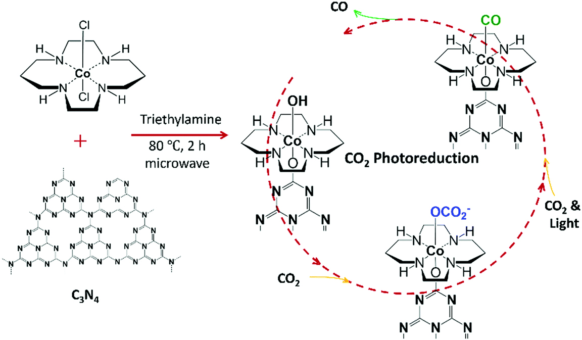 | ||
| Fig. 1 Schematic representation showing the synthesis of Co-cyclam/C3N4 and possible intermediates in photoreduction of CO2 using the prepared catalyst in the presence of a sacrificial electron donor, triethanolamine (TEOA). | ||
Although CO2 reduction on the molecular Co-cyclam catalyst has been previously studied and well understood,27–29 the working mechanism of Co-cyclam/C3N4 is still unclear, because of the lack of knowledge about the geometric details of the Co atom environment in the photocatalytic process. X-ray absorption fine structure (XAFS) is an element-specific technique for studying local structure at the atomic and molecular scales.30,31 XAFS data can provide us with detailed information, such as the inter-atomic distances, the number of nearest atoms, bond length disorder, charge states of elements.30,32 X-ray absorption near edge structure (XANES) spectra are particularly sensitive to the electronic structure of the absorber and its environment.30,31,33 However, it is difficult to extract the structure information stored in XANES data, especially when the weight loading of metals in systems such as SACs is low and when different absorbing atom environments coexist in the reaction.34,35
In SAC samples, heterogeneity of local structures is very common, and XANES spectra represent ensemble information masking the underlying heterogeneity.19,36,37 The challenge is, therefore, twofold. Firstly, there is a need to disentangle coexisting structures that contribute to the ensemble-averaged XANES spectra. Secondly, it is difficult to directly resolve the structure from the spectrum. The first challenge could be solved if spectra that correspond to unique structures could be isolated. To solve the first part, several approaches have been proposed, ranging from forward modelling38,39 to spectral deconvolution methods, such as principal component analysis (PCA),40 linear combination analysis,41 and multivariate curve resolution-alternating least square (MCR-ALS).40 The latter approaches are particularly attractive if a series of spectra are available, such as when the sample is exposed to reaction conditions, where the speciation of different structures of catalytically active metal complexes changes with the reaction. In that case, a sequence of XANES spectra collected during the reaction can be interpreted as a combination of spectra coming from unique species with unique local geometry. To solve the second problem, recently developed machine learning (ML) approaches can be utilized to determine the structure from XANES spectra. By utilizing a large amount of simulated XANES data as features, and structural descriptors such as interatomic distances, coordination numbers – as corresponding labels, ML models, such as the neural network (NN),42 can be trained to map XANES features to structural descriptors.43–46 After training the model with theoretical spectra, the NN can be used to make predictions on the experimental data to extract unknown structural descriptors.47,48 ML-assisted XANES analysis has been applied to mono- and bimetallic nanoparticles,34,43,49 size-selected clusters,50 metal clusters,40 and metal oxide clusters,51 and SACs.52 ML-based extended X-ray absorption fine structure (EXAFS) analysis of SACs was reported recently.53
In this work, we applied a ML-assisted analysis of XANES to solve the structure of the prepared Co SAC (Co-cyclam/C3N4) in photocatalytic CO2 reduction. Experimental XANES spectra collected during the reaction were first analysed to extract spectra that correspond to unique states of the SAC during the reaction. To extract the number of the species present during the entire reaction, PCA was applied on the XANES spectra. Furthermore, K-means clustering54 was applied to the PCA components to visualize the samples with similar features in one cluster. For the duration of the photocatalysis reaction, both PCA and K-means clustering of XANES spectra suggested the presence of two species. Hence, a linear combination fitting (LCF) was used to extract the mixing fraction of the two species as the function of reaction time. As an illustration of the NN-assisted XANES analysis method, we used it to identify the local structural descriptors for one of the identified species, containing a CO group attached to the Co SAC.
Experimental details
Data collection
As mentioned earlier in the text, the Co SAC was prepared by grafting Co-cyclam on C3N4 in the presence of triethylamine (Fig. 1).23 In our synthesis, triethylamine serves as a weak base to facilitate the replacement of one of the Cl ligands with an oxygen atom on C3N4, although binding through an NH group on C3N4 is also possible.In situ X-ray absorption spectra at Co K-edge were collected at the beamline 7-BM (QAS) of NSLS-II at Brookhaven National Laboratory. Si(111) double crystal was used as a monochromator. A schematic of the complete experimental setup is shown in Fig. S1 (ESI†). All the XAFS measurements were taken in fluorescence mode. Passivated implanted planar silicon (PIPS) detector was used for the detection of fluorescence from the sample. Helium gas was flown in a flight tube/path of X-ray to reduce the absorption by air. A homemade setup consisting of a reactor cell, a bubbler, and gas tubes was utilized to ensure the success of the arrival of the incident white light on the sample surface and enable gas–solid interface detection. The reactor cell, shown in Fig. S1 (ESI†), mainly consists of one polytetrafluoroethylene (PTFE) body with two windows, which can be sealed tightly by one piece of tape with one O-ring, one metal part, and two screws on each side. An appropriate volume of acetonitrile was filled in the bubbler, through which the gas entered the reactor cell. At first, a layer of Co-cyclam/C3N4 powder was spread on the tape. One drop of triethanolamine (TEOA) was dripped on the powder as electron donor. This material was taped on the PTFE body of the cell, and the cell was sealed tightly with O-rings, metal parts, and screws. The inlet and outlet gas tubes were connected to the holes on the top of the PTFE body through needles. To obtain a gas-tight system, all the connections were coated with vacuum grease. During the measurement, a customized cell with the sample was positioned at 45° with respect to the X-ray beam direction for fluorescence mode of measurement. Light generated from a halogen lamp with wavelength between 350 nm and 800 nm was introduced using an optical fiber, hitting on the sample where TEOA was introduced. During the experiment, the distance between the fiber head and the cell window was fixed at 12 cm. Before the experiment, N2 gas was used to purge the whole system for 15 minutes. CO2 gas was flown through the acetonitrile bubbler for at least 15 minutes before the light and X-rays were turned on. CO2 gas flow was continuous throughout the experiment.
All measurements were performed at room temperature. XAFS data were collected for the fresh sample, sample before the photocatalysis reaction, during the reaction for approximately 143 min, and after the reaction.
Qualitative XANES analysis
The raw XAFS spectra were analysed utilizing the Athena and Artemis interfaces of the Demeter software package.55 The normalized XANES spectra are shown in Fig. 2. The spectrum of red dots is the XANES spectrum of the fresh sample without any treatment. The black spectrum is the XANES of the sample with TEOA. The blue spectrum is the XANES of the sample with TEOA and CO2 purge. The spectra from green to yellow are the XANES spectra of eight samples with TEOA, CO2 purge, and light on from the beginning to 143 minutes and two spectra after the reaction with the light off. As the photocatalytic reaction progresses, the spectra (from dark green to yellow in Fig. 2) also change, and the peak intensities at 7724 eV keep increasing and start overlapping at 112 minutes. As shown in Fig. 2, all the spectra except for the one of the fresh sample intersect at three isosbestic points. The three isosbestic points indicate that two (and only two) constituents are being mixed in different amounts to make the series of spectra of these samples.56 The fact that the XANES of the fresh sample does not cross the isosbestic points indicates that the fresh sample has a different and unique feature in XANES from the rest of the samples.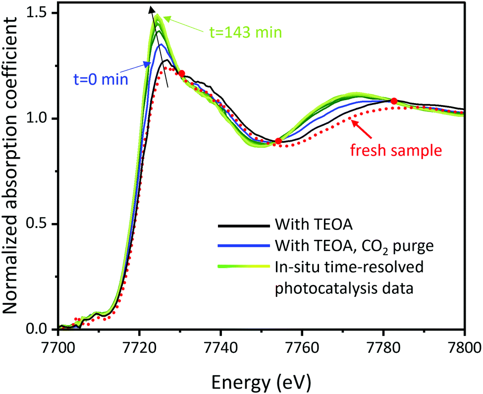 | ||
| Fig. 2 XANES spectra of the fresh sample, the sample during the photocatalysis reaction, and the ones after reaction. | ||
Additionally, two more control experiments were conducted to understand the mechanism of photocatalytic CO2 reduction using Co-cyclam/C3N4. To demonstrate the necessity of TEOA as electron donor, a control experiment without TEOA was conducted. XANES spectra obtained from this experiment are shown in Fig. S2 (ESI†). In the absence of TEOA as an electron donor, all the XANES spectra overlap with each other, indicating no structural change and no reaction. Another control experiment with N2 instead of CO2 was conducted (Fig. S3 and S4, ESI†) to show the specificity of CO2 in the reaction. As it can be seen from Fig. S3 (ESI†), changes in the spectra are much less significant under N2 than under CO2, confirming the catalyst's activity towards CO2 adsorption (and subsequent reduction).
Results and discussion
Principal component analysis (PCA) of XANES
To analyse the components involved in the collection of XANES spectra, PCA analysis was used. PCA is a technique to reduce the dimensionality of large datasets and increase interpretability while minimizing information loss, by creating new uncorrelated variables that successively maximize variance.57 When PCA is applied on XAFS analysis, the n eigenvectors necessary to reconstruct the data, the principal eigenvectors, represent the presence of n distinct species in the original spectra.58 The number of the principal components indicates the number of different species in the series.58,59PCA was applied on two sets of XANES spectra (in the energy range from 7699.9 eV to 7811.6 eV), one with all samples and one without the fresh sample. The PCA scree plot, Fig. 3, shows a comparison of eigenvalues obtained from the PCA of the two sets of data. When the spectrum of the fresh sample is included in PCA, one more component (shown by red colour in Fig. 3) is required than the ones without the fresh sample (shown by black colour in Fig. 3). Therefore, it is further confirmed that SAC molecules in the fresh sample have a unique structure as compared to the ones during photocatalysis, which is consistent with XANES spectral features. The total number of distinct species is estimated to be three, including one species of the fresh sample and two species observed in the process of reaction.
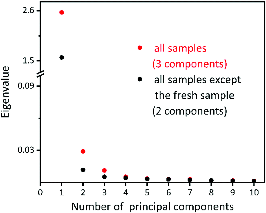 | ||
| Fig. 3 PCA scree plot showing the result from two sets of XANES spectra, one of all the samples (red) and another one of all the samples except for the fresh sample. | ||
In order to group the samples with similar features, a 2D PCA-projection was performed (Fig. 4). Principal component 1 (PC1) accounts for 97.6% of the total variation around all the spectra, and PC2 accounts for 1.11%. Therefore, using the first two principal components is sufficient to account for most of the structural information in the spectra, and the remaining components appear to be caused primarily by noise in the data. In PCA projection plots, if the data points are closer to each other, they have more similar features. PCA projection plot shows that samples with similar features cluster together. In Fig. 4, the fresh sample is away from the rest of the data points and stands out as an anomaly, which is consistent with a different molecular structure of the fresh sample.
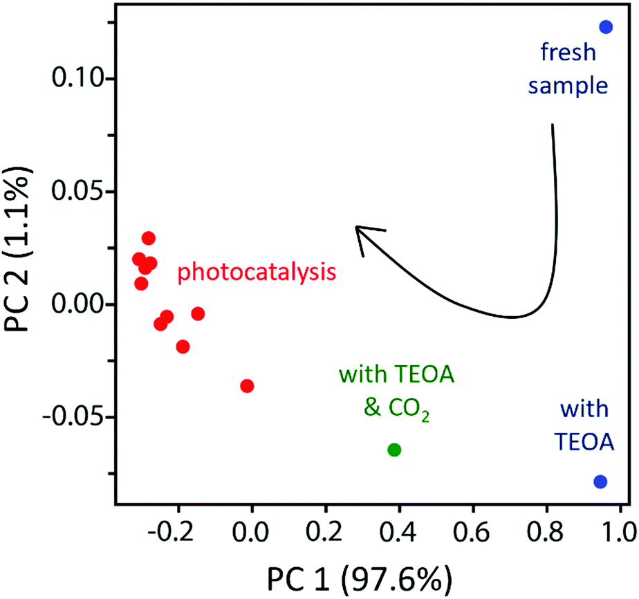 | ||
| Fig. 4 Plot of 1st and 2nd PCA components of each XANES spectra followed by a K-means clustering (different colours represent different clusters). PC 1 accounts for 97.6% of the total variation around all the spectra, and PC 2 accounts for 1.11%. | ||
To quantitively group the data points with similar features into one cluster, K-means clustering was applied on PCA-projected data to obtain more supportive evidence. The number of clusters was specified as three since there are three estimated species as shown in the PCA scree plot in Fig. 3. The result of K-mean clustering is shown in Fig. 4 with three different colours corresponding to each cluster. The fresh sample and the sample with TEOA were grouped as the first cluster shown in blue in Fig. 4; the sample with TEOA and CO2 purge before the light was singled out as the second cluster in green; and the samples during reaction with the light on and after reaction with the light off were grouped as the third cluster in red. The results of K-means clustering are consistent with the PCA results for XANES spectra.
Linear combination fitting
The PCA results demonstrate that two species were present during the light-reduced reaction. In this case of time-dependent linear transformation of structures, the mixing fraction can be obtained by applying linear combination fitting (LCF) on the XANES spectra (Fig. 5). The XANES spectrum of the sample right before the light irradation was chosen as the first standard, and the XANES spectrum of the sample at the end of the reaction (143 min) was chosen as the second standard. Based on Fig. 5, the reaction reached a steady state at approximately 112 min, indicating that the reaction sites on the SACs were saturated and fully converted to the final structure. The reaction was reproducible, as evident from the comparison of Fig. S5(a) with (b) (ESI†), and Fig. S6(a) with (b) (ESI†). The same LCF analysis was performed on results collected under N2 (Fig. S4, ESI†). A significantly smaller mixing fraction was obtained under N2, confirming the involvement of CO2 in the catalytic cycle.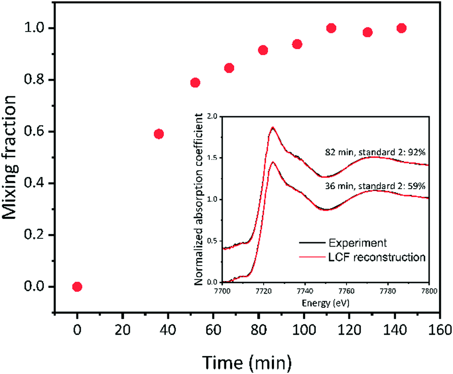 | ||
| Fig. 5 Linear combination fitting results showing the obtained mixing fraction of standard two. Standard one is the sample with TEOA and CO2 purge before light. Standard two is the sample with light on for 143 min for reaction. Inset shows a comparison between the experimental XANES spectrum and the corresponding reconstruction of XANES spectrum from LCF result at two different reaction times. | ||
Zooming in on one structural model
After the number of species and the unique spectra corresponding to such species are isolated, the challenge is to analyse the spectra in terms of the structure of each SAC species. The hypothesis of the molecular structure of each stage was elucidated and illustrated in Fig. 6 and explained in the next section.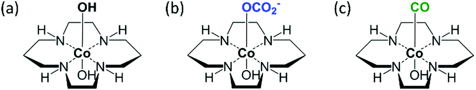 | ||
| Fig. 6 Proposed structures of Co(III) complex related to CO2 reduction on Co-cyclam/C3N4, including the fresh sample(a), the sample with TEOA and CO2 before light (b), the sample at the end of the reaction (the product structure, c). | ||
Structure hypothesis
In our study, C3N4 and Co-cyclam were prepared following our established methods.23 During the photocatalysis reaction, C3N4 absorbed light and generated the photoexcited electrons and holes.24 The electrons were transferred to the atomically dispersed cobalt atoms and sequentially reacted with CO2 while the holes were annihilated by the sacrificial electron donor, TEOA. In the following text, simplified structures were used to represent the complex for the purpose of simplicity. During the catalyst synthesis, the Cl ligands of Co-cyclam were substituted by hydroxyl groups in the presence of triethylamine (denoted as “Co-cyclam–OH”, shown in Fig. 6(a)). Under purging CO2 without light, CO2 adsorption happened on the hydroxyl groups exposed on the catalyst surface.60,61 The hypothesized structure is shown in Fig. 6(b), denoted as “Co-cyclam–OCO2”, ready for the following reaction step once the light was on. After a series of transformations with CO2 and light, the product CO formed on the catalytic cobalt sites. The hypothesized structure is shown in Fig. 6(c), denoted as “Co-cyclam–CO”. As CO desorbs and the cobalt site returns to its original state, the active catalytic sites readily enter the next catalytic round.EXAFS analysis and fitting
Examination of the raw EXAFS spectra and their quantitative analysis by fitting were used to propose the model of the local environment of Co-cyclam–CO. The Fourier transformed EXAFS (FT-EXAFS) of the fresh sample and the product sample (Fig. S7, ESI†, structures shown in Fig. 6(a) and (c), respectively) show qualitative evidence of local structural changes due to the reaction. In R-space spectra shown in Fig. S7 (ESI†), after 143 min of reaction with CO2 and light, the presence of the second peak at 2.4 Å, which is absent in the fresh sample, indicates the Co–CO contribution as the proposed structure shown in Fig. 6(c). Indeed, the Co–C–O linkage is quasi-collinear, thus contributing a strong signal to the distance range corresponding to the second distance, due to the forward multiple scattering paths.62,63EXAFS fitting was used to further zoom in on the approximate model for the local environment of Co-cyclam–CO, the final reaction product, shown in Fig. 6(c). In R-space spectra in Fig. S7 (ESI†), the presence of a peak at 1.4 Å corresponds to Co–O (dO) and Co–N (dN) contributions (uncorrected for the photoelectron phase shift) from the first shell. The contribution of Co–O and Co–N is difficult to distinguish by EXAFS analysis because the bond lengths of Co–O (∼1.92 Å),64 Co–N (∼1.98 Å)64 are close. Thus, the Co–O scattering path was chosen to fit the first peak.
For the second shell, we expect the origin of the peak at 2.4 Å to be due to the Co–C–O linkage that may form after reaction as shown in the proposed structure (Fig. 6(c)).60,61 The best fitting result was obtained by including the forward double scattering Co–C–O path to fit the second peak. The fitting result is shown in Table S2 and Fig. S8 (ESI†). It is important to note that EXAFS data quality is limited, and only one important multiple-scattering path was chosen for the second peak analysis, hence the fitting results have high uncertainties. Despite that, the raw EXAFS and their fitting analysis result can be used to qualitatively validate the model for XANES-NN analysis using the molecular structure shown in Fig. 6(c).
Artificial neural network for XANES analysis
Artificial NN was constructed to refine the local geometry of Co-cyclam–CO, as shown schematically in Fig. 7. To validate the NN-XANES approach, we performed sensitivity analysis first.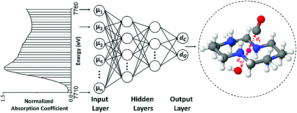 | ||
| Fig. 7 A schematic that represents the application of NN-XANES to SACs system of Co-cyclam–CO. | ||
Sensitivity analysis
The key assumption behind utilizing ML methods for structural refinement using spectra is that a correlation exists between the structural descriptors (output) and the corresponding XANES spectrum (input). A sensitivity study was conducted to check if Co SAC XANES spectra are sensitive to a set of descriptors chosen for characterizing the local geometry of SAC in this work. One such descriptor is dC, the bond length between Co and C of the carbonyl. Before generating theoretical XANES spectra for the unknown structure with FEFF calculation, experimental XANES of a reference compound, CoO, was chosen as a standard to optimize the FEFF parameters. Based on the optimized FEFF parameters, theoretical XANES spectra of Co-cyclam–CO with different bond lengths of Co–C were generated by FEFF calculation. The result of this sensitivity analysis of dC is shown in Fig. S9 (ESI†). The first two peak features in the range from 7724 eV to 7737 eV are clearly affected by the change of dC.Method description
Artificial NN was utilized to quantify the local structure details of Co-cyclam–CO. For the training, validation, and testing, a data set of theoretical XANES spectra was created using FEFF code with optimized parameters as explained above. At first, eight descriptors, including six bond lengths and two bond angles shown in Fig. S12 (ESI†), were varied at the same time to generate around 28![[thin space (1/6-em)]](https://www.rsc.org/images/entities/char_2009.gif) 000 different theoretical molecular structures for XANES calculation. However, even with 28000 theoretical XANES spectra of eight descriptors changing, the error from the NN prediction was too high to refine the structure from XANES. Therefore, a few additional assumptions were introduced to the theoretical structure to reduce the number of descriptors. First, the bond lengths of Co and the four N atoms from the cyclam were fixed to the values obtained from DFT simulation. The values for the DFT calculation results are shown in Fig. S10 of ESI.† Second, the functional group was assumed to be perpendicular to the plane of the four N atoms in the cyclam. Third, Co, C, and O in the carbonyl are in the same line. Forth, the OH group is assumed to be at the bottom of Co-cyclam. As a result, only two target descriptors were extracted from NN: the distance between Co and C from the carbonyl, dC, and the distance between Co and bottom O, dO, as shown in Fig. 7. During the simulation of theoretical XANES, the dC and dO values were varied in the range of [1.90, 2.35] Å, and [1.70, 2.20] Å respectively (Fig. 8). 5000 values were selected from a uniform distribution in the range for each descriptor. Hence, 5000 different molecular structures with specific descriptors were generated. XANES spectra of these 5000 molecules were calculated using FEFF code. The calculated theoretical XANES spectra are shown in Fig. 8 from yellow to green, compared with the experimental XANES spectrum shown in black. Based on Fig. 8, the experiment XANES spectrum is within the range of the theoretical XANES spectra, indicating these theoretical spectra should include the features from the experimental one.
000 different theoretical molecular structures for XANES calculation. However, even with 28000 theoretical XANES spectra of eight descriptors changing, the error from the NN prediction was too high to refine the structure from XANES. Therefore, a few additional assumptions were introduced to the theoretical structure to reduce the number of descriptors. First, the bond lengths of Co and the four N atoms from the cyclam were fixed to the values obtained from DFT simulation. The values for the DFT calculation results are shown in Fig. S10 of ESI.† Second, the functional group was assumed to be perpendicular to the plane of the four N atoms in the cyclam. Third, Co, C, and O in the carbonyl are in the same line. Forth, the OH group is assumed to be at the bottom of Co-cyclam. As a result, only two target descriptors were extracted from NN: the distance between Co and C from the carbonyl, dC, and the distance between Co and bottom O, dO, as shown in Fig. 7. During the simulation of theoretical XANES, the dC and dO values were varied in the range of [1.90, 2.35] Å, and [1.70, 2.20] Å respectively (Fig. 8). 5000 values were selected from a uniform distribution in the range for each descriptor. Hence, 5000 different molecular structures with specific descriptors were generated. XANES spectra of these 5000 molecules were calculated using FEFF code. The calculated theoretical XANES spectra are shown in Fig. 8 from yellow to green, compared with the experimental XANES spectrum shown in black. Based on Fig. 8, the experiment XANES spectrum is within the range of the theoretical XANES spectra, indicating these theoretical spectra should include the features from the experimental one.
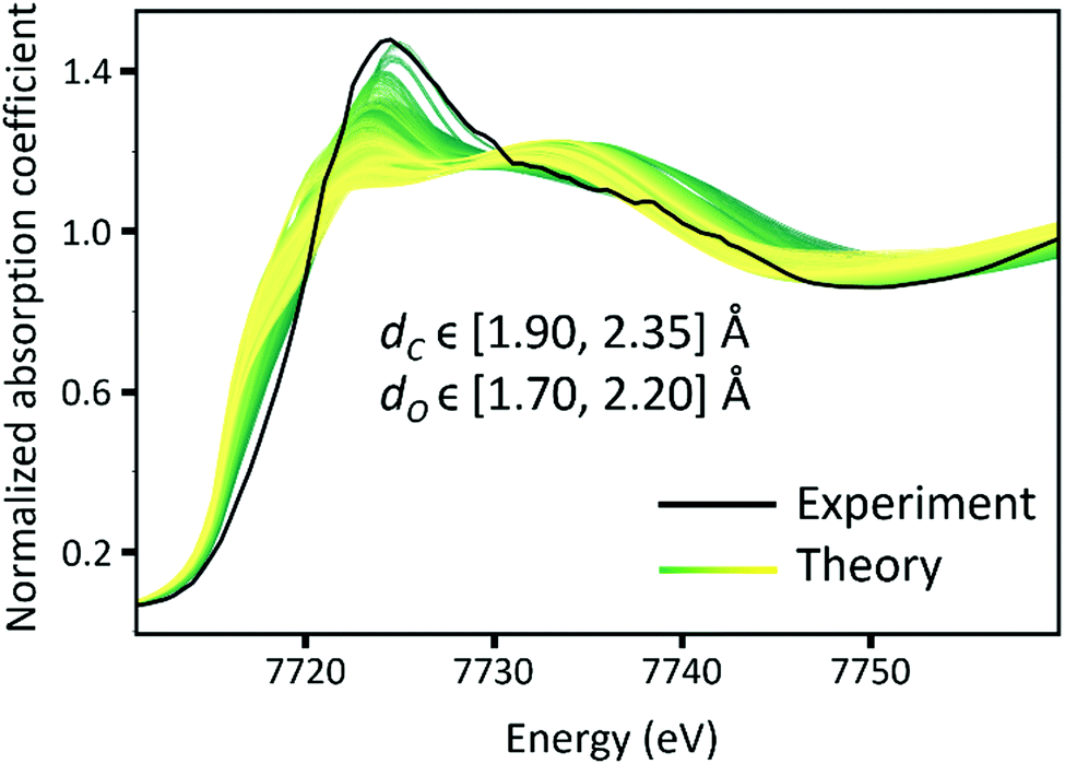 | ||
| Fig. 8 Comparison between the experimental XANES spectrum of Co-cyclam–CO (black) and all the theoretical XANES spectra. The spectra with the colour from green to yellow are simulated XANES with two descriptors changing (dC and dO). | ||
72% of the theoretical data were used for the model training, 8% for model selection, and 20% for testing. The test results are shown in Fig. 9 with a root-mean-squared error of 0.017 Å. Further calculations of error estimates from the test error distributions are also shown in Fig. S13 and S14 (ESI†) for dC and dO respectively. As Fig. 9 suggests, NN shows good prediction power over the test dataset. Hence this trained model can be used on the experimental XANES spectra.
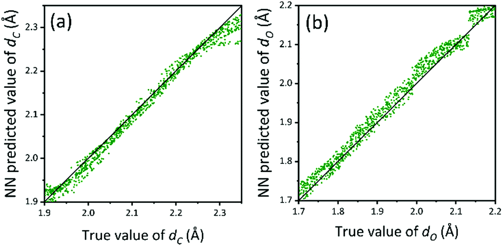 | ||
| Fig. 9 Prediction accuracy of the NN models on the test dataset. (a) dCversus predicted dC (Å), (b) dOversus predicted dO (Å). | ||
NN prediction
The trained NN described above was used to predict the dC and dO values from the experimental XANES spectrum of the reaction end-product. A schematic of NN-assisted XANES is also shown in Fig. 7. The predicted values are shown in Table 1 along with EXAFS fitting results that are given for comparison. For the first shell, the NN predicted results are consistent with EXAFS results and provide more details than the approximate EXAFS model that assumes that all atoms in the first shell of Co are at the same distance. For the second shell, the result based on the XANES deviates from the EXAFS fitting result, which we attribute to the approximations used in EXAFS model (vide supra). Fig. 10 shows the agreement between the XANES spectrum of the molecule reconstructed from the NN predictions (shown in red) and the experimental spectrum (shown in black).| First Shell | Second Shell | |||
|---|---|---|---|---|
| d N (Å) | d C (Å) | d O (Å) | d Co–CO (Å) | |
| a These values were fixed to be equal to dN in EXAFS fitting model. b This value was fixed to the values obtained from DFT calculations. c The Co–C–O distance (dCo–CO) was obtained as the sum of 1.965 Å (Co–C) and 1.1 Å (C–O)65 distances. | ||||
| EXAFS | 1.95(6) | 1.95(6)a | 1.95(6)a | 3.31(7) |
| NN prediction | 1.990b | 1.965(10) | 2.135(20) | 3.065(10)c |
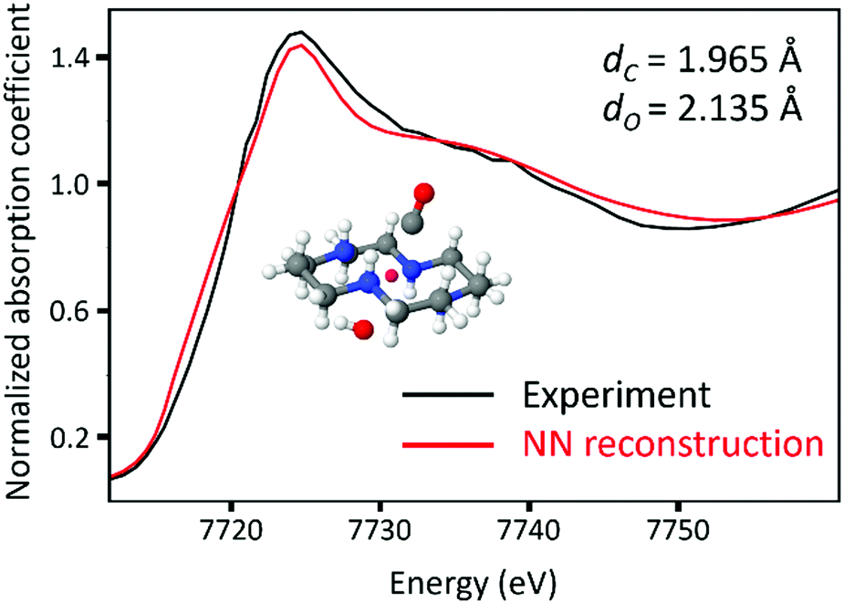 | ||
| Fig. 10 The comparison of the experimental XANES spectra (black) and the theoretical XANES spectra reconstructed from the descriptor values predicted from NN. | ||
Conclusions
In situ XAFS is a powerful technique to investigate the local structures of catalytic sites and their evolution in a variety of applications.66,67 When transition metal-based molecular catalysts in general and “single-atom” catalysts in particular are grafted onto heterogeneous surfaces, their structures and properties might be significantly changed, and additional transformations occur during catalytic reactions. In addition, it remains unclear how catalysis on surfaces differs from that in the homogeneous system using their molecular counterpart. In situ XAFS characterization and subsequent data analysis could render key insights into these unknown questions that are difficult to answer using other techniques. Conventional analysis by EXAFS data fitting and qualitative XANES modelling using theoretical spectroscopy methods have been limited in the case of SACs which typically have low weight loadings and complex nearest neighbour environments.In this study, in situ XAFS spectra of Co-cyclam grafted on C3N4 were collected during photocatalysis. Using complementary machine learning methods, key intermediates on this surface catalyst, similar to those produced using the homogeneous Co-cyclam, were clearly confirmed. In addition, predictions based on neural network-assisted XANES method provide new results on the local structure of Co SACs at the end stage of the reaction. Our work opens up the opportunity for similar investigations of the local structural information at each reaction stage by this ML-assisted XANES analysis and, as a result, for understanding the electron transfer process of CO2 reduction on Co-cyclam/C3N4. This approach can be further extended to deciphering the structures and reaction mechanisms of other heterogenized molecular catalysts.
Conflicts of interest
There are no conflicts to declare.Acknowledgements
AIF and GL acknowledge support by the National Science Foundation Grant CHE 2102299 (to AIF) and CHE-2102655 (to GL). This research used beamline 7-BM (Quick X-ray Absorption and Scattering, QAS) of the National Synchrotron Light Source II, a Department of Energy (DOE) Office of Science User Facility operated by Brookhaven National Laboratory under Contract DE-SC0012704. Beamline operations were supported in part by the Synchrotron Catalysis Consortium (DOE Office of Basic Energy Sciences Grant DE-SC0012335). This research used resources of the Center for Functional Nanomaterials, which is a U.S. DOE Office of Science Facility, and the Scientific Data and Computing Center, a component of the Computational Science Initiative, at Brookhaven National Laboratory under Contract No. DE-SC0012704. S. X. would like to thank S. Khan for his help with coding. We would like to thank S. Ehrlich, L. Ma, and N. Marinkovic for help with XAFS data collection.Notes and references
- A. M. Appel, J. E. Bercaw, A. B. Bocarsly, H. Dobbek, D. L. DuBois, M. Dupuis, J. G. Ferry, E. Fujita, R. Hille, P. J. A. Kenis, C. A. Kerfeld, R. H. Morris, C. H. F. Peden, A. R. Portis, S. W. Ragsdale, T. B. Rauchfuss, J. N. H. Reek, L. C. Seefeldt, R. K. Thauer and G. L. Waldrop, Chem. Rev., 2013, 113, 6621–6658 CrossRef CAS PubMed.
- D. Gilfillan and G. Marland, Earth Syst. Sci. Data, 2021, 13, 1667–1680 CrossRef.
- S. C. Doney, V. J. Fabry, R. A. Feely and J. A. Kleypas, Annu. Rev. Mar. Sci., 2009, 1, 169–192 CrossRef PubMed.
- N. Teixido, M. C. Gambi, V. Parravacini, K. Kroeker, F. Micheli, S. Villeger and E. Ballesteros, Nat. Commun., 2018, 9, 5149 CrossRef CAS PubMed.
- J. P. Pradier and C.-M. Pradier, Carbon dioxide chemistry: environmental issues, Elsevier, 2014 Search PubMed.
- Z. H. Lee, S. Sethupathi, K. T. Lee, S. Bhatia and A. R. Mohamed, Renewable Sustainable Energy Rev., 2013, 28, 71–81 CrossRef.
- C. Song, ACS Symp. Ser., 2002, 1–30 CAS.
- J. Ma, N. N. Sun, X. L. Zhang, N. Zhao, F. K. Mao, W. Wei and Y. H. Sun, Catal. Today, 2009, 148, 221–231 CrossRef CAS.
- K. Li, B. S. Peng and T. Y. Peng, ACS Catal., 2016, 6, 7485–7527 CrossRef CAS.
- Q. S. Wang, D. F. Zhang, Y. Chen, W. F. Fu and X. J. Lv, ACS Sustainable Chem. Eng., 2019, 7, 6430–6443 CrossRef CAS.
- B. Q. Xia, Y. Z. Zhang, J. R. Ran, M. Jaroniec and S. Z. Qiao, ACS Cent. Sci., 2021, 7, 39–54 CrossRef CAS PubMed.
- S. Mitchell, J. M. Thomas and J. Perez-Ramirez, Catal. Sci. Technol., 2017, 7, 4248–4249 RSC.
- J. Y. Liu, ACS Catal., 2017, 7, 34–59 CrossRef CAS.
- X. H. Jiang, L. S. Zhang, H. Y. Liu, D. S. Wu, F. Y. Wu, L. Tian, L. L. Liu, J. P. Zou, S. L. Luo and B. B. Chen, Angew. Chem., Int. Ed., 2020, 59, 23112–23116 CrossRef CAS PubMed.
- P. Zhou, H. Chen, Y. G. Chao, Q. H. Zhang, W. Y. Zhang, F. Lv, L. Gu, Q. Zhao, N. Wang, J. S. Wang and S. J. Guo, Nat. Commun., 2021, 12, 4412 CrossRef CAS PubMed.
- H. B. Zhang, G. G. Liu, L. Shi and J. H. Ye, Adv. Energy Mater., 2018, 8, 1701343 CrossRef.
- J. J. Yang, Z. Z. Sun, K. L. Yan, H. Z. Dong, H. Y. Dong, J. K. Cui, X. T. Gong, S. L. Han, L. M. Huang and J. W. Wen, Green Chem., 2021, 23, 2756–2762 RSC.
- J. Di, C. Chen, S. Z. Yang, S. M. Chen, M. L. Duan, J. Xiong, C. Zhu, R. Long, W. Hao, Z. Chi, H. L. Chen, Y. X. Weng, J. X. Xia, L. Song, S. Z. Li, H. M. Li and Z. Liu, Nat. Commun., 2019, 10, 2840 CrossRef PubMed.
- C. Gao, S. M. Chen, Y. Wang, J. W. Wang, X. S. Zheng, J. F. Zhu, L. Song, W. K. Zhang and Y. J. Xiong, Adv. Mater., 2018, 30, 1704624 CrossRef PubMed.
- R. X. Qin, P. X. Liu, G. Fu and N. F. Zheng, Small Methods, 2018, 2, 1700286 CrossRef.
- L. Jiao and H. L. Jiang, Chem, 2019, 5, 786–804 CAS.
- J. H. Zhang, W. Yang, M. Zhang, H. J. Wang, R. Si, D. C. Zhong and T. B. Lu, Nano Energy, 2021, 80, 105542 CrossRef CAS.
- P. P. Huang, S. A. Pantovich, N. O. Okolie, N. A. Deskins and G. H. Li, ChemPhotoChem, 2020, 4, 420–426 CrossRef CAS.
- J. Fu, S. Wang, Z. Wang, K. Liu, H. Li, H. Liu, J. Hu, X. Xu, H. Li and M. Liu, Front. Phys., 2020, 15, 33201 CrossRef.
- P. P. Huang, J. H. Huang, S. A. Pantovich, A. D. Carl, T. G. Fenton, C. A. Caputo, R. L. Grimm, A. I. Frenkel and G. H. Li, J. Am. Chem. Soc., 2018, 140, 16042–16047 CrossRef CAS PubMed.
- P. P. Huang, J. H. Huang, J. Y. Li, L. Zhang, J. He, C. A. Caputo, A. I. Frenkel and G. H. Li, ChemNanoMat, 2021, 7, 1051–1056 CrossRef CAS.
- S. Matsuoka, K. Yamamoto, T. Ogata, M. Kusaba, N. Nakashima, E. Fujita and S. Yanagida, J. Am. Chem. Soc., 1993, 115, 601–609 CrossRef CAS.
- T. Ogata, S. Yanagida, B. S. Brunschwig and E. Fujita, J. Am. Chem. Soc., 1995, 117, 6708–6716 CrossRef CAS.
- J. Schneider, H. Jia, J. T. Muckerman and E. Fujita, Chem. Soc. Rev., 2012, 41, 2036–2051 RSC.
- G. Bunker, Introduction to XAFS: a practical guide to X-ray absorption fine structure spectroscopy, Cambridge University Press, 2010 Search PubMed.
- A. Gaur, B. D. Shrivastava and H. Nigam, Proc. Indian Natl. Sci. Acad., 2013, 79, 921–966 Search PubMed.
- D. C. Koningsberger and R. Prins, X-ray absorption: principles, applications, techniques of EXAFS, SEXAFS and XANES, 1987 Search PubMed.
- J. J. Rehr and A. L. Ankudinov, Coord. Chem. Rev., 2005, 249, 131–140 CrossRef CAS.
- J. Timoshenko and A. I. Frenkel, ACS Catal., 2019, 9, 10192–10211 CrossRef CAS.
- A. Piovano, G. Agostini, A. I. Frenkel, T. Bertier, C. Prestipino, M. Ceretti, W. Paulus and C. Lamberti, J. Phys. Chem. C, 2011, 115, 1311–1322 CrossRef CAS.
- J. A. Rodríguez, J. C. Hanson and P. J. Chupas, In-situ characterization of heterogeneous catalysts, John Wiley & Sons, 2013 Search PubMed.
- M. Kottwitz, Y. Li, H. Wang, A. I. Frenkel and R. G. Nuzzo, Chemistry-Methods, 2021, 1, 278–294 CrossRef.
- S. Roy, Y. Liu, M. Topsakal, E. Dias, R. Gakhar, W. C. Phillips, J. F. Wishart, D. Leshchev, P. Halstenberg, S. Dai, S. K. Gill, A. I. Frenkel and V. S. Bryantsev, J. Am. Chem. Soc., 2021, 143, 15298–15308 CrossRef CAS PubMed.
- S. K. Gill, J. H. Huang, J. Mausz, R. Gakhar, S. Roy, F. Vila, M. Topsakal, W. C. Phillips, B. Layne, S. Mahurin, P. Halstenberg, S. Dai, J. F. Wishart, V. S. Bryantsev and A. I. Frenkel, J. Phys. Chem. B, 2020, 124, 1253–1258 CrossRef CAS PubMed.
- Y. Liu, A. Halder, S. Seifert, N. Marcella, S. Vajda and A. I. Frenkel, ACS Appl. Mater. Interfaces, 2021, 13, 53363–53374 CrossRef CAS PubMed.
- A. Halder, C. Lenardi, J. Timoshenko, A. Mravak, B. Yang, L. K. Kolipaka, C. Piazzoni, S. Seifert, V. Bonacic-Koutecky, A. I. Frenkel, P. Milani and S. Vajda, ACS Catal., 2021, 11, 6210–6224 CrossRef CAS.
- N. Marcella, Y. Liu, J. Timoshenko, E. J. Guan, M. Luneau, T. Shirman, A. M. Plonka, J. E. S. van der Hoeven, J. Aizenberg, C. M. Friend and A. I. Frenkel, Phys. Chem. Chem. Phys., 2020, 22, 18902–18910 RSC.
- J. Timoshenko, D. Y. Lu, Y. W. Lin and A. I. Frenkel, J. Phys. Chem. Lett., 2017, 8, 5091–5098 CrossRef PubMed.
- T. Mizoguchi and S. Kiyohara, Microscopy, 2020, 69, 92–109 CrossRef CAS PubMed.
- A. A. Guda, S. A. Guda, A. Martini, A. L. Bugaev, M. A. Soldatov, A. V. Soldatov and C. Lamberti, Radiat. Phys. Chem., 2020, 175, 108430 CrossRef CAS.
- M. R. Carbone, S. Yoo, M. Topsakal and D. Y. Lu, Phys. Rev. Mater., 2019, 3, 033604 CrossRef CAS.
- M. R. Carbone, M. Topsakal, D. Y. Lu and S. Yoo, Phys. Rev. Lett., 2020, 124, 156401 CrossRef CAS PubMed.
- P. K. Routh, Y. Liu, N. Marcella, B. Kozinsky and A. I. Frenkel, J. Phys. Chem. Lett., 2021, 12, 2086–2094 CrossRef CAS PubMed.
- J. Timoshenko, C. J. Wrasman, M. Luneau, T. Shirman, M. Cargnello, S. R. Bare, J. Aizenberg, C. M. Friend and A. I. Frenkel, Nano Lett., 2019, 19, 520–529 CrossRef CAS PubMed.
- J. Timoshenko, A. Halder, B. Yang, S. Seifert, M. J. Pellin, S. Vajda and A. I. Frenkel, J. Phys. Chem. C, 2018, 122, 21686–21693 CrossRef CAS.
- Y. Liu, N. Marcella, J. Timoshenko, A. Halder, B. Yang, L. Kolipaka, M. J. Pellin, S. Seifert, S. Vajda, P. Liu and A. I. Frenkel, J. Chem. Phys., 2019, 151, 164201 CrossRef PubMed.
- A. A. Guda, S. A. Guda, K. A. Lomachenko, M. A. Soldatov, I. A. Pankin, A. V. Soldatov, L. Braglia, A. L. Bugaev, A. Martini, M. Signorile, E. Groppo, A. Piovano, E. Borfecchia and C. Lamberti, Catal. Today, 2019, 336, 3–21 CrossRef CAS.
- X. Liu, L. Zheng, C. Han, H. Zong, G. Yang, S. Lin, A. Kumar, A. R. Jadhav, N. Q. Tran and Y. Hwang, Adv. Funct. Mater., 2021, 31, 2100547 CrossRef CAS.
- F. Meirer, Y. J. Liu, E. Pouyet, B. Fayard, M. Cotte, C. Sanchez, J. C. Andrews, A. Mehta and P. Sciau, J. Anal. At. Spectrom., 2013, 28, 1870–1883 RSC.
- B. Ravel and M. Newville, J. Synchrotron Radiat., 2005, 12, 537–541 CrossRef CAS PubMed.
- S. Calvin, XAFS for Everyone, CRC press, 2013 Search PubMed.
- I. T. Jolliffe and J. Cadima, Philos. Trans. R. Soc., A, 2016, 374, 20150202 CrossRef PubMed.
- S. R. Wasserman, J. Phys. IV, 1997, 7, 203–205 CAS.
- S. R. Wasserman, P. G. Allen, D. K. Shuh, J. J. Bucher and N. M. Edelstein, J. Synchrotron Radiat., 1999, 6, 284–286 CrossRef CAS PubMed.
- A. J. Morris, G. J. Meyer and E. Fujita, Acc. Chem. Res., 2009, 42, 1983–1994 CrossRef CAS PubMed.
- Z. Sun, T. Ma, H. Tao, Q. Fan and B. Han, Chem, 2017, 3, 560–587 CAS.
- A. Frenkel, E. A. Stern, A. Voronel, M. Qian and M. Newville, Phys. Rev. B: Condens. Matter Mater. Phys., 1994, 49, 11662–11674 CrossRef CAS PubMed.
- A. Frenkel, E. A. Stern, A. Voronel, M. Qian and M. Newville, Phys. Rev. Lett., 1993, 71, 3485–3488 CrossRef CAS PubMed.
- A. M. Funston, W. D. McFadyen and P. A. Tregloan, Aust. J. Chem., 2002, 55, 535–538 CrossRef CAS.
- A. Chapovetsky, M. Welborn, J. M. Luna, R. Haiges, T. F. Miller and S. C. Marinescu, ACS Cent. Sci., 2018, 4, 397–404 CrossRef CAS PubMed.
- J. Timoshenko and B. R. Cuenya, Chem. Rev., 2021, 121, 882–961 CrossRef CAS PubMed.
- C. J. Chang, Y. Zhu, J. Wang, H. C. Chen, C. W. Tung, Y. C. Chu and H. M. Chen, J. Mater. Chem. A, 2020, 8, 19079–19112 RSC.
Footnote |
| † Electronic supplementary information (ESI) available: Sample details, XANES and EXAFS spectra, details of the EXAFS data fitting and machine learning – assisted XANES data analysis. See DOI: 10.1039/d1cp05513e |
| This journal is © the Owner Societies 2022 |