
Recent progress on organic exciplex materials with different donor–acceptor contacting modes for luminescent applications†
Junfeng
Guo
ab,
Yonggang
Zhen
 *c,
Huanli
Dong
*ab and
Wenping
Hu
*d
*c,
Huanli
Dong
*ab and
Wenping
Hu
*d
aBeijing National Laboratory for Molecular Science, Key Laboratory of Organic Solids, Institute of Chemistry, Chinese Academy of Sciences, Beijing 100190, China. E-mail: dhl522@iccas.ac.cn
bSchool of Chemical Sciences, University of Chinese Academy of Sciences, Beijing 100049, China
cBeijing Advanced Innovation Center for Soft Matter Science and Engineering, State Key Laboratory of Organic–Inorganic Composites, Beijing University of Chemical Technology, Beijing 100029, China. E-mail: zhenyg@buct.edu.cn
dTianjin Key Laboratory of Molecular Optoelectronic Sciences, Department of Chemistry, School of Science, Tianjin University and Collaborative Innovation Center of Chemical Science and Engineering, Tianjin 300072, China. E-mail: huwp@tju.edu.cn
First published on 1st November 2021
Abstract
Recently organic exciplex materials have captured considerable attention due to their promising luminescent applications in organic optical waveguides, lasers, nonlinear optics, light-emitting diodes and even light-emitting transistors. The emission features together with other optoelectronic properties can be tailored via intermolecular charge-transfer interactions by the judicious selection of various component materials. In this review, first we will discuss the formation mechanism and emission process of exciplexes by photoexcitation or electrical excitation, which will shed light on realizing high-efficiency luminescence and generating new optical functions. Next, we will mainly introduce the various organic exciplex materials in terms of donor–acceptor contacting modes (cocrystals, interface, blend, porous coordination, and space-limitation) and their potential applications in optoelectronic devices. Finally, we will present the current obstacles and limitations of organic exciplex materials as well as their prospects for future research.
 Junfeng Guo | Junfeng Guo grew up in AnHui Province, China. He received his bachelor's degree in applied chemistry from China university of petroleum in 2019. Since 2019, he has been a master's student under the supervision of Prof. Yonggang Zhen and Prof. Huanli Dong at the Institute of Chemistry, Chinese Academy of Sciences. His research work focuses on crystal engineering of organic photoelectric functional materials. |
 Yonggang Zhen | Dr Yonggang Zhen is a professor at Beijing University of Chemical Technology (BUCT). He received his PhD from the Institute of Chemistry, CAS (ICCAS) in 2010. From 2010 to 2013, he worked as a postdoc researcher in Prof. Eiichi Nakamura's group, at the University of Tokyo. After that, he returned to ICCAS where he was promoted to Professor in 2018. He moved to BUCT in 2021. His research focuses on design and synthesis, self-assembly and crystal engineering of organic optoelectronic materials. |
 Huanli Dong | Huanli Dong is a Professor at the Institute of Chemistry, CAS. She received her MS degree (2006) from Fujian Institute of Material Structure, CAS, and her PhD (2009) from the Institute of Chemistry, CAS. Her current research focuses on organic optoelectronic materials and devices with special attention on high mobility organic semiconductors, high mobility emissive organic semiconductors and their applications in organic field effect transistors, organic light-emitting transistors and other related integrated optoelectronic devices, and circuits. Currently, she has more than 200 refereed publications with over 13 |
 Wenping Hu | Wenping Hu is a Professor at Tianjin University. He received his PhD from the Institute of Chemistry, Chinese Academy of Sciences in 1999. Then he joined Osaka University and Stuttgart University as a research fellow of Japan Society for the Promotion of Sciences and Alexander von Humboldt, respectively. In 2003 he returned to the Institute of Chemistry from Nippon Telephone and Telegraph (Japan), and was then promoted to full professor in the institute. He was awarded the National Science Fund for Distinguished Young Scholars in 2007 and was appointed as Cheung Kong Professor of Ministry of Education of China in 2014. He was elected as an assistant president of Tianjin University in 2013 and vice president of the university in 2016. His research interests include organic semiconducting materials, single crystals and devices. He has published more than 470 refereed publications with over 15 |
1. Introduction
There is a controversial debate on the definition of an exciplex. Upon direct or local-band excitation of one component of a donor (D)–acceptor (A) pair at its local band, the excited D or A diffuses to encounter with the ground-state counterpart (A or D), affording a conventional exciplex that is stable only in the excited state.1,2 On the other hand, photoirradiation of a charge transfer (CT) complex at its CT band leads to the formation of an excited CT complex, which can be categorized as an exciplex in a broader sense, as it is undoubtedly an excited-state complex.1 An exciplex can generally be regarded as a hybrid state with a partly CT character and a certain fraction of a local excitation on one (or both) molecule(s) of the donor–acceptor system,3 which is the product of an incomplete charge separation process.4 An exciplex can be formed at D/A interfaces from the dissociation of a photoexcited Frenkel exciton in the donor or acceptor, from an electron and a hole injected electrically in a diode geometry, or from direct below-gap optical excitation in a D/A blend.5Exciplexes constitute important intermediates in many photochemical reactions in chemical or biological systems.6 As for the application in organic optoelectronics, the exciplex energy is strongly dependent on the wave-function overlap of the electron and hole on the A and D that form the CT state. While organic light emitting diodes (OLEDs) require stabilized, strong electron–hole wave-function overlap in the exciplex to achieve efficient radiative recombination, organic photovoltaics require weakly bound electron–hole pairs with poor wave-function overlap, i.e., as in a hot CT state, in order to undergo full charge separation to form free charge carriers.7 In early studies for luminescent applications, exciplex emission is of low efficiency and considered undesirable.8,9 Until recently, OLEDs with high efficiency exciplex emission have been reported10–14 and their tuneable and broad emission spectra have been exploited for white-light emission.11 Another recent breakthrough is the utilization of an exciplex-forming co-host for thermally activated delayed fluorescent (TADF) OLEDs with high efficiency.15,16
In view of the rapid development of luminescent exciplex materials, it is necessary to systematically summarize the research status of these materials and point out the development direction of luminescent exciplex materials. In this review, we focus on the donor–acceptor contacting modes, the luminescence properties of exciplex materials, and their latest luminescent applications. First, we will discuss the formation mechanism and emission process of an exciplex by photoexcitation or electrical excitation, which will shed light on realizing high-efficiency luminescence and generating new optical functions. Subsequently, we will mainly introduce the various organic exciplex materials in terms of donor–acceptor contacting modes (cocrystals, interface, blend, porous coordination, and space-limitation) and their potential application in optoelectronic devices. Finally, we will present the current obstacles and limitations of organic exciplex materials as well as their prospects for future research studies.
2. Formation and emission of an exciplex
An exciplex can be formed at D/A interfaces by local or CT photoexcitation of a D/A complex, or electrical excitation of the donor or acceptor in a diode geometry. We discuss the formation mechanism and emission process of an exciplex by photoexcitation or electrical excitation as follows.2.1 Photoexcitation generated exciplex
An exciplex generated by photoexcitation can result from local excitation of the donor or the acceptor, or CT excitation of a CT complex. Generally, CT complexes can be divided into two categories: ionic ground state CT complexes, in which the ground state involves electrons that have been transferred and nonionic ground state CT complexes, where an electron transfer occurs only after absorbing photons with sufficient energy.17,18The formation process of the ionic ground state CT complex can be explained by Mulliken's valence bond theory.19,20 The CT complex can be regarded as a resonance mixture of two different structures. The model can be described as
D + A → (D, A) ![[left over right harpoons]](https://www.rsc.org/images/entities/char_21cb.gif) (Aδ−–Dδ+)CT (Aδ−–Dδ+)CT |
| ψg ≈ aψ0(A, D) + bψ1(A−D+) |
| ψe ≈ a′ψ0(A, D) + b′ψ1(A−D+) |
The energies of the frontier molecular orbitals for an ionic ground state CT complex formed from those of the donor and acceptor in a one-electron approximation.24 Because intermixing of the ψ0 (A, D) and ψ1(A−D+) states leads to new energy levels, a new absorption CT band should appear in the optical bandgap of the donor and acceptor. The highest occupied molecular orbital (HOMO) of the complex is close to that of the donor, and its lowest unoccupied molecular orbital (LUMO) is close to that of the acceptor. Therefore, the LUMO–HOMO energy gap for an ionic ground state CT complex corresponds to the difference between the donor HOMO and acceptor LUMO energies, which is usually significantly less than the LUMO–HOMO energy gap of both the donor and acceptor. The formation of an ionic ground state CT complex is illustrated in Fig. 1a, the electrons in the HOMO will be excited into the LUMO upon CT photoexcitation, forming a CT exciton, namely an exciplex in a broad sense.
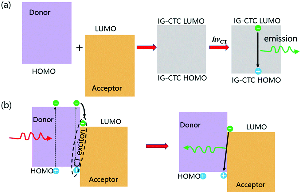 | ||
| Fig. 1 Formation of a CT exciton by photoexcitation. IG-CTC: ionic ground state CT complexes. (a) Ionic ground state CT complexes are excited and their emissions are shown. (b) Nonionic ground state CT complexes are excited and their emissions are shown. Reprinted with permission from ref. 34. Copyright © 2017, Science China Press and Springer-Verlag GmbH Germany, part of Springer Nature. | ||
As for a nonionic ground state CT complex, the exciplex formation can be described as below. First, the electrons in the donor HOMO will be excited into the donor LUMO upon absorbing the incident photon with an energy larger than the singlet energy of the donor molecule (the donor molecule is excited as an example). Then, the excitation forms Frenkel excitons by Coulomb electron–hole coupling, which diffuses to the donor/acceptor interface driven by the exciton concentration; finally, the Frenkel excitons may dissociate at the interface and transfer electrons to the LUMO of the receptor, thereby forming intermolecular CT excitons25 (Fig. 1b). The diffusion length of excitons affects the exciplex emission, which depends on the exciton lifetime, diffusivity and defect concentration.26,27 Therefore, the exciplex generated by non-ground state CT is believed to be formed by the linear combination of the possible excited states of the D–A system,28 and its wave function can be expressed as
| ψEX ≈ c0ψ0(DA*)Loc + c1ψ1(D*A)Loc + c2ψ2(D+A−)CT |
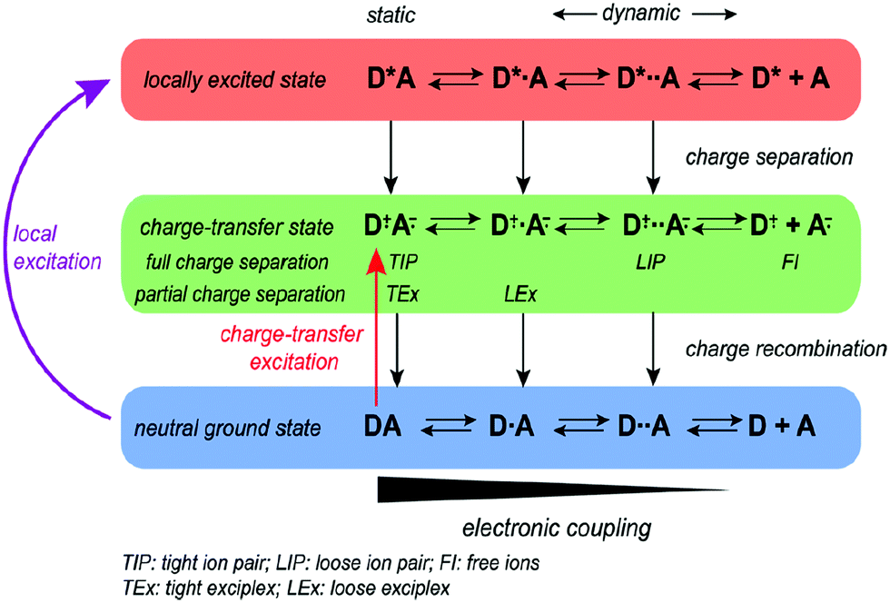
In photoexcitation, Vauthey et al. proposed a bimolecular charge transfer by local excitation and CT excitation in polar solvents (Fig. 2), illustrating the different types of quenching products including tight ion pairs, loose ion pairs, tight exciplexes, loose exciplexes, and free ions that depend on the charge separation (CS) driving force (ΔGCS, the excited reactant was arbitrarily chosen to be the donor).29 For weak to moderate driving forces (ΔGCS ≳ −0.4 eV), the quenching product ranges from exciplexes to loose ion pairs, whereas for large driving forces it varies from tight ion pairs to loose ion pairs. With vanishing coupling, charge transfer emission disappears for ion pairs.6 However, emissive exciplexes and ion pairs can be interconverted under certain conditions.4 For example, no exciplex was observed with the methylperylene/tetracyanoethylene complex because the charge separation is energetically favorable, while a lot of TCNB-based cocrystals gave strong CT emission,30–32 which can be assigned as exciplex emission probably due to the weak to moderate charge separation driving forces.
 | ||
| Fig. 2 Donor and acceptor charge transfer schemes in polar solvents. Reprinted with permission from ref. 29. Copyright 2017 American Chemical Society. | ||
2.2 Electrical excitation generated exciplex
The formation of exciplexes in type II heterojunctions is closely related to the formation of intermolecular CT excitons for nonionic ground state CT complexes.33 Under electrical excitation, holes and electrons are injected into the donor HOMO and the acceptor LUMO from the anode and cathode, respectively. When there is a large energy shift between the LUMOs and HOMOs of the donor and acceptor, these electrons and holes may accumulate at the D/A interface, thereby forming CT excitons between the donor and acceptor molecules34 (Fig. 3). Once the CT excitons have been formed, they may decay to the ground-state through either radiative or nonradiative recombination, depending on the time constant of the processes. Exciplex emission refers to the radiative recombination of CT excitons by radiating photons to release their binding energy (Fig. 3). Generally, exciplexes emit at long wavelengths with broadband spectra because the energies of CT excitons are usually small with many CT state configurations due to the structural and energetic disorder of the donor and acceptor.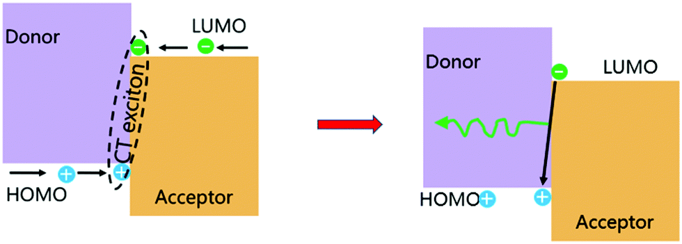 | ||
| Fig. 3 Formation of a CT exciton under electrical excitation and its emission. Reprinted with permission from ref. 34. Copyright © 2017, Science China Press and Springer-Verlag GmbH Germany, part of Springer Nature. | ||
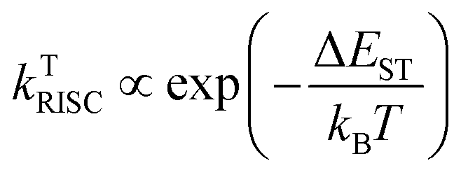
However, the exciplex emits only from the radiative recombination of the singlet CT exciton, and therefore generally exhibits low photoluminescence efficiency.35 Fortunately, in some exciplexes due to the large distance between electrons and hole states, it can be proved that a CT exciton has a very small singlet–triplet energy splitting (EST), which can change the exciton from the non-radiative triplet states to radiative singlet states by reverse intersystem-crossing (RISC).16,36,37 Therefore, the emission of exciplex exhibits the characteristics of TADF, which can capture singlet and triplet excitons through rapid and delayed fluorescence decay channels.
TADF breaks the limit of 25% internal quantum efficiency (IQE) of singlet excitons of radiation species without heavy atoms at room temperature, making the theoretical limit of singlet excitons generated by polarons reach 100%. In theory, when the energy difference EST between the lowest singlet state and the lowest triplet state is sufficiently small, the RISC process can be effectively activated and the IQE can be improved, which can be expressed as
| ΔEST = ES − ET = 2J |
where kB is the Boltzmann constant and T is the temperature.
The luminescence mechanism of the exciplex TADF material is shown in Fig. 4. After the recombination of electrons and holes, singlet and triplet excitons are formed in a ratio of 1![[thin space (1/6-em)]](https://www.rsc.org/images/entities/char_2009.gif) :3; among them, the high exciton state is converted to the lowest exciton state (S1 or T1) through internal conversion (IC), and the triplet excitons accumulated at T1 are transferred back to S1 through the RISC process under thermal activation to form singlet excitons. The singlet excitons at S1 formed by electro-induced excitation or reverse transfer from T1 are deactivated to the ground state (S0) in different ways. For the radiation transition, there are two luminescence processes with different fluorescence lifetimes: prompt fluorescence (PF) and delayed fluorescence (DF), which are caused by RISC. T1 states are radiatively deactivated to S0 through phosphorescence emission. In addition, the energy loss caused by non-radiative (NR) transitions is inevitable during the whole process.40
:3; among them, the high exciton state is converted to the lowest exciton state (S1 or T1) through internal conversion (IC), and the triplet excitons accumulated at T1 are transferred back to S1 through the RISC process under thermal activation to form singlet excitons. The singlet excitons at S1 formed by electro-induced excitation or reverse transfer from T1 are deactivated to the ground state (S0) in different ways. For the radiation transition, there are two luminescence processes with different fluorescence lifetimes: prompt fluorescence (PF) and delayed fluorescence (DF), which are caused by RISC. T1 states are radiatively deactivated to S0 through phosphorescence emission. In addition, the energy loss caused by non-radiative (NR) transitions is inevitable during the whole process.40
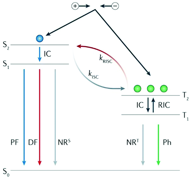 | ||
| Fig. 4 Exciplex TADF luminescence mechanism. ISC, intersystem crossing; kISC, the rate constant of ISC; kRISC, the rate constant of endothermic RISC; NRS, singlet nonradiative decay; NRT, triplet nonradiative decay; and RIC, reverse internal conversion. Reprinted with permission from ref. 40. Copyright © 2018, Macmillan Publishers Limited. | ||
3. Organic emissive exciplex materials
In this section, we will mainly introduce the various organic exciplex materials in terms of donor–acceptor contacting modes (cocrystals, interface, blend, porous coordination, and space-limitation) and their potential application in optoelectronic devices.3.1 Cocrystal emission
The optoelectronic properties of cocrystal molecules are not only affected by non-covalent bonds such as π–π and hydrogen bonds, but also determined by the intermolecular CT interaction, which allows a cocrystal to achieve exciplex emission and other functional properties through synergistic and collective effects.41–44The electron cloud is rearranged on the entire supramolecular structure and new cocrystal molecular orbitals (MO) will be formed when an organic CT cocrystal is obtained. Therefore, the exciplex luminescence characteristics will be changed accordingly. The transition of the luminescence behavior in an organic cocrystal includes luminescence color, luminescence lifetime, photoluminescence quantum yield (PLQY), radiation transition constant (kf), etc. The target color in practical application can be achieved by reasonable selection of the donor or acceptor. He et al. chose 1,2,4,5-tetracyanobenzene (TCNB) as the acceptor molecule, and 3-(naphthalene-2-yl)-2-(p-tolyl)acrylonitrile (NPA), 3-(anthracene-9-yl)-2-phenylacrylonitrile (APA) and 2-(4-methoxyphenyl)-3-(pyrene-1-yl) acrylonitrile (MPA) as donors to construct IA, IIA and IIIA cocrystals, respectively (Fig. 5a). The strong CT, π–π interaction and hydrogen bonding drive two different mixed stacking arrangements (complex IA: DA–DA–DA, IIA and IIIA: DAD–DAD), and at the same time, the ionization potentials of the donor multi-ring parts are different, which have a certain impact on the luminescence color and PLQY of the cocrystal. These three cocrystal systems realize the adjustment from light green emission to dark red emission, the PLQY of IIA is as high as 20.54% with a lifetime of 12.2 ns, which shows excellent optical properties compared to single-component crystals (Fig. 5b).45
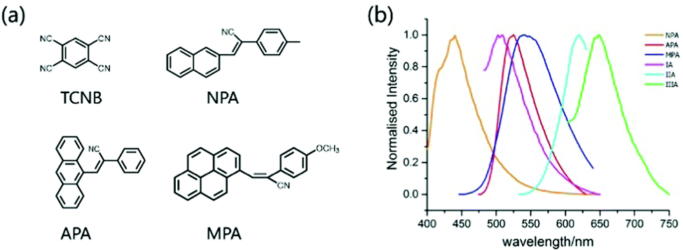 | ||
| Fig. 5 (a) Structures of the acceptor TCNB and donors NPA, APA, and MPA. (b) Fluorescence spectra of donor and CT crystals (λex = 385 nm). Reprinted with permission from ref. 45. Copyright 2018 American Chemical Society. | ||
In addition to the adjustment of monochromatic light in the donor–acceptor cocrystal system, the white light emission (WLE) is pursued due to its potential applications in the field of display and lighting equipment. Hisaeda et al. prepared three-, four-, and five-component cocrystals to tune the luminescence of organic materials, among which a variety of small aromatic molecules were selected as guests and N,N′-dipyrid-3-yl-1,4,5,8-naphthalenediimide (NDI) and tris(pentafluorophenyl)borane (TPFB) were chosen as a supramolecular-host (Fig. 6a and b). In the cocrystal system, these 28 different cocrystal combinations achieve almost full visible light wavelength emission under the intermolecular CT interaction (Fig. 6c). It is worth mentioning that this type of multi-component cocrystal system not only gives monochromatic light emission with a PLQY of 28.3%, but also exhibits high performance WLE with a PLQY of 25.3%. The luminescence lifetime and radiation constant (kf) are also of great significance for multifunctional materials. From the three-component cocrystal system, the fluorescence lifetime and kf are significantly changed compared to the raw materials, and the lifetime can be extended to 24.9 ns.46 In addition, “doping” strategies are commonly used to adjust the emission properties of the cocrystals. A dopant with similar lattice parameters as one of the components of the cocrystal can be selected to be doped into the cocrystal to form a solid solution, and the desired emission color can be customized by adjusting the dopant concentration in the effective Förster resonance energy transfer (FRET) process.47 For example, Liao and coworkers used pyrene as the dopant to prepare (pyrene)x(naphthalene)1−x(TCNB). Due to the doping of pyrene, long-wavelength emission light appeared, which combined with original cocrystal luminescence to produce WLE (Fig. 6d).48 Similarly, Hu and coworkers explored the rational design of polychromatic cocrystals based on the competition between arene–perfluoroarene (AP) and CT interaction. In short, pyrene–octafluoronaphthalene (pyrene–OFN) assembled by AP interaction and pyrene–TCNB formed by CT interaction have different optical properties, but the emission spectrum of the former has a good overlap with the absorption spectrum of the latter. Therefore, after TCNB molecules are incorporated into pyrene–OFN, pyrene–TCNB can reabsorb the emission energy of pyrene–OFN. Due to the competitive intermolecular interaction between the energy donor (pyrene–OFN) and the acceptor (pyrene–TCNB), the hybrid CT complex can effectively afford WLE (Fig. 6e).49
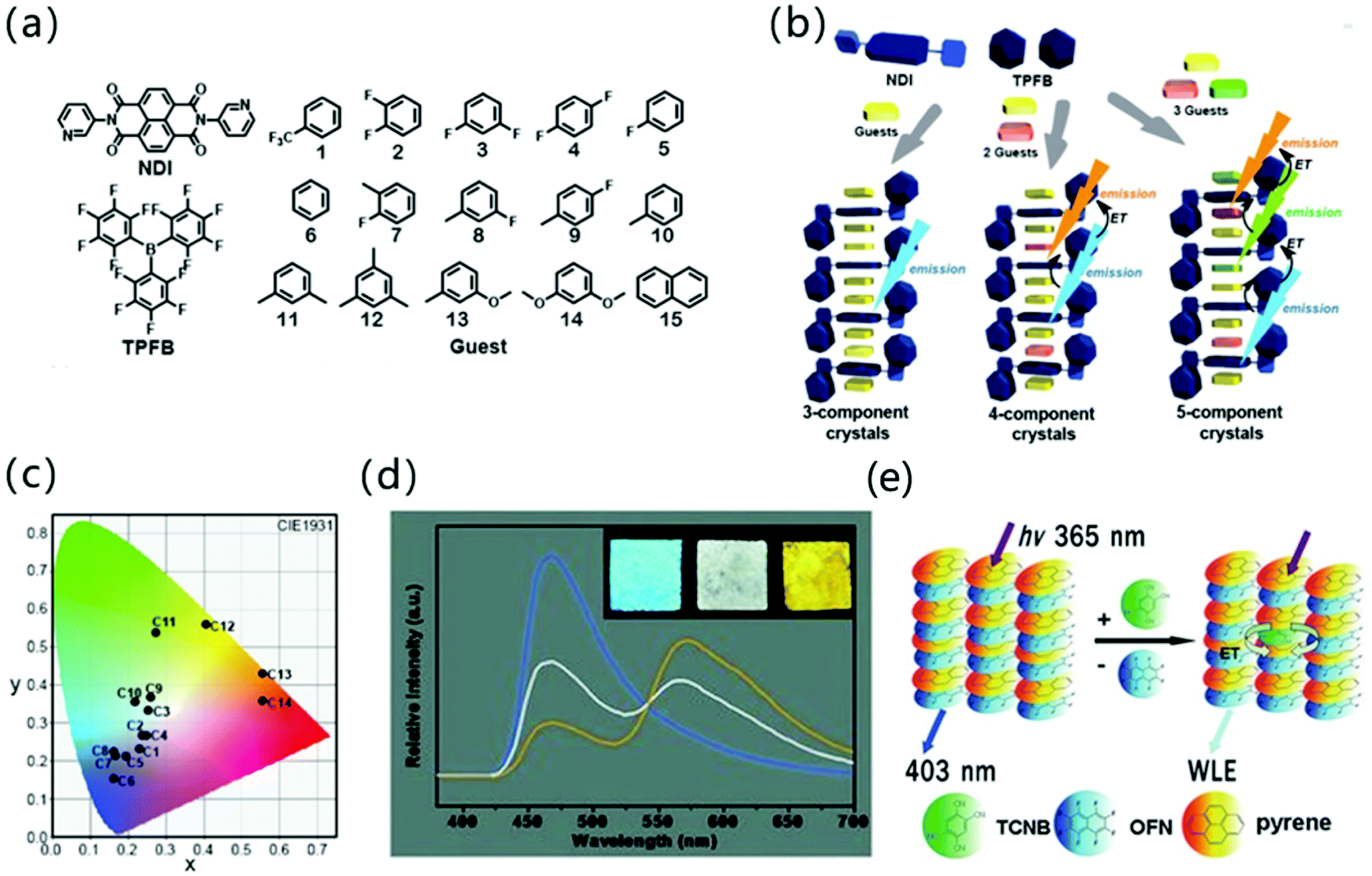 | ||
| Fig. 6 (a) The structure of NDI, TPFB and aromatic guests composed of three, four, and five-component cocrystals. (b) Schematic illustration of three-, four-, and five-component crystalline materials. (c) Emission colors in the CIE 1931chromaticity diagram of multi-component cocrystals. Reprinted with permission from ref. 46. Copyright 2019. The Royal Society of Chemistry. (d) Steady state emission spectra of mixed CT complex microtube films spin-coated on a quartz substrate at doping concentrations of 0 (blue), 0.015% (white), and 0.1% (orange) upon excitation with 365 nm. Insets show the corresponding photographs excited with a UV lamp (365 nm). The excitation wavelength is 365 nm. Reprinted with permission from ref. 48. Copyright © 2012 Wiley-VCH Verlag GmbH & Co. KGaA, Weinheim. (e) The energy transfer mechanism of pyrene–OFN and pyrene–TCNB. Reprinted with permission from ref. 49. Copyright © 2017 Wiley-VCH Verlag GmbH & Co. KGaA, Weinheim. | ||
Organic optical waveguide materials are attracting growing interest because they can be employed as active optical waveguide resonators and effectively confine, propagate, and couple light in the waveguide region, which helps to create a new height for organic optoelectronic functional materials in the next generation of telecommunications technology.50–52 CT complexes play an important role in studying the physical properties along the isotropic/anisotropic molecular stacking direction, because CT interactions and other non-covalent bonds can guide the complexes to form more regular shapes.53 For example, 1,2-di(4-pyridyl)ethylene (trans-Bpe) and TCNB formed two-dimensional parallelogram BTC cocrystals through CT, π–π, and N⋯H–C as the driving forces.54 Moreover, the BTC cocrystal displayed a PLQY of 19% due to the intermolecular CT interaction, exhibiting isotropic optical waveguide characteristics. The optical propagation loss coefficient (R) in the two directions is almost the same, which shows that the optical transmission and molecular accumulation structure in the cocrystal have no contact (Fig. 7a).
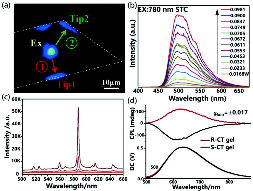 | ||
| Fig. 7 (a) PL microscopy image of BTC under excitation. Reprinted with permission from ref. 54. Copyright © 2015 Wiley-VCH Verlag GmbH & Co. KGaA, Weinheim. (b) The up-conversion PL spectra of STC cocrystals. Reprinted with permission from ref. 55. Copyright © 2017 Wiley-VCH Verlag GmbH & Co. KGaA, Weinheim. (c) PL spectra of CBP@TCNB (1:1) as a function of the pump laser energy. Reprinted with permission from ref. 56. Copyright © 2018, American Chemical Society. (d) Circularly polarized luminescence spectra of a cast film of R-Py/TCNB CT complexes excited by 360 nm. Reprinted with permission from ref. 57. Copyright © 2019 Wiley-VCH Verlag GmbH & Co. KGaA, Weinheim. | ||
Nonlinear optical functional materials can be achieved by manipulating the cocrystallization strategy. Sun et al. used supramolecular self-assembly to prepare the cocrystals STC of 4-styrylpyridine and TCNB.55 In the STC cocrystal, the D–A and π–π interactions of the donor and acceptor are alternately arranged along the a-axis to form a D–π–A spatial network, which effectively promotes intermolecular CT and exhibits excellent electronic coupling. Interestingly, when the STC cocrystal was excited by a laser at 780 nm, the up-conversion produced emission at 500 nm and the material exhibited obvious two-photon absorption characteristics as the incident laser energy continued to increase. The STC cocrystal exhibits unique two-photon absorption properties compared with constituent units, which demonstrates that the two-photon absorption properties are derived from the intermolecular CT interaction in the D–A system (Fig. 7b).
Cocrystals based on intermolecular CT interaction is also a potential material for the preparation of organic lasers. Fang and coworkers reported that the cocrystallization of 4,4′-bis(N-carbazolyl)-1,1′-biphenyl (CBP) and TCNB with different ratios (1:1 and 1:2) can cause different CT interactions and π–π effects, which further result in amplified spontaneous emission and adjustable fluorescence.56 As shown in the Fig. 7c, a slice of the crystalline sample CBP@TCNB (1:1) was excited with a pulsed laser, and the full width at half maximum (FWHM) at the strongest peak dramatically decreased to 2.65 nm with the pump density increased. The integrated intensity at the strongest peak as a function of pump density clearly showed a threshold of 44 mW cm−2, suggesting the potential use of CT complexes in organic lasers.
Due to the large magnetic dipole transition moment in the CT state, the chiral CT system composed of a chiral electron donor and an achiral electron acceptor shows bright circularly polarized emission with a large asymmetry factor, boosting the development of highly efficient circularly polarized luminescence active materials. Recently, Duan et al. used a chiral emissive donor molecule based on pyrene (R/S-Py) with an axial chirality biphenyl group to form mixed-stack CT complexes with several kinds of achiral electron acceptors, including TCNB, tetrafluoro-p-benzoquinone (TFQ), tetracyanoethylene (TCNE) and TCNQ.57 Due to the large energy gap between the donor and acceptor, the CT complex R-Py/TCNB showed strong luminescence and bright circular polarization emission with a dissymmetry factor (glum) as high as 0.017 (Fig. 7d).
There is a class of D–A cocrystal compounds that show not only ambipolar charge transport but also characteristic CT luminescence,58 which can be used in organic light-emitting transistors (OLETs).59 Park et al. used 4M-DSB and CN-TFPA as donors and acceptors respectively to prepare CT cocrystals (Fig. 8a). The solution-processed OFETs based on the cocrystal have ambipolar carrier transport behavior, with hole and electron mobilities of 6.7 × 10⁻³ and 6.7 × 10⁻² cm2 V−1 s−1 respectively. Moreover, the unique CT characteristics produce a strong red-shifted absorption band, which can emit bright red emission light (PLQY: 31%).60 Later, quantum mechanics/molecular mechanics was used to conduct theoretical research on the cocrystal luminescence, and it was concluded that the molecular configuration, the stacking of crystals and the quality of the sample have a certain influence on the improvement of PLQY.61 In order to realize OLET, higher PLQY and more balanced ambipolarity are indispensable. Therefore, Park et al. modified the acceptor (CN-TFPA) and donor (2MDCS) group to prepare a 2D CT cocrystal (Fig. 8a), which not only provided uniform channel coverage with reduced grain boundaries but also afforded uniform interfaces between active layer/dielectric and the active layer/electrodes. The bottom-contact OLET device (Fig. 8b) based on the 2D CT cocrystal not only showed a relatively balanced ambipolar charge transport (μh and μe of ≈10−4 cm2 V−1 s−1) but also exhibited good electroluminescence characteristics (Fig. 8b and c), which opens the door to the development of high-efficiency OLET.62
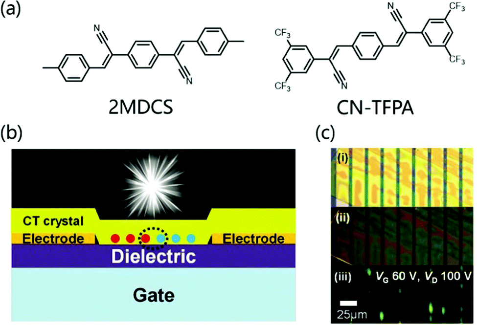 | ||
| Fig. 8 (a) Molecular structure of donor 4MDSB, 2MDCS and acceptor CN-TFPA. (b) Schematic illustration for the bottom-contact SC-OLET device. (c) Images of a device; taken by optical microscopy under white light irradiation (i) and UV irradiation (ii). (iii) was captured during device operation (constant bias condition, VG: 60 V, VD: 100 V). Reprinted with permission from ref. 62. Copyright © 2017 Wiley-VCH Verlag GmbH & Co. KGaA, Weinheim. | ||
Cocrystal engineering provides a facile route to realized exciplex emission for optoelectronic devices with definite packing structures. Different D–A systems have been developed to afford a variety of optical properties in optical waveguides, tunable luminescence and lasers.63,64 However, to date, cocrystal materials with a high PLQY and controllable self-assembly process are still very rare. For long-term practical applications, the mechanism of cocrystallization should be elucidated deeply to develop low-cost, large-scale, highly ordered arrays or thin films for optoelectronic applications.41,65,66 In addition, it is important to further expand the application possibilities of cocrystals in other optical fields (such as electrically pumped organic lasers67 or quantum-well based devices68) as well as multifunctional devices.69
3.2 Interface emission
The heterojunction between two different organic films is the key to promoting the formation of excitons for thin film light-emitting diodes. At the type II P/N organic/organic heterojunction interface between the donor and the acceptor, there is a high tendency to form an exciplex.70,71 The HOMO and LUMO energy levels of the hole transport materials and the electron transport materials show obvious gaps at the heterojunction interface. It is hardly possible to generate an exciton on either component molecule. In contrast, exciplex formation is energetically allowed, in which one of them locates in the excited state while another one is in the ground state being coupled (Fig. 9a). From an electronic point of view, Ng et al. proved that the local charge interaction and interface energy at the organic P/N heterojunction have an important influence on the formation of exciplexes.12,13 Normally, p-type materials are used as electron donors to provide charge to n-type materials to form CT complexes in the Pδ+–Nδ− configuration. However, there is also a process of opposite charge transfer in organic heterojunctions, that is, an n-type material provides electrons to the LUMO energy level of the p-type material at the interface. The formed bound fixed charge ensures the formation of an exciplex, which verifies that the formation of a Pδ−–Nδ+ CT complex is closely related to the emission of an exciplex in an OLED (Fig. 9b).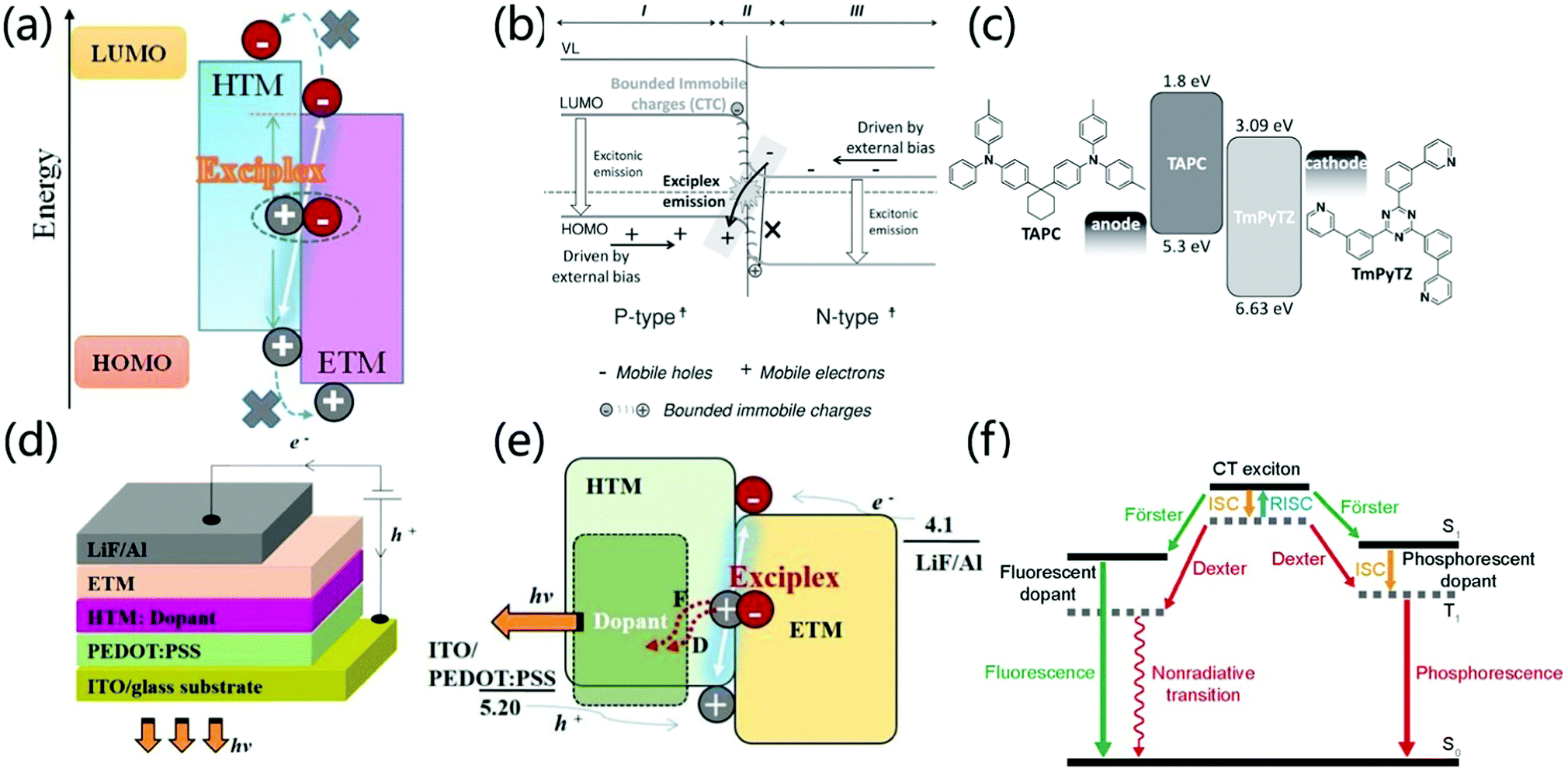 | ||
| Fig. 9 (a) The formation process of an interface exciplex. Reprinted with permission from ref. 71. Copyright 2019 Frontiers Media S.A. (b) The emission mechanism at the interface of type Pδ−–Nδ+ heterojunction. Reprinted with permission from ref. 13. Copyright © 2014 Wiley-VCH Verlag GmbH & Co. KGaA, Weinheim. (c) The device structure of the fluorescent planar p–n heterojunction OLED and the molecular structure and energy level of the p-type hole transport material TAPC and the n-type electron transport material TmPyTZ. Reprinted with permission from ref. 72. Copyright © 2015 Wiley-VCH Verlag GmbH & Co. KGaA, Weinheim. (d) OLED device structure with an exciplex as the host. (e) Energy transfer mechanism when an exciplex is the host. Reprinted with permission from ref. 75. Copyright © 2017 Elsevier B.V. All rights reserved. (f) Light emitting mechanism when an exciplex is used as the host. Reprinted with permission from ref. 34. Copyright © 2017, Science China Press and Springer-Verlag GmbH Germany, part of Springer Nature. | ||
In recent years, scientists have discovered that the exciplex formed at the interface of a heterojunction has the potential for efficient direct emission. For example, Chen et al. reported that high-efficiency interfacial exciplex emission was achieved by using 1,1-bis [4-[N,N-di(p-tolyl)-amino]phenyl]cyclohexane (TAPC) as a p-type semiconductor and 2,4,6-tris(3-(pyridin-3-yl) phenyl)-1,3,5-triazine (TmPyTZ) as an n-type semiconductor (Fig. 9c). By adjusting the thickness of the hole transport layer, a high-performance OLED device with a simple structure, extremely low driving voltage (2.14 V) and high EQE (12.02%) is obtained. The low driving voltage of the P–N heterojunction OLED can be attributed to the fact that carrier trapping, exciton generation, and carrier transport in this region do not encounter a layer-to-layer energy barrier.72 Moreover, due to the good charge transport characteristics of p-type and n-type materials, the thickness of the carrier transport layer will not significantly affect the injection current flux under low driving voltage in a wide range. At the same time, the 12.02% EQE is much higher than the EQE limit (5%) of traditional singlet OLEDs due to the fact that an interface-formed exciplex has a smaller EST and formation of TADF emission.73 Therefore, the interface exciplex provides a new strategy for the preparation of light-emitting devices with high performance, low driving voltage and simple structure. The formation of exciplexes can modulate the luminescent color of OLEDs devices. Date et al. synthesized the TADF emitter POZ-DBPHZ based on U-shaped D–A–D architecture.74 OLEDs fabricated with POZ-DBPHZ exhibit orange-yellow light emission and achieved excellent efficiencies up to 16% EQE. However, the interface exciplex formed by POZ-DBPHZ and m-MTDATA showed deep-red emission (lem = 741 nm) and exhibited an EQE of ∼5%, which is an excellent value for a TADF deep-red OLED. Although the overall performances were much smaller than those of CT-based TADF devices, the exciplex emitters would open possibilities to tune the luminescent color of the device.
In addition to direct light emission, the exciplex system can also be used as a host for luminophores through the Förster or Dexter process by dopants, forming the electron transport layer or hole transport layer (Fig. 9d and e), which provides another strategy to prepare high-performance light-emitting devices.71,75 For phosphorescent dopants, CT excitons transfer energy to the dopant through the Förster and Dexter processes. After that, the singlet excitons on the dopant are quickly converted into triplet excitons through effective intersystem crossing (ISC). Therefore, both singlet and triplet excitons in the interface exciplex can excite the phosphorescent dopant, which makes the internal quantum efficiency of the exciplex as high as 100%. Zhang et al. used m-MTDATA and 1,3,5-tri(m-pyrid-3-yl-phenyl)benzene (TmPyPB) as interface exciplexes and Ir(Flpy-CF3)3 as a phosphorescent dopant to achieve high performance devices with an EQE of 25.2%, power efficiency of 97.2 lm W−1, and low driving voltage of 2.60 V at 100 cd m−2.76 However, in the case of fluorescent dopants, both Dexter and Förster energy transfer processes occur but only singlet emission from the fluorescent dopant is possible (Fig. 9f).34 Komatsu et al. prepared a fluorescent-doped OLED based on interface emission, the structure of which is [ITO (130 nm)/PEDOT:PSS (30 nm)/4CzIPN 5 wt% doped 4,4′-N,N′-dicarbazolylbiphenyl (CBP) (35 nm)/bis-4,6-(3,5-di-4-pyridylphenyl)-2-methylpyrimidine (B4PyMPM) (65 nm)/8-quinolinolato lithium (Liq) (3 nm)/Al (100 nm)]. This device exhibits a high fluorescence emission EQEmax of 16%, a very low turn-on voltage of 2.5 V at 1 cd m−2 and a maximum power efficiency of over 55 lm W−1.77 Therefore, the doping of interface exciplexes provides an effective strategy for the preparation of high-performance, low-drive voltage light-emitting devices.
Compared to other host strategies in OLED, an interfacial exciplex provides a barrier-free charge injection, unimpeded charge transport, tailorable singlet/triplet exciton populations, and an energy-saving direct exciton formation process at the heterojunction interface region.71 Therefore, simultaneous low voltage, high EQE/PE, low roll-off rate and even much higher device stability were representatively achieved, irrespective of dopant types. It should be noted that RISC up-conversion of the exciplex host renders the interfacial exciplex with an enhanced Förster energy transfer process with low exciton density on emitters, thereby removing the risk of accelerating exciton-aggregation quenching. Furthermore, local high charge/exciton density at the interfacial exciplex region is not a drawback but an advantage that is not accessible in the blend exciplex counterpart. Interfacial exciplex architecture is also an ideal choice to demonstrate a long-ranging coupling property that has not been widely used in host applications.28,78 Compared to a blend exciplex, interfacial exciplex host applications in OLEDs are still limited. It is significant to further utilize the structural advantages of an interfacial exciplex in order to construct high-performance OLEDs and illuminate the related physical processes.
3.3 Blend emission
Blending refers to the preparation of a solid film by mixing the electron donor and the electron acceptor in a certain ratio.79 Such solid thin-film devices usually also exhibit excellent optical properties and tuneable luminescence. In the early years, due to the weak electronic coupling between the excited state and the ground state of a strong charge transfer molecule, the exciplex-based OLED devices prepared by a D–A hybrid solid-state thin film showed lower electrical performance. Palilis et al. reported efficient exciplex emission between N,N-diphenyl-N,N-(2-naphthyl)-(1,1-phenyl)-4,4-diamine (NPB) and 2,5-di-(3-biphenyl)-1,1-dimethyl-3,4-diphenylsilacyclopentadiene (PPSPP) with the PLQY of 62% in the blended film. However, the EQE of the prepared interface exciplex OLED device is only 3.4%, indicating the poor exciton utilization efficiency.10In 2012, Adachi et al. achieved an EQE of 5.4% under the condition of only 26% PLQY in the film prepared by blending m-MTDATA and 3TPYMB, which is attributed to the small singlet and triplet splits.16 The up-conversion caused by small EST effectively solves the low utilization rate of the exciplex. Therefore, in recent years, many efficient blended luminescent materials have been discovered. Liu et al. reported the emission of blue optical exciplexes blended with TAPC and 3-(4,6-diphenyl-1,3,5-triazin-2-yl)-9-phenyl-9H-carbazole(DPTPCz) with its EQE as high as 15.4% (Fig. 10a);80 Lin and his co-workers used CN-Cz2 as the electron donor and PO-T2T as the electron acceptor, which achieves cyan emission with an EQE of 16% (Fig. 10b).81 In 2019, Chapran et al. demonstrated a green TADF emission based on the TSBPA:PO-T2T exciplex with a record high maximum current efficiency of 60.9 (cd A−1), maximum power efficiency of 71 (lm W−1), and EQE of 20%, which is close to the theoretical maximum (Fig. 10c).82
 | ||
| Fig. 10 Example of blending a donor and acceptor to adjust the emission color of OLED. (a) Blue: TAPC:DPTPCz. (b) Cyan: PO-T2T:CN-Cz2. (c) Green: PO-T2T:TSBPA. | ||
Exciplex-based OLEDs formed by blending are a promising way to harvest triplet excitons and improve the luminescence efficiency of OLEDs.83–85 However, some challenges need to be settled. (1) It is highly important to explore more effective co-deposition methods or solution co-assembly techniques to achieve uniform blending of donor and receptor molecules. Whether the blending of a donor and acceptor is thermodynamically stable or not needs to be investigated deeply. (2) To date, few efficient red exciplexes have been reported, posing a serious problem for the possible application in white OLEDs.82 Hence, diversifying the blending exciplex materials with different emission color is pursued for the application in OLEDs.
3.4 Intermolecular CT emission in PCPs
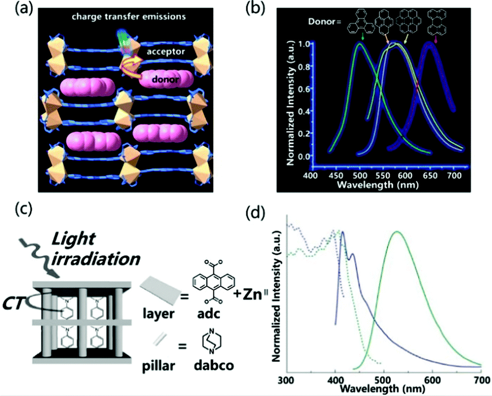
Porous coordination polymers (PCPs) or metal organic frameworks (MOFs) refer to the self-assembly structure of metal ions and organic ligands.86,87 They have the advantages of excellent designability, high crystallinity, inherent porosity and synergistic response.88 Therefore, different functional guests can be introduced into the nanopore to adjust the light-emitting properties of the material. Moreover, the regular and non-aggregating arrangement prevents self-quenching of fluorescence. Based on these advantages, exciplex emission can also be realized between the MOFs material and the introduced guest molecules.The host–guest charge transfer can tune the luminescence properties of materials by choosing different electron-deficient and electron-rich molecules as donors and acceptors. Zhao et al. reported the introduction of different aromatic small molecules into PCPs with 2,4,6-tri(pyridin-4-yl)-1,3,5-triazine (tpt) and 1,4-pda2− as the ligand, and Cd(II) as the metal atom to change the emission color.89 For the structure of luminescent coordination polymers, the backbone of 1,4-pda2− adopts a chair-shape configuration, and the carboxylate groups adopt chelating and chelating–bridging coordination modes to link two crystallographic independent Cd(II) ions to form a binuclear secondary building unit (SBU). Then the SBUs are connected via 1,4-pda2− ligands and tpt to generate bilayer structures. The double-layer pattern adopts the AAA stacking model, and the guest molecules enter the rectangular channel stacked face to face with the acceptor molecules (Fig. 11a). The close packing between the layer and the guest molecules indicates that the π–π interaction between DA molecules is more pronounced, which helps to enhance the luminescence properties of the material. The insertion of small-molecule aromatic derivatives with different ionization potentials tailor the emission from cyan to red light (Fig. 11b). In addition, the introduction of guest molecules can also increase the luminescence efficiency of PCPs materials. Tanaka et al. observed that the distance between the anthracene plane in the multi-vacancy coordination polymer composed of anthracene derivatives and ZnII is 3.75 Å (Fig. 11c), which is too large compared to the π–π effect, so the PLQY of the PCPs structure was measured to be only 0.01%. However, when N,N-dimethylaniline (DMA) as an acceptor was incorporated, the emission wavelength of PCPs was significantly red-shifted and the PLQY rose to 0.13% (Fig. 11d). The absolute value of PLQY is 0.13%, which is more than 10 times larger than the value for PCPs skeleton. In general, the emission efficiency of an exciplex is low because its transition dipole moment is lower than that of fluorescence transition. However, the restricted configuration of DMA in nanopores can improve the exciplex emission efficiency remarkably.90
 | ||
| Fig. 11 (a) Intermolecular CT emission structure composed of PCPs and aromatic derivatives. (b) Normalized emission spectra of doped different guests excited at 370 nm. Reprinted with permission from ref. 89. Copyright © 2017, American Chemical Society. (c) Schematic illustration of host–guest CT interaction in excited states. (d) Excitation (dashed line) and emission (solid line) spectra of PCPs (blue) and DMA inserted into PCPs (green). The excitation wavelengths are 376 nm and 410 nm, respectively. Reprinted with permission from ref. 90. Copyright 2007 The Royal Society of Chemistry. | ||
Exciplex emission from both local and CT excitation can be realized in PCPs at the same time. According to the work reported by Kitagawa et al., in PCPs the emission nature was identified due to the different conformations adopted by aromatic guests in the different adsorption sites of the PCPs (called pore A and pore B) (Fig. 12a). Site A is a slit-like pore in which the face-to-face configuration (overlap) between the aromatic guest molecule and the electron acceptor allows for effective orbital overlap, providing a higher covalent contribution in the excited state. On the contrary, site B is an undulating one-dimensional channel where small aromatic donor molecules are not restricted in the structure, and the NDI-guest complex will show purer ionic characteristics. Fig. 12c illustrates all the luminescence forms that exist in the PCPs system, including the self-emission of the excited acceptor molecules (τ1), the emission of the PCPs skeleton (τ2), the emission of exciplexes (τ3) and charge transfer recombination of the emission of objects (τ4). Among them, the fluorescence lifetime of the exciplex is linearly related to the dipole moment of the guest, and the lifetime of the ionic ground state CT complex is related to the ionization potential of the guest (Fig. 12b). Compared with the exciplex emission by local excitation, the CT excitation led to more ionic properties with longer lifetimes, and red-shifted and lower efficiency fluorescence bands, which are promoted as the dipole moment and/or electron-donating capacity of the guests increase. In extreme cases, the ionic ground state CT complex supports the entire electron transfer process, and fluorescence will be quenched by conversion to radical ion pairs.91 These detailed theoretical results are helpful to fully understand the regulation of the intermolecular CT effect on the luminescence properties in PCPs.
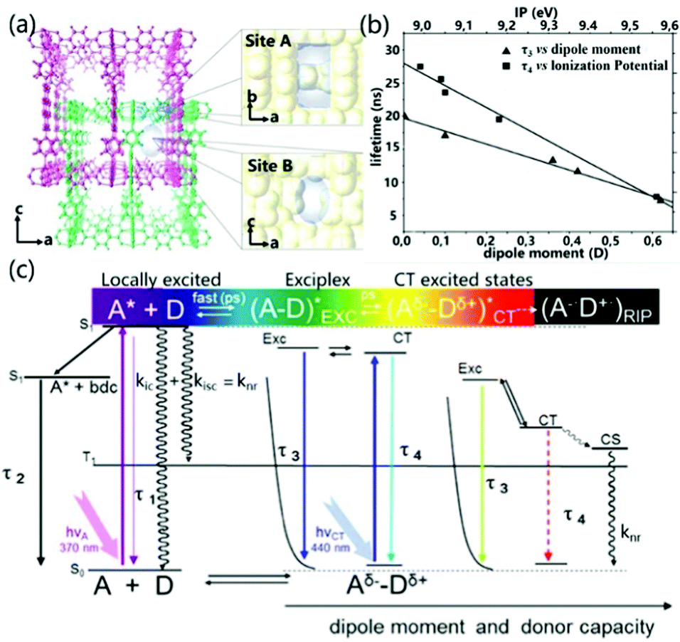 | ||
| Fig. 12 (a) Schematic diagram of the structure of site A and site B. (b) Linear correlation of the exciplex lifetime (τ3) with the dipole moment and CT complex lifetime (τ4) with the ionization potential (eV) of the aromatic guests. (c) Energy level diagram of all the emissive species and processes in PCP. Definitions: τ1, deactivation of NDI (A); τ2, deactivation of the interframework complex NDI–bdc (benzenedicarboxilate); τ3, deactivation of the exciplex NDI–aromatic guest; τ4, deactivation of the CT complex; LE, locally excited; EXC, exciplex (dissociative in the ground state); CT, charge transfer; CS, charge separation; RIP, radical ion pair. Reprinted with permission from ref. 91. Copyright © 2012, American Chemical Society. | ||
The ordered nature of PCP structures can be used as an ideal platform to study the photophysical mechanism of exciplex formation and emission.92 In PCPs, the exciplex can be arranged in a regular and fixed manner, preventing aggregation-caused quenching of fluorescence, which helps to achieve fine-tuned luminescence of the exciplex.91,93 However, the difficult determination of the conformation and the complicated synthetic process have led to the lack of high PLQY luminescent exciplexes in PCPs to date.
3.5 Single component CT complex emission
Single component charge transfer complexes (SCCTC) can be defined as different parts of the same molecule acting as D and A, respectively, and electronically interacting with the A and D groups of adjacent molecules, which have potential applications in single-component white light emission,94,95 room temperature phosphorescence,96 and nonlinear optics.97In 2014, Jin et al. reported for the first time a pyridinium salt (L-Cl·ClO4) with the same intermolecular CT interaction (Fig. 13a), which can emit strong white light in a solid state. The WLE originated from the combination of an additional exciplex emission and the unquenched high-energy monomer emission (Fig. 13b). Interestingly, when excited at 360 nm, the crystal showed almost pure WLE with CIE coordinates of (0.32, 0.33), and the quantum yield is 12%.94 Similarly, Xie and co-workers revealed the dual emission characteristics of asymmetrical diphenylketone and diphenylsulfone derivatives. The dual emission characteristics are ascribed to the balance between intermolecular CT and intramolecular CT, which is importantly related to intermolecular C–H⋯O hydrogen bonds (Fig. 13c). Tailorable multicolor luminescence (including pure WLE) was controlled by hydrogen bonding, which was demonstrated by adding a methanol solution breaking intermolecular hydrogen bonds in the CPzPO system (Fig. 13d). With an increase in the amount of methanol, the CPzPO system displayed alterable luminescence color from low-energy WLE (0.28, 0.33) to high-energy blue light emission (0.20, 0.26). When the temperature was lowered, the sample showed a stronger prompt fluorescence component, while the delayed fluorescence component can be ignored, which is consistent with the TADF characteristics (Fig. 13e). Based on the improvement of the exciton utilization efficiency due to the TADF characteristics, 36.1% PLQY was obtained at room temperature for the CPzPO crystal (medium is benzene), which greatly promoted the study of the luminescence performance of SCCTC materials.95
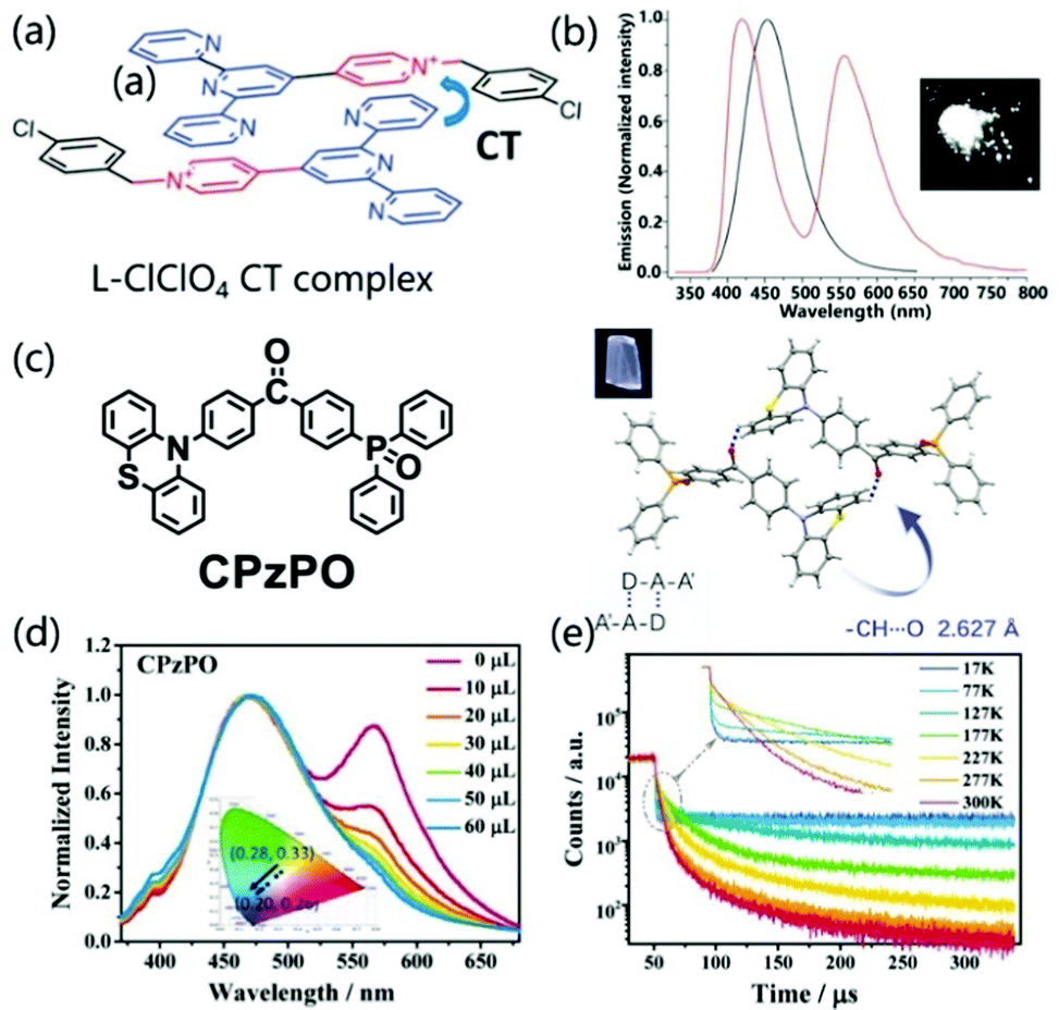 | ||
| Fig. 13 (a) Structure of L-Cl·ClO4 and the presentation of the formation of a CT complex. (b) Fluorescence spectra of L-Cl·ClO4 in dilute EtOH solution (10−5 M) (black line) and the crystalline state (red line) (excited at 290 nm). Photographs of L-Cl·ClO4 crystals were taken under 365 nm UV light. Reprinted with permission from ref. 94. Copyright 2014 The Royal Society of Chemistry. (c) The chemical structures, single-crystal structures, and luminescence pictures of CPzPO. (d) Changes in the emission spectra and CIE coordinates of CPzPO by gradual addition of methanol in benzene solution. (e) Temperature-dependent emission decay spectra of CPzPO at 564 nm in the crystalline state. Reprinted with permission from ref. 95. Copyright © 2017 Wiley-VCH Verlag GmbH & Co. KGaA, Weinheim. | ||
In SCCTC, orange-red phosphorescence limited to metal-based systems previously was obtained from pure organic systems. Ray et al. designed SCCTC based on phenoxazine–quinoline conjugates (Fig. 14a), where the phenoxazine ring was covalently attached to the quinoline fragment through a C–N bond. In this system, taking PQ3 as an example, as the concentration increased from 0.1 μM to 1.0 mM in a deoxygenated solution, the emission intensity increased significantly. In addition, the lifetime was 72.2 μs and there was no fast emission part from the transient analysis of phosphorescence decay (Fig. 14b). These results clearly suggested that SCCTC exhibited effective room temperature red phosphorescence through a high concentration of I2CT. At the same time, the ΔEST of PQ12, PQ22 or PQ32(dimer) is calculated to be as small as 0.05, 0.14 or 0.09 eV, respectively. These lower EST values can achieve an efficient ISC process, thereby increasing the room temperature orange-red phosphorescence efficiency. The measured absolute quantum efficiencies were 19.6%, 38.2%, and 6.1% for PQ12, PQ22 and PQ32 respectively, which were relatively higher than the literature values.96,98
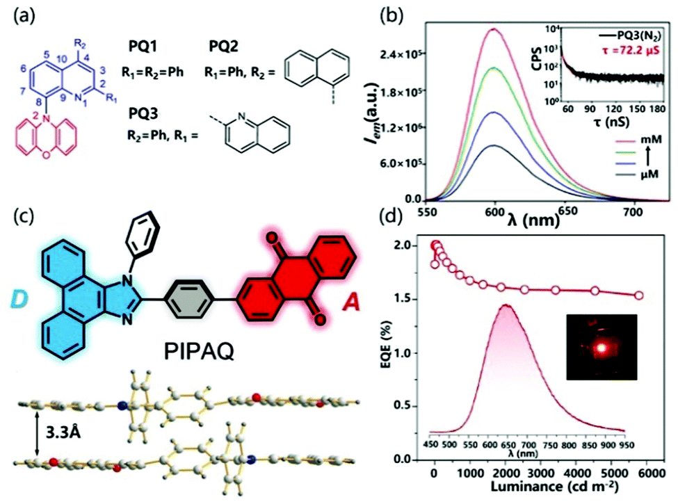 | ||
| Fig. 14 (a) Structure of PQ1, PQ2 and PQ3. (b) Emission spectra of PQ3. Reprinted with permission from ref. 96. Copyright © 2018, American Chemical Society. (c) Structure of PIPAQ and dimer. (d) EQE–luminance curve of an OLED based on PIPAQ (inset: EL spectrum and a photograph of an operating device). Reprinted with permission from ref. 99. Copyright © 2019 Wiley-VCH Verlag GmbH & Co. KGaA, Weinheim. | ||
The formation of SCCTC requires a specific spatial arrangement of two interacting molecules. In an amorphous film, the number of molecular pairs meeting this spatial arrangement will be greatly reduced, which limits the preparation of OLED devices based on SCCTC. Fortunately, Chen et al. demonstrated SCCTC thermally activated delayed fluorescence in the deep red/near infrared region (NIR) and its application in organic electroluminescence. The intramolecular charge transfer molecule 2-(4-(1-phenyl-1H-phenanthro[9,10-d]imidazol-2-yl)phenyl) anthracene-9,10-dione (PIPAQ; Fig. 14c) was designed and synthesized with yellow emission of TADF in the monomer state. Unlike the conventional twisted monomolecular structure with TADF characteristics, PIPAQ is almost a planar molecule. Moreover, PIPAQ molecules have a strong tendency to form cofacial head-to-tail dimers through the intermolecular D–A interaction (Fig. 14d), which enables PIPAQ to retain its SCCTC characteristics after forming an amorphous film, thereby achieving deep red/NIR TADF OLEDs. In this system, not all PIPAQ molecules form SCCTC dimers in the vacuum-deposited emission layer. At the same time, a significant overlap is observed between the absorption spectrum of the film and the PL spectrum of the solution, which indicates that the effective energy transfer is from non-interacting free molecules to SCCTC species. As a result, the SCCTC dimer forms a unique deep red/NIR electroluminescence band. SCCTC OLEDs exhibited an EQE up to 2.10%, with a low roll-off (Fig. 14f). Incredibly, the exciton utilization efficiency close to 100% can be achieved through the triplet trapping capability of the TADF SCCTC emitter.99
Despite interesting photophysical properties, SCCTC emission properties were mostly observed in crystalline samples and rarely found in an amorphous thin film. A head-to-tail donor–acceptor arrangement is an essential prerequisite to achieve efficient exciplex emission, which still remains a long-standing issue to design SCCTCs. Needless to say, the related OLED devices are definitely in the infancy stage, exhibiting a much poorer EQE compared to other TADF systems.
3.6 Through-space charge transfer emission
Thanks to the TADF mechanism and the development of suitable D/A pairs, OLEDs based on exciplexes have reached impressive EQEs exceeding 16% over the past few years.81 Unfortunately, the performance of OLED devices based on exciplexes is still far behind those using traditional conjugated D–π–A TADF materials or phosphorescent emitters.100–103 The distance and orientation between D and A species are an important parameter for exciplex emission. For example, in the D/A mixed dilute solution, the emission of an exciplex is negligible.104 One possible way to solve this challenge is to combine D and A molecules into one molecule through a non-conjugated σ–spacer of variable length to form a donor–σ–acceptor (D–σ–A) structure.105 Recently, it has been found that the space-limited CT of D and A can be realized by selecting rigid connectors, which effectively changes the molecular orientation between D and A and greatly improves the optical properties.106,107The majority of TADF molecular designs utilize a twisted conformational influence of the D and A π systems to minimize the overlap of HOMO and LUMO to improve the luminescence efficiency. However, the rigid backbone firmly places the donor and acceptor in a cofacial arrangement with a specific distance, which can quantitatively form the exciplex structure of charge transfer. Therefore, the space-constrained CT can not only improve the luminescence performance, but also avoid the synthesis barriers of traditional TADF materials. Recently, Liao et al. connected D and A through a rigid skeleton fluorene linker, thereby restricting them to a closely packed nearly coplanar orientation (Fig. 15).
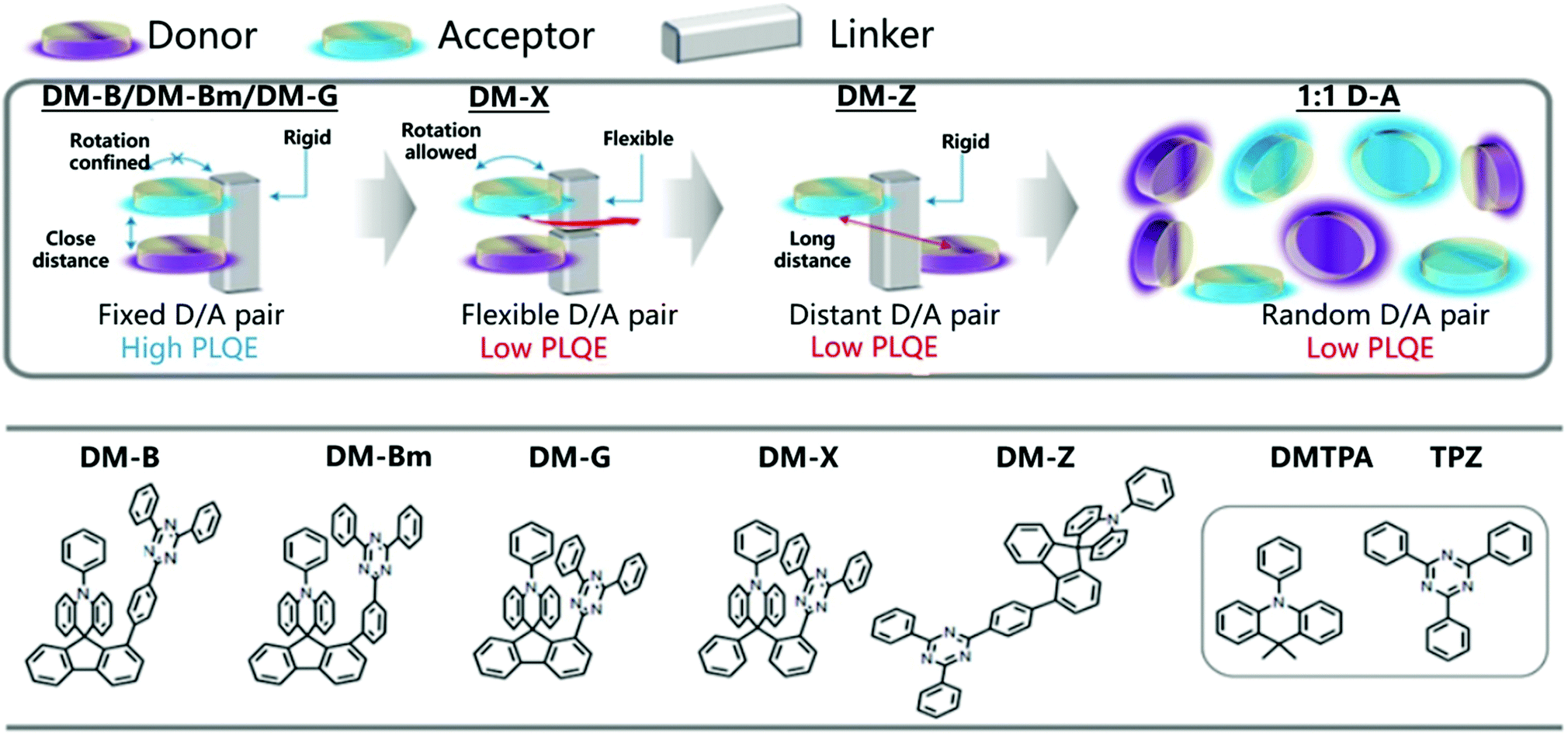 | ||
| Fig. 15 Molecular design model and chemical structures of DM-B, DM-Bm, DM-G, DM-X and DM-Z. Reprinted with permission from ref. 106. Copyright © 2020, The Author(s), under exclusive licence to Springer Nature Limited. | ||
The rigid skeleton is directly connected to the donor through the center of the spiral and has considerable space constraints, which is expected to effectively inhibit intramolecular rotation and vibration.108 As expected, DM-B, DM-Bm, and DM-G showed PLQYs of 96%, 92% and 88% in the film, respectively. An OLED based on DM-B reached an EQE of 27.4% at 67 cd m−2 with only minor efficiency roll-off (EQE = 24.4%) at a higher luminous intensity of 1000 cd m−2.106 The precise control of the donor and acceptor conformation can achieve a high exciplex emission quantum yield. The rigid framework enhances the ground state electronic coupling and inhibits the non-radiative decay channel, which helps to expand the scope of the space-constrained CT concept and realize efficient optoelectronic performance.
Interestingly, space charge transfer has been employed in tuning the emission color by connecting different or multiple D/A units in the polymer backbone.109 Wang et al. reported through-space charge-transfer polymers (TSCT polymer) containing a non-conjugated polystyrene backbone and spatially separated acridan donor and triazine acceptor units to achieve solution processing with full color and WLE OLEDs.110 As shown in Fig. 16a, new triazine acceptors with different electron-accepting capabilities are used to regulate the CT intensity between donor and acceptor, which ensures that the polymers show full-color emission from deep blue (455 nm) to red (616 nm). Meanwhile, the TSCT polymers exhibited TADF characteristics with a high PLQY of 6–74% in the solid state and lifetimes of 0.36–1.98 μs for delayed fluorescence. In addition, white light emission was realized by combining different acceptors and donors on the same polymer chain to generate both blue and yellow emission (Fig. 16b). OLED devices based on these polymer materials also exhibited a satisfactory electroluminescence performance with maximum EQEs of 7.1%, 16.2%, 1.0%, and 14.1% for deep blue, green, red, and white emission, respectively.
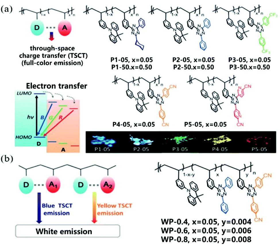 | ||
| Fig. 16 (a) Molecular design and chemical structures of through-space charge-transfer polymers with full-color emission. D donor, A acceptor, B blue, G green, and R red. (b) Molecular design and chemical structures of through-space charge-transfer polymers with white emission. Reprinted with permission from ref. 110. Copyright © 2019 Wiley-VCH Verlag GmbH & Co. KGaA, Weinheim. | ||
The space charge transfer complexes not only break through the ‘intermolecular’ barrier in conventional exciplex emitters through the bridge of a rigid backbone,106,107 but also enable the coverage of the entire visible region emission by modulating the CT interactions between the donors and acceptors on one polymer chain.109 Notably, solution-processed techniques have been employed in OLEDs based on space charge transfer complexes.109 However, there is a long way to go to develop new space charge transfer systems with controllable synthetic methods.111
Conclusions and outlook
In this review, we have discussed the formation mechanism and emission process of exciplexes. We have focused on the donor–acceptor contacting modes, luminescence properties of exciplex materials, and their latest luminescent applications. In spite of many achievements in organic luminescent exciplex materials, there are still several key issues or challenges to be solved in the future.(1) Molecular structures. Choosing a suitable D/A molecule is the prerequisite for realizing multi-functional and efficient exciplex emission. Different molecular structures with varied intermolecular interactions in the exciplex result in an obvious discrepancy in electron–hole wave-function overlap and charge separation driving force, thus influencing exciplex emission properties significantly. Deep understanding of the relationship between molecular structures and exciplex emission will shed light on the rational design of organic exciplexes.
(2) Processing methods. CT interactions both in ground and excited states are controlled by not only molecular structures but also donor–acceptor contacting modes, microstructures and morphologies, which can be controlled by processing methods. Traditional solution or vapor phase methods usually afford small crystals in ∼mm size or polycrystalline thin film with lots of defects, which hinder the further optoelectronic applications. New techniques need to be developed for preparing large area two-dimensional single crystals with preferable donor–acceptor contacting modes, which are important to fabricate high performance optoelectronic devices such as light-emitting diodes or even light-emitting transistors.
(3) Multifunctional properties. Combining luminescence with flexibility, charge transport, stimulus responsivity or other properties into an organic exciplex will enable the fabrication of multifunctional devices. However, how to make an elegant compromise between the luminescence and other functionalities is a big issue for scientists in this field. For example, in virtue of bright luminescence and ambipolar transport in a CT cocrystal, Park et al. demonstrated the first CT electroluminescence in a single active-layered organic light-emitting transistor,62 which is important to simplify the structure of active matrix displays and realize electrically pumped organic lasers.
We anticipate that further advances in organic luminescent exciplex materials will be made toward high-performance and multifunctional optoelectronic devices by the deep collaboration of scientists in the fields of chemistry, material science, and electronics as well as theoretical computation.
Conflicts of interest
There are no conflicts to declare.Acknowledgements
We are grateful for the financial support from the Ministry of Science and Technology of China (Grants 2016YFB0401100 and 2017YFA0204503), the National Natural Science Foundation of China (51822308, 51725304, 21975263, 22171019, 51733004, and 51633006), and the Fundamental Research Funds for the Central Universities (buctrc202103).Notes and references
- T. Mori and Y. Inoue, Chem. Soc. Rev., 2013, 42, 8122–8133 RSC.
- S. A. Jenekhe and J. A. Osaheni, Science, 1994, 265, 765–768 CrossRef CAS PubMed.
- C. Deibel, T. Strobel and V. Dyakonov, Adv. Mater., 2010, 22, 4097–4111 CrossRef CAS PubMed.
- B. Dereka, M. Koch and E. Vauthey, Acc. Chem. Res., 2017, 50, 426–434 CrossRef CAS PubMed.
- X. Y. Zhu, Q. Yang and M. Muntwiler, Acc. Chem. Res., 2009, 42, 1779–1787 CrossRef CAS.
- S. Richert, A. Rosspeintner, S. Landgraf, G. Grampp, E. Vauthey and D. R. Kattnig, J. Am. Chem. Soc., 2013, 135, 15144–15152 CrossRef CAS PubMed.
- H. A. Al Attar and A. P. Monkman, Adv. Mater., 2016, 28, 8014–8020 CrossRef CAS PubMed.
- T. Noda, H. Ogawa and Y. Shirota, Adv. Mater., 1999, 11, 283–285 CrossRef CAS.
- C. Adachi, T. Tsutsui and S. Saito, Appl. Phys. Lett., 1990, 56, 799–801 CrossRef CAS.
- L. C. Palilis, A. J. Makinen, M. Uchida and Z. H. Kafafi, Appl. Phys. Lett., 2003, 82, 2209–2211 CrossRef CAS.
- Y. Sun, N. C. Giebink, H. Kanno, B. Ma, M. E. Thompson and S. R. Forrest, Nature, 2006, 440, 908–912 CrossRef CAS PubMed.
- T.-W. Ng, M.-F. Lo, S.-T. Lee and C.-S. Lee, Org. Electron., 2012, 13, 1641–1645 CrossRef CAS.
- T.-W. Ng, M.-F. Lo, M.-K. Fung, W.-J. Zhang and C.-S. Lee, Adv. Mater., 2014, 26, 5569–5574 CrossRef CAS PubMed.
- C. Gao, W. W. H. Wong, Z. Q. Qin, S.-C. Lo, E. B. Namdas, H. Dong and W. Hu, Adv. Mater., 2021, 33, 2100704 CrossRef CAS PubMed.
- Y.-S. Park, S. Lee, K.-H. Kim, S.-Y. Kim, J.-H. Lee and J.-J. Kim, Adv. Funct. Mater., 2013, 23, 4914–4920 CrossRef CAS.
- K. Goushi, K. Yoshida, K. Sato and C. Adachi, Nat. Photonics, 2012, 6, 253–258 CrossRef CAS.
- H. M. McConnell, B. M. Hoffman and R. M. Metzger, Proc. Natl. Acad. Sci. U. S. A., 1965, 53, 46–50 CrossRef CAS PubMed.
- R. J. Dillon and C. J. Bardeen, J. Phys. Chem. A, 2011, 115, 1627–1633 CrossRef CAS PubMed.
- M. RS, J. Phys. Chem., 1952, 56, 801–822 CrossRef.
- M. Ottolenghi, Acc. Chem. Res., 1973, 6, 153–160 CrossRef CAS.
- C. J. Bender, Chem. Soc. Rev., 1986, 15, 475–502 RSC.
- G. Del Re, P. Olto and J. Ladik, Isr. J. Chem., 1980, 19, 265–271 CrossRef CAS.
- K. Deepthi, IJO-Science, 2017, 3, 43–47 Search PubMed.
- A. Y. Sosorev and D. Y. Paraschuk, Isr. J. Chem., 2014, 54, 650–673 CrossRef CAS.
- S.-J. He and Z.-H. Lu, J. Photonics Energy, 2016, 6, 036001 CrossRef.
- G. L. Ingram and Z.-H. Lu, Org. Electron., 2017, 50, 48–54 CrossRef CAS.
- J. H. Kim, B.-K. An, S.-J. Yoon, S. K. Park, J. E. Kwon, C.-K. Lim and S. Y. Park, Adv. Funct. Mater., 2014, 24, 2746–2753 CrossRef CAS.
- H. A. Al Attar and A. P. Monkman, Adv. Mater., 2016, 28, 8014–8020 CrossRef CAS PubMed.
- B. Dereka, M. Koch and E. Vauthey, Acc. Chem. Res., 2017, 50, 426–434 CrossRef CAS PubMed.
- C. Zhai, X. Yin, S. Niu, M. Yao, S. Hu, J. Dong, Y. Shang, Z. Wang, Q. Li, B. Sundqvist and B. Liu, Nat. Commun., 2021, 12, 4084 CrossRef CAS PubMed.
- J. Wang, S. Zhang, S. Xu, A. Li, B. Li, L. Ye, Y. Geng, Y. Tian and W. Xu, Adv. Opt. Mater., 2019, 8, 1901280 CrossRef.
- L. Sun, W. Hua, Y. Liu, G. Tian, M. Chen, M. Chen, F. Yang, S. Wang, X. Zhang, Y. Luo and W. Hu, Angew. Chem., Int. Ed., 2019, 58, 11311–11316 CrossRef CAS PubMed.
- H.-B. Kim and J.-J. Kim, J. Inf. Disp., 2019, 20, 105–121 CrossRef CAS.
- S. He and Z. Lu, Sci. China: Phys., Mech. Astron., 2018, 61, 027301 Search PubMed.
- Y. K. By, J.-F. Wang, S. E. Shaheen, M. M. Morrell, G. E. Jabbour, P. A. Lee, J. Anderson, N. R. Armstrong, B. Kippelen, E. A. Mash and N. Peyghambarian, Adv. Mater., 1998, 10, 230–233 CrossRef.
- K. Goushi and C. Adachi, Appl. Phys. Lett., 2012, 101, 023306 CrossRef.
- L. Tu, Y. Xie, Z. Li and B. Tang, SmartMat, 2021, 2, 326–346 CrossRef.
- Z. Yang, Z. Mao, Z. Xie, Y. Zhang, S. Liu, J. Zhao, J. Xu, Z. Chi and M. P. Aldred, Chem. Soc. Rev., 2017, 46, 915–1016 RSC.
- Q. Wang, Q.-S. Tian, Y.-L. Zhang, X. Tang and L.-S. Liao, J. Mater. Chem. C, 2019, 7, 11329–11360 RSC.
- Y. Liu, C. Li, Z. Ren, S. Yan and M. R. Bryce, Nat. Rev. Mater., 2018, 3, 18020 CrossRef CAS.
- W. Zhu, H. Dong, Y. Zhen and W. Hu, Sci. China Mater., 2015, 58, 854–859 CrossRef CAS.
- J. Zhang, W. Xu, P. Sheng, G. Zhao and D. Zhu, Acc. Chem. Res., 2017, 50, 1654–1662 CrossRef CAS PubMed.
- P. Yu, Y. Zhen, H. Dong and W. Hu, Chem, 2019, 5, 2814–2853 CAS.
- L. Sun, Y. Wang, F. Yang, X. Zhang and W. Hu, Adv. Mater., 2019, 31, e1902328 CrossRef PubMed.
- R. Usman, A. Khan, M. Wang, Y. Luo, W. Sun, H. Sun, C. Du and N. He, Cryst. Growth Des., 2018, 18, 6001–6008 CrossRef CAS.
- T. Ono and Y. Hisaeda, J. Mater. Chem. C, 2019, 7, 2829–2842 RSC.
- Y.-Q. Sun, Y.-L. Lei, X.-H. Sun, S.-T. Lee and L.-S. Liao, Chem. Mater., 2015, 27, 1157–1163 CrossRef CAS.
- Y. L. Lei, Y. Jin, D. Y. Zhou, W. Gu, X. B. Shi, L. S. Liao and S. T. Lee, Adv. Mater., 2012, 24, 5345–5351 CrossRef CAS PubMed.
- Y. Sun, Y. Lei, L. Liao and W. Hu, Angew. Chem., Int. Ed., 2017, 56, 10352–10356 CrossRef CAS PubMed.
- A. Camposeo, F. Di Benedetto, R. Stabile, A. A. Neves, R. Cingolani and D. Pisignano, Small, 2009, 5, 562–566 CrossRef CAS PubMed.
- Q. Zhang, W. Wang, L. Luo, P. Sheng and J. Zhang, Chem. – Eur. J., 2020, 27, 464–490 Search PubMed.
- A. Pan, D. Liu, R. Liu, F. Wang, X. Zhu and B. Zou, Small, 2005, 1, 980–983 CrossRef CAS.
- P. Yu, Y. Li, H. Zhao, L. Zhu, Y. Wang, W. Xu, Y. Zhen, X. Wang, H. Dong, D. Zhu and W. Hu, Small, 2021, 17, 2006574 CrossRef CAS.
- W. Zhu, R. Zheng, X. Fu, H. Fu, Q. Shi, Y. Zhen, H. Dong and W. Hu, Angew. Chem., Int. Ed., 2015, 54, 6785–6789 CrossRef CAS PubMed.
- L. Sun, W. Zhu, W. Wang, F. Yang, C. Zhang, S. Wang, X. Zhang, R. Li, H. Dong and W. Hu, Angew. Chem., Int. Ed., 2017, 56, 7831–7835 CrossRef CAS PubMed.
- X. Fang, X. Yang, D. Li, B. Lu and D. Yan, Cryst. Growth Des., 2018, 18, 6470–6476 CrossRef CAS.
- J. Han, D. Yang, X. Jin, Y. Jiang, M. Liu and P. Duan, Angew. Chem., Int. Ed., 2019, 58, 7013–7019 CrossRef CAS PubMed.
- S. K. Park, I. Cho, J. Gierschner, J. H. Kim, J. H. Kim, J. E. Kwon, O. K. Kwon, D. R. Whang, J. H. Park, B. K. An and S. Y. Park, Angew. Chem., Int. Ed., 2016, 55, 203–207 CrossRef CAS.
- Z. Qin, H. Gao, H. Dong and W. Hu, Adv. Mater., 2021, 33, e2007149 CrossRef PubMed.
- S. V. Sang Kyu Park, J. H. Kim, S.-J. Yoon, O. Kyu Kwon, B.-K. An, J. Gierschner and S. Y. Park, J. Am. Chem. Soc., 2013, 12, 4757–4764 CrossRef.
- M. Wykes, S. K. Park, S. Bhattacharyya, S. Varghese, J. E. Kwon, D. R. Whang, I. Cho, R. Wannemacher, L. Lueer, S. Y. Park and J. Gierschner, J. Phys. Chem. Lett., 2015, 6, 3682–3687 CrossRef CAS PubMed.
- S. K. Park, J. H. Kim, T. Ohto, R. Yamada, A. O. F. Jones, D. R. Whang, I. Cho, S. Oh, S. H. Hong, J. E. Kwon, J. H. Kim, Y. Olivier, R. Fischer, R. Resel, J. Gierschner, H. Tada and S. Y. Park, Adv. Mater., 2017, 29, 1701346 CrossRef PubMed.
- G. Bolla, Q. Liao, S. Amirjalayer, Z. Tu, S. Lv, J. Liu, S. Zhang, Y. Zhen, Y. Yi, X. Liu, H. Fu, H. Fuchs, H. Dong, Z. Wang and W. Hu, Angew. Chem., Int. Ed., 2021, 60, 281 CrossRef CAS PubMed.
- D. Liu, J. De, H. Gao, S. Ma, Q. Ou, S. Li, Z. Qin, H. Dong, Q. Liao, B. Xu, Q. Peng, Z. Shuai, W. Tian, H. Fu, X. Zhang, Y. Zhen and W. Hu, J. Am. Chem. Soc., 2020, 142, 6332–6339 CrossRef CAS PubMed.
- G. Bolla, H. Dong, Y. Zhen, Z. Wang and W. Hu, Sci. China Mater., 2016, 59, 523–530 CrossRef CAS.
- W. Hu, Y. Wang, H. Wu, W. Zhu, X. Zhang, Z. Liu, Y. Wu, C. Feng, Y. Dang, H. Dong and H. Fu, Angew. Chem., Int. Ed., 2021, 60, 6344–6350 CrossRef PubMed.
- A. S. D. Sandanayaka, T. Matsushima, F. Bencheikh, S. Terakawa, W. J. Potscavage, C. Qin, T. Fujihara, K. Goushi, J.-C. Ribierre and C. Adachi, Appl. Phys. Express, 2019, 12, 061010 CrossRef CAS.
- P. Zhang, H. Wang and D. Yan, Adv. Mater., 2017, 29, 1702427 CrossRef.
- J. Li, K. Zhou, J. Liu, Y. Zhen, L. Liu, J. Zhang, H. Dong, X. Zhang, L. Jiang and W. Hu, J. Am. Chem. Soc., 2017, 139, 17261–17264 CrossRef CAS.
- K. Itano, H. Ogawa and Y. Shirota, Appl. Phys. Lett., 1998, 72, 636–638 CrossRef CAS.
- B. Zhang and Z. Xie, Front. Chem., 2019, 7, 306 CrossRef CAS PubMed.
- A. C. Morteani, A. S. Dhoot, J. S. Kim, C. Silva, N. C. Greenham, C. Murphy, E. Moons, S. Ciná, J. H. Burroughes and R. H. Friend, Adv. Mater., 2003, 15, 1708–1712 CrossRef CAS.
- D. Chen, G. Xie, X. Cai, M. Liu, Y. Cao and S. J. Su, Adv. Mater., 2016, 28, 239–244 CrossRef CAS PubMed.
- P. Data, P. Pander, M. Okazaki, Y. Takeda, S. Minakata and A. P. Monkman, Angew. Chem., Int. Ed., 2016, 55, 5739–5744 CrossRef CAS PubMed.
- X. Liu, B. Yao, H. Wang, B. Zhang, X. Lin, X. Zhao, Y. Cheng, Z. Xie and W.-Y. Wong, Org. Electron., 2018, 54, 197–203 CrossRef CAS.
- S. Wang, X. Wang, B. Yao, B. Zhang, J. Ding, Z. Xie and L. Wang, Sci. Rep., 2015, 5, 12487 CrossRef CAS PubMed.
- R. Komatsu, H. Sasabe, S. Inomata, Y.-J. Pu and J. Kido, Synth. Met., 2015, 202, 165–168 CrossRef CAS.
- H. Nakanotani, T. Furukawa, K. Morimoto and C. Adachi, Sci. Adv., 2016, 2, e1501470 CrossRef PubMed.
- Z. Wen, T. Wang, Z. Chen, T. Jiang, L. Feng, X. Feng, C. Qin and X. Hao, Chin. Chem. Lett., 2021, 32, 529–534 CrossRef CAS.
- X.-K. Liu, Z. Chen, C.-J. Zheng, C.-L. Liu, C.-S. Lee, F. Li, X.-M. Ou and X.-H. Zhang, Adv. Mater., 2015, 27, 2378–2383 CrossRef CAS PubMed.
- T.-C. Lin, M. Sarma, Y.-T. Chen, S.-H. Liu, K.-T. Lin, P.-Y. Chiang, W.-T. Chuang, Y.-C. Liu, H.-F. Hsu, W.-Y. Hung, W.-C. Tang, K.-T. Wong and P.-T. Chou, Nat. Commun., 2018, 9, 3111 CrossRef.
- M. Chapran, P. Pander, M. Vasylieva, G. Wiosna-Salyga, J. Ulanski, F. B. Dias and P. Data, ACS Appl. Mater. Interfaces, 2019, 11, 13460–13471 CrossRef CAS.
- K.-H. Kim, S.-J. Yoo and J.-J. Kim, Chem. Mater., 2016, 28, 1936–1941 CrossRef CAS.
- B. Liang, J. Wang, Z. Cheng, J. Wei and Y. Wang, J. Phys. Chem. Lett., 2019, 10, 2811–2816 CrossRef CAS PubMed.
- M. Colella, A. Danos and A. P. Monkman, J. Phys. Chem. Lett., 2019, 10, 793–798 CrossRef CAS PubMed.
- M. O. K. Omar, M. Yaghi, N. W. Ockwig, H. K. Chae, M. Eddaoudi and J. Kim, Nature, 2003, 423, 705–714 CrossRef PubMed.
- W. L. Teo, J. Liu, W. Zhou and Y. Zhao, SmartMat, 2021, 1–12 Search PubMed.
- Y. Cui, Y. Yue, G. Qian and B. Chen, Chem. Rev., 2012, 112, 1126–1162 CrossRef CAS PubMed.
- B. Zhao, N. Li, X. Wang, Z. Chang and X.-H. Bu, ACS Appl. Mater. Interfaces, 2017, 9, 2662–2668 CrossRef CAS PubMed.
- D. Tanaka, S. Horike, S. Kitagawa, M. Ohba, M. Hasegawa, Y. Ozawa and K. Toriumi, Chem. Commun., 2007, 3142–3144, 10.1039/b707947h.
- V. Martinez-Martinez, S. Furukawa, Y. Takashima, I. Lopez Arbeloa and S. Kitagawa, J. Phys. Chem. C, 2012, 116, 26084–26090 CrossRef CAS.
- M. D. Allendorf, C. A. Bauer, R. K. Bhakta and R. J. Houk, Chem. Soc. Rev., 2009, 38, 1330–1352 RSC.
- H. Mieno, R. Kabe, N. Notsuka, M. D. Allendorf and C. Adachi, Adv. Opt. Mater., 2016, 4, 1015–1021 CrossRef CAS.
- X.-H. Jin, C. Chen, C.-X. Ren, L.-X. Cai and J. Zhang, Chem. Commun., 2014, 50, 15878–15881 RSC.
- Z. Xie, Q. Huang, T. Yu, L. Wang, Z. Mao, W. Li, Z. Yang, Y. Zhang, S. Liu, J. Xu, Z. Chi and M. P. Aldred, Adv. Funct. Mater., 2017, 27, 1703918 CrossRef.
- I. Bhattacharjee, N. Acharya, S. Karmakar and D. Ray, J. Phys. Chem. C, 2018, 122, 21589–21597 CrossRef CAS.
- F.-W. Gao, R.-L. Zhong, H.-L. Xu and Z.-M. Su, J. Phys. Chem. C, 2017, 121, 25472–25478 CrossRef CAS.
- S. Hirata, Adv. Opt. Mater., 2017, 5, 1700116 CrossRef.
- W. C. Chen, B. Huang, S. F. Ni, Y. Xiong, A. L. Rogach, Y. Wan, D. Shen, Y. Yuan, J. X. Chen, M. F. Lo, C. Cao, Z. L. Zhu, Y. Wang, P. Wang, L. S. Liao and C. S. Lee, Adv. Funct. Mater., 2019, 29, 1903112 CrossRef.
- L. S. Cui, S. B. Ruan, F. Bencheikh, R. Nagata, L. Zhang, K. Inada, H. Nakanotani, L. S. Liao and C. Adachi, Nat. Commun., 2017, 8, 2250 CrossRef PubMed.
- D. H. Ahn, S. W. Kim, H. Lee, I. J. Ko, D. Karthik, J. Y. Lee and J. H. Kwon, Nat. Photonics, 2019, 13, 540–546 CrossRef CAS.
- Y. Kondo, K. Yoshiura, S. Kitera, H. Nishi, S. Oda, H. Gotoh, Y. Sasada, M. Yanai and T. Hatakeyama, Nat. Photonics, 2019, 13, 678–682 CrossRef CAS.
- L. S. Cui, J. U. Kim, H. Nomura, H. Nakanotani and C. Adachi, Angew. Chem., Int. Ed., 2016, 55, 6864–6868 CrossRef CAS PubMed.
- G. S. Cox, N. J. Turro, N. C. C. Yang and M. J. Chen, J. Am. Chem. Soc., 1984, 106, 422–424 CrossRef CAS.
- Y. Geng, A. D'Aleo, K. Inada, L. S. Cui, J. U. Kim, H. Nakanotani and C. Adachi, Angew. Chem., Int. Ed., 2017, 56, 16536–16540 CrossRef CAS PubMed.
- X. Tang, L.-S. Cui, H.-C. Li, A. J. Gillett, F. Auras, Y.-K. Qu, C. Zhong, S. T. E. Jones, Z.-Q. Jiang, R. H. Friend and L.-S. Liao, Nat. Mater., 2020, 19, 1332–1338 CrossRef CAS PubMed.
- H. Tsujimoto, D.-G. Ha, G. Markopoulos, H. S. Chae, M. A. Baldo and T. M. Swager, J. Am. Chem. Soc., 2017, 139, 4894–4900 CrossRef CAS PubMed.
- L. J. Sicard, H. C. Li, Q. Wang, X. Y. Liu, O. Jeannin, J. Rault-Berthelot, L. S. Liao, Z. Q. Jiang and C. Poriel, Angew. Chem., Int. Ed., 2019, 58, 3848–3853 CrossRef CAS PubMed.
- S. Shao, J. Hu, X. Wang, L. Wang, X. Jing and F. Wang, J. Am. Chem. Soc., 2017, 139, 17739–17742 CrossRef CAS PubMed.
- J. Hu, Q. Li, X. Wang, S. Shao, L. Wang, X. Jing and F. Wang, Angew. Chem., Int. Ed., 2019, 58, 8405–8409 CrossRef CAS PubMed.
- J. Hu, Q. Li, S. Shao, L. Wang, X. Jing and F. Wang, Adv. Opt. Mater., 2020, 8, 1902100 CrossRef CAS.
Footnote |
| † Dedicated to celebrating Prof Daoben Zhu's 80th Birthday. |
| This journal is © The Royal Society of Chemistry 2021 |