
 Open Access Article
 This Open Access Article is licensed under a Creative Commons Attribution-Non Commercial 3.0 Unported Licence
A new material discovery platform of stable layered oxide cathodes for K-ion batteries†
Sohyun
Park‡
a,
Sunhyeon
Park‡
a,
Young
Park‡
a,
Muhammad Hilmy
Alfaruqi
 ab,
Jang-Yeon
Hwang
*a and
Jaekook
Kim
*a
ab,
Jang-Yeon
Hwang
*a and
Jaekook
Kim
*a
aDepartment of Materials Science and Engineering, Chonnam National University, Gwangju 500-757, South Korea. E-mail: hjy@jnu.ac.kr; jaekook@jnu.ac.kr
bDepartment of Metallurgical Engineering, Sumbawa University of Technology, West Nusa Tenggara, 84371, Indonesia
First published on 30th June 2021
Abstract
The search for advanced electrode materials in K-ion batteries (KIBs) is a significant challenge due to the lack of an efficient throughput screening method in modern battery technology. Layered oxide cathode materials, KxMnO2, have been widely investigated for KIB application due to their high energy and power density. However, KxMnO2 suffers from structural instability and highly hygroscopic nature. To address these issues, here, a combined machine learning (ML) and first-principles method based on density functional theory (DFT) for screening and experimental validation is developed for the first time. This method is used for designing stable KxMnO2 that can reinforce the structural and environmental stabilities as well as high electrochemical performances. Among the large number of candidates, notably, the ML and DFT-assisted strategies identify P′3-type K0.3Mn0.9Cu0.1O2 (KMCO) as a promising candidate for a high performance KIB cathode. Finally, the experimental protocol proves that the KMCO cathode has substantially improved K-storage properties with high-power density and cycling stability even after four weeks air-exposure period. We believe that this study opens a new avenue for identifying and developing suitable electrode materials for future battery applications.
Broader contextGrowing environmental policy from climate change, air pollution, and eventual oil depletion is turbo-charging the push towards electric vehicles (EVs) as clean transport and energy storage systems (ESSs) for renewable energy and hence the demand for batteries is expected to increase dramatically. Today, lithium-ion batteries (LIBs) are commonly used for portable devices, EVs, and ESSs as rechargeable power sources due to their prolonged service life and high energy density. However, lithium is a comparatively rare earth element with a high cost and it is thus difficult to keep up with the growing demand for LIBs. As an alternative solution to LIBs, scientific societies have recently been looking into potassium-ion batteries (KIBs) due to their durability, safety, and sustainability. For KIB applications, layered structured potassium manganese oxides (KxMnO2) are highly attractive as cathode materials, owing to earth abundance, high energy, and power density. Since most KxMnO2 are unstable in air, however, the structure stability against a humid atmosphere is essentially important for the practical use of KxMnO2 cathodes in KIBs. In this work, a combined machine learning (ML) and first-principles based on density functional theory (DFT) screening and experimental validation is adopted to design the P′3-type K0.3Mn0.9Cu0.1O2 cathode that demonstrates structural and environmental stabilities as well as high electrochemical performance. The K0.3Mn0.9Cu0.1O2 cathode demonstrates substantially improved structural stability and exhibits long-term cycling stability even after a one-month air exposure period. The results clearly suggest that this study marks an important strategy in identifying and developing suitable electrode materials for future battery applications by combining ML and DFT-based platforms. |
Introduction
Lithium-ion batteries are commonly used in energy storage application from utility scale portable devices to grid-scale energy storage devised owing to their high energy density. However, the limited availability of Li resources due to its geographically uneven distribution in the Earth's crust and scarcity results in the high cost of LIBs.1,2 Recently, K-ion batteries (KIBs) have attracted significant attention because of the abundant natural resources of K (Li: 0.0017 wt% vs. K: 2.09 wt%). Moreover, K possesses a relatively low reduction potential (≈−2.936 V vs. the standard hydrogen electrode [SHE]) and a similar chemistry to Li ions, ensuring that high energy density battery technology will have electrochemical reactions analogous to those of LIBs.3,4 K storage performances in layered oxide, polyanion compounds, and Prussian blue analogs have been investigated, suggesting that these can be successfully used as cathode materials for KIBs. Among them, layered-type insertion cathodes using KxMeO2 (Me = transition metal) have been intensively studied due to their high energy and high power density, which is attributed to their small molar mass and large two-dimensional alkali-ion diffusion paths. In particular, Mn-based layered-type cathodes (KxMnO2) have attracted significant attention because they can meet the requirements for low-cost KIBs without compromising on energy density and safety. However, the co-operative Jahn–Teller distortion (CJTD) induced by the MnIII/IV redox couple leads to large and anisotropic volume changes during a repeated charge–discharge process, resulting in severe structural collapse and decreased reversible capacity.5 Additionally, the larger ionic radius of K+ (∼1.38 Å) relative to Li+ (∼0.76 Å) typically results in sluggish kinetics after the insertion of a K+ ion into the structure, leading to a poor power capability.6,7 Moreover, layer-structured KxMnO2 cathodes are highly hygroscopic, even with brief exposure to air, and experience very rapid oxidation or hydration of the material, particularly the surface.8 This results in the formation of KOH or K2CO3 as well as the insertion of H2O molecules into the structure, which degrades electrode performance due to its insulating properties. The use of layered-type KxMnO2 cathodes requires meticulous handling. Previous studies have demonstrated the advances in an electrochemically reversible K (de)intercalation reaction;9,10 however, there has been little progress on the development of layered KxMnO2 cathodes that can sustain aggressive chemical reactions despite exposure to moisture in air. Therefore, the development of a layered-type KxMnO2 cathode with air stability and a high energy density is necessary.Since rational strategies for the development of stable cathode materials with good cycling and environmental stability have not been systematically developed, here, we present a practical ML-DFT-experiment protocol for investigating a novel cathode material for KIBs (Scheme 1). Compared to traditional methods based on intuition or trial and error, a combined ML-DFT approach is being increasingly used in the field of materials science to accelerate materials discovery for particular functionalities.11–14 ML methods are data-driven tools for resolving various issues and include clustering and regression. Data used in ML can be retrieved from experimental and simulation results. Without explicit programming, the computer learns the pattern within the data through implemented algorithms for predicting the desired outputs, in this case, the material properties.15,16 The DFT method reformulates the ground-state energy to the electron density using several approximations and can calculate the material properties (i.e. the prediction of band-gaps, bulk modulus, and thermoelectric materials).17–20 Based on the ML-DFT validation, it is possible to significantly reduce the number of experimental errors and manpower for materials discovery.
 | ||
| Scheme 1 Machine learning – DFT calculations – experimentally driven new materials discovery and design. | ||
In this study, we first selectively implemented an ML algorithm to predict the crystal stabilities of the pure and doped-layered KxMnO2 cathode materials. It was found that the monoclinic symmetry of the doped-P′3-type layered oxide cathodes has high structural stabilities. Second, we used DFT to validate these structures and perform surface absorption calculations to confirm the structural and environmental (air) stability. From the ML and DFT validation, we synthesized a P′3-type K0.3Mn0.9Cu0.1O2 (KMCO) through partial substitution of Cu2+ into the Mn sites in P′3-type K0.3MnO2 for KIB application. The success of Cu2+ substitution into Mn sites reinforces the structural stability by decreasing the K+ interlayer distance and simultaneously increasing the valence state of Mn ions from Mn3+ to Mn4+. This strategy reduces the opportunity for water molecules to penetrate the interlayer spacing and suppresses the Jahn–Teller effect induced by the Mn3+ ion. Additionally, the partial substitution of Cu2+ enhances electronic conductivity and K+-ion diffusion kinetics, resulting in great power capability. As a result, the proposed KMCO cathode demonstrates excellent electrochemical performance and is highly stable in air. The practical ML-DFT-experiment protocol has been proven to be an effective means for new materials discovery.
Results and discussion
A new material discovery platform
In the ML model for predicting crystal stability, we harnessed a dataset of formation energy per atom from the Materials Project.21 We initially retrieved 39024 entries and finally obtained 27578 entries after removing duplicates. The data featurization was adopted from Pymatgen and Matminer, which resulted in 176 descriptors.22 Four algorithms were used for training the ML models, i.e., linear (LR), decision tree (DTR), extra trees (ETR), and multi-layer perceptron (MLP) regressions, as implemented in Scikit-Learn.23 ML models were evaluated using the coefficient of determination (R2) and root mean square error (RMSE). DFT calculations were used to optimize the proposed structures and calculate environmental stabilities. Finally, the selected material was synthesized and systematically characterized.Combined ML and DFT screening
Fig. 1a shows the predicted formation energy per atom by the MLP model as compared with the DFT-calculated formation energy per atom. From the various performance metrics of ML models, it can be found that the MLP model demonstrates better performance than the LR, DTR, and ETR with R2 and RMSE values of 0.956 and 0.19, respectively (Table S1, ESI†). An R2 score above 0.9 indicates that the model can effectively predict formation energy.13 Consequently, we selected the MLP model for further crystal stability prediction of new proposed cathode materials. It is worth noting that we focused on the layered KxMn1−yMyO2-derived compounds for improving the performance of the KxMnO2 cathode. Herein, we selected the layered structured K0.3MnO2 as a parent material that was widely investigated as a cathode material in KIBs.24 The dopant metals were selected based on a combination of probabilistic model, crystal-near-neighbor (CrystalNN), which is implemented in the Pymatgen library, and available literature reports.25–29 From many candidates in periodic tables, we selectively applied seven different dopant metals (Zn, Al, Bi, Co, Ni, Fe and Cu) that were verified as an efficient medium in LIB cathode materials.30 To identify the suitable doping level in KxMnO2, thereafter, the combined ML and DFT prediction was further performed in the dopants concentration of 0, 0.1 and 0.2. From the ML-DFT screening output, we found that for the dopant concentration of 0.1, for example, K0.3Mn0.9M0.1O2, the ML model predicted that those compounds mostly exhibited more negative formation energy per atom than a dopant concentration of 0.2 (K0.3Mn0.8M0.2O2) that characterizes stable compounds relative to their dopant elements (Table S2, ESI†). The predicted formation energies per atom of K0.3Mn0.9Zn0.1O2 (Zn–KMO), K0.3Mn0.9Al0.1O2 (Al–KMO), K0.3Mn0.9Bi0.1O2 (Bi–KMO), K0.3Mn0.9Co0.1O2 (Co–KMO), K0.3Mn0.9Ni0.1O2 (Ni–KMO), K0.3Mn0.9Fe0.1O2 (Fe–KMO), and K0.3Mn0.9Cu0.1O2 (Cu–KMO) were −1.985, −2.076, −1.712, −1.917, −1.892, −1.903, and −2.026 eV per atom, respectively. Based on their stabilities, these compounds can be arranged as Al–KMO > Cu–KMO > Zn–KMO > Co–KMO > Fe–KMO > Ni–KMO > Bi–KMO.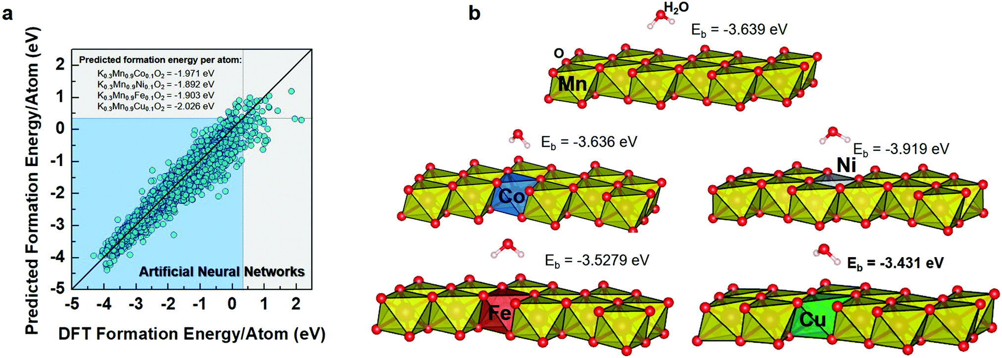 | ||
| Fig. 1 Test results of machine learning models with scientific population from a high-throughput computational thermodynamic approach; (a) predicted safety and formation energy per atom by the ML models compared with calculated formation energy per atom. (b) Schematic images of Eads; adsorption energy between water molecules and transition metal (Co, Ni, Fe, Cu) substances. | ||
We used DFT calculations to further confirm the structures and calculate the adsorption energies (Eads) of molecular water on the surface of the corresponding proposed compounds since the air stability is critical as cathode materials for KIB application (Fig. 1b). Although the ML model can predict crystal stability quantitatively, DFT calculations are required to accurately assess the optimized structures. The optimized structures of the proposed compounds are shown in Fig. S1 (ESI†). After the substitution of Co, Ni, Fe, or Cu, the structures maintain their layered characteristics. Compared to the pure KMO structure, these proposed structures exhibit lower unit cell volumes and decreased interlayer spacing, which is expected to be beneficial for structural stability, preventing charge ordering, and reducing electronic localization.31 However, for Zn–KMO, Al–KMO, and Bi–KMO optimization calculations, the convergences could not be achieved. This also highlights the importance of further implementation of DFT for materials screening.
For the next step, the proposed materials (Co–, Ni–, Fe–, and Cu–KMO) were considered for the adsorption energy calculations. The structure models were created using a (001) slab, and the atoms on the surface were allowed to relax. Fig. 1b depicts the optimized structures of adsorbed molecular water on the pure KMO, Co–, Ni–, Fe–, and Cu–KMO surfaces. The Eads of the substrates was calculated using the following formula:
| Eads = E(substrate/H2O) − E(substrate) − E(H2O) | (1) |
To evaluate the phase stability upon K insertion into the Cu–KMO, we carried out formation energy calculations and constructed the corresponding convex hull (Fig. 2a). The electrochemical K insertion reaction into the Cu–KMO structure can be written as:
| K + Mn0.9Cu0.1O2 ↔ K1Mn0.9Cu0.1O2 | (2) |
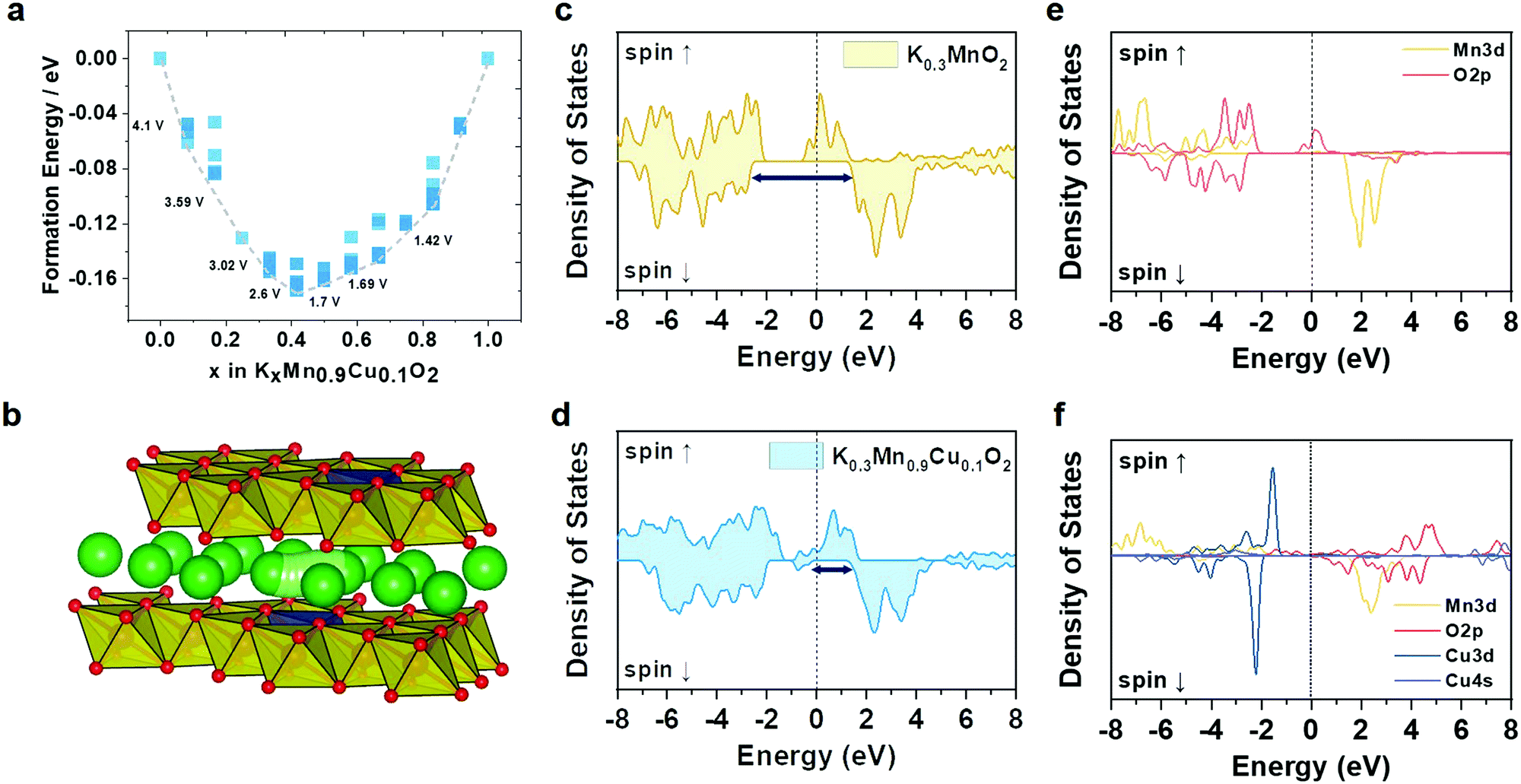 | ||
| Fig. 2 (a) Formation energies and convex hull of P′3-KMCO. (b) and (c) Calculated total DOS of KMO. (d) Crystal structure and K+ diffusion path of P′3-KMCO visualized using the VESTA program. (e) and (f) Calculated total DOS of KMCO. | ||
The formation energy can be thus calculated as a function of K concentration using the following equation:
| Ef = E[KxMn0.9Cu0.1O2] − (x)E[K1Mn0.9Cu0.1O2] − (1−x)E[Mn0.9Cu0.1O2] | (3) |
Additionally, we further predicted the insertion voltage for stable structures using the following equation:
| V(x) = −ΔG/xzF | (4) |
![[thin space (1/6-em)]](https://www.rsc.org/images/entities/char_2009.gif) 485 A s mol−1), and z indicate the Gibbs free energy change after K insertion within the Cu–KMO structure, the Faraday's constant, and the number of charges transferred in the reaction per mole reactant, respectively.35–37 While the entropy contribution is relatively small and can be ignored, the ΔG value can be obtained from the change in the DFT internal energy (ΔE) by subtracting the internal energy of the K-inserted structure from the pre-K-inserted structure and K metal. Based on this calculation, the intercalation of K in the dilute limit concentration occurs at 4.1 V followed by the various voltage steps until it reaches 1.42 V, which is in agreement with typical KMO-based electrodes.38–40
485 A s mol−1), and z indicate the Gibbs free energy change after K insertion within the Cu–KMO structure, the Faraday's constant, and the number of charges transferred in the reaction per mole reactant, respectively.35–37 While the entropy contribution is relatively small and can be ignored, the ΔG value can be obtained from the change in the DFT internal energy (ΔE) by subtracting the internal energy of the K-inserted structure from the pre-K-inserted structure and K metal. Based on this calculation, the intercalation of K in the dilute limit concentration occurs at 4.1 V followed by the various voltage steps until it reaches 1.42 V, which is in agreement with typical KMO-based electrodes.38–40
To gain more insight into the ionic and electronic conductivities of the proposed electrode, the density of states (DoS) and climbing-image nudged elastic band (CI-NEB) calculations, respectively, were performed. A single K ion was introduced into the Cu–KMO structure, and a total of nine images were set to interpolate the K diffusion path; the corresponding pathway is shown in Fig. 2b. The calculated migration energy barrier of K in the Cu–KMO structure was 265 meV. This value is comparable to that of KMO, i.e., 264 meV. A slight deviation can be attributed to the reduced interlayer distance in the Cu–KMO structure. For practical battery applications, the migration energy is still acceptable.41 Additionally, total DoS (TDoS) and projected DoS (PDoS) of the Cu–KMO and KMO structures are shown in Fig. 2c–f. It can be observed that in the TDoS plots, the conduction and valence bands are overlapped for both structures, indicating half-metal characteristics.42 However, the minority spin (spin down) of the KMO shows a wider separation than the Cu–KMO. It is expected that the Cu–KMO material exhibits higher electronic conductivity and improved electrochemical performance. PDoS also reveals that the conduction and valence bands are primarily constructed through transition metal–oxygen hybridization. The presence of Cu within the structure introduces an impurity that reduces the spin-down separation, considerably affecting the electronic conductivity.
Experimental validation: material characterization
The K0.3MnO2 (KMO) and K0.3Mn0.9Cu0.1O2 (KMCO) compounds are successfully synthesized through polyol-assisted pyro-synthesis.43 The chemical composition of the KMO and KMCO were confirmed using inductively coupled plasma (ICP)-optical emission spectrometer (OES) analysis (see Table S3, ESI†). To obtain structural information regarding both products, synchrotron powder X-ray diffraction (XRD) was used. The profile-matched XRD patterns of both KMO and KMCO using the Rieteveld refinement method revealed a typical P′3-type layered structure belonging to the C2/m space group. The results showed good agreement between the observed and simulated data for the synthesized materials (Fig. 3a and b). The lower weighted profile factor (Rwp) (KMO: 10.2%, KMCO: 9.24%) and value of S approaching around 1.8 confirm the good quality of refinement with KMO and KMCO materials. The unit cell parameters obtained from the structural refinement were a = 5.1263 Å, b = 2.8501 Å, and c = 7.1525 Å for KMO, and a = 5.0722 Å, b = 2.8676 Å, and c = 7.1556 Å for KMCO. The increase in the lattice parameters of the c-axis was evident because the Cu2+ ions have a larger ionic size than Mn3+ (Cu2+: 0.73 Å vs. Mn3+: 0.645 Å) and were successfully located in the TMO2 layers (TM = transition metal) without substitution of the K-ion sites. The insets in Fig. 3a and b show the P′3-type KMO and KMCO structures as illustrated by VESTA software. It was found that Cu substitution into the MO2 layer decreased the interplanar distance of the K layer (KMO: 5.138 Å vs. KMCO: 5.127 Å). This is because substituting a small number of Mn3+ with Cu2+ effectively decreases the electronic localization. This results in an expansion of the TMO2 layers and a contraction of the K layer spacing associated with a decrease in interaction between TM and O and enhancement of the binding energy between K and O.44 As shown in the scanning and transmission electron microscopy (SEM and TEM) images in Fig. 3c–f and Fig. S2 (ESI†), the KMO and KMCO revealed hexagonal nanoparticles with an average diameter of 500 nm. Both with and without Cu substitution, the products exhibited a smooth particle surface without impurities. The high-resolution TEM images of KMCO revealed a high crystalline layered structure and the measured interlayer spacing coincided with the d-spacing of the (001) plane. The selected area electron diffraction (SAED) pattern of KMCO showed well-defined diffraction spots, from which the direction of the incident electron beam is generated with the zone axis oriented along the [1 −1 2] direction. The SAED pattern of KMCO was a well indexed monoclinic crystal (C2/m space group), which was also consistent with the XRD results. The TEM energy dispersive spectroscopy (EDS) mapping results clearly showed various elements uniformly distributed in particles, and the measured atomic ratio of K, Mn, and Cu was 0.3:0.9:0.1, which is in good agreement with the ICP analysis data in Table S3 (ESI†). As with the KMCO materials, the KMO has similar morphology and particle size, and the diffraction pattern (lattice fringe and SAED pattern) is well matched to a monoclinic crystal consistent with the XRD results. Additionally, EDS mapping confirmed that the elemental distributions of K, Mn, and O, excluding Cu, were uniformly distributed (Fig. 3g).
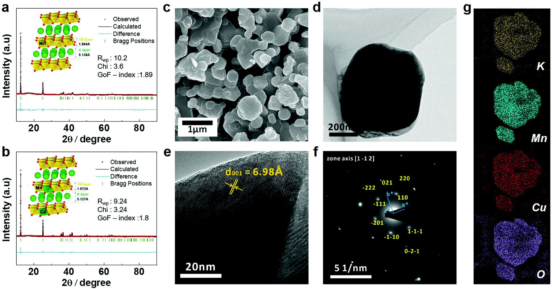 | ||
| Fig. 3 Rietveld-refinement profiles of XRD data of (a) KMO and (b) KMCO (inset: crystal structure by vesta). Microscopic analysis of KMCO particles: (c) SEM image, (d) TEM image, (e) HR-TEM image with lattice fringe and (f) SAED pattern. (g) EDS mapping of KMCO (yellow: K, cyan: Mn, red: Cu, purple: O). | ||
To obtain more insight into charge compensation, we performed X-ray photoelectron spectroscopy (XPS) and X-ray absorption near edge structure (XANES) analyses for the pure KMO and Cu-doped KMO (KMCO) samples. Fig. 4a and b shows the Mn 2p XPS spectra of the KMO and KMCO. Two peaks associated with the Mn 2p3/2 and Mn 2p1/2 spectra lie between 660 eV and 635 eV. In particular, the binding energies of ∼643 eV and ∼657 eV are related to Mn4+,45 and ∼642 eV and ∼653 eV are ascribed to Mn3+.46 Thus, these Mn 2p spectra indicate the presence of Mn4+ for both materials and demonstrate that a Cu ion successfully substitutes a Mn3+ ion as expected. Furthermore, the KMCO material possesses a more prominent Mn4+ state than that of the KMO counterpart, as evidenced by the shifting of Mn 2p1/2 toward a higher binding energy value and the increasing corresponding intensity. The presence of Cu in the doped sample was also evaluated. It can be observed that the Cu 2p1/2 and 2p3/2 spectra of the sample are located at ∼953 eV and ∼932 eV, indicating that Cu exists in the doped sample.47 XPS data further validated the valence states of Mn and Cu ions in the KMO and KMCO using synchrotron XANES. The K-edge spectra of the transition metals are compared to those of the reference: Mn(III) state (Mn2O3), Mn(IV) state (MnO2), and Cu(II) states (CuO), as presented in Fig. 4c and d. As expected, the XANES spectra of both the KMO and KMCO materials are situated between Mn2O3 and MnO2, indicating that the average oxidation states of Mn in the samples exist in mixed Mn3+ and Mn4+ states. More precisely, the Mn K-edge spectrum of KMCO is located closer to that of MnO2 (Mn4+), while the Cu K-edge spectrum of KMCO coincides with that of CuO (Cu2+).
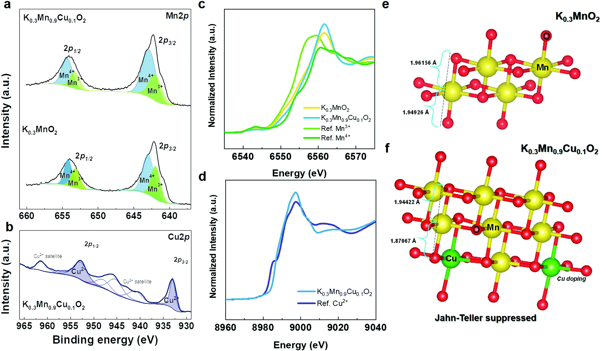 | ||
| Fig. 4 (a) Mn 2P XPS spectra of KMO and KMCO and (b) Cu 2P XPS spectra of KMCO. (c) Mn K-edge XANES spectra of KMO and KMCO (ref. Mn2O3 and MnO2). (d) Cu K-edge XANES spectra of KMCO (ref. CuO). DFT structure model of Jahn teller distortion in (e) KMO and (f) KMCO. | ||
The drawback of using Mn3+ in cathode materials is observable in the reduced electrochemical performance: it causes severe capacity fading and structural instability. Therefore, it is worth highlighting that the decreased concentration of Mn3+ plays a key role in the structural stability by suppressing the Jahn–Teller distortion. The increase in Mn4+ concentration leads to an increase in the average oxidation state of Mn and further prevents the occurrence of the Jahn–Teller distortion due to Mn3+.48 XPS and XANES data are in line with our DFT structure model, wherein for the Cu–KMO (K = 0.3) configuration model obtained from the Supercell program,32 the majority of Mn exists in the 4+ state (∼63%). As shown in Fig. 4e and f, the pure KMO sample exhibits longer average Mn–O bond length due to Jahn–Teller distortion compared to that of the Cu-doped KMO material.49 Furthermore, for electrochemical reaction, after being further potassiated at the K concentration of 0.41 and 0.5, the Mn–O bond lengths were also calculated to be 1.9134 and 1.9161 Å, respectively (KMO: 1.923 and 1.9238 Å), which are also shorter than that of the pure KMO sample. After deep discharging at 1.5 V, Mn–O bonding in KMO was 1.9387 Å with elongation in bond length (KMCO: 1.9126 Å) (Fig. S4, ESI†); and this further proves the benefit of Cu doping.
Experimental validation: battery performances
In order to investigate the fundamental electrochemical properties of KMO and KMCO cathodes, galvanostatic charge–discharge experiments were performed in a half-cell using a K metal anode and 0.5 M potassium hexafluorophosphate (KPF6) dissolved in ethylene carbonate (EC):diethylene carbonate (DEC) = 1:1 electrolyte. Prior to galvanostatic cycling test, linear sweep voltammetry (LSV) was evaluated to investigate the electrolyte stability. In the anodic scan up to 6 V (vs. K/K+), the LSV data demonstrate that no current developed up to 3.9 V; however, a noticeable current appeared between 4.1 and 4.2 V (vs. K/K+), indicating a start of electrolyte decomposition (Fig. S5, ESI†). Fig. 5 illustrates the comprehensive electrochemical performances of the KMO and KMCO cathodes in the voltage range of 1.5–3.9 V. Fig. S6 (ESI†) exhibits the cyclic voltammetry (CV) curves of the KMO and KMCO cathodes versus K/K+ at a scan rate of 0.2 mV s−1. The KMCO cathode exhibited a sharp peak and a pair of oxidation/reduction peaks at 2.58/1.92, 2.89/2.41, and 3.84/3.73 V, which are typically related to the redox couples of Mn3+/Mn4+.50,51 The possibility of Cu2+/Cu3+ redox activity around 3.3 V, as observed from CV analysis, was also evaluated by DFT calculations by considering the occupation numbers as the eigenvalues of the 5 × 5 occupation matrix for each spin.52 The occupation numbers of d-orbitals for both spins are presented in Table S6 (ESI†). It can be observed that at 3.3 V, there are 8 electrons present in the Cu 3d orbital; this resembles the electron configuration of Cu3+ ([Ar] 3d8). In other words, theoretical study also suggests the probability of Cu2+/Cu3+ redox activity for a KMCO sample. These peaks are attributed to the redox couple of Cu2+/Cu3+, except for the redox reaction peaks of Mn3+/Mn4+. Along with the theoretical studies, the changes in the oxidation state of Cu2+/Cu3+ were further investigated through ex situ X-ray photoelectron spectroscopy (XPS) analysis. The KMCO electrodes for the XPS analyses were sampled at different states of charge at 3.2 and 3.5 V (Fig. S7, ESI†). In the Cu 2p XPS spectra, the peak at 933.09 eV,48 corresponding to Cu2+ shifts toward high binding energy on increasing the charging potential from 3.2 to 3.5 V, indicating a Cu2+/Cu3+ redox activity situated around 3.4 V. The charge compensation mechanisms during de/potassiation were further identified in ex situ XANES at the end of the charge/discharge state (Fig. S9, ESI†). After charging to 3.9 V, the Mn K-edge of KMCO is located in the high energy region corresponding to Mn4+, and after discharging to 1.5 V, the Mn k-edge shifts toward the low energy region of Mn3+. According to the K movement, the Mn K-edge shift toward high and low energies depends on the Mn oxidation state. Reversible charge compensation occurs between Mn3+ and Mn4+ between 1.5 V and 3.9 V. Furthermore, the Cu K-edge spectra change reversibly from high energy to low energy at the end of discharge, related to the Cu2+/Cu3+ redox couple for charge compensation during charging–discharging, indicating that the Cu ion is electrochemically active (Fig. S9b, ESI†).
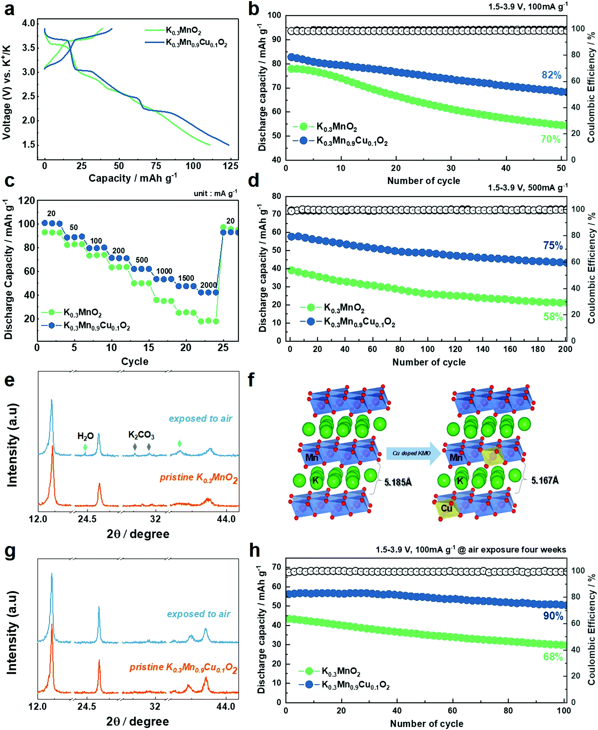 | ||
| Fig. 5 (a) 1st charge–discharge curves of KMO and KMCO at 10 mA g−1. (b) Cycling performance of KMO and KMCO at 100 mA g−1 and (d) 500 mA g−1, respectively. (c) Rate performance of the KMO and KMCO cathode at various current densities (20 to 2000 mA g−1). (d) Cycling performance of KMO and KMCO at 500 mA g−1. (e) Comparison of XRD patterns of KMO between pristine and after four weeks air-exposure. (f) Comparison of calculated K layer distance of air exposed KMO and KMCO after four weeks. (g) Comparison of XRD patterns of KMCO between pristine and after four weeks air-exposure. (h) Cycling stability of KMO and KMCO at 100 mA g−1 after four weeks air-exposure. | ||
Fig. 5a shows the first charge–discharge voltage profiles of the KMO and KMCO cathode. Reversible capacities of 111 and 124 mA h g−1 were measured at a current density of 10 mA g−1 in the KMO and KMCO cathodes, respectively. The capacity improvement achieved through the Cu substitution is therefore ≈15%, and the KMCO cathode exhibited improved cycling stability compared to the KMO cathode at a current density of 100 mA g−1 (KMO: 70% vs. KMCO: 82%, after 50 cycles). The enhanced capacity retention is more pronounced at high current densities. The long lifetime of the KMCO cathode is also confirmed at a high current density of 500 mA g−1 (Fig. 5d). After 200 cycles, the KMCO cathode exhibits a remarkable capacity retention with higher discharge capacity than that of the Cu-free cathode. (KMO: 58% vs. KMCO: 75%). Although the electrolyte solution is unstable at a high voltage region over 3.9 V (as seen in Fig. S5, ESI†), the KMCO cathode also demonstrates remarkable improvement in its cycling stability in the wide voltage range of 1.5–4.2 V (Fig. S10, ESI†). The comparative rate capabilities were performed at various current densities from 20 to 2000 mA g−1 (Fig. 5c). For all current densities, the KMCO cathode delivered higher discharge capacities than the KMO cathode. In particular, high discharge capacities of 64 mA h g−1 and 43 mA h g−1 can be retained for the KMCO cathode even at extremely high current densities of 500 mA g−1 and 2500 mA g−1, respectively. The KMCO cathode showed improved rate performance than the KMO cathode, indicating that the Cu substitution in KMO benefits the K-ion intercalation/deintercalation kinetics. Along with improved electronic conductivity (see the DFT in Fig. 2c–f), electrochemical impedance spectroscopy (EIS) was further carried out to investigate the significant enhancement of KMCO in K-ion diffusion kinetics. Nyquist plots were measured after 50 cycles at 100 mA g−1, and the results are shown in Fig. S11 and Table S7 (ESI†). Fitting the Nyquist plot deconvoluted the impedance spectrum into the resistances of the electrolyte solution (Rs), interfacial nanolayer (Rsei), and charge transfer (Rct). The semicircle in the KMCO cathode impedance spectra is more than 2.5 times smaller than that of the KMO cathode. Additionally, K+ ion diffusion coefficients (DK+) were calculated from the slope line at low frequency as Warburg impedance in the Nyquist plot. The DK+ values of KMO and KMCO are ∼3.84451 × 10⁻¹⁴ cm2 s−1 and ∼1.15416 × 10⁻¹³ cm2 s−1, respectively, indicating faster K-ion diffusion in KMCO. Furthermore, the bulk resistance of the powder materials was established by a four-probe measurement to calculate electrical conductivity. The KMCO has higher electrical conductivity (5.49 × 10⁻⁴ S cm−1) than KMO (3.08 × 10⁻⁴ S cm−1), which corresponds with the DFT calculations.
To evaluate the kinetics of KMCO in the de/potassiation process, the CV curves are analyzed at various scan rates from 0.2 to 1.0 mV s−1 (Fig. S12, ESI†). For a fixed sweep rate, the specific contribution of the pseudo-capacitance and diffusion behavior can be explained by the following formula:
| i = k1v + k2v1/2 | (5) |
| i = avb | (6) |
i = loga + blogv), the b-value is calculated as 0.5, indicating that capacities of KMCO originate from diffusion-dominated processes in K-ion batteries (cathodic: 0.63, anodic: 0.56).
It is most likely that difficulty in synthesis and a lack of diversity in the K-based cathode material is primarily attributable to moisture sensitivity. In particular, most of the potassiated layered oxide cathode materials are hygroscopic and can react with water in the air to form a hydrated phase. Consequently, this sensitivity to moisture hinders the insertion/extraction of K+ ions in and out of the layered structure, leading to low reversible capacity and poor rate capability. Hence, the ease of handling under a moist environment has been considered a critical issue in the development of K-layered oxide cathode materials for practical KIBs. Along with the DFT calculations in Fig. 1b, decreases in the interplanar distance of the K layer caused by the incorporation of Cu into the Mn site (inset in Fig. 3a and b) inhibit the insertion of water molecules and reduce the water sensitivity of pristine KMO. To confirm the air stability, an aging experiment was conducted, wherein the materials were exposed to air with a relative humidity of ≈55%. A comparative study of the XRD evolution of the KMO and KMCO cathodes was conducted after four weeks (Fig. 5e–g and Fig. S13, ESI†). In the case of the KMO cathode, the (001) peak split into two and shifted toward a lower angle (likely a K-deficient phase), indicating an enlarged inter-slab distance according to Bragg's equation (2d sinθ = nλ). The increase in inter-slab distance of the exposed KMO cathode is attributable to increased repulsion between adjacent O layers due to the decreased shielding effect of K+ ions (Fig. 5f). In addition, distinctive peaks at 24.3° and 40.5° in the hydrate phase (JCPDS: 01-085-0856) and the peaks at 30.1° and 31.4° for the K2CO3 (JCPDS: 01-070-0292) phase are observed. Once the cathode is exposed to air or moisture, water oxidizes the transition metal ions with the concomitant removal of K+ ions, which further react with CO2 and H2O in air to form K2CO3. In contrast, throughout the four weeks, the original peaks in the P′3 phase were well retained for the KMCO cathode without an impurity phase. This may be due to the incorporation of Cu into the Mn site. Layered oxides can improve the surface structure as well, thus protecting the material from direct contact with air and avoiding removal of K+ ions when exposed to air. Moreover, the KMO particles were found to radically aggregate and be covered by impurities (likely, K2CO3) compared to those of KMCO when exposed to air for four weeks (Fig. S14, ESI†). Complementing the excellent air stability, the electrochemical properties are also improved upon Cu substitution after air exposure (Fig. 5h and Fig. S15, ESI†). Notably, the exposed KMCO cathode exhibits a high reversible capacity of 57 mA h g−1 at a current rate of 100 mA g−1 (exposed KMO: 43 mA h g−1) and a long-term cycling stability over 100 cycles at a current rate of 500 mA g−1. Nonetheless, although Cu-doping improved the air stability of K0.3MnO2, there is still capacity loss after air exposure. For upcoming studies, a co-substitution strategy through multiple elemental doping54,55 and/or surface coatings56,57 can promise further improvement of environmental stability for KMO. In order to correlate between the electrochemical performance and morphological and structural durability of KMO and KMCO, finally, ex situ TEM analysis was carried out for the cycled KMO and KMCO cathodes. Bright field TEM and HR-TEM images of the cycled KMO particle (Fig. S16, ESI†) showed that the layered structure has collapsed and the structure has become amorphous at the particle edge. In contrast, bright field TEM and HR-TEM images revealed that the cycled KMCO particles retained their original morphology and reflect a smooth particle surface, thus verifying that there was hardly any distortion in the layered structure of this active mass even at the particle edges, which are the most sensitive locations.
Conclusions
New battery technologies are sorely needed in energy-related fields and beyond. Recently, K-ion batteries (KIBs) have shown great potential to become a competing technology to the LIBs for large-scale energy storage systems in the future.58–62 In this work, for the first time, we proposed a new material discovery platform assisted by a combination of ML model-prediction, DFT calculations, and experimental validation for KIBs. First, the ML model was built based on 27578 entries and then used to predict crystal stabilities of seven different proposed metal-doped KxMnO2 samples before feeding into the DFT calculations for enhancing the physicochemical properties and environmental stability of the KxMnO2 cathode. DFT validation suggests that P′3-type K0.3Mn0.9Cu0.1O2 (KMCO) is expected to be beneficial for structural stability, air-stability, preventing charge ordering, and reducing electronic localization. Experimentally, it is proved that the success of Cu2+ substitution into Mn sites reinforces the structural stability by suppression of Jahn–Teller distortion and water sensitivity and finally improved electrochemical K storage properties of the KMO cathode. Even after four weeks air-exposure period, as a result, the KMCO cathode exhibits a high reversible capacity of 57 mA h g−1 at a current rate of 100 mA g−1 and a long-term cycling stability over 100 cycles at a current rate of 500 mA g−1. This powerful platform provides an effective means of new material design without revisiting the previous work and thus reducing time consuming processes and costs in a broad range of social, scientific and industrial societies. We strongly believed that the proposed platform provides wide applicability in various research sectors for discovering the new materials as well as battery applications.Conflicts of interest
The authors declare no competing financial interest.Acknowledgements
This work was supported by the National Research Foundation of Korea (NRF) grant funded by the Korea government (MSIT) (NRF-2021R1A4A1052051 and NRF-2018R1A5A1025224).References
- B. Scrosati, M. Bottini and T. Mustelin, Nat. Nanotechnol., 2007, 2, 598–599 CrossRef CAS PubMed.
- N. Yabuuchi, K. Kubota, M. Dahbi and S. Komaba, Chem. Rev., 2014, 114, 11636–11682 CrossRef CAS PubMed.
- A. Eftekhari, Z. Jian and X. Ji, ACS Appl. Mater. Interfaces, 2017, 9, 4404–4419 CrossRef CAS PubMed.
- N. Xiao, W. D. McCulloch and Y. Wu, J. Am. Chem. Soc., 2017, 139, 9475–9478 CrossRef CAS PubMed.
- M. A. Halcrow, Chem. Soc. Rev., 2013, 42, 1784–1795 RSC.
- J. C. Pramudita, D. Sehrawat, D. Goonetilleke and N. Sharma, Adv. Energy Mater., 2017, 7, 1602911 CrossRef.
- J. M. Ge, L. Fan, J. Wang, Q. Zhang, Z. Liu, E. Zhang, Q. Liu, X. Yu and B. Lu, Adv. Energy Mater., 2018, 8, 1801477 CrossRef.
- Y. You, A. Dolocan, W. Li and A. Manthiram, Nano Lett., 2019, 19, 182–188 CrossRef CAS PubMed.
- H. Kim, D. H. Seo, J. C. Kim, S. H. Bo, L. Liu, T. Shi and G. Ceder, Adv. Mater., 2017, 29, 1702480 CrossRef PubMed.
- Q. Zhang, C. Didier, W. K. Pang, Y. Liu, Z. Wang, S. Li, V. K. Peterson, J. Mao and Z. Guo, Adv. Energy Mater., 2019, 9, 1900568 CrossRef.
- G. Hautier, C. C. Fischer, A. Jain, T. Mueller and G. Ceder, Chem. Mater., 2010, 22, 3762–3767 CrossRef CAS.
- J. Schmidt, J. Shi, P. Borlido, L. Chen, S. Botti and M. A. L. Marques, Chem. Mater., 2017, 29, 5090–5103 CrossRef CAS.
- B. Meredig, A. Agrawal, S. Kirklin, J. E. Saal, J. W. Doak, A. Thompson, K. Zhang, A. Choudhary and C. Wolverton, Phys. Rev. B, 2014, 89, 094104 CrossRef.
- S. Lu, Q. Zhou, Y. Ouyang, Y. Guo, Q. Li and J. Wang, Nat. Commun., 2018, 9, 3405 CrossRef PubMed.
- G. H. Gu, J. Noh, I. Kim and Y. Jung, J. Mater. Chem. A, 2019, 7, 17096–17117 RSC.
- S. K. Kauwe, J. Graser, R. Murdock and T. D. Sparks, Comput. Mater. Sci., 2020, 174, 109498 CrossRef.
- Y. Zhuo, A. Mansouri Tehrani and J. Brgoch, J. Phys. Chem. Lett., 2018, 9, 1668–1673 CrossRef CAS PubMed.
- A. Mansouri Tehrani, A. O. Oliynyk, M. Parry, Z. Rizvi, S. Couper, F. Lin, L. Miyagi, T. D. Sparks and J. Brgoch, J. Am. Chem. Soc., 2018, 140, 9844–9853 CrossRef CAS PubMed.
- M. W. Gaultois, A. O. Oliynyk, A. Mar, T. D. Sparks, G. J. Mulholland and B. Meredig, APL Mater., 2016, 4, 053213 CrossRef.
- S. K. Kauwe, T. M. Welker and T. D. Sparks, Integr. Mater. Manuf. Innov., 2020, 9, 213–220 CrossRef.
- A. Jain, S. P. Ong, G. Hautier, W. Chen, W. D. Richards, S. Dacek, S. Cholia, D. Gunter, D. Skinner, G. Ceder and K. A. Persson, APL Mater., 2013, 1, 011002 CrossRef.
- L. Ward, A. Dunn, A. Faghaninia, N. E. R. Zimmermann, S. Bajaj, Q. Wang, J. Montoya, J. Chen, K. Bystrom, M. Dylla, K. Chard, M. Asta, K. A. Persson, G. J. Snyder, I. Foster and A. Jain, Comput. Mater. Sci., 2018, 152, 60–69 CrossRef.
- D. K. Barupal and O. Fiehn, Environ. Health Perspect., 2019, 127, 2825–2830 CrossRef PubMed.
- X. Zhang, Z. Wei, K. N. Dinh, N. Chen, G. Chen, F. Du and Q. Yan, Small, 2020, 16, 2002700 CrossRef CAS PubMed.
- H. Pan, A. M. Ganose, M. Horton, M. Aykol, K. A. Persson, N. E. R. Zimmermann and A. Jain, Inorg. Chem., 2021, 60, 1590–1603 CrossRef CAS PubMed.
- G. Hautier, C. Fischer, V. Ehrlacher, A. Jain and G. Ceder, Inorg. Chem., 2011, 50, 656–663 CrossRef CAS PubMed.
- T. Xiong, M. Zhu, Y. Zhang, W. S. V. Lee, Z. G. Yu and J. Xue, Batteries Supercaps, 2020, 3, 519–526 CrossRef CAS.
- C. M. Julien and A. Mauger, Nanomaterials, 2020, 31, 012001 Search PubMed.
- Z. Ye, T. Li, G. Ma, Y. Dong and X. Zhou, Adv. Funct. Mater., 2017, 27, 1704083 CrossRef.
- Z. Chen, W. Zhang and Z. Yang, Nanotechnology, 2019, 12, 111003 Search PubMed.
- H. R. Yao, P. F. Wang, Y. Gong, J. Zhang, X. Yu, L. Gu, C. Ouyang, Y. X. Yin, E. Hu, X. Q. Yang, E. Stavitski, Y. G. Guo and L. J. Wan, J. Am. Chem. Soc., 2017, 139, 8440–8443 CrossRef CAS PubMed.
- K. Okhotnikov, T. Charpentier and S. Cadars, J. Cheminf., 2016, 8, 17 Search PubMed.
- J. Alvarado, M. A. Schroeder, T. P. Pollard, X. Wang, J. Z. Lee, M. Zhang, T. Wynn, M. Ding, O. Borodin, Y. S. Meng and K. Xu, Energy Environ. Sci., 2019, 12, 780–794 RSC.
- N. Naveen, W. B. Park, S. P. Singh, S. C. Han, D. Ahn, K. S. Sohn and M. Pyo, Small, 2018, 14, 1803495 CrossRef PubMed.
- A. Urban, D. H. Seo and G. Ceder, npj Comput. Mater., 2016, 2, 16002 CrossRef CAS.
- M. H. Alfaruqi, S. Islam, J. Lee, J. Jo, V. Mathew and J. Kim, J. Mater. Chem. A, 2019, 7, 26966–26974 RSC.
- M. H. Alfaruqi, S. Kim, S. Park, S. Lee, J. Lee, J. Y. Hwang, Y. K. Sun and J. Kim, ACS Appl. Mater. Interfaces, 2020, 12, 16376–16386 CrossRef CAS PubMed.
- C. L. Liu, S. H. Luo, H. B. Huang, Y. C. Zhai and Z. W. Wang, Chem. Eng. J., 2019, 356, 53–59 CrossRef CAS.
- J. U. Choi, J. Kim, J. H. Jo, H. J. Kim, Y. H. Jung, D. C. Ahn, Y. K. Sun and S. T. Myung, Energy Storage Mater., 2020, 25, 714–723 CrossRef.
- X. Liu, J. Q. Huang, Q. Zhang and L. Mai, Adv. Mater., 2017, 29, 1601759 CrossRef PubMed.
- Z. Rong, R. Malik, P. Canepa, G. Sai Gautam, M. Liu, A. Jain, K. Persson and G. Ceder, Chem. Mater., 2015, 27, 6016–6021 CrossRef CAS.
- Y. N. Xu, W. Y. Ching and Y. M. Chiang, J. Appl. Phys., 2004, 95, 6583–6585 CrossRef CAS.
- J. Gim, V. Mathew, J. Lim, J. Song, S. Baek, J. Kang, D. Ahn, S.-J. Song, H. Yoon and J. Kim, Sci. Rep., 2012, 2, 946 CrossRef PubMed.
- Y. Wang, J. Liu, B. Lee, R. Qiao, Z. Yang, S. Xu, X. Yu, L. Gu, Y. S. Hu, W. Yang, K. Kang, H. Li, X. Q. Yang, L. Chen and X. Huang, Nat. Commun., 2015, 6, 6401 CrossRef CAS PubMed.
- Y. Yokoyama, D. Ootsuki, T. Sugimoto, H. Wadati, J. Okabayashi, X. Yang, F. Du, G. Chen and T. Mizokawa, Appl. Phys. Lett., 2015, 107, 2–6 CrossRef.
- A. C. Ferrel-Álvarez, M. A. Domínguez-Crespo, H. Cong, A. M. Torres-Huerta, S. B. Brachetti-Sibaja and W. De La Cruz, J. Alloys Compd., 2018, 735, 1750–1758 CrossRef.
- P. Pallavicini, G. Dacarro, P. Grisoli, C. Mangano, M. Patrini, F. Rigoni, L. Sangaletti and A. Taglietti, Dalton Trans., 2013, 42, 4552–4560 RSC.
- T. R. Chen, T. Sheng, Z. G. Wu, J. T. Li, E. H. Wang, C. J. Wu, H. T. Li, X. D. Guo, B. H. Zhong, L. Huang and S. G. Sun, ACS Appl. Mater. Interfaces, 2018, 10, 10147–10156 CrossRef CAS PubMed.
- Q. Liu, Z. Hu, M. Chen, C. Zou, H. Jin, S. Wang, S. L. Chou and S. X. Dou, Small, 2019, 15, 1805381 CrossRef PubMed.
- T. Deng, X. Fan, J. Chen, L. Chen, C. Luo, X. Zhou, J. Yang, S. Zheng and C. Wang, Adv. Funct. Mater., 2018, 28, 1800219 CrossRef.
- X. Liu, W. Zuo, B. Zheng, Y. Xiang, K. Zhou, Z. Xiao, P. Shan, J. Shi, Q. Li, G. Zhong, R. Fu and Y. Yang, Angew. Chem., Int. Ed., 2019, 58, 18086–18095 CrossRef CAS PubMed.
- P. H. L. Sit, R. Car, M. H. Cohen and A. Selloni, Inorg. Chem., 2011, 50, 10259–10267 CrossRef CAS PubMed.
- H. Lindström, S. Södergren, A. Solbrand, H. Rensmo, J. Hjelm, A. Hagfeldt and S. E. Lindquist, J. Phys. Chem. B, 1997, 101, 7710–7716 CrossRef.
- D. Wang, C. Shi, Y. P. Deng, Z. Wu, Z. Yang, Y. Zhong, Y. Jiang, B. Zhong, L. Huang, X. Guo and Z. Chen, Nano Energy, 2020, 70, 104539 CrossRef CAS.
- Q. Yang, P. F. Wang, J. Z. Guo, Z. M. Chen, W. L. Pang, K. C. Huang, Y. G. Guo, X. L. Wu and J. P. Zhang, ACS Appl. Mater. Interfaces, 2018, 10, 34272–34282 CrossRef CAS PubMed.
- F. Wu, X. Zhang, T. Zhao, L. Li, M. Xie and R. Chen, ACS Appl. Mater. Interfaces, 2015, 7, 3773–3781 CrossRef CAS PubMed.
- W. Kong, H. Wang, L. Sun, C. Su and X. Liu, Appl. Surf. Sci., 2019, 497, 143814 CrossRef CAS.
- Y. Zhong, X. Xu, J. P. Veder and Z. Shao, iScience, 2020, 23, 100943 CrossRef CAS PubMed.
- S. Guo, Q. Li, P. Liu, M. Chen and H. Zhou, Nat. Commun., 2017, 8, 135 CrossRef PubMed.
- Y. Zhong, J. Dai, X. Xu, C. Su and Z. Shao, ChemElectroChem, 2020, 7, 4949–4955 CrossRef CAS.
- J. Y. Hwang, S. T. Myung and Y. K. Sun, Chem. Soc. Rev., 2017, 46, 3529–3614 RSC.
- J. Y. Hwang, H. M. Kim, S. K. Lee, J. H. Lee, A. Abouimrane, M. A. Khaleel, I. Belharouak, A. Manthiram and Y. K. Sun, Adv. Energy Mater., 2016, 6, 1501480 CrossRef.
Footnotes |
| † Electronic supplementary information (ESI) available. See DOI: 10.1039/d1ee01136g |
| ‡ These authors contributed equally to this work. |
| This journal is © The Royal Society of Chemistry 2021 |