
Defect chemistry of disordered solid-state electrolyte Li10GeP2S12†
Prashun
Gorai
 *ab,
Hai
Long
b,
Eric
Jones
a,
Shriram
Santhanagopalan
b and
Vladan
Stevanović
*ab
*ab,
Hai
Long
b,
Eric
Jones
a,
Shriram
Santhanagopalan
b and
Vladan
Stevanović
*ab
aColorado School of Mines, Golden, CO 80401, USA. E-mail: pgorai@mines.edu; vstevano@mines.edu
bNational Renewable Energy Laboratory, Golden, CO 80401, USA
First published on 30th January 2020
Abstract
Several classes of materials, including thiophosphates, garnets, argyrodites, and anti-perovskites, have been considered as electrolytes for all-solid-state batteries. Native point defects and dopants play a critical role in impeding or facilitating fast ion conduction in these solid electrolytes. Despite its significance, comprehensive studies of the native defect chemistry of well-known solid electrolytes is currently lacking, in part due their compositional and structural complexity. Most of these solid-state electrolytes exhibit significant structural disorder, which requires careful consideration when modeling the point defect energetics. In this work, we model the native defect chemistry of a disordered solid electrolyte, Li10GeP2S12 (LGPS), by uniquely combining ensemble statistics, accurate electronic structure, and modern first-principles defect calculations. We find that VLi, Lii, and PGe are the dominant defects. From these calculations, we determine the statistics of defect energetics; formation energies of the dominant defects vary over ∼140 meV. Combined with previously reported ab initio molecular dynamics simulations, we find that anti-sites PGe promote Li ion conductivity, suggesting LGPS growth under P-rich/Ge-poor conditions will enhance ion conductivity. To this end, we offer practical experimental guides to enhance ion conductivity.
1 Introduction
All-solid-state batteries offer greater safety and higher energy and power densities compared to the currently employed Li- and Na-ion batteries that utilize flammable liquid electrolytes.1,2 Several classes of materials have been considered for solid-state electrolytes, including thiophosphates (e.g. Li10GeP2S12),3,4 garnets (e.g. Li7La3Zr2O12),5,6 argyrodites (e.g. Li6PS5Cl),7,8 LISICONs,9 NASICONs,10 anti-perovskites (e.g. Li3OCl)11,12etc. Most of these solid-state electrolytes exhibit significant structural disorder, which enables fast ion conduction.13,14 For instance, Li10GeP2S12 (LGPS) and derived compounds display complex site disorder, as shown in Fig. 1. In LGPS, the available Li sites are partially occupied and P/Ge exhibit substitutional disorder while the anion (S) sub-lattice is ordered.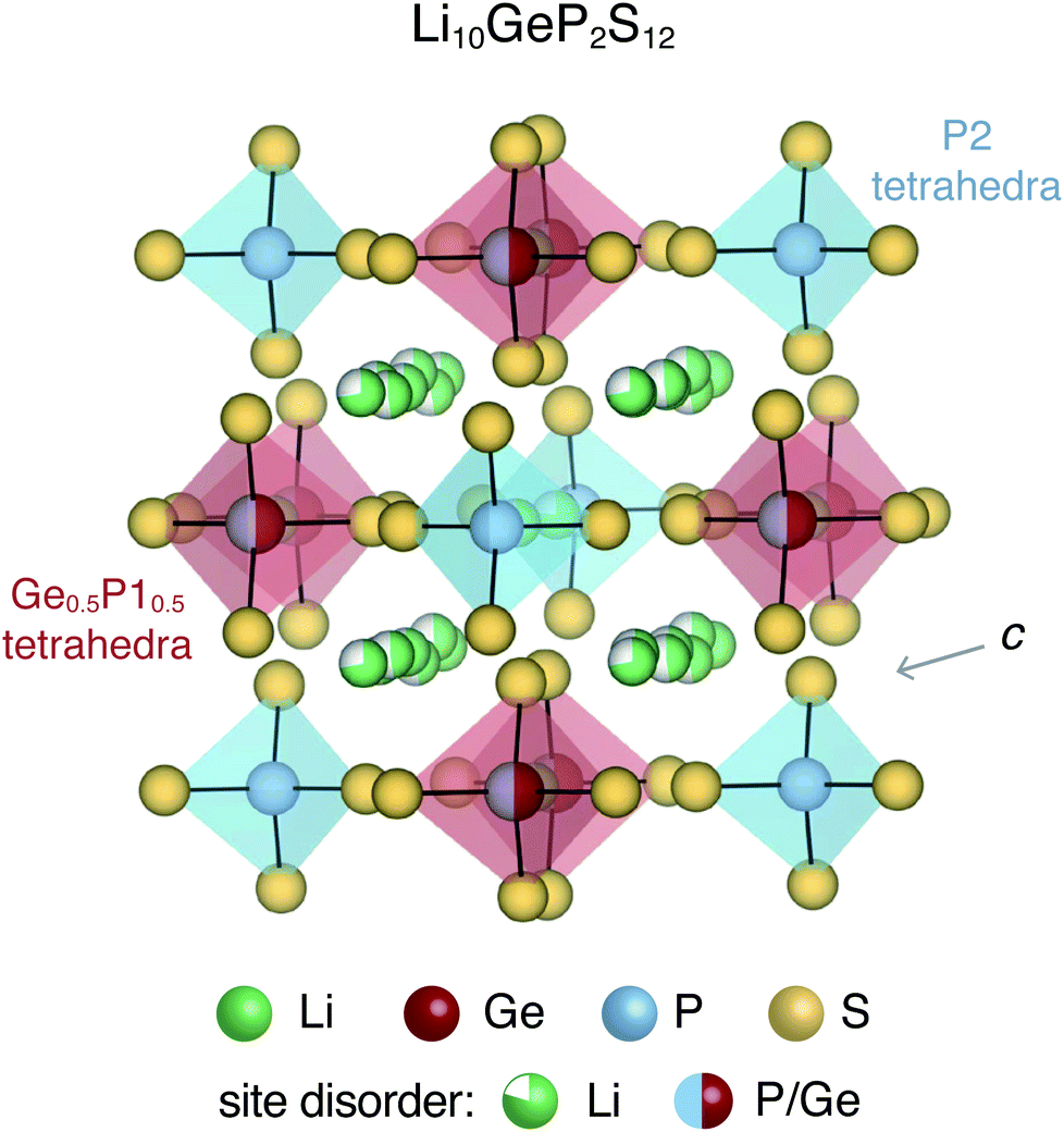 | ||
| Fig. 1 Tetragonal crystal structure of Li10GeP2S12 contains P2S4 tetrahedra and (Ge0.5P10.5)S4 tetrahedra with partially occupied Li sites in the c-axis channels and in the a–b plane bridging sites. The S sub-lattice and P2 sites are fully occupied. | ||
Intrinsic and extrinsic point defects play a critical role in determining the properties of materials, particularly semiconductors and insulators. First-principles defect calculations have proven immensely useful in the development of materials for thermoelectrics,15,16 photovoltaics,17,18 power electronics19,20etc. In solid-state battery electrolytes, native point defects and dopants could impede ion conduction by acting as diffusion path blockers, or enhance conduction by flattening the energy landscape for diffusion.21,22 Similarly, defects could influence ionic and electronic conduction in cathode materials.23,24 While direct observation and measurement of point defects is quite challenging, first-principles defect calculations can provide insights about the dominant defects, and their concentrations as well as electronic carrier concentrations. When combined with ab initio molecular dynamics simulations, the effect of point defects on the ion conductivity can also be quantitatively probed. The native defect energetics of ordered compounds for cathodes such as olivines (LiFePO4),23 cobaltites (e.g. LiCoO2),25 silicates (e.g. Li2MnSiO4)24 have been previously reported.
Despite its significance, comprehensive studies of the native defect chemistry of well-known solid electrolytes is currently lacking, in part due their compositional and structural complexity. In particular, the complex site disorder needs careful consideration when modeling the point defect chemistry.26,27 Recent attempts at modeling the point defect energetics in disordered solid-state electrolytes have utilized either a single ordered representation of the disordered structure28 or a low-temperature ordered phase.29 In this study, we model the native defect chemistry of a disordered solid electrolyte, Li10GeP2S12, by adopting a unique methodology that combines ensemble statistics and first-principles defect calculations to account for the disorder.
Li10GeP2S12 and derived compounds are among the solid-state electrolytes exhibiting the highest ionic conductivities.3,30 It is believed that the soft anion lattice and the structural disorder of LGPS enables high Li ion conductivity.31 The room-temperature tetragonal (P42/nmc) crystal structure of LGPS is characterized by (Ge0.5P10.5)S4 and P2S4 tetrahedra, interspersed with partially occupied Li sites, as shown in Fig. 1. The one-dimensional network of Li ions that form along the c-axis channels are primarily responsible for Li ion diffusion in LGPS, although the importance of Li ion diffusion in the a–b plane has also been recognized.32 Ever since its introduction in 2011, LGPS and related compounds have been extensively studied both experimentally31 as well as theoretically.32–34 The theoretical studies employing first-principles calculations have focused primarily on the phase stability,32,33 and ion diffusion mechanism.32–34 In contrast, the native defect chemistry of LGPS is largely unexplored, partly due to the associated computational challenges. Recently, Oh et al. used first-principles defect calculations to map the defect chemistry of LGPS.28 However, in this study, the disordered phase of LGPS was represented by a single ordered structure. In a disordered material, a multitude of different local bonding environments are possible, which could lead to variations in the formation energies of the same defect. Therefore, it is fundamentally important to account for the disorder and to determine the statistical variation in the defect formation energies.
In this study, we model the native defect chemistry of disordered LGPS by uniquely combining ensemble statistics, accurate electronic structure, and modern first-principles defect calculations. We use a Madelung energy minimization criteria in conjunction with ensemble statistics to select representative structures that account for structural disorder. For four representative structures, we perform state-of-the-art defect calculations and find that VLi, Lii, and PGe are the dominant defects. We also find that the formation energies of the dominant defects can vary over ∼140 meV across the representative structures. Combined with previously reported ab initio molecular dynamics simulations,28 we find that PGe defects promote Li ion conductivity, suggesting LGPS grown under P-rich/Ge-poor conditions would enhance ion conductivity.
2 Computational methods
2.1 Selecting structures for defect calculations
The tetragonal (P42/nmc) crystal structure of LGPS (Fig. 1) contains 4 unique Wyckoff sites of Li–Li1 (16h), Li2 (4d), Li3 (8f), Li4 (4c), one of Ge–Ge1 (4d), two of P–P1 (4d), P2 (2b), and three of S–S1 (8g), S2 (8g), S3 (8g), where the Wyckoff site symbols are shown in parentheses.35 The Li1 and Li3 sites form the one-dimensional network in the c-axis channels and Li2 and Li4 are the bridging sites lying in the a–b plane. While the anion sub-lattice (S1, S2, S3) and P2 site are fully occupied, the cation sub-lattices exhibit disorder, namely: (a) P1 and Ge1 sites have fractional occupation of 0.5, and (b) the 32 Li sites distributed over Li1–Li4 are occupied by 20 Li ions.Given the complexity of the disorder in LGPS, the number of possible atomic configurations in the LGPS structure is extremely large. As a first step, we utilize a computationally effective electrostatic (Madelung) energy minimization criterion28,32 to select 1000 configurations with lowest energies among all possible configurations in the 50-atom supercell. For this, we assume ideal ionic charges on Li (+1), Ge (+4), P (+5), and S (−2). Subsequently, these 1000 structures are fully relaxed with density functional theory (DFT) using the standard GGA-PBE functional.36 More details of the computational setup are provided in the next section (Section 2.2). The energy distribution of these 1000 structures (after DFT relaxation), also called thermodynamic density of states, is shown in Fig. 2(a).
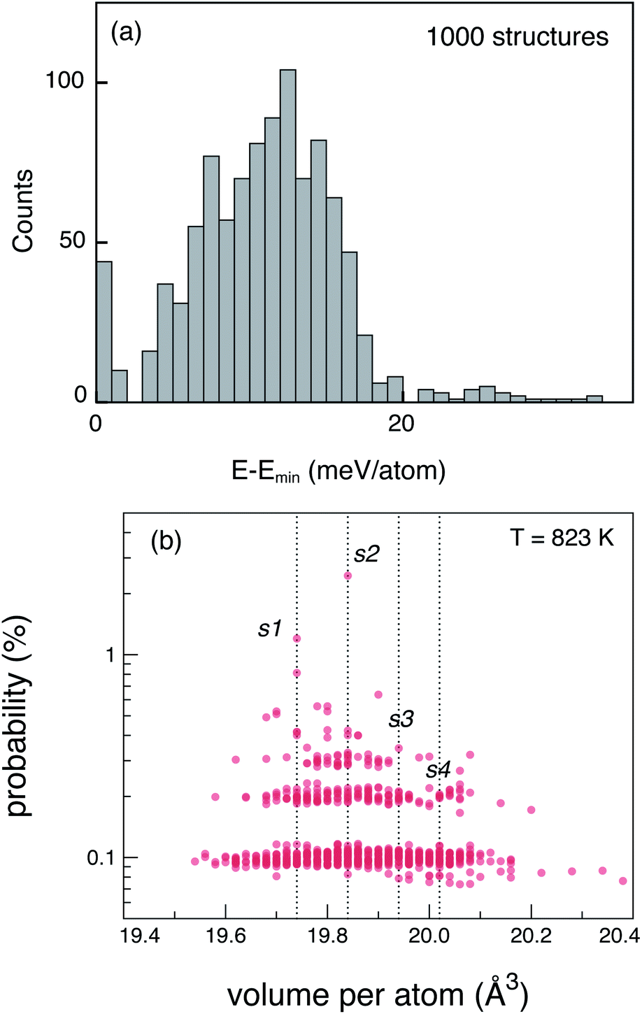 | ||
| Fig. 2 (a) Energy distribution of the 1000 DFT-relaxed, LGPS structures selected using the electrostatic minimization criterion. Energy is expressed per atom, relative to the lowest energy structure. (b) Probability distribution of the 1000 relaxed structures calculated using ensemble statistics at T = 823 K. Labels s1, s2, s3, and s4 are the four representative structures chosen for defect calculations. | ||
Next, we adopt an ensemble statistical procedure to select a collection of ordered structures (among the 1000 relaxed structures) to represent the disordered phase of LGPS. It has been recently shown that a disordered macrostate can be expressed as a thermodynamic average of structurally ordered microstates.37 This approach is predicated upon the statistical treatment of an ensemble (distribution) of local minima and has been shown to reproduce well the structural features of amorphous and glassy states.37 Another study has demonstrated that an ensemble-based model can be used to model the complex NMR spectra of disordered compounds.38 In this work, we apply ensemble statistics to the set of 1000 ordered structures obtained in the previous step from the Madelung energies criterion. The thermodynamic contribution of each microstate to the disordered phase of LGPS is proportional to g(E)exp[−(E − Emin)/kBT], where E is the energy of a microstate, g(E) is its degeneracy, and kB is the Boltzmann constant. Since the symmetry of all “ordered” configurations turns out to be P1 after DFT relaxations, the degeneracy of states (i.e. the multiplicity) is decided on the basis of equality of DFT total energies and DFT-relaxed volumes. The thermodynamic contribution of each microstate can be expressed as a probability 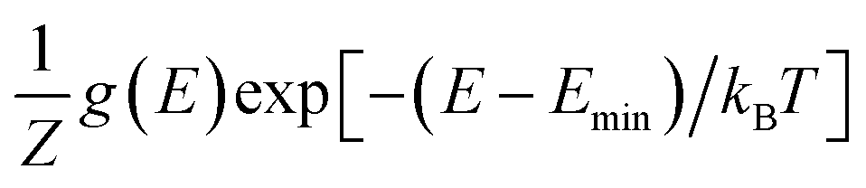 with Z being the normalization factor (partition function); Fig. 2(b) shows the probability distribution of the 1000 structures as a function of volume per atom assuming the typical synthesis temperature 823 K.3 An appropriate condition for selecting representative structures is to choose those with high probability according to ensemble statistics. For performing defect calculations, we chose two highly probable structures with slightly different cell volumes (19.74, 19.84 Å3 per atom), which are, henceforth, referred to as structure 1 (s1 in Fig. 2(b)), and structure 2 (s2 in Fig. 2(b)), respectively. To add diversity to the set of representative structures, we also chose two more structures with different volumes (19.94, 20.02 Å3 per atom) and lower probabilities, labelled s3 and s4 in Fig. 2(b). We refrained from choosing structures from the largest “cloud” of data points at much lower probabilities (∼0.1%) in Fig. 2(b).
2.2 Point defect energetics and electronic structure
First-principles point defect calculations is used to compute the formation energies of native defects as functions of the Fermi energy in each of the 4 structures. We calculate the defect formation energies in LGPS using density functional theory (DFT) and a standard supercell approach.39 Within the supercell approach, the formation energy (ΔED,q) of a point defect D in charge state q is calculated as: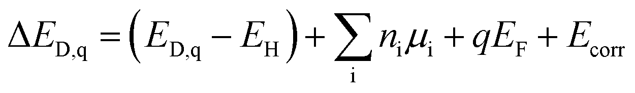 | (1) |
In total, we consider up to 31 different native defects comprising vacancies (VLi, VGe, VP, VS), anti-sites (GeP, PGe, PS, SP), and interstitials (Lii), with each unique Wyckoff site treated as a different defect. For each defect, charge states q = −3, −2, −1, 0, 1, 2, 3 are considered; for some defects, such as VP, additional charge states q = −5, −4, 4, 5 are also considered. The possible sites for Li interstitials are determined by a Voronoi tessellation scheme as implemented in the software, pylada-defects.40 In each structure, the energetically most favorable interstitial configuration is assessed by relaxing up to 50 different possible interstitial configurations.
The total energies of the supercells are calculated using the generalized gradient approximation (GGA) of Perdew–Burke–Ernzerhof (PBE)36 within the projector augmented wave (PAW) formalism as implemented in the VASP code.41 The total energies are calculated with a plane-wave energy cutoff of 340 eV and a Γ-centered 4 × 4 × 2 Monkhorst pack k-point grid to sample the Brillouin zone. The positions of the ions in the defect supercells are relaxed following a similar procedure used in ref. 15 and 42. The elemental chemical potentials μi are expressed relative to those of the elements in reference elemental phases as μi = μ0i + Δμi, where μ0i is the reference chemical potential under standard conditions and Δμi is the deviation from the reference. Δμi = 0 corresponds to i-rich conditions. For example, ΔμS = 0 (S-rich) corresponds to the equilibrium between LGPS and solid S. The reference chemical potentials (μ0i) are fitted to a set of measured formation enthalpies of compounds, as implemented in the FERE approach.43
The finite-size corrections included in Ecorr, following the methodology in ref. 39, are: (1) image charge correction for charged defects, (2) potential alignment correction for charged defects, (3) band filling correction for shallow defects, and (4) correction of band edges for shallow acceptors/donors. The calculations are organized and the results are analyzed using our software package, pylada-defects, for automation of point defect calculations.40
The underestimation of the band gap in DFT is remedied by applying individual valence and conduction band edge shifts (relative to the DFT-computed band edges) as determined from GW quasi-particle energy calculations.39 We use DFT wave functions as input to the GW calculations. The GW eigen-energies are iterated to self-consistency to remove the dependence on the single-particle energies of the initial DFT calculation. The input DFT wave functions are kept constant during the GW calculations, which allows the interpretation of the GW quasi-particle energies in terms of energy shifts relative to the DFT Kohn–Sham energies. The GW quasi-particle energies are calculated for the 50 atom cells using a 4 × 4 × 2 k-point grid.
Under a given growth condition, the equilibrium EF is determined by solving the charge neutrality condition. The concentration of defects are determined using Boltzmann distribution, such that [Dq] = Ns![[thin space (1/6-em)]](https://www.rsc.org/images/entities/char_2009.gif) exp(−ΔHD,q/kBT), where [Dq] is the defect concentration, Ns is the concentration of lattice sites where the defect can be formed, kB is the Boltzmann constant, and T is the temperature. At a given T, the concentrations of electrons and holes are functions of EF. To establish charge neutrality, the total positive charges should equal the negative charges. In this equation, EF is the only free parameter. By solving charge neutrality condition self-consistently, we can determine the equilibrium EF and the relevant defect formation energies and concentrations.
exp(−ΔHD,q/kBT), where [Dq] is the defect concentration, Ns is the concentration of lattice sites where the defect can be formed, kB is the Boltzmann constant, and T is the temperature. At a given T, the concentrations of electrons and holes are functions of EF. To establish charge neutrality, the total positive charges should equal the negative charges. In this equation, EF is the only free parameter. By solving charge neutrality condition self-consistently, we can determine the equilibrium EF and the relevant defect formation energies and concentrations.
2.3 Phase stability
The phase stability of LGPS relative to decomposition into competing phases determines the bounds on the values of Δμi, described in the Section 2.2. To establish the phase stability region of LGPS in the quaternary Li–Ge–P–S chemical potential phase space, we consider all known compounds in this chemical space reported in the Inorganic Crystal Structure Database (ICSD).44 We also consider additional LixPySz compounds suggested in ref. 32 and 33, which were compiled by Holzwarth et al.45 We find that the phase stability region of LGPS in the chemical potential space (in the absence of electrical bias) is bounded by 10 four-phase corners – at each corner LGPS is in equilibrium with 3 other phases. Overall, we find that LGPS is in equilibrium with S, Li3PS4, Li4GeS4, Li2S, GeS2, GeP3, and LiP7, which is in excellent agreement with the experimental phase diagrams of LGPS.46,47 In ref. 28, LGPS is predicted to be in equilibrium with S, Li2S, Li2GeS3, and Li2PS3, which does agree well with the experimental phase diagrams. More details of our phase stability calculation and the values of μ0i and Δμi of Li, Ge, P, and S at the 10 four-phase corners (labelled P-1 through P-10) are provided in the ESI.† Corners P-1 through P-4, which are in equilibrium with elemental S, represent the most sulfur-rich conditions while P-9 and P-10, which are in equilibrium with Li2S, are the most Li-rich conditions within the phase stability region.3 Results
Fig. 3 shows the four LGPS structures that were selected from the electrostatic energy minimization criterion followed by ensemble statistics, as described in Section 2.1. The structures differ in the occupation of the Li sites, most noticeably in the c-axis channels. The four structures exhibit slightly different cell volumes (Section 2.1). For each of these four structures, we computed their accurate electronic structure with GW-based methods and native defect energetics with first-principles defect calculations, which are discussed next.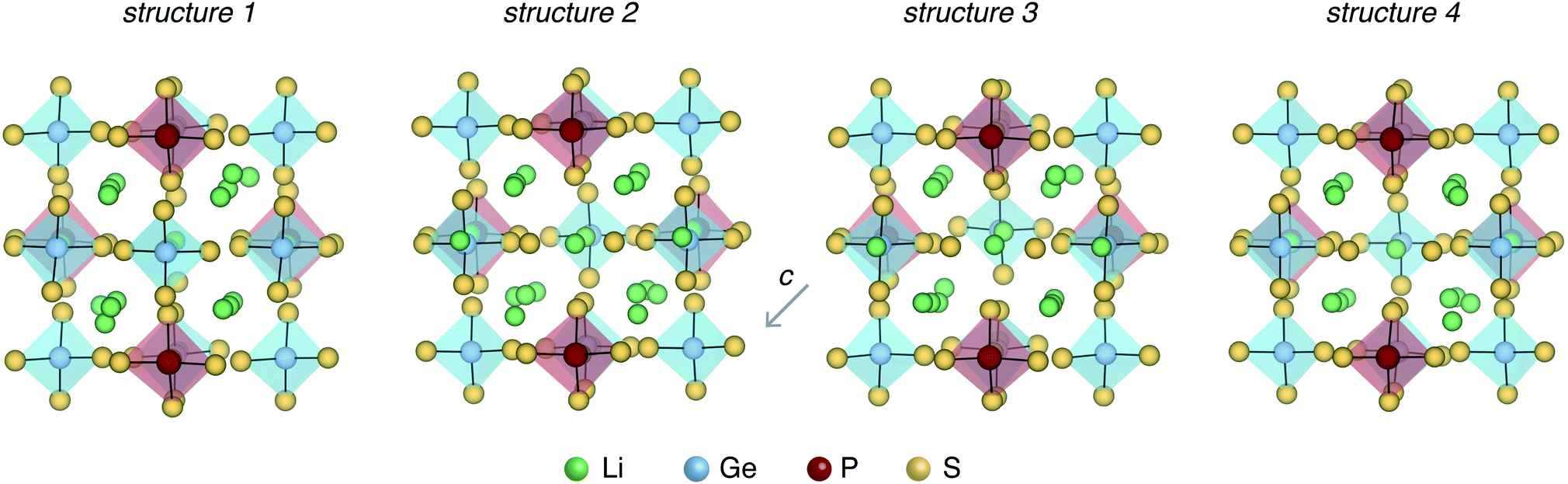 | ||
| Fig. 3 Four representative LGPS structures selected for defect calculations. The structures differ in the Li site occupations and have slightly different volumes per atom (19.74, 19.84, 19.94, 20.02 Å3 per atom). | ||
3.1 Electronic structure and defect chemistry of LGPS
Defect formation energies, and therefore, defect and electronic carrier concentrations are sensitive to the electronic structure, particularly the band gap. We calculated the band gap of the four structures (Fig. 3) and found them to range between 4.69–4.72 eV. Our GW-calculated band gaps are larger compared to the band gap calculated with hybrid DFT functional HSE06 (3.6–3.8 eV).28,32,33 GW-based methods are considered state-of-the-art for calculating the electronic structure of semiconductors and insulators.48 To the best of our knowledge, the GW electronic structure of LGPS has not been reported in the literature so far. Given the larger GW band gap, it is likely that the band gaps calculated with HSE06 are also underestimated; this could explain, in part, the discrepancy in the predicted and experimental electrochemical stability of LGPS discussed in ref. 32 and 33.Defect energetics are typically presented in the form of “defect diagrams” with defect formation energies (ΔED,q) plotted as functions of the Fermi energy (EF), as shown in Fig. 4. Defects with positive slopes are donors and with negative slopes are acceptors. The defect formation energies are also functions of the elemental chemical potentials μi (see eqn (1)). In other words, ΔED,q also depends on Δμi of each element in the Li–Ge–P–S quaternary phase space, where the values of Δμi are bound by the condition of LGPS phase stability (Section 2.3). As such, the defect diagrams are a function of the elemental chemical potentials.
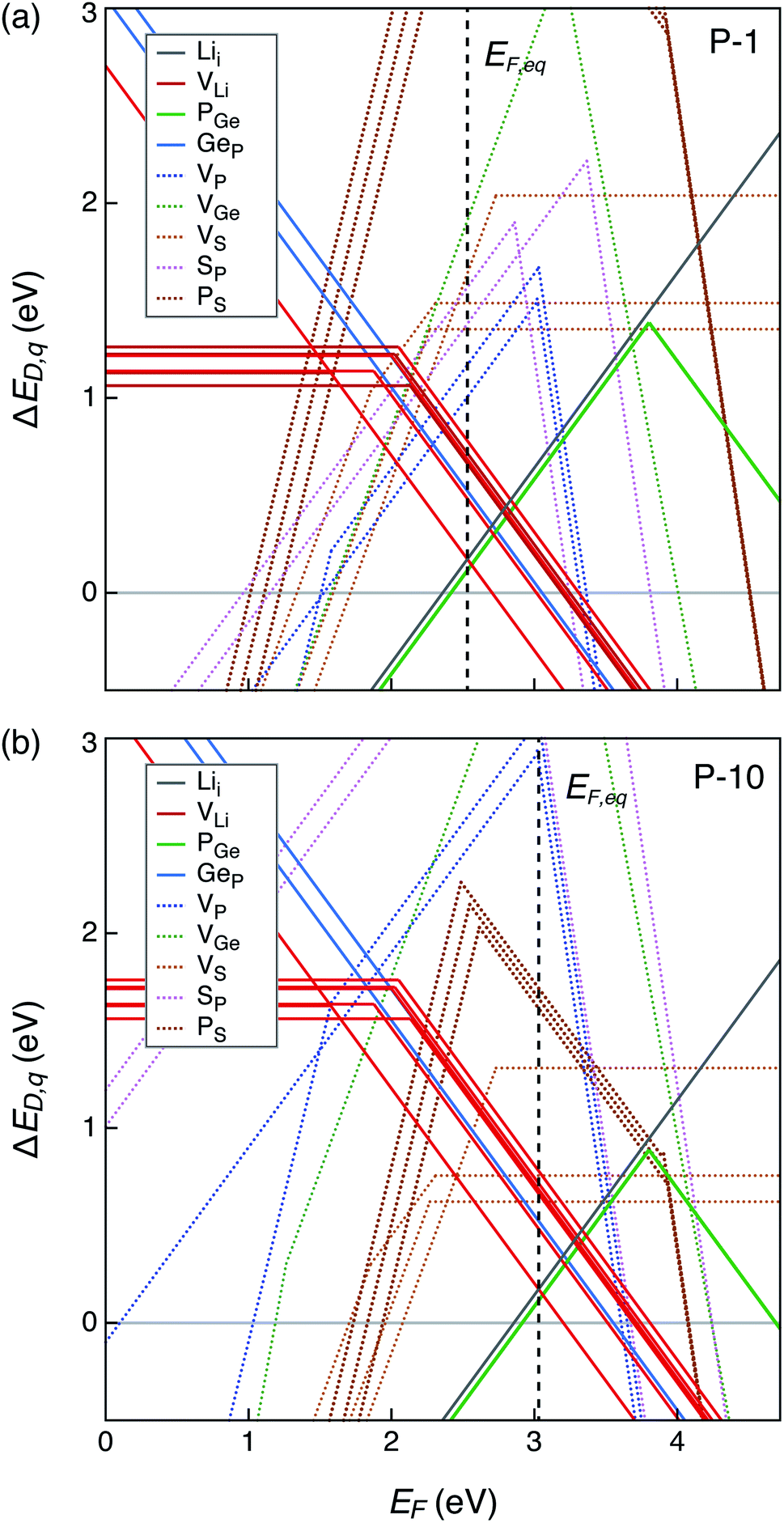 | ||
| Fig. 4 Formation energies of native point defects (ΔED,q) in Li10GeP2S12 as functions of Fermi energy (EF) at elemental chemical potentials corresponding to (a) P-1, and (b) P-10 (see Table S1†). EF is referenced to the valence band maximum. The upper limit of EF shown is the conduction band minimum such that EF values range from 0 to the band gap. Multiple lines of the same color represent the same defect type at different Wyckoff sites. Lowest formation energy defects are denoted by solid lines while those with higher formation energies with dotted lines. The equilibrium Fermi energy (EF,eq) marked by vertical dashed line is calculated at 300 K. | ||
Let us first examine the calculated defect energetics of one of the structures, namely structure 1 (Fig. 4). The defect energetics of structures 2–4 are qualitatively similar to that of structure 1. For the sake of simplicity, the defect energetics corresponding to the chemical potentials at two 4-phase corners (P-1 and P-10) are plotted in Fig. 4(a) and (b), respectively. The values of Δμi (i = Li, Ge, P, S) corresponding to the corners P-1 and P-10 are tabulated in the ESI.† The defects with the lowest formation energies at the equilibrium Fermi energy (EF,eq) are the dominant defects. In Fig. 4(a) and (b), we find that the dominant defects (denoted by solid lines) are Li vacancies (VLi), Li interstitials (Lii), and P1/Ge anti-sites (PGe). The Li vacancy with lowest formation energy forms at a Li site in the c-axis channel, as opposed to in the a–b plane bridging sites. The formation of PGe anti-site defects are more favorable than the formation of GeP anti-sites. Therefore, we predict that LGPS is naturally off-stoichiometric (slightly P-rich) compared to the ideal stoichiometry of P:Ge = 2:1. The predicted EF,eq is pinned around 2.56 (3.06) eV above the valence band maximum (EF = 0 eV) at corner P-1 (P-10). Owing to the large band gap and Fermi energy pinning far from the band edges, the predicted free carrier concentrations are very low, consistent with the fact that LGPS is electrically insulating.
The defect energetics of the dominant defects for structures 1–4 at corners of the phase stability region corresponding to P-1 and P-10 are summarized in Fig. 5. In all cases, the dominant defects are VLi, Lii, and PGe; higher energy anti-site defects GeP (at site P1) are also shown. While the formation energies of the dominant defects in a given structure do not vary significantly between corners P-1 and P-10, there is appreciable differences in the formation energetics between different structures. The variation in the formation energy of defects between different representative structures (structures 1–4) provides a quantitative measure of the statistical distribution of defect formation energies in the disordered LGPS phase. The variation in defect formation energies is further discussed in Section 4.
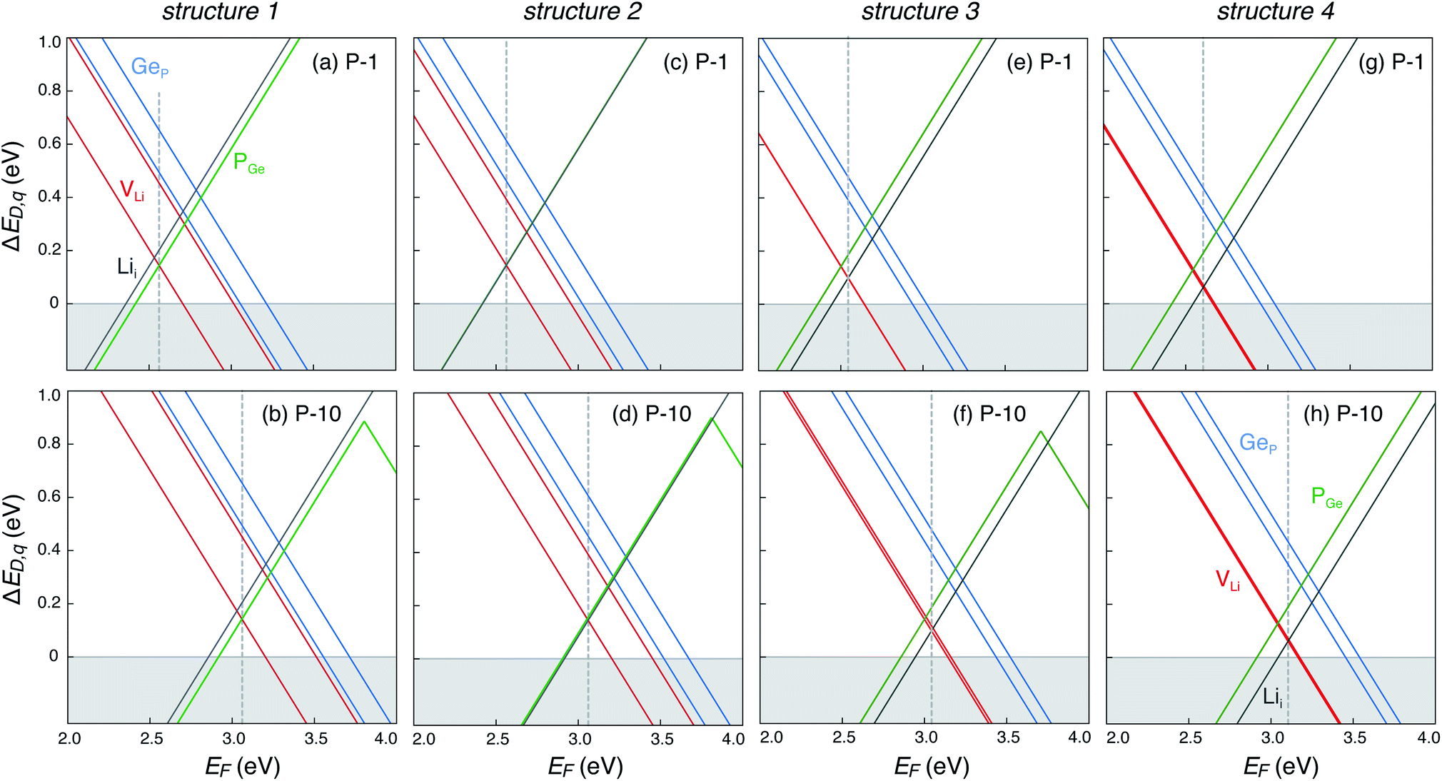 | ||
| Fig. 5 Formation energies of native point defects (VLi, Lii, PGe, and GeP) as functions of Fermi energy (EF) in LGPS structures 1–4 (Fig. 3) at elemental chemical potentials corresponding to P-1 (a, c, e and g), and P-10 (b, d, f and h). EF is referenced to the valence band maximum. Multiple lines of the same color represent the same defect type at different Wyckoff sites. | ||
4 Discussion
Thus far, we have shown that (1) the dominant defects in LGPS are VLi, Lii, and PGe, and (2) there is a distribution of defect formation energies within the ensemble of representative structures. In this section, we discuss the fundamental and practical implications of these findings for solid-state electrolytes.4.1 Dominant defects and distribution of defect energetics
The dominant defects in LGPS do not block the path of Li ion diffusion in the c-axis channels. In addition to a soft anion sub-lattice31 and cation site disorder,13 the absence of path-blocking defects could be another reason for the remarkably high Li ion conductivities in LGPS and related compounds.3,30 This is unlike certain cathode materials, such as LiFePO4, where path-blocking, anti-site defects FeLi are present in high concentrations.23Fig. 6 shows the distribution of the formation energies (at the equilibrium Fermi energy) of the relevant defects in LGPS. For a given defect type, the spread in the formation energies arises from two sources: (1) variation with elemental chemical potentials μi (or Δμi), and (2) variations between structures 1–4. We observe that the spread in the defect formation energies range from ∼60 meV (PGe) to up to 140 meV (Lii). At the synthesis temperature (823 K), the spread in the formation energies translate into a spread in the defect concentrations of 1.2 × 10²⁰ to 2.7 × 1020 cm−3 for PGe and 8.8 × 10¹⁹ to 3.9 × 1020 cm−3 for Lii. Therefore, in the disordered phase of LGPS, one can expect the defect concentrations to be an average over the corresponding defect concentrations in the representative structures. However, given the higher probability of structures 1 and 2 (Fig. 2), compared to structures 3 and 4, the defect energetics from s1 and s2 can be expected to be statistically more significant. Nonetheless, the spread in the defect formation energies in Fig. 6 is significant, which emphasizes the need to consider an ensemble of probable structures to estimate the defect energetics in the disordered phase (as opposed to a single ordered representation).
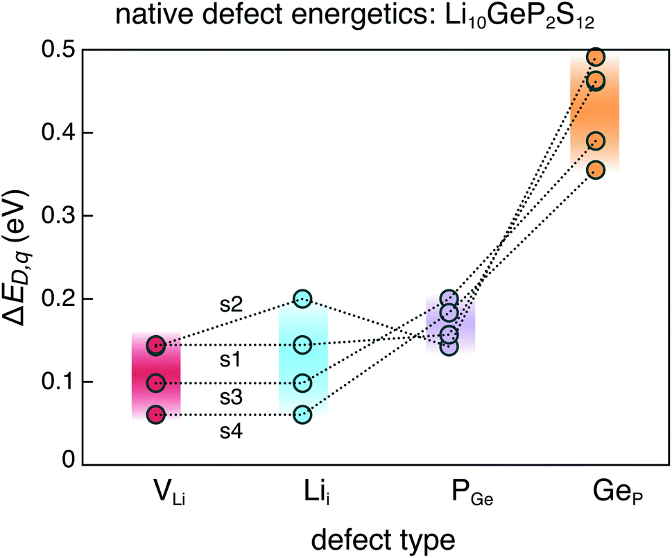 | ||
| Fig. 6 Range of formation energies of native defects (VLi, Lii, PGe, GeP) in the ensemble of four representative LGPS structures (s1–s4). | ||
Additionally, the lower formation energy of PGe anti-site defects compared to GeP suggests that nominally stoichiometric composition Li10GeP2S12 will be slightly P-rich. Experimental studies have shown that LGPS forms Ge-rich solid solutions in the Li4GeS4–Li3PS4 pseudo-binary phase diagram.46,49 The same study found that the nominally stoichiometric LGPS composition can be slightly P-rich at typical growth temperatures around 823 K, consistent with our findings.
4.2 Conductivity enhacement by anti-site defects
A previous study used ab initio molecular dynamics simulations and found that PGe anti-site defects in LGPS enhance Li ion conductivity.28 A plausible explanation for the conductivity enhancement can be gleaned from the local structure around the PGe anti-site defects. It is known that Ge–S bonds (2.1 Å) are slightly longer than P–S bonds (2.0 Å),3 which makes the S anion sub-lattice deviate from the ideal bcc framework,50 leading to distortion of the c-axis channel as shown in Fig. S1 (ESI).† The introduction of PGe anti-site defect appears to locally restore the bcc framework and make the c-axis channel less distorted, as shown for one of the structures with PGe defect (Fig. S1†). It is plausible that the removal of structural distortion locally enhances Li ion conductivity.Therefore, it would be prudent to synthesize LGPS under growth conditions that maximize the concentration of these anti-site defects. To this end, we identify the chemical potentials (within the phase stability region) corresponding to the most P-rich/Ge-poor conditions such that the defect formation energy of PGe is minimized. This is achieved at the chemical potentials corresponding to the 4-phase corner P-9 (see Table S1 in ESI†). At P-9, LGPS is in equilibrium with Li3PS4, Li2S, and LiP7. In practice, this can be achieved in experiments by performing phase boundary mapping.42 For instance, synthesizing LGPS such that trace amounts of Li3PS4, Li2S, and LiP7 are present will ensure that chemical potentials during growth are at corner P-9. Phase boundary mapping has been successfully utilized to engineer thermoelectric materials, where charge transport appears to be largely unaffected by the trace amounts of impurity phases.42 However, in solid-state conductors, it is possible that such impurity phases may hinder ion conduction.
Among others, experimental efforts to replace Ge as well as improve the Li ion conductivity in LGPS have involved alloying on the Ge site with Group 14 elements (Si, Sn).30,51–53 However, those studies have revealed that the Li ion conductivity in the solid solutions (with Si, Sn) are somewhat lower than in LGPS. Our defect calculations provide insights about the native defect chemistry of LGPS in the non-interacting dilute limit; however, the defect chemistry in highly off-stoichiometric and solid solutions of LGPS cannot be inferred from our calculations because the non-interacting dilute approximation is not valid in such cases.
5 Conclusions
To understand and find ways to improve ionic conductivity of solid-state electrolytes, it is important to fully investigate the defect energetics and the effect of defects on ionic conductivity. Computing the defect energetics in disordered phases is particularly challenging. Here, we modeled the native defect chemistry of a disordered solid-state electrolyte, Li10GeP2S12, by employing a unique methodology. The results provide insights into the fundamental understanding of defect properties and experimental guidance to improve ionic conductivity in LGPS. To summarize,(1) The dominant defects in LGPS are VLi, Lii, and PGe. Anti-site GeP defects are present in concentrations lower than PGe.
(2) Anti-site PGe defects enhance Li ion conductivity plausibly due to the removal of local structural distortion.
(3) Synthesis of LGPS under P-rich/Ge-poor growth conditions will maximize concentration of PGe, thereby improving ionic conductivity. LGPS grown in equilibrium with Li3PS4, Li2S, and LiP7 will be most P-rich/Ge-poor.
The calculation methodology presented in this work lays the groundwork to investigate the defect properties of other well-known and emerging disordered solid-state electrolytes.
Conflicts of interest
There are no conflicts to declare.Acknowledgements
We want to thank the peer reviewers whose comments and suggestions have helped improve and clarify this manuscript. The work was authored by the National Renewable Energy Laboratory (NREL), operated by Alliance for Sustainable Energy, LLC, for the U.S. Department of Energy (DOE) under Contract No. DE-AC36-08GO28308. Funding provided by the Laboratory Directed Research and Development (LDRD) program at NREL. The research was performed using computational resources sponsored by the Department of Energy's Office of Energy Efficiency and Renewable Energy and located at the National Renewable Energy Laboratory. The views expressed in this article do not necessarily represent the views of the DOE or the U.S. Government.References
- A. Manthiram, X. Yu and S. Wang, Nat. Rev. Mater., 2017, 2, 16103 CrossRef CAS
.
- T. Famprikis, P. Canepa, J. A. Dawson, M. S. Islam and C. Masquelier, Nat. Mater., 2019, 18, 1278–1291 CrossRef CAS PubMed
- N. Kamaya, K. Homma, Y. Yamakawa, M. Hirayama, R. Kanno, M. Yonemura, T. Kamiyama, Y. Kato, S. Hama and K. Kawamoto,
et al.
, Nat. Mater., 2011, 10, 682 CrossRef CAS PubMed
- P. Bron, S. Johansson, K. Zick, J. Schmedt auf der Günne, S. Dehnen and B. Roling, J. Am. Chem. Soc., 2013, 135, 15694 CrossRef CAS PubMed
- V. Thangadurai, S. Narayanan and D. Pinzaru, Chem. Soc. Rev., 2014, 43, 4714 RSC
- Q. Liu, Z. Geng, C. Han, Y. Fu, S. Li, Y. bing He, F. Kang and B. Li, J. Power Sources, 2018, 389, 120 CrossRef CAS
- H.-J. Deiseroth, S.-T. Kong, H. Eckert, J. Vannahme, C. Reiner, T. Zaib and M. Schlosser, Angew. Chem., Int. Ed., 2008, 47, 755 CrossRef CAS PubMed
- M. Chen and S. Adams, J. Solid State Electrochem., 2015, 19, 697 CrossRef CAS
- T. Kobayashi, Y. Imade, D. Shishihara, K. Homma, M. Nagao, R. Watanabe, T. Yokoi, A. Yamada, R. Kanno and T. Tatsumi, J. Power Sources, 2008, 182, 621 CrossRef CAS
- W. Zhou, Y. Li, S. Xin and J. B. Goodenough, ACS Cent. Sci., 2017, 3, 52 CrossRef CAS PubMed
- R. Mouta, M. A. B. Melo, E. M. Diniz and C. W. A. Paschoal, Chem. Mater., 2014, 26, 7137 CrossRef CAS
- Y. Zhao and L. L. Daemen, J. Am. Chem. Soc., 2012, 134, 15042 CrossRef CAS PubMed
- I. Hanghofer, M. Brinek, S. L. Eisbacher, B. Bitschnau, M. Volck, V. Hennige, I. Hanzu, D. Rettenwander and H. M. R. Wilkening, Phys. Chem. Chem. Phys., 2019, 21, 8489 RSC
- S. Saha, G. Rousse, F. Fauth, V. Pomjakushin and J.-M. Tarascon, Inorg. Chem., 2019, 58, 1774 CrossRef CAS PubMed
- P. Gorai, B. Ortiz, E. S. Toberer and V. Stevanovic, J. Mater. Chem. A, 2018, 6, 13806 RSC
- B. Ortiz, P. Gorai, V. S. Stevanović and E. S. Toberer, Chem. Mater., 2017, 29, 4523 CrossRef CAS
- A. Janotti and C. G. Van de Walle, Phys. Rev. B: Condens. Matter Mater. Phys., 2007, 76, 165202 CrossRef
- I. Chatratin, F. P. Sabino, P. Reunchan, S. Limpijumnong, J. B. Varley, C. G. Van de Walle and A. Janotti, Phys. Rev. Mater., 2019, 3, 074604 CrossRef CAS
- S. Lany, APL Mater., 2018, 6, 046103 CrossRef
- P. Gorai, R. W. McKinney, N. M. Haegel, A. Zakutayev and V. Stevanovic, Energy Environ. Sci., 2019, 12, 3338 RSC
- S.-H. Bo, Y. Wang, J. C. Kim, W. D. Richards and G. Ceder, Chem. Mater., 2016, 28, 252 CrossRef CAS
- P. Canepa, G. Sai Gautam, D. Broberg, S.-H. Bo and G. Ceder, Chem. Mater., 2017, 29, 9657 CrossRef CAS
- J. Lee, W. Zhou, J. C. Idrobo, S. J. Pennycook and S. T. Pantelides, Phys. Rev. Lett., 2011, 107, 085507 CrossRef PubMed
- N. Kuganathan and M. S. Islam, Chem. Mater., 2009, 21, 5196 CrossRef CAS
- Y. Koyama, H. Arai, I. Tanaka, Y. Uchimoto and Z. Ogumi, Chem. Mater., 2012, 24, 3886 CrossRef CAS
- J. Pan, J. Cordell, G. J. Tucker, A. C. Tamboli, A. Zakutayev and S. Lany, Adv. Mater., 2019, 31, 1807406 CrossRef PubMed
- L. L. Baranowski, K. McLaughlin, P. Zawadzki, S. Lany, A. Norman, H. Hempel, R. Eichberger, T. Unold, E. S. Toberer and A. Zakutayev, Phys. Rev. Appl., 2015, 4, 044017 CrossRef
- K. Oh, D. Chang, B. Lee, D.-H. Kim, G. Yoon, I. Park, B. Kim and K. Kang, Chem. Mater., 2018, 30, 4995 CrossRef CAS
- A. G. Squires, D. O. Scanlon and B. J. Morgan, Chem. Mater., 2020 DOI:10.1021/acs.chemmater.9b04319
- Y. Kato, S. Hori, T. Saito, K. Suzuki, M. Hirayama, A. Mitsui, M. Yonemura, H. Iba and R. Kanno, Nat. Energy, 2016, 1, 16030 CrossRef CAS
- D. A. Weber, A. Senyshyn, K. S. Weldert, S. Wenzel, W. Zhang, R. Kaiser, S. Berendts, J. Janek and W. G. Zeier, Chem. Mater., 2016, 28, 5905 CrossRef CAS
- S. P. Ong, Y. Mo, W. D. Richards, L. Miara, H. S. Lee and G. Ceder, Energy Environ. Sci., 2013, 6, 148 RSC
- Y. Mo, S. P. Ong and G. Ceder, Chem. Mater., 2012, 24, 15 CrossRef CAS
- S. Adams and R. Prasada Rao, J. Mater. Chem., 2012, 22, 7687 RSC
- A. Kuhn, J. Kohler and B. V. Lotsch, Phys. Chem. Chem. Phys., 2013, 15, 11620 RSC
- J. P. Perdew, K. Burke and M. Ernzerhof, Phys. Rev. Lett., 1996, 77, 3865 CrossRef CAS PubMed
- E. Jones and V. Stevanovic, arXiv:1902.05939, 2019.
- R. F. Moran, D. McKay, P. C. Tornstrom, A. Aziz, A. Fernandes, R. Grau-Crespo and S. E. Ashbrook, J. Am. Chem. Soc., 2019, 141, 17838 CrossRef CAS PubMed
- S. Lany and A. Zunger, Phys. Rev. B: Condens. Matter Mater. Phys., 2008, 78, 235104 CrossRef
- A. Goyal, P. Gorai, H. Peng, S. Lany and V. S. Stevanović, Comput. Mater. Sci., 2016, 130, 1 CrossRef
- G. Kresse and J. Furthmüller, Phys. Rev. B: Condens. Matter Mater. Phys., 1996, 54, 11169 CrossRef CAS PubMed
- S. Ohno, K. Imasato, S. Anand, H. Tamaki, S. D. Kang, P. Gorai, H. K. Sato, E. S. Toberer, T. Kanno and G. J. Snyder, Joule, 2017, 2, 141 CrossRef
- V. Stevanović, S. Lany, X. Zhang and A. Zunger, Phys. Rev. B: Condens. Matter Mater. Phys., 2012, 85, 115104 CrossRef
- A. Belsky, M. Hellenbrandt, V. L. Karen and P. Luksch, Acta Crystallogr., Sect. B: Struct. Sci., 2002, 58, 364 CrossRef PubMed
- N. Holzwarth, N. Lepley and Y. A. Du, J. Power Sources, 2011, 196, 6870 CrossRef CAS
- S. Hori, M. Kato, K. Suzuki, M. Hirayama, Y. Kato and R. Kanno, J. Am. Ceram. Soc., 2015, 98, 3352 CrossRef CAS
- F. Han, Y. Zhu, X. He, Y. Mo and C. Wang, Adv. Energy Mater., 2016, 6, 1501590 CrossRef
- H. Peng, D. O. Scanlon, V. Stevanovic, J. Vidal, G. W. Watson and S. Lany, Phys. Rev. B: Condens. Matter Mater. Phys., 2013, 88, 115201 CrossRef
- R. Iwasaki, S. Hori, R. Kanno, T. Yajima, D. Hirai, Y. Kato and Z. Hiroi, Chem. Mater., 2019, 31, 3694 CrossRef CAS
- Y. Wang, W. D. Richards, S. P. Ong, L. J. Miara, J. C. Kim, Y. Mo and G. Ceder, Nat. Mater., 2015, 14, 1026 CrossRef CAS PubMed
- Y. Sun, K. Suzuki, S. Hori, M. Hirayama and R. Kanno, Chem. Mater., 2017, 29, 5858 CrossRef CAS
- S. Hori, K. Suzuki, M. Hirayama, Y. Kato, T. Saito, M. Yonemura and R. Kanno, Faraday Discuss., 2014, 176, 83 RSC
- S. Hori, K. Suzuki, M. Hirayama, Y. Kato and R. Kanno, Front. Energy Res., 2016, 4, 38 Search PubMed
Footnote |
| † Electronic supplementary information (ESI) available. See DOI: 10.1039/c9ta10964a |
| This journal is © The Royal Society of Chemistry 2020 |