
Construction of a hierarchical micro & nanoporous surface for loading genistein on the composite of polyetheretherketone/tantalum pentoxide possessing antibacterial activity and accelerated osteointegration
Shiqi
Mei
 a,
Fan
Wang
a,
Xinglong
Hu
a,
Kong
Yang
*b,
Dong
Xie
c,
Lili
Yang
c,
Zhaoying
Wu
d and
Jie
Wei
*a
a,
Fan
Wang
a,
Xinglong
Hu
a,
Kong
Yang
*b,
Dong
Xie
c,
Lili
Yang
c,
Zhaoying
Wu
d and
Jie
Wei
*a
aKey Laboratory for Ultrafine Materials of Ministry of Education, East China University of Science and Technology, Shanghai 200237, China. E-mail: jiewei7860@sina.com
bInstitute of Qinghai-Tibetan Plateau, Southwest Minzu University, Chengdu 610064, China. E-mail: lx-yk@163.com
cDepartment of Orthopaedic Surgery, Changzheng Hospital, Second Military Medical University, Shanghai 200003, China
dSchool of Biomedical Engineering, Sun Yat-sen University, Guangzhou, Guangdong 510006, China
First published on 26th October 2020
Abstract
Nanoporous tantalum pentoxide (NTP) particles with a pore size of about 10 nm were synthesized and blended with polyetheretherketone (PEEK) to fabricate a PEEK/NTP composite (PN). Subsequently, PN was treated by concentrated sulfuric acid to create a microporous surface (pore size of around 2 μm) on sulfonated PN (SPN), which formed a hierarchical micro & nanoporous surface. Compared with PN, the porous surface of SPN exhibited higher roughness, hydrophilicity, and surface energy. In addition, genistein (GT) was loaded into the porous surface of SPN (SPNG), which showed high GT loading capacity and sustained release of GT into phosphate buffered saline (PBS). Moreover, SPNG revealed excellent antibacterial activity, which inhibited bacterial (E. coli and S. aureus) growth in vitro due to the synergistic effects of both sulfonic acid (SO3H) groups and the sustained release of GT. Compared with PN, SPN significantly improved the adhesion, proliferation, and osteogenic differentiation of bone mesenchymal stem cells in vitro. Moreover, compared with SPN, SPNG further enhances the cell responses. Compared with PN, SPN remarkably improved bone formation and osteointegration in vivo. Furthermore, compared with SPN, SPNG further enhanced the osteointegration. In short, SPNG with a micro & nanoporous surface, SO3H groups, and the sustained release of GT exhibited antibacterial activity and accelerated osteointegration, which would have tremendous potential as drug-loaded implants for bone substitute.
1. Introduction
Polyetheretherketone (PEEK) is a high-performance polymeric material applied for biomedical implants due to its outstanding mechanical properties and biocompatibility as well as corrosion resistance.1 As biomedical implants, PEEK is primarily applied as an intervertebral cage for spinal fusion; it has also been developed for prosthodontics, trauma, cranial, and maxillofacial implants.2 As a biocompatible and biostable material, PEEK elicits no toxic, inflammatory, or mutagenic responses in the human body.2,3 In addition, the elastic modulus of PEEK is close to the cortical bone of humans, a feature that has been broadly developed in implants to reduce stress shielding, and thus, bone resorption.4 The key to success of the implant is the formation of stable osseointegration between the implantable material and the bone interface, which directly impact the initial and long-term stability of the implant.3,5 Therefore, good osteointegration performance is necessary for a permanent orthopedic device. Notwithstanding these outstanding performances of PEEK, however, it is a non-degradable and bioinert polymer that exhibits no bioactivity.1,3,6 It has been reported that fibrous encapsulation was formed around the PEEK implants, and the layer of fibrous tissue generated at the interface between the bioinert implants and host bone would cause no osteointegration, which further lead to the loosening and failure of the implant.7The shortcomings of PEEK are a consequence of the combination of its hydrophobic features and interactions of specific molecules between the cells and the structure of PEEK in the bio-environment.1,8 As a result, the functionalization of PEEK to concurrently improve the osteogenic performances and antibacterial activity is being actively investigated to develop a new generation of spinal, trauma, maxillofacial and cranial, and prosthodontic implants.6,9 Some strategies including surface functionalization and composites have been utilized to boost the bioactivity and antibacterial activity of PEEK.2,9 The surface functionalization of PEEK has been achieved by changing its surface chemical composition and topological structure by using chemical/physical methods (polishing, mechanical roughening, texturing, and coatings).6,10 In addition, PEEK composites have been created by incorporating functional particles that supply PEEK with osteogenic performances and antibacterial activity.11 The strategy of obtaining bioactive composites through the addition of bioactive materials into PEEK exhibits great potential to enhance the performance of bulk PEEK (including mechanical and bioactive properties); however, the surface osteogenic performances and antibacterial activity of these composites show low levels.3,9 Therefore, the further improvement of the surface biological performances of the composites is required.10,11 To address this challenge, incorporating drugs onto the implant surface to accelerate bone formation and osseointegration have been paid more attention.12
Biomaterial-related infection results from the decreased immune resistance of the host following surgical trauma and the material itself acting as a foreign body, which increases the risk of infection by promoting the entry as well as proliferation of microorganisms, is another main reason for the failure of implants.13 In particular, the infection of biomaterial-adjacent bone tissues causes the receding of the surrounding tissue on-growth, the subsequent reduction of the biomechanical anchorages of implantable materials, and finally, the failure of implants.14 Therefore, the prevention of bacterial adhesion, which causes the formation of a biofilm on the implantable material, is an essential initial step in avoiding bacterial infection.15 PEEK with no bioactivity is prone to bacterial colonization and biofilm formation as well as periprosthetic infections.14,15
Recently, tantalum (Ta) metal has attracted much attention of researchers because of its excellent biocompatibility and corrosion resistance as well as bioactivity for promoting cell response/bone tissue in-growth capabilities.16 Ta is regarded as one of the most promising implantable materials, which is commonly applied as a porous implant for bone repair, cranioplasty plates, artificial joints, meshes for nerve repair, and radiopaque markers.17 It has been suggested that a natural thin layer of tantalum pentoxide (Ta2O5) existing on the Ta surface would play pivotal roles in its excellent biocompatibility and bioactivity as well as corrosion resistance.17,18 In previous studies, Ta2O5 has been coated on titanium, which exhibited excellent biocompatibility, bioactivity, osseointegration ability, high hardness, and good wear resistance.18 A previous study has shown that the Ta2O5 coating enhanced the biocompatibility, anticorrosion, and antibacterial activity of the NiTi alloy.19 Ta2O5 coatings on metallic Ta were introduced, which possessed outstanding characteristics with excellent adherence as well as low elastic modulus compared with that of metallic Ta.20 Ta2O5 was utilized as a dopant to enhance the hardness, toughness, and densification of alumina, the mechanical strength of bioglass, and the mechanical strength and crystallization of glass-ceramics.19 Ta2O5 has been added into hydroxyapatite and utilized alongside the calcium phosphate phase in layered coatings, which possesses high bioactivity.21 The noteworthy attributes of Ta2O5 (e.g., excellent corrosion resistance, biocompatibility, bioactivity, osseointegration ability, high wettability, and superb bio-stability) have improved the competency of this inorganic oxide material for bone repair.19,22
As we know, the topography of implantable materials plays key roles in mediating the interactions of the cell–substrate at the interface of the material-bone tissue, and surface micro- or nano-structure modification is widely applied to tailor the physical and chemical as well as biological performances of different implantable materials.6,23 The micro or nanoporous structure supplies more affinity to the cell/tissue growth, and thus enhances the initial and long-term stability of the implants in vivo.24 From a biomimetic viewpoint, developing a hierarchical micro & nanosurface same as the natural bone tissue possesses huge potential in stimulating the responses of the cell/tissue.23,24 Therefore, the trends in the topographical modification of implantable materials highlight the hierarchical micro & nanostructure to promote cell functions and to accelerate osseointegration.25 In the past few decades, nanoporous particles (pore sizes of 2–50 nm) have attracted remarkable attention for biomedical applications because of the features of a large specific surface area as well as large pore volume.26,27 Nanoporous materials have been developed as drug delivery systems for different therapeutic agents in order to fight against many diseases (such as cancer, diabetes, inflammation, as well as tissue disease).27
Genistein (GT) is one of the major isoflavones, which is found in unprocessed soybeans. GT possesses several biofunctions of anti-microbial, anti-inflammatory, anti-oxidant, and anti-carcinogenic effects.28 GT not only promotes osteoblastic differentiation and mineralization but also inhibits osteoclast formation and bone resorption of osteoclasts.29 In this study, nanoporous tantalum pentoxide (NTP) submicron particles were synthesized and blended with polyetheretherketone (PEEK) to fabricate a composite of PEEK/NTP (PN). Moreover, the surface of PN was treated with concentrated sulfuric acid to fabricate the microporous surface containing NTP on sulfonated PN (SPN) and the loaded drug of GT (SPNG). The objective of this study was to create a hierarchical micro & nanoporous surface on SPN, and to construct a GT-loaded implant of SPNG which possesses antibacterial activity and accelerating osteogenesis as well as osteointegration. Therefore, in comparison with PN, the surface features (such as roughness and hydrophilicity as well as the surface energy) of SPN were characterized, and the drug loading efficiency and release behavior of GT from SPN into phosphate buffered saline (PBS) were investigated. In addition, in comparison with PN and SPN, the antibacterial activity (E. coli and S. aureus) of SPNG was studied, and bone mesenchymal stem cell (BMSC) responses (adhesion, proliferation, alkaline phosphatase activity, and expression of osteogenic related genes/proteins) to SPNG was investigated in vitro. Furthermore, osteogenesis and osteointegration of SPNG were evaluated in vivo.
2. Experimental
2.1 Synthesis of NTP
NTP was synthesized by using PEO-PPO-PEO (P123, Sigma-Aldrich Co., USA) as a template agent for obtaining nanoporous structures through the sol–gel method. Briefly, 4 g P123 was dissolved in 120 mL HCl solution (2 mol L−1) and 30 mL deionized water, and then stirred for 6 hours until the solution was clear. Afterwards, 5 g TaCl5 (99.99%, Aladdin Biochemical Technology Co., China) was added into the solution and continuously stirred, and the reaction temperature was kept at 50 °C. After stirring for 5 hours, the suspended solution temperature was kept at 60 °C for 3 days and the products were obtained by filtration, which were washed by acetone, ethanol, and deionized water. Finally, the products were dried at 100 °C and then sintered at 600 °C for 6 hours to obtain the NTP particles, and the residual P123 was removed simultaneously.2.2 Preparation of PEEK, PN, SPK, and SPN
Cold pressing-sintering method was used to prepare the PEEK and PEEK/NTP composite (PN) samples for sulfonation treatment, while the untreated PEEK and PN samples were prepared as the control groups. PEEK powder (450G, VICTREX Co., UK) was added into the ethanol solution and stirred for 2 hours to obtain the PEEK dispersion. Moreover, PN powder (optimized proportion: PEEK/NTP = 50![[thin space (1/6-em)]](https://www.rsc.org/images/entities/char_2009.gif) :50, v/v) was obtained by the addition of NTP particles into the PEEK dispersion and continuously stirred for 4 hours. The dispersions of PEEK and PN were stood for 4 hours and then the supernatant was poured out, which was dried at 60 °C in a vacuum oven to get two types of powders. In addition, the powders were mixed by using a mixing machine (SYH-5, Xuanyu Co., China) to get well-distributed PEEK and PN powders.
:50, v/v) was obtained by the addition of NTP particles into the PEEK dispersion and continuously stirred for 4 hours. The dispersions of PEEK and PN were stood for 4 hours and then the supernatant was poured out, which was dried at 60 °C in a vacuum oven to get two types of powders. In addition, the powders were mixed by using a mixing machine (SYH-5, Xuanyu Co., China) to get well-distributed PEEK and PN powders.
The powders of PEEK and PN were placed into stainless-steel molds (Φ18 × 10 mm and Φ4 × 10 mm, respectively). Then, the molds were compressed using a pressure machine (769YP-60E, Jingsheng Co., China) with a pressure of 4 MPa to get one type of sample with Φ18 × 2 mm dimensions for characterization, drug loading, in vitro antibacterial and cell experiments, and another sample of Φ4 × 5 mm dimensions for in vivo animal experiments. The samples were sintered for 4 hours (optimized temperature: 343 °C for PEEK; 355 °C for PN), and then ground and polished by an automatic polishing machine (UNIPOL-1000S, Kejing Co., China) to make the surface smooth, followed by ultrasonic cleaning with ethanol, acetone, and deionized water to obtain the PEEK and PN samples.
Afterwards, the PEEK and PN samples were immersed in concentrated sulfuric acid (AR, Titan Scientific Co., China) at room temperature and the soaking time was preferably 15 minutes. Furthermore, the samples were immersed in deionized water for 5 minutes in order to remove the residual sulfuric acid on the surface. Owing to the high sulfur element content on the surface, hydrothermal treatment was carried out for PEEK and PN samples. Firstly, the samples were immersed into deionized water and packaged in 10 mL centrifuge tubes. Then, the samples were heated in an oil bath, while the reaction conditions were kept at 100 °C for 4 hours. Finally, sulfonated PEEK (SPK) and sulfonated PN (SPN) samples were obtained.
2.3 Characterization of NTP, PEEK, PN, SPK, and SPN
The morphology of NTP was characterized using scanning electron microscopy (SEM, GeminiSEM 500, ZEISS Co., Germany) and transmission electron microscopy (TEM, HT7800, Hitachi Co., Japan). The particle size of NTP was determined using dynamic light scattering (DLS, S3500, Microtrac Co., Germany). The N2 adsorption–desorption isotherm and specific surface area were measured by utilizing Brunauer–Emmett–Teller (BET, Tristar 3000, Micromeritics Instrument Co., USA) analysis, and the nanopore size distribution and nanopore volume were determined utilizing the Barrett–Joyner–Halenda isotherm (BJH, ASAP 2010, Micromeritics Instrument Co., USA) analysis.The surface morphology as well as the composition of NTP, PEEK, PN, SPK, and SPN were characterized using SEM, laser confocal microscopy (VK-X 110, Keyence Co., Japan), atomic force microscopy (AFM, DiMultiMode, Veeco Co., USA), Fourier transform infrared spectroscopy (FTIR, Frontier, PerkinElmer Co., USA), X-ray diffraction (XRD, D8 Advance, Bruker Co., Germany), and X-ray photoelectron spectroscopy (XPS, K-Alpha, Thermo Scientific Co., USA). The elemental composition of the samples (PEEK, PN, SPK, and SPN) was measured by utilizing energy dispersive spectrometry (EDS, GeminiSEM 500, ZEISS Co., Germany). The compressive strength of the samples was determined by applying a universal material machine (E44.304, MTS Co., China). The water and diiodomethane contact angles of the samples were determined using a droplet shape analyzer (DSA, DSA100, KRUSS Co., Germany). The surface energy of the samples was determined using the attached software of DSA.
2.4 Drug loading and release experiments
The SPK and SPN samples were placed into 10 mL centrifuge tubes, and 10 mL GT solution (1000 μg mL−1) was added into each centrifuge tube. The GT loading experiment was carried out at 37 °C in a bench thermostatic oscillator (YC-200D, Chengzao Co., China) for 24 hours to obtain the GT loading samples (SPKG and SPNG). Afterwards, 200 μL supernatant of each tube was taken and the OD values were measured using the enzymatic marker. The concentration of residual GT was calculated according to the standard GT curve. The loading efficiency of the samples was calculated by using the following formula:
| Loading efficiency (%) = (Mw − Mr)/Ms × 100% |
The GT and GT loading samples (SPKG and SPNG) prepared by the GT loading experiment were characterized by FTIR and XRD.
2.5 Antibacterial experiment in vitro
The antibacterial activity of five groups (PEEK, PN, SPK, SPN, and SPNG) of samples for Gram-negative Escherichia coli (E. coli, ATCC 8739) and Gram-positive Staphylococcus aureus (S. aureus, ATCC 6538) was evaluated by the count colony method. In an amicrobic atmosphere, the E. coli inoculated on nutrient agar surface and S. aureus inoculated on tryptone soybean agar surface were picked up by an inoculating loop on a super clean bench (refrigerated at about 4 °C), and dissolved in nutritious broth and tryptone soy broth, respectively, followed by culturing in a bacteriological incubator at 37 °C. 24 hours after culturing, 200 μL of the bacterial solutions were absorbed and then coated on a plate. Then, the bacterial solutions were cultured in the bacteriological incubator at 37 °C. When E. coli and S. aureus grew, the number of colonies was counted and the concentrate of bacterial solution was calculated. Afterwards, 10 μL of the bacterial solution was absorbed on the culture medium and the samples were added into the medium. The medium was cultured at 37 °C for 24 hours with humidity more than 90%. Finally, the culture medium was diluted and the bacterial colony on the medium was photographed, while the number of colonies was counted. The blank medium without the samples was set as the control group and the antibacterial ratio of the samples was calculated by using the following formula:| Antibacterial ratio (%) = (M − N)/M × 100% |
2.6 Cell experiments in vitro
Based on the evaluation of drug loading and in vitro antibacterial experiments, four groups samples (PEEK, PN, SPN, and SPNG) were optimized, and the cytocompatibility of the samples was determined by BMSC (isolated from the femurs of rats). UV radiation and 75% ethanol were utilized to sterilize the samples, followed by placing the samples into 12-well plates. The BMSC were cultured with 5% CO2 at 37 °C in α-minimum essential medium (α-MEM, Wisent Co., Canada) with 10% (v/v) fetal bovine serum (FBS, Wisent Co., Canada) and 1% (v/v) penicillin/streptomycin (Procell Life Science & Technology Co., China), while the medium was replaced every 3 days. 0.25% trypsin EDTA (Sigma-Aldrich Co., USA) was utilized to collect the cells before the cells achieved confluence. The cells were resuspended in fresh medium before seeding on the samples and BMSC at the population of 3–5 passages were carried out.| Gene | Primer sequence (F, forward; R, reverse) | Product size (bp) |
|---|---|---|
| ALP | F: 5′-CGTCTCCATGGTGGATTATGCT-3′ | 209 |
| R: 5′-TGGATGTCCTTTACCGTCGTG-3′ | ||
| COL1 | F: 5′-GCTTCACCTACAGCGTCACT-3′ | 154 |
| R: 5′-AAGCCGAATTCCTGGTCTGG-3′ | ||
| OPN | F: 5′-CCAAGCGTGGAAACACACAGCC-3′ | 165 |
| R: 5′-GGCTTTGGAACTCGCCTGACTG-3′ | ||
| OCN | F: 5′-CAGTAAGGTGGTGAATAGACTCCG-3′ | 172 |
| R: 5′-GGTGCCATAGATGCGCTTG-3′ | ||
| GAPDH | F: 5′-ATTCCACGGCACAGTCAAG-3′ | 117 |
| R: 5′-TACTCAGCACCAGCATCACC-3′ |
2.7 Animal experiments in vivo
2.8 Statistical analysis
Statistical analysis of the experimental data from five samples was carried out. All results were expressed as mean ± standard deviation. The GraphPad InStat statistics software (GraphPad Software Co., USA) was used for the one-way analysis of variance tests, followed by Tukey's test. For statistical results, p < 0.05 represented statistically significant values, p < 0.01 represented very significant values, and p < 0.001 represented extremely significant values. In addition, p > 0.05 represented no significant values.3. Results
3.1 Characterization of NTP
Fig. 1a is the SEM image of the NTP particles. NTP exhibited uniformly spherical particles (size of about 300 nm). Fig. 1(b and c) showed the TEM image of NTP particles under different magnifications. At low magnification (Fig. 1b), NTP exhibited spherical particles with the size of about 300 nm and many nanopores were found in the particles, revealing nanoporous structures. At high magnification (Fig. 1c), the highly ordered nanoporous channel structures in the NTP spherical particles were obviously observed and the diameter of nanoporous channels was about 10 nm.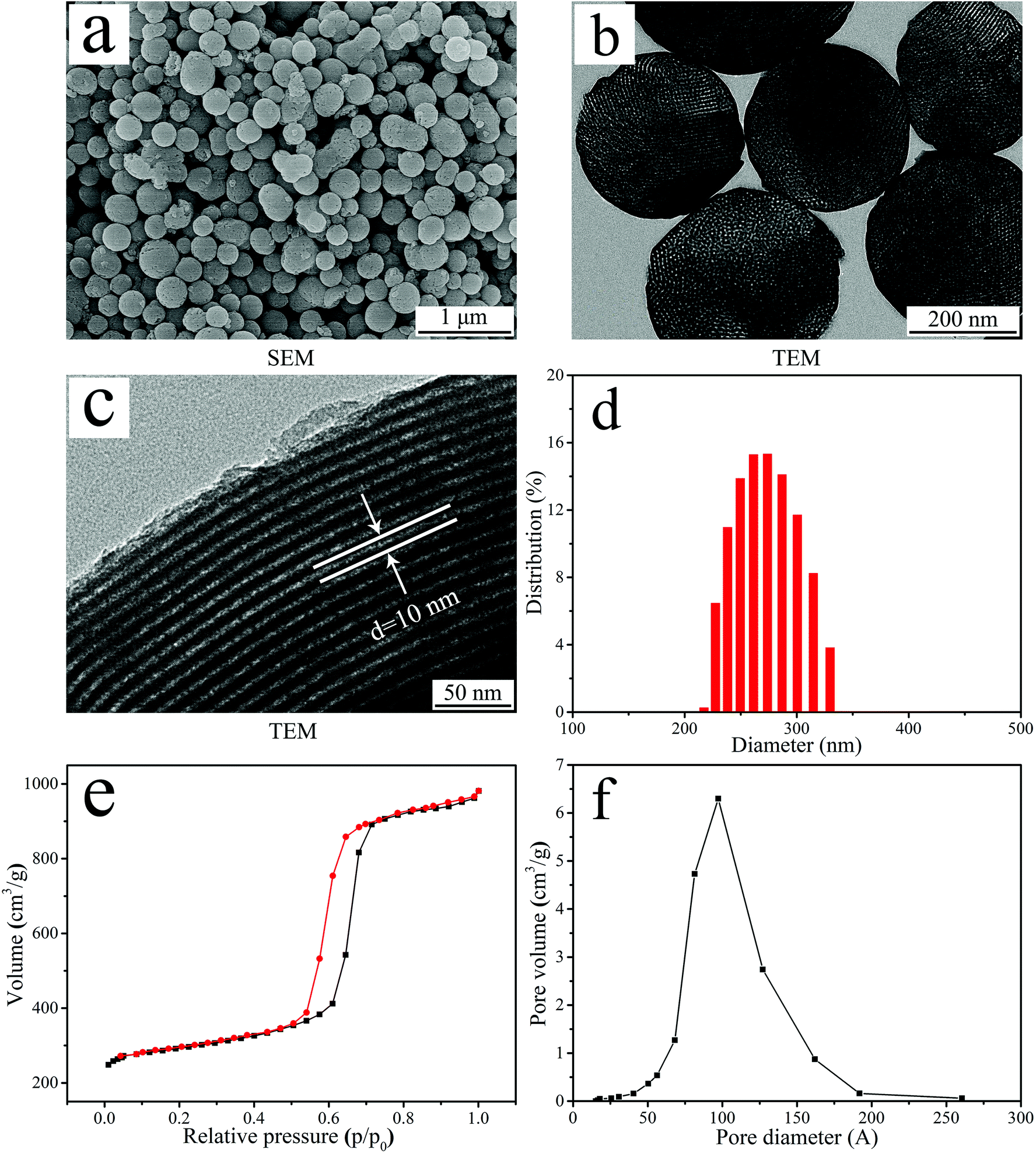 | ||
| Fig. 1 SEM image (a), TEM image (b and c), DLS analysis (d), N2 adsorption–desorption isotherm (e) and pore diameter distribution (f) of NTP. | ||
Fig. 1d showed the DLS analysis of particle size distribution of NTP. The particle size distribution of NTP ranged from 220 nm to 320 nm, and most of the particles were about 270 nm. Fig. 1e revealed the type IV isotherm pattern of N2 adsorption–desorption of NTP and the BET analysis indicated that the specific surface area of NTP was 313 m2 g−1. Fig. 1f revealed the pore size distribution of NTP, and the BJH analysis indicated that the nanopore volume and average nanopore size of NTP were 0.48 cm3 g−1 and 9.69 nm, respectively.
3.2 Characterization of PEEK, PN, SPK, and SPN
Fig. 2a shows the FTIR spectrum of NTP, PEEK, PN, SPK, and SPN. For PEEK, two peaks (at 1597 cm−1 and 1501 cm−1) were attributed to the R–O–R benzene in-plane vibration, while the peak at 1652 cm−1 represented the C![[double bond, length as m-dash]](https://www.rsc.org/images/entities/char_e001.gif) O carbonyl stretching vibration. In addition, the peak of R–O–R asymmetric stretching vibration was seen at 1226 cm−1, while the peak of R–CO–R benzene in-plane vibration was observed at 1308 cm−1. For NTP, the peak at 2335 cm−1 represented the Ta–O stretching vibration, while the peak at 930 cm−1 was attributed to the Ta–O–Ta stretching vibration.30 After sulfonation, the peak at 3399 cm−1 was found for both SPK and SPN, which represented the O–H stretching vibration of the sulfonic acid (SO3H) group, while other characteristic groups were found to contain OSO asymmetric stretching at 1255 cm−1 and SO symmetric stretching at 1024 cm−1.31
O carbonyl stretching vibration. In addition, the peak of R–O–R asymmetric stretching vibration was seen at 1226 cm−1, while the peak of R–CO–R benzene in-plane vibration was observed at 1308 cm−1. For NTP, the peak at 2335 cm−1 represented the Ta–O stretching vibration, while the peak at 930 cm−1 was attributed to the Ta–O–Ta stretching vibration.30 After sulfonation, the peak at 3399 cm−1 was found for both SPK and SPN, which represented the O–H stretching vibration of the sulfonic acid (SO3H) group, while other characteristic groups were found to contain OSO asymmetric stretching at 1255 cm−1 and SO symmetric stretching at 1024 cm−1.31
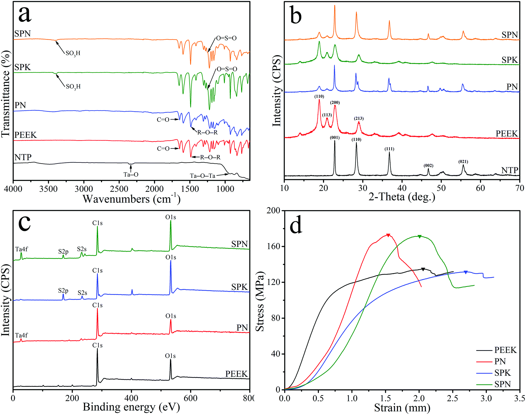 | ||
| Fig. 2 FTIR spectrum (a) and XRD spectrum (b) of NTP, PEEK, PN, SPK and SPN, and XPS spectrum (c) and stress–strain curve (d) of PEEK, PN, SPK and SPN. | ||
Fig. 2b shows the XRD spectrum of NTP, PEEK, PN, SPK, and SPN. The characteristic peaks of PEEK were seen at 2θ = 18.7°, 20.8°, 22.8°, and 28.8°. In addition, the characteristic peaks of NTP were found at 2θ = 23.1°, 28.6°, 37.0°, 46.9°, 50.5°, and 55.7°.32 The characteristic peaks of PEEK and NTP were found in both PN and SPN. Fig. 2c shows the XPS spectrum of PEEK, PN, SPK, and SPN. C 1s and O 1s peaks were observed in all the groups, while Ta 4f peaks were found in both PN and SPN. Moreover, S 2p and S 2s peaks appeared in both SPK and SPN. Fig. 2d shows the stress–strain curve of PEEK, PN, SPK, and SPN, and the peak of stress–strain curve represents the compressive strengths of the samples. The compressive strength of PEEK, PN, SPK, and SPN was 134.87 ± 0.82 MPa, 172.91 ± 1.66 MPa, 131.63 ± 1.54 MPa, and 171.49 ± 2.25 MPa, respectively.
Fig. 3 shows the SEM images and EDS spectrum of PEEK, PN, SPK, and SPN. PEEK exhibits a smooth surface at both low and high magnifications, while PN shows a rough surface with many NTP particles. After sulfonation, many micropores (pore size of about 1–3 μm) were seen on the surface of both SPK and SPN, and many NTP particles were seen in the microporous structure of SPN. From the EDS spectrum, C and O elements existed in all the groups, while the Ta element appeared in both PN and SPN, and the S element was found in both SPK and SPN.
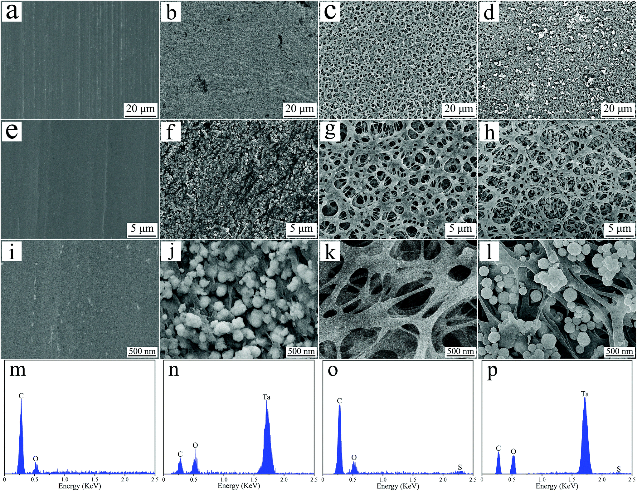 | ||
| Fig. 3 SEM images of PEEK (a, e and i), PN (b, f and j), SPK (c, g and k) and SPN (d, h and l), and EDS spectrum of PEEK (m), PN (m), SPK (o) and SPN (p). | ||
Fig. 4a shows the 3D laser confocal image of PEEK, PN, SPK, and SPN. The surface of PN was rougher than that of PEEK. In addition, both SPK and SPN showed a microporous surface. The micro roughness (Table 2) of PEEK, PN, SPK, and SPN was 1.76 ± 0.02 μm, 2.35 ± 0.77 μm, 6.96 ± 0.22 μm, and 7.48 ± 0.15 μm, respectively.
 | ||
| Fig. 4 3D laser confocal images (a), 3D AFM images (b), water and diiodomethane contact angle (c) and surface energy (d) of PEEK, PN, SPK and SPN. Error bars represent mean ± standard deviation with n = 5 (* p < 0.05, ** p < 0.01, *** p < 0.001). | ||
| Group | Micro roughness (μm) | Nano roughness (nm) |
|---|---|---|
| PEEK | 1.76 ± 0.02 | 10.01 ± 0.85 |
| PN | 2.35 ± 0.07 | 12.64 ± 1.77 |
| SPK | 6.96 ± 0.22 | 28.55 ± 2.09 |
| SPN | 7.48 ± 0.15 | 29.81 ± 1.50 |
Fig. 4b shows the 3D AFM images of PEEK, PN, SPK, and SPN. Compared with PEEK, the surfaces of both PN and SPK show many nanostructured peaks, while the surface of SPN exhibits more nanostructured pits. The nano roughness (Table 2) of PEEK, PN, SPK, and SPN was 10.01 ± 0.85 μm, 12.64 ± 1.77 μm, 28.55 ± 2.09 μm, and 29.81 ± 1.50 μm, respectively.
The water contact angle was measured and is shown in Fig. 4c. In addition, the diiodomethane contact angle was measured, and the surface energy was calculated and is shown in Fig. 4d. Compared with PEEK, the hydrophilicity as well as the surface energy of PN and SPN were improved. Moreover, SPN showed the highest hydrophilicity as well as surface energy compared with PN and SPK.
3.3 Drug loading onto the samples
Fig. 5a shows the FTIR spectrum of GT, SPKG, and SPNG. For GT, the peak at 3414 cm−1 represents the phenolic O–H stretching vibration, while the peak at 1650 cm−1 is attributed to the CO stretching vibration. Moreover, the peak at 1614 cm−1 and 1308 cm−1 belong to the CC and C–O–C stretching vibration, respectively. The characteristic peaks of GT were found in both SPKG and SPNG, while the intensity of GT characteristic peaks in SPNG was higher than that in SPKG. Fig. 5b shows the XRD spectrum of GT, SPKG, and SPNG. For GT, the characteristic peaks were observed at 2θ = 12.6°, 14.9°, 18.0°, 22.5°, 26.3°, 28.7°, 36.3°, and 40.0°. The characteristic peaks of GT appeared in both SPKG and SPNG, while the peak intensity of GT in SPNG is higher than that in SPKG.
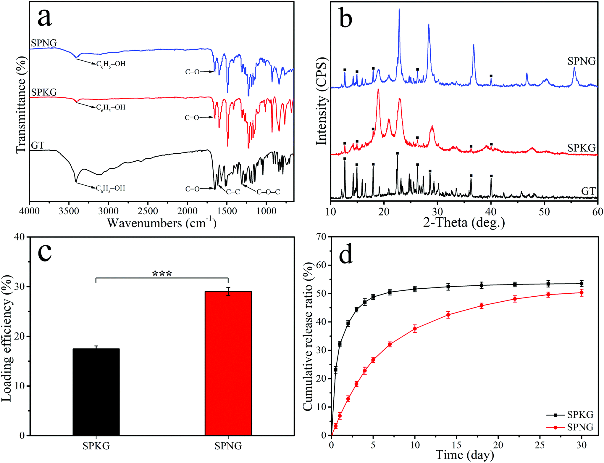 | ||
| Fig. 5 FTIR spectrum (a) and XRD spectrum (b) of GT, SPKG and SPNG, and GT loading efficiency (c) and GT cumulative release ratio (d) of SPKG and SPNG (■ represents characteristic peaks of GT). Error bars represent mean ± standard deviation with n = 5 (* p < 0.05, ** p < 0.01, *** p < 0.001). | ||
Fig. 5c shows the loading efficiency of GT onto the surface of SPKG and SPNG after soaking for 24 hours. The loading efficiency of GT onto SPKG was 27.46 ± 0.50% while the loading efficiency of GT onto SPNG was 42.01 ± 0.82%. Fig. 5d shows the GT cumulative release ratio for SPKG and SPNG. SPKG showed a sudden GT release behavior in the first 5 days and the GT release ratio of SPKG was about 48.80 ± 0.91%. However, SPNG showed sustained GT release behavior in the whole GT release experiment. After 30 days, the GT cumulative release ratio of SPKG was 53.50 ± 1.08%, while that of SPNG was about 50.30 ± 1.25%.
3.4 Antibacterial activity in vitro
Fig. 6 shows the antibacterial activity of PEEK, PN, SPK, SPN, and SPNG for E. coli and S. aureus. From the colony distribution image (Fig. 6a), a large number of colonies were observed for PEEK and PN. However, few colonies were found for SPK and no colonies were found for SPNG.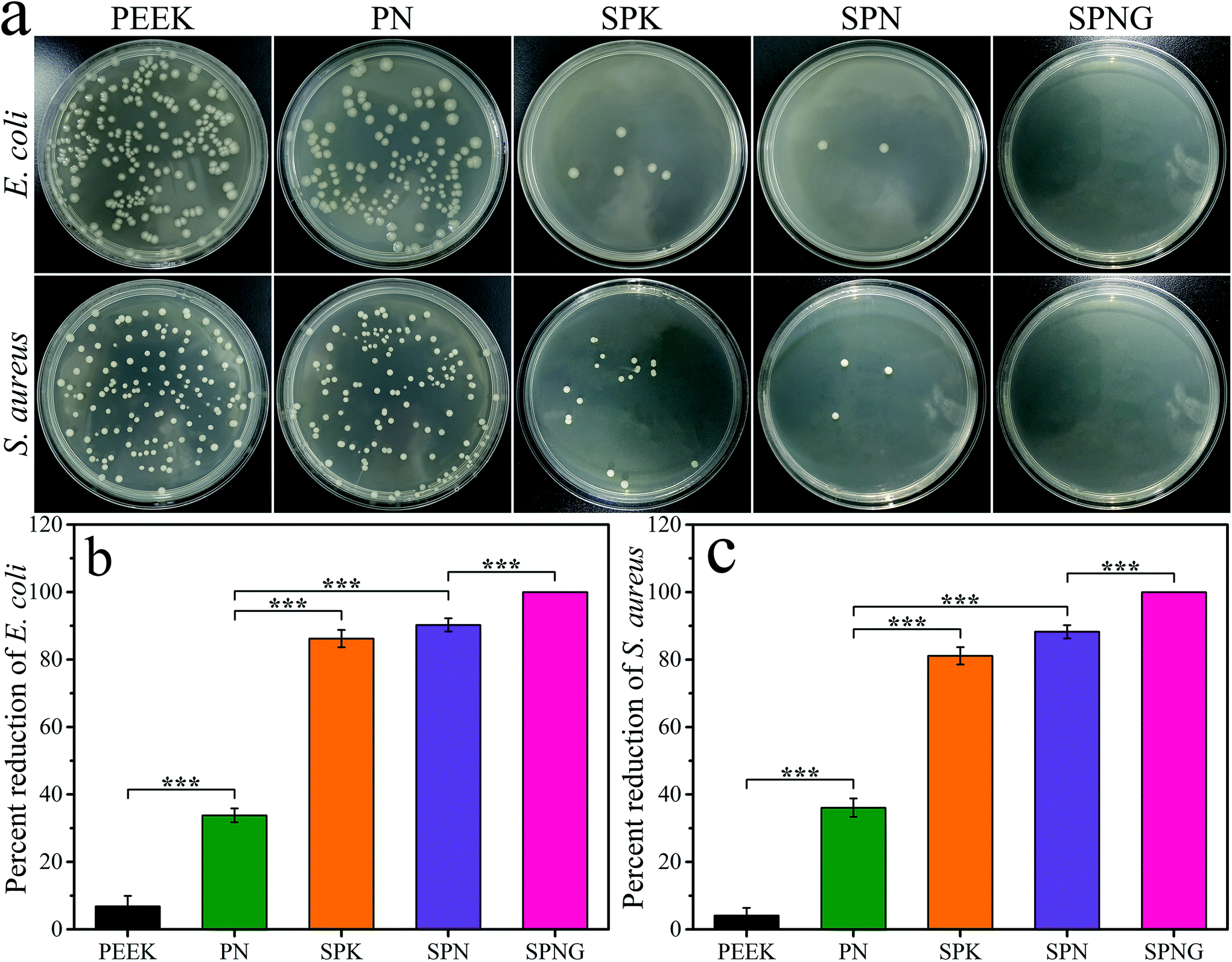 | ||
| Fig. 6 Colony distribution images (a), and percent reduction of E. coli (b) and S. aureus (c) for PEEK, PN, SPK, SPN and SPNG at 24 hours after culturing. Error bars represent mean ± standard deviation with n = 5 (* p < 0.05, ** p < 0.01, *** p < 0.001). | ||
From the percent reduction of E. coli (Fig. 6b) and S. aureus (Fig. 6c), the antibacterial ratio of PEEK, PN, SPK, SPN, and SPNG for E. coli was 6.84 ± 3.11%, 33.82 ± 2.04%, 86.20 ± 2.56%, 90.27 ± 1.96%, and 100%, respectively, while the antibacterial ratio for S. aureus was 4.10 ± 2.28%, 36.08 ± 2.74%, 81.12 ± 2.56%, 88.27 ± 1.96%, and 100%, respectively.
3.5 Cell experiments in vitro
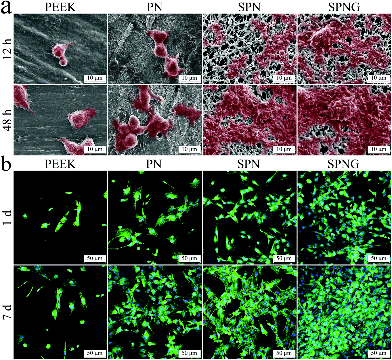 | ||
| Fig. 7 SEM images (a) of morphology of BMSC on PEEK, PN, SPN and SPNG at 12 and 48 hours after culturing, and CLSM images (b) of cytoskeletons stained by DAPI and FITC of the cells on PEEK, PN, SPN and SPNG at 1 and 7 days after culturing. | ||
Fig. 7b shows the CLSM images of the cytoskeletons of BMSC on PEEK, PN, SPN, and SPNG at day 1 and 7 after culturing. The cell nucleus for each cell was stained in blue while the cytoplasm for each cell in all the cases were stained in green. At both day 1 and 7, the density of cells for SPN was higher than that of PN, with more cells on SPN. In addition, the density of cells for SPNG was higher than that of SPN, with the most cells found on SPNG. With the increase in the cultivation time, the density of cells on PN, SPN, and SPNG was improved. However, several cells with spherical shape were observed on the PEEK surface at both day 1 and 7.
Fig. 8a shows the OD values of BMSC on PEEK, PN, SPN, and SPNG at different times after culturing. At day 1, the OD values of the cells on SPN and SPNG were higher than that of PN, and the value for PN was higher than that of PEEK. At day 3 and day 7, the OD value for SPNG was higher than that of SPN, and the value for SPN was higher than that for PN and PEEK. The OD values for PN, SPN, and SPNG increased with time while there was slight increase for PEEK.
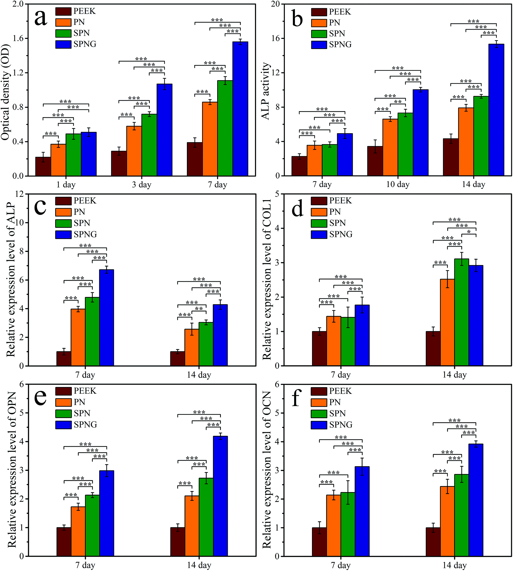 | ||
| Fig. 8 OD values (a) of BMSC on PEEK, PN, SPN and SPNG at 1, 3 and 7 days after culturing; ALP activity (b) of the cells on PEEK, PN, SPN and SPNG at 7, 10 and 14 days after culturing; osteogenic gene expression (c: ALP, d: COL1, e: OPN, f: OCN) of the cells on PEEK, PN, SPN and SPNG at 7 and 14 days after culturing. Error bars represent mean ± standard deviation with n = 5 (* p < 0.05, ** p < 0.01, *** p < 0.001). | ||
Fig. 8b shows the ALP activity of BMSC on PEEK, PN, SPN, and SPNG at different times after culturing. At day 7, the ALP activity of SPNG showed no obvious difference from SPN, PN, and PEEK. At day 10 and day 14, the ALP activity of SPNG was higher than that of both SPN and PN, which were significantly higher than that of PEEK.
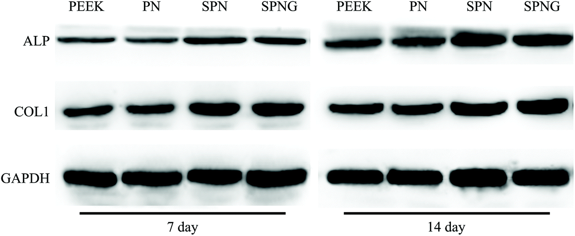 | ||
| Fig. 9 Western blot image of the osteogenic protein expression (ALP, COL1) of BMSC cultivated on PEEK, PN, SPN and SPNG at 7 and 14 days. | ||
3.6 Animal experiments in vivo
Fig. 10a shows the surgical procedure of the in vivo animal experiment and Fig. 10b showed the femur photos of PEEK, PN, SPN, and SPNG at 4 and 12 weeks after implantation. All the samples showed different levels of NB formation, which was located in the right femoral condyle of the rabbits. At 4 and 12 weeks, the amount of NB for SPNG was higher than that of SPN, and that of SPN was higher than those of PN and PEEK. In addition, the amount of NB for PN, SPN, and SPNG at 12 weeks was higher than that at 4 weeks.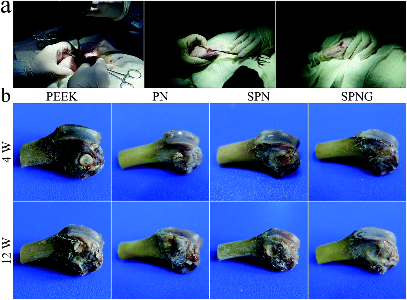 | ||
| Fig. 10 Surgery procedure of in vivo animal experiment (a), and femur photo (b) of PEEK, PN, SPN and SPNG at 4 and 12 weeks after implantation. | ||
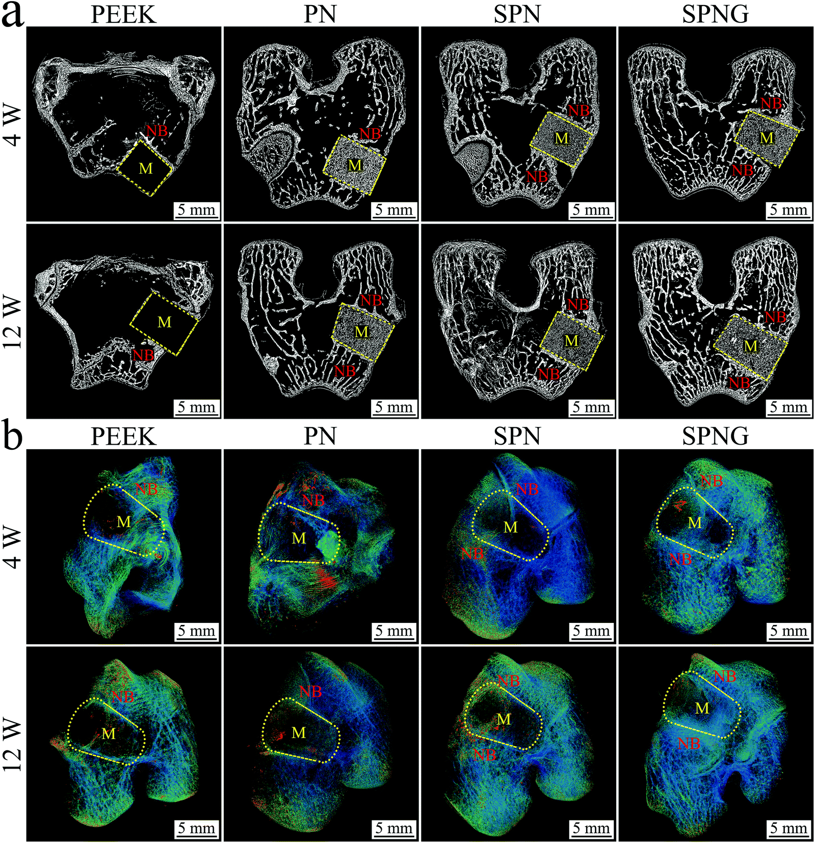 | ||
| Fig. 11 2D (a) and 3D (b) reconstructed image from SRμCT of PEEK, PN, SPN and SPNG at 4 and 12 weeks after implantation (M: material; NB: new bone). | ||
Fig. 12 shows the quantitative analysis of new bone formation (BMD, BV/TV, Tb·N, and Tb·Th) from SRμCT of PEEK, PN, SPN, and SPNG at 4 and 12 weeks after implantation. At 4 weeks, BMD, BV/TV, Tb·N, and Tb·Th for SPNG were higher than SPN, and those for SPN were higher than those of PN and PEEK. At 12 weeks, the BMD and BV/TV for SPNG were higher than those of SPN and PN while there were no obvious differences between SPN and PN. In addition, the Tb·N and Tb·Th for SPNG were higher than those of SPN and PN, and those of SPN were higher than those of PN. The BMD, BV/TV, Tb·N, and Tb·Th for PEEK were the lowest at both 4 and 12 weeks.
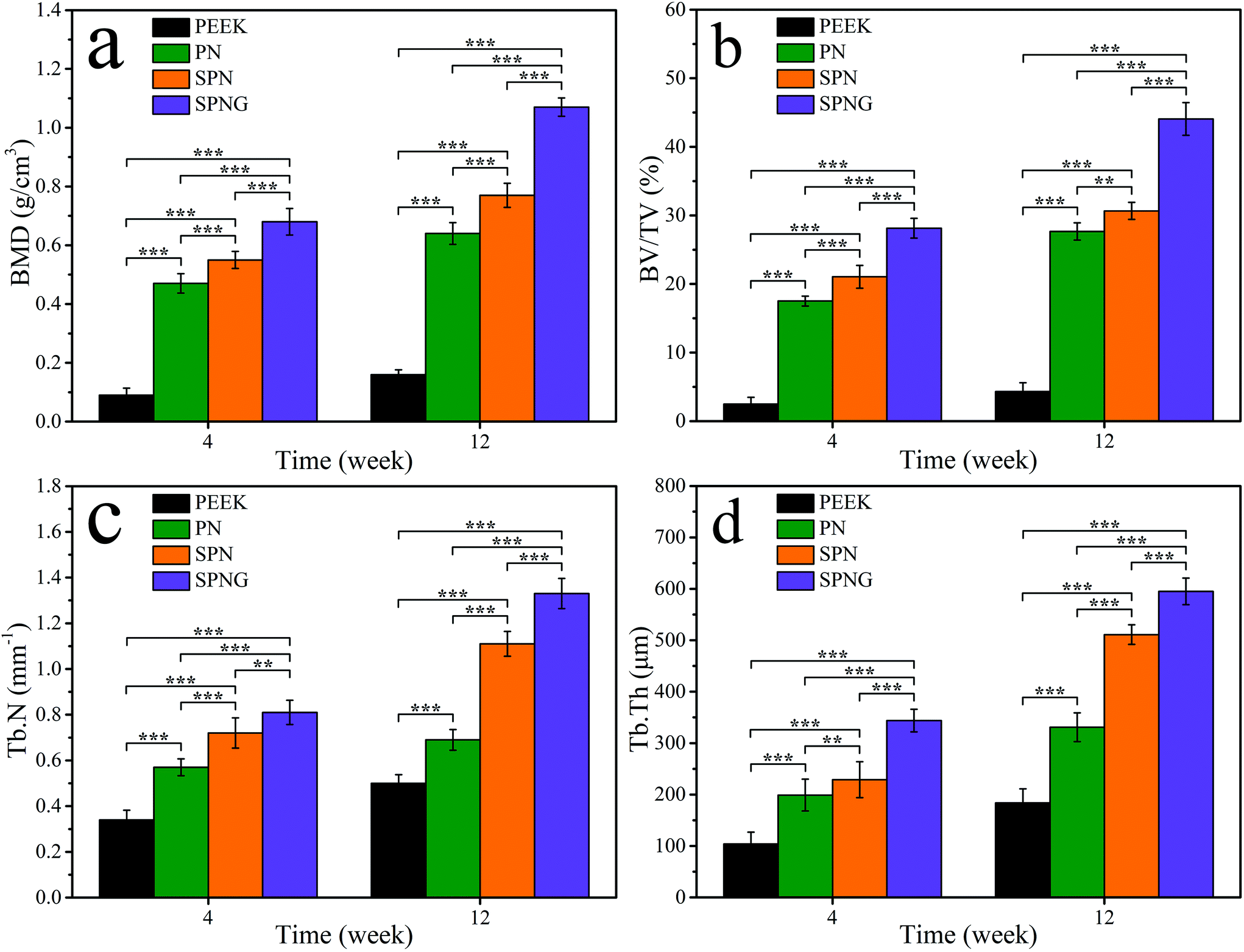 | ||
| Fig. 12 Quantitative analysis of BMD (a), BV/TV (b), Tb·N (c) and Tb·Th (d) of PEEK, PN, SPN and SPNG at 4 and 12 weeks after implantation. Error bars represent mean ± standard deviation with n = 5 (* p < 0.05, ** p < 0.01, *** p < 0.001). | ||
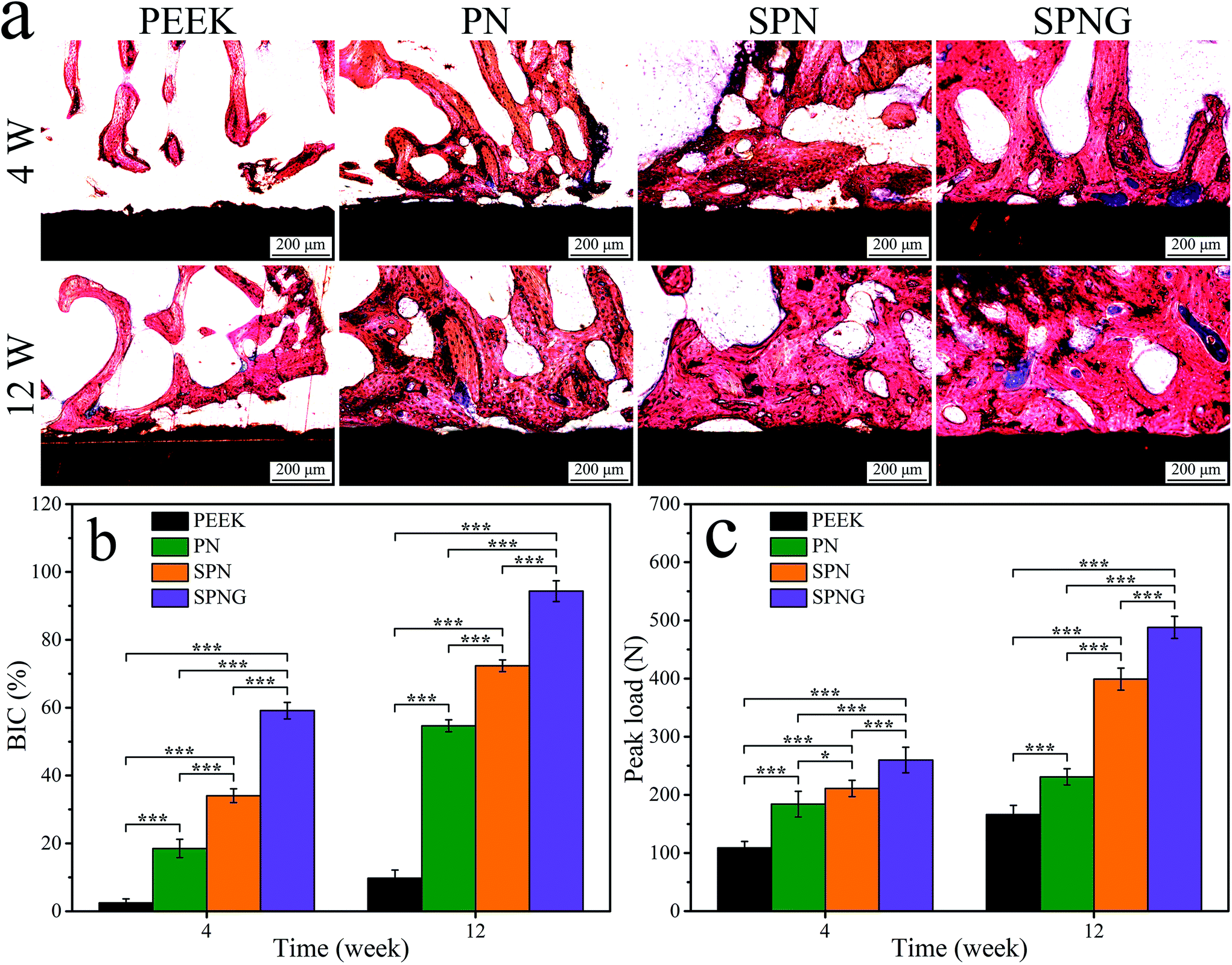 | ||
| Fig. 13 Histological sections images (a), quantitative analysis of BIC (b) and push-out load (c) of PEEK, PN, SPN and SPNG at 4 and 12 weeks after implantation. Error bars represent mean ± standard deviation with n = 5 (* p < 0.05, ** p < 0.01, *** p < 0.001). | ||
Fig. 13b reveals the quantitative analysis of bone-implant contact (BIC). At 4 weeks, the BIC of SPNG, SPN, PN, and PEEK was 59.14%, 34.05%, 18.51%, and 2.46%, respectively. At 12 weeks, the BIC of SPNG, SPN, PN, and PEEK was 94.34%, 72.34%, 54.66%, and 9.73%, respectively.
4. Discussion
PEEK has become the leading implantable materials and has been widely applied as an implant for replacing bone tissues in the human body.6 Rapid bone formation and osteointegration are essential for the initial and long-term stability of implants; PEEK is bioinert, which hardly stimulates cell responses, and promotes bone formation and osteointegration.3,6 Therefore, in the present study, to improve the bioactivity of PEEK and thus to promote bone formation and osteointegration, a strategy employing the combination of PEEK composite/surface modification with the drug-loaded method was proposed. Firstly, tantalum pentoxide (NTP) submicron particles (sizes of around 300 nm) with nanopores (pore size of about 10 nm) were synthesized and then blended with PEEK to fabricate the PEEK/NTP composite (PN). Subsequently, PN was treated with concentrated H2SO4. After surface modification, many micropores (pore size of about 2 μm) were made on the sulfonated PN (SPN) surface with more NTP particles exposed on the walls of the micropores compared with PN. The microporous walls of SPN-containing NTP with nanopores formed a hierarchical micro & nanoporous surface. In addition, after the sulfonation of PN, the SO3H group was grafted on SPN because of the hydrogen on the benzene ring in the PEEK molecular chain substituted by SO3H.33Studies have demonstrated that the surface features (surface roughness, hydrophilicity, and surface energy) of implantable materials could effectively regulate and control their biological performances.23,25,34 In this study, compared with PEEK, the micro and nano roughness of PN were slightly increased due to the presence of some NTP submicron particles on its surface. Furthermore, compared with PN, the micro and nano roughness of SPN were significantly increased due to the presence of the micro & nanoporous surface. Moreover, in comparison with PEEK, the hydrophilicity and surface energy of PN (some NTP on its surface) increased because NTP is an inorganic material with high hydrophilicity as well as the surface energy. In addition, compared with PN, SPN exhibited high hydrophilicity as well as the surface energy due to the combination of more NTP particles exposed on the microporous surface and the presence of SO3H groups (hydrophilic group).34 The rough and hydrophilic surface with high surface energy of implantable materials could increase the adsorption of more anchoring proteins (e.g., vinculin and fibronectin), which caused a favorable micro-environment for osteoblast responses.35
Genistein (GT) is a natural molecule that possesses antibacterial activity as it interferes with nucleic acid synthesis, cytoplasmic membranes, and energy metabolisms of E. coli and S. aureus.36 In this study, GT was loaded into the hierarchical micro & nanoporous surface of SPN to create a drug-loaded implant of SPNG. The loading efficiency of GT on SPNG was obviously higher than that of SPKG. Obviously, compared to SPKG with only the microporous surface, the micro & nanoporous surface of SPNG-containing NTP with nanopores might possess high specific surface area and pore volume, thereby improving the loading efficiency of GT. For the release of GT from the samples, SPKG showed a sudden release behavior while SPNG showed sustained release behavior. NTP with Ta–OH groups could form hydrogen bonding with abundant hydroxyl (–OH) groups in the GT molecule, which might enhance the loading efficiency and sustained release of GT.28 Therefore, it could be suggested that the micro & nanoporous surface and Ta–OH groups on SPNG might cause the sustained release of GT compared with SPKG.
Due to zero bioactivity, PEEK shows no osseointegration, which improves the possibility of bacteria entering the biological environment that potentially induces infections.6,37 In the present study, PEEK showed no antibacterial activity for E. coli and S. aureus while PN with NTP exhibited very low antibacterial activity because Ta ions (positive charge) in NTP react with the bacterial membrane (negative charge) through electrostatic attraction and initiate cell wall leakage, leading to the death of bacteria.38 Compared with PEEK and PN, SPN exhibited better antibacterial activity because of the presence of SO3H groups. SO3H groups with a negative charge generated electrostatic repulsion with the bacterial membrane (negative charge), thereby hindering the adhesion of bacteria.39 Moreover, compared with SPN, SPNG exhibited the highest antibacterial activity because of the synergistic effects of both SO3H and GT with antibacterial activity.
The interactions of cells/tissues with the implants predominantly depend on their surface characteristics, with rough and hydrophilic as well as porous surfaces improving the cell adhesion, proliferation, and differentiation as well as the formation of extracellular matrices.40 In this study, compared with PN, the adhesion of BMSC on both SPN and SPNG increased, while no obvious difference between SPN and SPNG was found. Clearly, the micro & nanoporous surface of SPN and SPNG significantly promoted cell adhesion while the sustained release of GT from SPNG showed no obvious effect on cell adhesion. The favorable initial cell adhesion on the biomaterial surface has great potential for promoting cell spreading, migration, proliferation, as well as differentiation.41 Moreover, the proliferation the BMSC on SPN was higher than that on PN, and the proliferation on SPNG was higher than that on SPN. It can be suggested that the micro & nanoporous surface on SPN promoted cell proliferation and the sustained release of GT from SPNG further accelerated cell proliferation.
To obtain optimal new bone formation around the implants, the improvement of cell functions related to osteoblastic differentiation is also required.42,43 ALP enzyme is an osteogenic marker that frequently exhibits high expression in osteoblasts, which is related to the early stage of mineralization of new bones.43 In this study, the ALP activity of BMSC on SPN was higher than that of PN, and the activity of SPNG was higher than that for SPN. Obviously, the micro & nanoporous surface on SPN promoted the ALP activity, and the sustained release of GT from SPNG further enhanced the ALP activity. In addition, the osteogenic differentiation of BMSC was determined by testing the expressions of osteogenesis-related genes/proteins of cells on the samples. For the osteogenesis gene expressions, at the early stage (day 7), compared with PN, SPN promoted the expression of ALP and OPN, and SPNG further enhanced the expressions of ALP, COL1, OPN, and OCN. At the later stage (day 14), compared with PN, SPN improved the expressions of COL1, OPN, and OCN, and SPNG further enhanced the expressions of OPN and OCN. For the osteogenic proteins expressions, at the early stage (day 7), compared with PN, both SPN and SPNG improved the expressions of ALP and COL1. At the later stage (day 14), SPNG enhanced the expressions of ALP and COL1 compared with those of SPN and PN. It could be suggested that the micro & nanoporous surface on SPN improved the osteogenic differentiation of BMSC, and the sustained release of GT from SPNG further enhanced the osteoblastic differentiation.
The surface chemical composition, micro & nano structure, roughness, hydrophilicity, surface energy, etc., have been confirmed to have positive effects on the cellular behaviors and functions, as well as osteogenesis and osteointegration.43,44 In the present study, at different times after implantation, the osteogenesis of the implanted samples was evaluated by SRμCT including 2D/3D reconstructed images and quantitative analysis of new bone formation (BMD, BV/TV, Tb·N, and Tb·Th). At both 4 and 12 weeks, the amount of new bone (NB) formation around SPN were improved compared with that of PN, and the amount of NB for SPNG further increased compared with that of SPN. In addition, osteointegration was evaluated by testing the push-out loads of the implants after implantation in vivo for different times. At 4 and 12 weeks, the push-out loads for SPN obviously increased compared with those of PN and the push-out load for SPNG further increased compared with those of SPN. The results confirmed that SPNG improved the NB formation and the push-out loads, revealing good osteointegration compared with SPN and PN.
In addition, the images of histological sections and quantitative analysis of BIC were also utilized to evaluate the osteogenesis and osteointegration of implants. At 4 and 12 weeks, the amount of NB formation around SPN obviously increased compared with PN and the amount of NB formation for SPNG further increased compared with SPN. Moreover, there were obvious gaps at the interfaces between NB and the implants (PN and PEEK), while the NB tissues were found to be directly combined with the surface of the implants (SPNG and SPN) without gaps, indicating good osteointegration. For BIC, compared with PN (54.66%) and SPN (72.34%), SPNG (94.34%) exhibited the highest result. The results confirmed that SPNG improved the NB formation and BIC, revealing good osteointegration compared with SPN and PN. It could be suggested that SPN with hierarchical micro & nanoporous surface promoted bone formation and osteointegration, and the sustained release of GT from SPNG further accelerated bone formation and osteointegration.
Surface features such as chemical composition, roughness, hydrophilicity, surface energy, and functional groups significantly influence the cell behaviors as well as the bone formation and osseointegration of the implants.45 In this study, compared with PN and PEEK, SPN with hierarchical micro & nanoporous surface containing NTP with nanopores obviously induced cell adherence, growth, proliferation, and differentiation, and promoted bone formation and osteointegration because of high surface roughness, hydrophilicity, and surface energy. Moreover, compared with SPN, SPNG further stimulated cell responses, and accelerated osteointegration due to the sustained release of GT. Therefore, the GT-loaded SPNG was superior to SPN with identical hierarchical micro & nanoporous surface and SO3H groups. The in vitro & in vivo investigations confirmed that the surface micro-nanostructure and SO3H groups as well as the GT loaded on the SPNG could not only stimulate the responses of BMSC but also accelerate osteogenesis and osteointegration. In short, the improvement of BMSC responses in vitro as well as the promotion of osteointegration in vivo using SPNG was due to the synergistic effects of hierarchical micro & nanoporous surface containing microparticles of NTP with nanopores and functional groups of SO3H as well as the sustained release of GT. The GT-loaded SPNG with biocompatibility and antibacterial activity accelerated the osteointegration, which could be a promising candidate for drug-loaded implants in implantable spinal as well as orthopedic applications.
5. Conclusions
Submicron particles of NTP with nanopores were synthesized and blended with PEEK to fabricate PN. By sulfonation treatment, hierarchical micro & nanoporous structures containing NTP and SO3H groups were created on the SPN surface. Compared with PN, SPN with a micro & nanoporous surface containing NTP and SO3H groups exhibited higher roughness, hydrophilicity, and surface energy. In addition, SPN with micro & nanoporous surface was utilized to construct GT-loaded SPN (SPNG), which showed high GT loading capacity as well as sustained release of GT. Furthermore, SPNG possessing excellent antibacterial activity inhibited the growth of E. coli and S. aureus in vitro because of the synergistic effects of both SO3H groups and the sustained release of GT. Moreover, compared with PN, SPN significantly stimulated the BMSC responses (adhesion and proliferation as well as osteogenic differentiation) in vitro and enhanced bone formation and osteointegration in vivo. In addition, compared with SPN, SPNG further stimulated the BMSC responses and enhanced the osteointegration. In brief, SPNG with a micro & nanoporous surface containing NTP and SO3H groups as well as the sustained release of GT possessed excellent antibacterial activity, and accelerated osteogenesis and osteointegration, which might have tremendous potential as drug-loaded implants for bone substitutes.Conflicts of interest
There are no conflicts to declare.Acknowledgements
The grants were from the Shanghai Science and Technology Development Foundation (17441900600 and 19441906100), the National Natural Science Foundation of China (81771990 and 81801845), and Shenzhen Fundamental Research Program (JCYJ20190807160811355).References
- H. Mahjoubi, E. Buck, P. Manimunda, R. Farivar, R. Chromik, M. Murshed and M. Cerruti, Acta Biomater., 2017, 47, 149–158 CrossRef CAS.
- J. Khoury, I. Selezneva, S. Pestov, V. Tarassov, A. Ermakov, A. Mikheev, M. Lazov, S. R. Kirkpatrick, D. Shashkov and A. Smolkov, Bioact. Mater., 2019, 4, 132–141 CrossRef.
- Y. Y. Zheng, C. D. Xiong, S. L. Zhang, X. Y. Li and L. F. Zhang, Mater. Sci. Eng., C., 2015, 55, 512–523 CrossRef CAS.
- M. L. Chen, L. P. Ouyang, T. Lu, H. Y. Wang, F. H. Meng, Y. Yang, C. Q. Ning, J. Z. Ma and X. Y. Liu, ACS Appl. Mater. Interfaces, 2017, 9, 16825–16834 Search PubMed.
- S. Bierbaum, S. Mulansky, E. Bognar, I. Kientzl, P. Nagy, N. E. Vrana, M. Weszl, E. Boschke, D. Scharnweber and C. Wolf-Brandstetter, Biomater. Sci., 2018, 6, 1390–1402 RSC.
- X. Xu, Y. L. Li, L. X. Wang, Y. Li, J. J. Pan, X. M. Fu, Z. Y. Luo, Y. Sui, S. Q. Zhang, L. Wang, Y. F. Ni, L. Zhang and S. C. Wei, Biomaterials, 2019, 212, 98–114 CrossRef CAS.
- A. Gao, Q. Liao, L. X. Xie, G. M. Wang, W. Zhang, Y. Z. Wu, P. H. Li, M. Guan, H. B. Pan, L. P. Tong, P. K. Chu and H. Y. Wang, Biomaterials, 2020, 230, 119642 CrossRef CAS.
- J. L. Yan, W. H. Zhou, Z. J. Jia, P. Xiong, Y. Y. Li, P. Wang, Q. Y. Li, Y. Cheng and Y. F. Zheng, Acta Biomater., 2018, 79, 216–229 CrossRef CAS.
- P. Sikder, C. R. Grice, B. R. Lin, V. K. Goel and S. B. Bhaduri, ACS Biomater. Sci. Eng., 2018, 4, 2767–2783 CrossRef CAS.
- F. B. Torstrick, A. S. P. Lin, D. Potter, D. L. Safranski, T. A. Sulchek, K. Gall and R. E. Guldberg, Biomaterials, 2018, 185, 106–116 CrossRef CAS.
- M. A. U. Rehman, S. Ferraris, W. H. Goldmann, S. Perero, F. E. Bastan, Q. Nawaz, G. G. di Confiengo, M. Ferraris and A. R. Boccaccini, ACS Appl. Mater. Interfaces, 2017, 9, 32489–32497 CrossRef.
- Y. Ding, Y. S. Hao, Z. Yuan, B. L. Tao, M. W. Chen, C. C. Lin, P. Liu and K. Y. Cai, Biomater. Sci., 2020, 8, 1840–1854 RSC.
- S. Bakhshandeh and S. A. Yavari, J. Mater. Chem. B, 2018, 6, 1128–1148 RSC.
- J. Raphel, M. Holodniy, S. B. Goodman and S. C. Heilshorn, Biomaterials, 2016, 84, 301–314 CrossRef CAS.
- C. R. Arciola, D. Campoccia and L. Montanaro, Nat. Rev. Microbiol., 2018, 16, 397–409 CrossRef CAS.
- C. Park, S. W. Lee, J. Kim, E. H. Song, H. D. Jung, J. U. Park, H. E. Kim, S. Kim and T. S. Jang, Biomater. Sci., 2019, 7, 2907–2919 RSC.
- T. Lu, J. Wen, S. Qian, H. L. Cao, C. Q. Ning, X. X. Pan, X. Q. Jiang, X. Y. Liu and P. K. Chu, Biomaterials, 2015, 51, 173–183 CrossRef CAS.
- M. Sarraf, B. A. Razak, B. Nasiri-Tabrizi, A. Dabbagh, N. H. Abu Kasim, W. J. Basirun and E. Bin Sulaiman, J. Mech. Behav. Biomed. Mater., 2017, 66, 159–171 CrossRef CAS.
- N. Horandghadim, J. Khalil-Allafi and M. Urgen, Mater. Sci. Eng., C, 2019, 102, 683–695 CrossRef CAS.
- J. Xu, W. Hu, S. Xu, P. Munroe and Z. H. Xie, ACS Biomater. Sci. Eng., 2016, 2, 73–89 CrossRef CAS.
- N. Horandghadim, J. Khalil-Allafi, E. Kacar and M. Urgen, J. Alloys Compd., 2019, 799, 193–204 CrossRef CAS.
- J. Xu, X. K. Bao, T. Fu, Y. H. Lyu, P. Munroe and Z. H. Xie, Ceram. Int., 2018, 44, 4660–4675 CrossRef CAS.
- D. Xu, Y. X. Wan, Z. H. Li, C. B. Wang, Q. X. Zou, C. Du and Y. J. Wang, Biomater. Sci., 2020, 8, 3286–3300 RSC.
- Y. Zhu, K. Zhang, R. Zhao, X. J. Ye, X. N. Chen, Z. W. Xiao, X. Yang, X. D. Zhu, K. Zhang, Y. J. Fan and X. D. Zhang, Biomaterials, 2017, 147, 133–144 CrossRef CAS.
- C. C. Yin, Y. J. Zhang, Q. Cai, B. S. Li, H. Yang, H. L. Wang, H. Qi, Y. M. Zhou and W. Y. Meng, J. Biomed. Mater. Res., Part A, 2017, 105, 757–769 CrossRef CAS.
- C. H. Gao, G. Lin, Z. X. Lei, Q. Zheng, J. S. Lin and Z. A. Lin, J. Mater. Chem. B, 2017, 5, 7496–7503 RSC.
- Y. Y. Chen, G. S. Song, Z. L. Dong, X. Yi, Y. Chao, C. Liang, K. Yang, L. Cheng and Z. Liu, Small, 2017, 13, 1602869 CrossRef.
- S. Buddhiranon, L. A. DeFine, T. S. Alexander and T. Kyu, Polymer, 2016, 105, 104–112 CrossRef CAS.
- S. H. Lee, J. K. Kim and H. D. Jang, Int. J. Mol. Sci., 2014, 15, 10605–10621 CrossRef CAS.
- S. S. Arbuj, U. P. Mulik and D. P. Amalnerkar, Nanosci. Nanotechnol. Lett., 2013, 5, 968–973 CrossRef CAS.
- T. Y. Inan, H. Dogan, E. E. Unveren and E. Eker, Int. J. Hydrogen Energy, 2010, 35, 12038–12053 CrossRef CAS.
- S. Anandan, N. Pugazhenthiran, T. Selvamani, S. H. Hsieh, G. J. Lee and J. J. Wu, Catal. Sci. Technol., 2012, 2, 2502–2507 RSC.
- L. P. Ouyang, Y. C. Zhao, G. D. Jin, T. Lu, J. H. Li, Y. Q. Qiao, C. Q. Ning, X. L. Zhang, P. K. Chu and X. Y. Liu, Biomaterials, 2016, 83, 115–126 CrossRef CAS.
- B. B. Chang, J. Fu, Y. L. Tian and X. P. Dong, J. Phys. Chem. C, 2013, 117, 6252–6258 CrossRef CAS.
- M. F. Griffin, R. G. Palgrave, A. M. Seifalian, P. E. Butler and D. M. Kalaskar, Biomater. Sci., 2016, 4, 145–158 RSC.
- A. Aires, E. Marrinhas, R. Carvalho, C. Dias and M. J. Saavedra, BioMed Res. Int., 2016, 2016, 5201879 Search PubMed.
- W. Liu, J. H. Li, M. Q. Cheng, Q. J. Wang, Y. B. Qian, K. W. K. Yeung, P. K. Chu and X. L. Zhang, Biomaterials, 2019, 208, 8–20 CrossRef CAS.
- A. Meidanchi and A. Jafari, Opt. Laser Technol., 2019, 111, 89–94 CrossRef CAS.
- X. H. He, Y. Deng, Y. Yu, H. Lyu and L. Liao, Colloids Surf., B, 2019, 181, 767–777 CrossRef CAS.
- S. C. Neves, C. Mota, A. Longoni, C. C. Barrias, P. L. Granja and L. Moroni, Biofabrication, 2016, 8, 025012 CrossRef.
- X. D. Zhang, D. L. Zeng, N. Li, J. Wen, X. Q. Jiang, C. S. Liu and Y. S. Li, Sci. Rep., 2016, 6, 19361 CrossRef CAS.
- G. Griffanti, W. G. Jiang and S. N. Nazhat, Biomater. Sci., 2019, 7, 1064–1077 RSC.
- W. Tang, D. Lin, Y. M. Yu, H. Y. Niu, H. Guo, Y. Yuan and C. S. Liu, Acta Biomater., 2016, 32, 309–323 CrossRef CAS.
- Y. Xia, J. Sun, L. Zhao, F. Zhang, X. J. Liang, Y. Guo, M. D. Weir, M. A. Reynolds, N. Gu and H. H. K. Xu, Biomaterials, 2018, 183, 151–170 CrossRef CAS.
- C. Shi, J. Y. Gao, M. Wang, Y. R. Shao, L. P. Wang, D. L. Wang and Y. C. Zhu, Biomater. Sci., 2016, 4, 699–710 RSC.
| This journal is © The Royal Society of Chemistry 2021 |