
Chemical doping of a semicrystalline polymeric semiconductor realizing high stability and work function†
Zhenyun
Xiao
 ab,
Masaki
Ishii
ac,
Jun
Takeya
ab,
Katsuhiko
Ariga
abc and
Yu
Yamashita
*ab
ab,
Masaki
Ishii
ac,
Jun
Takeya
ab,
Katsuhiko
Ariga
abc and
Yu
Yamashita
*ab
aResearch Center for Materials Nanoarchitectonics (MANA), National Institute for Materials Science (NIMS), Namiki 1-1, Tsukuba, Japan. E-mail: YAMASHITA.Yu@nims.go.jp
bMaterial Innovation Research Center (MIRC) and Department of Advanced Materials Science, Graduate School of Frontier Sciences, The University of Tokyo, Kashiwanoha 5-1-5, Kashiwa, Japan
cGraduate School of Science and Technology, Tokyo University of Science, Yamazaki 2641, Noda, Japan
First published on 1st August 2024
Abstract
Recently, doped organic semiconductors with high work functions have been studied for opto-electronic device applications. However, a higher work function commonly results in poorer stability due to redox reactions with water in air, limiting device processing and applications. In this study, combinations of bulky anions and a semicrystalline polythiophene derivative were explored for chemical doping under ambient conditions. The use of tetrakis(pentafluorophenyl)borate (TFPB) anions resulted in a high work function over 5.5 eV with remarkably improved stability, with 90% of the conductivity retained after storage in air for 20 days. The stability at elevated temperatures of 100 °C and 125 °C was also dramatically improved compared with the use of other dopant ions. X-ray diffraction measurements suggest that intercalation of the TFPB anion occurs in the lamellar structure of the polymer, while in-plane π-stacking structures are present. Dedoping reactions including self-degradation at high temperatures seemed to be suppressed for this inert dopant anion, which contributed to the observed exceptional stability. Our findings provide promising insights into the design of combinations of polymers and dopants to achieve highly stable doped organic semiconductors.
Introduction
To improve device performance, doping control of organic semiconductors has been studied extensively1 through chemical and electrochemical processes for applications including transistors, Schottky diodes,2 light-emitting diodes,3,4 and solar cells.5–7 This approach may lead to printed high-performance opto-electronic devices based on organic semiconductors with processability and tunable electronic properties.8,9 The importance of doping may be obvious considering that the silicon-based electronic industry is established on the foundation of semiconductor doping technology, where the introduction of impurity atoms (dopants) enables precise control of carrier density and electrical properties.10 For organic semiconductors, chemical doping using redox agents has been employed, which introduces carriers and molecular ions into the organic semiconductors. This process controls the carrier concentration, conductivity, work function, and other opto-electronic properties of organic semiconductors including thermoelectric performance.11–14 One of the remaining challenges in chemical doping is the limited stability of dopants and doped organic semiconductors,13,15–17 where dopants and doped organic semiconductors are generally prone to react with water or oxygen in the environment.Efforts have been made to obtain stable doped organic semiconductors based on materials engineering in semiconductors and dopants. Tuning the energy levels of the highest occupied molecular orbital (HOMO) for p-type semiconductors and the lowest unoccupied molecular orbital (LUMO) for n-type semiconductors has been demonstrated to be an important factor. For p-type doped semiconductors, one of the major degradation mechanisms is reduction of the doped semiconductors by water or other impurities.18 Thus, design of stable materials would be different from the nearly intrinsic p-type semiconductors such as the ones employed in thin-film transistors,19,20 whose degradation may involve oxidation reactions by oxygen in air. For instance, compared with polythiophene derivatives with alkyl chains, such as poly(3-hexylthiophene-2,5-diyl) (P3HT) or poly[2,5-bis(3-dodecylthiophen-2-yl)thieno[3,2-b]thiophene] (PBTTT), those with alkoxy or ethylene glycol side chains show shallow ionization potentials (IPs) and improved stability in the doped state.21,22 Reactions with water or oxygen often include electron transfer with doped organic semiconductors, where the suppression of such reactions is possible by tuning the energy levels of carriers in semiconductors. This may be a reasonable approach considering that perfectly eliminating water under the device operating environment is rather challenging.23,24 However, the employment of shallow HOMO p-type semiconductors is not advantageous for achieving a high work function that is necessary to form ohmic contacts at the interface with other p-type materials.6,18 This highlights the necessity to achieve stability without sacrificing the work function, that is, without relying on p-type semiconductors with very shallow HOMO levels.
As another approach to improve stability, the tuning of dopant ions using ion-exchange doping25 has been demonstrated. In this method, electron transfer reactions occur between an oxidant and a semiconductor, which leaves the cationic semiconductor and the anionic reductant. Then, the anionic reductant is replaced by another anionic molecule introduced into the system, thereby enabling the introduction of various anionic dopant molecules into p-doped semiconductors. This method realizes the incorporation of various ions in a controlled manner.26–28 Improvements in environmental stability have been demonstrated by introducing bulky hydrophobic anions.29,30 It has been still unclear how high the work function and stability can be simultaneously achieved by tuning the molecular dopant ions. Here, in addition to the redox reactions with water, various degradation and side reactions need to be considered depending on the employed materials.15,31
In this study, we focused on a polymeric semiconductor that can accommodate relatively bulky anions to develop ambient-stable doped polymer films. Specifically, we employed the semi-crystalline polymer poly(3,3'-didodecylquaterthiophene) (PQT). PQT thin films were immersed in aqueous solutions containing ferric chloride (FeCl3) as an oxidising agent and hydrophobic molecular ions, namely bis(trifluoromethylsulfonyl)imide (TFSI), bis(nonafluorobutanesulfonyl)imide (NFSI), and tetrakis(pentafluorophenyl)borate (TFPB). Efficient p-type doping of the PQT thin films was demonstrated by UV-vis absorption, conductivity, and photoelectron yield spectroscopy (PYS) measurements. The TFPB-doped PQT films exhibited both a high work function over 5.5 eV and robust ambient and thermal stability. X-ray diffraction (XRD) measurements indicated successful accommodation of the bulky TFPB− in the lamella of PQT. Our study sheds light on the possibility of tuning energy levels and molecular and thin-film structures to achieve a high work function yet stable doped polymeric semiconductors through an ambient solution process.
Results and discussion
PQT thin films were fabricated by spin-coating a polymer solution onto glass substrates. The deposited films underwent a thermal annealing treatment followed by slow cooling to room temperature. The thin films were chemically doped in different dopant solutions for 60 min and then dried by blowing Ar. The dopant solutions contained FeCl3 or a combination of FeCl3 and a salt of Li-TFSI, Li-NFSI, or Li-TFPB (Fig. 1a and b). This composition is designed such that electron transfer reactions between PQT and FeCl3 can occur, while intercalation of the additional anions (TFSI−, NFSI−, or TFPB −) into PQT thin films occurs to compensate for the positive charges of the holes. Our chemical doping was conducted under ambient conditions. To control the degradation of dopants through redox reactions with water, we employed aqueous solutions with a controlled pH.32 Deactivation of Fe3+ oxidising agents by redox reactions with water is not expected under acidic conditions.33 In this study, a mixture of pH 2 phosphate buffer solution and 20 wt% acetonitrile was employed as a solvent to suppress the oxidation of water while accelerating the doping reactions by swelling the polymer.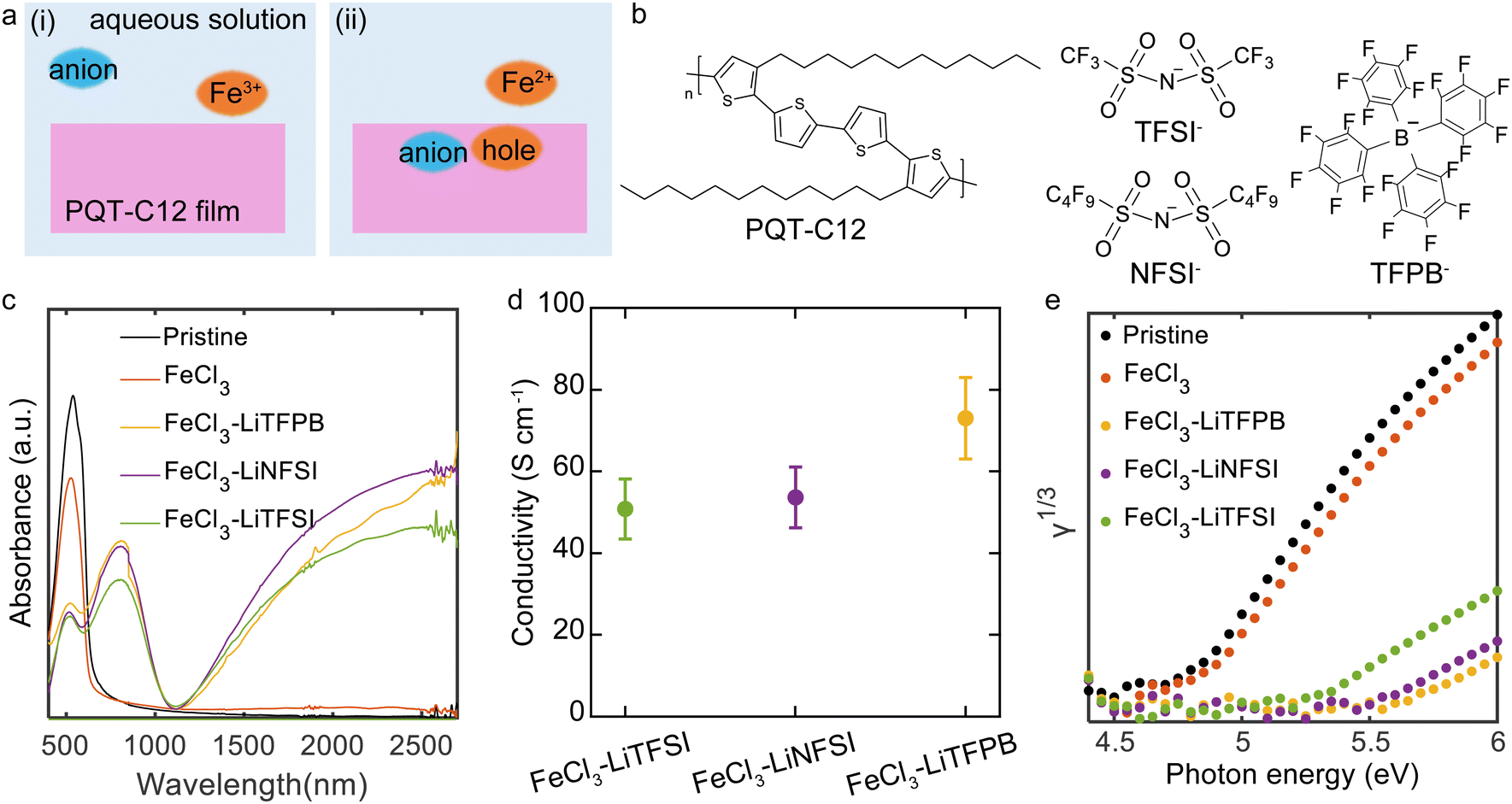 | ||
| Fig. 1 Doping of PQT thin films. (a) A model of possible chemical doping mechanism with the illustration of the (i) initial and (ii) final states of the doping system. (b) The molecular structures of employed materials. (c) UV-vis spectra of the treated and untreated PQT thin films. The gap at 800 nm is due to the change of the detector. (d) Conductivity of PQT thin films after the chemical doping process. FeCl3 and the denoted salts were dissolved in doping solutions. The two-terminal geometry with a channel length of 400 μm and a width of 2 mm was employed. Three samples were measured for each condition, where the error bar shows one standard deviation. (e) PYS spectra of the treated and untreated PQT thin films. | ||
The doping effect of the PQT thin films was characterised by UV-vis and conductivity measurements. The pristine PQT film showed a peak originating from the HOMO–LUMO transition at 527 nm34,35 (Fig. 1c). When the thin film was immersed in the FeCl3 solution without additional salts, no clear changes in the spectrum could be observed. In contrast, addition of Li-TFSI, Li-NFSI, or Li-TFPB resulted in a decreased intensity of the peak at 527 nm and new features at 770 nm and above 1100 nm. These changes are consistent with p-type doping of the polythiophene derivatives.36 The electrical conductivity of the PQT thin films was measured by fabricating doped films on glass substrates with prepatterned Cr/Au electrodes. While the conductivity of pristine and FeCl3-treated thin films was 2 × 10⁻⁷ and 7 × 10⁻⁷ S cm−1, those for anion-exchanged doped thin films were over 50 S cm−1 (Fig. 1d), which supports the successful p-type doping of PQT thin films. Representative current–voltage plots are shown in Fig. S1 (ESI†).
In an efficient doping process, the Fermi energy and IP of the semiconductor would show a large shift, which was confirmed by PYS measurements (Fig. 1e). The IPs of the thin films were determined based on the energy threshold of the third root of photoelectron yield (γ).37 Fitting of the PYS spectra is shown in Fig. S2 (ESI†). The IP of the pristine PQT thin film sample was estimated to be 4.78 eV. The PQT thin film immersed in the FeCl3 solution exhibited a slightly increased IP of 4.87 eV. In contrast, the IPs of PQT thin films doped with a combination of FeCl3 and additional salts were 5.25 eV for Li-TFSI, 5.47 eV for Li-NFSI, and 5.56 eV for Li-TFPB. These large shifts in IPs are consistent with the efficient p-type doping of PQT, where electrons are removed from the HOMO density of states. Importantly, these IPs of highly conducting polymers are equal to the work functions, where the Fermi energy is inside the HOMO density of states. The difference in work functions depending on the employed salts may not be explained by the difference in the doping level, considering the almost identical results in the UV-vis and conductivity measurements. This point is discussed after confirming the composition of dopants inside the thin films.
X-ray photoelectron spectroscopy (XPS) measurements were performed to determine the composition of the doped PQT thin films (Fig. 2). The PQT films were prepared in the same manner as in the above experiments on glass substrates with pre-coated Cr/Au. All samples showed peaks in the C 1s and S 2p regions, which is consistent with the molecular structure of PQT. When FeCl3 was employed in the doping solution, almost no changes were observed in the C 1s and S 2p peaks. Fe 2p and Cl 2p peaks were not observed, which is consistent with the low doping level for this condition. When combinations of FeCl3 and additional salts were employed, the Fe 2p and Cl 2p peaks were not observed. Instead, when Li-TFSI and Li-NFSI were employed, the introduction of TFSI− and NFSI− was suggested based on the observations of N 1s, O 1s, and F 1s peaks. In addition, in the S 2p region (Fig. 2b), the use of Li-TFSI and Li-NFSI resulted in additional peaks at 167.5 and 168 eV. These positions are consistent with the reported values for sulfur atoms in the sulfonylimide structure.38,39 When the combination of FeCl3 and Li-TFPB was employed, peaks were observed in the B 1s and F 1s regions, in addition to the C 1s and S 2p regions. In the B 1s region (Fig. 2c), there are peaks that may originate from the impurities present in the pristine sample, whereas only the sample using Li-TFPB showed an additional peak at 188.3 eV. The above results verify that our chemical doping process introduces TFSI−, NFSI−, or TFPB− when salts of these anions and FeCl3 are dissolved in the doping solutions.
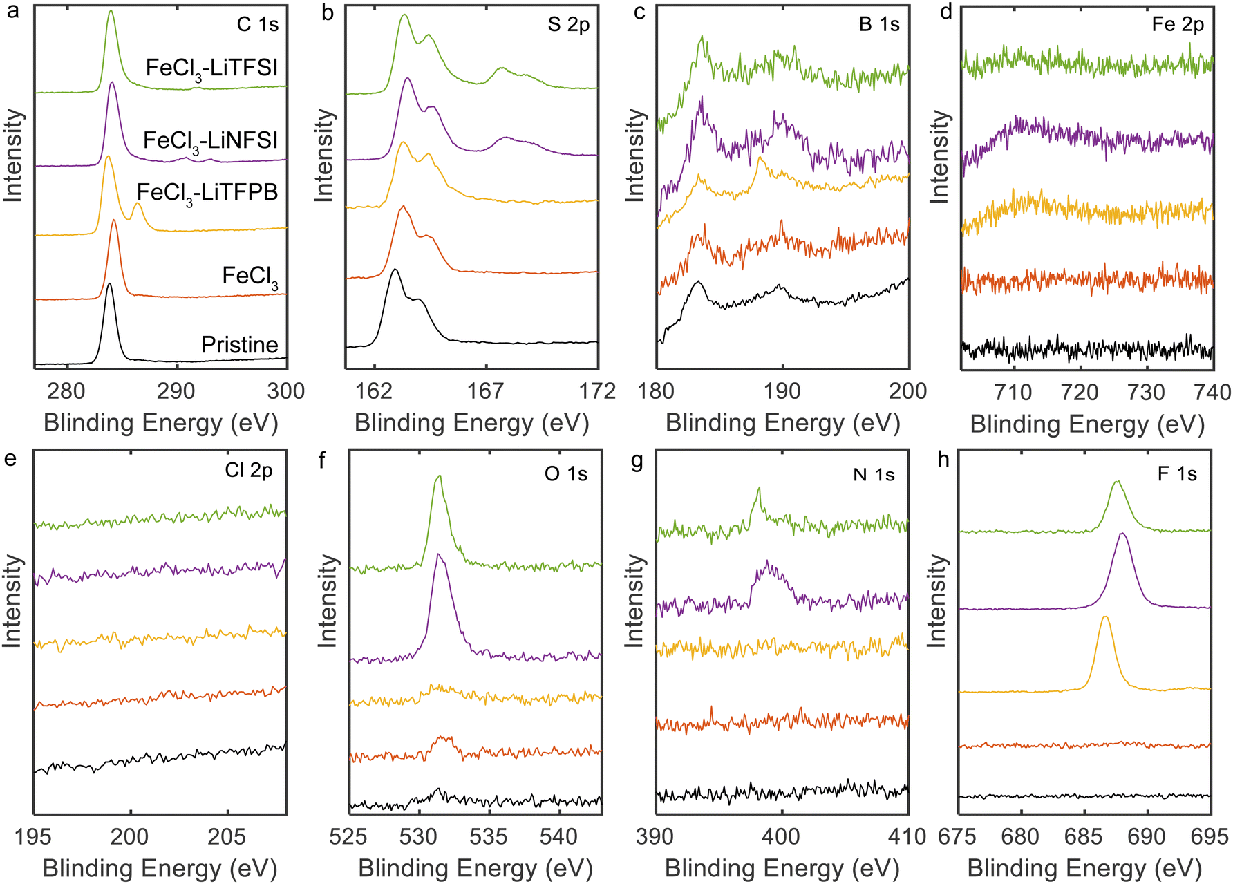 | ||
| Fig. 2 XPS spectra of doped PQT thin films: (a) C 1s, (b) S 2p, (c) B 1s, (d) Fe 2p, (e) Cl 2p, (f) O 1s, (g) N 1s, and (h) F 1s regions. | ||
Atomic compositions were calculated based on the XPS spectra and are summarized in Table 1. Based on the carbon and fluorine atomic compositions, the ratios of dopant/monomer around the surface were calculated to be 0.70, 0.54, and 0.52 for TFSI−-, NFSI−-, and TFPB−-doped films, respectively, which agrees with the high doping levels achieved in our process.
| Sample | C | S | B | O | N | F |
|---|---|---|---|---|---|---|
| Pristine | 92.4 | 7.6 | — | — | — | — |
| FeCl3 | 92.6 | 7.4 | — | — | — | — |
| FeCl3 + Li-TFSI | 78.2 | 8.7 | — | 4.4 | 0.9 | 7.9 |
| FeCl3 + Li-NFSI | 71.4 | 7.1 | — | 4.4 | 1.5 | 15.6 |
| FeCl3 + Li-TFPB | 78.9 | 5.0 | 0.4 | — | — | 15.7 |
Considering that bulky anions were introduced into the PQT thin films, the anion-dependent work functions observed in PYS measurements may be attributed to the effects of vacuum level shifts owing to dipoles between holes and counter-anions.18,40,41 In this case, the size of the dipole depends on the distance between the positive and negative charges, which should be affected by the size of the counter-anion. Thus, the large sizes of NFSI− and TFPB− may have contributed to the large work functions observed when these anions were employed compared to the case with TFSI−.
The ambient and thermal stability of the doped PQT thin films were evaluated using UV-vis spectroscopy and conductivity measurements. In UV-vis measurements, one-hour heating of doped films under air at 125 °C resulted in decreased doping levels for TFSI−- and NFSI−-doped films, which is evidenced by the increased intensity of the peak around 540 nm (Fig. 3a and b). In contrast, this heating process did not alter the spectrum of the TFPB−-doped film, indicating the high thermal stability of the sample (Fig. 3c). When the conductivity was measured under air at room temperature, the TFPB−-doped film exhibited a high retention ratio of approximately 90.1% after 20 days (Fig. 3d), which was superior to those of TFSI−- and NFSI−-doped films. The stability of the conductivity was also tested at 100 °C and 125 °C under air (Fig. 3e and f), wherein the PQT films doped with TFPB− demonstrated the highest stability among the tested samples.
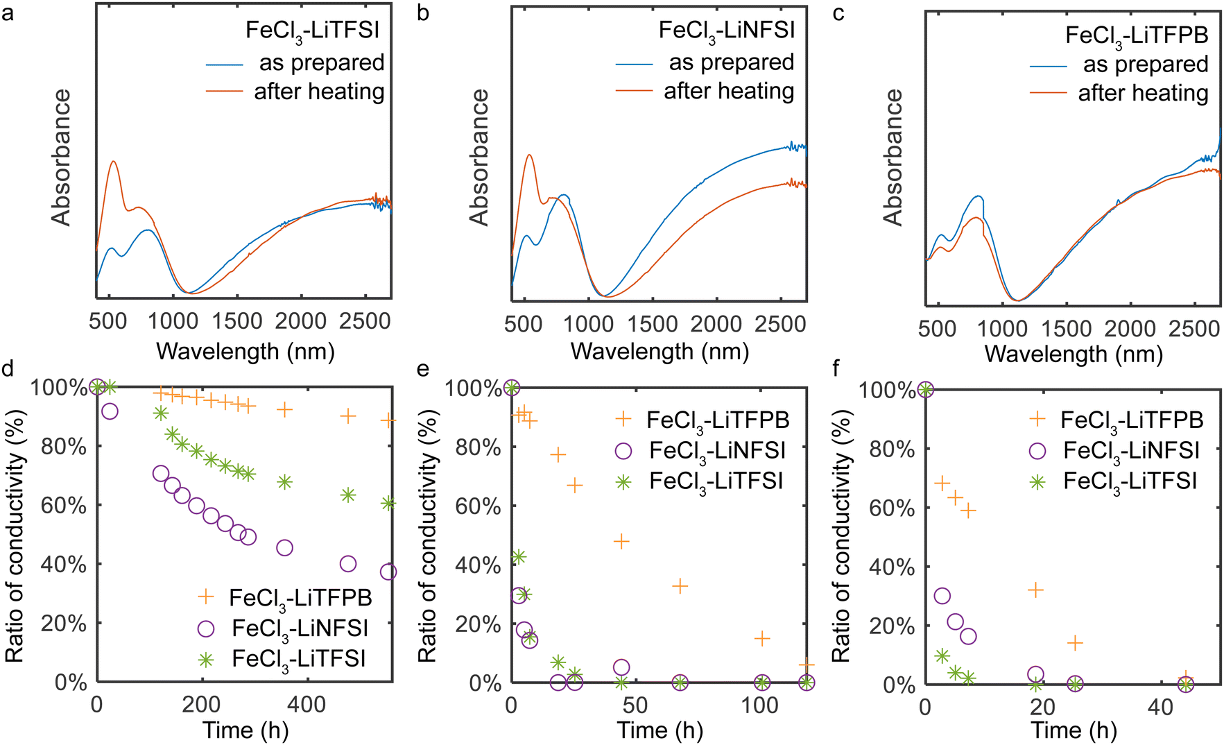 | ||
| Fig. 3 Ambient and thermal stability of the doped PQT thin films. UV-vis spectra of (a) TFPB−-, (b) NFSI−-, and (c) TFSI−-doped thin films before and after heating at 125 °C under air. The gap at 800 nm is due to the change of the detector. (d) Ambient stability of the conductivity of PQT thin films. (e) Thermal stability of the conductivity of doped PQT thin films at 100 °C and (f) 125 °C under air. After storing the thin films at elevated temperatures, conductivity measurements were performed at room temperature. The two-terminal geometry with a channel length of 400 μm and a width of 2 mm was employed. | ||
There are various mechanisms that lead to a decrease in the doping levels of p-type doped polymers under ambient conditions and high temperatures. For high work function materials, redox reactions with water are anticipated, where the use of minimally hygroscopic materials is important to improve stability.18,42,43 In addition to this, degradation through other mechanisms needs to be considered. When polymers are doped with FeCl3 or anion-exchange doped using FeCl3, side reactions with FeCl3 or chemicals originating from it including FeCl4− and Cl− possibly occur.15 Other possibilities include deprotonation of doped polymers that leaves the polymer in the neutral state.31 To understand the major cause of the dedoping in our system, stability tests were also conducted in a nitrogen purged glove box. Here, we observed severe dedoping for TFSI−- and NFSI−-doped films, while the TFPB−-doped film did not show dedoping features (Fig. S4 and S5, ESI†). This manifests that dedoping of TFSI−- and NFSI−-doped films mainly occurs not by redox reactions with water but by self-degradation of the employed materials at high temperatures. In our case, the degradation by side reactions with FeCl3 or chemicals originating from it may not be the main cause of the observed dedoping considering that Fe and Cl atoms were not observed in XPS measurements of the thin films after the doping and surface washing procedures. Other degradation reactions such as deprotonation of the positively charged polymers31 might be the main cause of the dedoping, where the proton affinity of dopant ions and the relative position between the semiconductor and dopant ions would be important.
To understand the structural changes upon heating for the doped PQT thin films, XRD measurements were performed (Fig. 4). When a proper choice of dopant molecule is employed to a polythiophene derivative, a highly crystalline doped state has been demonstrated.44–46 In the out-of-plane direction, the pristine film showed the (100) peak at 0.29 Å−1 corresponding to a d-spacing of 21.4 Å, consistent with the literature.47 While the thin film treated with the FeCl3 solution showed an almost identical peak position of the (100) diffraction, TFSI−-, NFSI−- and TFPB−-doped PQT thin films showed an increase in d-spacing. The estimated values of d100 are summarized in Table 2. The d100 of TFPB−-doped PQT was greater than those of the other samples, indicating that the larger molecular size of TFPB− resulted in a larger lamellar spacing compared to the case with NFSI− and TFSI− consistent with the literature.48 After one-hour heating at 125 °C, TFSI−- and NFSI−-doped PQT thin films showed a decrease in d100, where the shrinkage of lamellar spacing occurred probably through removal of dopant anions from the thin films. On the other hand, the TFPB−-doped film showed an almost unchanged lamellar spacing after the thermal treatment, which manifests the structural stability of the combination of PQT and TFPB−.
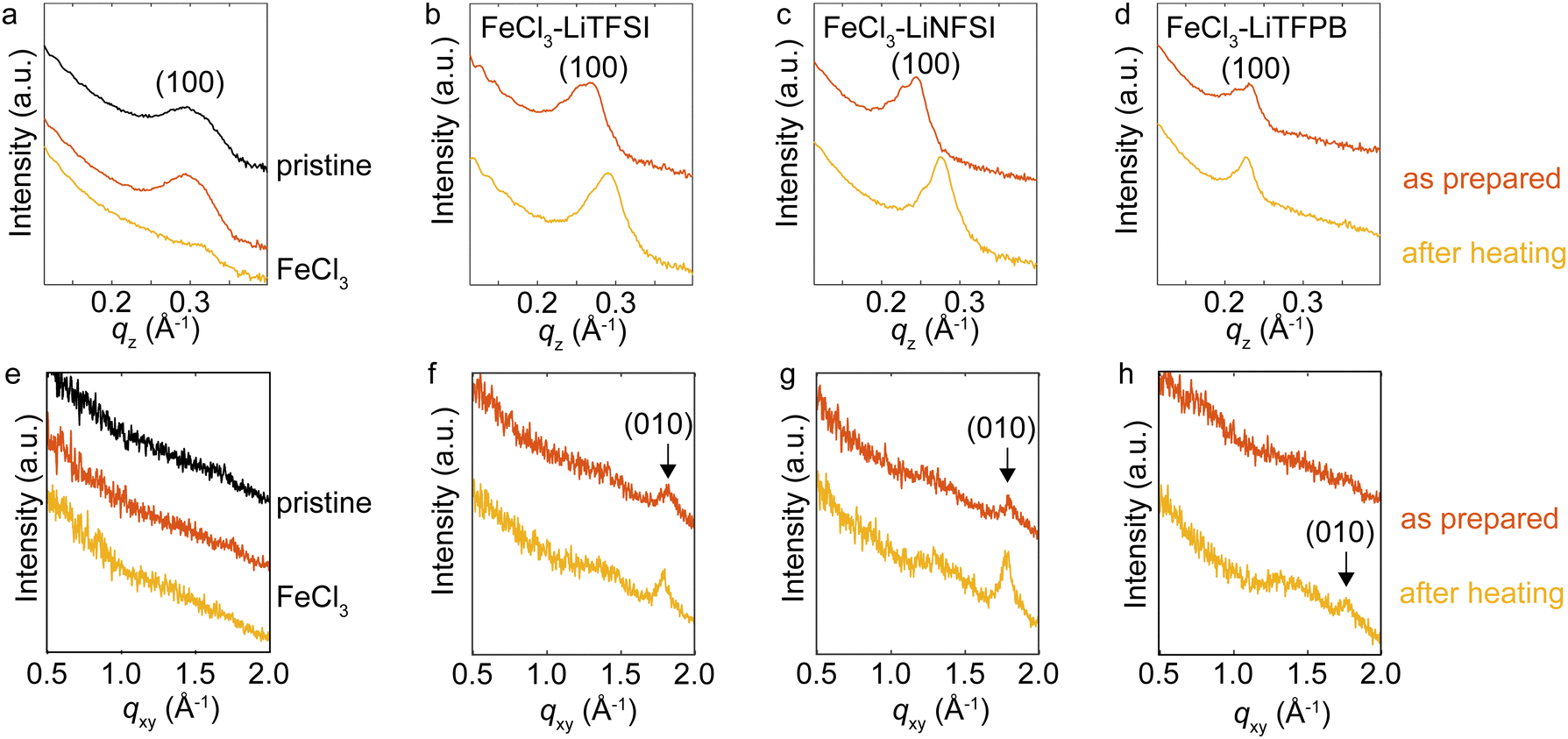 | ||
| Fig. 4 XRD measurements of the doped PQT thin films. Intensities for the (a)–(d) out-of-plane and (e)–(h) in-plane directions. Orange plots were obtained from thin films after treatment with FeCl3 or combinations of FeCl3 and additional salts. Yellow plots were obtained after heating the treated samples at 125 °C under air. | ||
| Sample | d 100 (Å) | FWHM (Å−1) |
|---|---|---|
| Pristine | 21.35 ± 0.01 | 0.0647 ± 0.0007 |
| FeCl3 as prepared | 21.37 ± 0.01 | 0.0521 ± 0.0006 |
| FeCl3 after heating | 20.30 ± 0.07 | 0.0406 ± 0.0028 |
| TFSI− as prepared | 23.92 ± 0.03 | 0.0381 ± 0.0010 |
| TFSI− after heating | 21.73 ± 0.01 | 0.0276 ± 0.0005 |
| NFSI− as prepared | 26.17 ± 0.03 | 0.0308 ± 0.0010 |
| NFSI− after heating | 22.76 ± 0.01 | 0.0204 ± 0.0003 |
| TFPB− as prepared | 27.87 ± 0.06 | 0.0355 ± 0.0015 |
| TFPB− after heating | 27.77 ± 0.02 | 0.0209 ± 0.0004 |
Evaluation in the in-plane direction was conducted based on wide angle X-ray scattering images (Fig. S3, ESI†), which were converted to one-dimensional plots (Fig. 4e–h). The (010) peaks that correspond to π-stacking periodicity49 were observed for TFSI−- and NFSI−-doped films with a d-spacing of 3.5 Å. For the TFPB−-doped film, this peak was clearly observed after the thermal treatment, which indicates that this thermal treatment was necessary to obtain a stable crystalline structure for this sample. The d-spacing of TFPB− after the thermal treatment was 3.5 Å, where this small value is advantageous for two-dimensional carrier transport.44
The above XRD measurements suggest that intercalation of employed dopant anions into the PQT lamella occurs in our method. Considering that the combination of PBTTT and TFPB− was reported to result in a disordered structure,50 the longer separation between the alkyl side chains of PQT compared to P3HT and PBTTT may have contributed to the formation of a large void space to accommodate TFPB−. When intercalation of dopant anions occurs, the anions and π-stacked semiconductor backbones are in close contact. The degradation of polymers through the deprotonation process31 might be accelerated by the oxygen atoms in TFSI− and NFSI−. After this process, the protonated dopant anions may be removed from the PQT lamella, which is supported by the shrinkage of lamellar spacing after heating as observed in our XRD measurements. Suppression of such self-degradation reactions for the case with the TFPB−doped film may owe to the inert molecular structure of TFPB− without oxygen atoms. Also, the minimally hygroscopic nature of TFPB− would be advantageous to suppress possible dedoping by redox reactions with water. Further chemical analysis using mass spectroscopy,15 nuclear spin resonance,51,52 vibrational spectroscopy31 or computational simulation53 of the degraded polymers would clarify the dedoping mechanisms which can vary depending on the employed materials and environments.
Conclusion
In this study, the chemical doping of PQT thin films was performed under ambient conditions using aqueous solutions containing FeCl3 and additional salts. The successful doping of the PQT thin films was corroborated by UV-vis, conductivity, PYS, and XPS measurements, where holes and TFSI−, NFSI−, or TFPB− were introduced into the thin films. When the bulkiest TFPB− served as the dopant anion, enhanced stability of the doped state was demonstrated in the aging test at room temperature and high temperatures of 100 °C and 125 °C. The stability performance was markedly superior to those of other dopant candidates and previously reported literature. Through XRD measurements, the thin-film structures of the doped PQT were evaluated, and PQT was found to accommodate the bulky anions while maintaining the lamellar and π-stacking structures. For the TFPB−-doped thin film, the UV-Vis, conductivity, and d-spacing results remained almost unaltered upon heating at 125 °C for 1 h. Compared to other employed dopant ions, suppression of the self-degradation reactions at high temperatures seemed to be the key in addition to the suppression of redox reactions with water in air. The high work function and stability observed in the TFPB−-doped PQT thin film highlights the possibility of achieving a high work function and stable doped organic semiconductors by designing the host–guest combinations.Experimental
Fabrication
For the fabrication of PQT thin films, EAGLE XG glass substrates were employed for UV-vis, conductivity, PYS, and XPS measurements. Cr/Au was pre-deposited for conductivity, PYS, and XPS measurements. Si wafers with naturally oxidized layers were employed as the substrate for XRD measurements. The thin film deposition process involved spin coating from a 1 wt% o-dichlorobenzene solution at a spinning speed of 2000 rpm for 1 minute. Subsequently, the deposited films underwent annealing in a vacuum oven and maintained at 100 °C for 1 hour, followed by a slow cooling process. The thickness of the pristine PQT film was determined to be ca. 25 nm based on the AFM images in Fig. S6 (ESI†). The thickness of the doped films was assumed to be increased by the same factor as the increase in lamellar spacing. The PQT films were doped by simply immersing them in aqueous dopant solutions at room temperature. The doping solutions were prepared by dissolving dopant salts (100 mM for LiTFSI and 1 mM for LiNFSI and LiTFPB) and FeCl3 (10 mM) in a binary solvent mixture consisting of an aqueous sulfuric acid solution (80 wt%) at pH 2 and acetonitrile (20 wt%). The immersion process was carried out for 60 minutes, after which the residual doping solution was removed by blowing Ar gas. The surface of the samples was washed with pure water after this process.Evaluation
Electrical conductivities were measured in air using a Keithley 2612B source meter with a two-terminal geometry with a channel length of 400 μm and a width of 2 mm. UV-vis absorption spectra were obtained using a V670 (JASCO) spectrometer. XRD data were acquired using a RIGAKU SmartLab with a MicroMax-007HF X-ray generator using Cu Kα radiation (λ = 0.15418 nm). XPS was performed using a KRATOS ULTRA 2 instrument with monochromatic Al Kα X-rays.Author contributions
Z. X. and Y. Y. designed the experiments. Z. X. and M. I. performed the experiments. J. T. and K. A. supervised the work. Z. X. and Y. Y. analyzed the data and wrote the manuscript.Data availability
The data supporting this article have been included as part of the main text and the ESI.†Conflicts of interest
There are no conflicts to declare.Acknowledgements
This work was supported in part by the JSPS KAKENHI grant (no. JP20H00392 and JP22H02160) and the JST, CREST Grant (No. JPMJCR21O3), Japan.References
- Y. Xu, H. Sun, A. Liu, H.-H. Zhu, W. Li, Y.-F. Lin and Y.-Y. Noh, Adv. Mater., 2018, 30, 1801830 CrossRef PubMed
.
- K. Loganathan, A. D. Scaccabarozzi, H. Faber, F. Ferrari, Z. Bizak, E. Yengel, D. R. Naphade, M. Gedda, Q. He and O. Solomeshch,
et al.
, Adv. Mater., 2022, 34, 2108524 CrossRef CAS PubMed
- M. Gross, D. C. Müller, H.-G. Nothofer, U. Scherf, D. Neher, C. Bräuchle and K. Meerholz, Nature, 2000, 405, 661–665 CrossRef CAS PubMed
- X. Lin, B. Wegner, K. M. Lee, M. A. Fusella, F. Zhang, K. Moudgil, B. P. Rand, S. Barlow, S. R. Marder and N. Koch,
et al.
, Nat. Mater., 2017, 16, 1209–1215 CrossRef CAS PubMed
- V. A. Kolesov, C. Fuentes-Hernandez, W.-F. Chou, N. Aizawa, F. A. Larrain, M. Wang, A. Perrotta, S. Choi, S. Graham and G. C. Bazan,
et al.
, Nat. Mater., 2017, 16, 474–480 CrossRef CAS PubMed
- C. Zhao, C. G. Tang, Z.-L. Seah, Q.-M. Koh, L.-L. Chua, R.-Q. Png and P. K. Ho, Nat. Commun., 2021, 12, 2250 CrossRef CAS PubMed
- T. Wang, Y. Zhang, W. Kong, L. Qiao, B. Peng, Z. Shen, Q. Han, H. Chen, Z. Yuan and R. Zheng,
et al.
, Science, 2022, 377, 1227–1232 CrossRef CAS PubMed
- H. Bronstein, C. B. Nielsen, B. C. Schroeder and I. McCulloch, Nat. Rev. Chem., 2020, 4, 66–77 CrossRef CAS PubMed
- S. Fratini, M. Nikolka, A. Salleo, G. Schweicher and H. Sirringhaus, Nat. Mater., 2020, 19, 491–502 CrossRef CAS PubMed
- W. Spear and P. Le Comber, Solid State Commun., 1975, 17, 1193–1196 CrossRef
- S. N. Patel, A. M. Glaudell, K. A. Peterson, E. M. Thomas, K. A. O’Hara, E. Lim and M. L. Chabinyc, Sci. Adv., 2017, 3, e1700434 CrossRef PubMed
- Y. Lu, Z.-D. Yu, Y. Liu, Y.-F. Ding, C.-Y. Yang, Z.-F. Yao, Z.-Y. Wang, H.-Y. You, X.-F. Cheng and B. Tang,
et al.
, J. Am. Chem. Soc., 2020, 142, 15340–15348 CrossRef CAS PubMed
- E. M. Thomas, K. A. Peterson, A. H. Balzer, D. Rawlings, N. Stingelin, R. A. Segalman and M. L. Chabinyc, Adv. Electron. Mater., 2020, 6, 2000595 CrossRef CAS
- L. Ding, Z.-D. Yu, X.-Y. Wang, Z.-F. Yao, Y. Lu, C.-Y. Yang, J.-Y. Wang and J. Pei, Chem. Rev., 2023, 123, 7421–7497 CrossRef CAS PubMed
- M. Jha, J. Mogollon Santiana, A. A. Jacob, K. Light, M. L. Hong, M. R. Lau, L. R. Filardi, H. Miao, S. M. Gurses and C. X. Kronawitter,
et al.
, J. Phys. Chem. C, 2024, 128, 1258–1266 CrossRef CAS
- I. E. Jacobs and A. J. Moulé, Adv. Mater., 2017, 29, 1703063 CrossRef PubMed
- D. Yuan, W. Liu and X. Zhu, Chem. Soc. Rev., 2023, 52, 3842–3872 RSC
- C. G. Tang, M. C. Y. Ang, K.-K. Choo, V. Keerthi, J.-K. Tan, M. N. Syafiqah, T. Kugler, J. H. Burroughes, R.-Q. Png, L.-L. Chua and P. K. H. Ho, Nature, 2016, 539, 536–540 CrossRef CAS PubMed
- A. Kumar, K. Intonti, L. Viscardi, O. Durante, A. Pelella, O. Kharsah, S. Sleziona, F. Giubileo, N. Martucciello and P. Ciambelli,
et al.
, Mater. Horiz., 2024, 11, 2397–2405 RSC
- P. A. Bobbert, A. Sharma, S. G. Mathijssen, M. Kemerink and D. M. de Leeuw, Adv. Mater., 2012, 24, 1146–1158 CrossRef CAS PubMed
- T. Kurosawa, Y. Yamashita, Y. Kobayashi, C. P. Yu, S. Kumagai, T. Mikie, I. Osaka, S. Watanabe, J. Takeya and T. Okamoto, Macromolecules, 2024, 57, 328–338 CrossRef
- R. Kroon, D. Kiefer, D. Stegerer, L. Yu, M. Sommer and C. Müller, Adv. Mater., 2017, 29, 1700930 CrossRef PubMed
- G. Zuo, M. Linares, T. Upreti and M. Kemerink, Nat. Mater., 2019, 18, 588–593 CrossRef CAS PubMed
- S. Griggs, A. Marks, H. Bristow and I. McCulloch, J. Mater. Chem. C, 2021, 9, 8099–8128 RSC
- Y. Yamashita, J. Tsurumi, M. Ohno, R. Fujimoto, S. Kumagai, T. Kurosawa, T. Okamoto, J. Takeya and S. Watanabe, Nature, 2019, 572, 634–638 CrossRef CAS PubMed
- D. Yuan, E. Plunkett, P. H. Nguyen, D. Rawlings, M. L. Le, R. Kroon, C. Müller, R. A. Segalman and M. L. Chabinyc, Adv. Funct. Mater., 2023, 33, 2300934 CrossRef CAS
- T. L. Murrey, M. A. Riley, G. Gonel, D. D. Antonio, L. Filardi, N. Shevchenko, M. Mascal and A. J. Moulé, J. Phys. Chem. Lett., 2021, 12, 1284–1289 CrossRef CAS PubMed
- I. E. Jacobs, Y. Lin, Y. Huang, X. Ren, D. Simatos, C. Chen, D. Tjhe, M. Statz, L. Lai and P. A. Finn,
et al.
, Adv. Mater., 2022, 34, 2102988 CrossRef CAS PubMed
- E. M. Thomas, K. A. Peterson, A. H. Balzer, D. Rawlings, N. Stingelin, R. A. Segalman and M. L. Chabinyc, Adv. Electron. Mater., 2020, 6, 2000595 CrossRef CAS
- Y. Yamashita, J. Tsurumi, T. Kurosawa, K. Ueji, Y. Tsuneda, S. Kohno, H. Kempe, S. Kumagai, T. Okamoto, J. Takeya and S. Watanabe, Commun. Mater., 2021, 2, 45 CrossRef CAS
- H. Koizumi, H. Dougauchi and T. Ichikawa, J. Phys. Chem. B, 2005, 109, 15288–15290 CrossRef CAS PubMed
- M. Ishii, Y. Yamashita, S. Watanabe, K. Ariga and J. Takeya, Nature, 2023, 622, 285–291 CrossRef CAS PubMed
- J. D. Hem and W. H. Cropper, Survey of ferrous-ferric chemical equilibria and redox potentials, Usgpo, technical report, 1959.
- A. P. Yuen, A.-M. Hor, S. M. Jovanovic, J. S. Preston, R. A. Klenkler, N. M. Bamsey and R. O. Loutfy, Sol. Energy Mater. Sol. Cells, 2010, 94, 2455–2458 CrossRef CAS
- R. K. Pandey, S. K. Yadav, C. Upadhyay, R. Prakash and H. Mishra, Nanoscale, 2015, 7, 6083–6092 RSC
- Y. Zhong, V. Untilova, D. Muller, S. Guchait, C. Kiefer, L. Herrmann, N. Zimmermann, M. Brosset, T. Heiser and M. Brinkmann, Adv. Funct. Mater., 2022, 32, 2202075 CrossRef CAS
- S. Tadano, Y. Nakayama, H. Kinjo, H. Ishii and P. Krüger, Phys. Rev. Appl., 2019, 11, 054081 CrossRef CAS
- S. Leroy, H. Martinez, R. Dedryvère, D. Lemordant and D. Gonbeau, Appl. Surf. Sci., 2007, 253, 4895–4905 CrossRef CAS
- C. Liu, X. Ma, F. Xu, L. Zheng, H. Zhang, W. Feng, X. Huang, M. Armand, J. Nie, H. Chen and Z. Zhou, Electrochim. Acta, 2014, 149, 370–385 CrossRef CAS
- P.-J. Chia, S. Sivaramakrishnan, M. Zhou, R.-Q. Png, L.-L. Chua, R. H. Friend and P. K. Ho, Phys. Rev. Lett., 2009, 102, 096602 CrossRef PubMed
- B. Wegner, D. Lungwitz, A. E. Mansour, C. E. Tait, N. Tanaka, T. Zhai, S. Duhm, M. Förster, J. Behrends and Y. Shoji,
et al.
, Adv. Sci., 2020, 7, 2001322 CrossRef CAS PubMed
- C. G. Tang, M. N. Syafiqah, Q.-M. Koh, M. C.-Y. Ang, K.-K. Choo, M.-M. Sun, M. Callsen, Y.-P. Feng, L.-L. Chua, R.-Q. Png and P. K. H. Ho, Nat. Commun., 2023, 14, 3978 CrossRef CAS PubMed
- T. Kurosawa, T. Okamoto, Y. Yamashita, S. Kumagai, S. Watanabe and J. Takeya, Adv. Sci., 2021, 8, 2101998 CrossRef CAS PubMed
- K. Kang, S. Watanabe, K. Broch, A. Sepe, A. Brown, I. Nasrallah, M. Nikolka, Z. Fei, M. Heeney and D. Matsumoto,
et al.
, Nat. Mater., 2016, 15, 896–902 CrossRef CAS PubMed
- A. Hamidi-Sakr, L. Biniek, J.-L. Bantignies, D. Maurin, L. Herrmann, N. Leclerc, P. Lévêque, V. Vijayakumar, N. Zimmermann and M. Brinkmann, Adv. Funct. Mater., 2017, 27, 1700173 CrossRef
- V. Untilova, T. Biskup, L. Biniek, V. Vijayakumar and M. Brinkmann, Macromolecules, 2020, 53, 2441–2453 CrossRef CAS
- J. Song, Q. Hu, M. Zhang, Q. Zhang, L. Zhu, J. Ali, C. Wang, W. Feng, T. Russell and F. Liu, J. Mater. Chem. C, 2020, 8, 11695–11703 RSC
- C. Chen, I. E. Jacobs, K. Kang, Y. Lin, C. Jellett, B. Kang, S. B. Lee, Y. Huang, M. BaloochQarai and R. Ghosh,
et al.
, Adv. Energy Mater., 2023, 13, 2202797 CrossRef CAS
- L. H. Jimison, A. Salleo, M. L. Chabinyc, D. P. Bernstein and M. F. Toney, Phys. Rev. B: Condens. Matter Mater. Phys., 2008, 78, 125319 CrossRef
- S. Kohno, Y. Yamashita, N. Kasuya, T. Mikie, I. Osaka, K. Takimiya, J. Takeya and S. Watanabe, Commun. Mater., 2020, 1, 79 CrossRef
- B. Yurash, D. X. Cao, V. V. Brus, D. Leifert, M. Wang, A. Dixon, M. Seifrid, A. E. Mansour, D. Lungwitz and T. Liu,
et al.
, Nat. Mater., 2019, 18, 1327–1334 CrossRef CAS PubMed
- A. Hochgesang, A. Erhardt, J. Mohanraj, M. Kuhn, E. M. Herzig, S. Olthof and M. Thelakkat, Adv. Funct. Mater., 2023, 33, 2300614 CrossRef CAS
- P. S. Marqués, G. Londi, B. Yurash, T.-Q. Nguyen, S. Barlow, S. R. Marder and D. Beljonne, Chem. Sci., 2021, 12, 7012–7022 RSC
Footnote |
| † Electronic supplementary information (ESI) available. See DOI: https://doi.org/10.1039/d4tc01406e |
| This journal is © The Royal Society of Chemistry 2024 |